DE102015114697B4 - Holding frame for connector modules - Google Patents
Holding frame for connector modules Download PDFInfo
- Publication number
- DE102015114697B4 DE102015114697B4 DE102015114697.5A DE102015114697A DE102015114697B4 DE 102015114697 B4 DE102015114697 B4 DE 102015114697B4 DE 102015114697 A DE102015114697 A DE 102015114697A DE 102015114697 B4 DE102015114697 B4 DE 102015114697B4
- Authority
- DE
- Germany
- Prior art keywords
- holding frame
- locking element
- halves
- another
- connector modules
- Prior art date
- Legal status (The legal status is an assumption and is not a legal conclusion. Google has not performed a legal analysis and makes no representation as to the accuracy of the status listed.)
- Active
Links
Images


Classifications
-
- H—ELECTRICITY
- H01—ELECTRIC ELEMENTS
- H01R—ELECTRICALLY-CONDUCTIVE CONNECTIONS; STRUCTURAL ASSOCIATIONS OF A PLURALITY OF MUTUALLY-INSULATED ELECTRICAL CONNECTING ELEMENTS; COUPLING DEVICES; CURRENT COLLECTORS
- H01R13/00—Details of coupling devices of the kinds covered by groups H01R12/70 or H01R24/00 - H01R33/00
- H01R13/46—Bases; Cases
- H01R13/516—Means for holding or embracing insulating body, e.g. casing, hoods
- H01R13/518—Means for holding or embracing insulating body, e.g. casing, hoods for holding or embracing several coupling parts, e.g. frames
-
- H—ELECTRICITY
- H01—ELECTRIC ELEMENTS
- H01R—ELECTRICALLY-CONDUCTIVE CONNECTIONS; STRUCTURAL ASSOCIATIONS OF A PLURALITY OF MUTUALLY-INSULATED ELECTRICAL CONNECTING ELEMENTS; COUPLING DEVICES; CURRENT COLLECTORS
- H01R13/00—Details of coupling devices of the kinds covered by groups H01R12/70 or H01R24/00 - H01R33/00
- H01R13/46—Bases; Cases
- H01R13/502—Bases; Cases composed of different pieces
- H01R13/512—Bases; Cases composed of different pieces assembled by screw or screws
-
- H—ELECTRICITY
- H01—ELECTRIC ELEMENTS
- H01R—ELECTRICALLY-CONDUCTIVE CONNECTIONS; STRUCTURAL ASSOCIATIONS OF A PLURALITY OF MUTUALLY-INSULATED ELECTRICAL CONNECTING ELEMENTS; COUPLING DEVICES; CURRENT COLLECTORS
- H01R13/00—Details of coupling devices of the kinds covered by groups H01R12/70 or H01R24/00 - H01R33/00
- H01R13/46—Bases; Cases
- H01R13/514—Bases; Cases composed as a modular blocks or assembly, i.e. composed of co-operating parts provided with contact members or holding contact members between them
Landscapes
- Connector Housings Or Holding Contact Members (AREA)
Abstract
Halterahmen (1), in welchen Steckverbindermodule (19) einsetzbar sind, wobei der Halterahmen (1) aus zwei miteinander verbindbaren Hälften (4, 5), einer ersten Hälfte (4) und einer zweiten Hälfte (5), besteht, wobei die Hälften (4, 5) in zumindest zwei Positionen zueinander ausrichtbar sind und wobei der Halterahmen (1) zumindest ein erstes Sperrelement (7) aufweist dadurch gekennzeichnet, dass
- zumindest eine Hälfte (5) des Halterahmens (1) stirnseitig einen Dorn (14) aufweist und das erste Sperrelement (7) zumindest zwei Aussparungen (12, 12') aufweist, wobei der Dorn (14) in die zumindest zwei Aussparungen (12, 12') eingreifen kann und dadurch die Hälften (4, 5) in zumindest zwei Positionen zueinander ausrichtbar und fixierbar sind oder
- zumindest eine Hälfte (5) des Halterahmens (1) stirnseitig zumindest zwei Dorne (14) aufweist und das erste Sperrelement (7) eine Aussparung (12) aufweist, wobei die zumindest zwei Dorne (14) jeweils in die Aussparung (12) eingreifen können und dadurch die Hälften (4, 5) in zumindest zwei Positionen zueinander ausrichtbar und fixierbar sind.

- At least one half (5) of the holding frame (1) has a spike (14) on the end face and the first locking element (7) has at least two recesses (12, 12 '), the spike (14) into the at least two recesses (12 , 12 ') and thereby the halves (4, 5) can be aligned and fixed relative to one another in at least two positions, or
- At least one half (5) of the holding frame (1) has at least two spikes (14) on the end face and the first locking element (7) has a recess (12), the at least two spikes (14) each engaging in the recess (12) and thus the halves (4, 5) can be aligned and fixed to one another in at least two positions.
Description
Die Erfindung geht aus von einem Halterahmen für Steckverbindermodule nach dem Oberbegriff des unabhängigen Anspruchs 1.The invention relates to a holding frame for connector modules according to the preamble of
Derartige Halterahmen dienen zur Halterung von Steckverbindermodulen, wobei der Halterahmen mit verschiedenen Steckverbindermodulen bestückt und anschließend in ein Steckverbindergehäuse eingesetzt und mit diesem verschraubt wird. Dabei muss der Halterahmen mechanisch stabil sein, um den auftretenden Steck- und Ziehkräften beim Zusammenfügen bzw. Trennen der Steckverbindung standhalten zu können.Such holding frames are used to hold connector modules, the holding frame being equipped with various connector modules and then inserted into a connector housing and screwed to it. The holding frame must be mechanically stable in order to be able to withstand the plugging and pulling forces that occur when joining or disconnecting the plug connection.
Stand der TechnikState of the art
Aus der
Die
Die
Der Halterahmen der
Bei erfolgreicher Bestückung des Halterahmens mit Steckverbindermodulen muss dieser in einen geschlossen Zustand beziehungsweise in eine geschlossene Position gebracht werden, damit die Steckverbindermodule fixiert sind. Für den geschlossenen Zustand des Halterahmens des Standes der Technik gibt es keinen fixierten geschlossenen Zustand, so dass sich der Halterahmen versehentlich öffnen kann, wodurch die Module aus ihrer Verankerung fallen können. If the holding frame is successfully fitted with connector modules, it must be brought into a closed state or into a closed position so that the connector modules are fixed. There is no fixed closed state for the closed state of the holding frame of the prior art, so that the holding frame can open accidentally, as a result of which the modules can fall out of their anchoring.
Durch eine reine gelenkige Verbindung ist ein definierter elektrischer Kontakt zwischen den Hälften des Halterahmens nicht immer gewährleistet. Eine Erdungsfunktion kann der oben geschilderte Halterahmen daher nicht zuverlässig übernehmen.A purely articulated connection does not always guarantee a defined electrical contact between the halves of the holding frame. The above-described holding frame cannot therefore reliably perform an earthing function.
AufgabenstellungTask
Die Aufgabe der Erfindung besteht darin einen Halterahmen vorzuschlagen der einfach handhabbar und vielseitig einsetzbar ist.The object of the invention is to propose a holding frame that is easy to handle and versatile.
Die Aufgabe wird durch die kennzeichnenden Merkmale des unabhängigen Anspruchs 1 gelöst.The object is achieved by the characterizing features of
Vorteilhafte Ausgestaltungen der Erfindung sind in den Unteransprüchen angegeben.Advantageous embodiments of the invention are specified in the subclaims.
Der erfindungsgemäße Halterahmen ist dafür vorgesehen Steckverbindermodule aufzunehmen. Anschließend wird der Halterahmen in ein Steckverbindergehäuse eingebaut beziehungsweise an eine Wandfläche, beispielsweise einer Maschine, angeschraubt.The holding frame according to the invention is intended to accommodate connector modules. The holding frame is then installed in a connector housing or screwed to a wall surface, for example a machine.
Der Halterahmen besteht aus zwei miteinander verbindbaren Hälften. Jede dieser Hälften weist eine Seitenfläche und eine Stirnseite aus. Die beiden Hälften definieren in etwa in ihrem Kontaktbereich eine Trennungsebene, die parallel zu den Längsseiten der Hälften verläuft.The holding frame consists of two halves that can be connected together. Each of these halves has a side surface and an end face. The two halves roughly define a separation plane in their contact area, which runs parallel to the long sides of the halves.
Der Halterahmen weist zumindest ein erstes Sperrelement auf, wodurch die Hälften in zumindest zwei Positionen zueinander ausrichtbar und fixierbar sind. Eine erste Position stellt die offene Position dar und ermöglich ein leichtes einsetzen der Steckverbindermodule in den Halterahmen. Eine zweite Position stellt die geschlossene Position dar. In der geschlossenen Position werden die Steckverbindermodule im Halterahmen reversibel gehalten. Der Halterahmen kann nun einfach in ein Steckverbindergehäuse eingebaut werden, ohne das die Steckverbindermodule noch verrutschen oder hinausfallen könnten.The holding frame has at least one first locking element, as a result of which the halves can be aligned and fixed relative to one another in at least two positions. A first position represents the open position and enables the connector modules to be inserted easily into the holding frame. A second position represents the closed position. In the closed position, the connector modules in the Retaining frame held reversibly. The holding frame can now be easily installed in a connector housing without the connector modules still slipping or falling out.
Der Halterahmen kann wahlweise in einer offenen Position oder in einer geschlossenen Position fixiert werden.The holding frame can either be fixed in an open position or in a closed position.
Vorzugsweise kann der Halterahmen zwei erste Sperrelemente aufweisen, die an den jeweiligen Stirnseiten des Halterahmens angeordnet sind.The holding frame can preferably have two first locking elements which are arranged on the respective end faces of the holding frame.
Außerdem sind die Hälften über das erste Sperrelement elektrisch leitend miteinander verbunden, sofern das erste Sperrelement und die Hälften aus einem elektrisch leitenden Material bestehen. Die elektrisch leitende Verbindung ist besonders stabil, wenn sich der Halterahmen im oberen beschriebenen geschlossenen Zustand befindet.In addition, the halves are electrically conductively connected to one another via the first locking element, provided that the first locking element and the halves are made of an electrically conductive material. The electrically conductive connection is particularly stable when the holding frame is in the closed state described above.
Vorteilhafterweise ist das erste Sperrelement im Wesentlichen U-förmig ausgestaltet. Das Sperrelement überdeckt die Stirnseiten der beiden Hälften des Halterahmens. Dadurch baut der erfindungsgemäße Halterahmen nicht größer auf als die bekannten Halterahmen.Advantageously, the first locking element is essentially U-shaped. The locking element covers the end faces of the two halves of the holding frame. As a result, the holding frame according to the invention is no larger than the known holding frame.
Vorteilhafterweise handelt es sich beim Sperrelement um ein Sperrblech, welches aus metallischem Material gefertigt ist. Durch das metallische Material kann eine leitende Verbindung zwischen den Hälften des Halterahmens hergestellt werden.The locking element is advantageously a locking plate which is made of metallic material. The metallic material can be used to establish a conductive connection between the halves of the holding frame.
Besonders vorteilhaft ist es, wenn das erste Sperrelement einseitig an einer Hälfte des Halterahmens fixiert ist und anderseitig kraftschlüssig mit der anderen Hälfte des Halterahmens verbunden ist. Anstatt einer reinen kraftschlüssigen Verbindung kann auch eine Form-Kraftschluss-Verbindung vorgesehen sein. Dies wird im Folgenden näher erläutert. It is particularly advantageous if the first locking element is fixed on one side to one half of the holding frame and is non-positively connected on the other side to the other half of the holding frame. Instead of a purely positive connection, a positive-positive connection can also be provided. This is explained in more detail below.
Erfindungsgemäß ist an zumindest einer Hälfte des Halterahmens stirnseitig ein Dorn vorgesehen. Das erste Sperrelement weist zumindest zwei zugehörige Aussparungen auf, wobei der Dorn in die zumindest zwei Aussparungen eingreifen kann und dadurch die Hälften in zumindest zwei Positionen zueinander ausrichtbar und fixierbar sind. Alternativ dazu sind an zumindest einer Hälfte des Halterahmens stirnseitig zumindest zwei Dorne vorgesehen und das erste Sperrelement weist lediglich eine Aussparung auf. Die zumindest zwei Dorne können jeweils in die Aussparung eingreifen und dadurch die Hälften in zumindest zwei Positionen zueinander ausrichten.According to the invention, a mandrel is provided on the end face of at least one half of the holding frame. The first locking element has at least two associated cutouts, the mandrel being able to engage in the at least two cutouts and the halves thereby being able to be aligned and fixed to one another in at least two positions. Alternatively, at least two mandrels are provided on the end face of at least one half of the holding frame and the first locking element has only one recess. The at least two mandrels can each engage in the recess and thereby align the halves to one another in at least two positions.
Vorzugsweise steht in beiden beschriebenen Fällen das Sperrelement unter Spannung, so dass eine kraftschlüssige Verbindung besteht. Da das Sperrelement Ausnehmungen aufweist, die in etwa der Form des Dorns beziehungsweise der Dorne nachempfunden sind, besteht hier jedoch auch ein Formschluss, so dass insgesamt von einer kraft- und gleichzeitig formschlüssigen Verbindung gesprochen werden kann.In both cases described, the blocking element is preferably under tension, so that there is a non-positive connection. Since the locking element has recesses, which are roughly modeled on the shape of the mandrel or the mandrels, there is also a positive connection here, so that overall one can speak of a non-positive and at the same time positive connection.
Vorteilhafterweise ist der Dorn oder sind die Dorne zylinderförmig ausgebildet. Durch die zylindrische Form kann das Sperrelement leicht über den Dorn beziehungsweise die Dorne gleiten.The mandrel or the mandrels are advantageously cylindrical. Due to the cylindrical shape, the locking element can slide easily over the mandrel or the mandrels.
Vorzugsweise verfügt der Halterahmen über Gelenke, mit denen die Hälften gelenkig miteinander verbundenen sind. Eine solche gelenkige Verbindung hat sich bewährt, wie dem oben zitierten Stand der Technik zu entnehmen ist.The holding frame preferably has joints with which the halves are connected to one another in an articulated manner. Such an articulated connection has proven itself, as can be seen from the prior art cited above.
Die Ausrichtbarkeit wird durch die gelenkige Verbindung der beiden Hälften des Halterahmens erreicht. Die Fixierbarkeit wird durch das Sperrelement erreicht. Durch das Zusammenspiel von gelenkiger Verbindung und Fixierbarkeit in zwei Positionen wird der Halterahmen besonders bedienerfreundlich.Alignment is achieved through the articulated connection of the two halves of the holding frame. The locking element achieves fixability. The interaction between articulated connection and fixability in two positions makes the holding frame particularly user-friendly.
In einer besonders vorteilhaften Ausführungsform der Erfindung weist der Halterahmen ein zweites Sperrelement auf, wobei das zweite Sperrelement einseitig an der ersten Hälfte des Halterahmens fixiert ist und anderseitig mit der zweiten Hälfte des Halterahmens formschlüssig verbunden ist. Die formschlüssige Verbindung ist durch eine Bewegung des Fixierblechs, von einer Stirnseite der zweiten Hälfte weg, lösbar. Wenn man das Sperrelement von der Stirnseite einer Hälfte in axialer Richtung wegdrückt, wird das Sperrelement aus der formschlüssigen Verbindung gelöst. Dadurch können die beiden Hälften zumindest in zwei verschiedenen Positionen zueinander gebracht werden.In a particularly advantageous embodiment of the invention, the holding frame has a second locking element, the second locking element being fixed on one side to the first half of the holding frame and being positively connected on the other side to the second half of the holding frame. The positive connection can be released by moving the fixing plate away from one end of the second half. If you push the locking element away from the end of one half in the axial direction, the locking element is released from the positive connection. As a result, the two halves can be brought together in at least two different positions.
Vorteilhafterweise kann der Halterahmen auch zwei zweite Sperrelemente aufweisen, die sich an den jeweiligen Stirnseiten des Halterahmens befinden.The holding frame can advantageously also have two second locking elements which are located on the respective end faces of the holding frame.
Damit die Fixierung über das zweite Sperrelement funktionieren kann, weist das zweite Sperrelement zumindest zwei Löcher auf und eine zugeordnete Hälfte weist zumindest einen Dorn auf, wobei der Dorn in die zumindest zwei Löcher eingreifen kann. Befindet sich der Dorn im Loch des Sperrelements welches sich im oberen Bereich des U-Bogens befindet, befindet sich der Halterahmen in einer offenen Position und kann mit Steckverbindermodulen bestückt werden. Befindet sich der Dorn in einem Loch im unteren Bereich des U-Bogens des Sperrelements, befindet sich der Halterahmen in einer geschlossenen Position. In dieser geschlossenen Position können die Steckverbindermodule nicht mehr aus dem Halterahmen herausfallen oder verrutschen.So that the fixation can function via the second locking element, the second locking element has at least two holes and an assigned half has at least one mandrel, wherein the mandrel can engage in the at least two holes. If the mandrel is located in the hole of the locking element, which is located in the upper area of the U-bend, the holding frame is in an open position and can be equipped with connector modules. If the mandrel is in a hole in the lower region of the U-bend of the locking element, the holding frame is in a closed position. In this closed position, the connector modules can no longer fall out of the holding frame or slip.
Alternativ dazu kann das zweite Sperrelement nur ein Loch enthalten und die zugeordnete Hälfte weist zumindest zwei Dorne auf, wobei die Dorne in das Loch eingreifen können. Auch mit dieser Lösung könnte eine Fixierung des Halterahmens in eine offene und eine geschlossene Position erreicht werden. Alternatively, the second locking element can contain only one hole and the assigned half has at least two spikes, the spikes being able to engage in the hole. This solution could also be used to fix the holding frame in an open and a closed position.
Vorteilhafterweise sind beide Hälften des Halterahmens aus einem metallischen Material gefertigt. In einem geschlossenen Zustand des Halterahmens stehen die Hälften in einem elektrisch leitenden Kontakt zueinander. Die oben erwähnte gelenkige Verbindung reicht für einen definierten elektrischen Kontakt zwischen den Halterahmen nichts aus. Über das Sperrelement werden die beiden Hälften zuverlässig in elektrischen Kontakt zueinander gebracht. Dies geschieht zum einen über das Sperrelement selbst, sofern es aus einem elektrisch leitenden Material gefertigt ist. Außerdem wird durch die Vorspannung des Sperrelements der Gelenkkopf einer Hälfte in die Gelenkaufnahme der anderen Hälfte gedrückt, wodurch ein zuverlässiger elektrischer Kontakt entsteht.Both halves of the holding frame are advantageously made from a metallic material. In a closed state of the holding frame, the halves are in electrically conductive contact with one another. The above-mentioned articulated connection is not sufficient for a defined electrical contact between the holding frame. The two halves are reliably brought into electrical contact with one another via the locking element. This happens on the one hand via the blocking element itself, provided that it is made of an electrically conductive material. In addition, the pretensioning of the locking element pushes the joint head of one half into the joint holder of the other half, which creates a reliable electrical contact.
Bei der vorliegenden Erfindung werden die Begriffe offener oder geschlossener Zustand und offene oder geschlossene Position synonym verwendet.In the present invention, the terms open or closed state and open or closed position are used synonymously.
FigurenlisteFigure list
Ein Ausführungsbeispiel der Erfindung ist in den Zeichnungen dargestellt und wird im Folgenden näher erläutert. Es zeigen:
-
1 eine perspektivische Darstellung eines Halterahmens mit einem ersten Sperrelement in geöffneter Position, -
2 weitere perspektivische Darstellung des Halterahmens mit einem zweiten Sperrelement in geöffneter Position, -
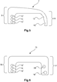
3 weitere perspektivische Darstellung des Halterahmens mit einem ersten Sperrelement in geschlossener Position, -
4 weitere perspektivische Darstellung des Halterahmens mit einem zweiten Sperrelement in geschlossener Position, -
5 eine Draufsicht auf ein Sperrelement, -
6 eine Draufsicht auf ein weiteres Sperrelement, -
7 eine perspektivische Darstellung eines mit Steckverbindermodulen bestückten Halterahmens mit einem ersten Sperrelement und -
8 eine perspektivische Ansicht eines Steckverbindermoduls.
-
1 2 shows a perspective illustration of a holding frame with a first locking element in the open position, -
2nd another perspective view of the holding frame with a second locking element in the open position, -
3rd another perspective view of the holding frame with a first locking element in the closed position, -
4th another perspective view of the holding frame with a second locking element in the closed position, -
5 a plan view of a locking element, -
6 a plan view of another locking element, -
7 a perspective view of a holding module equipped with connector modules with a first locking element and -
8th a perspective view of a connector module.
Die Figuren enthalten teilweise vereinfachte, schematische Darstellungen. Zum Teil werden für gleiche, aber gegebenenfalls nicht identische Elemente identische Bezugszeichen verwendet. Verschiedene Ansichten gleicher Elemente könnten unterschiedlich skaliert sein.The figures contain partially simplified, schematic representations. In some cases, identical reference numerals are used for identical but possibly not identical elements. Different views of the same elements could be scaled differently.
Die
An einer Stirnseite
Das Sperrelement
An einer Stirnseite
Die gegenüberliegenden Stirnseiten
Ein Schenkel
Der hier vorgestellte Halterahmen
In der Regel wird der Halterahmen in der geschlossenen Position beim Kunden angeliefert. Der Kunde wird das zweite Sperrelement
Eine Auslieferung des Halterahmens
Die geöffnete Position des Halterahmens
Mit offener Position ist gemeint, dass die Hälften entlang der Trennungslinie in einen Winkel α ungleich 180° zueinander stehen. Vorzugsweise liegt der Winkel zwischen 130° bis 170°. Ein Winkel zwischen 155° und 165° hat sich als besonders vorteilhaft erwiesen. In dieser Winkelstellung der Hälften können die Steckverbindermodule besonders leicht in den Halterahmen eingelegt werden. In der geschlossenen Position nehmen die Hälften einen Winkel von etwa 180° beziehungsweise genau 180° zueinander ein. Die Hälften stehen also in der geschlossenen Position parallel zueinander.An open position means that the halves are at an angle α not equal to 180 ° to one another along the dividing line. The angle is preferably between 130 ° to 170 °. An angle between 155 ° and 165 ° has proven to be particularly advantageous. In this angular position of the halves, the connector modules can be inserted particularly easily into the holding frame. In the closed position, the halves are at an angle of approximately 180 ° or exactly 180 ° to one another. The halves are parallel to each other in the closed position.
Steckverbindermodule
Zum Einfügen der Steckverbindermodule
Anschließend werden die Rahmenhälften
Der Halterahmen
Im Folgenden wird die Erfindung noch einmal kurz zusammengefasst: Die Erfindung betrifft einen Halterahmen (
BezugszeichenlisteReference list
- 11
- HalterahmenHolding frame
- 22nd
- GelenkkopfRod end
- 33rd
- GelenkaufnahmeJoint admission
- 44th
- Erste HälfteFirst half
- 55
- Zweite HälfteSecond half
- 66
- Erste StirnseiteFirst face
- 77
- Erstes SperrelementFirst locking element
- 88th
- Schraubescrew
- 99
- Schenkelleg
- 1010th
- Öffnungopening
- 1111
- Schenkelleg
- 1212th
- AussparungRecess
- 1313
- Zweite StirnseiteSecond face
- 1414
- Dornmandrel
- 1515
- Zweites SperrelementSecond locking element
- 1616
- Schenkelleg
- 1717th
- Schenkelleg
- 1818th
- Öffnungopening
- 1919th
- SteckverbindermodulConnector module
- 2020th
- HalterungsmittelBracket means
- 2121
- Federelastischer RasthakenSpring-elastic locking hook
- 2222
- SeitenteilSide panel
- 2323
- AusnehmungRecess
- 2424th
- ErdungsbuchseGrounding socket
Claims (10)
Priority Applications (5)
| Application Number | Priority Date | Filing Date | Title |
|---|---|---|---|
| DE102015114697.5A DE102015114697B4 (en) | 2015-09-03 | 2015-09-03 | Holding frame for connector modules |
| PCT/DE2016/100375 WO2017036450A1 (en) | 2015-09-03 | 2016-08-18 | Holding frame for plug connector modules having a locking bow that can be fastened |
| CN201680051302.9A CN107925190B (en) | 2015-09-03 | 2016-08-18 | Holding frame for a plug-in connector module with a fixable locking bow |
| EP16766471.3A EP3345256B1 (en) | 2015-09-03 | 2016-08-18 | Holding frame for plug connector modules having a locking bow that can be fastened |
| US15/755,024 US10333244B2 (en) | 2015-09-03 | 2016-08-18 | Holding frame for plug connector modules having a locking bow that can be fastened |
Applications Claiming Priority (1)
| Application Number | Priority Date | Filing Date | Title |
|---|---|---|---|
| DE102015114697.5A DE102015114697B4 (en) | 2015-09-03 | 2015-09-03 | Holding frame for connector modules |
Publications (2)
| Publication Number | Publication Date |
|---|---|
| DE102015114697A1 DE102015114697A1 (en) | 2017-03-09 |
| DE102015114697B4 true DE102015114697B4 (en) | 2020-03-26 |
Family
ID=56939828
Family Applications (1)
| Application Number | Title | Priority Date | Filing Date |
|---|---|---|---|
| DE102015114697.5A Active DE102015114697B4 (en) | 2015-09-03 | 2015-09-03 | Holding frame for connector modules |
Country Status (5)
| Country | Link |
|---|---|
| US (1) | US10333244B2 (en) |
| EP (1) | EP3345256B1 (en) |
| CN (1) | CN107925190B (en) |
| DE (1) | DE102015114697B4 (en) |
| WO (1) | WO2017036450A1 (en) |
Families Citing this family (12)
| Publication number | Priority date | Publication date | Assignee | Title |
|---|---|---|---|---|
| DE102015114699A1 (en) | 2015-09-03 | 2017-03-09 | Harting Electric Gmbh & Co. Kg | Holding frame for connector modules |
| DE102015114703B4 (en) | 2015-09-03 | 2020-03-26 | Harting Electric Gmbh & Co. Kg | Holding frame for connector modules |
| DE102015114700B4 (en) | 2015-09-03 | 2020-08-06 | Harting Electric Gmbh & Co. Kg | Holding frame |
| PL3345257T3 (en) | 2015-09-03 | 2021-03-08 | Harting Electric Gmbh & Co. Kg | Support frame for connector module |
| DE102015114696B4 (en) | 2015-09-03 | 2020-10-29 | Harting Electric Gmbh & Co. Kg | Holding frame for connector modules |
| DE102015114701B4 (en) | 2015-09-03 | 2019-01-31 | Harting Electric Gmbh & Co. Kg | Holding frame with blocking element |
| DE102016213251A1 (en) * | 2016-07-20 | 2018-01-25 | Harting Electric Gmbh & Co. Kg | Holding frame arrangement with base frame and fixing element and assembly process |
| DE102016213286A1 (en) | 2016-07-20 | 2018-01-25 | Harting Electric Gmbh & Co. Kg | Multi-part holding frame, assembly and assembly process |
| DE102017108432A1 (en) | 2017-04-20 | 2018-10-25 | Harting Electric Gmbh & Co. Kg | Holding frame for a connector and method of assembly |
| DE102017108433B4 (en) | 2017-04-20 | 2021-09-30 | Harting Electric Gmbh & Co. Kg | Holding frame for a connector and assembly method |
| DE102017129923A1 (en) * | 2017-11-24 | 2019-05-29 | Harting Electric Gmbh & Co. Kg | Grommet |
| DE102018115421A1 (en) * | 2018-06-27 | 2020-01-02 | Harting Electric Gmbh & Co. Kg | holding frame |
Citations (4)
| Publication number | Priority date | Publication date | Assignee | Title |
|---|---|---|---|---|
| DE19707120C1 (en) * | 1997-02-22 | 1998-06-25 | Harting Kgaa | Mounting frame for plug-in connector modules |
| CN201656162U (en) * | 2010-03-31 | 2010-11-24 | 厦门唯恩电气有限公司 | Fixing frame for connector |
| DE202012103360U1 (en) * | 2011-10-13 | 2013-01-15 | Weidmüller Interface GmbH & Co. KG | Holding frame for connectors |
| CN204205152U (en) * | 2014-10-20 | 2015-03-11 | 宁波欧科瑞连接器有限公司 | A kind of heavy-duty connector rotary self-locking fixed frame |
Family Cites Families (43)
| Publication number | Priority date | Publication date | Assignee | Title |
|---|---|---|---|---|
| US3160280A (en) | 1963-08-12 | 1964-12-08 | Gen Electric | Device for mounting apparatus |
| FR2148699A5 (en) | 1971-07-30 | 1973-03-23 | Socapex | |
| US4693440A (en) | 1986-07-07 | 1987-09-15 | Albert Lalonde | Refreshment cup holder |
| US5529426A (en) | 1991-10-24 | 1996-06-25 | Yazaki Corporation | Housing block-retaining construction |
| JP3147221B2 (en) | 1996-02-28 | 2001-03-19 | 矢崎総業株式会社 | Movable connection structure |
| JP3235489B2 (en) | 1996-11-14 | 2001-12-04 | 住友電装株式会社 | Block connector |
| DE19745384B4 (en) | 1997-10-14 | 2005-06-30 | The Whitaker Corp., Wilmington | Electrical connector assembly |
| US6196869B1 (en) | 1998-10-30 | 2001-03-06 | Lucent Technologies Inc. | Mounting bracket and power bus for a connector block |
| US6350141B1 (en) | 2000-05-30 | 2002-02-26 | Fci Americas Technology, Inc. | Connector frame for a high density electrical connector |
| US6692310B2 (en) | 2001-11-01 | 2004-02-17 | Molex Incorporated | Modular system for stacking electrical connector assemblies |
| DE20217273U1 (en) | 2002-11-09 | 2003-01-16 | Harting Electric Gmbh & Co Kg | Fastening device for connectors |
| TWM244598U (en) | 2003-09-26 | 2004-09-21 | Molex Taiwan Ltd | SIM card connector |
| US7056138B2 (en) | 2004-08-05 | 2006-06-06 | Tellabs Petaluma, Inc. | Retaining clip for Anderson-type power connectors |
| DE202005020026U1 (en) | 2005-12-22 | 2006-03-16 | Harting Electric Gmbh & Co. Kg | Holding frame for plug-in modules |
| JP4716123B2 (en) | 2006-06-16 | 2011-07-06 | 住友電装株式会社 | Connector cap holding structure |
| DE102007040496A1 (en) | 2007-08-21 | 2009-02-26 | Telegärtner Karl Gärtner GmbH | Cable connection device and connection device with such cable processing devices |
| CN101764314B (en) * | 2008-12-23 | 2012-10-31 | 富士康(昆山)电脑接插件有限公司 | Electric connector |
| ES2589914T3 (en) | 2009-12-09 | 2016-11-17 | Harting Electric Gmbh & Co. Kg | Plug-in connector for systems |
| PL2510590T3 (en) | 2009-12-09 | 2014-10-31 | Harting Electric Gmbh & Co Kg | System plug connector having an adapter module |
| DE202010002396U1 (en) * | 2010-02-16 | 2010-05-20 | Harting Electric Gmbh & Co. Kg | Electrical connector with locking bracket |
| CN101826665B (en) * | 2010-04-07 | 2011-11-16 | 辽宁省电力有限公司锦州供电公司 | Ground line device of power transmission line tower and hitching device thereof |
| US8449314B1 (en) * | 2010-12-22 | 2013-05-28 | Omnetics Connector Corporation | Latching system for electrical connector |
| CN202084755U (en) | 2011-04-28 | 2011-12-21 | 中航光电科技股份有限公司 | Connector module structure and fixed frame thereof |
| CN202335910U (en) | 2011-08-11 | 2012-07-18 | 朱君花 | Puncture lead crochet |
| DE102012110907B4 (en) | 2012-11-13 | 2019-06-13 | Harting Electric Gmbh & Co. Kg | Holding frame for holding connector modules |
| US8777676B1 (en) | 2012-12-21 | 2014-07-15 | Hubbell Incorporated | Universal mount contact block with reversible protected wiring terminals |
| US8821186B2 (en) | 2013-01-14 | 2014-09-02 | Cheng Uei Precision Industry Co., Ltd. | Universal serial bus connector |
| ITMI20130462A1 (en) | 2013-03-27 | 2014-09-28 | Westec S R L | STRUCTURE OF SUPPORTING FRAME FOR MODULAR CONNECTORS. |
| DE102013106279A1 (en) | 2013-06-17 | 2014-12-18 | Harting Electric Gmbh & Co. Kg | Holding frame for connector modules |
| DE202013103611U1 (en) | 2013-08-12 | 2013-09-19 | Harting Electric Gmbh & Co. Kg | Holding frame for connectors |
| CN106463877B (en) | 2014-04-02 | 2019-01-22 | 哈廷电子有限公司及两合公司 | Plug-in connector system |
| CN104466562B (en) | 2014-12-10 | 2017-07-21 | 资阳中车电气科技有限公司 | Connector modules fixed frame |
| CN204271392U (en) | 2014-12-10 | 2015-04-15 | 资阳南车电气有限公司 | Connector modules fixed frame |
| DE102015101433B3 (en) | 2015-02-02 | 2016-06-16 | Harting Electric Gmbh & Co. Kg | Holding frame for connector modules |
| DE102015114702B4 (en) | 2015-09-03 | 2019-01-31 | Harting Electric Gmbh & Co. Kg | holding frame |
| PL3345257T3 (en) | 2015-09-03 | 2021-03-08 | Harting Electric Gmbh & Co. Kg | Support frame for connector module |
| DE102015114696B4 (en) | 2015-09-03 | 2020-10-29 | Harting Electric Gmbh & Co. Kg | Holding frame for connector modules |
| DE102015216929A1 (en) * | 2015-09-03 | 2017-03-09 | Harting Electric Gmbh & Co. Kg | Holding frame for holding connector modules |
| DE102015114700B4 (en) | 2015-09-03 | 2020-08-06 | Harting Electric Gmbh & Co. Kg | Holding frame |
| DE102015114703B4 (en) | 2015-09-03 | 2020-03-26 | Harting Electric Gmbh & Co. Kg | Holding frame for connector modules |
| DE102015114701B4 (en) | 2015-09-03 | 2019-01-31 | Harting Electric Gmbh & Co. Kg | Holding frame with blocking element |
| DE102015114699A1 (en) | 2015-09-03 | 2017-03-09 | Harting Electric Gmbh & Co. Kg | Holding frame for connector modules |
| DE102015114698A1 (en) | 2015-09-03 | 2017-03-30 | Harting Electric Gmbh & Co. Kg | Holding frame for connector modules |
-
2015
- 2015-09-03 DE DE102015114697.5A patent/DE102015114697B4/en active Active
-
2016
- 2016-08-18 WO PCT/DE2016/100375 patent/WO2017036450A1/en active Application Filing
- 2016-08-18 CN CN201680051302.9A patent/CN107925190B/en active Active
- 2016-08-18 EP EP16766471.3A patent/EP3345256B1/en active Active
- 2016-08-18 US US15/755,024 patent/US10333244B2/en active Active
Patent Citations (4)
| Publication number | Priority date | Publication date | Assignee | Title |
|---|---|---|---|---|
| DE19707120C1 (en) * | 1997-02-22 | 1998-06-25 | Harting Kgaa | Mounting frame for plug-in connector modules |
| CN201656162U (en) * | 2010-03-31 | 2010-11-24 | 厦门唯恩电气有限公司 | Fixing frame for connector |
| DE202012103360U1 (en) * | 2011-10-13 | 2013-01-15 | Weidmüller Interface GmbH & Co. KG | Holding frame for connectors |
| CN204205152U (en) * | 2014-10-20 | 2015-03-11 | 宁波欧科瑞连接器有限公司 | A kind of heavy-duty connector rotary self-locking fixed frame |
Also Published As
| Publication number | Publication date |
|---|---|
| CN107925190B (en) | 2020-04-07 |
| EP3345256B1 (en) | 2019-10-09 |
| EP3345256A1 (en) | 2018-07-11 |
| US20180254577A1 (en) | 2018-09-06 |
| US10333244B2 (en) | 2019-06-25 |
| WO2017036450A1 (en) | 2017-03-09 |
| CN107925190A (en) | 2018-04-17 |
| DE102015114697A1 (en) | 2017-03-09 |
Similar Documents
| Publication | Publication Date | Title |
|---|---|---|
| DE102015114697B4 (en) | Holding frame for connector modules | |
| DE102015114703B4 (en) | Holding frame for connector modules | |
| EP3345259B1 (en) | Support frame for connector module | |
| EP3345257B1 (en) | Support frame for connector module | |
| EP3345251B1 (en) | Fixing frame for connector with a blade shaped fixing means | |
| EP3345253B1 (en) | Holding frame with restoring force for plug connector modules | |
| EP3345252B1 (en) | Holding frame comprising a fixing element held in a movable manner | |
| DE102011002135B4 (en) | Plug element with second contact fuse | |
| DE202008001842U1 (en) | plug-in device | |
| DE102014102793B4 (en) | Fastening element for a current sensor | |
| DE202016008409U1 (en) | Actuator for a connection device for electrical conductors | |
| EP2858186A1 (en) | Busbar adapter | |
| EP3406002B1 (en) | Holding frame with a guiding element for plug connector modules | |
| DE102018206849A1 (en) | Device for clamping attachment | |
| DE1933201A1 (en) | Device for the power transmission connection of electrical lines | |
| DE3151668A1 (en) | "CLUTCH DEVICE FOR A PHOTOGRAPHIC FLASHING DEVICE" | |
| DE2830640A1 (en) | TOY VEHICLE SECTION | |
| DE202022105103U1 (en) | Electronics module with integrated circuit board holder for contacting at least one wire with a printed circuit board that can be arranged in the circuit board holder | |
| DE102012216421B4 (en) | Arrangement, having a handle bridge and at least two electrical installation devices | |
| DE1817075C3 (en) | Clamping device for connecting at least two conductors | |
| DE8329459U1 (en) | Locking and ejecting device for electrical connectors | |
| DE752837C (en) | Counter or distribution board made of molded insulating material for electrical house electricity networks. like | |
| DE1204296B (en) | Device for earthing and short-circuiting overhead lines | |
| DE7601363U1 (en) | Explosion-proof connector clamp | |
| DE8409744U1 (en) | WOODEN CONNECTOR |
Legal Events
| Date | Code | Title | Description |
|---|---|---|---|
| R012 | Request for examination validly filed | ||
| R016 | Response to examination communication | ||
| R018 | Grant decision by examination section/examining division | ||
| R020 | Patent grant now final | ||
| R081 | Change of applicant/patentee |
Owner name: HARTING ELECTRIC STIFTUNG & CO. KG, DE Free format text: FORMER OWNER: HARTING ELECTRIC GMBH & CO. KG, 32339 ESPELKAMP, DE |