DE102015114696B4 - Holding frame for connector modules - Google Patents
Holding frame for connector modules Download PDFInfo
- Publication number
- DE102015114696B4 DE102015114696B4 DE102015114696.7A DE102015114696A DE102015114696B4 DE 102015114696 B4 DE102015114696 B4 DE 102015114696B4 DE 102015114696 A DE102015114696 A DE 102015114696A DE 102015114696 B4 DE102015114696 B4 DE 102015114696B4
- Authority
- DE
- Germany
- Prior art keywords
- holding frame
- locking element
- halves
- connector modules
- another
- Prior art date
- Legal status (The legal status is an assumption and is not a legal conclusion. Google has not performed a legal analysis and makes no representation as to the accuracy of the status listed.)
- Expired - Fee Related
Links
Images


Classifications
-
- H—ELECTRICITY
- H01—ELECTRIC ELEMENTS
- H01R—ELECTRICALLY-CONDUCTIVE CONNECTIONS; STRUCTURAL ASSOCIATIONS OF A PLURALITY OF MUTUALLY-INSULATED ELECTRICAL CONNECTING ELEMENTS; COUPLING DEVICES; CURRENT COLLECTORS
- H01R13/00—Details of coupling devices of the kinds covered by groups H01R12/70 or H01R24/00 - H01R33/00
- H01R13/46—Bases; Cases
- H01R13/502—Bases; Cases composed of different pieces
- H01R13/506—Bases; Cases composed of different pieces assembled by snap action of the parts
-
- H—ELECTRICITY
- H01—ELECTRIC ELEMENTS
- H01R—ELECTRICALLY-CONDUCTIVE CONNECTIONS; STRUCTURAL ASSOCIATIONS OF A PLURALITY OF MUTUALLY-INSULATED ELECTRICAL CONNECTING ELEMENTS; COUPLING DEVICES; CURRENT COLLECTORS
- H01R13/00—Details of coupling devices of the kinds covered by groups H01R12/70 or H01R24/00 - H01R33/00
- H01R13/46—Bases; Cases
- H01R13/502—Bases; Cases composed of different pieces
- H01R13/508—Bases; Cases composed of different pieces assembled by a separate clip or spring
-
- H—ELECTRICITY
- H01—ELECTRIC ELEMENTS
- H01R—ELECTRICALLY-CONDUCTIVE CONNECTIONS; STRUCTURAL ASSOCIATIONS OF A PLURALITY OF MUTUALLY-INSULATED ELECTRICAL CONNECTING ELEMENTS; COUPLING DEVICES; CURRENT COLLECTORS
- H01R13/00—Details of coupling devices of the kinds covered by groups H01R12/70 or H01R24/00 - H01R33/00
- H01R13/46—Bases; Cases
- H01R13/514—Bases; Cases composed as a modular blocks or assembly, i.e. composed of co-operating parts provided with contact members or holding contact members between them
-
- H—ELECTRICITY
- H01—ELECTRIC ELEMENTS
- H01R—ELECTRICALLY-CONDUCTIVE CONNECTIONS; STRUCTURAL ASSOCIATIONS OF A PLURALITY OF MUTUALLY-INSULATED ELECTRICAL CONNECTING ELEMENTS; COUPLING DEVICES; CURRENT COLLECTORS
- H01R13/00—Details of coupling devices of the kinds covered by groups H01R12/70 or H01R24/00 - H01R33/00
- H01R13/46—Bases; Cases
- H01R13/516—Means for holding or embracing insulating body, e.g. casing, hoods
- H01R13/518—Means for holding or embracing insulating body, e.g. casing, hoods for holding or embracing several coupling parts, e.g. frames
Landscapes
- Connector Housings Or Holding Contact Members (AREA)
- Details Of Connecting Devices For Male And Female Coupling (AREA)
Abstract
Halterahmen (1), in welchen Steckverbindermodule (19) einsetzbar sind, wobei der Halterahmen (1) aus zwei miteinander verbindbaren Hälften (4, 5), einer ersten Hälfte (4) und einer zweiten Hälfte (5), besteht, wobei der Halterahmen (1) endseitig jeweils einen Drehpunkt aufweist, wobei die Verbindungslinie der Drehpunkte eine Drehachse bildet, die parallel zu den Seitenflächen (22) der jeweiligen Hälften (4, 5) verläuft- wobei der Halterahmen (1) zumindest ein Sperrelement (7, 7') aufweist und- wobei die Hälften (4, 5) in zumindest zwei Positionen zueinander ausrichtbar sind. dadurch gekennzeichnet,- dass das erste Sperrelement (7) unter einer Vorspannung an den Hälften (4, 5) befestigt ist und die aus der Vorspannung resultierende Kraft auf die Endpunkte der Drehachse des Halterahmens wirkt- dass durch die Vorspannung eine Kraft ausgeübt wird, die den Halterahmen (1) in einer offenen Position oder in einer geschlossenen Position fixiert.Holding frame (1) in which connector modules (19) can be inserted, the holding frame (1) consisting of two halves (4, 5) that can be connected to one another, a first half (4) and a second half (5), the holding frame (1) each end has a pivot point, the connecting line of the pivot points forming an axis of rotation that runs parallel to the side surfaces (22) of the respective halves (4, 5) - the holding frame (1) having at least one locking element (7, 7 ') ) and- wherein the halves (4, 5) can be aligned with one another in at least two positions. characterized in that - that the first locking element (7) is attached to the halves (4, 5) under a prestress and the force resulting from the prestress acts on the end points of the axis of rotation of the holding frame - that the prestress exerts a force that the holding frame (1) fixed in an open position or in a closed position.
Description
Die Erfindung geht aus von einem Halterahmen für Steckverbindermodule nach dem Oberbegriff des unabhängigen Anspruchs 1.The invention is based on a holding frame for connector modules according to the preamble of
Derartige Halterahmen dienen zur Halterung von Steckverbindermodulen, wobei der Halterahmen mit verschiedenen Steckverbindermodulen bestückt und anschließend in ein Steckverbindergehäuse eingesetzt und mit diesem verschraubt wird. Dabei muss der Halterahmen mechanisch stabil sein, um den auftretenden Steck- und Ziehkräften beim Zusammenfügen beziehungsweise Trennen der Steckverbindung standhalten zu können.Such holding frames are used to hold connector modules, the holding frame being equipped with various connector modules and then inserted into a connector housing and screwed to it. The holding frame must be mechanically stable in order to be able to withstand the plugging and pulling forces that occur when the plug connection is joined or separated.
Stand der TechnikState of the art
Aus der
Der Halterahmen der
Bei erfolgreicher Bestückung des Halterahmens mit Steckverbindermodulen muss dieser in einen geschlossen Zustand beziehungsweise in eine geschlossene Position gebracht werden, damit die Steckverbindermodule fixiert sind. Für den geschlossenen Zustand des Halterahmens des Standes der Technik gibt es keinen fixierten geschlossenen Zustand, so dass sich der Halterahmen versehentlich öffnen kann, wodurch die Module aus ihrer Verankerung fallen können.When the holding frame is successfully equipped with connector modules, it must be brought into a closed state or into a closed position so that the connector modules are fixed. There is no fixed closed state for the closed state of the holding frame of the prior art, so that the holding frame can accidentally open, whereby the modules can fall out of their anchoring.
Durch eine reine gelenkige Verbindung besteht nicht immer ein definierter elektrischer Kontakt zwischen den Hälften des Halterahmens. Dadurch kann ein zuverlässiger Einsatz des Halterahmens zu Erdungszwecken nicht gewährleistet werden.Due to a purely articulated connection, there is not always a defined electrical contact between the halves of the holding frame. As a result, a reliable use of the holding frame for grounding purposes cannot be guaranteed.
Die
Die
Die
Insgesamt ist der Bestückungsprozess der
AufgabenstellungTask
Die Aufgabe der Erfindung besteht darin einen Halterahmen vorzuschlagen der einfach handhabbar und vielseitig einsetzbar ist.The object of the invention is to propose a holding frame that is easy to handle and versatile.
Die Aufgabe wird durch die kennzeichnenden Merkmale des unabhängigen Anspruchs 1 gelöst.The object is achieved by the characterizing features of
Vorteilhafte Ausgestaltungen der Erfindung sind in den Unteransprüchen angegeben.Advantageous embodiments of the invention are specified in the subclaims.
Der erfindungsgemäße Halterahmen ist dazu vorgesehen Steckverbindermodule aufzunehmen und anschließend in ein Steckverbindergehäuse eingebaut zu werden. Der Halterahmen besteht aus zwei miteinander verbindbaren Hälften, einer ersten Hälfte und einer zweiten Hälfte. Der Halterahmen weist zumindest ein erstes Sperrelement auf.The holding frame according to the invention is intended to accommodate connector modules and then to be installed in a connector housing. The holding frame consists of two halves that can be connected to one another, a first half and a second half. The holding frame has at least one first locking element.
Die Hälften sind in zumindest zwei Positionen zueinander ausrichtbar und über das erste Sperrelement in zumindest zwei Positionen zueinander fixierbar. Die Ausrichtbarkeit der Hälften wird über die gelenkige Verbindung erzielt, die weiter unten noch genauer beschrieben ist. The halves can be aligned with one another in at least two positions and can be fixed in at least two positions with one another via the first locking element. The alignability of the halves is achieved via the articulated connection, which is described in more detail below.
Vorteilhafterweise weist der Halterahmen endseitig jeweils einen Drehpunkt auf, wobei die Verbindungslinie der Drehpunkte eine Drehachse bildet, die parallel zu den Seitenflächen der Hälften verläuft. Entlang der Drehachse können die Hälften des Halterahmens gedreht und zueinander ausgerichtet werden. Die Drehpunkte werden in der Regel von einem Gelenkkopf gebildet, der in einer passenden Gelenkaufnahme geführt wird und weiter unten noch näher beschrieben ist.The holding frame advantageously has a pivot point at each end, the connecting line of the pivot points forming an axis of rotation which runs parallel to the side surfaces of the halves. The halves of the holding frame can be rotated along the axis of rotation and aligned with one another. The pivot points are usually formed by a joint head that is guided in a suitable joint receptacle and is described in more detail below.
Vorzugsweise weist das erste Sperrelement eine bogenförmige Form auf. Man könnte auch von einer U-Form sprechen. Ein Ende des Sperrelements ist an der ersten Hälfte und das andere Ende des Sperrelements ist an der zweiten Hälfte gehalten.Preferably the first locking element has an arcuate shape. One could also speak of a U-shape. One end of the locking element is held on the first half and the other end of the locking element is held on the second half.
Erfindungsgemäß ist das erste Sperrelement unter einer Vorspannung an den Hälften befestigt und durch die Vorspannung wird eine Kraft ausgeübt, die den Halterahmen in einer offenen Position oder in einer geschlossenen Position fixiert. Die durch die Vorspannung anliegende Kraft wird zur Fixierung des Halterahmens in einer geschlossenen oder einer offenen Position genutzt. Bei der Ausrichtung der Hälften muss der Benutzer zunächst eine Gegenkraft überwinden, bis der Halterahmen in die jeweilige Position (offen oder geschlossen) verbleibt beziehungsweise in dieser Position fixiert ist.According to the invention, the first locking element is attached to the halves under a pretension, and the pretension exerts a force which fixes the holding frame in an open position or in a closed position. The force applied by the preload is used to fix the holding frame in a closed or an open position. When aligning the halves, the user must first overcome a counterforce until the holding frame remains in the respective position (open or closed) or is fixed in this position.
Die aus der Vorspannung des ersten Sperrelements resultierende Kraft wirkt auf die stirnseitigen Gelenke beziehungsweise auf die Endpunkte der Drehachse des Halterahmens. Je nachdem in welcher Ausrichtung sich der Halterahmen gerade befindet, wirkt eine resultierende Kraft auf die gelenkige Verbindung und zwingt den Halterahmen in eine geschlossene oder offene Position.The force resulting from the pretensioning of the first locking element acts on the end joints or on the end points of the axis of rotation of the holding frame. Depending on the orientation in which the holding frame is currently located, a resulting force acts on the articulated connection and forces the holding frame into a closed or open position.
Vorzugsweise weist der Halterahmen zumindest ein zweites Sperrelement auf. Vorzugsweise ist das erste Sperrelement an einer Stirnfläche des Halterahmens angeordnet ist und das zweite Sperrelement ist an der gegenüberliegenden Stirnfläche des Halterahmens angeordnet. Das erste Sperrelement befindet sich auf der Innenseite der ersten Stirnfläche des Halterahmens. Das zweite Sperrelement befindet sich auf der Innenseite der zweiten Stirnfläche des Halterahmens. Dadurch ist der Halterahmen mechanisch stabil in seiner Ausrichtungsmöglichkeit.The holding frame preferably has at least one second locking element. The first locking element is preferably arranged on one end face of the holding frame and the second locking element is arranged on the opposite end face of the holding frame. The first locking element is located on the inside of the first end face of the holding frame. The second locking element is located on the inside of the second end face of the holding frame. As a result, the holding frame is mechanically stable in its alignment option.
Vorzugsweise ist das zweite Sperrelement meanderförmig ausgebildet. Diese Meanderform unterstützt die Ausrichtbewegung der Hälften.The second locking element is preferably designed in a meander shape. This meander shape supports the alignment movement of the halves.
Besonders vorteilhaft ist es wenn auch das zweite Sperrelement unter einer Vorspannung an den Hälften befestigt ist. Diese Vorspannung kann die Fixierung durch das erste Sperrelement unterstützen.It is particularly advantageous if the second locking element is also attached to the halves under a bias. This bias can support the fixation by the first locking element.
Vorteilhafterweise bestehen die Hälften aus einem metallischen Material. In einem geschlossenen Zustand stehen die Hälften in einem elektrisch leitenden Kontakt zueinander. Die elektrisch leitende Verbindung zwischen den Hälften kann auch durch das Sperrelement bewirkt beziehungsweise unterstützt werden. Dazu muss das Sperrelement beziehungsweise müssen die Sperrelemente ebenfalls aus einem elektrisch leitenden Material bestehen.The halves are advantageously made of a metallic material. In a closed state, the halves are in electrically conductive contact with one another. The electrically conductive connection between the halves can also be brought about or supported by the blocking element. For this purpose, the blocking element or the blocking elements must also consist of an electrically conductive material.
Mit offener Position ist gemeint, dass die Hälften entlang der Trennungslinie in einen Winkel α ungleich 180° zueinander stehen. Vorzugsweise liegt der Winkel zwischen 130° bis 170°. Ein Winkel zwischen 155° und 165° hat sich als besonders vorteilhaft erwiesen. In dieser Winkelstellung der Hälften können die Steckverbindermodule besonders leicht in den Halterahmen eingelegt werden. In der geschlossenen Position nehmen die Hälften einen Winkel von etwa 180° beziehungsweise genau 180° zueinander ein. Die Hälften stehen also in der geschlossenen Position parallel zueinander.The open position means that the halves are at an angle α other than 180 ° to one another along the dividing line. The angle is preferably between 130 ° and 170 °. An angle between 155 ° and 165 ° has proven to be particularly advantageous. In this angular position of the halves, the connector modules can be inserted particularly easily into the holding frame. In the closed position, the halves make an angle of approximately 180 ° or exactly 180 ° to one another. The halves are parallel to each other in the closed position.
Über das Sperrelement werden die beiden Hälften zuverlässig in elektrischen Kontakt zueinander gebracht. Dies geschieht zum einen über das Sperrelement selbst, sofern es aus einem elektrisch leitenden Material gefertigt ist. Außerdem wird durch die Vorspannung des Sperrelements der Gelenkkopf einer Hälfte in die Gelenkaufnahme der anderen Hälfte gedrückt, wodurch ein zuverlässiger elektrischer Kontakt entsteht.The two halves are reliably brought into electrical contact with one another via the locking element. This is done on the one hand via the locking element itself, provided it is made of an electrically conductive material. In addition, the pretensioning of the locking element presses the joint head of one half into the joint receptacle of the other half, creating a reliable electrical contact.
FigurenlisteFigure list
Ein Ausführungsbeispiel der Erfindung ist in den Zeichnungen dargestellt und wird im Folgenden näher erläutert. Es zeigen:
-
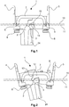
1 eine Seitenansicht eines Halterahmens mit einem ersten - Sperrelement in einer geschlossenen Position,
-
2 eine Seitenansicht eines Halterahmens mit einem ersten - Sperrelement in einer offenen Position,
-
3 eine perspektivische Darstellung eines Ausschnitts des Halterahmens mit einem ersten Sperrelement in einer offenen Position, -
4 eine perspektivische Darstellung eines weiteren Ausschnitts des Halterahmens mit einem zweiten Sperrelement in einer offenen Position, -
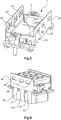
5 eine perspektivische Darstellung des geschlossenen Halterahmens mit einem ersten Sperrelement, -
6 eine perspektivische Darstellung des geschlossenen Halterahmens mit integrierten Steckverbindermodulen, -
7 eine perspektivische Darstellung eines ersten Sperrelements und -
8 eine perspektivische Darstellung eines zweiten Sperrelements.
-
1 a side view of a support frame with a first - Locking element in a closed position,
-
2 a side view of a support frame with a first - Locking element in an open position,
-
3 a perspective view of a section of the holding frame with a first locking element in an open position, -
4th a perspective view of a further section of the holding frame with a second locking element in an open position, -
5 a perspective view of the closed holding frame with a first locking element, -
6 a perspective view of the closed holding frame with integrated connector modules, -
7th a perspective view of a first locking element and -
8th a perspective view of a second locking element.
Die Figuren enthalten teilweise vereinfachte, schematische Darstellungen. Zum Teil werden für gleiche, aber gegebenenfalls nicht identische Elemente identische Bezugszeichen verwendet. Verschiedene Ansichten gleicher Elemente könnten unterschiedlich skaliert sein.The figures contain partially simplified, schematic representations. In some cases, identical reference symbols are used for identical, but possibly not identical elements. Different views of the same elements could be scaled differently.
Die
Der Halterahmen
Die Hälften
Das erste Sperrelement
Im Folgenden wird die Funktionsweise des ersten Sperrelements
Befindet sich die Spannungslinie
Auf einer gegenüberliegenden, innenliegenden Stirnseite des Halterahmens
Steckverbindermodule
Der Halterahmen
Der Kern der Erfindung bezieht sich auf einen Halterahmen
Es hat sich als besonders effektiv herausgestellt, wenn ein Halterahmen
BezugszeichenlisteList of reference symbols
- 11
- HalterahmenHolding frame
- 22
- GelenkkopfSwivel head
- 33
- GelenkaufnahmeJoint mount
- 44th
- Erste HälfteFirst half
- 55
- Zweite HälfteSecond half
- 66th
- AusnehmungRecess
- 77th
- Erstes SperrelementFirst locking element
- 7'7 '
- Zweites Sperrelement Second locking element
- 88th
- Schraubescrew
- 99
- RasthakenLocking hook
- 1010
- SpannungslinieTension line
- 1111
- MittellinieCenter line
- 1212
- Erster Anschlag des GelenkkopfesFirst stop of the joint head
- 1313th
- Erster Anschlag der ersten HälfteFirst stop of the first half
- 1414th
- Zweiter Anschlag des Gelenkkopfes Second stop of the joint head
- 1515th
- Zweiter Anschlag der ersten Hälfte Second attack in the first half
- 1919th
- SteckverbindermodulConnector module
- 2020th
- HalterungsmittelHolding means
- 2121st
- Federelastischer Rasthaken Spring-elastic locking hook
- 2222nd
- SeitenteilSide part
- 2323
- Öffnungopening
- 2424
- ErdungsbuchseGrounding socket
Claims (8)
Priority Applications (15)
| Application Number | Priority Date | Filing Date | Title |
|---|---|---|---|
| DE102015114696.7A DE102015114696B4 (en) | 2015-09-03 | 2015-09-03 | Holding frame for connector modules |
| US15/755,042 US10276968B2 (en) | 2015-09-03 | 2016-05-30 | Holding frame for plug connector modules |
| KR1020187008923A KR102067192B1 (en) | 2015-09-03 | 2016-05-30 | Gripping frame for plug connector module |
| RU2018111699A RU2689123C1 (en) | 2015-09-03 | 2016-05-30 | Retaining frame for plug-in connector modules |
| PL16733872T PL3345257T3 (en) | 2015-09-03 | 2016-05-30 | Support frame for connector module |
| EP16733872.2A EP3345257B1 (en) | 2015-09-03 | 2016-05-30 | Support frame for connector module |
| CN201680051292.9A CN108028491B (en) | 2015-09-03 | 2016-05-30 | Holding frame for a plug-in connector module |
| PCT/DE2016/100249 WO2017036439A1 (en) | 2015-09-03 | 2016-05-30 | Holding frame for plug connector modules |
| RU2018111697A RU2689159C1 (en) | 2015-09-03 | 2016-08-17 | Retaining frame for plug-in connector modules, having shutoff element under pre-stress |
| EP16774846.6A EP3345259B1 (en) | 2015-09-03 | 2016-08-17 | Support frame for connector module |
| PL16774846T PL3345259T3 (en) | 2015-09-03 | 2016-08-17 | Support frame for connector module |
| KR1020187008922A KR102057651B1 (en) | 2015-09-03 | 2016-08-17 | Holding frame for plug connector module with locking member under preload |
| CN201680051273.6A CN107925193B (en) | 2015-09-03 | 2016-08-17 | Holding frame for a plug-in connector module with a locking element under pretensioning |
| PCT/DE2016/100368 WO2017036447A1 (en) | 2015-09-03 | 2016-08-17 | Holding frame for plug-in connector modules with a locking element under prestress |
| US15/754,567 US10276965B2 (en) | 2015-09-03 | 2016-08-17 | Holding frame for plug-in connector modules with a locking element under prestress |
Applications Claiming Priority (1)
| Application Number | Priority Date | Filing Date | Title |
|---|---|---|---|
| DE102015114696.7A DE102015114696B4 (en) | 2015-09-03 | 2015-09-03 | Holding frame for connector modules |
Publications (2)
| Publication Number | Publication Date |
|---|---|
| DE102015114696A1 DE102015114696A1 (en) | 2017-03-09 |
| DE102015114696B4 true DE102015114696B4 (en) | 2020-10-29 |
Family
ID=57044850
Family Applications (1)
| Application Number | Title | Priority Date | Filing Date |
|---|---|---|---|
| DE102015114696.7A Expired - Fee Related DE102015114696B4 (en) | 2015-09-03 | 2015-09-03 | Holding frame for connector modules |
Country Status (8)
| Country | Link |
|---|---|
| US (1) | US10276965B2 (en) |
| EP (1) | EP3345259B1 (en) |
| KR (1) | KR102057651B1 (en) |
| CN (1) | CN107925193B (en) |
| DE (1) | DE102015114696B4 (en) |
| PL (1) | PL3345259T3 (en) |
| RU (1) | RU2689159C1 (en) |
| WO (1) | WO2017036447A1 (en) |
Families Citing this family (11)
| Publication number | Priority date | Publication date | Assignee | Title |
|---|---|---|---|---|
| DE102015114699A1 (en) | 2015-09-03 | 2017-03-09 | Harting Electric Gmbh & Co. Kg | Holding frame for connector modules |
| DE102015114697B4 (en) | 2015-09-03 | 2020-03-26 | Harting Electric Gmbh & Co. Kg | Holding frame for connector modules |
| DE102015114703B4 (en) | 2015-09-03 | 2020-03-26 | Harting Electric Gmbh & Co. Kg | Holding frame for connector modules |
| DE102015114700B4 (en) | 2015-09-03 | 2020-08-06 | Harting Electric Gmbh & Co. Kg | Holding frame |
| PL3345257T3 (en) | 2015-09-03 | 2021-03-08 | Harting Electric Gmbh & Co. Kg | Support frame for connector module |
| DE102015114701B4 (en) | 2015-09-03 | 2019-01-31 | Harting Electric Gmbh & Co. Kg | Holding frame with blocking element |
| DE102016100794B4 (en) * | 2016-01-19 | 2019-03-28 | Harting Electric Gmbh & Co. Kg | Support frame with guide element for connector modules and system consisting of two of these support frames |
| DE102017108432A1 (en) | 2017-04-20 | 2018-10-25 | Harting Electric Gmbh & Co. Kg | Holding frame for a connector and method of assembly |
| DE102017108433B4 (en) | 2017-04-20 | 2021-09-30 | Harting Electric Gmbh & Co. Kg | Holding frame for a connector and assembly method |
| DE102017125859A1 (en) * | 2017-11-06 | 2019-05-09 | Harting Electric Gmbh & Co. Kg | Modular mounting frame for connectors |
| DE202021102455U1 (en) | 2020-07-31 | 2021-05-26 | Inkonn (Suzhou) Electric Technology Co., Ltd. | Assemblable connector combination frame |
Citations (4)
| Publication number | Priority date | Publication date | Assignee | Title |
|---|---|---|---|---|
| DE19707120C1 (en) * | 1997-02-22 | 1998-06-25 | Harting Kgaa | Mounting frame for plug-in connector modules |
| CN201656162U (en) * | 2010-03-31 | 2010-11-24 | 厦门唯恩电气有限公司 | Fixing frame for connector |
| DE202012103360U1 (en) * | 2011-10-13 | 2013-01-15 | Weidmüller Interface GmbH & Co. KG | Holding frame for connectors |
| CN204205152U (en) * | 2014-10-20 | 2015-03-11 | 宁波欧科瑞连接器有限公司 | A kind of heavy-duty connector rotary self-locking fixed frame |
Family Cites Families (45)
| Publication number | Priority date | Publication date | Assignee | Title |
|---|---|---|---|---|
| US3160280A (en) | 1963-08-12 | 1964-12-08 | Gen Electric | Device for mounting apparatus |
| FR2148699A5 (en) | 1971-07-30 | 1973-03-23 | Socapex | |
| US4693440A (en) | 1986-07-07 | 1987-09-15 | Albert Lalonde | Refreshment cup holder |
| US5529426A (en) | 1991-10-24 | 1996-06-25 | Yazaki Corporation | Housing block-retaining construction |
| JP3147221B2 (en) | 1996-02-28 | 2001-03-19 | 矢崎総業株式会社 | Movable connection structure |
| JP3235489B2 (en) | 1996-11-14 | 2001-12-04 | 住友電装株式会社 | Block connector |
| DE19745384B4 (en) | 1997-10-14 | 2005-06-30 | The Whitaker Corp., Wilmington | Electrical connector assembly |
| US6196869B1 (en) | 1998-10-30 | 2001-03-06 | Lucent Technologies Inc. | Mounting bracket and power bus for a connector block |
| US6350141B1 (en) | 2000-05-30 | 2002-02-26 | Fci Americas Technology, Inc. | Connector frame for a high density electrical connector |
| US6692310B2 (en) | 2001-11-01 | 2004-02-17 | Molex Incorporated | Modular system for stacking electrical connector assemblies |
| DE20217273U1 (en) | 2002-11-09 | 2003-01-16 | Harting Electric Gmbh & Co Kg | Fastening device for connectors |
| TWM244598U (en) | 2003-09-26 | 2004-09-21 | Molex Taiwan Ltd | SIM card connector |
| US7056138B2 (en) | 2004-08-05 | 2006-06-06 | Tellabs Petaluma, Inc. | Retaining clip for Anderson-type power connectors |
| DE202005020026U1 (en) | 2005-12-22 | 2006-03-16 | Harting Electric Gmbh & Co. Kg | Holding frame for plug-in modules |
| JP4716123B2 (en) | 2006-06-16 | 2011-07-06 | 住友電装株式会社 | Connector cap holding structure |
| DE102007040496A1 (en) | 2007-08-21 | 2009-02-26 | Telegärtner Karl Gärtner GmbH | Cable connection device and connection device with such cable processing devices |
| JP5346530B2 (en) * | 2008-09-24 | 2013-11-20 | 株式会社三桂製作所 | Holding frame for connector module |
| RU82943U1 (en) * | 2008-12-18 | 2009-05-10 | Открытое Акционерное Общество "Российские Железные Дороги" | DEVICE FOR CLOSING OR OPENING CONTACTS |
| CN101764314B (en) | 2008-12-23 | 2012-10-31 | 富士康(昆山)电脑接插件有限公司 | Electric connector |
| ES2589914T3 (en) | 2009-12-09 | 2016-11-17 | Harting Electric Gmbh & Co. Kg | Plug-in connector for systems |
| PL2510590T3 (en) | 2009-12-09 | 2014-10-31 | Harting Electric Gmbh & Co Kg | System plug connector having an adapter module |
| DE202010002396U1 (en) | 2010-02-16 | 2010-05-20 | Harting Electric Gmbh & Co. Kg | Electrical connector with locking bracket |
| US8449314B1 (en) | 2010-12-22 | 2013-05-28 | Omnetics Connector Corporation | Latching system for electrical connector |
| CN202084755U (en) | 2011-04-28 | 2011-12-21 | 中航光电科技股份有限公司 | Connector module structure and fixed frame thereof |
| CN202352910U (en) | 2011-12-15 | 2012-07-25 | 四川华丰企业集团有限公司 | Novel rectangle movable frame used for heavy load connector |
| DE102012102685B4 (en) * | 2012-03-28 | 2024-02-01 | Dr. Ing. H.C. F. Porsche Aktiengesellschaft | Device for holding a container for a charging socket in a motor vehicle |
| DE102012110907B4 (en) | 2012-11-13 | 2019-06-13 | Harting Electric Gmbh & Co. Kg | Holding frame for holding connector modules |
| US8777676B1 (en) * | 2012-12-21 | 2014-07-15 | Hubbell Incorporated | Universal mount contact block with reversible protected wiring terminals |
| US8821186B2 (en) | 2013-01-14 | 2014-09-02 | Cheng Uei Precision Industry Co., Ltd. | Universal serial bus connector |
| ITMI20130462A1 (en) | 2013-03-27 | 2014-09-28 | Westec S R L | STRUCTURE OF SUPPORTING FRAME FOR MODULAR CONNECTORS. |
| DE102013106279A1 (en) | 2013-06-17 | 2014-12-18 | Harting Electric Gmbh & Co. Kg | Holding frame for connector modules |
| DE202013103611U1 (en) | 2013-08-12 | 2013-09-19 | Harting Electric Gmbh & Co. Kg | Holding frame for connectors |
| CN106463877B (en) | 2014-04-02 | 2019-01-22 | 哈廷电子有限公司及两合公司 | Plug-in connector system |
| CN104466562B (en) | 2014-12-10 | 2017-07-21 | 资阳中车电气科技有限公司 | Connector modules fixed frame |
| CN204271392U (en) | 2014-12-10 | 2015-04-15 | 资阳南车电气有限公司 | Connector modules fixed frame |
| DE102015101433B3 (en) | 2015-02-02 | 2016-06-16 | Harting Electric Gmbh & Co. Kg | Holding frame for connector modules |
| DE102015114702B4 (en) | 2015-09-03 | 2019-01-31 | Harting Electric Gmbh & Co. Kg | holding frame |
| DE102015114700B4 (en) | 2015-09-03 | 2020-08-06 | Harting Electric Gmbh & Co. Kg | Holding frame |
| DE102015114703B4 (en) | 2015-09-03 | 2020-03-26 | Harting Electric Gmbh & Co. Kg | Holding frame for connector modules |
| DE102015216929A1 (en) * | 2015-09-03 | 2017-03-09 | Harting Electric Gmbh & Co. Kg | Holding frame for holding connector modules |
| DE102015114701B4 (en) | 2015-09-03 | 2019-01-31 | Harting Electric Gmbh & Co. Kg | Holding frame with blocking element |
| PL3345257T3 (en) | 2015-09-03 | 2021-03-08 | Harting Electric Gmbh & Co. Kg | Support frame for connector module |
| DE102015114697B4 (en) | 2015-09-03 | 2020-03-26 | Harting Electric Gmbh & Co. Kg | Holding frame for connector modules |
| DE102015114699A1 (en) | 2015-09-03 | 2017-03-09 | Harting Electric Gmbh & Co. Kg | Holding frame for connector modules |
| DE102015114698A1 (en) | 2015-09-03 | 2017-03-30 | Harting Electric Gmbh & Co. Kg | Holding frame for connector modules |
-
2015
- 2015-09-03 DE DE102015114696.7A patent/DE102015114696B4/en not_active Expired - Fee Related
-
2016
- 2016-08-17 KR KR1020187008922A patent/KR102057651B1/en active IP Right Grant
- 2016-08-17 CN CN201680051273.6A patent/CN107925193B/en active Active
- 2016-08-17 EP EP16774846.6A patent/EP3345259B1/en active Active
- 2016-08-17 WO PCT/DE2016/100368 patent/WO2017036447A1/en active Application Filing
- 2016-08-17 US US15/754,567 patent/US10276965B2/en active Active
- 2016-08-17 RU RU2018111697A patent/RU2689159C1/en active
- 2016-08-17 PL PL16774846T patent/PL3345259T3/en unknown
Patent Citations (4)
| Publication number | Priority date | Publication date | Assignee | Title |
|---|---|---|---|---|
| DE19707120C1 (en) * | 1997-02-22 | 1998-06-25 | Harting Kgaa | Mounting frame for plug-in connector modules |
| CN201656162U (en) * | 2010-03-31 | 2010-11-24 | 厦门唯恩电气有限公司 | Fixing frame for connector |
| DE202012103360U1 (en) * | 2011-10-13 | 2013-01-15 | Weidmüller Interface GmbH & Co. KG | Holding frame for connectors |
| CN204205152U (en) * | 2014-10-20 | 2015-03-11 | 宁波欧科瑞连接器有限公司 | A kind of heavy-duty connector rotary self-locking fixed frame |
Also Published As
| Publication number | Publication date |
|---|---|
| PL3345259T3 (en) | 2020-10-19 |
| WO2017036447A1 (en) | 2017-03-09 |
| KR20180048865A (en) | 2018-05-10 |
| CN107925193A (en) | 2018-04-17 |
| US20180248296A1 (en) | 2018-08-30 |
| US10276965B2 (en) | 2019-04-30 |
| EP3345259B1 (en) | 2020-01-01 |
| KR102057651B1 (en) | 2019-12-20 |
| EP3345259A1 (en) | 2018-07-11 |
| DE102015114696A1 (en) | 2017-03-09 |
| RU2689159C1 (en) | 2019-05-24 |
| CN107925193B (en) | 2020-02-28 |
Similar Documents
| Publication | Publication Date | Title |
|---|---|---|
| DE102015114696B4 (en) | Holding frame for connector modules | |
| DE102015114703B4 (en) | Holding frame for connector modules | |
| EP3345257B1 (en) | Support frame for connector module | |
| DE102015114697B4 (en) | Holding frame for connector modules | |
| DE2209688C3 (en) | Insert nut | |
| EP3345253B1 (en) | Holding frame with restoring force for plug connector modules | |
| EP3345251B1 (en) | Fixing frame for connector with a blade shaped fixing means | |
| DE202009002324U1 (en) | Terminal for connecting conductor ends | |
| DE4408985B4 (en) | Electrical device, in particular terminal block, with a terminal for a quick connection | |
| EP3345252A1 (en) | Holding frame comprising a fixing element held in a movable manner | |
| DE2210904B2 (en) | Electrical socket | |
| DD139779A5 (en) | CABLE PROCESSING WITH PULL RELIEF | |
| DE2901213C2 (en) | Detachable pin connection for components | |
| DE102004061046B4 (en) | Case closure device | |
| DE102008015374B4 (en) | Electrical terminal | |
| DE60131217T2 (en) | Electrical spring connection | |
| WO2003103098A1 (en) | Contact element for an electric plug connection | |
| EP3602697A1 (en) | Mounting frame comprising a pe contact | |
| DE3715358A1 (en) | Electrical installation apparatus, especially a plug socket | |
| DE202009011828U1 (en) | Electric spring clamp | |
| DE19719433C2 (en) | Connector housing | |
| DE8311706U1 (en) | TURN LOCK FOR CONNECTING CONTAINERS | |
| DE8409744U1 (en) | WOODEN CONNECTOR | |
| DE1817075B2 (en) | Busbar and cable connector - connects at least two conductors using U-shaped straps and screw plate | |
| DE2355699B2 (en) | Connector for pipes |
Legal Events
| Date | Code | Title | Description |
|---|---|---|---|
| R012 | Request for examination validly filed | ||
| R016 | Response to examination communication | ||
| R018 | Grant decision by examination section/examining division | ||
| R020 | Patent grant now final | ||
| R119 | Application deemed withdrawn, or ip right lapsed, due to non-payment of renewal fee |