CN1742358A - Method and system for fabricating multi layer devices on a substrate - Google Patents
Method and system for fabricating multi layer devices on a substrate Download PDFInfo
- Publication number
- CN1742358A CN1742358A CNA2003801090448A CN200380109044A CN1742358A CN 1742358 A CN1742358 A CN 1742358A CN A2003801090448 A CNA2003801090448 A CN A2003801090448A CN 200380109044 A CN200380109044 A CN 200380109044A CN 1742358 A CN1742358 A CN 1742358A
- Authority
- CN
- China
- Prior art keywords
- semiconductor layer
- layer
- bonded areas
- bonding
- crystal grain
- Prior art date
- Legal status (The legal status is an assumption and is not a legal conclusion. Google has not performed a legal analysis and makes no representation as to the accuracy of the status listed.)
- Pending
Links
Images


Classifications
-
- H—ELECTRICITY
- H01—ELECTRIC ELEMENTS
- H01L—SEMICONDUCTOR DEVICES NOT COVERED BY CLASS H10
- H01L22/00—Testing or measuring during manufacture or treatment; Reliability measurements, i.e. testing of parts without further processing to modify the parts as such; Structural arrangements therefor
- H01L22/20—Sequence of activities consisting of a plurality of measurements, corrections, marking or sorting steps
-
- H—ELECTRICITY
- H01—ELECTRIC ELEMENTS
- H01L—SEMICONDUCTOR DEVICES NOT COVERED BY CLASS H10
- H01L21/00—Processes or apparatus adapted for the manufacture or treatment of semiconductor or solid state devices or of parts thereof
- H01L21/02—Manufacture or treatment of semiconductor devices or of parts thereof
- H01L21/04—Manufacture or treatment of semiconductor devices or of parts thereof the devices having at least one potential-jump barrier or surface barrier, e.g. PN junction, depletion layer or carrier concentration layer
- H01L21/18—Manufacture or treatment of semiconductor devices or of parts thereof the devices having at least one potential-jump barrier or surface barrier, e.g. PN junction, depletion layer or carrier concentration layer the devices having semiconductor bodies comprising elements of Group IV of the Periodic System or AIIIBV compounds with or without impurities, e.g. doping materials
- H01L21/30—Treatment of semiconductor bodies using processes or apparatus not provided for in groups H01L21/20 - H01L21/26
-
- B—PERFORMING OPERATIONS; TRANSPORTING
- B81—MICROSTRUCTURAL TECHNOLOGY
- B81C—PROCESSES OR APPARATUS SPECIALLY ADAPTED FOR THE MANUFACTURE OR TREATMENT OF MICROSTRUCTURAL DEVICES OR SYSTEMS
- B81C99/00—Subject matter not provided for in other groups of this subclass
- B81C99/0035—Testing
- B81C99/0045—End test of the packaged device
-
- H—ELECTRICITY
- H01—ELECTRIC ELEMENTS
- H01L—SEMICONDUCTOR DEVICES NOT COVERED BY CLASS H10
- H01L22/00—Testing or measuring during manufacture or treatment; Reliability measurements, i.e. testing of parts without further processing to modify the parts as such; Structural arrangements therefor
- H01L22/10—Measuring as part of the manufacturing process
- H01L22/14—Measuring as part of the manufacturing process for electrical parameters, e.g. resistance, deep-levels, CV, diffusions by electrical means
-
- H—ELECTRICITY
- H01—ELECTRIC ELEMENTS
- H01L—SEMICONDUCTOR DEVICES NOT COVERED BY CLASS H10
- H01L2224/00—Indexing scheme for arrangements for connecting or disconnecting semiconductor or solid-state bodies and methods related thereto as covered by H01L24/00
- H01L2224/01—Means for bonding being attached to, or being formed on, the surface to be connected, e.g. chip-to-package, die-attach, "first-level" interconnects; Manufacturing methods related thereto
- H01L2224/10—Bump connectors; Manufacturing methods related thereto
- H01L2224/12—Structure, shape, material or disposition of the bump connectors prior to the connecting process
- H01L2224/13—Structure, shape, material or disposition of the bump connectors prior to the connecting process of an individual bump connector
-
- H—ELECTRICITY
- H01—ELECTRIC ELEMENTS
- H01L—SEMICONDUCTOR DEVICES NOT COVERED BY CLASS H10
- H01L2224/00—Indexing scheme for arrangements for connecting or disconnecting semiconductor or solid-state bodies and methods related thereto as covered by H01L24/00
- H01L2224/01—Means for bonding being attached to, or being formed on, the surface to be connected, e.g. chip-to-package, die-attach, "first-level" interconnects; Manufacturing methods related thereto
- H01L2224/10—Bump connectors; Manufacturing methods related thereto
- H01L2224/15—Structure, shape, material or disposition of the bump connectors after the connecting process
- H01L2224/16—Structure, shape, material or disposition of the bump connectors after the connecting process of an individual bump connector
-
- H—ELECTRICITY
- H01—ELECTRIC ELEMENTS
- H01L—SEMICONDUCTOR DEVICES NOT COVERED BY CLASS H10
- H01L2924/00—Indexing scheme for arrangements or methods for connecting or disconnecting semiconductor or solid-state bodies as covered by H01L24/00
- H01L2924/013—Alloys
- H01L2924/014—Solder alloys
-
- H—ELECTRICITY
- H01—ELECTRIC ELEMENTS
- H01L—SEMICONDUCTOR DEVICES NOT COVERED BY CLASS H10
- H01L2924/00—Indexing scheme for arrangements or methods for connecting or disconnecting semiconductor or solid-state bodies as covered by H01L24/00
- H01L2924/10—Details of semiconductor or other solid state devices to be connected
- H01L2924/11—Device type
- H01L2924/13—Discrete devices, e.g. 3 terminal devices
- H01L2924/1304—Transistor
- H01L2924/1305—Bipolar Junction Transistor [BJT]
-
- H—ELECTRICITY
- H01—ELECTRIC ELEMENTS
- H01L—SEMICONDUCTOR DEVICES NOT COVERED BY CLASS H10
- H01L2924/00—Indexing scheme for arrangements or methods for connecting or disconnecting semiconductor or solid-state bodies as covered by H01L24/00
- H01L2924/10—Details of semiconductor or other solid state devices to be connected
- H01L2924/11—Device type
- H01L2924/13—Discrete devices, e.g. 3 terminal devices
- H01L2924/1304—Transistor
- H01L2924/1306—Field-effect transistor [FET]
- H01L2924/13091—Metal-Oxide-Semiconductor Field-Effect Transistor [MOSFET]
Abstract
A method for fabricating multi layer active devices on a bulk substrate is disclosed. Multi layer microelectromechanical and microfluidic devices are fabricated on a substrate with layers of predetermined weak and strong bond regions where deconstructed layers of devices at or on the weak bond regions. Multi layer integrated circuits are fabricated on a substrate with layers of predetermined weak and strong bond regions is disclosed. An arbitrary number of layers can be bonded and stacked to create a predetermined device on the substrate. Also disclosed are methods of creating edge interconnects and vias through the substrate to form interconnections between layers and devices thereon.
Description
The cross reference of related application
The application requires the U.S. Provisional Patent Application No.60/428 that submitted on November 20th, 2002 according to 35U.S.C. § 119 (e), 125 priority, and this application is incorporated herein by reference.
Technical field
The present invention is relevant for the method and system of making the multilayer active device on substrate, particularly about a kind of vertical integrated circuit, micro electro mechanical device and microfluidic device made on semiconductor substrate.
Background technology
Demand for quicker and more cheap integrated circuit continues to increase.More's law infers that the number of transistors of every square of inch can be with double ratio growth in every year.Yet, when the manufacturing method of chip of traditional two-dimensional space (or plane) reaches capacity, in order to realize the prophesy of More's law, the frontier that certainly will will innovate technologies and make with extended chip.
Until now, most of suffer from comes from the active device that continues to dwindle on the opposite planar structure being manufactured in to the demand of intensive integrated circuits more.That is, two-dimentional chip manufacturing is the common method of making for semiconductor already.Most semiconductor equipment is fabricated in the single crystalline semiconductor substrate on a plane.And this mode to be set to three dimensions real very limited for vertical long-pending.
When being on the verge of the limit in two-dimentional chip manufacturing space, the key breakthrough on the usefulness will be toward three dimensions chip manufacturing development (that is the chip manufacturing on the z direction).
Micro element is vertical long-pending if storehouse in same encapsulation, is a kind of encapsulation volume, increase current densities, saving substrate space and increase usefulness and functional quite attracting method of reducing.The delay of reduction inside chip and power consumption are the long-pending two kinds of advantages of establishing of storehouse.If these device attenuation and storehouse are on the top of each other, the advantage aspect cost and current densities is with jumbo increase.And in IC (integrated circuit) and MEMS (MEMS (micro electro mechanical system)) two processing procedures, the silicon wafer third dimension space overwhelming majority is still untapped.
The present method of used two-dimensional device vertical stack on the industry, the action that is generally chip-scaling law and need be dependent on mill makes the wafer attenuation.Most method is dependent on the mutual contact mode that utilizes through hole, storehouse mothers and sons chip or routing bonding.Present method all has the restriction of impacting about package size, cost, reliability and output.Although the difficulty, the storehouse device with reach three-dimensional integration be found to be feasible, especially aspect MEMS (micro electro mechanical system) (MEMS) and application-oriented integrated circuit (ASIC) controller.The high density internal memory encapsulation of storehouse individual chip has been found many specific application.
The U.S. Patent No. 6,355,501 of IBM has disclosed a kind of method of making the three dimensional integrated circuits assembly, relates generally to chip-scale.Wherein the assembly of Jie Shiing is made up of three-dimensional storehouse silicon (SOI) chip on insulator, and has disclosed a kind of method that forms this kind integrated circuit assembly.Each soi chip comprises that getting the portion of putting (handler) for one comes the first metallization pattern is made Mechanical Contact to do electric the contact with semiconductor device.This metallization pattern contacts second metallization pattern on the opposed surface that is arranged on semiconductor equipment successively.Method in this announcement comprises that step has: a) make a substrate have one the 3rd metallization pattern on the one first surface; B) mat make soi chip second metallization pattern and substrate the 3rd metallized pattern is electric contacts, a wherein soi chip of substrate first surface is alignd at the first surface of substrate; C) remove the portion of putting of getting from this soi chip, expose the first metallization pattern of soi chip; D) make the alignment of second soi chip and first soi chip, what allow second metallization pattern and first soi chip of second soi chip be exposed out first metallizes that pattern is electric to be contacted; And e) repeated steps c) and d) come one to be stacked in one and upward to install follow-up soi chip.Yet, this reference disclose method can function be limited for fear of the cost costliness.
The critical defect of the method that is disclosed in above-mentioned U.S. Patent No. 6,355,501 is that the three-dimensional circuit that forms that its applicant emphasizes causes poor efficiency on a wafer-scale.In addition, aim at each chip and be considered to be the major issue that hinders the wafer-scale storehouse.The storehouse step of each chip comprises aims at desire layer body bonded to one another.Must have transparent adhesion and window and can be accessed in two lip-deep alignment marks that desire is bonding optically.In addition, getting the portion of putting must be permeable for alignment mark.Other shortcoming is relevant with the quantity of follow-up repetition methods step.According to description wherein, for reaching the electric contact between the stack layer body, when it by storehouse and alignment the time, carry out a solder reflow step between each layer body.After refluxing, chip stack is the edge bonding again.Again, before layer afterwards can be bonded, get the portion of putting must with sticking remove (with laser or other hot gas), polishing, and other preparation process remove.At last, excessive substrate removes with worn or etching off.
These unfavorable conditions cause cost and functional relevant shortcoming.Follow worn expenses, loaded down with trivial details subsequent step, the chip-scale of overslaugh wafer-scale storehouse, and among the well known cost that reduces of wafer-scale, the storehouse that desire to overcome on so the production problems on the wafer revert to the problem of chip-scale, number of plies restriction causes a greater number, storehouse must be on other storehouse storehouse, since follow-up storehouse amount with interconnected relevant make whole output minimizing, multiple return flow again can undermine other layer.And functional unfavorable conditions comprises: lack diagnosis, lack interconnected variability, limited interconnected space, the limited addressability of large-scale storehouse, particularly internal memory storehouse, do not integrate the ability of noise shielding, do not integrate heat dissipation capability, do not have ability, and the limit of layer body quantity of ground plane.
California, USA Irving's Irvine Sensors company and IBM Corporation have adopted and have implemented a kind of three-dimension packaging.Discontinuous crystal grain utilizes the marginal swell method by storehouse and interconnected.Known non-defective unit crystal grain (KGD) is by attenuation.The solder pump at crystal grain edge is being used to align and the interconnected crystal grain that connects storehouse.One crystal grain is to be placed in the epoxy matrix.Epoxy helps the crystal grain of alignment different size, and is used as interconnected surface.The demand of the interconnected and KGD of individual storehouse and crystal grain, causing this is a kind of very expensive manufacture method.
Another known employing three-dimension packaging be Cubic Memory company, the said firm produces high density storehouse memory modules by using the interconnection paths of the gold that is arranged in the several strata sulphur imido insulator layers on the entire wafer.Yet storehouse and vertical interconnect are still on other chip-scale one by one.
The another kind of again three-dimension packaging embodiment that has adopted is that Tessera company and the Intel company by the California, USA Joseph of Arimathea, Saint together developed at chip-scale, by seeing through microballoon grid array the storehouse that chip is adhered on the adaptability substrate is encapsulated, and z is to the chip loaded ribbon that is folded on the itself.
Ziptronix company is developing the IC of wafer-scale storehouse apparently.It is conceived to challenge aligning, stress management, heat management, high density and productivity ratio.
Illustrate as top institute, feasible vertical long-pending equipment, method still has various defective.A kind of basic defect comes from loss in productivity.All device stack modes are crystal grain-scale on the current market.And even prepare other crystal grain, alignment, storehouse connection.So method is very expensive, and the production loss of storehouse is the mixing production loss for each device in the layer body.The production loss that the tolerable sometimes of cheap device increases similarly is a SRAM storehouse etc.But when at the more expensive device of storehouse, solution is for using a known non-defective unit crystal grain (KGD).KGD means, through each unpackaged crystal grain burned and test.In addition, storehouse need be finished after electric test at every layer.This processing process institute is must expense very expensive, and main application has been limited in the user of high-order, similarly is army and satellite technology.
The vertical long-pending unfavorable conditions of establishing of another tradition is started in the technology of crystal grain scale limited.Except Ziptronix did not reach the mode in market as yet, all methods all were that the storehouse device is on a crystal grain scale.Wafer-scale make the remarkable economical advantage with these technology be do fully less than.The high cost of handling and testing individual die limits these methods and is used for the high-order application.
Another known problem that forms circuit in whole traditional fabrication schedule is the demand of getting the portion of putting that is supported on the substrate.When handling, substrate must provide mechanical support and heat stability.Processed substrate thereby must be enough thick in to resist abominable processing environment comprises high pressure, temperature and chemistry and energy exposure.If seek active thin-film device then need further to handle.
After formation circuit or other structure are resisted processing on the enough thick substrate, take a kind of processing mode, promptly remove the thickness of substrate with the method for machinery.The method of machinery, such as cut-out or grinding etc., resource and manpower that waste is whole.Cut off or worn material not recyclable usually, even callable, before reusing, necessarily need go through further and handle.In addition, the substrate of attenuation is normally subject to polishing or other method is come smooth surface.Other technology forms an etching stopping layer structure before being included in the device manufacturing on substrate.Yet, still before an etching step of selecting, being removed on the substrate typical case by worn mechanical type, etching substrates is to etching stopping layer as this step 1.These all technology cause the waste of time and resource, and the quality control of making us keeping in mind.
The another kind of technology that forms thin-film device is utilized ion implantation method.A kind of generally utilization that ion is implanted is to form several layers of thin semi-conducting material.For instance, the method is disclosed among patent application EP 01045448 and the WO 00/024059, both " implant separation method by hydrogen ion and make the method for SOI wafer and the SOI wafer of producing with this method " all by name, and the both is as a reference in this application.Ion especially similarly is hydrogen ion or helium ion, implants at the end face of silicon wafer.Ion is implanted a degree of depth at top surface., can from bulk silicon substrate layering go out skim body, generally be limited by high temperature (about more than 500 ℃) and handle down thereafter.This thin layer then can be held on an edge body layer and a substrate by holder, and microelectronics or other structure can be formed on it.Yet microelectronics must form after the layering thin layer, is to influence nocuously because ion is implanted microelectronics.Particularly thin layer can be distorted, and device can be implanted and damage by ion, or device can be compromised during layering.
The patent application WO 98/33209 of Bruel etc.; be named as " method that in particular semiconductor, comprises a protected ion zone and relate to the acquisition film of ion implantation ", wherein disclosed the method that the film that comprises a metal-oxide semiconductor (MOS) (MOS) is provided.Substantially, a MOS transistor is formed on the surface of semiconductor substrate.Transistorized zone is conductively-closed, and zone on every side is to implant with ion to define expection geosutures (that is, being produced by the ion implantation step at this place's microvesicle).For above will separating transistorized film is arranged, the action that near the expection geosutures microvesicle set about disconnecting, and the Jinping's face (that is, not having microvesicle to exist) that sees through below the transistor is propagated.Well imagine and have transistorized film thereon to utilize the announcement of patent application WO98/33209 be feasible, but, because the crystalline structure of baseplate material certainly will make broken action extremely near transistor, and make transistor be subjected to disconnecting the influence of the undesirable pressure of propagation.
The U.S. Patent No. 6,103,597 of Aspar etc., name are called " method that obtains semiconductor material thin film ", have mainly disclosed the content that makes a film substrate that wherein has microelectronics or other structure be subjected to ionic bombardment.The microvesicle of gas forms in the degree of depth that forms the definition film thickness.Yet multiple microelectronics that can be formed on substrate and structure need a follow-up malleableize step, are distributed to the shortcoming of described element with repairing infringement or other.Therefore, thin layer is disclosed as a kind of can being caused can separating from beneath baseplate material along the heat treatment of microvesicle line fragmentation.
The name of Sakaguchi etc. is called the U.S. Patent No. 6 of " substrate and relative manufacturing process ", 221,738 and name be called the U.S. Patent No. 6,100 of the method for object " produce semiconductor ", 166 disclose the semiconductor layer of bonding infiltration, and both all are used as reference herein.The strength that wherein discloses the bonding permeable formation a little less than, so promote to use removing of an external strength.U.S. Patent No. 6,100,166 disclose a layer body can a strength that divest direction remove.Yet that is disclosed in these two referenced patent cases utilizes faint permeability and separation physical action between whole layer body interface.This can injure structural intergrity in the middle of it and the semiconductor equipment on any semi-conducting material that is formed on infiltration to integral body.
The U.S. Patent No. 6,184,111 of Henley etc. by name " preceding system semiconductor program implant and back processing procedure preface divided thin film from " in this application as a reference.Its degree of depth once selecting that has disclosed under a silicon water surface is utilized a shell of compression.Device is formed on above the shell of compression.Usually according to wafer diameter change dosage and in identical implanting on rank.The one deck above the beginning separating pressure layer is propagated in controlled disconnection, comprises device any on it.Attention forms the method for shell of compression can damage the device that it forms above, the repairing malleableize step after so generally still needing.Therefore, traditional ion implant and layered approach in, the film that comprises shadow microelectronics or other structure thereon be can not be under the situation that does not distort or damage this thin semiconductor layer implanting ions.
Therefore, consider the unfavorable conditions of current processing of circuit, a kind of shortcoming of avoiding unfavorable conditions and conventional method and will be desirable providing three-dimensional integrated circuit on the chip or on a wafer-scale.
Therefore, an elementary object of the present invention is to provide the three dimensions integrated circuit of a least cost.
Further object of the present invention provides a multilager base plate and makes a useful device.
Another object of the present invention provides the method and system that increases productivity ratio into vertical integrated device.
Another purpose again of the present invention provides the method and system of the vertical integrated device of classification.
Read following description and follow accompanying drawing, purpose that the present invention is above-mentioned and illustrated thereafter and advantage can be understood.
Summary of the invention
The front is discussed and other problem, known unfavorable conditions, and purpose that the present invention reached in advance, will overcome and solution by disclosed certain methods and device.
In one aspect, invention is a method of making vertical micro electro mechanical device, and the step of composing method comprises: a monolith substrate that is provided on the wafer (is shown structure base board, bulksubstrate); The one first selection bonding semiconductor layer of vertical bearing on this substrate, this bonding semiconductor layer comprises weak bonded areas and strong bonded areas; Vertical bearing is in this first one second selection bonding semiconductor layer of selecting on the bonding semiconductor layer; Wherein an electrode and can encourage (actuatable) element to be based upon this weak bonded areas place or a little less than this on bonded areas; Wherein but this electrode is configured to toward each other with this exciting element; But and wherein this electrode with should exciting element vertically cross over this and first select bonding semiconductor layer and this second to select the bonding semiconductor layer.
In another aspect, the present invention is vertical mems device, and it comprises: the monolith substrate on a wafer; The one first selection bonding semiconductor layer of vertical bearing on this substrate, this bonding semiconductor layer comprises weak bonded areas and strong bonded areas; Vertical bearing is in this first one second selection bonding semiconductor layer of selecting on the bonding semiconductor layer; Wherein but an electrode and an exciting element are based upon this weak bonded areas place or a little less than this on bonded areas; Wherein but this electrode is configured to toward each other with this exciting element; But and wherein this electrode with should exciting element vertically cross over this and first select bonding semiconductor layer and this second to select the bonding semiconductor layer.
In another aspect, the present invention is a kind of vertical mems device that is formed on the crystal grain, and it comprises: the monolith substrate on a wafer; The one first selection bonding semiconductor layer of vertical bearing on this substrate, this bonding semiconductor layer comprises weak bonded areas and strong bonded areas; Vertical bearing is in this first one second selection bonding semiconductor layer of selecting on the bonding semiconductor layer; Wherein but an element and an exciting element are based upon this weak bonded areas place or a little less than this on bonded areas; Wherein but an element and an exciting element are based upon this weak bonded areas place or a little less than this on bonded areas; Wherein but this element is configured to toward each other with this exciting element; But and wherein this element with should exciting element vertically cross over this and first select bonding semiconductor layer and this second to select the bonding semiconductor layer.
In another aspect, the present invention is about a kind of method that is used to make the multilayer microfluidic device, and it may further comprise the steps: a monolith substrate is provided; On this substrate, optionally set up strong bonded areas and weak bonded areas; First tack coat of vertical bearing on this substrate is provided; Set up a port on this first tack coat, this port is corresponding to bonded areas a little less than this; Mechanically create a passage and be coupled to this port; Remove this ground floor from this monolith substrate; And this ground floor to one second layer that bonds.
In another aspect, the present invention is about a kind of multilayer microfluidic device, and it comprises: the monolith substrate on a wafer; The one first selection tack coat of vertical bearing on this substrate, this tack coat comprises weak bonded areas and strong bonded areas; Vertical bearing is in this first one second selection tack coat of selecting on the tack coat; Wherein destructing port and destructing passage build on described weak bonded areas place or on described weak bonded areas; And wherein said port and this first selection tack coat of described channel vertical ground leap and this second selection tack coat.
In another aspect, the present invention is about a kind of multilayer microfluidic device that is forming on the crystal grain: the monolith substrate on a wafer; The one first selection tack coat of vertical bearing on this substrate, this tack coat comprises weak bonded areas and strong bonded areas; Vertical bearing is in this first one second selection tack coat of selecting on the tack coat; Wherein destructing port and destructing passage build on described weak bonded areas place or on described weak bonded areas; This first selection tack coat and this second selection tack coat are crossed in wherein said port and described channel vertical ground; And wherein this crystal grain is formed by the described bonding semiconductor layer of cutting.
In another aspect, the present invention is a method of making a vertical micro electro mechanical device, and the step of composing method comprises: be provided at the monolith substrate on the wafer; The one first selection bonding semiconductor layer of vertical bearing on this substrate, this bonding semiconductor layer comprises weak bonded areas and strong bonded areas; Vertical bearing is in this first one second selection bonding semiconductor layer of selecting on the bonding semiconductor layer; Wherein but an electrode and an exciting element are based upon this weak bonded areas place or a little less than this on bonded areas; Wherein but this electrode is configured to toward each other with this exciting element; But and wherein this electrode with should exciting element vertically cross over this and first select bonding semiconductor layer and this second to select the bonding semiconductor layer.
In another aspect, the present invention is vertical mems device, and it comprises: the monolith substrate on a wafer; The one first selection bonding semiconductor layer of vertical bearing on this substrate, this bonding semiconductor layer comprises weak bonded areas and strong bonded areas; Vertical bearing is in this first one second selection bonding semiconductor layer of selecting on the bonding semiconductor layer; Wherein but an electrode and an exciting element are based upon this weak bonded areas place or a little less than this on bonded areas; Wherein but this electrode is configured to toward each other with this exciting element; But and wherein this electrode with should exciting element vertically cross over this and first select bonding semiconductor layer and this second to select the bonding semiconductor layer.
In another aspect, the present invention is a kind of vertical mems device that is formed on the crystal grain, and it comprises: the monolith substrate on a wafer; The one first selection bonding semiconductor layer of vertical bearing on this substrate, this bonding semiconductor layer comprises weak bonded areas and strong bonded areas; Vertical bearing is in this first one second selection bonding semiconductor layer of selecting on the bonding semiconductor layer; Wherein but an element and an exciting element are based upon this weak bonded areas place or a little less than this on bonded areas; Wherein but an element and an exciting element are based upon this weak bonded areas place or a little less than this on bonded areas; Wherein but this element is configured to toward each other with this exciting element; But and wherein this element with should exciting element vertically cross over this and first select bonding semiconductor layer and this second to select the bonding semiconductor layer.
In another aspect, the present invention is a kind of method that is used to improve the productivity ratio of being scheduled to device, and this device is made up of one or more multilayer crystal grain, and this method may further comprise the steps: the functional layer quantity of each described multilayer crystal grain is judged on diagnostic ground; And the described functional layer quantity of foundation is classified to each described multilayer crystal grain.
In another aspect, the present invention is the method for a kind of known non-defective unit layer that makes a device have at least one predetermined quantity (known good layer), this device is made up of one or more multilayer crystal grain, and this method may further comprise the steps: the functional layer quantity of each described multilayer crystal grain is judged on diagnostic ground; According to described functional layer quantity each multilayer crystal granules sorted is arrived a plurality of storage areas, each storage area has relevant known non-defective unit layer minimum number; Select in the multilayer crystal grain of the known non-defective unit layer with this predetermined quantity from one of them storage area, this storage area has the relevant known non-defective unit layer minimum number that equals known non-defective unit layer predetermined quantity at least.
In another aspect, the present invention is a kind of method that the device of the known non-defective unit layer with at least one predetermined quantity is provided, this device is made up of one or more multilayer crystal grain, and this method may further comprise the steps: the functional layer quantity of each described multilayer crystal grain is judged on diagnostic ground; According to described functional layer quantity each multilayer crystal granules sorted is arrived a plurality of storage areas, each storage area has relevant known non-defective unit layer minimum number; Select a plurality of described multilayer crystal grain, their known non-defective unit number of plies amount summation equals known non-defective unit layer predetermined quantity at least; And forming a combination crystal grain in conjunction with a plurality of multilayer crystal grain of described selection, this combination crystal grain has the known non-defective unit number of plies amount that equals known non-defective unit layer predetermined quantity at least.
In another aspect, the present invention is a kind of method that the device of the known non-defective unit layer with at least one predetermined quantity is provided, this device is made up of one or more multilayer crystal grain, and this method may further comprise the steps: the respectively functional layer quantity of this multilayer crystal grain is judged on diagnostic ground; Quantity according to described functional layer arrives a plurality of storage areas with each multilayer crystal granules sorted, and each storage area has relevant known non-defective unit layer minimum number; Select a multilayer crystal grain from described multilayer crystal grain, the more known non-defective unit layer of described known non-defective unit number of plies amount predetermined quantity is many; And the multilayer crystal grain that cuts this selection forms one first multilayer crystal grain part and one second multilayer crystal grain part, and the known non-defective unit number of plies amount of this first multilayer crystal grain part equals known non-defective unit layer predetermined quantity at least; This second multilayer crystal grain partly is classified to a described storage area, and this storage area has the corresponding known non-defective unit layer minimum number of known non-defective unit number of plies amount with second multilayer crystal grain part.
In another aspect, the present invention is a kind of method that a plurality of wafer stacks are classified, and wherein each wafer stack comprises a plurality of vertical integrated devices, said method comprising the steps of: one on the wafer or all devices are diagnosed; And described wafer stack is classified according to the quantity of the vertical integrated device that will be cut successively that has the known non-defective unit layer of predetermined quantity in the wafer stack.
In another aspect, the present invention is a kind of method that a plurality of wafer stacks are classified, and wherein each wafer stack comprises a plurality of vertical integrated devices, said method comprising the steps of: one on the wafer or all devices are diagnosed; And described wafer stack is classified according to the known non-defective unit layer minimum number of all described devices that comprised on this wafer stack.
In another aspect, the present invention is a kind of method of making vertical integrated circuit, and this method may further comprise the steps: a monolith substrate is provided, and this monolith substrate comprises the oxide skin(coating) of burying underground; On this substrate, selectively set up strong bonded areas and weak bonded areas; Provide and vertically be carried on the bonding of first on this substrate semiconductor layer; Set up the semiconductor device part on this first bonding semiconductor layer, this semiconductor device part is corresponding to bonded areas a little less than this; Remove this first semiconductor layer from this monolith substrate; And this first semiconductor layer is bonded to one second semiconductor layer.
In another aspect, the present invention is a kind of method of making vertical integrated circuit, and this method may further comprise the steps: a monolith substrate is provided; On this substrate, optionally set up strong bonded areas and weak bonded areas; The first bonding semiconductor layer of vertical bearing on this substrate is provided; Set up the semiconductor device part on this first bonding semiconductor layer, described semiconductor device part is corresponding to described weak bonded areas; Between this first semiconductor layer and this monolith substrate, form an oxide skin(coating) of burying underground at the interface; Remove this first semiconductor layer from this monolith substrate; And this first semiconductor layer is bonded to one second semiconductor layer.
In another aspect, the present invention is a kind of method of making vertical micro electro mechanical device, and this method may further comprise the steps: a monolith substrate is provided, and this monolith substrate comprises the oxide skin(coating) of burying underground; On this substrate, optionally set up strong bonded areas and weak bonded areas; The first bonding semiconductor layer of vertical bearing on this substrate is provided; Set up an electrode on this first bonding semiconductor layer, this electrode is corresponding to described weak bonded areas; But set up one and be configured to the exciting element relative with this electrode; Remove this first semiconductor layer from this monolith substrate; And this first semiconductor layer is bonded to one second semiconductor layer.
In another aspect, the present invention is a kind of method that is used to make vertical micro electro mechanical device, and this method may further comprise the steps: a monolith substrate is provided, and this monolith substrate comprises the oxide skin(coating) of burying underground; On this substrate, optionally set up strong bonded areas and weak bonded areas; The first bonding semiconductor layer of vertical bearing on this substrate is provided; Set up an electrode on this first bonding semiconductor layer, this electrode is corresponding to described weak bonded areas; But set up one and be configured to the exciting element relative with this electrode; Between this first semiconductor layer and this monolith substrate, form an oxide skin(coating) of burying underground at the interface; Remove this first semiconductor layer from this monolith substrate; And this first semiconductor layer is bonded to one second semiconductor layer.
In another aspect, the present invention is a kind of method of making vertical micro electro mechanical device, and this method may further comprise the steps: a monolith substrate is provided, and this monolith substrate comprises the oxide skin(coating) of burying underground; On this substrate, optionally set up strong bonded areas and weak bonded areas; First tack coat of vertical bearing on this substrate is provided; Set up a port on this first tack coat, this port is corresponding to bonded areas a little less than this; Mechanically create a passage and be coupled to this port; Remove this ground floor from this monolith substrate; And this ground floor to one second layer that bonds.
In another aspect, the present invention is a kind of method of making the multilayer microfluidic device, and this method may further comprise the steps: a monolith substrate is provided; On this substrate, optionally set up strong bonded areas and weak bonded areas; The first bonding semiconductor layer of vertical bearing on this substrate is provided; Between this first tack coat and this monolith substrate, form an oxide skin(coating) of burying underground at the interface; Set up a port on this first tack coat, this port is corresponding to bonded areas a little less than this; Mechanically create a passage and be coupled to this port; Remove this ground floor from this monolith substrate; And this ground floor to one second layer that bonds.
Description of drawings
Read following detailed description together with appended accompanying drawing, summary noted earlier and preferred embodiment of the present invention will more be understood.Demonstrate preferable accompanying drawing and embodiment herein.Yet will be appreciated that the present invention is not limited to the form that accompanying drawing is painted, and accompanying drawing just helps to understand the present invention.In the accompanying drawings, wherein:
Fig. 1 is an optionally schematic sectional view of bonding multiple substrate of foundation principle of the present invention;
Fig. 2 is an optionally schematic sectional view of bonding multiple substrate of foundation principle of the present invention;
Fig. 3 is an optionally schematic sectional view of bonding multiple substrate of foundation principle of the present invention;
Fig. 4 is an optionally schematic sectional view of bonding multiple substrate of foundation principle of the present invention;
Fig. 5 is an optionally schematic sectional view of bonding multiple substrate of foundation principle of the present invention;
Fig. 6 is an optionally schematic sectional view of bonding multiple substrate of foundation principle of the present invention;
Fig. 7 is an optionally schematic sectional view of bonding multiple substrate of foundation principle of the present invention;
Fig. 8 is a schematic sectional view selecting caking property ground multilager base plate according to principle of the present invention;
Fig. 9 is a schematic sectional view selecting the bonding multiple substrate according to principle of the present invention;
Figure 10 is a schematic sectional view selecting the bonding multiple substrate according to principle of the present invention;
Figure 11 is a schematic sectional view selecting the bonding multiple substrate according to principle of the present invention;
Figure 12 is a schematic sectional view selecting the bonding multiple substrate according to principle of the present invention;
Figure 13 is a schematic sectional view selecting the bonding multiple substrate according to principle of the present invention;
Figure 14 is a horizontal cross according to the geometry in the wafer bonding zone of principle of the present invention;
Figure 15 is a horizontal cross according to the geometry in the wafer bonding zone of principle of the present invention;
Figure 16 is a horizontal cross according to the geometry in the wafer bonding zone of principle of the present invention;
Figure 17 is a horizontal cross according to the geometry in the wafer bonding zone of principle of the present invention;
Figure 18 is a horizontal cross according to the geometry in the wafer bonding zone of principle of the present invention;
Figure 19 is a horizontal cross according to the geometry in the wafer bonding zone of principle of the present invention;
Figure 20 is a horizontal cross according to the geometry in the wafer bonding zone of principle of the present invention;
Figure 21 is the schematic sectional view according to a kind of wafer de bonding technology of principle of the present invention;
Figure 22 is the schematic sectional view according to a kind of wafer de bonding technology of principle of the present invention;
Figure 23 is the schematic sectional view according to a kind of wafer de bonding technology of principle of the present invention;
Figure 24 is the schematic sectional view according to a kind of wafer de bonding technology of principle of the present invention;
Figure 25 is the schematic sectional view according to a kind of wafer de bonding technology of principle of the present invention;
Figure 26 is the schematic sectional view according to a kind of wafer de bonding technology of principle of the present invention;
Figure 27 is the schematic sectional view according to a kind of wafer de bonding technology of principle of the present invention;
Figure 28 is the schematic sectional view according to a kind of wafer de bonding technology of principle of the present invention;
Figure 29 is the schematic sectional view according to a kind of wafer de bonding technology of principle of the present invention;
Figure 30 is the schematic sectional view according to a kind of wafer de bonding technology of principle of the present invention;
Figure 31 is the schematic sectional view according to a kind of wafer de bonding technology of principle of the present invention;
Figure 32 is the schematic sectional view according to a kind of wafer de bonding technology of principle of the present invention;
Figure 33 is the schematic sectional view according to a kind of wafer de bonding technology of principle of the present invention;
Figure 34 is a schematic sectional view according to the circuit part of principle of the present invention;
Figure 35 is according to a substrate of principle of the present invention and gets the schematic sectional view of the portion of putting;
Figure 36 is according to a principle of the present invention alignment and stack circuit part schematic sectional view with conductor;
Figure 37 is according to a principle of the present invention alignment and stack circuit part schematic sectional view with conductor;
Figure 38 is according to a principle of the present invention alignment and stack circuit part schematic sectional view with conductor;
Figure 39 is according to a schematic sectional view of the circuit part of principle of the present invention;
Figure 40 is according to a principle of the present invention alignment and stack circuit part schematic sectional view with conductor;
Figure 41 is according to a principle of the present invention alignment and stack circuit part schematic sectional view with conductor;
Figure 42 is according to a schematic sectional view of the circuit part of principle of the present invention;
Figure 43 is according to a principle of the present invention alignment and stack circuit part schematic sectional view with conductor;
Figure 44 is according to a principle of the present invention alignment and stack circuit part schematic sectional view with conductor;
Figure 45 is according to a principle of the present invention alignment and stack circuit part schematic sectional view with conductor;
Figure 46 is according to a schematic sectional view of the circuit part of principle of the present invention;
Figure 47 is according to a schematic sectional view of the circuit part of principle of the present invention;
Figure 48 is according to a schematic sectional view of the circuit part of principle of the present invention;
Figure 49 is according to a schematic sectional view of the circuit part of principle of the present invention;
Figure 50 is according to a principle of the present invention alignment and stack circuit part schematic sectional view with conductor;
Figure 51 is according to a principle of the present invention alignment and stack circuit part schematic sectional view with conductor;
Figure 52 is according to a principle of the present invention alignment and stack circuit part schematic sectional view with conductor;
Figure 53 is according to a principle of the present invention alignment and stack circuit part schematic sectional view with conductor;
Figure 54 is according to a principle of the present invention alignment and stack circuit part schematic sectional view with conductor;
Figure 55 is according to a principle of the present invention alignment and stack circuit part schematic sectional view with conductor;
Figure 56 is according to a principle of the present invention alignment and stack circuit part schematic sectional view with conductor;
Figure 57 is according to a principle of the present invention alignment and stack circuit part schematic sectional view with conductor;
Figure 58 is a schematic sectional view according to principle alignment of the present invention and stack circuit part;
Figure 59 is a schematic sectional view according to principle alignment of the present invention and stack circuit part;
The interconnected schematic sectional view with circuit part of Figure 60 according to the edge of principle of the present invention;
Figure 61 is the interconnected schematic sectional view of edge according to principle of the present invention;
Figure 62 is the interconnected schematic sectional view of edge according to principle of the present invention;
Figure 63 is aligned and a schematic sectional view of the circuit part of storehouse according to principle of the present invention;
Figure 64 is aligned and a schematic sectional view of the circuit part of storehouse according to principle of the present invention;
Figure 65 is by a schematic sectional view of the screen that has between the adjacent courses body according to principle of the present invention;
Figure 66 is a schematic sectional view of the passage that has between layer body according to principle of the present invention;
Figure 67 is a schematic sectional view according to the heat transfer path of principle of the present invention between layer body;
Figure 68 is according to the schematic sectional view of principle of the present invention at the device downside;
Figure 69 shows the schematic sectional view that forms the zone according to the circuit of principle of the present invention;
Figure 70 is the diagrammatic side view according to the selection bonding circuit part of principle of the present invention;
Figure 71 illustrates a schematic sectional view removing bonding technology according to principle of the present invention;
Figure 72 is a schematic diagram that illustrates according to principle aligned layer body of the present invention;
Figure 73 is a schematic diagram that illustrates according to principle aligned layer body of the present invention;
Figure 74 is a schematic diagram that illustrates according to principle aligned layer body of the present invention;
Figure 75 is a schematic diagram that illustrates according to principle aligned layer body of the present invention;
Figure 76 is a schematic diagram that illustrates according to principle aligned layer body of the present invention;
Figure 77 is a schematic diagram that illustrates according to principle aligned layer body of the present invention;
Figure 78 is a schematic diagram that illustrates according to principle aligned layer body of the present invention;
Figure 79 is a schematic diagram that illustrates according to principle aligned layer body of the present invention;
Figure 80 is a stereogram according to principle one deck body storehouse of the present invention;
Figure 81 is according to the metallized schematic isometric of principle of the present invention;
Figure 82 is the metallized schematic isometric of prior art;
Figure 83 is the metallized schematic diagram according to principle of the present invention;
Figure 84 is the metallized schematic diagram according to principle of the present invention;
Figure 85 is the schematic diagram according to the releasing bonding technology of principle of the present invention;
Figure 86 is the schematic diagram according to the technique of alignment of principle of the present invention;
Figure 87 is the schematic diagram according to the technique of alignment of principle of the present invention;
Figure 88 is that the schematic diagram of plug is filled method according to principle of the present invention;
Figure 89 is the interconnected schematic diagram of path according to principle of the present invention;
Figure 90 is the schematic diagram according to the mechanicalness alignment of principle of the present invention;
Figure 91 is the schematic diagram according to the mechanicalness alignment of principle of the present invention;
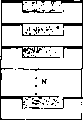
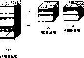
Figure 92 is the schematic diagram according to principle classification layer body of the present invention;
Figure 93 is the schematic diagram according to principle classification layer body of the present invention;
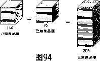
Figure 94 is the schematic diagram according to principle classification layer body of the present invention;
Figure 95 is the schematic diagram according to principle classification layer body of the present invention;
Figure 96 is the schematic diagram of getting the portion of putting according to principle of the present invention;
Figure 97 is the schematic diagram of getting the portion of putting according to principle of the present invention;
Figure 98 is the schematic diagram according to the selection adhesive means of principle of the present invention;
Figure 99 is the schematic diagram according to the treatment step of the mems device of principle of the present invention; And
Figure 100 is according to the schematic diagram of the treatment step of the mems device of principle of the present invention.
Embodiment
The present invention is relevant with the three-dimensional integrated circuit of formation.Before the specific formation that these three-dimensional integrated circuits are discussed, the substrate that is presented at first is discussed, as the unsettled U.S. Patent application No.09/950 of applicant in submission on December 9 calendar year 2001,909 " about film and manufacture method " in illustrated, this substrate is about a processing of selecting the multiple chip that the bonding multiple substrate allows wafer such as known, but more allow the chip layer of wafer to be easy to remove and preferably do not have machinery temper or additionally etching remove technology.But this chip layer then storehouse on another chip layer, as described below, or additionally, chip layer can be cut and storehouse to other chip.
With reference to Fig. 1, it shows that one selects bonding multiple substrate 100.Multilager base plate 100 comprises the layer 1 of the surperficial 1B with exposure, and surperficial 1A optionally is bonded to the surperficial 2A of layer 2.Further layer 2 comprises apparent surface 2B.Substantially, select for forming bonding multiple substrate 100, layer 1, layer 2 or layer 1 and 2 all be used to define weak bonded areas 5 and strong bonded areas 6 and after bonding, wherein weak bonded areas 5 has the condition that allows to handle a useful device or structure.
Usually, layer 1 and 2 is compatible.That is, layer 1 and 2 constitute compatible heat, machinery and/or crystallization property.In a particular embodiment, layer 1 and 2 is identical materials.Certainly, can use different materials, but preferably be compatible the selection.
One or more layer 1 is defined as substrate regions, wherein or to have one or more on it similarly be that microelectronic structure is formed.These zones can be any pattern of desiring, and will further describe among the application.Layer 1 selection area then can be processed the bonding degree is reduced to bonded areas 5 a little less than the most weak formation.Perhaps, layer 2 opposed area can be processed (handle together with layer 1, or the processing of substituted layer 1) bonding is reduced to minimum.Further alternative comprises, handles selectedly to form layer 1 and/or the layer 2 in the outer zone of structure, so similarly improves intensity in strong bonded areas 6.
After the processing of layer 1 and/or layer 2, layer body can be aligned and bond.By any proper method bonding.In addition, Ceng aligning can be machinery, optics or relevant combination.Should understand because the structure that on present stage layer 1, is not formed and can not considerably aiming at.Yet,, be to reduce a selected substrate regions variation indispensability to the brigadier if two layers 1 and 2 are treated.
Useful structure or device can be formed on zone 3 or on zone 3, partly or overlapping substantially weak bonded areas 5.Therefore, partly or the zone 4 of overlapping substantially strong bonded areas 6 usually therein or its top this structure not.After on the layer 1 of a user at multilager base plate 100 or layer 1 the inside is formed with device, can be disengaged bonding after the layer 1.Removing bonding can be by any such as the known technology that divests, and there is no need demixing technology that useful device is harmful to.Because useful device is not formed in the zone 4 usually or on the zone 4, these zones can suffer the releasing binder-treatment such as the ion implantation, be formed in the zone 3 or the structure on the zone 3 and can not injure.
In order to form weak bonded areas 5, surperficial 1A, 2A or both can processedly at weak bonded areas 5 places not bond in fact or weak bonding to form.Perhaps, weak bonded areas 5 can not handled, and mat makes the processed and strong bonding of inducting of strong bonded areas 6.Zone 4 partly or overlapping in fact strong bonded areas 6.For forming strong bonded areas 4, surperficial 1A, 2A or both can be processed at strong bonded areas 6 places.Perhaps, strong bonded areas 6 can not handled, and mat makes the processed and weak bonding of inducting of weak bonded areas 5.In addition, the treatment technology that two zones 5 and 6 can be different is handled, and wherein said treatment technology can be in nature or quantity ground difference.
After the combination of handling bonded areas 5 and strong bonded areas 6 a little less than one or two, layer 1 and 2 bonds together and forms the multilager base plate 100 of long-pending body on the entity.Therefore, after formation, multilager base plate 100 can be subjected to end user's adverse circumstances, for example, in order to form structure or device therein or on it, especially within the zone 3 of layer 1 or on.
Used word in the specification of the present invention " weak bonding " refers generally between vincible layer body or the cementation between the part layer body, for example, such as the releasing bonding technology that divests etc., other similarly be mechanicalness separation, heat, light, pressure or with the technology that comprises aforementioned releasing bonding technology combination at least.These are removed bonding technology layer 1 and layer 2 are caused minimum infringement, particularly at contiguous weak bonded areas 5 places.
Individual processing or both processing together for weak bonded areas 5 and strong bonded areas 6 can be in many ways.Be that about the important invention aspect of handling weak bonded areas 5 is easier to remove bonding (removing bonding according to further describing afterwards step) than strong bonded areas 6.This will be avoided the injury in zone 3 during removing bonding or it will be reduced to minimum, can comprise useful structure on the zone 3.In addition, comprise strong bonded areas 6 especially improves multilager base plate 100 therebetween in structure treatment mechanical integrity.Therefore, when the layer that removes therein or have useful structure on it 1 time, its subsequent treatment will be omitted or minimize.
Strong bonded areas to the volume efficiency of weak bonded areas (SB/WB) substantially greater than 1.According to the specific combination mode of strong bonded areas and weak bonded areas, and strong bonded areas to the opposed area size of weak bonded areas, the numerical value of SB/WB can be near infinitely great.That is, if strong bonded areas aspect the size and handle the time to keep the strength of machinery and heat stability enough big, the adhesion strength of weak bonded areas can level off to zero.Yet the SB/WB ratio can change tempestuously, is because the strength of strong bonding (in typical silicon and silicon derivative, for instance: silicon dioxide, wafer) can be from about 500 (mj/m
2) change to above 5000 (mj/m
2), disclose as known technology (for example, 104-118 page or leaf in " semiconductor wafer bonding technology " book is shown by Q.Y.Tong and U.Goesle, at this as a reference in 1999 publication by New York, United States John Wiley andSons publishing house).Yet, weak adhesion strength can in addition because of material, desirable useful structure (if known), the bonding selected for use with remove bonding technology, relative strong bonded areas than the configuration of the strong bonding on weak bonded areas, the wafer and weak bonding or pattern or the like change more tempestuously like that.For example, it is to be used in relieving layer body bonding that ion is implanted, and after the microvesicle that ion is implanted and/or ion implantation region is relative was evolved, useful weak bonded areas strength can be compared with the strength of strong bonded areas.Therefore, the strength ratio of SB/WB is looked closely selected releasing bonding technology and optional useful structure or the device selecting to be formed in the weak bonded areas usually greater than 1 or preferably greater than 2,5,10 even higher.
Look closely selected material for individual treated or two zones weak bonded areas of together handling 5 and the special processing pattern that strong bonded areas 6 is taked.In addition, the bonding technology of layer 1 and layer 2 is selected at least in part according to handling rule.In addition, releasing bonding afterwards can be according to structure kenel or the factor such as combination that comprises one of aforementioned factor at least such as treatment technology, adhesive method, material, useful structure kenel or existence.In certain embodiments, selected treatment combination, bonding and the bonding of releasing afterwards (that is, can be formed on useful structure in the zone 3 by an end user or as intermediary's member of a higher-order device) do not need to propagate with division to remove layer 1 or mechanical type attenuation from layer 2 and remove layer 2 and preferably save division and propagate and mechanical type attenuation dual mode.Therefore, diminish layer 2 according to the division propagation that disclosed of tradition or mechanical type attenuation, cause its in essence if without subsequent treatment then just as of no use, its bottom substrate seldom even is not repeated to use.
With reference to Fig. 2 and 3, wherein be positioned at the similar reference number of same zone contrast, but a kind of treatment technology comprises and utilizes the slurry that contains a solid-state module and a schematic diagram illustrating on surperficial 1A, 2A or 1A and the 2A.Solid-state module can be alumina, silica (SiO (x)), other hard metal or metal oxide or other bonding with layer 1 and layer 2 reduced to other minimum material.But schematic diagram illustrating can be ethene polymers (PVA) or other decomposable polymer that is fit to.Generally, slurry 8 is applied in surperficial 1A (Fig. 2), 2A (Fig. 3) or the 1A and the 2A of weak bonded areas 5.Next, layer 1 and/or layer 2 can be heated, preferably decomposing copolymer in inert environments.Therefore, infiltration structure (solid-state module that comprises slurry) remains on weak bonded areas 5, and in case bonding, layer 1 and layer 2 are non-caked in weak bonded areas 5.
With reference to Figure 4 and 5, another treatment technology can change according to the surface roughness of 6 of weak bonded areas 5 and strong bonded areas.Surface roughness can be in surperficial 1A (Fig. 4), surperficial 2A (Fig. 5) or surperficial 1A and upward adjustment of 2A.Substantially, weak bonded areas 5 can have the rough surface 7 (Figure 4 and 5) that is higher than strong bonded areas 6.For example, in semi-conducting material, weak bonded areas 5 can be had an appointment greater than a surface roughness of 0.5 nanometer (nm), and strong bonded areas 4 can have a lower surface roughness, is less than 0.5nm usually approximately.In another example, weak bonded areas 5 can be had an appointment greater than the surface roughness of 1nm, and strong bonded areas 4 can have a lower surface roughness, is less than about 1nm usually.Again in another example, weak bonded areas 5 can have approximately the surface roughness greater than 5nm, and strong bonded areas 4 can have a lower surface roughness, is less than 5nm usually approximately.Surface roughness can be with etching adjustment (for example, with KOH or HF settling mode) or deposition modification of program (for example, low-pressure chemical vapor deposition (LPCVD) or electricity slurry enhanced chemical vapor deposition (PECVD)).The bonding strength relevant with surface roughness is described in more fully, for example, the 148th (4) G225-G228 (2001) phase of electrochemical periodical, " the selectivity wafer bonding of control surface roughness " technology of Gui etc., in the application as a reference.
(wherein similar region is with reference to Reference numeral similar in the Figure 4 and 5) in the same manner, a porous zone 7 can be formed on weak bonded areas 5, and strong bonded areas 6 can keep not being subject to processing.Therefore, layer 1 the most faintly bonds with layer 2 at weak bonded areas 5 places owing to the permeability of weak bonded areas 5.Permeability can be in surperficial 1A (Fig. 4), surperficial 2A (Fig. 5) or surperficial 1A and upward adjustment of 2A.Substantially, weak bonded areas 5 has the permeability (Figure 4 and 5) that is higher than strong bonded areas 6 in porous zone 7.
Another treatment technology can be according to bonded areas a little less than the selective etch 5 (at surperficial 1A (Fig. 4), 2A (Fig. 5) or 1A and 2A), then impose the deposition (for example, but comprise that polymer is the decomposing material of base material) of a photoresistance or other carbonaceous material at this etching area.In case layer 1 and layer 2 bonding, preferably in the temperature that is enough to decompose carrier material, comprising the weak bonded areas 5 of a permeability carbonaceous material, make that 2 bonding in weak bonded areas 5 of layer 1 and layer are very weak compared to layer 1 and 2 bondings in strong bonded areas 6.Those skilled in the art can understand that according to circumstances the gas of selecting can not leak, dirty decomposition material or other besmirch that substrate layer 1 or 2 decomposes materials or any useful structure is formed on zone 3 or the decomposition material on zone 3.
Further treatment technology can use radiation to obtain strong bonded areas 6 and/or weak bonded areas 5.In this technology, layer 1 and/or layer 2 come radiation and obtain required strong bonding and/or weak bonding with neutron, ion, proton beam or the combination stated.For example, such as He
+, H
+, or other suitable ion or proton, electromagnetic energy or laser beam can be in strong bonded areas 6 radiation (at surperficial 1A (Figure 10), 2A (Figure 11) or 1A and 2A).Will be appreciated that this radiation method is with the different of ionic-implantation, it is less a lot of at dosage and/or implantation energy for layering usually.(for example, the dosage that is used for layering is according to the 1/100th to the 1/1000th magnitude)
With reference to Fig. 8 and 9, further treatment technology comprises the surface of the weak bonded areas 5 of etching.At this etching step, column 9 is defined in the weak bonded areas 5 on surperficial 1A (Fig. 8), 2A (Fig. 9) or 1A and the 2A.Optionally etching of column, stay column and define.The shape of column can be triangle cylindricality, pyramid, rectangle, hemispheric or other suitable shape.Perhaps, column can be in etched zone implanted or deposition.Owing to have only seldom bond regions allow the material bonding, in the overall strength of weak bonded areas 5 much smaller than bonding in strong bonded areas 6.
Another treatment technology is still arranged, and it comprises a dummy section 10 (Figure 12 and 13) about utilizing such as etching, mechanism or both (material on use is decided) formation in the weak bonded areas 5 of layer 1 (Figure 12), layer 2 (Figure 13).Thus, when ground floor 1 is bonded to the second layer 2, dummy section 10 will make bonding reduce to strength with respect to strong bonded areas 6 minimums, the releasing bonding after promoting.
Referring again to Fig. 2 and 3, another kind of again treatment technology comprises one or more metallic region 8 about the weak bonded areas 5 on surperficial 1A (Fig. 2), 2A (Fig. 3) or 1A and 2A.For example, comprise but the copper, gold, platinum or other any combination that do not limit or alloy can be located on the weak bonded areas 5 long-pending.In case layer 1 and layer 2 bonding, weak bonded areas 5 will faintly bond.Strong bonded areas can keep not being subject to processing (wherein this bonding strength difference provide about weak tack coat 5 and by force bond regions 6 necessary strong bondings to weak bonding ratio) or can processing aforementioned or that will narrate afterwards strengthen adhesion.
A kind of further treatment technology comprises the one or more enhancement adhesions 11 of use about the strong bonded areas 6 on surperficial 1A (Figure 10), 2A (Figure 11) or 1A and 2A.Suitable enhancement adhesion comprises, still is not limited to: TiO (x), metal oxide or other enhancement adhesion.Another is selectable, promotes adhesion and can be used for big supreme all surperficial 1A and/or 2A, and wherein a kind of metal material is placed between the 1A or 2A (deciding at the scene on promoting adhesion) on the surface of promoting adhesion and weak bonded areas 5.Therefore in a single day bond, metal material will be avoided the strong bonding in a weak bonded areas 5, and promote strong bonding at the enhancement adhesion of strong bonded areas 6.
Still having another kind of treatment technology to comprise provides drainage and/or hydrophilic region of variation.For example, hydrophilic zone is useful especially to strong bonded areas 6, because similarly be that the material of silicon can at room temperature cling naturally.The known bonding technology that utilizes drainage and hydrophily in room temperature and intensification, being disclosed in John Wiley and Sons publishing house publishes in 1999, shown in " semiconductor wafer bonding technology " book in the 49-135 page or leaf by Q.Y.Tong and U.Goesle, in the application as a reference.
Another treatment technology comprises the selectively spalling effect layer penetrated of the width of cloth of one or more quilts again.For example, one or more spalling effect layers can be placed on surperficial 1A and/or the 2A.Use the spalling effect layer just as adhesion in the absence of radiation.Penetrate down in case be exposed to the width of cloth of penetrating such as the ultraviolet light width of cloth in the weak bonded areas 5, adhesiveness is reduced to minimum.Useful structure can be formed on weak bonded areas 5 or weak bonded areas 5, and a follow-up ultraviolet light radiation step or other a releasing bonding technology can be used at strong bonded areas 6 separates layers 1 and layer 2.
With reference to Fig. 6 and 7, extra treatment technology comprises that implanting ions 12 (Fig. 6 and 7) makes in layer 1 (Fig. 6), layer 2 (Fig. 7) in the weak zone 3 or two layers 1 and 2 and promptly can form a plurality of microvesicles 13 once heat treatment.Therefore, bonded when layer 1 and layer 2, weak bonded areas 5 will bond to such an extent that lack than strong bonded areas 6, to promote the releasing adhesion step after the layer 1 of weak bonded areas 5 and layers 2.
Another kind of treatment technology comprises one only followed by the ion implantation step of an etching step.In this embodiment, this technology is implanted all haply surperficial 1B via ion and is carried out.Thereafter, optionally etching of weak bonded areas 5.This method with reference to people such as Simpson in solid-state file the 4th (3) G26-G27 of electrochemical " implantation of indium phosphide induct selective chemical etching " about selecting the description of the shortcoming that the infringement etching removes, herein as a reference.
Again another treatment technology as can be known, what selectively be placed on weak bonded areas 5 and/or strong bonded areas 6 has that the width of cloth is penetrated and/or one or more layers of reflection characteristic, can be basic according to narrow or wide wave-length coverage.For example, the one or more layer that selectively is placed on strong bonded areas 6 can be exposed to specific radiation wavelength under and the characteristic of adhesion arranged according to looking, so a layer bulk absorption width of cloth penetrate and strong bonded areas 6 places that bond layers 1 and 2.
Those skilled in the art can understand, are used any extra treatment technology and comprise at least wherein a kind of technology of aforementioned techniques of combination.Yet any key characteristic that adopts technology is to form the ability of one or more weak bonded areas and one or more strong bonded areas, makes SB/WB strength ratio greater than 1.
The geometry 6 of weak bonded areas 5 and strong bonded areas can be at the interface of 2 on layer 1 and layer according to comprising but the following factor that does not limit change: be formed on the useful structure kind on zone 3 or the zone 3, selected releasing bonding/bonding pattern, selected treatment technology, reach other factor.With reference to Figure 14-20, multilager base plate 100 can have (Figure 20) or the combination trellis and (Figure 19) of annular or the weak bonding and the strong bonded areas of any above-mentioned form combination that can be concentric (Figure 14,16 and 18), (Figure 15) that striated is arranged, radial (Figure 17), trellis.Certainly those skilled in the art can judge how to select any geometry for use.In addition, strong bonded areas can change the ratio of weak bonded areas.Generally speaking, ratio provides the cementation (that is, in strong bonded areas 6) of filling part and need not comprise whole sandwich construction 100, especially during structure treatment.Preferably, this ratio also makes the useful zone (that is weak bonded areas 5) of structure treatment reach maximum.
After one surface of weak in fact as the aforementioned bonded areas 5 and/or strong bonded areas 6 or two surperficial 1A and 2A were processed, layer 1 and 2 bonded together and forms a whole in fact multilager base plate 100. Layer 1 and 2 can be bonded in together by multiple technologies and/or physical phenomenon, comprise but be not limited to: merge altogether that gold, fusion, plating, vacuum, the Fan Dewa power of hearing, chemical adhesion, drainage, hydrophily, hydrogen bond, Coulomb force, capillary force, utmost point low coverage power or comprise the combining ability etc. of one of aforementioned bonding technology and/or physical phenomenon at least.Certainly those skilled in the art can understand bonding technology and/or physical phenomenon look closely employed one or more treatment technology, thereon or the useful structure kenel that forms therein, expection remove adhesive method or other factor and select to use it.
Another can select mode for use, and an oxide skin(coating) of burying underground can be formed on the basal surface of device layer.Oxide skin(coating) can be formed into monolith substrate before the selectivity bonding early than device layer.In addition, oxide skin(coating) can oxygen be implanted to a degree of depth that needs buried oxide layer.
On multilager base plate, form the monoxide layer various technology is arranged.First kind of technology that forms the silicon dioxide layer bury underground in silicon substrate is by grinding in being higher than under 1300 ℃ the temperature behind the oxygen of implanting high concentration.Implant through ion, can form the thickness of the silicon dioxide layer of being desired of burying underground.
Another selected for use the technology that forms a buried oxide layer is included on the surface of multilager base plate and forms a thin silica membrane, then via silica membrane bonding substrate to one second silicon substrate.Utilize known mechanical is ground and polishing has a desired thickness silicon layer on then by the buried oxide silicon layer.Silicon oxide layer on the multilager base plate is with oxidized surface continuously, then this oxidized surface that forms in regular turn of etching obtains the formation of needed thickness.
The another kind of technology that forms an oxide skin(coating) of burying underground, it is by the thin silicon oxide layer of oxidation on one first multilager base plate, then implant the H+ ion in first multilager base plate to be formed on a cavity plane below the thin silicon oxide layer.Thereafter, see through thin silicon oxide layer, first body is glued to one second multilager base plate, and whole then assembly is limited by heat effect and gets off the cavity plane is transformed into a cleaved plane.So can reply a spendable SOI substrate.
For example, active device can be formed on multilayer SOI wafer or the substrate.These active devices are formed in the monocrystalline silicon active layer on the buried oxide film of SOI substrate.The thickness of silicon active layer is looked closely the purpose that wherein forms active device and is decided.If the SOI element is Cmos (CMOS) element of operating under high speed and low power consumption, active layer thickness is approximately 50nm to 100nm.If the SOI element is the high breakdown voltage element, active layer thickness can be several microns.A protectiveness diode is a kind of example of active device.One protectiveness diode is supplied with the semiconductor element of semiconductor equipment, makes its leading overcurrent connect pin to a substrate and to the outside of semiconductor device from one, protects the internal circuit of semiconductor equipment by this.
Those skilled in the art can understand quite that other active device can selectivity mixes up and shields monocrystalline silicon substrate or the SOI substrate is made.Active device can comprise but not be restricted to: bipolar junction transistor, metal oxide semiconductor transistor, field-effect transistor, diode, insulation lock bipolar transistor, and like that.
The active device that can make on multilager base plate is a mems device in addition.Usually, but mems device has comprised electrode and with respect to making the exciting element that electrode is joined cloth on the substrate.But exciting element shifts control from electrode and provides electrical control to machine construction.For making a kind of technology of mems device, it adopts the type manufacturing technology of deducting to be because it relates to from a single substrate layer eating away material and forms the MEMS structure by the whole micromachined substrate that utilizes dark etch processes.Substrate layer can be 10 micron orders and is relatively thick, and the measure of precision of the method makes the micromachined of different structure in the substrate, such as outstanding purlin, bridge joint, canal, cavity, nozzle and film.
Another technology that can make mems device on multilager base plate is the micromachining technology by the surface.It is regarded as a kind of addition method is because the space layer of structure sheaf at interval and sacrifice is to realize that with " up building " machinery of mems structure and electrical characteristics make.Polysilicon (polysilicon) is the structural material that the most generally uses, and silica glass is the consumptive material that the most generally uses.In traditional micromachined program, it is right that these layers form the polysilicon/oxide of isolating with one deck silicon nitride on the silicon substrate.These layers use optical lithography to form complicated structure, similarly are motor, gear, mirror and wave beam.When layer is established, cuts peroxide layer and fill up and locate structure sheaf or bottom structure layer with polysilicon.
The one or more selections zone 3 of layer 1 or on form one or more structures after, layer 1 can several different methods be removed bonding.As can be known because structure is formed on partly or covers substantially in the zone 4 of weak bonded areas 5 or on the zone 4, the releasing bonding of layer 1 can replace with reduce or eliminate such as the injury to structure in the relevant tradition of structural disadvantages or deformation.
Removing bonding can finish by multiple technique known.Generally speaking, whether remove existence that bonding technology looks closely treatment technology, bonding technology, material, kenel or possible constructions at least in part, or other the factor.
With reference to Figure 21-32, remove bonding technology and can form microvesicle according to the reference depth that is implanted in of ion or proton, generally the thickness with layer 1 equates.Ion or proton can be derived from oxygen, hydrogen, helium or other particles 14.Can or comprise foregoing a kind of combination at least by strong electromagnetic radiation, heat, light (for example, infrared light or ultraviolet ray), pressure after implanted, make particle or ion form microvesicle 15 and finally enlarge and make layer 1 and 2 layering.Also can follow a mechanical isolation step (Figure 23,26,29,32) after implantation and optionally heating, light and/or the pressure treatment, for example, eliminate a combination of direction (as Figure 23,26,29,32 interrupt lines indicated) or above-mentioned direction with layer 1 direction vertical, with layer 1 and 2 direction, one that is an angle with one with 2.For example, in U.S. Patent No. 6,027,988 cases of Cheung etc. " making film " by name, further carefully state the ionic-implantation of separation of thin layers from electricity slurry dipping ion implantation method that monolith substrate separates, in the application as a reference.
With reference to Figure 21-23 and Figure 24-26, optionally implanting at the interface between layer 1 and layer 2 forms microvesicle 17 in strong bonded areas 6 especially especially.In this way, the implantation of particle 16 in zone 3 (therein or have on it one or more available structures) is reduced to minimum, so may reduce repairable possibility or aplastic infringement takes place useful structure in the zone 3.Optionally implant the ion beam that to select and scan strong bonded areas 4 (Figure 24-26) or shielding area 3 (Figure 21-23).The ion beam of selecting scans the mechanical treatment of reference structure 100 and/or is used to indicate with the implanted ion or the device of particle.Those skilled in the art as can be known, various device and technology can be used to carry out selectivity and scan, and include, but are not limited to focus on ion beam and electromagnetic beam.In addition, various shielding materials and technology also are widely known by the people.
With reference to Figure 27-29, implantation can be passed whole surperficial 1B or 2B in fact.Look closely target and embedded material and be implanted in the suitable level and the desirable degree of depth.Therefore, layer 2 is more than layer 1 thick many place, and it is unpractiaca implanting and passing surperficial 2B; Yet if layer 2 is implanted (for example, with feasible implantation energy) with suitable thickness, the implantation of passing surperficial 2B is desirable.This will reduce repairable possibility and be removed or reduce the aplastic infringement that may take place useful structure in zone 3.
In one embodiment, and with reference to Figure 30-32 and Figure 18, strong bonded areas 6 forms in the outer rim at layer 1 and 2 interface of layer.Therefore, for example, remove tack coats 1 from layer 2, implantable ion 18 is by the microvesicle of formation at the interface of zone 4 on 2 on layer 1 and layer.Preferably, use selectivity to scan, wherein this structure 100 can be rotated (arrow 20 directions), and scanning apparatus 21 can be rotated (arrow 22) or a kind of combination wherein.In this embodiment, a more progressive advantage is to give the end user, and available configuration aspects provides very big flexibility ratio on it selecting.The size (that is width) of strong bonded areas 6 is suitable for keeping the machinery of multilager base plate 100 and the integrality of heat.Preferably, the size of strong bonded areas 6 is reduced to minimum, makes weak bonded areas 5 be used for the zone maximization of structure treatment.For example, strong bonded areas 6 was about one micron at one or eight o'clock on the wafer.
In addition, from layer 2 remove bonding layer 1 can be begun to form an etching of passing strong bonded areas 6 such as such conventional method picture (parallel surfaces) method of etching by other.In an embodiment like this, treatment technology is specific compatible, and for example, wherein strong bonded areas 6 and has oxide skin(coating) far above the etching selectivity of integral material (that is, layer 1 and layer 2) when being subject to processing together.Weak bonded areas 5 preferably need not be etched with at weak bonded areas 5 places from layer 2 and remove tack coat 1, because selectivity is handled or do not handled, has avoided layer 1 is bonded to the step of layer 2.
Perhaps, fracture propagation can be used to begin to remove tack coat 1 from layer 2.Again, removing bonding preferably only needs at strong bonded areas 6 places, is because of limited in the bonding of weak bonded areas 5.And as known to known, removing bonding can etching (vertical surface) beginning and preferably be limited in the scene (that is, partly or overlapping substantially strong bonded areas 6) in zone 4.
In another embodiment, and with reference to Figure 85, the method for its demonstration one releasing bonding.Comprise a multilager base plate 100 is provided; In WB zone 5, handle one or more useful structures (not showing); Etch away in SB zone 6, preferably with an angle that diminishes gradually (for example, 45 degree); Making device layer preferably only be subjected to low energy ion in etched SB zone 6 implants; And prune in the WB zone or remove the device layer part simply.Note, when two device layers at the WB layer are moved as shown, can understand this and can be used to promote allaying of device layer segment.The physical property ground, edge that the WB zone diminishes gradually promotes to move.Valuably, can utilize far below permeating the ion implantation energy of the required implantation energy of device layer thickness originally.
Layer 1 can be the same or different materials with layer 2, and material can including, but not limited to: plastics are (for example, polymerization carbon), metal, semiconductor, insulator, monocrystal, amorphous, noncrystal, biological (for example, DNA film) or comprise the combination of one of previous materials at least.For example, the material of particular type comprises that silicon (for example, monocrystalline, polycrystalline, amorphous, silicon polymer and derivative such as Si3N4, SiC, SiO2), material, IIB material, VIA material, sapphire, quartz (crystal or glass), diamond, silica and/or the silicate-based material of GaAs, InP, CdSe, CdTe, SiGe, GaAsP, GaN, SiC, GaAlAs, InAs, AlGaSb, InGaAs, ZnS, AlN, tin, other IIIA-VA, or any combination of one of flooring before comprising at least.Certainly, the processing of other material type can be benefited from method described herein provides desirable multilager base plate 100 to form.Especially herein the method for Miao Shuing is to be specially adapted to reach with semi-conducting material (for example, silicon) conduct layer 2 as layer with semi-conducting material (for example, silicon), and other combination comprises but is not limited in: semiconductor (layer 1) or glass (layer 2); Semiconductor (layer 1) on sapphire (layer 2), the semiconductor (layer 1) on the silicon carbide (layer 2); GaN (layer 1) on sapphire (layer 2); GaN (layer 1) on glass (layer 2); GaN (layer 1) on silicon carbide (layer 2); Plastics (layer 1) on plastics (layer 2), its middle level 1 and layer 2 can be identical or different plastics; And at the plastics (layer 1) of (layer 2) on glass.
A kind of considerable advantage of the method and the multilager base plate that produces or the film of deriving from multilager base plate is to be formed on zone 3 or on zone 3, partly or overlapping substantially weak bonded areas 5.When layer 1 by when layer 2 removes, will remove on the entity the injury of useful structure or minimizing of making.Remove adhesion step and need to immerse (for example, implanting), the application of force or other releasing tack coat 1 and 2 essential technology usually by ion.Because in certain embodiments, zone 3 or in the zone structure on 3 does not need regional immersion, the application of force, maybe may cause not necessarily other program step of repairable structural damage, layer 1 and can be removed and maintenance process after not needing from its structure of deriving.Usually partly or substantially be overlapped on the zone 4 of strong bonded areas 6 and do not have structure, so these zones 4 can be subjected in immersion or the strength of structure not being had wound.
The material that a kind of advantage of this method is to constitute layer 2 is can be repeated to use and callable.For example, can use a single wafer with any known method derived layer 1.The layer 1 of deriving can selectively bond thereon according to describe remaining part (layer 2).When film was disengaged bonding, repeating step used the remaining part of layer 2 to obtain film conduct one deck 1 down.The method can constantly repeat before the film that no longer can carry out the remaining part derived layer 1 that maybe can't re-use layer 2.
After so in detail the generation type of a selectivity bonding multiple substrate being described in detail, after this will describing and utilize selectivity bonding multiple substrate to form the three dimensions integrated circuit.
With reference to Figure 80, wherein show from the 1st ... the N wafer stack reaches the therefrom isogonism schematic diagram of a crystal grain of cutting.For making clear illustrate coordinate and definition.The interlayer that one crystal grain and wafer stack have top surface and basal surface usually and extend to x and y coordinate direction, as the in-plane of indication.Note any direction that in-plane is included in the surface or extends on interlayer.Some layers body be storehouse on the z direction, is commonly referred to as herein vertically or in three-dimensional.
Behind a crystal grain cutting step, a crystal grain still has four edge surfaces that extend usually in the z direction except the surface of interlayer and top and bottom.
Referring now to Figure 33, have selectivity bonding substrate 100, it has as aforesaid strong bonded areas 3 and weak bonded areas 4.Though the strong bond pattern among the demonstration embodiment approximately as shown in figure 18, can understand strong bonded areas 3 and the weak bonded areas 4 that can utilize any pattern, wherein a circuit or other useful device form in weak bonded areas according to aforementioned.
Especially, the present invention can provide the U.S. Patent No. 6,355,501 than IBM to have more advantage, is that the present invention has many additional functions and the usefulness enhancing reduces continuous treatment step quantity simultaneously.
As example, show a zone with a dashed circle, and the other selection example in this zone will be explained the formation that is suitable at the circuit region of three dimensions storehouse with various decomposing schematic representation.
With reference to Figure 34, an example of display circuit part, it has suitable is the long-pending chip edge interconnect architecture of establishing of three dimensions.The edge interconnect architecture of thinner portion can be with reference in all U.S. Patent No.s 5,786,629 and 6,355,976 of Faris, both in the application as a reference.
A circuit part C is at an insulating regions 1 that is formed on the device layer of selecting the tack coat substrate.Can be electricity or a conductor W of optics can begin and extend to the circuit package border land and be formed from circuit part, be represented by dotted lines.Conductor W can extend on any direction in the x-y plane usually.Overall region during circuit part and conductor are handled as machinery and support heat.
Should recognize when only showing a plain conductor (before this and all afterwards embodiment), a plurality of conductors can be provided and generally link at upwardly extending each circuit part of any side on x-y plane.These conductors can be with the address of self each circuit part of encoding; Acceptance is from the address information of external address bus; Carry data and power each circuit part; Reception is from the data of circuit part (internal memory); Or other desired function.When using composite conductor, these conductors can be independently or are unnecessary.
In one embodiment, when wherein forming some independent conductors, known in the manufacture of semiconductor, the overlapping region is insulated especially.
Circuit part can be the same or different, and can various transistor and diode form.These devices comprise (in the same vertical integrated circuit the inside) the same or different microprocessor (electricity or optics) (bipolar circuit, cmos circuit or any other treatment circuit), the main memory circuit part receives and/or transmission circuit function or like that such as single device mnemon, DRAM, SRAM, animation soft, signal.Therefore, can this method form various product.Long-pending body formula product can receive and/or the transmission circuit function at multiple online processor and internal memory or processor, the internal memory signal of comprising with wireless device.(on the z direction) is long-pending by vertically establishes, and the chip improved treatment speed of very dense or stored storage reach the coefficient (N represents long-pending total number of plies of establishing, and can be one digit number, double figures even three-figure amount) of N.
With reference to Figure 35, get the portion of putting for one and be used for assisting to remove device layer.As above-mentioned, strong bonded areas is normally subject to and promotes to remove under the step of bonding, and for example, ion is implanted.Device layer thereby can be removed (for example, about Figure 23,26,29 and 32) as previously mentioned easily and need traditional tempering or other etched step.Because circuit part and conductor form in weak bonded areas, they usually can be not undermined during this removes step.In a preferred embodiment, the employed portion of putting of getting described in the PCT patent application PT/US/02/31348 " handling the Apparatus and method for and the relative manufacturing process of frangible object " by name of on October 2nd, 2002 application, in the application as a reference.
Device layer with a plurality of circuit parts and edge extension conductor aligns and storehouse as shown in figure 36, in further description herein.Layer body is aligned and storehouse vertically amasss the body storehouse so that a plurality of circuit part forms one.It is required and circuit part each layer can be identical or different to look vertical integrated device.
In a preferred embodiment, N layer body is by storehouse, and all afterwards N layers bond in an one step.For example, can finish by using ultraviolet ray or the heat treatment adhesion between layer body.Note, because interconnected position makes circuit part itself touch adhesion in certain embodiments and may not can be harmful at the edge of each chip.Though be not essential, can reduce treatment step and ultimate cost.
Referring now to Figure 37, each storehouse of circuit part cuts according to known technology.Can not provide edge-smoothing and be under the situation on plane at cutting step, the wiring edge can be polished so that each circuit part touches conductor.
Figure 38 shows the edge of a plurality of circuit parts with conductor W interconnected (electricity or optics).Can known method assign to finish to be electrically connected each circuit part by the film of shielding and etched conductors material deposition.Other interconnected method is at aforesaid U.S. Patent No.5, described in more detail in 786,629 and 6,355,976.
Noticeable focus on the edge interconnected can act on vertical long-pending establish chip and handle during and in the final products (the vertical long-pending chip of establishing).The interconnected usefulness that can be used as diagnosis in edge during the processing.So can during a plurality of circuit parts interconnected, keep away the circuit part that hair loss is given birth to fault.Perhaps, the circuit part that breaks down can be repaired.Another alternative embodiment again, the circuit part of a N layer stack can be removed the circuit part that breaks down by reduction (that is, flatly along the circuit part plane), and the following storehouse N of N layer more than two layers is provided.Use two or more storehouse and each storehouse has the circuit part's layering that is less than the N layer during some is used, replace and give up N layer stack, can increase the integral production amount of known non-defective unit crystal grain (KGD) tempestuously with one or more circuit parts that break down.
After this with reference to Figure 38, in another alternate embodiments, a vertical long-pending edge interconnect stack of establishing can provide vertical long-pending the establishing of a kind of of the present invention second vertical IC.As shown in Figure 38, long-pending body edge storehouse is interconnected to form a wiring storehouse around its vertical axis rotation effectively.Be bonded to the second vertical IC by the long-pending body edge storehouse that will rotate, can realize the adaptability that connects up.For example, the long-pending body edge interconnect stack of rotation can provide adaptive above the wiring of one deck in the scale of a level.For example, this to need multiaddress cauing line and control circuit to one be useful with the required control circuit of the mass data storing chip of addressing and control.
In a further embodiment, the edge is interconnected to can be used as a large amount of storage addressing (MSA) 6,355,976 descriptions of U.S. Patent No. as described above.
With reference to Figure 39, another example of display circuit part, it has the path interconnect architecture that is adapted to the long-pending body of three dimensions.One circuit part C is selecting bonding to divide the insulating regions I the inside of the device layer of laminar substrate to be formed.Can be conductor W electric or optics can operate and begin from circuit part and extend to the bottom of multilager base plate device layer.Each circuit package is represented by dotted lines.Overall region during the processing of circuit part and conductor as machinery with the support of heat.Conductor W (can be associated with each circuit as described above) may extend into the bottom lateral margin of device layer, perhaps can extend in the direction of device layer bottom lateral margin, polishing step is performed so that vertical interconnect touches conductor by this.
Then get the portion of putting and to be used to remove device layer for one, usually as shown in figure 35.
The device layered stacks has a plurality of circuit parts, then sees through conductor as shown in figure 40 and is aligned and storehouse, and next further description is arranged.Layer body is aligned and storehouse vertically amasss the body storehouse so that a plurality of circuit part forms one.It is required and circuit part each layer can be identical or different to look vertical integrated device.
In a preferred embodiment, N layer is by storehouse, and follow-up all N layers bond in an one step.For example, this can realize to pass through to use ultraviolet ray or the adhesion of heat treatment between layer body.And in order to avoid the contact problems between the perpendicular layers body, get in the portion of putting and should avoid adhesion.
Just like what show among Figure 41, each circuit part storehouse cuts according to known technology.
With reference to Figure 42, another example of its display circuit part, its have comply with three dimensions long-pending establish to blend together the edge interconnected interconnected with path.A circuit part C is selecting bonding to divide the insulating regions I the inside of laminar substrate device layer to be formed.Can be conductor W electric or optics
tCan operate and begin from circuit part and extend to the bottom of multilager base plate device layer.Apprehensiblely be W
tAlso be available as the coupler of a machinery, for example, a mems device.Another conductor W
eCan be from begin to extend to the edge of circuit package at circuit part, shown in dotted line.Overall region during the processing of circuit part and conductor as machinery with the support of heat.Conductor W
t(can be associated with each circuit as described above) may extend into the bottom lateral margin of device layer, perhaps can extend in the direction of device layer bottom lateral margin, polishing step is performed so that vertical interconnect touches conductor by this.Apprehensible, conductor W
tAnd W
eCan be made on along the precalculated position of wafer so that the edge extends conductor can make Anywhere along Waffer edge.
Then get the portion of putting and to be utilized to remove device layer for one, usually as shown in figure 35.Have a plurality of circuit parts and align as shown in figure 43 and storehouse afterwards, and further describe herein with the device layer that the edge extends conductor.Layer body is aligned and storehouse vertically amasss the body storehouse so that a plurality of circuit part forms one.It is required and circuit part each layer can be identical or different to look vertical integrated device.
In a preferred embodiment, N layer is by storehouse and all thereafter N layers bond in an one step.This can be by for example using, and ultraviolet ray or heat treatment adhesion are realized.
Referring now to Figure 44, each circuit part storehouse cuts according to known technology.Under the unsmooth nonplanar edge situation that in cutting step, causes, can polish the wiring edge so that each circuit part touches conductor W
e
Figure 45 shows a whole interconnected aspect, and a plurality of circuit parts are interconnected with conductor W ' (electricity or optics) edge.Can known method assign to finish to be electrically connected each circuit part by the film of shielding and etched conductors material deposition.Other interconnected method is at aforesaid U.S. Patent No.5, described in more detail in 786,629 and 6,355,976.
Note, when edge channel interconnected both when all being used, can utilize same type or two types to come the interconnection circuit part.Different interconnected can be unnecessary or independently.Perhaps, the interconnected purpose that can be used as diagnosis in edge is as aforementioned.In a more progressive alternate embodiment, the interconnected of two types can be used to provide unnecessary, reduces vertical long-pending body chip by this and starts the interconnected possibility that breaks down between the chip part.
For forming via conductor (shown in Figure 39 and 42), each via conductor of every chip part can at first be formed (for example, filling up this hole by hole of etching with conductive of material), so circuit part is formed on the conductor top.
In addition, with reference to Figure 46, circuit part C can at first be formed on first on device layer or at device layer, and via conductor W extends to the top of device layer from the top of circuit part.Zone above the circuit part can be processed with provide conductor W and insulating material I (with this insulator identical materials to reach optimum Match).
Referring now to Figure 47, identical structure among Figure 46 showed the vertical interconnected characteristic of circuit part of other selectable enhancing before wherein similar Reference numeral was represented among the figure.Usually has conductor Wb on the top of each circuit part.Conductor Wb is as optimizing from the via conductor Wt on the stack layer body.Conductor can comprise solid-state material so that effectively provide contact between layer body from the contact of a storehouse.Perhaps, conductor Wb can comprise solder bump, so that the conductor that adjoins can be by adding thermal.Perhaps another kind of again available means, conductor Wb can comprise the electrical ties of adjoining between circuit part.Again, conductor Wb can be the pure optics connection that comprises optical waveguide.The combination of conductor can realize at all N layers storehouse when each layer of storehouse or preferably afterwards, and the conductor connection injury that many reflux operations are caused minimizes, as 6,355,501 descriptions of U.S. Patent No. of above-mentioned IBM.
Form the method (as shown in Figure 39 and 42) of via conductor and the Figure 48-50 that addresses now at another, the device layer of separation can form circuit part's layering.Shown with reference to Figure 48, the device layer with circuit part, each device layer have the conductor Wb that contacts with other device layer with path contact.Conductor Wb can have solder bump or permanent solid conductor.Notice that second conductor Wb part can provide the conduction from the via conductor Wt of storehouse upper strata body as the aforementioned content of reference Figure 47.Figure 49 shows that has the device layer that path connects Wt.Layer body can be as shown in figure 50 with storehouse, bonding, and provide a sub-storehouse that comprises circuit part's layering and conductor layer in conjunction with electrical contact device.
Referring now to Figure 51, wherein show another selectable circuit part layering.An oxide skin(coating) of burying underground (BOx) is formed in the general device layer at the interface between monolith substrate and device layer.The oxide skin(coating) that this buries underground in the known technology can various method form, and similarly is O
+Ionic-implantation.In addition, the oxide skin(coating) of burying underground can be after device layer optionally be bonded to monolith substrate or before be formed.
The oxide skin(coating) of burying underground in device layer by the embodiment that forms before optionally being bonded to monolith substrate in, a SiOx layer can be formed on device surface before selectivity is bonded to monolith substrate.So device layer optionally is bonded to monolith substrate.Notice that it can be satisfactorily handles oxide skin(coating) earlier and strengthen bonding before bonding.
The oxide skin(coating) of burying underground in device layer by the embodiment that forms after optionally being bonded to monolith substrate in, device layer can be by for example, oxygen is implanted to form oxide skin(coating) at the depth desired place, that is, and with the interface between monolith substrate and device layer.It is gratifying that strong bonded areas oxidation is avoided in the zone that the shielding device layer desires to bond by force regionally.
After the oxide skin(coating) of burying underground formed, circuit part C was adjacent to the buried oxide formation in the weak bonded areas on the device layer.Conductor W2 forms contacting of (for example, deposition) and circuit part with electric or optics, and conductor W1 be with electricity or the contacting of optics with conductor W2.Notice that conductor W1 and W2 can form in a step or in a plurality of steps.Simultaneously, when conductor W1 and W2 were shown as T shape, that these conductors (or the plain conductor of an identical work with) can be was L shaped, rectangle or any other suitable shape.
After monolith substrate (as above-mentioned) removed, the oxide skin(coating) of burying underground was exposed out at device layer.Shown in Figure 52, an oxide skin(coating) zone of burying underground can etchedly be left, and via conductor W3 forms therein.Conductor W3 is used as on the storehouse device layer and adjoins the interconnected of conductor W1.
Though described method on some aspect in the U.S. Patent No. 6,335,501 of IBM for the announcement of chip-scale, but method of the present invention has multiple advantage.In above-mentioned preceding case, monolith substrate removes only by tempering and etching, eliminate or other easier moving method yet have on the method for the present invention, the circuit part that it forms based on weak bonded areas and the existence of strong bonded areas are to be supported to the layer body of whole support substrate, as mentioned above.In addition, method of the present invention can obtain on a wafer-scale.Satisfied productivity ratio can by layer body examination examination, and a lot of N layers of later use and the storehouse that is less than the N layer cause, according to top description.
Referring now to Figure 53, another selectable circuit part layering link with it conductor embodiment as shown.An oxide skin(coating) of burying underground (BOx) is formed in the device layer at the interface between monolith substrate and device layer.A conductor forms on the regional BOx at circuit part and forms.Circuit region is formed, and conductor W2 and W3 (or a whole conductor) are formed on the top of circuit part.Notice that conductor W1 (or conductor part) protrudes abdominal section with the edge that diminishes gradually and one--this is used as the mechanical integrity that promotes to aim at and improve conductor among other material.
Referring now to Figure 54, after device layer was removed from monolith substrate (according to above-mentioned, can utilize to eliminate), the oxide skin(coating) of burying underground then was exposed and forms the W3 zone.Preferably, these zones are consistent with shape and the size of conductor that diminishes gradually or conductor part W1.
Be shown in the W3 zone as Figure 55, a scolder embolism is provided as and forms conductor W3 at last.This conductor W3 as with an adjacent storehouse on the conductor W1 interconnection layer of device layer, shown in Figure 56.
In the time of layer body storehouse, in one embodiment, the layer body of storehouse can be refluxed conduct will be by the layer body of storehouse.In a preferred embodiment, after N body formation layer by layer, whole storehouse is limited by reflow treatment.Also have another embodiment, storehouse can reflux in the part section.
The shape of the conductor W1 of separating layer and W3 and angle further assist mechanically to align by the layer body of storehouse as can be known.
Referring now to Figure 64, show one embodiment of the device layer that further forms a three dimensions circuit or memory devices.An oxide skin(coating) of burying underground (BOx) is formed in the device layer at monolith substrate and device layer interface usually.This oxide skin(coating) of burying underground can be formed by various different known methods.In addition, the oxide skin(coating) of burying underground can form before or after device layer optionally bonds monolith substrate.Notice that the device layer with BOx can be as the above-mentioned SOI wafer layer that removes with derive " unprocessed ", this layer can be supplied with a consumer or store and give processing afterwards.
Formed among the embodiment of the oxide skin(coating) of burying underground before device layer selectively bonds monolith substrate, a SiO2 layer can be formed at the monolith substrate surface before device layer selectively bonds monolith substrate.Device layer then optionally is bonded to monolith substrate.Notice that it can be satisfactorily handles oxide skin(coating) earlier and strengthen bonding or shielding device layer and desire the zone of strong bonding and avoid strong bonded areas oxidation regionally before bonding.
Form after device layer selectively bonds monolith substrate among the embodiment of the oxide skin(coating) bury underground, device layer can be for example, and oxygen is implanted in the required degree of depth and forms oxide skin(coating), that is, between monolith substrate and device layer at the interface.
After the oxide skin(coating) of burying underground formed, circuit part C was adjacent to the buried oxide formation in the weak bonded areas on the device layer.One or more conductor W form contacting of (for example, deposition) and circuit part with electric or optics, and may extend into any spatial edge of chip, as above-mentioned.
Be described in device layer after monolith substrate (as mentioned above) removes at this, the oxide skin(coating) of burying underground is exposed.The BOx layer can be used as a penetrating insulator layer, and can be in order to cover one deck body as the shielding to other layers when the layer body storehouse.Again, the BOx layer provides a ready insulator partly to use or be provided at noise shielding between conductor in buffer circuit.In addition, can etch a hole in the BOx layer, with reference to Figure 52 and 54 descriptions, reach the above-mentioned IBM U.S. Patent No. of mentioning 6,355,501 as the front.
With reference to Figure 57, the example of another circuit part is shown as has the chip edge interconnect architecture that is adapted to the long-pending body of three dimensions.Further the chip edge interconnect architecture is carefully stated to be found in and is sought in all United States Patent (USP)s of aforementioned Faris the 5th, 786,629 and 6,355,976.In this embodiment, a circuit part C forms in an insulating regions I the inside of the device layer of selecting bonding layered stacks substrate.Herein, conductor is formed on the multiple edge of each circuit part, represents with WL, WR and WR/WL.Yet, notice that conductor can also or optionally to all the winds extend to a layer body (for example, arriving four main edges of circuit part) to vertical line.
The device layer body has a plurality of circuit parts, so and multiple edge extends conductor according to alignment and storehouse shown in Figure 58.Layer body is aligned and storehouse vertically amasss the body storehouse so that a plurality of circuit part forms one.Look vertical the required circuit part of integrated device and each layer body can be identical or inequality.Again, be presented on each layer, estimate that generally some layer can have one, two, three or four edge interconnected though the edge is interconnected.General further estimate some layer can have unique pass through interconnected.Estimate further that again some layer can have one, two, three or four interconnected and one or more path in edge interconnected.
In a preferred embodiment, N layer is by storehouse, and all continuous N layers are to bond in an one step.This can utilize, and for example, ultraviolet ray or heat are come due to the adhesion between the processing layer body.Note, owing to generally be interconnected at the edge of each chip,, and can reduce treatment step and spend at last though the exposed circuits part itself touches that adhesion is nonessential can not to be harmful to yet in certain embodiments.
Referring now to Figure 59, each storehouse of circuit part cuts according to known technology.Under the edge situation of cutting the plane that can't provide level and smooth, the wiring edge can polishedly make circuit part touch each conductor.
With reference to showing among Figure 60 that a plurality of circuit parts edge and conductor W ' R and W ' L (electricity or optics) are interconnected, though generally estimate to have some or all of layers and have the edge of vertical paper interconnected (sensing and/or from paper).The method that can use the deposit film of known shielding and etched conductors material is electrically connected each circuit part conductor.Other mutual contact mode U.S. Patent No. 5,786,629 and 6,355,976 is as described above described in more detail.
Importantly, the edge is interconnected can reach effect in the final products (the vertical long-pending chip of establishing) during vertical long-pending body chip is handled.When handling, the interconnected effect that can be used as diagnosis in edge.Still various selection can be arranged.For example, interconnected the functional of diagnosis and other electric weight, data, memory access or other individual circuits part that be available as in one or more edges.The one or more interconnected of edge can be remaining, with the improvement device yield.Edge interconnected access circuit independently part zones of different is functional with what increase.A large amount of storage addressing functions also are feasible, provide interconnected according to client's needs in high density storage equipment.
Figure 61 is not for demonstrating the vertical long-pending isometric view of establishing chip of interconnected W '.Figure 62 is a possible vertical long-pending chip of establishing that shows interconnected W.Attention can have the combination of the interconnected W ' of various differences, looks closely needed functional.(for example utilize one, two, three or four edges and selective channel conductor, stack bottom or top layer), more make interconnected section strength multiplication (interconnected) and high flow capacity interconnected compared to a path, use reaches six faces (or more, if more polyhedral words) of the long-pending body portion of three-dimensional perpendicular.Multi-conductor can extend from each edge in addition, for example, and edge that links with the different piece of the circuit part of certain layer or remaining edge.
With reference to another example of Figure 63 display circuit part, it has complies with the long-pending chip edge interconnect architecture of establishing of three dimensions.In this embodiment, a circuit part C is selecting bonding to divide the insulating regions I the inside of laminar substrate device layer to be formed.The device layer surface of one or more conductors on circuit part forms with passing through.Generally, provide to extend and pass through chip part (right and left shown in Figure 63) partly, to increase the productivity ratio under the fault state that a vertical side of amassing the body chip is damaged or can't be interconnected as remaining.Notice that as described above, multi-conductor can pass the zones of different of wafer with the access circuit part.
Referring now to Figure 81 and 82, compare the patent No.6 of a present invention (Figure 81) and an above-mentioned IBM, 355,501 methods that disclosed (Figure 82).Figure 82 (IBM) is presented at a SOI device on the BOx layer.Metallization only is provided on the Z direction, that is, pass through with bottom vertical on the top of SOI device and to be connected.Especially, provide the edge interconnected, provide and increased device efficiency, reduce whole treatment steps, also allow and strengthen and simplify interconnected function such as diagnostic with meaning shown in the present and narration.
In certain embodiments, can be gratifying by increasing size (contact area), the coefficient of conductivity (minimizing resistance coefficient) or both, and strengthen the interconnected of wafer-scale described herein or chip-scale storehouse device.
Referring now to Figure 83, show an embodiment who improves the interconnected coefficient of conductivity in edge.Substantially, ion is implanted in excessive mixing up (n++ or p++) is provided in the metal layer zone.Known this n++ or p++ mix up in the known technology.Therefore, the interconnected coefficient of conductivity that improves integral body so that this method provides for example, exposes conductor with adjoining edge.This step can occur in after the metallization or before, and generally be before the device layer of the circuit part that comprises the tool oxide skin(coating) is removed (or before individual devices is removed).
In forming another interconnected method, particularly pass through interconnectedly, can use thermoelectric drift to handle.The aluminium or other the suitable conductive metal that can be used for thermoelectric drift processing are deposited on the top of a silicon layer.In case apply electric field (for example, above-mentioned 200 ℃) under heating up, aluminium drifted about substrate and a conducting path was provided.This method can be used to form the path interconnected (migratory direction) of at least 10 micron thickness.Thermoelectric migration process is carried out on a device layer of multilager base plate, and the path that stays the circuit part that is formed at device layer is interconnected.Perhaps, layer body can be subjected in thermoelectric migration process before device layer selectively is bonded to integral layer.
With reference to Figure 88, it shows a scolder embolism placement method that improves the contact area and the coefficient of conductivity.For example, generally be etched in formation one etching that diminishes gradually in the substrate with a miter angle in advance.A conductor is formed the top of passing substrate, and crosses and enter within this etching area that diminishes gradually.Needing to note little angle (, more preferably being less than 45 degree) that the mechanicalness fault of conductor is minimized preferably less than 60.Then this etching area that diminishes gradually is filled suitable conductive of material.
This etching part that preferably diminishes gradually is positioned at the edge that also has crystal grain.The scolder embolism is cut along line of cut, exposes conductibility scolder embolism materials and conductor.Some layers can be connected by storehouse and edge, and mat minimizes contact resistance significantly because of the existence of conductibility embolism scolder part.
But be metal layer etching (for example, the etching that preferably the diminishes gradually) through hole that enters formation with about 45 degree.Through hole is with fusible or sintered conductive material embolism.With reference to Figure 89, it is interconnected that it describes a path that forms with this method.Notice that when the edge connected, the metal layer that extends is extensible to be connected as the edge in the x-y plane.One through hole that diminishes gradually is etched in lower layer.Metal layer forms therein, but and through hole is filled out the embolism scolder with fusible or agglomerated material.One succeeding layer forms at the top of ground floor.One through hole that diminishes gradually etching in the layer of top.Metal layer is formed on top layer, but and through hole is filled the embolism scolder of fusible or agglomerated material.
In one embodiment, when layer body storehouse, conductive embolism scolder is sintered or melts.This can act on the alignment bonding, i.e. the bonding of nonvolatile, and it will not remove when joint is a contact, and can always not be regarded as enough cohesive forces of unique permanent bond.
In one embodiment, preferably, fusible or sintered conductive of material adhesion step to the last just is melted or sintering, and preferably, fusion or other suitable bonding also melt or sintering conductibility embolism scolder.The consumer can be provided the device of layered stacks after fusion and conductibility fusing/sintering or before fusion and conductibility fusing/sintering.
Only a path is interconnected compared to above-mentioned IBM U.S. Patent No. 6,355,501, by providing one or more edges interconnected, only can have the interconnected institute of a path various different additional functions that are beyond one's reach as described.For example, with reference to Figure 65, screen can be provided between the layer body that adjoins.This is avoided the cross noise between circuit part's layering.
Connect via path, noise is mapped to the next one from a layer width of cloth.This is a known problem of vertical stack circuit.Because being dependent on the edge connection, preferred embodiment of the present invention has a screen.Screen forms material such as copper, Wu or other conductive of material.In certain embodiments, this kind screen more is used for heat extraction.Screen belongs to known with the adaptation insulating properties of the metal layer that adjoins.Valuably, any noise of producing of layer is what to transmit less than adjacent courses.This is desirable especially to vertical hybrid integrated circuit, comprise and mix one of them the combination of vertical integrated circuit and following useful device, as power supply, simulation, radio frequency, numeral, optics, light, MEMS (micro electro mechanical system), microfluid with comprise the combination of one of useful device of comprising all types in front at least.The connecting circuit that screen more can further be used to optics forms coating layer.
This screen also can be considered a ground plane to set up ultrahigh speed and super wideband transmission electric line, is widely known by the people as known.Notice that the U.S. Patent No. 6,355,501 of IBM does not comprise so screen, revealing method only passes through connection therein.
With reference to Figure 66, passage can be provided between layer body with heat radiation.Removing the passage of heat can be heat extraction and is loaded with fluid (liquid or gas).For example, passage can flow through inert atmosphere or other independent cooling liquid comes the cooling layer body.Selectable micro-fluid pump or other device can be included in and wherein provide gas or other available fluid to come the cooling layer body in addition.
Usually, for the purpose of this discussion, will understand in the sandwich construction of the present invention and can additionally on multilager base plate, make microfluidic device.This interconnected and through hole provides electric work energy like groove, well and the channel types with microfluidic device known to it.Wait some moving electric microfluidic devices except some need control electricity or optics, most microfluidic device is that the mechanical devices of microscale structure is formed, by generally being used for the manufacturing technology that integrated circuit is made.Therefore, those skilled in the art can understand, be called herein interconnected, conductor, electrode, and through hole can correspond to port, groove, well and microchannel under the microfluidic device environment.
For mems device and microfluidic device, the desire device must be deconstructed into the horizontal sheet of series of thin.Usually, needed thickness between 2 microns to 10 microns Anywhere.Each thin slice is based upon on the silicon wafer of one of the many MEMS (micro electro mechanical system) of use or the known processing of wafers technology of microfluid.In case MEMS (micro electro mechanical system) or microfluid thin slice are set up on the top surface of wafer, thin slice is peeled off on another top surface of wafer and storehouse is made MEMS (micro electro mechanical system) or microfluidic structures on other thin slice.Through this continuous peeling off and storehouse, can set up one and reach about one centimeter high MEMS (micro electro mechanical system) or microfluidic device with complex inner structure and geometrical body.
With reference to Figure 67, these passages can comprise that heat transfer part (that is plated metal) is further to assist heat radiation.Perhaps, these passages can be formed the structure as waffle, for example, and as 6,355,976 descriptions of above-mentioned U.S. Patent No..
Referring now to Figure 68, the passage relevant with each circuit part or other heat conduction part can be formed on when the portion of putting safeguards below the device layer being got.
These passages can form the back according to describing formation at circuit part and conductor.Screen selectively is formed directly on these passages to form the structure that shows among Figure 66 and 67.
Perhaps, cover and/or the heat transfer part can be formed on before monolith substrate below the device layer at the selected cohesive of device layer.
In addition, cover and/or the heat transfer part can be formed as one or more separating layer bodies, be aligned, storehouse and bonding and be formed on the structure that shows among Figure 64-66.
In another embodiment, passage can be formed before optionally being bonded to monolith substrate at device layer.For example, as above-mentioned, the treatment technology that forms weak bonded areas comprises the surface of the weak bonded areas 5 of etching.At this etching step, column 9 is defined within the weak bonded areas 5 on surperficial 1A (Fig. 8), 2A (Fig. 9) or 1A and the 2A.Optionally etching of column, remaining column define.That the shape of column can be is leg-of-mutton, pyramid, rectangle, hemispheric or other suitable shape.Perhaps, column can be in etched zone implanted or long-pending establishing.Another aforementioned processing technology, it comprises a dummy section 10 (Figure 12 and 13) about utilizing such as etching, mechanism or both (material on use is decided) formation in the weak bonded areas 5 of layer 1 (Figure 12), layer 2 (Figure 13).Thus, when ground floor 1 is bonded to the second layer 2, dummy section 10 will make bonding reduce to strength with respect to strong bonded areas 6 minimums, the releasing bonding after promoting.At selecting the bonding clear area that eliminates or form, rank are owing to have only seldom bond regions allow the material bonding, in the overall strength of weak bonded areas 5 much smaller than bonding in strong bonded areas 6.Selectively, these passages can comprise the heat conducting material as being deposited in above-mentioned.
Note these functions of Figure 65-67.Can not utilize the path connector to form effectively according to disclosing in the U.S. Patent No. 6,355,501 of above-mentioned IBM.In above-mentioned, conductor can be formed in the circuit part that can implement electricity or optics conducting by depositing suitable conductive material.In addition, the conductor formation that can in program that form to select the adhesive means layer, be fixed.
According to above-mentioned, one of treatment technology that forms strong bonded areas designs one or more metallic region 8 of utilizing on the weak bonded areas 5 of surperficial 1A (Fig. 2) or 1A and 2A.For example, to comprise but be limited to copper, gold, platinum or any combination metal or its alloy deposition on weak bonded areas 5.In case the bonding of layer 1 and 2, weak bonded areas 5 will faintly bond.Strong bonded areas can keep undressed (wherein the intensity difference provides necessary strong bonding that weak bonding ratio is desired 6 to weak tack coat 5 and strong bond regions respectively), maybe can be according to preceding described and illustrate afterwards and promote brute force to adhere to.
To can be the processing of circuit part ready along with being pre-formed a little less than the device layer conducting shell of adherent side.In certain embodiments, circuit part can be formed one is enough to get in touch the degree of depth that this is pre-formed conducting shell.In other certain embodiments, this is pre-formed conducting shell and can be used as the segment conductor at least of layer body afterwards.What can understand is, this is pre-formed conducting shell and can be left and be used as the pattern that is or can etched formation one needs.
Perhaps, below device layer, do not form metal level, still can adopt multiple treatment technology to form the metal level of the pattern of conducting shell needs as the usefulness of weak bonding.Metal level can be formed afterwards in one or more other treatment technologies (for example, roughing).Again, metal level can be formed before one or more other treatment technologies.
In a further embodiment, an independent layer of storehouse can be supplied in interconnected.The demand minimum that this layer can allow route and bridge joint to avoid mixing to make the insulating flange bonding wire simultaneously.For example, the connection of level on Figure 62 (x direction) can form in layer body, if this layer body is according to intermixed layer described herein.
Preferably the various method of describing herein is to implement on a wafer-scale.Yet, also very useful for many functions of being paid attention in the vertical integration chip manufacturing on a chip-scale.
Referring now to Figure 69, figure says that has the selection bonding multiple substrate that a plurality of selection bonding circuit form zone (being shown as white).Note having only some representational circuit regions of demonstration for clear, and can provide 100 or 1000 circuit parts at a single wafer.The residue dash area of selecting the bonding multiple substrate is usually by powerful cohesive force bonding, as describing in the above.Figure 70 shows the end view of these a series of selection bonding circuit parts.These strong bonded areas are clung the structural intergrity of the trench of strong bonded areas with part of holding circuit when handling and/or divesting or device usually.Select bonding circuit part (for example, after processing of circuit) in order to remove, each circuit part can remove as the above-mentioned releasing bonding technology that reaches of anticipating shown in Figure 71.Note to have a BOx layer in the device layer, as described above, provide soi chip at WB or WB and SB dual area.
Some stack layer bodies to finishing by known alignment technique.For example, 6,355,501 descriptions of the U.S. Patent No. of above-mentioned IBM can use the aligning of optics, mat to make the Reference numeral on the adjacent courses body (for example, linking with transparent zone) use being in alignment with each other of known optics dress system.Also disclosed a kind of method of oneself's alignment embolism scolder in the preceding case of this reference, used mechanicalness interconnected (for example, showing) by this as Figure 53-56.
In another embodiment and with reference to Figure 90, provide another mechanical registeration method to use together with the device layer wafer storehouse.Have the outstanding or cylinder of mechanicalness on the layer body, and on another layer body, have through hole.When coincideing, their mechanicalnesses can reach aligning.
In another embodiment, the method that discloses in can above-mentioned U.S. Patent No. 6,355,976 of aligning realizes.As shown in wherein, aim at the station at one and use fixing reference, layer body utilization comparison is applied with reference to aiming at, can rescue the adhesion ultraviolet light, and layer body formerly is referenced as the basis and keeps on the stack layer body of accurate aligning (or a substrate) with fixing by storehouse.And when comparing with previous layer Reference numeral upward, the tired mistake that increases of inducting is piled up.When each layer by storehouse the time ultraviolet light be applied.
A projection of the layer body that a kind of common utilization of method and system of a plurality of layers of body that are used to align will be aligned, projection can with aligning except layer body or stack layer body with reference to aliging, remove by this between above-mentioned layer body the mistake of inducting on time amplified.
The method is included in and places a ground floor on the mechanical substrate.In a preferred embodiment, comprise a low viscosity adhesion material between ground floor and mechanical substrate.Polymeric material is preferably polymerisable when penetrating (for example, be exposed to the ultraviolet light width of cloth), and selectively, this polymeric material is decomposable, according to the step of describing herein, another selectable adhesion can be used to for good and all cling a plurality of layers of body, after they are formed.
System further comprises a polarization reflector, usually with the miter angle alignment with respect to ground floor.One light source 106 is directed to the polarization reflector, and polarized light points to the alignment mark on ground floor.In addition, a quarter-wave phase delay device is arranged between polarization reflector and the ground floor.This quarter-wave phase delay device makes that next can reflect and see through polarization reflector 104 from alignment mark from the polarized light of reflector reflection transmits, and is anti-phase by the quarter-wave phase retarder as polarized state.
Layer further comprises one or more alignment marks.These alignment marks can be etching area, to layer body administration of material, moulding zone or other known alignment labeling method.When polarizing or polarized light is not transferred to the polarization reflector, light is from these alignment marks reflections, and in certain embodiments, process quarter-wave phase retarder returns and follow the position images that goes out alignment mark through the projection of hyperpolarization reflector.
The position images of alignment mark by with aims at reference and compares.This aims at reference to comprising impinging upon the alignment mark of the alignment mark on the ground floor.If first layer is judged as suitably alignment, for example, a null value by finding in detector or comparator does not then need further action.Yet, under the situation that layer body is not aligned, found by detector or comparator by the luminous energy of aiming at reference, and need mechanicalness aligned layer body.A suitable X-Y-Θ subsystem is reorientated ground floor, is aligned indicated in the alignment mark of aiming at the reflection light that comes the reflection of self poling reflector in the reference such as detector or comparator with x direction, y direction and/or angle direction.When wave detector find inefficacious numerical value of layer (promptly and aiming at reference on the aligning of alignment mark from the light of first layer) in be aligned.
Perhaps, alignment mark can be unreflecting polarized light and selects not from being left the specific wavelength polarized light of unlabelled part layer body.Therefore, when light except aiming at reference on the position of alignment mark in all partial reflection, will obtain an inefficacious numerical value.
In a preferred embodiment, zero detector or comparator are coupled to X-Y-Θ subsystem, so that can realize the alignment procedure of automation.That is, if null detector is found light, X-Y-Θ subsystem will be adjusted up to an inefficacious numerical value (null value) and be found.
Can select among the embodiment at another, replace when being aligned to and find existing null value when correct, can utilize light transmission to transmit (employed) relevant for light such as hole or transparent part in the aligning reference that meets alignment mark.Wherein have only when aim at await the honour of your presence when being suitable by.
Described program can be repeated on a second layer, one the 3rd layer, up to n layer etc.Another selectable optical projection system can comprise the program of scanning, and the laser beam that the surface is reflected by a quilt scans, and reflection is recently to carry out mutually with the aligning reference through suitable software or another comparator.This can comprise known Fourier light and use scanning and demodulation system of other.
A kind of important advantage of this system is to eliminate the mistake that arises from the program layer mistake and is removed, because aim at reference to aiming at and stack manipulation is maintained fixed everywhere or knows.N layer will individually be alignd with the aligning reference, and so required final products with a N layer stack will suitably be aimed at.By this method, it is extremely accurate to realize, because each individual layer alignd by indivedual and known or fixing reference, is relatively alignd by before layer respectively.Therefore, even under the poorest situation, also can reach extreme accuracy, its based on to stopping because of the single mistake of individual layers body but not relative multiplying each other by N fault mistake just stop.
When being alignd by the N layer of storehouse, can be by above-mentioned adhesion bonding, and according to described, those adhesions also be decomposed also can be other adhesion replace.
With reference to Figure 72, an exemplary system and method are described.This method is included in the ground floor 150 that comprises an alignment mark 170 on the mechanical substrate 102.Alignment mark 170 can comprise a point, line, curve, shape or other mark on layer body or layer body, and the similar fashion of mat etching or deposition is formed on layer the inside.According to further describing, alignment mark 170 is the light of the specific polarization of reflection usually.
System further comprises a polarization reflection 104, usually with the miter angle alignment with respect to ground floor 150.One light source 106 is directed to polarization reflector 104, and the alignment mark 170 that polarized light 108 points on ground floor 150.In addition, a wave phase delayer 110 of four minutes is arranged between polarization reflector 104 and the ground floor 150.This quarter-wave phase delay device 110 makes that next can reflect 112 from alignment mark 170 from the polarized light 108 of reflector 104 reflections also transmits through polarization reflector 104, and is anti-phase by quarter-wave phase retarder 110 as polarized state.
When the polarized light 108 that transmits from polarization reflector 104 has one first polarized state, polarized light with first identical polarized state reflects from these alignment marks through quarter-wave phase retarder 110, light is converted to one second polarized state herein, facilitates from the light of alignment mark reflection being transmitted image 112 with the projection alignment mark position through hyperpolarization reflector 104.
The position images 112 of alignment mark by with aims at reference 114 and compares.This aims at reference to 114 and comprises impinging upon the alignment mark of the alignment mark on the ground floor.If first layer is judged as suitably alignment, for example, a null value by finding in detector or comparator 116 does not then need further action.Yet, under the situation that layer body is not aligned, found by detector or comparator 116 by aiming at reference to 114 luminous energy, and need mechanicalness aligned layer 150.
With reference to Figure 73, a pair of alignment mark 270 can be provided to increase accuracy.
With reference to Figure 74, a pair of light source can be conducted to the polarization reflector to reduce energy, and each light source is conducted to a zone, and alignment mark is evaluated in this zone expects alignment error.
With reference to Figure 75, has the X-Y-Θ subsystem 490 and 590 that may command is coupled to detector or comparator together with Figure 76.X-Y-Θ subsystem is reorientated ground floor, is aligned indicated in the alignment mark of aiming at the reflection light that comes the reflection of self poling reflector in the reference such as detector or comparator with x direction, y direction and/or angle direction.In a preferred embodiment, zero detector or comparator operationally are coupled to X-Y-Θ subsystem, to realize by automatic alignment procedure.That is, if null detector is found light, X-Y-Θ subsystem will be adjusted up to an inefficacious numerical value and be found.
Arrive substrate (or a layer afterwards is on a previous layer top) when a low viscosity, polymerisable adhesion are used to adhesive linkage 150, this adhesion allows a layer body to be relocated by X-Y-Θ subsystem.When reaching on time, this sticky material can be aggregated with " really putting " this aligned layer in the location.
Shown in Figure 75, X-Y-Θ subsystem 490 comprises that one is coupled to wafer or suitably gets the running control system of putting the portion's layer edge of wafer (for example).For example, the running control system can comprise one or more vaccum processors that are attached to the edge or one near the appointment annular region at wafer layer edge.In addition, through hole can form in wafer so that operate control system and enter through an arm.
Shown in Figure 76, on the opposite side of the layer body that is relocated in response to the misalignment inspection side of detector or comparative device, has a pair of X-Y-Θ subsystem 590.
In another embodiment,, organize optical system (each roughly is similar to shown in Figure 72) more and be provided to cooperate a plurality of alignment marks, to improve accuracy referring now to Figure 77.
Now see also Figure 78, device shown in it is suitable for one or more alignment program functions.Include many group subsystems in this device; In an embodiment, systems respectively provide single function, for example write alignment mark or detect alignment mark.For example, a device can include in order to writing many groups subsystem of alignment mark, and another device can include in order to detect many groups subsystem of alignment mark.For guaranteeing alignment accuracy, these individual devices should be made into and make writing position roughly the same with the detection reference position, or at least in the device margin of tolerance of necessity.
In a kind of alignment schemes of using an alignment device, alignment mark can be during the treatment circuit part fixation on a device layer.Herein, alignment mark can be included in circuit part and handle in used one or more shielding, makes all alignment marks corresponding to the many groups subsystem that is used to detect alignment mark in the alignment mark checkout gear.
In the other method of using an alignment mark detecting apparatus and a writing station, all devices alignment itself is settled; In addition, all devices can combine, so that guarantee alignment accuracy.As long as other device and the device of desiring between the aligned layer body are penetrating shape to other device, order (also promptly desiring the relation of aligned layer body) is just inessential so; For example, if the outermost device is the alignment mark checkout gear, then when for example adopting optics Reference numeral detection method or other scanning method, writing station should be the penetrating shape of optics; If the outermost device is writing station, then for example carrying out alignment mark and writing fashionablely by making a layer body of desiring to write mark be exposed to certain wavelength light, aligning apparatus reply writing station is penetrating shape; Perhaps, mark writes can adopt a known angle, and can skip over checkout gear.
In another embodiment, write and the available same device of action that aligns is carried out.For example, an aforesaid optics array can be used to layer body is exposed to a mark light signal, and detects the mark that forms afterwards.
Alignment mark writes and/or writes and checkout gear or it duplicates kenel, also can be used to indicate and/or the etching alignment mark in the one or more shieldings that are used for forming circuit part on each device layer.Traditionally, IC, MEMS or other available devices are formed by a plurality of different layers bodies, are should align with last shielding with the shielding of each layer.At this, the shielding of N layer then non-alignment is shared write device/detector in (N-1) layer but be aligned in one.In another embodiment, write device/aligner also can be incorporated into to have and shield in the device that writes function.
In an embodiment more, a device layer can be provided with alignment mark before circuit part is handled.As identical or alignment mark writing station or other writing station that an essence is equal as herein described, be used to indicate the shielding and/or the exposure device that will be used to form circuit, MEMS or other useful device area.
First accurately alignment device layer, alignment shielding and/or exposure device again, one of available and alignment write device coupling is reached easily with reference to the alignment mark detector, and can define the alignment mark that pattern provides coupling for useful device on the device layer proper.Perhaps, as described herein, available integral type alignment mark write device/detector is guaranteed the accuracy of aliging.
Should know that the available multilager base plate as herein described of this device itself forms each layer (not showing on the figure), reaches alignment, storehouse and bonds a plurality of layers of body and makes.Systems can comprise (being not limited to) polarization system, lens combination, light glass awl, the most advanced and sophisticated system of STM, electron beam perforation, video camera, attached light source aperture, photodetector, electric aperture, ion aperture, x light aperture and the aforementioned at least a combination of forming.
In another embodiment, the alignment mark that is write can further comprise mapping line or the mark that for example centers on central point; Whether this is suitable especially when for example adopting scanning technique, do not align because scanner/comparator does not detect only, more can provide the mapping instruction by detecting known mapping mark.By this, for " focusing " required system and time demand on an alignment mark, just significantly reduce.For example, the shift action of comparator decidable X-Y-θ subsystem should be according to reading the result of mapping mark, layer body fixation in-.1 micron X and+.05 micron Y place.
Above-mentioned novel alignment techniques has unprecedented nm accuracy in the time of can making N layer body alignment.This alignment method can promote the birth of numerous 3D microns and nano-device greatly in conjunction with other a plurality of multilayer treatment technologies and each illustrative application described herein.
Now see also Figure 86, wherein disclosed another kind of alignment method.Herein, a tapered hole (for example have about 45 degree be tapered to push away pull out the angle) is located at an alignment position (for example replacing alignment mark) on a plurality of device layers of desiring storehouse.These aligned holes can be made before or after forming useful structure.When all layer of body storehouse, a light beam attempts to penetrate these holes; If layer body is unjustified, light promptly can't pass through; Mobile layer body then, up to light till the reflection of N layer.
Perhaps, tapered hole for example can be filled out the optically transparent material such as SiOx.In addition, though because of the cumulative bad error may take place but not preferable, one deck body also can align with the adjacent layer body.
Now see also Figure 87, wafer scale storehouse alignment method wherein is provided.Shielding can be as the above-mentioned alignment function that is provided with, yet, still possibly can't reach perfect grid alignment effect.For example, circuit part may be offset shown in the dotted line reference line with the relative position of the contact that is associated; And owing to have on the wafer and reach hundreds of useful devices and be subject to processing, so some useful structures crooked at random phenomenon of this kind partly may can throw into question for the wafer scale storehouse.
For solving this potential problems, can overall interconnected body or metallization facility be set in wafer stratum.Generally speaking, shown in Figure 87, the facility that totally metallizes comprises the metallization body that size exceeds.The overall metallization of this kind facility can utilize same shielding to make in each stratum; It has enough large scales, and can compensate any local grain offset.In addition, the facility that totally metallizes also can be used to provide the edge interconnected function as mentioned above; Should know, shown in line of cut be to be positioned at overall metallization facility end.
Now see also Figure 91, another optical alignment technology is shown.One first wafer and one second wafer respectively are provided with the window that aligns of a pair of coupling, and these alignment windows are for example form of mutually perpendicular a pair of rectangle.When second wafer moves when surmounting first wafer as shown in the figure, see a square only.According to this pattern, can make the x direction and move, till seeing the second trial pattern.Then, make the y direction and move, till light is matched with aligned hole.
Perhaps, processor can include a resonant layer, and double as processor and aligning apparatus.This processor can comprise any well known processor, described in the PCT patent application PCT/US/02/31348 that comprises on October 2nd, 1 application " is used to handle device and the method and the manufacture method thereof of breakables ".
This kind blendes together type processor/LC aligner and all is shown among Figure 96 together with the alignment schemes of using this processor.One lc circuit has part to be formed in this processor; Notice that it is an open circuit.This layer body includes a conductor in this open circuit zone of coupling, as alignment mark.And this layer body that includes this coupling alignment conductor is subject to processing according to the known mode of processor technical field.Device body is layer by layer presented with the RF signal from the open circuit lc circuit in the processor; When the approaching alignment of device, the RF incentive action promptly strengthens, and reaches maximum in aligned position (also being that lc circuit is closed fully) usually.
The method is in contrast to the described capacitance method of the patent No.6355501 of IBM Corporation, this method is to form identical resonant circuit on all adjacent layer bodies, AC signal puts on the metal pattern resonant circuit and according to the alignment of current sensor that resonant circuit is responded to size, and with the perfect snap point of maximum current sensor value representation.The method may cause damage desiring have invasive to handle on the aligned layer body; And blend together this case of type processor/LC aligner in use
Among the embodiment, then bear the invasive transmission by the processor device.
Referring to Figure 97,, various conductive patterns (and thereby have all kinds of type processor/LC aligner systems [all not being shown among the figure] that blend together) can be set at inferior micron or nanoscale alignment.
Bonding as herein described can be temporary or permanent.Temporary bonding for example can form (also promptly, after layer body suitably aligns, forming temporary bonding in layer body regional area) at the alignment measure as mentioned describedly.Should know that this kind bonding may remain to after the final handling procedure, or can decompose as described herein.In addition, betide alignment action this kind adhesion step afterwards usually, may be enough to use as " permanent " bonding.
Substantially, but all individual layers bodies permanent bonding mat multiple technologies and/or physical phenomenon after alignment as described herein reached, and includes but not limited to: Rong closes, fusion, anodization, Fan Dewa, chemical adhesion, hydrophobic phenomenon, hydrophilic phenomenon, hydrogen bond knot, Coulomb force, capillary force, utmost point short-range contingence or comprise at least a combination in aforementioned bonding technology and/or the physical phenomenon.
In an embodiment, use radiation (heat, UV, X-ray or the like) curable adhesive, in the hope of easy manufacturing.The UV bonding can be carried out when each layer body storehouse, or implements with one step together.
In some embodiment, when implementing the UV bonding with one step, the marginal portion of wafer, or if the words of making in chip-scale then in the chip edge part, are answered tool UV permeability, so that horizontal UV feeding effect is provided.For see through radiation from the wafer top adhesive is solidified, can the penetrating district of radiation be set at several floor bodies, so that allow adhesive be exposed under the suitable radiation.
In other embodiments, all layer of body then successively solidifies.Plant among the embodiment at it again, adhesive then can be executed deposited from the edge.
Preferably, the crystal grain some parts includes the adhesion part, and thereby can include the penetrating district of radiation.
In another embodiment, for free sticky glue is exposed to the metallized area that desire forms interconnected body, or be exposed to circuit or other useful device portions for free sticky glue, viscose glue can lay according to pattern on the desire adhesion surface.In an embodiment, cover the zone that will avoid and walk around described zone and lay adhesive, patterned adhesives can be provided.Perhaps, control type is amassed and is managed can be used to the long-pending adhesive of establishing of selectivity.Should know that the tolerance of comparable other program step of tolerance of adhesive is big.
For adhesive is solidified, the penetrating part of fringe radiation can be roughly as described above U.S. Patent No. 6355976 be provided with describedly.Perhaps, as mentioned above, can to the stage the penetrating window of some radiation be set at the optics that the patterning bonding zone is arranged.
Patterned adhesives preferably can decompose, and makes that sticking works is temporary with can be.Therefore, after whole storehouse formed, the temporary bonding effect can give destructing according to wish, and storehouse body then mat gives permanent bond such as fusion or the like other means.
After storehouse body cutting (section), the edge is subjected to metalized.The metallization body can comprise one deck/pattern at least; Also a plurality of metal layers can be set, they preferably as the insulation of known technology institute with doing.
In an embodiment, U.S. Patent No. 6355976 includes the MSA framework describedly as described above.Significantly, can provide code means, and allow and select to have on the storehouse body individual circuits that delay is broadcast in minimum connection and short pass.
A kind of problem of other situation encountered particularly under wafer scale storehouse and aggregation situation, has the problem with useful device yield aspect.And in this application, this can move by carry out proper diagnosis according to for example functional layer quantity after cutting and classification, and is overcome.This method can allow productivity ratio near 100%.
This method comprises: provide and have unknown device health status (can be " blank " form for selling the hurdle usually, but existing interconnected wiring, and substantially can be for carrying out for example little processing, resume module, drill bit slicing treatment, parallel processing or storage application) a plurality of vertical integrated device; All vertical integrated devices are carried out diagnosis; And comply with known non-defective unit number of plies amount with all vertical integrated device classification.
Among another embodiment, this method is included in and forms the preceding a plurality of vertical integrated devices of classifying of vertical integrated device crystal grain on a wafer.Therefore can diagnose by the device on or all wafers.So wafer stack is according to various condition stubs.For example, in one embodiment, wafer stack can be classified according to the known non-defective unit layer that has how many vertical integrated devices to have predetermined quantity.Among another embodiment, wafer stack can be contained in the known non-defective unit layer minimum number of the device on the wafer stack and is classified according to all.
But all devices or wafer mat one or more programs described herein provide, or forming method by other known vertical integrated device provides.Based on several reasons, methods described herein belong to the preferably in certain embodiments.The edge interconnected body of this case method can be for carrying out the external diagnosis program.
Because at wafer scale storehouse and a plurality of vertical integrated devices of cutting, so can make full use of the advantage of large-scale production.This case method also helps the redundancy arrangement that connects.
In between diagnostic period, available known diagnostic method judges that how many layers device has good.According to known non-defective unit number of plies amount, vertical integrated device is classified and incorporates the storage area that meets a known non-defective unit number of plies weight range into; Perhaps, or be incorporated into one-step conditions again, according to the device speed described vertical integrated device of classifying.So the product that is suitable for the different users is promptly represented in different storage areas.
For example, referring to Figure 92, hypothetical target is to reach 1000 stack layers on the wafer scale of a wafer of making 500 crystal grain, and then the storage area that provides can be divided into 1000 known non-defective unit layers, 500 known non-defective unit layers, 250 known non-defective unit layers, 100 known non-defective unit layers, 50 known non-defective unit layers and 1 known non-defective unit layer.
Hypothesis has only 10% crystal grain to meet the standard of 1000 stack layers again, and these just are categorized into " 1000 " storage area; Significantly, these to have desired number of plies person be the most expensive crystal grain storehouse body.Hypothesis has 10% crystal grain to have more than 900 but is less than 1000 known non-defective unit layers again, and these just are categorized into " 500 " storage area.In remaining 80%, suppose to have 40% between 500 to 900 known non-defective unit layers, these also are categorized into " 500 " storage area.Certainly should know that the known non-defective unit number of plies water gaging of each storage area will definitely become according to for example customer demand.Suppose to have the 20% known non-defective unit layer that has between 250 to 499, these also are categorized into " 250 " storage area.Hypothesis has the 10% known non-defective unit layer that has between 100 to 249 again, the 5% known good dies layer that has between 50 to 99 is arranged, and the 5% remaining known good dies layer that has between 1 to 49, then these promptly are categorized into " 100 " storage area, " 50 " storage area and " 1 " storage area respectively.
Promptly fix a price according to this in each storage area, and the demand that is occurred will be at the various crystal grain that contain the known non-defective unit layer of a certain quantity.Therefore, commodity production rate can significantly improve.
Be example with above-mentioned situation again, supposing that a client specifies will at least 100 known non-defective unit layer, and then any crystal grain storehouse body in " 100 " storage area all belongs to appropriate ones.Perhaps, referring to Figure 93, become one 135 layer stack body and another 124 layer stack body but have a device horizontal resection of 259 layers.This kind cutting reduces so that the z axle of storehouse body is big or small usually along the x-y plane for it.In a preferred embodiment, this kind cutting action can be located for it at one of several known bad crystal grain layers, so that reduce waste material.
In another example, referring to Figure 94, suppose that but client specifies the device contain 200 operation layers, then can be with a storehouse body that contains 110 known good dies and a storehouse body that contains 95 known good dies along z direction vertical stack, and constitute a device of 205 known non-defective unit layers of tool.Certainly, but be not difficult to expect the also plural crystal grain storehouse of storehouse body herein.So on making, the crystal grain that can take a certain storage area is repaired the crystal grain of the satisfactory storehouse body of shortcoming.
Referring to Figure 95, also can come all crystal grain storehouses of storehouse body from the edge; This is roughly in this application as provides with a plurality of edge connectors above-mentionedly.
In an embodiment again, after the diagnosis and before storehouse, one deck body or its part can be used to store health status or test result information.In addition, in storehouse crystal grain, also can provide with routine plan and addressing function; Should know that when these crystal grain were subjected to storehouse, available two layer bodies stored health status or test result information, but what also can expect is that these layers body can accept to plan again health and the state information to upgrade.This method is particularly useful when all layer of body is the identical layer body.
There are multiple product and device to make with the program that this case disclosed.As previously mentioned, " idiosome " is made of the identical layer body usually no matter be individual layer or vertical aggregation layer (fully with interconnect architecture and random and fixed addressing and coding function).Product and device that other plants series then can be made of the different layers body; These products and device can be standard type (for example with the MEMS or the microfluidic device that amass body processor and/or internal memory), or also can be customized especially on demand, for example, but GPS, RF, battery, solar cell and other useful device all aggregation in these vertical stack bodies.
Vertical long-pending body microelectronic component can contain multiple useful structure or the device that is formed in it.For example, hypervelocity processing function can be by reaching according to a plurality of treatment circuits of this case method storehouse; If adopt the MSA framework, but even the higher speed of derivation.
In another embodiment, can make big capacity data memory (for example can store 64GB person) according to this case method.These devices can will vertically amass the body internal memory arbitrarily and surely and combine with wired and/or wireless external syndeton, and being used for needs the device of internal memory to carry out the action of communication and data transmission back and forth to PC, TV, PDA or other.
In an embodiment again, the vertical integrated device of making according to this case method can comprise that one or more processors and/or memory devices are arranged in pairs or groups again and go up optical treatment, communication or exchange function.
In another embodiment, the vertical integrated device of making according to this case method can comprise that one or more processors and/or memory devices are arranged in pairs or groups again and goes up the RF transmission and/or receive function.
In an embodiment more, the vertical integrated device of making according to this case method can comprise that one or more processors and/or memory devices are arranged in pairs or groups again and go up GPS receiver and/or reflector.
In advancing an embodiment, the vertical integrated device of making according to this case method can comprise one or more processors and/or memory devices, and collocation is gone up optical treatment, communication or exchange function, RF transmission and/or received function and/or GPS receiver and/or reflector again.
For example, a kind of exemplary product can comprise a little jukebox, provides user's jede Woche more than 100 hours the routine plan according to the customer demand modification in the media, forms with the method that discloses herein.
Other memory storage system comprise optics, scan sampling micro mirror/nanoscale and store; And holographic the storage.
Microfluidic device can reach many purposes.Expense reduction and quality and functional increase can with obtain according to present method and system.Microfluid can be provided as various making, but comprises that the analysis that is not limited in biotechnology, chemistry, the deposition that produces device, micron order and nanometer materials, heat shift (for example, as describing herein).
As U.S. Patent No. 6,355,976 and preceding the description, can between device layer, form cooling layer.Especially, these cooling layers are not dependent on the announcement of IBM U.S. Patent No. 6,355,501.
Microfluidic device also can form by the storehouse passage, for example, is called among the PCT/US/02/31348 of " taking and holding device of brittle body and method with and manufacture method " the relevant declaratives of getting the portion of putting as the name of application on October 2nd, 1 and is described.
Except the storehouse of passage, other microfluidic device also can be integrated easily, by form according to known technology device or preferably on the weak bonded areas of device be easy to move or by assembly usually relevant for the part of MEMS (micro electro mechanical system), as following description.These devices can comprise, but be not limited in, the micrometeor inductor (for example, the throughput inductor, inductor is pruned on the surface, the fluid flow inductor, the dilution flow rate inductor of heat, the propagation time inductor and the differential pressure flow inductor of heat), with the actuator of outside (for example, screwed pipe post alive, the actuator of piezoelectricity, the actuator of air, mould the internal memory alloy actuator) little valve, with the actuator of integrating (for example, electrostatic actuator, bimetallic actuator, hot gas formula actuator, the actuator of electromagnetism) little valve, check the dress valve, little group Pu of machinery (for example, little group Pu of piezoelectricity, little group Pu of air, hot gas declines and helps the Pu, the little group of static Pu), non-mechanical pump (for example, the little group of Pu electro-osmosis of the driven little group of ultrasonic waves Pu, electronics waterpower declines and helps the Pu).
Describe service routine at this, one comprises microfluid and processor, internal memory, optical treatment, communicates by letter or the integrating apparatus of function of exchange; Radio frequency transmission and/or receive function; MEMS (micro electro mechanical system); And/or GPS receiver and/or transmitter.
Application PCT/US/02/26090 that the name of submitting on August 15th, 2002 is called " micro-electro-mechanical systems is unified and made the method for MEMS (micro electro mechanical system) " has disclosed a method and has formed one and comprise unify other functional body storehouse that vertically amasss of micro-electro-mechanical systems, in the application as a reference.Substantially, in the method with for a little less than device layer bonded areas form each mems device (as described here).Preferably, on a wafer-scale, device layer removes in the mode that mems device is caused minimum injury, and wafer usually with other MEMS (micro electro mechanical system) or have other useful device layer body storehouse, align and bond.
Referring now to Figure 98, its show a cross section, an outstanding edge, purlin, electrically contact the edge and be formed on or on the selection adhesive means zone of a multilager base plate or among a plurality of layers of body top view.Generally, present the mems device that storehouse device cross-section divides storehouse to form among the figure.Bottom layer 1 is considered as a substrate usually.Layer 2 comprises the edge that extends contact.Layer 3 comprises that a part of edge extends contact and a path, generally avoids the mobile restriction of mems device mechanical organ.Layer 4 comprises a path.Layer 5 is to be placed on to use and connect place's layer 3 contacted part mechanical organs (for example, outstanding purlin) part in the storehouse.Layer 6 is another parts of the mechanical organ of layer 5.Layer 7 is paths that contact between the mechanical devices that allows in layer 8 and the layer 6.Layer 8 comprises path and other mechanical organ.Layer 9 shows a path.Layer 10 shows the mechanical organ that extends to vertical IC edge.
Figure 99 and 100 shows the part zoomed-in view of the particular step of the mems device of handling Figure 98.Note each very simple usually cross section of layer, be used to desire the micromechanics of arm structure.This all is real for any mems device, makes them to be easy to disassemble according to the characteristic of entity and machinery.
Selectively, for supporting layer body in storehouse, but a decomposing material can provide clear area and this district to need the mechanicalness support in the zone.
At further embodiment, logical circuit, internal memory, radio circuit, optical circuit, power supply apparatus, microfluid or any combination that comprises one of useful device in front at least can be incorporated into (the generally cross section of describing) in the storehouse in as Figure 98.
MEMS (micro electro mechanical system) can comprise, but be not limited in, cantilever design (for example, resonator or resonance wave detector), microturbines, little gear, little rotating disk, optical switch, can change mirror (hard with thin film based), V-groove and engage (for example, be used to crispatura structure, warp architecture or be the hand of robot and/or leg); The variable of one or more physical properties of energy measurement or non-physical property comprises the microsensor of the concentration of the concentration of acceleration, pressure, power, torque, flow, magnetic field, temperature, gas ingredients, humidity, tart flavour, fluid ion and biological gas/liquid/molecule, micro-actuator, little piston or any other mems device.
According to described, may disassemble and on polylayer forest, make respectively according to the cross section as disclosing mems device among the present invention.Yet apprehensible whole mems device can be manufactured on device layer, and transfer and storehouse are to another device or to use separately be a stand-alone component.
Use and to describe program herein: one comprises the integration device of MEMS (micro electro mechanical system), and comprises micro electronmechanical processor, internal memory, optical treatment, communication or switch functionality, radio frequency transmission and/or receive functional, microfluid and/or the integration device of GPS receiver and/or transmitter.
Other device that can be formed of the method for describing according to the present invention comprises, but be not limited in, the micro-injection machine (for example, (for example be used for little satellite, machine insect, bioprobe device, indicator type intelligence " pill ", a micro-injection machine that wherein has suitable inductor can be provided with specific tissue, for example, be built in microfluidic device and a medicament carrier in being accompanied by, medicament can be imposed on the tissue that is affected)).Further the method for describing according to the present invention device that can form comprises a cut processor, parallel processing device, module handler, has the micro engine of microfluid, integrated circuit, internal memory, MEMS (micro electro mechanical system) or above-mentioned any combination.
Shown and described preferred embodiment of the present invention, but variously promptly not can be considered the present invention with the different modifications and the replacement form of category departing from the present invention's spirit.Therefore, should be appreciated that mode and description that the present invention has described do not limit possible form of the present invention.
Claims (104)
1. method that is used to make vertical micro electro mechanical device, this method may further comprise the steps:
One monolith substrate is provided;
On this substrate, optionally set up strong bonded areas and weak bonded areas;
The first bonding semiconductor layer of vertical bearing on this substrate is provided;
Set up an electrode on this first bonding semiconductor layer, this electrode is corresponding to described weak bonded areas;
But set up one and be configured to the exciting element relative with this electrode;
Remove this first semiconductor layer from this monolith substrate; And
This first semiconductor layer is bonded to one second semiconductor layer.
2. the method for claim 1 further comprises making this first semiconductor layer alignment have this second semiconductor that the identical electrode in position is set.
3. method as claimed in claim 2, wherein this alignment step is the mechanical type alignment.
4. method as claimed in claim 2, wherein this alignment step is the optical profile type alignment.
5. the method for claim 1 further may further comprise the steps: set up an electrode on this second semiconductor layer.
6. method as claimed in claim 5, wherein this second semiconductor layer has the semiconductor device part on the bonded areas a little less than this.
7. the method for claim 1, wherein this strong bonded areas and area ratio that should weak bonded areas are greater than 1.
8. the method for claim 1, wherein this strong bonded areas and adhesion strength ratio that should weak bonded areas are greater than 1.
9. the method for claim 1 further may further comprise the steps: this first semiconductor layer and this second semiconductor layer is interconnected.
10. method as claimed in claim 9, wherein this interconnected step is implemented on the edge of described semiconductor layer.
11. method as claimed in claim 10, wherein this interconnected step is electrically to couple.
12. method as claimed in claim 10, wherein this interconnected step is to couple optically.
13. method as claimed in claim 9, wherein this interconnected step is vertically to pass through described semiconductor layer to implement.
14. method as claimed in claim 5 further may further comprise the steps:
Remove this second semiconductor layer from this monolith substrate; And
Bond this second semiconductor layer to this first semiconductor layer.
15. the method for claim 1 further may further comprise the steps:
The one N semiconductor layer that vertically is carried on this monolith substrate is provided, and this N semiconductor layer has strong bonded areas and weak bonded areas;
Set up electrode on this N semiconductor layer, this electrode is corresponding to bonded areas a little less than this;
Remove this N semiconductor layer from this monolith substrate; And
This N semiconductor layer is bonded to the N-1 semiconductor layer.
16. method as claimed in claim 15 is wherein by any two-layer mems device that forms in N the semiconductor layer.
17. the method for claim 1 further may further comprise the steps:
Cutting bonding semiconductor layer forms one or more crystal grain.
18. method as claimed in claim 17 further may further comprise the steps:
Interconnected bonding semiconductor layer after this cutting step.
19. method as claimed in claim 18 further may further comprise the steps:
On the border of described one or more crystal grain, form edge connector.
20. method as claimed in claim 19, wherein said edge connector are used as the diagnosis conductor of the health status of judging the individual die layer.
21. a vertical mems device, it comprises:
Monolith substrate on a wafer;
The one first selection bonding semiconductor layer of vertical bearing on this substrate, this bonding semiconductor layer comprises weak bonded areas and strong bonded areas;
Vertical bearing is in this first one second selection bonding semiconductor layer of selecting on the bonding semiconductor layer;
Wherein but an electrode and an exciting element are based upon this weak bonded areas place or a little less than this on bonded areas;
But this electrode is configured to toward each other with this exciting element; And
But this electrode with should exciting element vertically cross over this and first select bonding semiconductor layer and this second to select the bonding semiconductor layer.
22. a vertical mems device that is formed on the crystal grain, it comprises:
Monolith substrate on a wafer;
The one first selection bonding semiconductor layer of vertical bearing on this substrate, this bonding semiconductor layer comprises weak bonded areas and strong bonded areas;
Vertical bearing is in this first one second selection bonding semiconductor layer of selecting on the bonding semiconductor layer;
Wherein but an element and an exciting element are based upon this weak bonded areas place or a little less than this on bonded areas;
But this element with should exciting element vertically cross over this and first select bonding semiconductor layer and this second to select the bonding semiconductor layer; And
This crystal grain is formed by the described bonding semiconductor layer of cutting.
23. device as claimed in claim 22, wherein this crystal grain forms a wiring storehouse around the rotation of itself vertical axis.
24. the method for claim 1, wherein this monolith substrate comprises the oxide skin(coating) of burying underground.
25. method as claimed in claim 24, wherein this oxide skin(coating) of burying underground injects by ion and forms.
26. a method that is used to make the multilayer microfluidic device, it may further comprise the steps:
One monolith substrate is provided;
On this substrate, optionally set up strong bonded areas and weak bonded areas;
First tack coat of vertical bearing on this substrate is provided;
Set up a port on this first tack coat, this port is corresponding to bonded areas a little less than this;
Set up a passage that mechanically is coupled to this port;
Remove this ground floor from this monolith substrate; And
This ground floor to one second layer bonds.
27. method as claimed in claim 26 further may further comprise the steps: make this first semiconductor layer alignment have this second semiconductor that the identical port in position is set.
28. method as claimed in claim 27, wherein this alignment step is the mechanical type alignment.
29. method as claimed in claim 27, wherein this alignment step is the optical profile type alignment.
30. method as claimed in claim 26 further may further comprise the steps: on this second layer, set up a port.
31. method as claimed in claim 30, wherein this second layer has the microfluidic device part on the bonded areas a little less than this.
32. method as claimed in claim 26, wherein the area ratio of this strong bonded areas and this weak bonded areas is greater than 1.
33. method as claimed in claim 26, wherein the adhesion strength ratio of this strong bonded areas and this weak bonded areas is greater than 1.
34. method as claimed in claim 26 further may further comprise the steps: make this ground floor and this second layer interconnected.
35. method as claimed in claim 34, wherein this interconnected step is implemented on this edge of first and second layers.
36. method as claimed in claim 35, wherein this interconnected step is vertically to pass through these first and second layers of enforcements.
37. method as claimed in claim 34 further may further comprise the steps:
Remove this second layer from this monolith substrate; And
This second layer is bonded to this ground floor.
38. method as claimed in claim 26 further may further comprise the steps:
Provide vertically to be carried on this N layer on the whole, this N layer has strong bonded areas and weak bonded areas;
Set up a port on this N layer, this port is corresponding to bonded areas a little less than this;
Remove this N layer from this monolith substrate; And
This N layer to N-1 layer bonds.
39. method as claimed in claim 38 is wherein by the two-layer microfluidic device that forms of appointing in the N layer.
40. method as claimed in claim 26 further may further comprise the steps:
Cut this bond regions layer and form one or more crystal grain.
41. method as claimed in claim 40 further may further comprise the steps:
Interconnected described tack coat behind this cutting step.
42. method as claimed in claim 41 further may further comprise the steps:
On the border of described one or more crystal grain, form edge connector.
43. method as claimed in claim 42, wherein this edge connector is used as the diagnosis conductor of the health status of judging the individual die layer
44. method as claimed in claim 26, wherein this monolith substrate comprises the oxide layer of burying underground.
45. method as claimed in claim 44, wherein this oxide layer of burying underground is injected by ion and is formed.
46. a multilayer microfluidic device, it comprises:
Monolith substrate on a wafer;
The one first selection tack coat of vertical bearing on this substrate, this tack coat comprises weak bonded areas and strong bonded areas;
Vertical bearing is in this first one second selection tack coat of selecting on the tack coat;
Wherein destructing port and destructing passage build on described weak bonded areas place or on described weak bonded areas; And
This first selection tack coat and this second selection tack coat are crossed in described port and described channel vertical ground.
47. a multilayer microfluidic device that is formed on the crystal grain, it comprises:
Monolith substrate on a wafer;
The one first selection tack coat of vertical bearing on this substrate, this tack coat comprises weak bonded areas and strong bonded areas;
Vertical bearing is in this first one second selection tack coat of selecting on the tack coat;
Wherein destructing port and destructing passage build on described weak bonded areas place or on described weak bonded areas;
This first selection tack coat and this second selection tack coat are crossed in described port and described channel vertical ground; And
This crystal grain is formed by the described bonding semiconductor layer of cutting.
48. device as claimed in claim 47, wherein this crystal grain forms a storehouse around its vertical axis rotation.
49. a method of making vertical integrated circuit, this method may further comprise the steps:
One monolith substrate is provided;
On this substrate, selectively set up strong bonded areas and weak bonded areas;
Provide one vertically to be carried on the bonding of first on this substrate semiconductor layer;
Set up the semiconductor device part on this first bonding semiconductor layer, this semiconductor device part is corresponding to bonded areas a little less than this;
Remove this first semiconductor layer from this monolith substrate; And
This first semiconductor layer is bonded to one second semiconductor layer.
50. method as claimed in claim 49 further may further comprise the steps: with this first semiconductor layer with have this second semiconductor layer that position identical semiconductor device part is set and align.
51. method as claimed in claim 50, wherein this alignment step is the mechanicalness alignment.
52. method as claimed in claim 50, wherein this alignment step is an optical alignment.
53. method as claimed in claim 49 further may further comprise the steps: on this second semiconductor layer, set up the semiconductor device part.
54. method as claimed in claim 53, wherein this second semiconductor layer has the semiconductor device part on the bonded areas a little less than this.
55. method as claimed in claim 49, wherein the area ratio of this strong bonded areas and this weak bonded areas is greater than 1.
56. method as claimed in claim 49, wherein the adhesion strength ratio of this strong bonded areas and this weak bonded areas is greater than 1.
57. method as claimed in claim 49 further may further comprise the steps: this first semiconductor layer and this second semiconductor layer is interconnected.
58. method as claimed in claim 57, wherein this interconnected step is implemented on the edge of described semiconductor layer.
59. method as claimed in claim 58, wherein this interconnected step is electrically to couple.
60. method as claimed in claim 58, wherein this interconnected step is to couple optically.
61. method as claimed in claim 57, wherein this interconnected step is vertically to pass through described semiconductor layer to implement.
62. method as claimed in claim 53 further may further comprise the steps:
Remove this second semiconductor layer from this monolith substrate; And
This second semiconductor layer is bonded to this first semiconductor layer.
63. method as claimed in claim 49 further may further comprise the steps:
The one N semiconductor layer that vertically is carried on this monolith substrate is provided, and this N semiconductor layer has strong bonded areas and weak bonded areas;
Set up the semiconductor device part on this N semiconductor layer, this semiconductor device part is corresponding to bonded areas a little less than this;
Remove this N semiconductor layer from this monolith substrate; And
This N semiconductor layer is bonded to the N-1 semiconductor layer.
64. as the described method of claim 63, wherein by any two-layer active semiconductor component that forms in N the semiconductor layer.
65. method as claimed in claim 49 further may further comprise the steps:
Cutting bonding semiconductor layer forms one or more crystal grain.
66., further may further comprise the steps as the described method of claim 65:
Interconnected bonding semiconductor layer after this cutting step.
67., further may further comprise the steps as the described method of claim 66:
On the border of described one or more crystal grain, form edge connector.
68. as the described method of claim 67, wherein said edge connector is used as the diagnosis conductor of the health status of judging the individual die layer.
69. method as claimed in claim 49, wherein this monolith substrate comprises the oxide skin(coating) of burying underground.
70. as the described method of claim 69, wherein this oxide skin(coating) of burying underground injects by ion and forms.
71. a vertical integrated circuit, it comprises:
Monolith substrate on a wafer;
The one first selection bonding semiconductor layer of vertical bearing on this substrate, this bonding semiconductor layer comprises weak bonded areas and strong bonded areas;
Vertical bearing is in this first one second selection bonding semiconductor layer of selecting on the bonding semiconductor layer;
Wherein semiconductor device partly is based upon this weak bonded areas place or a little less than this on bonded areas; And
This semiconductor device part is vertically crossed over this first selection bonding semiconductor layer and this second selection bonding semiconductor layer.
72. a vertical integrated circuit that is formed on the crystal grain, it comprises:
Monolith substrate on a wafer;
The one first selection bonding semiconductor layer of vertical bearing on this substrate, this bonding semiconductor layer comprises weak bonded areas and strong bonded areas;
Vertical bearing is in this first one second selection bonding semiconductor layer of selecting on the bonding semiconductor layer;
Wherein semiconductor device partly is based upon this weak bonded areas place or a little less than this on bonded areas;
This semiconductor device part is vertically crossed over this first selection bonding semiconductor layer and this second selection bonding semiconductor layer; And
This crystal grain is formed by the described bonding semiconductor layer of cutting.
73. a method that is used to improve the productivity ratio of being scheduled to device, this device is made up of one or more multilayer crystal grain, and this method may further comprise the steps:
The functional layer quantity of each described multilayer crystal grain is judged on diagnostic ground; And
According to described functional layer quantity each described multilayer crystal grain is classified.
74., further comprise in conjunction with two or how described multilayer crystal grain so that the functional layer of each described multilayer crystal grain is interconnected each other as the described method of claim 73.
75. as the described method of claim 73, wherein this determining step is interconnected execution the in one or more edges via the described multilayer crystal grain of test.
76. as the described method of claim 74, wherein this integrating step comprises the vertical stack of two layers or more multi-layered crystal grain.
77. as the described method of claim 74, wherein this integrating step comprises the edge storehouse of two layers or more multi-layered crystal grain.
78., further comprise storing relevant respectively this multilayer crystal grain on the one layer or more or the health data on the part at one layer or more as the described method of claim 73.
79. as the described method of claim 78, wherein this health data is included in the known non-defective unit layer on each this multilayer crystal grain or the indication of known bad layer.
80. as the described method of claim 73, at least one layer crystal grain in the wherein said multilayer crystal grain comprises:
The one first selection bonding semiconductor layer of vertical bearing on a substrate, this bonding semiconductor layer comprises weak bonded areas and strong bonded areas;
Vertical bearing is in this first one second selection bonding semiconductor layer of selecting on the bonding semiconductor layer;
Wherein semiconductor device partly is based upon this weak bonded areas place or a little less than this on bonded areas;
This semiconductor device part is vertically crossed over this first selection bonding semiconductor layer and this second selection bonding semiconductor layer; And
This crystal grain is formed by the described bonding semiconductor layer of cutting.
81. the method that the device of the known non-defective unit layer with at least one predetermined quantity is provided, this device is made up of one or more multilayer crystal grain, and this method may further comprise the steps:
The functional layer quantity of each described multilayer crystal grain is judged on diagnostic ground;
According to described functional layer quantity each multilayer crystal granules sorted is arrived a plurality of storage areas, each storage area has relevant known non-defective unit layer minimum number;
Select in the multilayer crystal grain of the known non-defective unit layer with this predetermined quantity from one of them storage area, this storage area has the relevant known non-defective unit layer minimum number that equals known non-defective unit layer predetermined quantity at least.
82. as the described method of claim 81, wherein at least one described multilayer crystal grain comprises:
The one first selection bonding semiconductor layer of vertical bearing on a substrate, this bonding semiconductor layer comprises weak bonded areas and strong bonded areas;
Vertical bearing is in this first one second selection bonding semiconductor layer of selecting on the bonding semiconductor layer;
Wherein semiconductor device partly is based upon this weak bonded areas place or a little less than this on bonded areas;
This semiconductor device part is vertically crossed over this first selection bonding semiconductor layer and this second selection bonding semiconductor layer; And
This crystal grain is formed by the described bonding semiconductor layer of cutting.
83. the method that the device of the known non-defective unit layer with at least one predetermined quantity is provided, this device is made up of one or more multilayer crystal grain, and this method may further comprise the steps:
The functional layer quantity of each described multilayer crystal grain is judged on diagnostic ground;
According to described functional layer quantity each multilayer crystal granules sorted is arrived a plurality of storage areas, each storage area has relevant known non-defective unit layer minimum number;
Select a plurality of described multilayer crystal grain, their known non-defective unit number of plies amount summation equals known non-defective unit layer predetermined quantity at least; And
A plurality of multilayer crystal grain in conjunction with described selection form a combination crystal grain, and this combination crystal grain has the known non-defective unit number of plies amount that equals known non-defective unit layer predetermined quantity at least.
84. as the described method of claim 83, a plurality of multilayer crystal grain of wherein said selection are flatly made up, and via interconnected at one or more edges of a plurality of multilayer crystal grain of each described selection and by interconnected.
85. as the described method of claim 83, a plurality of multilayer crystal grain of wherein said selection are vertically made up.
86. as the described method of claim 83, wherein at least one described multilayer crystal grain comprises:
Vertically be carried on one first on the substrate and select the bonding semiconductor layer, this bonding semiconductor layer comprises weak bonded areas and strong bonded areas;
Vertical bearing is in this first one second selection bonding semiconductor layer of selecting on the bonding semiconductor layer;
Wherein semiconductor device partly is based upon this weak bonded areas place or a little less than this on bonded areas;
This semiconductor device part is vertically crossed over this first selection bonding semiconductor layer and this second selection bonding semiconductor layer; And
This crystal grain is formed by the described bonding semiconductor layer of cutting.
87. the method that the device of the known non-defective unit layer with at least one predetermined quantity is provided, this device is made up of one or more multilayer crystal grain, and this method may further comprise the steps:
The respectively functional layer quantity of this multilayer crystal grain is judged on diagnostic ground;
Quantity according to described functional layer arrives a plurality of storage areas with each multilayer crystal granules sorted, and each storage area has relevant known non-defective unit layer minimum number;
Select a multilayer crystal grain from described multilayer crystal grain, the known non-defective unit number of plies amount of this multilayer crystal grain is greater than known non-defective unit layer predetermined quantity; And
The multilayer crystal grain that cuts this selection forms one first multilayer crystal grain part and one second multilayer crystal grain part, and the known non-defective unit number of plies amount of this first multilayer crystal grain part equals known non-defective unit layer predetermined quantity at least;
This second multilayer crystal grain partly is classified to a described storage area, and this storage area has the corresponding known non-defective unit layer minimum number of known non-defective unit number of plies amount with second multilayer crystal grain part.
88. as the described method of claim 87, wherein this cutting step carries out at a known bad layer of the multilayer crystal grain of this selection.
89. as the described method of claim 87, wherein at least one described multilayer crystal grain comprises:
Vertically be carried on one first on the substrate and select the bonding semiconductor layer, this bonding semiconductor layer comprises weak bonded areas and strong bonded areas;
Vertical bearing is in this first one second selection bonding semiconductor layer of selecting on the bonding semiconductor layer;
Wherein semiconductor device partly is based upon this weak bonded areas place or a little less than this on bonded areas;
This semiconductor device part is vertically crossed over this first selection bonding semiconductor layer and this second selection bonding semiconductor layer; And
This crystal grain is formed by the described bonding semiconductor layer of cutting.
90. the method that a plurality of wafer stacks are classified, wherein each wafer stack comprises a plurality of vertical integrated devices, said method comprising the steps of:
One on the wafer or all devices are diagnosed; And
According to the quantity of the vertical integrated device that will be cut successively that has the known non-defective unit layer of predetermined quantity in the wafer stack described wafer stack is classified.
91. the method that a plurality of wafer stacks are classified, wherein each wafer stack comprises a plurality of vertical integrated devices, said method comprising the steps of:
One on the wafer or all devices are diagnosed; And
According to the known non-defective unit layer minimum number of all described devices that comprised on this wafer stack described wafer stack is classified.
92. a method of making vertical integrated circuit, this method may further comprise the steps:
One monolith substrate is provided, and this monolith substrate comprises the oxide skin(coating) of burying underground;
On this substrate, selectively set up strong bonded areas and weak bonded areas;
Provide and vertically be carried on the bonding of first on this substrate semiconductor layer;
Set up the semiconductor device part on this first bonding semiconductor layer, this semiconductor device part is corresponding to bonded areas a little less than this;
Remove this first semiconductor layer from this monolith substrate; And
This first semiconductor layer is bonded to one second semiconductor layer.
93. as the described method of claim 92, wherein this oxide skin(coating) of burying underground injects by ion and forms.
94. as the described method of claim 93, wherein this oxide skin(coating) of burying underground injects by oxygen and forms.
95. a method of making vertical integrated circuit, this method may further comprise the steps:
One monolith substrate is provided;
On this substrate, optionally set up strong bonded areas and weak bonded areas;
The first bonding semiconductor layer of vertical bearing on this substrate is provided;
Set up the semiconductor device part on this first bonding semiconductor layer, described semiconductor device part is corresponding to described weak bonded areas;
Between this first semiconductor layer and this monolith substrate, form an oxide skin(coating) of burying underground at the interface;
Remove this first semiconductor layer from this monolith substrate; And
This first semiconductor layer is bonded to one second semiconductor layer.
96. as the described method of claim 95, wherein this oxide skin(coating) of burying underground injects by ion and forms.
97. a method of making vertical micro electro mechanical device, this method may further comprise the steps:
One monolith substrate is provided, and this monolith substrate comprises the oxide skin(coating) of burying underground;
On this substrate, optionally set up strong bonded areas and weak bonded areas;
The first bonding semiconductor layer of vertical bearing on this substrate is provided;
Set up an electrode on this first bonding semiconductor layer, this electrode is corresponding to described weak bonded areas;
But set up one and be configured to the exciting element relative with this electrode;
Remove this first semiconductor layer from this monolith substrate; And
This first semiconductor layer is bonded to one second semiconductor layer.
98. as the described method of claim 97, wherein this oxide skin(coating) of burying underground injects by ion and forms.
99. a method that is used to make vertical micro electro mechanical device, this method may further comprise the steps:
One monolith substrate is provided, and this monolith substrate comprises the oxide skin(coating) of burying underground;
On this substrate, optionally set up strong bonded areas and weak bonded areas;
The first bonding semiconductor layer of vertical bearing on this substrate is provided;
Set up an electrode on this first bonding semiconductor layer, this electrode is corresponding to described weak bonded areas;
But set up one and be configured to the exciting element relative with this electrode;
Between this first semiconductor layer and this monolith substrate, form an oxide skin(coating) of burying underground at the interface;
Remove this first semiconductor layer from this monolith substrate; And
This first semiconductor layer is bonded to one second semiconductor layer.
100. as the described method of claim 99, wherein this oxide skin(coating) of burying underground injects by ion and forms.
101. a method of making vertical micro electro mechanical device, this method may further comprise the steps:
One monolith substrate is provided, and this monolith substrate comprises the oxide skin(coating) of burying underground;
On this substrate, optionally set up strong bonded areas and weak bonded areas;
First tack coat of vertical bearing on this substrate is provided;
Set up a port on this first tack coat, this port is corresponding to bonded areas a little less than this;
Set up a passage that mechanically is coupled to this port;
Remove this ground floor from this monolith substrate; And
This ground floor to one second layer bonds.
102. as the described method of claim 101, wherein this oxide skin(coating) injects by ion and forms.
103. a method of making the multilayer microfluidic device, this method may further comprise the steps:
One monolith substrate is provided;
On this substrate, optionally set up strong bonded areas and weak bonded areas;
The first bonding semiconductor layer of vertical bearing on this substrate is provided;
Between this first tack coat and this monolith substrate, form an oxide skin(coating) of burying underground at the interface;
Set up a port on this first tack coat, this port is corresponding to bonded areas a little less than this;
Set up a passage that mechanically is coupled to this port;
Remove this ground floor from this monolith substrate; And
This ground floor to one second layer bonds.
104. as the described method of claim 103, wherein this oxide skin(coating) injects by ion and forms.
Applications Claiming Priority (2)
| Application Number | Priority Date | Filing Date | Title |
|---|---|---|---|
| US42812502P | 2002-11-20 | 2002-11-20 | |
| US60/428,125 | 2002-11-20 |
Publications (1)
| Publication Number | Publication Date |
|---|---|
| CN1742358A true CN1742358A (en) | 2006-03-01 |
Family
ID=33551213
Family Applications (1)
| Application Number | Title | Priority Date | Filing Date |
|---|---|---|---|
| CNA2003801090448A Pending CN1742358A (en) | 2002-11-20 | 2003-11-20 | Method and system for fabricating multi layer devices on a substrate |
Country Status (8)
| Country | Link |
|---|---|
| US (1) | US7056751B2 (en) |
| EP (1) | EP1573788A3 (en) |
| JP (1) | JP2006520089A (en) |
| KR (1) | KR20050083935A (en) |
| CN (1) | CN1742358A (en) |
| AU (1) | AU2003304218A1 (en) |
| TW (3) | TW200428538A (en) |
| WO (1) | WO2004112089A2 (en) |
Cited By (4)
| Publication number | Priority date | Publication date | Assignee | Title |
|---|---|---|---|---|
| CN102247786A (en) * | 2010-03-24 | 2011-11-23 | 韩国电子通信研究院 | Microfluid control device and method for manufacturing the same |
| CN102844176A (en) * | 2009-09-30 | 2012-12-26 | 微型实验室诊断股份有限公司 | Selective bond reduction in microfluidic devices |
| CN108475646A (en) * | 2015-12-26 | 2018-08-31 | 英帆萨斯公司 | The system and method that three-dimensional wafer component with known good dies is provided |
| CN114035030A (en) * | 2021-11-05 | 2022-02-11 | 爱迪特(秦皇岛)科技股份有限公司 | Test assembly |
Families Citing this family (20)
| Publication number | Priority date | Publication date | Assignee | Title |
|---|---|---|---|---|
| FR2839505B1 (en) * | 2002-05-07 | 2005-07-15 | Univ Claude Bernard Lyon | METHOD FOR MODIFYING THE PROPERTIES OF A THIN LAYER AND SUBSTRATE USING THE PROCESS |
| US7659631B2 (en) * | 2006-10-12 | 2010-02-09 | Hewlett-Packard Development Company, L.P. | Interconnection between different circuit types |
| US20090026524A1 (en) * | 2007-07-27 | 2009-01-29 | Franz Kreupl | Stacked Circuits |
| US8829329B2 (en) * | 2010-08-18 | 2014-09-09 | International Business Machines Corporation | Solar cell and battery 3D integration |
| DE102010041763A1 (en) | 2010-09-30 | 2012-04-05 | Siemens Aktiengesellschaft | Micromechanical substrate |
| US10543662B2 (en) | 2012-02-08 | 2020-01-28 | Corning Incorporated | Device modified substrate article and methods for making |
| WO2015157202A1 (en) | 2014-04-09 | 2015-10-15 | Corning Incorporated | Device modified substrate article and methods for making |
| US9340443B2 (en) | 2012-12-13 | 2016-05-17 | Corning Incorporated | Bulk annealing of glass sheets |
| US10086584B2 (en) | 2012-12-13 | 2018-10-02 | Corning Incorporated | Glass articles and methods for controlled bonding of glass sheets with carriers |
| TWI617437B (en) | 2012-12-13 | 2018-03-11 | 康寧公司 | Facilitated processing for controlling bonding between sheet and carrier |
| US10014177B2 (en) | 2012-12-13 | 2018-07-03 | Corning Incorporated | Methods for processing electronic devices |
| US10510576B2 (en) | 2013-10-14 | 2019-12-17 | Corning Incorporated | Carrier-bonding methods and articles for semiconductor and interposer processing |
| US10046542B2 (en) | 2014-01-27 | 2018-08-14 | Corning Incorporated | Articles and methods for controlled bonding of thin sheets with carriers |
| KR102573207B1 (en) | 2015-05-19 | 2023-08-31 | 코닝 인코포레이티드 | Articles and methods for bonding sheets and carriers |
| CN107810168A (en) | 2015-06-26 | 2018-03-16 | 康宁股份有限公司 | Method and product comprising sheet material and carrier |
| TW201825623A (en) | 2016-08-30 | 2018-07-16 | 美商康寧公司 | Siloxane plasma polymers for sheet bonding |
| TWI810161B (en) | 2016-08-31 | 2023-08-01 | 美商康寧公司 | Articles of controllably bonded sheets and methods for making same |
| WO2019118660A1 (en) | 2017-12-15 | 2019-06-20 | Corning Incorporated | Method for treating a substrate and method for making articles comprising bonded sheets |
| US11315789B2 (en) * | 2019-04-24 | 2022-04-26 | Tokyo Electron Limited | Method and structure for low density silicon oxide for fusion bonding and debonding |
| JP7367055B2 (en) * | 2020-02-20 | 2023-10-23 | 長江存儲科技有限責任公司 | DRAM memory device with Xtacking architecture |
Family Cites Families (7)
| Publication number | Priority date | Publication date | Assignee | Title |
|---|---|---|---|---|
| JPS63155731A (en) * | 1986-12-19 | 1988-06-28 | Agency Of Ind Science & Technol | Semiconductor device |
| US5094697A (en) * | 1989-06-16 | 1992-03-10 | Canon Kabushiki Kaisha | Photovoltaic device and method for producing the same |
| JP3214631B2 (en) * | 1992-01-31 | 2001-10-02 | キヤノン株式会社 | Semiconductor substrate and method of manufacturing the same |
| JP4126747B2 (en) * | 1998-02-27 | 2008-07-30 | セイコーエプソン株式会社 | Manufacturing method of three-dimensional device |
| US6133582A (en) * | 1998-05-14 | 2000-10-17 | Lightspeed Semiconductor Corporation | Methods and apparatuses for binning partially completed integrated circuits based upon test results |
| JP5121103B2 (en) * | 2000-09-14 | 2013-01-16 | 株式会社半導体エネルギー研究所 | Semiconductor device, method for manufacturing semiconductor device, and electric appliance |
| US6965895B2 (en) * | 2001-07-16 | 2005-11-15 | Applied Materials, Inc. | Method and apparatus for analyzing manufacturing data |
-
2003
- 2003-11-20 TW TW092132601A patent/TW200428538A/en unknown
- 2003-11-20 TW TW092132597A patent/TW200421497A/en unknown
- 2003-11-20 US US10/719,666 patent/US7056751B2/en not_active Expired - Fee Related
- 2003-11-20 KR KR1020057009160A patent/KR20050083935A/en not_active Application Discontinuation
- 2003-11-20 CN CNA2003801090448A patent/CN1742358A/en active Pending
- 2003-11-20 EP EP03816310A patent/EP1573788A3/en active Pending
- 2003-11-20 JP JP2005500831A patent/JP2006520089A/en not_active Withdrawn
- 2003-11-20 AU AU2003304218A patent/AU2003304218A1/en not_active Abandoned
- 2003-11-20 TW TW092132599A patent/TW200423261A/en unknown
- 2003-11-20 WO PCT/US2003/037304 patent/WO2004112089A2/en not_active Application Discontinuation
Cited By (6)
| Publication number | Priority date | Publication date | Assignee | Title |
|---|---|---|---|---|
| CN102844176A (en) * | 2009-09-30 | 2012-12-26 | 微型实验室诊断股份有限公司 | Selective bond reduction in microfluidic devices |
| CN102247786A (en) * | 2010-03-24 | 2011-11-23 | 韩国电子通信研究院 | Microfluid control device and method for manufacturing the same |
| CN108475646A (en) * | 2015-12-26 | 2018-08-31 | 英帆萨斯公司 | The system and method that three-dimensional wafer component with known good dies is provided |
| US11114408B2 (en) | 2015-12-26 | 2021-09-07 | Invensas Corporation | System and method for providing 3D wafer assembly with known-good-dies |
| CN114035030A (en) * | 2021-11-05 | 2022-02-11 | 爱迪特(秦皇岛)科技股份有限公司 | Test assembly |
| CN114035030B (en) * | 2021-11-05 | 2023-10-24 | 爱迪特(秦皇岛)科技股份有限公司 | Test assembly |
Also Published As
| Publication number | Publication date |
|---|---|
| WO2004112089A3 (en) | 2005-09-15 |
| TW200421497A (en) | 2004-10-16 |
| EP1573788A3 (en) | 2005-11-02 |
| US20040241888A1 (en) | 2004-12-02 |
| AU2003304218A1 (en) | 2005-01-04 |
| EP1573788A2 (en) | 2005-09-14 |
| WO2004112089A2 (en) | 2004-12-23 |
| AU2003304218A8 (en) | 2005-01-04 |
| JP2006520089A (en) | 2006-08-31 |
| TW200423261A (en) | 2004-11-01 |
| TW200428538A (en) | 2004-12-16 |
| US7056751B2 (en) | 2006-06-06 |
| KR20050083935A (en) | 2005-08-26 |
Similar Documents
| Publication | Publication Date | Title |
|---|---|---|
| CN1742358A (en) | Method and system for fabricating multi layer devices on a substrate | |
| CN1132245C (en) | Method of manufacturing three-dimensional device | |
| TW559945B (en) | Thin films and production methods thereof | |
| CN1288710C (en) | Semiconductor device and its manufacture | |
| TW471012B (en) | Three dimensional device integration method and integrated device | |
| CN1143394C (en) | Separating method, method for transferring thin film device, thin film device, thin film IC device and liquid crystal display device mfg by using transferring method | |
| CN1294618C (en) | Semiconductor device and stripping method and method for mfg. semiconductor device | |
| TWI335066B (en) | Three dimensional integrated circuit and method of making the same | |
| US6875671B2 (en) | Method of fabricating vertical integrated circuits | |
| US7033910B2 (en) | Method of fabricating multi layer MEMS and microfluidic devices | |
| CN1975345A (en) | Test method of microsctructure body and micromachine | |
| US20030020062A1 (en) | MEMS and method of manufacturing MEMS | |
| CN108735863A (en) | Emission type LED display manufacturing method | |
| CN1835256A (en) | Semiconductor composite apparatus,led,led printing head and imaging device | |
| CN1251327C (en) | Semiconductor integrated circuit, signal transmitting device, electro-optical device, and electronic apparatus | |
| CN1790751A (en) | Semiconductor device having actuator | |
| CN1875481A (en) | Semiconductor device and process for fabricating the same | |
| CN1551312A (en) | Method for manfacturing semiconductor chip, semiconductor device manufacturing method, semiconductor chip and semiconductor device | |
| CN1409374A (en) | Stripping method and method for producing semiconductor device | |
| CN1969168A (en) | Oscillating gyro sensor | |
| TWI311335B (en) | Exclusion zone for stress-sensitive circuit design | |
| CN101336471A (en) | Method of polishing a semiconductor-on-insulator structure | |
| CN104332441B (en) | The method for producing semiconductor devices | |
| CN1809914A (en) | Three-dimensional integrated circuit structure and method of making same | |
| CN1734749A (en) | Transferring method of thin film device, production method of active matrix substrate |
Legal Events
| Date | Code | Title | Description |
|---|---|---|---|
| C06 | Publication | ||
| PB01 | Publication | ||
| C10 | Entry into substantive examination | ||
| SE01 | Entry into force of request for substantive examination | ||
| C02 | Deemed withdrawal of patent application after publication (patent law 2001) | ||
| WD01 | Invention patent application deemed withdrawn after publication |