CN108778185B - Accommodating intraocular lens device - Google Patents
Accommodating intraocular lens device Download PDFInfo
- Publication number
- CN108778185B CN108778185B CN201680080372.7A CN201680080372A CN108778185B CN 108778185 B CN108778185 B CN 108778185B CN 201680080372 A CN201680080372 A CN 201680080372A CN 108778185 B CN108778185 B CN 108778185B
- Authority
- CN
- China
- Prior art keywords
- haptic
- power lens
- lens
- optical power
- accommodating intraocular
- Prior art date
- Legal status (The legal status is an assumption and is not a legal conclusion. Google has not performed a legal analysis and makes no representation as to the accuracy of the status listed.)
- Active
Links
Images


Classifications
-
- A—HUMAN NECESSITIES
- A61—MEDICAL OR VETERINARY SCIENCE; HYGIENE
- A61F—FILTERS IMPLANTABLE INTO BLOOD VESSELS; PROSTHESES; DEVICES PROVIDING PATENCY TO, OR PREVENTING COLLAPSING OF, TUBULAR STRUCTURES OF THE BODY, e.g. STENTS; ORTHOPAEDIC, NURSING OR CONTRACEPTIVE DEVICES; FOMENTATION; TREATMENT OR PROTECTION OF EYES OR EARS; BANDAGES, DRESSINGS OR ABSORBENT PADS; FIRST-AID KITS
- A61F9/00—Methods or devices for treatment of the eyes; Devices for putting-in contact lenses; Devices to correct squinting; Apparatus to guide the blind; Protective devices for the eyes, carried on the body or in the hand
- A61F9/007—Methods or devices for eye surgery
- A61F9/00736—Instruments for removal of intra-ocular material or intra-ocular injection, e.g. cataract instruments
-
- A—HUMAN NECESSITIES
- A61—MEDICAL OR VETERINARY SCIENCE; HYGIENE
- A61F—FILTERS IMPLANTABLE INTO BLOOD VESSELS; PROSTHESES; DEVICES PROVIDING PATENCY TO, OR PREVENTING COLLAPSING OF, TUBULAR STRUCTURES OF THE BODY, e.g. STENTS; ORTHOPAEDIC, NURSING OR CONTRACEPTIVE DEVICES; FOMENTATION; TREATMENT OR PROTECTION OF EYES OR EARS; BANDAGES, DRESSINGS OR ABSORBENT PADS; FIRST-AID KITS
- A61F2/00—Filters implantable into blood vessels; Prostheses, i.e. artificial substitutes or replacements for parts of the body; Appliances for connecting them with the body; Devices providing patency to, or preventing collapsing of, tubular structures of the body, e.g. stents
- A61F2/02—Prostheses implantable into the body
- A61F2/14—Eye parts, e.g. lenses, corneal implants; Implanting instruments specially adapted therefor; Artificial eyes
- A61F2/16—Intraocular lenses
- A61F2/1613—Intraocular lenses having special lens configurations, e.g. multipart lenses; having particular optical properties, e.g. pseudo-accommodative lenses, lenses having aberration corrections, diffractive lenses, lenses for variably absorbing electromagnetic radiation, lenses having variable focus
- A61F2/1624—Intraocular lenses having special lens configurations, e.g. multipart lenses; having particular optical properties, e.g. pseudo-accommodative lenses, lenses having aberration corrections, diffractive lenses, lenses for variably absorbing electromagnetic radiation, lenses having variable focus having adjustable focus; power activated variable focus means, e.g. mechanically or electrically by the ciliary muscle or from the outside
-
- A—HUMAN NECESSITIES
- A61—MEDICAL OR VETERINARY SCIENCE; HYGIENE
- A61F—FILTERS IMPLANTABLE INTO BLOOD VESSELS; PROSTHESES; DEVICES PROVIDING PATENCY TO, OR PREVENTING COLLAPSING OF, TUBULAR STRUCTURES OF THE BODY, e.g. STENTS; ORTHOPAEDIC, NURSING OR CONTRACEPTIVE DEVICES; FOMENTATION; TREATMENT OR PROTECTION OF EYES OR EARS; BANDAGES, DRESSINGS OR ABSORBENT PADS; FIRST-AID KITS
- A61F2/00—Filters implantable into blood vessels; Prostheses, i.e. artificial substitutes or replacements for parts of the body; Appliances for connecting them with the body; Devices providing patency to, or preventing collapsing of, tubular structures of the body, e.g. stents
- A61F2/02—Prostheses implantable into the body
- A61F2/14—Eye parts, e.g. lenses, corneal implants; Implanting instruments specially adapted therefor; Artificial eyes
- A61F2/16—Intraocular lenses
- A61F2/1613—Intraocular lenses having special lens configurations, e.g. multipart lenses; having particular optical properties, e.g. pseudo-accommodative lenses, lenses having aberration corrections, diffractive lenses, lenses for variably absorbing electromagnetic radiation, lenses having variable focus
- A61F2/1648—Multipart lenses
-
- B—PERFORMING OPERATIONS; TRANSPORTING
- B29—WORKING OF PLASTICS; WORKING OF SUBSTANCES IN A PLASTIC STATE IN GENERAL
- B29D—PRODUCING PARTICULAR ARTICLES FROM PLASTICS OR FROM SUBSTANCES IN A PLASTIC STATE
- B29D11/00—Producing optical elements, e.g. lenses or prisms
- B29D11/02—Artificial eyes from organic plastic material
- B29D11/023—Implants for natural eyes
- B29D11/026—Comprising more than one lens
-
- G—PHYSICS
- G02—OPTICS
- G02C—SPECTACLES; SUNGLASSES OR GOGGLES INSOFAR AS THEY HAVE THE SAME FEATURES AS SPECTACLES; CONTACT LENSES
- G02C7/00—Optical parts
- G02C7/02—Lenses; Lens systems ; Methods of designing lenses
- G02C7/04—Contact lenses for the eyes
-
- G—PHYSICS
- G02—OPTICS
- G02C—SPECTACLES; SUNGLASSES OR GOGGLES INSOFAR AS THEY HAVE THE SAME FEATURES AS SPECTACLES; CONTACT LENSES
- G02C7/00—Optical parts
- G02C7/02—Lenses; Lens systems ; Methods of designing lenses
- G02C7/08—Auxiliary lenses; Arrangements for varying focal length
-
- A—HUMAN NECESSITIES
- A61—MEDICAL OR VETERINARY SCIENCE; HYGIENE
- A61F—FILTERS IMPLANTABLE INTO BLOOD VESSELS; PROSTHESES; DEVICES PROVIDING PATENCY TO, OR PREVENTING COLLAPSING OF, TUBULAR STRUCTURES OF THE BODY, e.g. STENTS; ORTHOPAEDIC, NURSING OR CONTRACEPTIVE DEVICES; FOMENTATION; TREATMENT OR PROTECTION OF EYES OR EARS; BANDAGES, DRESSINGS OR ABSORBENT PADS; FIRST-AID KITS
- A61F2/00—Filters implantable into blood vessels; Prostheses, i.e. artificial substitutes or replacements for parts of the body; Appliances for connecting them with the body; Devices providing patency to, or preventing collapsing of, tubular structures of the body, e.g. stents
- A61F2/02—Prostheses implantable into the body
- A61F2/14—Eye parts, e.g. lenses, corneal implants; Implanting instruments specially adapted therefor; Artificial eyes
- A61F2/16—Intraocular lenses
- A61F2002/1681—Intraocular lenses having supporting structure for lens, e.g. haptics
- A61F2002/1682—Intraocular lenses having supporting structure for lens, e.g. haptics having mechanical force transfer mechanism to the lens, e.g. for accommodating lenses
-
- A—HUMAN NECESSITIES
- A61—MEDICAL OR VETERINARY SCIENCE; HYGIENE
- A61F—FILTERS IMPLANTABLE INTO BLOOD VESSELS; PROSTHESES; DEVICES PROVIDING PATENCY TO, OR PREVENTING COLLAPSING OF, TUBULAR STRUCTURES OF THE BODY, e.g. STENTS; ORTHOPAEDIC, NURSING OR CONTRACEPTIVE DEVICES; FOMENTATION; TREATMENT OR PROTECTION OF EYES OR EARS; BANDAGES, DRESSINGS OR ABSORBENT PADS; FIRST-AID KITS
- A61F2/00—Filters implantable into blood vessels; Prostheses, i.e. artificial substitutes or replacements for parts of the body; Appliances for connecting them with the body; Devices providing patency to, or preventing collapsing of, tubular structures of the body, e.g. stents
- A61F2/02—Prostheses implantable into the body
- A61F2/14—Eye parts, e.g. lenses, corneal implants; Implanting instruments specially adapted therefor; Artificial eyes
- A61F2/16—Intraocular lenses
- A61F2002/1681—Intraocular lenses having supporting structure for lens, e.g. haptics
- A61F2002/169—Surrounding optic
-
- A—HUMAN NECESSITIES
- A61—MEDICAL OR VETERINARY SCIENCE; HYGIENE
- A61F—FILTERS IMPLANTABLE INTO BLOOD VESSELS; PROSTHESES; DEVICES PROVIDING PATENCY TO, OR PREVENTING COLLAPSING OF, TUBULAR STRUCTURES OF THE BODY, e.g. STENTS; ORTHOPAEDIC, NURSING OR CONTRACEPTIVE DEVICES; FOMENTATION; TREATMENT OR PROTECTION OF EYES OR EARS; BANDAGES, DRESSINGS OR ABSORBENT PADS; FIRST-AID KITS
- A61F2220/00—Fixations or connections for prostheses classified in groups A61F2/00 - A61F2/26 or A61F2/82 or A61F9/00 or A61F11/00 or subgroups thereof
- A61F2220/0025—Connections or couplings between prosthetic parts, e.g. between modular parts; Connecting elements
- A61F2220/0033—Connections or couplings between prosthetic parts, e.g. between modular parts; Connecting elements made by longitudinally pushing a protrusion into a complementary-shaped recess, e.g. held by friction fit
-
- G—PHYSICS
- G02—OPTICS
- G02B—OPTICAL ELEMENTS, SYSTEMS OR APPARATUS
- G02B3/00—Simple or compound lenses
- G02B3/12—Fluid-filled or evacuated lenses
- G02B3/14—Fluid-filled or evacuated lenses of variable focal length
Landscapes
- Health & Medical Sciences (AREA)
- Ophthalmology & Optometry (AREA)
- Engineering & Computer Science (AREA)
- General Health & Medical Sciences (AREA)
- Physics & Mathematics (AREA)
- Animal Behavior & Ethology (AREA)
- Public Health (AREA)
- Heart & Thoracic Surgery (AREA)
- Vascular Medicine (AREA)
- Life Sciences & Earth Sciences (AREA)
- Biomedical Technology (AREA)
- Veterinary Medicine (AREA)
- Cardiology (AREA)
- Oral & Maxillofacial Surgery (AREA)
- Transplantation (AREA)
- General Physics & Mathematics (AREA)
- Optics & Photonics (AREA)
- Manufacturing & Machinery (AREA)
- Mechanical Engineering (AREA)
- Nuclear Medicine, Radiotherapy & Molecular Imaging (AREA)
- Surgery (AREA)
- Prostheses (AREA)
Abstract
An accommodating intraocular lens device is provided. The accommodating intraocular lens device includes a base assembly and a refractive power lens. The base assembly includes a first open end, a second end coupled to the base lens, and haptics surrounding a central cavity. The haptic can include an outer perimeter, an inner surface, and a height between the first edge and the second edge. An optical power lens is configured to fit within the central cavity. The optical power lens can include a first side, a second side, a peripheral edge coupling the first side and the second side, and an enclosed cavity configured to contain a fluid. The first side of the optical power lens can be positioned at a predetermined distance from the first edge of the haptic.
Description
Technical Field
The present invention relates generally to accommodating intraocular lens devices, and more particularly to accommodating intraocular lens devices configured for implantation in the lens capsule or sulcus of a subject's eye.
Background
Eye surgery is increasing as technological advances allow complex interventions to address a wide variety of ophthalmic diseases. Patient acceptance has increased over the last two decades, as such procedures have proven generally safe and have produced outcomes that significantly improve the quality of life of patients.
Cataract surgery remains one of the most common surgical procedures, with over 1600 million cataract surgeries occurring worldwide. This number is expected to continue to increase as the average life expectancy continues to increase. Cataracts are typically treated by removing the lens from the eye and implanting an intraocular lens ("IOL") in its place. Since conventional IOL devices focus primarily on distance vision, they fail to correct presbyopia and presbyopia is still required. Thus, while patients undergoing standard IOL implantation no longer experience the cloudiness associated with cataracts, they are unable to accommodate or vary the focus from near to far, far to near, and the distance between them.
Surgery to correct refractive errors of the eye has also become very common, with LASIK being very popular and performing 700,000 surgeries per year. In view of the high incidence of ametropia and the relative safety and effectiveness of such procedures, it is expected that an increasing number of people will be diverted to LASIK or other surgical procedures rather than conventional spectacles or contact lenses. Despite the success of LASIK in treating myopia, the need for effective surgical intervention to correct presbyopia, which cannot be treated by conventional LASIK surgery, remains unmet.
As almost every patient with cataract has presbyopia, the market demand for treatment for both cases tends to be consistent. Although doctors and patients generally accept implantable intraocular lenses for cataract, similar corrective surgery for presbyopia accounts for only 5% of the us cataract market. Accordingly, there is a need to address ophthalmic cataracts and/or presbyopia in an ever-increasing aging population.
Disclosure of Invention
In one embodiment, the accommodating intraocular lens device has one of a high profile or a low profile. The accommodating intraocular lens device includes a base assembly and a refractive power lens. The base assembly can include a first open end, a second end coupled to the base lens, and haptics surrounding the central cavity. The haptic can include an outer perimeter, an inner surface, and a height between the first edge and the second edge. The optical power lens can include a first side, a second side, a peripheral edge coupling the first side and the second side, and an enclosed cavity configured to contain a fluid. The optical power lens can be configured to fit within the central cavity. The first side of the power lens can be positioned at a predetermined distance from the first edge of the haptic.
In an alternative aspect, the accommodating intraocular lens can have a high profile with the predetermined distance being in a range of about 0mm to about 0.75 mm. In another alternative aspect, the predetermined distance can be from about 0.01% to about 37% of the height of the outer perimeter.
In another alternative aspect, the accommodating intraocular lens can have a low profile wherein the predetermined distance is in the range of about 0.75mm to about 1.5 mm. In another alternative aspect, the predetermined distance can be from about 38% to about 75% of the height of the outer perimeter.
In another optional aspect, the inner surface of the haptic can face the central cavity, and the inner surface can include a plurality of spaced apart contact points configured to engage a portion of the peripheral edge of the optical power lens.
In another alternative aspect, the outer groove can be configured to extend along at least a portion of the height of the haptic. The outer groove can be configured to allow the haptic to radially compress, radially expand, or both. The outer groove can be disposed in the outer periphery opposite the inner surface contact point.
In another optional aspect, the haptic can further comprise a plurality of tabs extending radially inward into the cavity. The power lens can be secured to the base assembly by the plurality of tabs. In one aspect, the plurality of tabs includes a bottom surface configured to contact the first side of the optical power lens. The bottom surface of the plurality of tabs can be positioned at a distance of about 0mm to about 0.75mm from the first edge of the haptic. The bottom surface of the tab can also be disposed at a distance from the first edge of the haptic of about 0.01% to about 37% of the haptic height. In another aspect, the bottom surface of the plurality of tabs can be positioned at a distance of about 0.75mm to about 1mm from the first edge of the haptic. The bottom surface of the tab can also be disposed at a distance from the first edge of the haptic of about 38% to about 75% of the height of the haptic.
In another optional aspect, the haptic can further include a plurality of tables (tables) extending radially inward into the cavity. A channel can be formed between the plurality of tabs and the plurality of lands to secure the power lens to the base assembly.
In another optional aspect, the accommodating intraocular lens device can further comprise a plurality of arms coupling the base lens to the haptics. The plurality of arms can arch the base lens away from the central cavity.
In another optional aspect, the first side of the optical power lens can include one of a flexible membrane and an optic, and the second side of the optical power lens can include the other of the flexible membrane and the optic. The optical power lens can further include an optical coupler disposed from the peripheral edge to couple the optic to the peripheral edge. The optical coupler can be angled to arch the optical device toward the flexible film.
In another optional aspect, the fluid contained in the closed cavity of the optical power lens can be one or a combination selected from the group consisting of: silicone oils, fluorinated silicone oils, polyphenylene ethers and fluorinated polyphenylene ethers. The fluorinated polyphenylene ether can be one or a combination of the following: pentafluoro-m-phenoxyphenyl ether and m- (pentafluorophenoxy) phenyl-m-phenoxyphenyl ether.
In another embodiment, an accommodating intraocular lens device is provided. An accommodating intraocular lens device can include a base and a refractive power lens. The base can include an exterior, an interior, and an enclosed space defined between the exterior and the interior. The enclosed space can include a reservoir configured to contain a fluid. The inner portion can surround a substantially circular space. The optical power lens can include a flexible membrane on one side, an optic on an opposite side, and a circumferential peripheral edge coupling the flexible membrane and the optic. A portion of the circumferential perimeter edge can be configured in facing relation with at least a portion of the interior of the base.
In an alternative aspect, the base can be shaped as a ring.
In another optional aspect, the base can comprise a base lens.
In another alternative aspect, the base can be shaped as an incomplete ring with two closed ends. The reservoir can extend around a portion of the circumference of the base in an arc of about 90 degrees to about 350 degrees.
In another optional aspect, the inner portion has a thickness less than the thickness of the outer portion.
In another optional aspect, the reservoir contains a fluid. The fluid can be one or a combination selected from the group consisting of: silicone oils, fluorinated silicone oils, polyphenylene ethers and fluorinated polyphenylene ethers. The fluorinated polyphenylene ether can be one or a combination of the following: pentafluoro-m-phenoxyphenyl ether and m- (pentafluorophenoxy) phenyl-m-phenoxyphenyl ether.
In another optional aspect, the optical power lens can further include a membrane coupler extending radially inward from the peripheral edge to couple the membrane with the peripheral edge.
In another optional aspect, the optical power lens can further comprise an optical coupler disposed from the circumferential peripheral edge to couple the optic to the peripheral edge. The optical coupler is angled to bow the optical device toward the flexible film.
In another optional aspect, the base can further comprise upper and lower flanges extending radially inward and forming a channel adapted to receive the peripheral edge of the power lens.
In another alternative aspect, the reservoir can include an outer reservoir, an inner reservoir, and a narrow passageway between the outer reservoir and the inner reservoir. The inner reservoir can comprise a support structure or a braided structure.
In another alternative aspect, the circumferential perimeter edge facing the interior of the base can be in direct physical contact with the interior.
In another optional aspect, the flexible membrane, the optic and the circumferential peripheral edge define a closed cavity within the optical power lens. The enclosed cavity can be configured to contain a fluid. The fluid can be one or a combination selected from the group consisting of: silicone oils, fluorinated silicone oils, polyphenylene ethers and fluorinated polyphenylene ethers. The fluorinated polyphenylene ether can be one or a combination of the following: pentafluoro-m-phenoxyphenyl ether and m- (pentafluorophenoxy) phenyl-m-phenoxyphenyl ether.
In another embodiment, a toric base assembly for an accommodating intraocular lens device is provided. The toric base assembly can be used as part of a two-part accommodating intraocular lens device that further includes a power lens that can be disposed in conjunction with the toric base assembly. The toric base assembly provides asymmetric translation of the radial compressive force on a refractive power lens centrally disposed within the toric base assembly. The toric base assembly can thus comprise a base assembly including a base lens and generally circular haptics surrounding the base lens. The generally circular haptic can have an outer perimeter and at least one region in which the haptic is more flexible than in the remaining regions of the haptic. The application of the radially compressive force can result in asymmetric deformation of the generally circular haptics, and the asymmetric deformation of the generally circular haptics provides a toric power change to one or both of the base lens and the power lens.
In an alternative aspect, the at least one region can include two regions on opposite sides of the generally circular haptic.
In another alternative aspect, greater structural flexibility can be provided by reducing the thickness of at least one region.
In another alternative aspect, greater structural flexibility can be provided by forming one or more shaped indentations in the circular haptics in at least one region.
In another alternative aspect, the circular haptic can include at least one portion extending radially outward from the outer periphery.
In another alternative aspect, the circular haptic can include two portions extending radially outward from the outer periphery. The two regions can be on opposite sides of the circular haptic.
In another optional aspect, in at least one region, the substantially circular haptic can include at least one portion extending radially outward from the outer periphery.
In another optional aspect, the accommodating intraocular lens device can further comprise one or more tabs extending radially inward from the outer periphery.
In another optional aspect, the accommodating intraocular lens device can further comprise an optical power lens configured to engage the circular haptics.
In another optional aspect, the asymmetric deformation of the generally circular haptics provides toric power variations for both the base and power lenses.
In another embodiment, the accommodating intraocular lens device can be provided with a retention system that allows the coupling or interlocking of the power lens and the base assembly. The accommodating intraocular lens device can include a base assembly including a first open end, a second end including a base lens, and haptics surrounding the base lens. The haptic can include an outer perimeter surrounding a cavity. The power lens can be sized to fit within the cavity and a retention system can be provided to secure the power lens within the cavity.
In an optional aspect, the retention system can include a plurality of tabs extending radially inward from the haptic and into the cavity.
In another optional aspect, the retention system can include a plurality of fins extending from the peripheral edge of the optical power lens and a plurality of corresponding recesses defined within the inner periphery of the haptics. The plurality of recesses can each be defined by a raised portion and an access passage on at least one side of the raised portion.
In another optional aspect, the retention system can include a channel and a pair of flanges extending outwardly from a peripheral edge of the power lens. The channel can be formed in the inner periphery of the haptic. The channel can also be formed between a pair of opposing tabs extending from the inner periphery of the haptic.
In another optional aspect, the retention system can include a plurality of tabs extending radially inward from the first open end of the base assembly.
In another alternative aspect, the haptic is generally circular.
In another embodiment, an accommodating intraocular lens device is provided wherein a power lens may be attached or attached to the base assembly. An accommodating intraocular lens device can include a base assembly and a power lens. The base assembly can include a first open end, an open second end, and generally circular haptics surrounding the base lens. The generally circular haptic can include an outer perimeter and an inner perimeter facing the cavity. The power lens can be sized to fit within the cavity. The optical power lens can include a circumferential peripheral edge, wherein at least a portion of the circumferential peripheral edge can engage an inner periphery of the substantially circular haptic.
In an optional aspect, the base assembly does not include optics or a lens other than a power lens.
In another optional aspect, a portion of the power lens can be attached to a substantially circular haptic. The portion of the optical power lens attached to the generally circular haptic can be one or both of the circumferential peripheral edge or the posterior edge of the optical power lens.
In another optional aspect, the power lens can be attached to the substantially circular haptics by one or a combination selected from the group consisting of: bonding and insert molding.
Other objects, features and advantages of the described preferred embodiments will become apparent to those skilled in the art from the following detailed description. It should be understood, however, that the detailed description and specific examples, while indicating preferred embodiments of the present invention, are given by way of illustration and not limitation. Many changes and modifications within the scope of the present invention can be made without departing from the spirit thereof, and the invention includes all such modifications.
Drawings
Illustrative embodiments of the present disclosure are described herein with reference to the accompanying drawings, in which:
fig. 1A depicts a perspective view of a fluid-filled base assembly, according to an embodiment of the present disclosure.
FIG. 1B depicts a cross-sectional view of the fluid-filled base assembly of FIG. 1A.
Fig. 1C depicts an exploded perspective view of a power lens inserted into the fluid-filled base assembly of fig. 1A.
Fig. 2A depicts a perspective view of a fluid-filled open susceptor ring according to an embodiment of the present disclosure.
Fig. 2B depicts a top plan view of the fluid-filled open base ring of fig. 2A.
Fig. 2C depicts a cross-sectional view of the fluid-filled open base ring of fig. 2A.
Fig. 3A depicts a perspective view of a fluid-filled closing susceptor ring according to an embodiment of the present disclosure.
Fig. 3B depicts a top plan view of the fluid-filled containment base ring of fig. 3A.
Fig. 3C depicts an exploded perspective view of an optical power lens coupled to the fluid-filled closed base ring of fig. 3A.
Fig. 4A depicts a perspective view of an optical power lens coupled to a fluid-filled closed base ring according to an embodiment of the present disclosure.
Fig. 4B depicts a perspective view of an optical power lens coupled to a fluid-filled open base ring, in accordance with an embodiment of the present disclosure.
Fig. 5A depicts a perspective view of an optical power lens with a fluid delivery system according to an embodiment of the present disclosure.
Fig. 5B is a close-up view of a fluid transfer system according to an embodiment of the present disclosure.
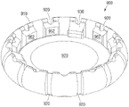
Figure 6A depicts a perspective view of a toric base assembly according to an embodiment of the present disclosure.
Figure 6B depicts a top plan view of the toric base component of figure 6A.
Figure 7A depicts a perspective view of a toric base assembly according to an embodiment of the present disclosure.
Figure 7B depicts a top plan view of the toric base component of figure 7A.
Fig. 8A depicts a perspective view of a base assembly according to an embodiment of the present disclosure.
Fig. 8B depicts a top plan view of the base assembly of fig. 8A.
FIG. 8C depicts a cross-sectional view of the base assembly of FIG. 8A.
Figure 9A depicts a perspective view of an accommodating IOL configured to position an optical power lens closer to a base lens of a base assembly according to an embodiment of the present disclosure.
Fig. 9B depicts a top plan view of the accommodating IOL of fig. 9A.
Figure 9C depicts a cross-sectional view of the accommodating IOL of figure 9A.
Figure 10A depicts an exploded perspective view of a low profile accommodating IOL according to an embodiment of the present disclosure.
Figure 10B depicts a perspective view of the low profile accommodating IOL of figure 10A.
Figure 10C depicts a top plan view of the low profile accommodating IOL of figure 10A.
Figure 10D depicts a perspective cross-sectional view of the low profile accommodating IOL of figure 10A.
Figure 11A depicts a perspective view of an accommodating IOL including a base assembly and a power lens with a fin-lock according to an embodiment of the present disclosure.
Figure 11B depicts an exploded perspective view of the accommodating IOL of figure 11A.
Fig. 11C depicts a top plan view of the accommodating IOL of fig. 11A.
Figure 11D depicts a cross-sectional view of the accommodating IOL of figure 11A.
Figure 12A depicts an exploded perspective view of an accommodating IOL having a base assembly and a power lens with plate haptics according to an embodiment of the present disclosure.
Figure 12B depicts an exploded plan view of the accommodating IOL of figure 12A.
Figure 12C depicts a top plan view of the power lens of the accommodating IOL of figure 12A.
Fig. 12D depicts a top plan view of the accommodating IOL of fig. 12A.
Fig. 12E depicts a cross-sectional view of the accommodating IOL of fig. 12A.
Figure 12F depicts a bottom perspective view of the accommodating IOL of figure 12A.
Fig. 13A depicts a perspective view of a base assembly having an extended tab according to an embodiment of the present disclosure.
Fig. 13B depicts a top plan view of the base assembly of fig. 13A.
FIG. 13C depicts a cross-sectional view of the base assembly of FIG. 13A.
Fig. 14A depicts a perspective view of a susceptor ring according to an embodiment of the present disclosure.
Fig. 14B depicts a top plan view of the susceptor ring of fig. 14A.
Fig. 14C depicts a cross-sectional view of the susceptor ring of fig. 14A.
Fig. 14D depicts an alternative cross-sectional view of the susceptor ring of fig. 14A.
Fig. 14E depicts a perspective view of a mesh braid that can be incorporated into the base ring of fig. 14D.
Figure 15A depicts a perspective view of an accommodating IOL having a one-piece base assembly and a power lens according to an embodiment of the present disclosure.
Figure 15B depicts a top plan view of the accommodating IOL of figure 15A.
Figure 15C depicts a cross-sectional view of the accommodating IOL of figure 15A.
Figure 15D depicts a bottom perspective view of the accommodating IOL of figure 15A.
Figure 16A depicts a perspective view of an accommodating IOL having a gapless base assembly according to an embodiment of the present disclosure.
Figure 16B depicts a side plan view of the accommodating IOL of figure 16A.
Fig. 16C depicts a perspective view of a gapless base assembly that can be used in the accommodating IOL of fig. 16A.
Figure 16D depicts a perspective view of a power lens that can be used in the accommodating IOL of figure 16A.
Fig. 16E depicts a top plan view of the accommodating IOL of fig. 16A.
Figure 16F depicts a cross-sectional view of the accommodating IOL of figure 16A.
Like reference numerals refer to like parts throughout the several views of the drawings.
Detailed Description
Specific, non-limiting embodiments of the present invention will now be described with reference to the accompanying drawings. It should be understood that such embodiments are exemplary and are only illustrative of a small number of embodiments that are within the scope of the present invention. Various changes and modifications apparent to those skilled in the art to which the invention pertains are deemed to be within the spirit, scope and contemplation of the invention.
Various embodiments of accommodating intraocular lenses (IOLs) described herein can include a power change characteristic of a power lens associated with a base lens. In an alternative embodiment, the optical power change characteristic of the IOL is driven by a fluid optic within the enclosed volume of the optical power lens comprising a flexible membrane and the lens or optic. One significant advantage of this embodiment is that the enclosed volume of the power lens separating the flexible membrane and the lens remains a substantially constant volume and thus avoids many of the problems associated with fluid optical IOLs that require a significant change in volume, i.e., fluid is supplied from a reservoir into the cavity. Many of the disadvantages exhibited by fluid optics having varying volumes include non-uniform optical power variation and buckling. Certain embodiments of the IOLs and power lenses disclosed herein can avoid or mitigate such problems by maintaining a substantially constant volume while maintaining good optical quality over the entire range of power variations. In addition, various embodiments of IOLs that include a two-part assembly of a power lens and base assembly as described herein provide a smaller delivery profile, a smaller implant profile, or both, requiring significantly smaller incision sizes for implantation. This, in turn, can have the attendant advantages of reducing biocompatibility issues associated with delivering and implanting larger IOLs, and can result in faster healing and more stable refraction.
The IOLs disclosed herein can be configured in any number of ways. In general, an IOL can include a base assembly and a power lens that can be coupled within the base assembly. In one embodiment, the radial compressive force exerted on the implanted IOL can be concentrated on the flexible membrane of the power lens to cause a change in curvature of the flexible membrane. The lens or optic of the optical power lens can be configured to be axially displaced toward the flexible membrane in response to a change in curvature of the flexible membrane. This axial displacement can be facilitated by coupling the optic to the peripheral edge of the IOL in a manner that allows the optic to float. As the curvature of the flexible membrane of the optical power lens changes, fluid adhesion or surface tension can pull the optic or lens of the optical power lens toward the flexible membrane. In another embodiment, a radially compressive force applied to the refractive power lens can be focused on the optic to cause axial displacement of the optic and urge the flexible membrane in the same direction as the axial displacement of the optic to effect a change in curvature of the flexible membrane. In yet another embodiment, a radially compressive force on the optical power lens can be applied to the optic and the flexible membrane to cause axial displacement and curvature change, respectively.
In another embodiment, a radially compressive force applied to the optical power lens can be applied to one or both of the flexible membrane and the optic to cause a change in curvature of the flexible membrane and to cause axial displacement of the optic toward the flexible membrane while maintaining a constant volume during radial compression.
In one embodiment, the term "constant volume" includes a volume that varies by no more than about 1% from its resting state, no more than about 2% from its resting state, no more than about 3% from its resting state, no more than about 4% from its resting state, no more than about 5% from its resting state, no more than about 10% from its resting state, no more than about 15% from its resting state, no more than about 20% from its resting state, no more than about 25% from its resting state, no more than about 30% from its resting state, no more than about 35% from its resting state, no more than about 40% from its resting state, no more than about 45% from its resting state, no more than about 50% from its resting state, no more than about 55% from its resting state, no more than about 60% from its resting state, No more than about 65% from its resting state, no more than about 70% from its resting state, and no more than about 75% from its resting state. In another embodiment, the term "constant volume" refers to a volume that varies within a range that includes and between any two of the foregoing values. The term "resting state" describes the configuration of an IOL or a refractive lens when no radial compressive force is exerted on the IOL or refractive lens.
As used herein, the term "refractive power lens" can refer to a component that provides a range of accommodation or refractive correction in response to the application of a radially compressive or expansive force. In one embodiment, the refractive power lens is capable of providing an accommodation range of about 1 diopter, about 2 diopters, about 3 diopters, about 4 diopters, about 5 diopters, about 6 diopters, about 7 diopters, about 8 diopters, about 9 diopters, about 10 diopters, about 11 diopters, about 12 diopters, about 13 diopters, about 14 diopters, about 15 diopters, about 16 diopters, about 17 diopters, about 18 diopters, about 19 diopters, or about 20 diopters. In another embodiment, the power lens is capable of providing a range of accommodation between and including any two of the foregoing values. The term "optical power lens" can also include a component comprising a first side, a second side, a peripheral edge coupling the first side and the second side, and an enclosed cavity configured to contain a fluid. In one aspect, the first side and the second side can be flexible films or optics. In another aspect, the first side can be one of a flexible film or an optical device, and the second side can be the other of the flexible film or the optical device. In yet another aspect, the optical power lens is further characterized by having an enclosed fluid-filled cavity with a constant volume throughout the accommodative range.
Certain embodiments of the two-part accommodating IOL devices disclosed herein can provide a number of advantages due to their separate two-part configuration. Implantation of a two-part IOL device can require significantly reduced incision size because the two parts of the IOL device (e.g., the base assembly and the power lens) are implanted separately and thus significantly reduce the delivery profile of the implant. The reduced incision size can provide a number of advantages, including the elimination of the need for anesthesia and suturing to close the incision site and improve the surgical outcome. In one embodiment, the incision size required to implant a two-part accommodating IOL device is less than about 5mm, less than about 4mm, less than about 3mm, or less than about 2 mm. In other words, each portion of the two-part accommodating IOL device can be provided in a delivery state with a delivery profile of less than about 5mm, less than about 4mm, less than about 3mm, or less than about 2 mm. The delivery state of each section of the two-section accommodating IOL device can be provided when each section is rolled, folded, or otherwise compressed to reduce its delivery size. Hinges or predetermined creases can be provided on one or both of the base component and the power lens to facilitate folding or rolling to the delivery state.
In addition, greater control is provided in adjusting the size and power of the IOL during surgery. Implanting the base assembly into the lens capsule will provide the physician with an impression of the size of the lens capsule of the patient and will therefore help to select the correct size of the lens for the power change that will subsequently be implanted into the base assembly.
Fig. 1A depicts a perspective view of an embodiment of a fluid-filled base assembly 100 of an accommodating IOL. Fig. 1B provides a cross-sectional view of the fluid-filled base assembly 100. The base assembly 100 shown in fig. 1A-1B can include a base lens 110 and a haptic system 120 disposed generally circumferentially about the base lens 110. Haptic system 120 is sized and configured to receive individual power lenses, such as power lenses 195, 350 depicted in fig. 1C and 3C, respectively. Power lenses 195, 350 can be inserted into base assembly 100 to form a two-part accommodating IOL device.
In one embodiment, the haptic system 120 can include a reservoir 130 extending through at least a portion of the haptic system 120. According to one aspect, the reservoir 130 can extend around a portion of the circumference of the haptic system 120, as depicted in fig. 2A-2C and 4B, such that the arc of the reservoir 130 is at least 90 degrees, at least 100 degrees, at least 110 degrees, at least 120 degrees, at least 130 degrees, at least 140 degrees, at least 150 degrees, at least 160 degrees, at least 170 degrees, at least 180 degrees, at least 190 degrees, at least 200 degrees, at least 210 degrees, at least 220 degrees, at least 230 degrees, at least 240 degrees, at least 250 degrees, at least 260 degrees, at least 270 degrees, at least 280 degrees, at least 290 degrees, at least 300 degrees, at least 310 degrees, at least 320 degrees, at least 330 degrees, at least 340 degrees, at least 350 degrees, or about 360 degrees. According to another aspect, the reservoir 130 can extend around a portion of the circumference of the haptic system 120 over a range (e.g., 180 radians to 270 radians) that includes and between any two of the aforementioned values. According to another aspect, the reservoir 130 can extend around the entire circumference (e.g., 360 radians) of the haptic system 120, as provided in the embodiment depicted in fig. 1A-1C.
The reservoir 130 can be defined or bounded by an inner region 180 and an outer region 150. The reservoir 130 is configured to contain a fluid (e.g., a liquid or a gas). In certain embodiments, the fluid can be selected from the group consisting of: silicone oils, fluorinated silicone oils, polyphenylene ethers and fluorinated polyphenylene ethers. The fluorinated polyphenylene ether can be one or a combination of pentafluoro-m-phenoxyphenyl ether and m- (pentafluorophenoxy) phenyl-m-phenoxyphenyl ether. The fluid contained within the reservoir 130 can be used to distribute a force applied to the outer region 150 of the haptic system 120 to the inner region 180. For example, the fluid contained within the reservoir 130 can be used to substantially uniformly transfer a compressive force (e.g., a force caused by ciliary muscle relaxation) applied to the outer region 150 of the haptics system 120 to the inner region 180. The forces transmitted to the inner region 180 can then be transmitted to a power lens (195, 350 as depicted in fig. 1C and 3C, respectively) coupled centrally within the base assembly 100. Alternatively or in addition, the forces transmitted to the inner region 180 can be transmitted to the base lens 110.
The fluid-filled base assembly 100 can include an upper flange 160 and a lower flange 170 extending inwardly from the haptic system 120 along at least a portion of the circumference of the haptic system 120. Upper flange 160 and lower flange 170 define a channel configured to secure optical power lens 195 to fluid-filled base assembly 100. Fig. 1C depicts an exploded perspective view of a power lens 195 inserted into base assembly 100, wherein a peripheral edge 197 of power lens 195 is adapted to fit within the channel defined by upper flange 160 and lower flange 170. Additionally, at least a portion of peripheral edge 197 (if not the entire peripheral edge 197) is configured to engage or directly contact inner region 180 so as to effectively transfer forces transferred to inner region 180 to one or both of first side 196 and second side 199 of optical power lens 195 to provide accommodation. As explained above, the first and second sides can be flexible films or optical devices, or alternatively, the first side can be one of a flexible film or an optical device and the second side can be the other of a flexible film or an optical device.
Fig. 2A depicts a perspective view of an open fluid-filled base ring 200 of an accommodating IOL. Fig. 2B and 2C depict a top plan view and a cross-sectional view, respectively, of the open fluid-filled susceptor ring 200. The open fluid-filled base ring 200 represents an alternative embodiment of the fluid-filled base assembly 100 discussed above with reference to fig. 1A-1C and can be used in conjunction with the optical power lens 195 depicted with respect to fig. 1C. The open fluid-filled susceptor ring 200 includes a haptic system 210. The open fluid-filled base ring 200 differs from the base assembly 100 of fig. 1 in that the open fluid-filled base ring 200 does not include a base lens. As such, any vision correction must be provided by an optical power lens 195 that can be inserted into the open fluid-filled base ring 200 in the manner depicted with respect to fig. 1C.
In one embodiment, the open fluid-filled susceptor ring 200 is a split ring, i.e., it is not a complete ring. In one embodiment, the open fluid-filled susceptor ring 200 is provided in a C-shape having two closed ends 210A, 210B, wherein its outer periphery is less than 360 radians. In another embodiment, the open fluid-filled susceptor ring 200 is provided in a circular shape of approximately 360 radians, but includes a pair of closed ends, such that the inner cavity 250 is not a continuous circumferential volume, but rather includes a circumferential volume having a pair of closed ends. Both embodiments allow the open fluid-filled base ring 200 to increase the diameter defined in the central region of the haptics 210 and accommodate optical power lenses of different diameters. The C-shaped or incomplete ring configuration can also allow for toric or non-uniform deformation of the optical power lens, as a portion of the periphery of the optical power lens will not contact the open fluid-filled base ring 200, and thus the non-contacting portion of the periphery of the optical power lens will not be subjected to the radially inward force exerted by the open fluid-filled base ring 200. Thus, in one embodiment, the open fluid-filled base ring 200 is capable of transmitting a radial compressive force only about a predetermined portion of the circumference of the periphery 197 of the optical power lens 195 disposed or coupled within the open fluid-filled base ring 200 so as to provide asymmetric radial compression of the optical power lens 195 implanted within the open fluid-filled base ring 200.
In one embodiment, the arc of the open fluid-filled susceptor ring 200 is at least 180 degrees, at least 190 degrees, at least 200 degrees, at least 210 degrees, at least 220 degrees, at least 230 degrees, at least 240 degrees, at least 250 degrees, at least 260 degrees, at least 270 degrees, at least 280 degrees, at least 290 degrees, at least 300 degrees, at least 310 degrees, at least 320 degrees, at least 330 degrees, at least 340 degrees, at least 350 degrees, or 360 degrees. In each of the foregoing embodiments, the angle defined by the circumference of the open fluid-filled susceptor ring is set within a range between any two of the foregoing values.
The open fluid-filled base ring 200 includes an upper flange 220 and a lower flange 230 forming a channel 240 between the upper flange 220 and the lower flange 230. Channel 240 can be configured to receive and fix a power lens. The haptic system 210 includes a reservoir 250 (see fig. 2C), the reservoir 250 extending through at least a portion of the haptic system 210, e.g., substantially around the entire haptic system 210. The haptic system 210 can include an inner wall 260 and an outer wall 270 that define the reservoir 250. In one embodiment, the thickness of the inner wall 260 can be less than the thickness of the outer wall 270. The thickness of the inner wall 260 can be about 90%, about 80%, about 70%, about 60%, about 50%, about 40%, about 30%, about 20%, about 10%, and about 5% of the thickness of the outer wall 270. The thickness of the inner wall 260 can also be within a range between and including any two of the foregoing values.
The reservoir 250 can be configured to contain a fluid. In certain embodiments, the fluid can be selected from the group consisting of: silicone oils, fluorinated silicone oils, polyphenylene ethers and fluorinated polyphenylene ethers. The fluorinated polyphenylene ether can be one or a combination of pentafluoro-m-phenoxyphenyl ether and m- (pentafluorophenoxy) phenyl-m-phenoxyphenyl ether. The fluid contained within the reservoir 250 may be used to distribute the force applied to the outer wall 270 of the haptic system 210 to the inner wall 240. For example, the fluid contained within reservoir 250 may be used to substantially uniformly transfer compressive forces applied to the periphery of haptic system 210, such as forces caused by contraction and/or relaxation of the ciliary muscle. The forces transmitted to the inner wall 260 can then be transmitted to the optical power lens housed within the channel 240.
Fig. 3A depicts a perspective view of a fluid-filled base ring 300 according to another embodiment of the present disclosure. Fig. 3B is a top plan view of the fluid-filled susceptor ring 300. The fluid-filled susceptor ring 300 is substantially similar to the open fluid-filled susceptor ring 200 of fig. 2A-2C, with the primary difference being that the fluid-filled susceptor ring 300 is a closed ring, rather than an open ring. The fluid-filled susceptor ring 300 can also include an annular haptics system 310. The fluid-filled base ring 300 can further include an upper flange 320 and a lower flange 330 extending radially inward from the haptics system 310. The upper flange 320 and the lower flange 330 together define a channel configured to secure an optical power lens within the central portion of the fluid-filled base ring 300. An inner wall 340 is defined between the upper flange 320 and the lower flange 330. As described above in connection with the embodiment of fig. 1 and 2, an external force applied to the outer wall of the haptic system 310 (e.g., through the ciliary muscle of the eye) can translate through the fluid-filled base ring 300 to the inner wall 340 (channel) of the haptic system 310 to apply a force to the optical power lens inserted in the channel.
Fig. 3C depicts an exploded perspective view of an optical power lens 350 configured to be coupled to the fluid-filled base ring 300. The fluid-filled base ring 300 is configured to fix an optical power lens 350 to form an accommodating IOL.
In various embodiments, optical power lens 350 includes a flexible membrane 352 on one side, an optic 354 on an opposite side, and a circumferential peripheral edge 358 coupling the flexible membrane and optic 354. Membrane coupler 356 can extend radially inward from an inner side of circumferential peripheral edge 358 to couple membrane 352 to peripheral edge 358. According to an optional aspect, at least a portion of the peripheral edge 358 is in direct contact with the inner wall 340 of the fluid-filled base ring 300. According to another alternative aspect, the entire peripheral edge 358 is in direct contact with the inner wall 340 of the fluid-filled base ring 300. The optical power lens 350 can include an optical coupler 360 extending radially inward from the inside of the circumferential peripheral edge 358 to couple the optic 354 to the peripheral edge 358. Preferably, optical coupler 360 is angled toward flexible film 352 such that it arches optical device 354 toward flexible film 352. See, e.g., exemplary cross-sectional views of the refractive power lens 920 of figure 9C and the refractive power lens 1020 of figure 10D. Thus, in one embodiment, the refractive power lens 350 can be the same as the refractive power lens 920 of fig. 9C or the refractive power lens 1020 of fig. 10D.
Other examples of accommodating intraocular lenses IOLs are disclosed in: U.S. patent application publication No.2013/0053954 entitled "Accommodating Intraocular lenses"; U.S. patent application publication No.2014/0180403 entitled "Accommodating Intraocular lenses"; U.S. patent application publication No.2015/0105760 entitled "Method and System for Adjusting the Refractive Power of an Implanted Intraocular Lens"; and U.S. patent application No.14/447,621 entitled "Accommodating Intraocular lenses," which is hereby incorporated by reference in its entirety as if fully set forth herein. Any of the features disclosed in the above references with respect to accommodating intraocular lenses can be applied to any of the base assemblies, refractive power lenses, or accommodating intraocular lenses disclosed herein. For example, the various integral accommodating IOL embodiments disclosed in U.S. patent application publication nos. 2013/0053954, 2014/0180403, and 2015/0105760 can be used as the power lens 350. U.S. patent application No.14/447,621 discloses a two-piece accommodating IOL that utilizes a base assembly and a power lens (sometimes referred to as an accommodating IOL or IOL) inserted into the base assembly. It should be understood that various embodiments are possible.
Fig. 4A depicts a perspective view of an optical power lens 350 coupled to a fluid-filled base ring 300. Fig. 4B depicts a perspective view of an optical power lens 350 coupled to the open fluid-filled base ring 200. According to one aspect, only at least a portion of the circumferential peripheral edge 358 is in direct physical contact with the inner wall 240, 340 of the fluid-filled base ring 200, 300 (see fig. 4B). According to another aspect, the entire circumferential edge 358 is in direct contact with the inner wall 340 of the fluid-filled base ring 300 (see fig. 4A).
Fig. 5A provides a perspective view of a fluid exchange optical power lens 500 according to an embodiment of the present disclosure. The power lens 500 shown in fig. 5A can include the components described with respect to the power lens 350 shown in fig. 3C, for example. In various embodiments, optical power lens 500 includes a reservoir for storing a fluid that can be delivered to a fluid-filled base assembly forming a portion of an accommodating IOL. The optical power lens 500 includes a fluid delivery valve 510, the fluid delivery valve 510 configured to be removably coupled to a fluid-filled base assembly (see fig. 5B). The fluid transfer valve 510 is used to provide fluid communication between the optical power lens 500 and the base assembly shown in fig. 1-4.
Fig. 5B depicts an embodiment of a fluid transfer system for transferring fluid between the optical power lens and the fluid-filled base assembly of an accommodating IOL. The fluid transfer valve 510 is configured to interact with a receiving valve 520 disposed on an inner wall of a fluid-filled base assembly (e.g., 180, 240, 340 of fig. 1B, 2A, 3A, respectively). In various embodiments, fluid delivery valve 510 can be implemented as part of optical power lens 500 and receiving valve 520 can be implemented as part of fluid-filled base assembly 590, or vice versa. The fluid transfer valve 510 includes a conduit 530 leading to a one-way valve 540. The receiving valve 520 includes a valve release conduit 550. The receiving valve 520 includes its own check valve 560. When fluid delivery valve 510 and receiving valve 520 are independent, both one- way valves 530, 560 are closed and no fluid escapes from optical power lens 500 or fluid-filled base assembly 590. When the tube 530 of the fluid transfer valve 510 is inserted into the check valve 560 of the fluid-filled base assembly 590, the tube 530 forces the check valve 560 open. Similarly, valve release conduit 550 forces one-way valve 540 open. As a result, both one- way valves 540, 560 are pushed open and fluid is able to flow freely between optical power lens 500 and fluid-filled base assembly 590.
Fig. 6 and 7 depict embodiments of toric base assemblies 600, 700. Base assemblies 600, 700 include base lenses 610, 710 and generally circular haptic systems 620, 720, haptic systems 620, 720 having an outer periphery and at least two regions of differing flexibility. Because at least two regions have greater flexibility 640, 730 than the rest of the haptic system 620, 720, applying a radially compressive force on the outer periphery of the haptic system 620, 720 results in asymmetric deformation of the haptic system 620, 720 in the more flexible region 640, 730. In other words, the more flexible region 640, 730 is radially compressed or compressible to a greater extent than the remaining regions of the haptic system 620, 720. This asymmetric deformation, in turn, can provide toric power variations in one or both of the base lenses 610, 710 and the power lenses provided within the haptic systems 620, 720.
Figures 6A-6B depict one embodiment of a toric base assembly 600. Figure 6A depicts a perspective view of a toric base assembly 600 of an accommodating toric IOL according to an embodiment of the present disclosure. Figure 6B provides a top plan view of the toric base assembly 600. Toric base assembly 600 includes a base lens 610 and a substantially circular haptic system 620. Toric base assembly 600 includes a plurality of tabs 630 to engage an inserted optical power lens (not shown). The outer periphery of haptic system 620 is configured to receive a deforming force caused by the ciliary muscle of the eye to cause radially inward compression of haptic system 620. These forces are then translated to one or both of the base lens 610 and/or a power lens that can be inserted into the base assembly 600. In the embodiment shown in fig. 6A and 6B, the portions of haptic system 620 have greater structural flexibility, resulting in uneven translation of the force applied radially inward by the various portions of haptic system 620. In the illustrated embodiment, an incision 640 is formed in haptic system 620 to create greater flexibility in the vicinity of incision 640. The cutout 640 can be formed to provide an area of the haptic 620 that is thinner than the remaining area of the haptic 620. As a result, haptic system 620 exerts a greater compressive force near incision 640, which in turn causes toric deformation of one or both of base lens 610 and the inserted power lens.
Fig. 7A and 7B provide perspective and top plan views, respectively, of an alternative toric base assembly 700 according to an embodiment of the present disclosure. Toric base assembly 700 includes a base lens 710 and a haptic system 720. In addition to having cuts 740 to create greater flexibility in certain areas of the haptic system 720, in the toric base assembly 700 shown in fig. 7A and 7B, the haptic system 720 also includes two extended regions 730 that extend beyond the circumference defined by the haptic system 720. The extended region 730 and the incision 740 result in an uneven distribution of compressive forces, resulting in toric deformation of one or both of the base lens 710 and the inserted power lens.
Accommodating IOLs can be provided with a base assembly that allows for a change in profile. The varying profile can be provided by configuring the base assembly such that the power lens is placed further away from the base lens (i.e., high profile) or closer to the base lens (i.e., low profile).
Fig. 8A-8C depict an embodiment of a high profile IOL base assembly 800. Fig. 8A depicts a perspective view of the base assembly 800, and fig. 8B and 8C depict top plan and cross-sectional views, respectively, of the base assembly 800.
Fig. 9 and 10 depict an embodiment of a low profile base assembly.
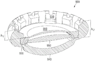
Fig. 9A depicts a perspective view of an accommodating intraocular lens 900 comprising a base component 900 and a power lens 920 coupled to the base component 910. In contrast to base assembly 800 of fig. 8A, base assembly 900 of accommodating IOL900 is configured to position optical power lens 920 deeper within base assembly 910 and closer to the base lens of base assembly 910. Figure 9B provides a top plan view of an accommodating IOL and figure 9C provides a cross-sectional view of an accommodating IOL including base assembly 900 and power lens 920. The accommodating IOL includes a power lens 920 secured in the base assembly 900 and held in place in part by a plurality of tabs 930 extending radially inward from the base assembly 900 into a central cavity within the base assembly 900. The bottom surface of tab 930 contacts the first side of optical power lens 920, similar to fig. 8C. As can be seen most clearly in fig. 9C, a power lens 920 is positioned near a base lens 940. In the illustrated embodiment, the power lens 920 includes a flexible membrane 950 and power lens optics 960. The flexible membrane 950 and the optical power lens optic are spaced apart and the fluid fills the space between the two. The power lens optics 960 and the base lens 940 are in proximity to each other.
The optical power of the accommodating IOL low profile magnifying accommodating IOL900 varies as will be described in more detail below with reference to figure 10.
Fig. 10A-10D depict another embodiment of a low-profile accommodating IOL 1000 in which a low-profile base assembly 1010 is configured to place a power lens 1020 deeper within the base assembly 1010, in close proximity to a base lens 1030, to create a potentially greater range of optical powers with a particular IOL configuration. Low-profile accommodating IOL 1000 includes a base assembly 1010 and a power lens 1020 configured to be secured within base assembly 1010. The base component 1010 includes haptic portions 1015 for translating forces applied to the periphery of the haptic portions 1015 to the power lens 1020.
As can be seen in the cross-sectional view of fig. 10D, the power lens 1020 includes a flexible membrane 1050 and power lens optics 1040, while the base assembly 1010 includes haptics 1015 for translating forces applied to the periphery of the haptics 1015 to the power lens 1020 and the base lens 1030. The base lens 1030 and the refractive lens optic 1040 approach each other and the power of the low profile, magnifying power lens 1020 of the accommodating IOL changes. The power change of the accommodating IOL 1000 is primarily produced by the accommodating power lens 1020. Furthermore, accommodation of the refractive lens 1020 is most effectively produced by applying force to the membrane 1050 rather than to the refractive lens optics 1040. As such, the power change of the accommodating IOL 1000 is most effective when the force applied to the periphery of the haptic 1015 is effectively translated to the membrane 1050.
The low-profile accommodating IOL 1000 effectively translates forces from the haptics 1015 to the membrane 1050 in several ways. First, placing the power lens 1020 deeper within the haptics 1015 results in more efficient translation of forces from the haptics 1015 to the power lens 1020 (which includes the membrane 1050). This is due, at least in part, to the fact that when the optical lens 1020 is positioned higher within the haptics 1015, a greater proportion of the force exerted on the periphery of the haptics 1015 is distributed to the base lens 1030, rather than the optical lens 1020. The portion of the force imparted to the base lens 1030 does not significantly affect accommodation and/or optical power changes and, therefore, cannot be effectively used to effect optical power changes of the accommodating IOL 1000. By moving the power lens 1020 lower within the haptics 1015, a greater proportion of the force is distributed to the power lens 1020 rather than being lost to the base lens 1030. Further, placing the power lens 1020 near the base lens 1030 allows the power lens 1020 to be closer to the hinge portion 1090, which hinge portion 1090 translates at least a portion of the force imparted to the base lens 1030 to the power lens 1020.
As described above, even if a force is applied to the refractive lens 1020, accommodation is maximized when a force is applied to the membrane 1050 instead of the refractive lens optic 1040. An incision 1080 on the lower portion of the periphery of the power lens 1020 results in the force being translated to the membrane 1050 instead of the power lens optics 1040. By removing the lower portion of the periphery of the refractive lens 1020 (the incision 1080), the haptics 1015 primarily engage the upper portion 1070 of the periphery of the refractive lens 1020 and force is exerted primarily on the membrane 1050 (which is on the upper portion of the refractive lens 1020) rather than on the refractive lens optic 1040 (which is on the lower portion of the refractive lens 1020), thereby affecting greater refractive power changes in the refractive lens 1020.
In the embodiment shown in fig. 8A-8C, the accommodating intraocular lens can have a higher profile than the embodiment shown in fig. 9 and 10. In other words, in the high profile embodiment, the refractive power lenses are positioned closer to the open end of the haptic system 810 and further away from the base lens 830 (fig. 8A-8C), while in the low profile embodiment, the refractive power lenses 920, 1020 are positioned further away from the open end and closer to the base lenses 940, 1030 (fig. 9A-9C and 10A-10D). In fig. 8C and 10D, the distance h of the peripheral edge of the reference power lens from the first edge of the outer periphery of the haptic1To indicate the position of the power lens.
Thus, according to one aspect, as h in FIG. 8C and FIG. 10D1As shown, the power lens is positioned at a predetermined distance from a first edge of the outer periphery of the haptic. In one aspect, the predetermined distance h1Can be about 0mm, about 0.1mm, about 0.15mm, about 0.2mm, about 0.25mm, about 0.30mm, about 0.35mm, about 0.40mm, about 0.45mm, about 0.50mm, about 0.55mm, about 0.60mm, about 0.65mm, about 0.70mm, about 0.75mm, about 0.80mm, about 0.85mm, about 0.90mm, about 0.95mm, about 1mm, about 1.1mm, about 1.15mm, about 1.2mm, about 1.25mm, about 1.3mm, about 1.35mm, about 1.4mm, about 1.45mm, about 1.5mm, about 1.55mm, about 1.6mm, about 1.65mm, about 1.7mm, about 1.75mm, about 1.8mm, about 1.85mm, about 1.9mm, about 1.95mm, and about 2 mm. In another aspect, the predetermined distance h1Can be provided within a range between and including any two of the foregoing values. Predetermined distance h of a high profile accommodating IOL, on the other hand1Can range from about 0mm to about 0.75 mm. In yet another aspect, the predetermined distance h of the low profile accommodating IOL1Can range from greater than 0.75mm to about 1 mm.
Predetermined distance h1Can also be set to the total height h as the outer perimeter of the haptic system 810, 10152Percentage of (c). In one aspect, the predetermined distance h1Can be the total height h of the outer perimeter of the haptic system 810, 10152About 0.01%, about 1%About 5%, about 10%, about 15%, about 20%, about 25%, about 30%, about 35%, about 40%, about 45%, about 50%, about 55%, about 60%, about 65%, about 70%, about 75%, about 80%, about 85%, and about 90%. In another aspect, the predetermined distance h1May be provided within a range between and including any two of the foregoing values. Predetermined distance h of a high profile accommodating IOL, on the other hand1Can be the total height h of the outer perimeter of the haptic system 810, 10152From about 0.01% to about 37%. In yet another aspect, the predetermined distance h of the high profile accommodating IOL1Can be the total height h of the outer perimeter of the haptic system 810, 10152From about 38% to about 75%.
Figure 11A depicts a perspective view of an accommodating IOL 1100 including a base assembly 1110 and a power lens 1120 in accordance with an embodiment of the present disclosure. Fig. 11B provides an exploded view of the accommodating IOL 1100, fig. 11C provides a top plan view of the accommodating IOL 1100, and fig. 11D provides a cross-sectional view of the accommodating IOL 1100. The base assembly 1110 includes a haptic system 1130. As best seen in fig. 11C, haptic system 1130 includes a plurality of recesses or cutouts 1140 defined within an inner periphery of haptic system 1130 for receiving one or more fins 1150 extending from the peripheral edge of optical power lens 1120. The plurality of recesses or cutouts 1140 can be defined by a raised portion or tab 1160 and an access passage on at least one side of the raised portion. The optical power lens 1120 is lowered into the base assembly 1110 such that each of the fins 1150 enters through one of the plurality of cuts 1140. The optical power lens 1120 is then rotated such that each fin 1150 is no longer positioned within one of the cuts 1140, but is positioned under one of the plurality of tabs 1160. Once each fin 1150 (or at least one of fins 1150) is positioned under tab 1160, optical power lens 1120 is secured to base assembly 1110. In certain embodiments, a manipulation aperture can be created on the optical power lens 1120 to allow a user to insert a tool into one or more manipulation apertures to assist in rotating the optical power lens 1120.
Fig. 12A-12F provide various views of an accommodating IOL 1200 according to an embodiment of the present disclosure. In this embodiment, accommodating IOL 1200 includes a base assembly 1210 and a power lens 1220. Base assembly 1210 includes a base lens 1290. Optical power lens 1220 includes flexible membrane 1230 and optics 1235 and flange 1240 extending outward from the peripheral edge of optical power lens 1220. The flange 1240 can be inserted into a channel 1250, the channel 1250 being formed in the inner perimeter of the base assembly 1240 or haptic by a plurality of upper tabs 1260 and lower tabs 1270. The positioning of flange 1240 towards the anterior portion of optical power lens 1220 can be advantageous because flange 1240 and tabs 1260 securing flange 1240 are positioned such that they do not interfere with the visual elements of the accommodating IOL, i.e., flexible membrane 1230, optics 1235, and base lens 1290. In this manner, visual artifacts or optical distortion caused by the flanges and tabs 1260, 1270 are minimized or eliminated altogether. Flange 1240 does not extend beyond optical lens 1220 at area 1280 to allow for easier insertion of optical lens 1220 into base assembly 1210.
Fig. 13A-13C depict an embodiment of a base assembly 1300 having extension tabs for an accommodating IOL. The base assembly 1300 includes a haptic system 1310 and a cavity 1320 for receiving an optical power lens. Extension tab 1330 extends over a portion of the circumference of haptic system 1310 and into the cavity. Extension tabs 1330 are used to secure the optical power lens within base assembly 1310. In certain embodiments, each tab 1330 can be measured by an angular coverage that indicates the portion of the circumference enclosed by each tab 1330. In certain embodiments, each tab 1330 can encompass between 30 and 180 degrees. Each tab 1330 can also include a width measurement that indicates how far the tab 1330 extends toward the center of the base assembly. The outer edges of the haptic system 1310 and applicable haptic systems described in this disclosure can be about 1mm thick.
Fig. 14A-14D depict various views of a non-astigmatic base ring 1400 according to embodiments of the present disclosure. Astigmatism-free base ring 1400 is a fluid-filled base ring configured to receive an optical power lens in the manner described with reference to fig. 1C and 3C. The non-astigmatic base ring 1400 includes a haptic system 1410 and can be arranged in a ring shape to surround an area 1420. A power lens can be inserted into the region 1420 to form an accommodating IOL. The astigmatism-free base ring 1400 includes an upper flange 1430 and a lower surface 1435 to secure a power lens between the upper flange 1430 and the lower surface 1435.
Fig. 14C provides a cross-sectional view of the astigmatism-free base ring 1400. The astigmatism-free base ring 1400 can include an outer reservoir 1440 and an inner reservoir 1450. The outer reservoir 1440 and the inner reservoir 1450 can contain a fluid and can be in fluid communication with each other. In one embodiment, the outer reservoir 1440 and the inner reservoir 1450 can be disposed in fluid communication with each other through a channel 1460 that is narrower than at least one of the outer reservoir 1440 and the inner reservoir 1450. The use of two reservoirs 1440, 1450 in fluid communication with each other through a narrow channel 1460 more evenly distributes the radial compressive force on the inner surface of the susceptor ring 1400 between the upper flange 1420 and the lower surface 1435 as the radial compressive force is applied to the periphery of the haptic system 1410. In this manner, a more uniform non-toric deformation is produced in the accommodating IOL.
FIG. 14D provides a cross-sectional view of an alternative embodiment of a astigmatism-free base ring 1400. In certain embodiments, a mesh braid, such as the mesh braid shown in fig. 14E, can be incorporated into the inner reservoir 1450. In certain embodiments, the mesh braid can comprise a Nitinol (Nitinol) braid. The mesh braid (fig. 14E) can allow fluid to flow between the inner reservoir 1450 and the outer reservoir 1440 while providing additional structural support for the inner reservoir, thereby facilitating even distribution of forces applied to the light scattering-free base ring 1400. Thus, in one embodiment, the above-described susceptor ring 1400 can further comprise a porous support structure or mesh braid, such as shown in fig. 14E, which can be disposed along a portion of the inner reservoir 1450 or along the entire inner reservoir 1450.
Fig. 15A depicts a perspective view of accommodating IOL 1500 having a base assembly and power lenses attached or attachable to each other by adhesion or insert molding. Fig. 15B provides a top plan view of accommodating IOL 1500. Fig. 15C depicts a cross-sectional view of accommodating IOL 1500. Fig. 15D depicts a bottom perspective view of accommodating IOL 1500. Accommodating IOL 1500 includes a haptic base component 1510 attached to a power lens 1520 during manufacture. This attachment can be accomplished by one or both of adhesive or insert molding, where one of the base component 1510 and the optical power lens 1520 is molded, and then the other of the base component 1510 and the optical power lens 1520 is molded directly onto the first molded portion (i.e., base component 1510 or optical power lens 1520). The portion of the power lens 1520 attached to the base component 1510 can be one or both of a portion of the circumferential peripheral edge 1522 or the posterior edge 1524 of the power lens 1520. The entire accommodating IOL 1500 can then be inserted into the patient. To reduce the volume of the cemented base and power lens, accommodating IOL 1500 can include only a single optic, such that the power correction comes only from power lens 1520. Thus, in one embodiment, base component 1510 does not itself include optics that provide refractive correction, and IOL 1500 includes only a refractive power lens 1520 that provides refractive correction.
Figures 16A-16F depict various views of a gapless accommodating IOL 1600 that includes a gapless base assembly 1610 and a power lens 1620. The gapless base assembly 1610 includes a base lens 1630 and a haptic system 1640. The base lens 1630 and haptic system 1104 are fixed together so no gap is formed to the power lens 1620. This limits the ability of the cells to flow into the cavity 1670 between the base lens 1630 and the power lens 1620 as the power lens 1620 is inserted into the gapless base assembly 1610. In various embodiments, a similar effect can be achieved by applying a parylene coating to the base assembly with gaps to prevent cells from moving into and out of the cavity between the power lens and the base lens.
In various embodiments, the base assembly described herein is capable of providing partial power correction. As a result, the base assembly can be installed and an appropriate power lens can be selected to be installed to allow correction within 1/4 diopters. Further, in various embodiments, the optics of the base assembly can include a UV absorber or UV absorber coating to absorb UV entering the patient's eye. In various embodiments, Purkinje (Purkinje) images can be used to adjust the power lens or base assembly to ensure that they are properly installed during installation of the accommodating IOL.
In various embodiments, the two-part accommodating intraocular lenses disclosed herein allow for more efficient inventorizing of products by using a power lens and a base assembly, such as the base assembly described in the present disclosure. For example, 4 base components and 9 power lenses are required to cover the range of 12 diopters to 27.5 diopters in half diopter steps. Using a single lens requires 32 different lenses. Since only 4 base assemblies and 9 power lenses are required, only 13 stock keeping units (hereinafter "SKUs") are required to store and organize the power lenses and base assemblies, rather than 32 different SKUs. This reduces the chance of dislocation and makes the organization easier. This increase in efficiency is even greater relative to a toric lens. For example, assuming 4 different toric powers, 128 SKUs are required to organize the lens for 32 single lens types. However, for a two-part accommodating IOL, assuming 4 different toric powers for the base assembly, only 16 base assemblies and 9 power lenses are required, for a total of 25 SKUs, which is significantly less than the 128 SKUs required for a single toric lens.
In various embodiments, the tabs and flanges of the base assembly discussed herein can be colored differently than the power lens to allow the surgeon to see when the power lens is properly inserted into the base assembly. In various embodiments, the optical power lens or the edge of the optical power lens can be colored to further aid in insertion of the optical power lens into the base assembly. In various embodiments, the base lens or haptic system of the base assembly can be colored. The coloration can be achieved by adding roughness or a coating to the outer surface of any of the aforementioned components.
In various embodiments, the purkinje image can be used to aid in the adjustment and placement of the power lens into the base assembly. After implantation, the image can be used to adjust the power lens and the base lens to ensure an optimal fit. This method provides immediate and easy feedback to the surgeon through the eyepiece of the scope. For example, if the surgeon is able to see a perfect circle when looking through the sight, the surgeon can receive an indication that the power lens is properly placed in the base lens. If the circle is deformed or misshapen, the surgeon will know that they must continue to adjust the power lens.
Claims (32)
1. An accommodating intraocular lens device comprising:
a low-profile base component comprising a first open end, a second end coupled to the base lens and positioned posteriorly relative to the first open end, and a haptic surrounding a central cavity, wherein the haptic comprises an outer perimeter, an inner surface, and a height between a first edge and a second edge, the first edge being anterior to the second edge; and
an optical power lens configured to fit within the central cavity, the optical power lens comprising a first side, a second side, a peripheral edge coupling the first side and the second side, and an enclosed cavity configured to contain a fluid, wherein the second side is configured to be spaced apart from the base lens by a portion of the central cavity, the peripheral edge is configured to contact the inner surface of the haptic, and the enclosed cavity is spaced apart from the first side and second side, the first side being in front of the second side;
wherein the first side of the optical power lens is positioned posterior to and 38% to 75% of the height of the haptic from the first edge of the haptic such that radial forces applied to the outer periphery of the haptic are concentrated on the first side of the optical power lens to cause a change in curvature of the first side.
2. The accommodating intraocular lens device of claim 1, wherein the change in curvature of the first side causes fluid contained in the enclosed cavity to pull the second side in a direction of the first side.
3. The accommodating intraocular lens device of claim 1, wherein the first side of the optical power lens is positioned about 0.75mm to about 1.5mm from the first edge of the haptic.
4. The accommodating intraocular lens device of claim 1, wherein the radial force applied to the outer periphery of the haptic is transmitted to the optical power lens in a greater proportion than the base lens.
5. The accommodating intraocular lens device of claim 1, wherein the inner surface faces the central cavity and comprises a plurality of spaced apart contact points configured to engage a portion of the peripheral edge of the optical power lens.
6. The accommodating intraocular lens device of claim 5, further comprising an outer groove extending along at least a portion of the height of the haptic, the outer groove configured to allow the haptic to be radially compressed, radially expanded, or both.
7. The accommodating intraocular lens device of claim 6, wherein the outer groove is disposed in the outer periphery opposite the inner surface contact point.
8. The accommodating intraocular lens device of any one of the preceding claims, wherein the haptic further comprises a plurality of tabs extending radially inward into the cavity, and wherein the optical power lens is secured to the base assembly by the plurality of tabs.
9. The accommodating intraocular lens device of claim 8, wherein the haptic further comprises a plurality of lands positioned posteriorly relative to the plurality of tabs and extending radially inward into the cavity, and wherein a channel is formed between the plurality of tabs and the plurality of lands to secure the optical power lens to the base assembly.
10. The accommodating intraocular lens device of claim 8, wherein the plurality of tabs comprises three tabs.
11. The accommodating intraocular lens device of claim 8, wherein a posterior surface of the plurality of tabs is positioned at a distance of about 0.75mm to about 1mm from the first edge of the haptic.
12. The accommodating intraocular lens device of claim 8, wherein a posterior surface of the plurality of tabs is positioned at a distance from the first edge of the haptic of about 38% to about 75% of the height of the haptic.
13. The accommodating intraocular lens device of claim 1, further comprising a plurality of arms coupling the base lens to the haptics.
14. The accommodating intraocular lens device of claim 13, wherein the arm arches the base lens away from the central cavity.
15. The accommodating intraocular lens device of claim 1, wherein the first side of the optical power lens comprises one of a flexible membrane or an optic, and wherein the second side of the optical power lens comprises the other of the flexible membrane or the optic.
16. The accommodating intraocular lens device of claim 15, wherein the optical power lens further comprises an optical coupler disposed from the peripheral edge to couple the optic to the peripheral edge, and wherein the optical coupler is angled to vault the optic toward the flexible membrane.
17. The accommodating intraocular lens device of claim 1, wherein the fluid is one or a combination selected from the group consisting of: silicone oils, fluorinated silicone oils, polyphenylene ethers and fluorinated polyphenylene ethers.
18. The accommodating intraocular lens device of claim 17, wherein the fluid is one or a combination of fluorinated polyphenylene ethers selected from the group consisting of: pentafluoro-m-phenoxyphenyl ether and m- (pentafluorophenoxy) phenyl-m-phenoxyphenyl ether.
19. An accommodating intraocular lens device comprising:
a low profile base assembly comprising a first open end, a second end comprising a base lens and positioned posteriorly relative to the first open end, and a haptic surrounding the base lens, the haptic comprising an outer perimeter surrounding a cavity and a height between a first edge and a second edge, the first edge being anterior to the second edge;
a power lens comprising a first side, a second side, and an enclosed cavity therebetween, the first side being anterior to the second side, and wherein the power lens is sized to fit within the cavity such that a portion of the cavity spaces the power lens from the base lens when the power lens is placed in the cavity; and
a retention system configured to secure the optical power lens within the cavity such that a first side of the optical power lens is positioned behind and 38% to 75% of the height of the haptic from the first edge of the haptic such that a radial force applied to the outer periphery of the haptic is concentrated on the first side of the optical power lens to cause a change in curvature of the first side.
20. The accommodating intraocular lens device of claim 19, wherein the retention system comprises a plurality of tabs extending radially inward from the haptics and into the cavity.
21. The accommodating intraocular lens device of claim 20, wherein the plurality of tabs are distributed circumferentially around the cavity.
22. The accommodating intraocular lens device of claim 21, wherein a posterior surface of each of the plurality of tabs is positioned at a distance from a first edge of the haptic of about 38% to about 75% of the height of the haptic.
23. The accommodating intraocular lens device of claim 22, wherein the plurality of tabs comprises three tabs.
24. The accommodating intraocular lens device of claim 20, wherein a coloration of the plurality of tabs is different from a coloration of the refractive power lens to allow visual confirmation that a refractive power lens is secured within the cavity by the retention system.
25. The accommodating intraocular lens device of claim 19, wherein a channel is formed between a pair of opposing tabs extending from an inner periphery of the haptic, wherein the channel is configured to receive the optical power lens.
26. The accommodating intraocular lens device of claim 21, wherein the plurality of tabs are evenly distributed around the cavity.
27. The accommodating intraocular lens device of any one of claims 19-26, wherein the haptic is substantially circular.
28. An accommodating intraocular lens device comprising:
a base assembly comprising a first open end, an open second end positioned rearwardly relative to the first open end, and a generally circular haptic surrounding the open second end, the generally circular haptic comprising an outer periphery and an inner periphery facing the cavity and a height between a first edge and a second edge, the first edge being forward of the second edge;
an optical power lens sized to fit within the cavity such that a portion of the cavity spaces the optical power lens from the open second end, wherein the optical power lens comprises a circumferential peripheral edge and a closed cavity configured to contain a fluid, and wherein at least a portion of the circumferential peripheral edge engages the inner periphery of the generally circular haptic;
wherein a first anterior side of the optical power lens is positioned posterior to and 38% to 75% of the height of the generally circular haptic from a first edge of the generally circular haptic such that radial forces applied to the outer periphery of the haptic are concentrated on the first anterior side of the optical power lens to cause a change in curvature of the first anterior side.
29. The accommodating intraocular lens device of claim 28, wherein the change in curvature of the first anterior side causes fluid contained in the closed cavity to pull a second posterior side of the optical power lens in a direction of the first anterior side.
30. The accommodating intraocular lens device of claim 28, wherein a portion of the optical power lens is attached to the substantially circular haptics.
31. The accommodating intraocular lens device of claim 30, wherein the portion of the optical power lens attached to the substantially circular haptic is one or both of the circumferential peripheral edge or posterior edge of the optical power lens.
32. The accommodating intraocular lens device of claim 30, wherein the optical power lens is attached to the substantially circular haptics by one or a combination selected from the group consisting of adhesives and insert molding.
Priority Applications (1)
| Application Number | Priority Date | Filing Date | Title |
|---|---|---|---|
| CN202110377284.6A CN113180886A (en) | 2015-12-01 | 2016-12-01 | Accommodating intraocular lens device |
Applications Claiming Priority (3)
| Application Number | Priority Date | Filing Date | Title |
|---|---|---|---|
| US201562261790P | 2015-12-01 | 2015-12-01 | |
| US62/261,790 | 2015-12-01 | ||
| PCT/US2016/064491 WO2017096087A1 (en) | 2015-12-01 | 2016-12-01 | Accommodating intraocular lens device |
Related Child Applications (1)
| Application Number | Title | Priority Date | Filing Date |
|---|---|---|---|
| CN202110377284.6A Division CN113180886A (en) | 2015-12-01 | 2016-12-01 | Accommodating intraocular lens device |
Publications (2)
| Publication Number | Publication Date |
|---|---|
| CN108778185A CN108778185A (en) | 2018-11-09 |
| CN108778185B true CN108778185B (en) | 2021-04-27 |
Family
ID=58797835
Family Applications (2)
| Application Number | Title | Priority Date | Filing Date |
|---|---|---|---|
| CN202110377284.6A Pending CN113180886A (en) | 2015-12-01 | 2016-12-01 | Accommodating intraocular lens device |
| CN201680080372.7A Active CN108778185B (en) | 2015-12-01 | 2016-12-01 | Accommodating intraocular lens device |
Family Applications Before (1)
| Application Number | Title | Priority Date | Filing Date |
|---|---|---|---|
| CN202110377284.6A Pending CN113180886A (en) | 2015-12-01 | 2016-12-01 | Accommodating intraocular lens device |
Country Status (6)
| Country | Link |
|---|---|
| US (3) | US11065107B2 (en) |
| EP (1) | EP3383320A4 (en) |
| JP (2) | JP6900376B2 (en) |
| CN (2) | CN113180886A (en) |
| AU (2) | AU2016362384B2 (en) |
| WO (1) | WO2017096087A1 (en) |
Families Citing this family (36)
| Publication number | Priority date | Publication date | Assignee | Title |
|---|---|---|---|---|
| EP2563275A4 (en) | 2010-04-27 | 2017-11-22 | Lensgen, Inc | Accommodating intraocular lens device |
| US9220590B2 (en) | 2010-06-10 | 2015-12-29 | Z Lens, Llc | Accommodative intraocular lens and method of improving accommodation |
| US9364318B2 (en) | 2012-05-10 | 2016-06-14 | Z Lens, Llc | Accommodative-disaccommodative intraocular lens |
| WO2015066502A1 (en) | 2013-11-01 | 2015-05-07 | Thomas Silvestrini | Accomodating intraocular lens device |
| EP3062742B1 (en) | 2013-11-01 | 2021-12-01 | Lensgen, Inc. | Two-part accommodating intraocular lens device |
| US9668916B2 (en) | 2013-11-04 | 2017-06-06 | Vance M. Thompson | Conjunctival cover and methods therefor |
| AU2015236131B2 (en) | 2014-03-28 | 2019-05-30 | Forsight Vision6, Inc. | Accommodating intraocular lens |
| US10004596B2 (en) | 2014-07-31 | 2018-06-26 | Lensgen, Inc. | Accommodating intraocular lens device |
| WO2016049059A1 (en) | 2014-09-23 | 2016-03-31 | Lensgen, Inc. | Polymeric material for accommodating intraocular lenses |
| US9869883B2 (en) | 2015-03-11 | 2018-01-16 | Vance M. Thompson | Tear shaping for refractive correction |
| WO2017096087A1 (en) | 2015-12-01 | 2017-06-08 | Daniel Brady | Accommodating intraocular lens device |
| CN109789012A (en) | 2016-05-27 | 2019-05-21 | 雷恩斯根公司 | The crystalline lens oil with Narrow Molecular Weight Distribution for intraocular lens body device |
| WO2018039353A1 (en) | 2016-08-24 | 2018-03-01 | Z Lens, Llc | Dual mode accommodative-disacommodative intraocular lens |
| US10353220B2 (en) | 2016-10-17 | 2019-07-16 | Vance M. Thompson | Tear shaping for refractive correction |
| US11523898B2 (en) | 2016-10-28 | 2022-12-13 | Forsight Vision6, Inc. | Accommodating intraocular lens and methods of implantation |
| EP3703614A4 (en) * | 2017-05-09 | 2021-01-06 | Khalid Mentak | Spectacle-free accommodating lens (sfal) |
| US11382736B2 (en) * | 2017-06-27 | 2022-07-12 | Alcon Inc. | Injector, intraocular lens system, and related methods |
| AU2018330604A1 (en) | 2017-09-11 | 2020-04-02 | Amo Groningen B.V. | Methods and apparatuses to increase intraocular lenses positional stability |
| CN117323062A (en) | 2017-11-01 | 2024-01-02 | 爱尔康公司 | Stabilization of intraocular lenses and peripheral portions |
| EP3494885A1 (en) * | 2017-12-07 | 2019-06-12 | Koninklijke Philips N.V. | Apparatus for presentation of dark field x-ray image information |
| WO2019123391A1 (en) * | 2017-12-20 | 2019-06-27 | Novartis Ag | Fluid-filled haptic for an intraocular lens |
| US10678067B2 (en) | 2018-04-06 | 2020-06-09 | Vance M. Thompson | Tear shaping for refractive correction |
| US20190374334A1 (en) * | 2018-06-07 | 2019-12-12 | Lensgen, Inc. | Intraocular lens device and related methods |
| US20200085564A1 (en) | 2018-09-18 | 2020-03-19 | Vance M. Thompson | Structures and methods for tear shaping for refractive correction |
| WO2020100160A1 (en) * | 2018-11-12 | 2020-05-22 | Abhijeet Khake | Intraocular lens assembly |
| WO2020197386A1 (en) | 2019-03-25 | 2020-10-01 | Akkolens International B.V. | Intraocular lens combination for restoration of refraction and accommodation |
| EP3968901A1 (en) | 2019-05-15 | 2022-03-23 | Akkolens International B.V. | Accommodating intraocular lenses with combination of mechanical driving components |
| WO2021034187A1 (en) | 2019-08-19 | 2021-02-25 | Akkolens International B.V. | Accommodative intraocular lens combination with independent fixed and variable power lens sections |
| US20230044397A1 (en) * | 2019-12-11 | 2023-02-09 | Lensgen, Inc. | Fluid lens component for intraocular lens and methods of preparing the same |
| DE102019134386A1 (en) | 2019-12-13 | 2021-06-17 | Carl Zeiss Meditec Ag | Intraocular lens |
| NL2027301B1 (en) | 2020-01-13 | 2021-10-26 | Akkolens Int B V | Mechanical means for accommodative intraocular lens |
| WO2021209955A1 (en) * | 2020-04-16 | 2021-10-21 | Alcon Inc. | Multi-part iol with stable iol base design to support a second optic |
| NL2028038B1 (en) | 2020-05-11 | 2022-07-04 | Akkolens Int B V | Method to connect and distance hydrophilic intraocular lens elements |
| CA3198430A1 (en) * | 2020-10-12 | 2022-04-21 | Omega Ophthalmics Llc | Prosthetic capsular devices, systems, and methods |
| AU2022373319A1 (en) * | 2021-10-18 | 2024-05-09 | Anew Iol Technologies, Inc. | Three-dimensional intraocular lens scaffold and add-in lens combination and methods of implantation |
| IL290086B2 (en) * | 2022-01-24 | 2023-04-01 | Eyemed Tech Ltd | Intraocular lens holding devices |
Citations (1)
| Publication number | Priority date | Publication date | Assignee | Title |
|---|---|---|---|---|
| US5800533A (en) * | 1996-03-18 | 1998-09-01 | Harry C. Eggleston | Adjustable intraocular lens implant with magnetic adjustment facilities |
Family Cites Families (426)
| Publication number | Priority date | Publication date | Assignee | Title |
|---|---|---|---|---|
| US4032502A (en) | 1975-10-10 | 1977-06-28 | Dow Corning Corporation | Organosiloxane compositions for liquid injection |
| US4073014A (en) | 1976-05-28 | 1978-02-14 | Stanley Poler | Intra-ocular lens |
| US4373218A (en) | 1980-11-17 | 1983-02-15 | Schachar Ronald A | Variable power intraocular lens and method of implanting into the posterior chamber |
| US4512040A (en) | 1982-06-09 | 1985-04-23 | Mcclure Hubert L | Bifocal intraocular lens |
| US4720286A (en) | 1984-07-20 | 1988-01-19 | Bailey Kelvin E | Multifocus intraocular lens |
| US4585457A (en) | 1985-05-16 | 1986-04-29 | Kalb Irvin M | Inflatable intraocular lens |
| US4676791A (en) | 1985-08-01 | 1987-06-30 | Surgidev Corporation | Intraocular lens and method for making same |
| US4731078A (en) | 1985-08-21 | 1988-03-15 | Kingston Technologies Limited Partnership | Intraocular lens |
| US5059668A (en) | 1986-01-20 | 1991-10-22 | Shin-Etsu Chemical Co., Ltd. | Fluorosilicone rubber composition |
| US5236970A (en) | 1987-02-05 | 1993-08-17 | Allergan, Inc. | Optically clear reinforced silicone elastomers of high optical refractive index and improved mechanical properties for use in intraocular lenses |
| US4842601A (en) | 1987-05-18 | 1989-06-27 | Smith S Gregory | Accommodating intraocular lens and method of implanting and using same |
| US5074876A (en) | 1987-12-04 | 1991-12-24 | Kelman Charles D | Two piece intraocular lens |
| US4888012A (en) | 1988-01-14 | 1989-12-19 | Gerald Horn | Intraocular lens assemblies |
| DE68920167T2 (en) | 1988-02-12 | 1995-06-29 | Menicon Co Ltd | Method of making an intraocular lens balloon. |
| US4822360A (en) | 1988-03-16 | 1989-04-18 | University Of Utah | Inflatable, intraocular lens and method of implanting the lens in the capsule of an eye |
| US4932966A (en) | 1988-08-15 | 1990-06-12 | Storz Instrument Company | Accommodating intraocular lens |
| US4882368A (en) | 1988-09-26 | 1989-11-21 | Dow Corning Corporation | Low compression set fluorosilicone rubber |
| US4892543A (en) | 1989-02-02 | 1990-01-09 | Turley Dana F | Intraocular lens providing accomodation |
| US5227447A (en) | 1989-12-07 | 1993-07-13 | Shin-Etsu Chemical Co., Ltd. | Preparation of high molecular weight organopolysiloxane |
| US5152788A (en) | 1989-12-27 | 1992-10-06 | Minnesota Mining And Manufacturing Company | Multifocal diffractive ophthalmic lens and method of manufacture |
| JPH03202102A (en) | 1989-12-28 | 1991-09-03 | Toray Dow Corning Silicone Co Ltd | Method for reducing amount of siloxane oligomer in organopolysiloxane molded product |
| US6197059B1 (en) | 1990-04-27 | 2001-03-06 | Medevec Licensing, B.V. | Accomodating intraocular lens |
| US5217491A (en) | 1990-12-27 | 1993-06-08 | American Cyanamid Company | Composite intraocular lens |
| CN1064611A (en) | 1991-03-11 | 1992-09-23 | 罗伯特·G·威利 | Intraocular lens with variable optical strength of astigmatism correction ability |
| WO1992017132A1 (en) | 1991-03-25 | 1992-10-15 | Albert Daxer | Artificial eye-lens |
| FR2681524B1 (en) | 1991-09-25 | 1997-04-04 | Mnao | CRYSTALLINE IMPLANT. |
| US5171773A (en) | 1991-11-13 | 1992-12-15 | Dow Corning Corporation | High strength fluorosilicone rubber |
| US5275623A (en) | 1991-11-18 | 1994-01-04 | Faezeh Sarfarazi | Elliptical accommodative intraocular lens for small incision surgery |
| US20040015236A1 (en) | 1991-11-18 | 2004-01-22 | Sarfarazi Faezeh M. | Sarfarazi elliptical accommodative intraocular lens for small incision surgery |
| US5278258A (en) | 1992-05-18 | 1994-01-11 | Allergan, Inc. | Cross-linked silicone polymers, fast curing silicone precursor compositions, and injectable intraocular lenses |
| US5306297A (en) * | 1992-07-06 | 1994-04-26 | Kabi Pharmacia Ophthalmics, Inc. | Intraocular lens haptic with enlarged anchoring head |
| US5312860A (en) | 1992-09-10 | 1994-05-17 | Shin-Etsu Chemical Co., Ltd. | Heat-curable silicone rubber composition and cured product thereof |
| US5264522A (en) | 1992-09-10 | 1993-11-23 | Shin-Etsu Chemical Co., Ltd. | Heat-curable fluorosilicone rubber composition and cured product thereof |
| US5443506A (en) | 1992-11-18 | 1995-08-22 | Garabet; Antoine L. | Lens with variable optical properties |
| US5336487A (en) | 1993-03-05 | 1994-08-09 | Refojo Miguel F | Method of treating eye disorders with silicon/fluorosilicone copolymer oil |
| US5447987A (en) | 1993-12-24 | 1995-09-05 | Shin-Etsu Chemical Co., Ltd. | Organopolysiloxane compositions |
| KR100346485B1 (en) | 1994-01-31 | 2002-11-30 | 바슈 앤드 롬 인코포레이티드 | Treatment Method of Contact Lens Using Supercritical Fluid |
| US5489302A (en) | 1994-05-24 | 1996-02-06 | Skottun; Bernt C. | Accommodating intraocular lens |
| EP0767809B1 (en) | 1994-06-30 | 2004-01-21 | Minnesota Mining And Manufacturing Company | Cure-indicating molding and coating composition |
| US5607472A (en) | 1995-05-09 | 1997-03-04 | Emory University | Intraocular lens for restoring accommodation and allows adjustment of optical power |
| US5774274A (en) | 1995-05-12 | 1998-06-30 | Schachar; Ronald A. | Variable focus lens by small changes of the equatorial lens diameter |
| JPH09150002A (en) | 1995-11-29 | 1997-06-10 | Shin Etsu Chem Co Ltd | Refining method for silicone oil |
| US5665794A (en) | 1996-05-20 | 1997-09-09 | Dow Corning Corporation | Method for controlling cure initiation and curing times of platinum group metal curing fluorosilicone compositions |
| DE19654488A1 (en) | 1996-12-27 | 1998-07-02 | Sueddeutsche Kalkstickstoff | Process for the fractionation of viscous silicones |
| US5854310A (en) | 1997-07-21 | 1998-12-29 | Dow Corning Corporation | Curable fluorosilicone composition having improved lubricity |
| FR2778093B1 (en) | 1998-05-04 | 2000-06-16 | Khalil Hanna | INTRAOCULAR IMPLANT |
| US6361561B1 (en) | 1998-10-13 | 2002-03-26 | Pharmacia & Upjohn Ab | Injectable intraocular lens |
| FR2784575B1 (en) | 1998-10-15 | 2000-12-22 | Megaoptic Gmbh | ACCOMMODATIVE INTRAOCULAR IMPLANT |
| US6197057B1 (en) | 1998-10-27 | 2001-03-06 | Gholam A. Peyman | Lens conversion system for teledioptic or difractive configurations |
| US6117171A (en) | 1998-12-23 | 2000-09-12 | Skottun; Bernt Christian | Encapsulated accommodating intraocular lens |
| US7662179B2 (en) | 1999-04-09 | 2010-02-16 | Sarfarazi Faezeh M | Haptics for accommodative intraocular lens system |
| US8556967B2 (en) | 1999-04-09 | 2013-10-15 | Faezeh Mona Sarfarazi | Interior bag for a capsular bag and injector |
| US6200581B1 (en) | 1999-04-28 | 2001-03-13 | Dow Corning Corporation | Elastomeric silicone terpolymer |
| US20060238702A1 (en) | 1999-04-30 | 2006-10-26 | Advanced Medical Optics, Inc. | Ophthalmic lens combinations |
| US20030060881A1 (en) | 1999-04-30 | 2003-03-27 | Advanced Medical Optics, Inc. | Intraocular lens combinations |
| US6200342B1 (en) | 1999-05-11 | 2001-03-13 | Marie-Jose B. Tassignon | Intraocular lens with accommodative properties |
| US6201091B1 (en) | 1999-08-20 | 2001-03-13 | Dow Corning Corporation | Organofunctional cocyclic siloxanes and polymerization thereof |
| US6767363B1 (en) | 1999-11-05 | 2004-07-27 | Bausch & Lomb Surgical, Inc. | Accommodating positive and negative intraocular lens system |
| FR2804860B1 (en) | 2000-02-16 | 2002-04-12 | Humanoptics Ag | ACCOMODATIVE CRYSTALLINE IMPLANT |
| US20050085907A1 (en) * | 2000-02-16 | 2005-04-21 | Humanoptics Ag | Intraocular implant and an artificial lens device |
| US6797004B1 (en) | 2000-03-02 | 2004-09-28 | Advanced Medical Optics, Inc. | Holders for intraocular lenses |
| US6551354B1 (en) | 2000-03-09 | 2003-04-22 | Advanced Medical Optics, Inc. | Accommodating intraocular lens |
| US6613343B2 (en) | 2000-04-12 | 2003-09-02 | Pharmacia Groningen Bv | Injectable intraocular accommodating lens |
| US20050251254A1 (en) | 2000-06-02 | 2005-11-10 | Brady Daniel G | Method of implanting accommodating intraocular lenses |
| US6730123B1 (en) | 2000-06-22 | 2004-05-04 | Proteus Vision, Llc | Adjustable intraocular lens |
| US7137994B2 (en) | 2000-07-11 | 2006-11-21 | John Hopkins University | Injectable bag intraocular lens system, inserting device for use therewith, method for inserting an injectable bag intraocular lens within a human eye, methods for treating aphakia and system kits |
| WO2002009619A2 (en) | 2000-07-28 | 2002-02-07 | Kiyoshi Okada | Intraocular lenses with reduced complications |
| US7226478B2 (en) | 2001-01-25 | 2007-06-05 | Visiogen, Inc. | Optic configuration for intraocular lens system |
| US7780729B2 (en) | 2004-04-16 | 2010-08-24 | Visiogen, Inc. | Intraocular lens |
| US20030078657A1 (en) | 2001-01-25 | 2003-04-24 | Gholam-Reza Zadno-Azizi | Materials for use in accommodating intraocular lens system |
| US8062361B2 (en) | 2001-01-25 | 2011-11-22 | Visiogen, Inc. | Accommodating intraocular lens system with aberration-enhanced performance |
| US20040148023A1 (en) | 2001-02-15 | 2004-07-29 | Shu Stephen K. | High gain wide range accommodating intraocular lens for implant into the capsular bag |
| US20020120329A1 (en) | 2001-02-28 | 2002-08-29 | Allergan Sales, Inc. | Moveable intraocular lenses and combinations of intraocular lenses |
| US20030105522A1 (en) | 2001-06-11 | 2003-06-05 | Glazier Alan N. | Multi-focal intraocular lens |
| US6855164B2 (en) | 2001-06-11 | 2005-02-15 | Vision Solutions Technologies, Llc | Multi-focal intraocular lens, and methods for making and using same |
| US7229475B2 (en) | 2001-06-11 | 2007-06-12 | Vision Solutions Technologies, Inc. | Multi-focal intraocular lens, and methods for making and using same |
| IL145015A0 (en) | 2001-08-21 | 2002-06-30 | Nun Yehoshua Ben | Accommodating lens |
| US20030060878A1 (en) | 2001-08-31 | 2003-03-27 | Shadduck John H. | Intraocular lens system and method for power adjustment |
| US7097660B2 (en) | 2001-12-10 | 2006-08-29 | Valdemar Portney | Accommodating intraocular lens |
| JP3985133B2 (en) | 2001-12-21 | 2007-10-03 | 信越化学工業株式会社 | Thixo fluorine-containing curable composition and encapsulated material using the same |
| US20070100445A1 (en) | 2003-02-03 | 2007-05-03 | Shadduck John H | Intraocular lenses and business methods |
| US7261737B2 (en) | 2002-12-12 | 2007-08-28 | Powervision, Inc. | Accommodating intraocular lens system and method |
| US8048155B2 (en) | 2002-02-02 | 2011-11-01 | Powervision, Inc. | Intraocular implant devices |
| US20050021139A1 (en) | 2003-02-03 | 2005-01-27 | Shadduck John H. | Ophthalmic devices, methods of use and methods of fabrication |
| US6860601B2 (en) | 2002-02-06 | 2005-03-01 | John H. Shadduck | Adaptive optic lens system and method of use |
| US20030181749A1 (en) | 2002-03-21 | 2003-09-25 | Kunzler Jay F. | Supercritical fluid extraction of vitreoretinal silicone tamponades |
| US6695881B2 (en) | 2002-04-29 | 2004-02-24 | Alcon, Inc. | Accommodative intraocular lens |
| WO2004010904A1 (en) | 2002-07-29 | 2004-02-05 | Yosef Gross | Tensioning intraocular lens assembly |
| AU2002950469A0 (en) | 2002-07-30 | 2002-09-12 | Commonwealth Scientific And Industrial Research Organisation | Improved biomedical compositions |
| US6966649B2 (en) | 2002-08-12 | 2005-11-22 | John H Shadduck | Adaptive optic lens system and method of use |
| ES2377318T3 (en) | 2002-09-06 | 2012-03-26 | Cerulean Pharma Inc. | Cyclodextrin-based polymers for the delivery of covalently bound therapeutic agents to them |
| FR2844703B1 (en) | 2002-09-25 | 2005-07-08 | Alain Nicolas Gilg | INTRAOCULAR DEVICE FOR RESTORING THE ACCOMMODATION OF THE EYE WITH PRESBYOPIA |
| JP4473217B2 (en) | 2002-10-25 | 2010-06-02 | クエスト ヴィジョン テクノロジー, アイエヌシー. | Implantable artificial lens |
| US7125422B2 (en) | 2002-10-25 | 2006-10-24 | Quest Vision Technology, Inc. | Accommodating intraocular lens implant |
| US20040082993A1 (en) | 2002-10-25 | 2004-04-29 | Randall Woods | Capsular intraocular lens implant having a refractive liquid therein |
| JP4662538B2 (en) | 2002-11-20 | 2011-03-30 | パワービジョン,インコーポレイテッド | Lens system and method for power adjustment |
| US6991651B2 (en) | 2002-11-27 | 2006-01-31 | Valdemar Portney | Adjustable intraocular lens system and intraocular lenses therefor |
| US20040111152A1 (en) | 2002-12-10 | 2004-06-10 | Kelman Charles David | Accommodating multifocal intraocular lens |
| US7637947B2 (en) * | 2002-12-12 | 2009-12-29 | Powervision, Inc. | Accommodating intraocular lens system having spherical aberration compensation and method |
| US10835373B2 (en) | 2002-12-12 | 2020-11-17 | Alcon Inc. | Accommodating intraocular lenses and methods of use |
| US7217288B2 (en) | 2002-12-12 | 2007-05-15 | Powervision, Inc. | Accommodating intraocular lens having peripherally actuated deflectable surface and method |
| JP2006515189A (en) | 2002-12-12 | 2006-05-25 | パワービジョン,インコーポレイテッド | Lens system for refractive power adjustment using a micropump |
| US8328869B2 (en) | 2002-12-12 | 2012-12-11 | Powervision, Inc. | Accommodating intraocular lenses and methods of use |
| US8361145B2 (en) | 2002-12-12 | 2013-01-29 | Powervision, Inc. | Accommodating intraocular lens system having circumferential haptic support and method |
| EP1585563A4 (en) | 2002-12-12 | 2012-03-21 | Powervision Inc | Accommodating intraocular lens system and method |
| US7247168B2 (en) | 2002-12-12 | 2007-07-24 | Powervision, Inc. | Accommodating intraocular lens system and method |
| US6616691B1 (en) | 2003-01-10 | 2003-09-09 | Alcon, Inc. | Accommodative intraocular lens |
| US7238201B2 (en) | 2003-02-13 | 2007-07-03 | Visiogen, Inc. | Accommodating intraocular lens system with enhanced range of motion |
| CA2517576A1 (en) | 2003-03-06 | 2004-09-23 | John H. Shadduck | Adaptive optic lens and method of making |
| US7223288B2 (en) | 2003-05-21 | 2007-05-29 | Alcon, Inc. | Accommodative intraocular lens |
| US20040249455A1 (en) | 2003-06-09 | 2004-12-09 | Tran Son Trung | Accommodative intraocular lens system |
| GB0319408D0 (en) | 2003-08-19 | 2003-09-17 | Chawdhary Satish | Intraocular device |
| DE10346024B4 (en) | 2003-08-26 | 2019-01-17 | Carl Zeiss Meditec Ag | Ciliary muscle-operated, accommodative lens implant |
| DE20316792U1 (en) | 2003-08-26 | 2005-01-05 | Schedler, Markus | Ciliary muscle-operated, accommodative lens implant |
| US20050107873A1 (en) | 2003-11-18 | 2005-05-19 | Medennium, Inc. | Accommodative intraocular lens and method of implantation |
| US20050137703A1 (en) | 2003-12-05 | 2005-06-23 | Vanderbilt University | Accommodative intraocular lens |
| US20050131535A1 (en) | 2003-12-15 | 2005-06-16 | Randall Woods | Intraocular lens implant having posterior bendable optic |
| NL1025622C2 (en) | 2004-03-03 | 2005-09-07 | Accolens Internat B V | Two optical elements with variable optical power together forming a lens for use as an intraocular lens. |
| US7150760B2 (en) | 2004-03-22 | 2006-12-19 | Alcon, Inc. | Accommodative intraocular lens system |
| US7453646B2 (en) | 2004-03-31 | 2008-11-18 | The Regents Of The University Of California | Fluidic adaptive lens systems and methods |
| US8018658B2 (en) | 2004-03-31 | 2011-09-13 | The Regents Of The Univeristy Of California | Fluidic adaptive lens systems and methods |
| US20110118834A1 (en) | 2004-03-31 | 2011-05-19 | Yuhwa Lo | Fluidic intraocular lens systems and methods |
| EP1735644A4 (en) | 2004-03-31 | 2010-01-27 | Univ California | Fluidic adaptive lens |
| IL161706A0 (en) | 2004-04-29 | 2004-09-27 | Nulens Ltd | Intraocular lens fixation device |
| US9713527B2 (en) | 2004-04-30 | 2017-07-25 | Rxsight, Inc. | Multilens intraocular lens system with injectable accommodation material |
| US9005282B2 (en) | 2004-04-30 | 2015-04-14 | Calhoun Vision, Inc. | Intraocular lens system with injectable accommodation material |
| US7063723B2 (en) | 2004-07-23 | 2006-06-20 | Sun Ran | Intraocular lens with an accommodating capability |
| US20100057095A1 (en) | 2004-08-18 | 2010-03-04 | Leonid Orbachevsky | Method of Refraction Surgery of the Eye and a Tool for Implanting Intraocular Refractive Lens |
| US7806929B2 (en) | 2004-08-27 | 2010-10-05 | Brown David C | Intracapsular pseudophakic device |
| US20060069178A1 (en) | 2004-09-24 | 2006-03-30 | Bausch & Lomb Incorporated | Method for polymerizing ophthalmic devices |
| EP1848373A1 (en) | 2004-10-13 | 2007-10-31 | Nulens Ltd | Accommodating intraocular lens (aiol), and aiol assemblies including same |
| US9872763B2 (en) | 2004-10-22 | 2018-01-23 | Powervision, Inc. | Accommodating intraocular lenses |
| US7455691B2 (en) | 2004-11-03 | 2008-11-25 | Biovision, Ag | Intraocular and intracorneal refractive lenses |
| SE0403093D0 (en) | 2004-12-20 | 2004-12-20 | Amo Groningen Bv | New polysiloxanes; synthesis and use thereof |
| SE0403091D0 (en) | 2004-12-20 | 2004-12-20 | Amo Groningen Bv | New composition for injectable ophthalmic lenses |
| US20120071972A1 (en) | 2004-12-29 | 2012-03-22 | Iris Ginron Zhao | Multiphase eyecare |
| US8216306B2 (en) | 2005-01-13 | 2012-07-10 | Minas Theodore Coroneo | Ocular auto-focusing lenses |
| NL1029041C1 (en) | 2005-03-09 | 2006-09-12 | Akkolens Int Bv | Improved construction of an intraocular artificial lens |
| CN101203192B (en) | 2005-03-30 | 2010-09-15 | 纽镜有限公司 | Adjustable intraocular lens assemblies and discrete components thereof |
| US20060241752A1 (en) | 2005-04-20 | 2006-10-26 | Israel Henry M | Accommodating multiple lens assembly |
| US8690942B2 (en) | 2005-05-13 | 2014-04-08 | Akkolens International B.V. | Intra-ocular artificial lens for iris-driven accommodation |
| NL1029037C2 (en) | 2005-05-13 | 2006-11-14 | Akkolens Int Bv | Artificial intraocular lens with variable optical strength, comprises optical elements with different shapes |
| GB0510196D0 (en) | 2005-05-19 | 2005-06-22 | Univ Liverpool | Composition for treatment of a detached retina and method of production thereof |
| ES2326742T3 (en) | 2005-05-27 | 2009-10-19 | Wavelight Laser Technologie Ag | INTRAOCULAR LENS |
| GB2427484A (en) * | 2005-06-21 | 2006-12-27 | Global Bionic Optics Pty Ltd | Variable power fluid lens with flexible wall |
| US7591849B2 (en) | 2005-07-01 | 2009-09-22 | Bausch & Lomb Incorpoted | Multi-component accommodative intraocular lens with compressible haptic |
| US20070016293A1 (en) | 2005-07-18 | 2007-01-18 | Alcon, Inc. | Accommodative intraocular lens system |
| US8038711B2 (en) | 2005-07-19 | 2011-10-18 | Clarke Gerald P | Accommodating intraocular lens and methods of use |
| US20070032868A1 (en) * | 2005-08-08 | 2007-02-08 | Randall Woods | Capsular shape-restoring device |
| US7316713B2 (en) | 2005-08-29 | 2008-01-08 | Alcon, Inc. | Accommodative intraocular lens system |
| US9629712B2 (en) | 2005-09-01 | 2017-04-25 | Donald C. Stenger | Accommodating intraocular lens |
| US8034107B2 (en) | 2005-09-01 | 2011-10-11 | Stenger Donald C | Accommodating intraocular lens |
| JP4927371B2 (en) | 2005-09-28 | 2012-05-09 | 興和株式会社 | Intraocular lens |
| US9636213B2 (en) | 2005-09-30 | 2017-05-02 | Abbott Medical Optics Inc. | Deformable intraocular lenses and lens systems |
| US20070088433A1 (en) | 2005-10-17 | 2007-04-19 | Powervision | Accommodating intraocular lens system utilizing direct force transfer from zonules and method of use |
| US8603164B2 (en) | 2005-10-27 | 2013-12-10 | Gholam A. Peyman | Adjustable fluidic telescope |
| US20070118216A1 (en) | 2005-11-21 | 2007-05-24 | Joel Pynson | Accommodative intraocular lens |
| US7985253B2 (en) | 2005-12-07 | 2011-07-26 | C&C Vision International Limited | Hydrolic accommodating intraocular lens |
| US7981155B2 (en) | 2005-12-07 | 2011-07-19 | C&C Vision International Limited | Hydrolic accommodating intraocular lens |
| US20070129800A1 (en) | 2005-12-07 | 2007-06-07 | C&C Vision International Limited | Hydrolic accommodating intraocular lens |
| JP5068765B2 (en) | 2005-12-14 | 2012-11-07 | ノバルティス アーゲー | Method for producing silicone hydrogel |
| US8377125B2 (en) | 2006-04-05 | 2013-02-19 | Anew Optics, Inc. | Intraocular lens with accommodation |
| US20070260308A1 (en) | 2006-05-02 | 2007-11-08 | Alcon, Inc. | Accommodative intraocular lens system |
| EP2023857A2 (en) | 2006-05-08 | 2009-02-18 | Bausch & Lomb Incorporated | Accommodative intraocular lens having defined axial compression characteristics |
| US7918886B2 (en) | 2006-05-25 | 2011-04-05 | Visioncare Ophthalmic Technologies Inc. | Double insertion intraocular implant |
| US20080046077A1 (en) | 2006-08-15 | 2008-02-21 | C&C Vision International Limited | Multiocular Intraocular Lens Systems |
| US20100004742A1 (en) | 2006-08-15 | 2010-01-07 | C7C Vision International Limited | Multiocular Intraocular Lens System |
| US20080051886A1 (en) | 2006-08-24 | 2008-02-28 | Lin J T | Method and device for vision correction via dual-optics accommodating intraocular lens |
| GB0618262D0 (en) | 2006-09-16 | 2006-10-25 | Khoury Elie | Accommodative intra-ocular lens |
| EP1932492B1 (en) | 2006-12-13 | 2011-09-14 | Akkolens International B.V. | Accommodating intraocular lens with variable correction |
| EP2124822B1 (en) | 2006-12-22 | 2019-02-20 | AMO Groningen B.V. | Accommodating intraocular lens, lens system and frame therefor |
| WO2008079671A1 (en) | 2006-12-22 | 2008-07-03 | Bausch & Lomb Incorporated | Multi-element accommodative intraocular lens |
| JP5207626B2 (en) | 2006-12-26 | 2013-06-12 | 東レ・ダウコーニング株式会社 | Heat curable silicone rubber composition for rubber laminate comprising silicone rubber layer and different rubber layer, rubber laminate and method for producing the same |
| US7713299B2 (en) | 2006-12-29 | 2010-05-11 | Abbott Medical Optics Inc. | Haptic for accommodating intraocular lens |
| EP2097045B1 (en) | 2006-12-29 | 2013-11-20 | Abbott Medical Optics Inc. | Multifocal accommodating intraocular lens |
| US8608799B2 (en) | 2007-01-24 | 2013-12-17 | Tekia, Inc. | Umbrella-shaped accommodating artificial ocular lens (AAOL) device |
| US8066768B2 (en) | 2007-01-29 | 2011-11-29 | Werblin Research & Development Corp. | Intraocular lens system |
| US8066769B2 (en) | 2007-01-29 | 2011-11-29 | Werblin Research & Development Corp. | Intraocular lens system |
| US9398949B2 (en) | 2007-01-29 | 2016-07-26 | Emmetropia, Inc. | Intraocular lens system |
| US8034106B2 (en) | 2007-02-02 | 2011-10-11 | Adoptics Ag | Interfacial refraction accommodating lens (IRAL) |
| EP2111188A4 (en) | 2007-02-02 | 2010-01-13 | Key Medical Technologies Inc | Interfacial refraction accommodating lens (iral) |
| AU2008218313B2 (en) | 2007-02-21 | 2014-01-09 | Alcon Inc. | Polymeric materials suitable for ophthalmic devices and methods of manufacture |
| US20080306587A1 (en) | 2007-02-21 | 2008-12-11 | Jingjong Your | Lens Material and Methods of Curing with UV Light |
| US7986465B1 (en) | 2007-03-01 | 2011-07-26 | Rhevision Technology, Inc. | Systems and methods for effecting zoom and focus using fluidic adaptive lenses |
| US8273123B2 (en) | 2007-03-05 | 2012-09-25 | Nulens Ltd. | Unitary accommodating intraocular lenses (AIOLs) and discrete base members for use therewith |
| JP2010520801A (en) | 2007-03-13 | 2010-06-17 | オプティメディカ・コーポレイション | Apparatus for creating eye surgery and a detonation incision |
| US7753953B1 (en) | 2007-03-30 | 2010-07-13 | Kingman Yee | Accommodating intraocular lens system |
| EP2178462B1 (en) | 2007-07-23 | 2014-04-02 | PowerVision, Inc. | Post-implant lens power modification |
| US8314927B2 (en) | 2007-07-23 | 2012-11-20 | Powervision, Inc. | Systems and methods for testing intraocular lenses |
| EP2671541B1 (en) | 2007-07-23 | 2019-04-17 | PowerVision, Inc. | Accommodating intraocular lenses |
| US8668734B2 (en) | 2010-07-09 | 2014-03-11 | Powervision, Inc. | Intraocular lens delivery devices and methods of use |
| EP2178464B1 (en) | 2007-07-23 | 2013-08-21 | PowerVision, Inc. | Lens delivery system and method |
| WO2009015161A2 (en) | 2007-07-23 | 2009-01-29 | Powervision, Inc. | Lens material with uv initiator and uv absorber and methods of curing with uv light |
| US8968396B2 (en) | 2007-07-23 | 2015-03-03 | Powervision, Inc. | Intraocular lens delivery systems and methods of use |
| CA2852714C (en) | 2007-08-13 | 2016-10-04 | Garth T. Webb | Inflatable intra ocular lens/lens retainer |
| US8377124B2 (en) | 2007-10-02 | 2013-02-19 | Novartis Ag | Two-element system to provide an ease of accommodation with variable-spherical aberration control |
| ES2711908T3 (en) | 2007-10-15 | 2019-05-08 | Akkolens Int B V | Adjustable accommodative intraocular lens and positioning means |
| US8012204B2 (en) | 2007-11-14 | 2011-09-06 | Novartis Ag | Accommodative intraocular lens system |
| US9156949B2 (en) | 2007-12-21 | 2015-10-13 | Abbott Medical Optics Inc. | Silicone containing polymeric materials |
| US8414646B2 (en) | 2007-12-27 | 2013-04-09 | Forsight Labs, Llc | Intraocular, accommodating lens and methods of use |
| EP3381407A1 (en) | 2008-01-03 | 2018-10-03 | Forsight Labs, Llc | Intraocular, accomodating lens and methods of use |
| EP2926780B1 (en) | 2008-01-09 | 2018-08-15 | Alcon Lensx, Inc. | Photodisruptive laser fragmentation of tissue |
| US20090198326A1 (en) | 2008-01-31 | 2009-08-06 | Medennium Inc. | Accommodative intraocular lens system |
| US7998198B2 (en) | 2008-02-07 | 2011-08-16 | Novartis Ag | Accommodative IOL with dynamic spherical aberration |
| US8254034B1 (en) | 2008-03-31 | 2012-08-28 | Rhevision Technology, Inc. | Fluidic adaptive lens with a lens membrane having suppressed fluid permeability |
| DE102008017592A1 (en) | 2008-04-07 | 2009-10-08 | Carl Zeiss Meditec Ag | Ophthalmological implant, microscopy system and optical detection method for the detection and / or identification of an ophthalmological implant |
| NL2001503C2 (en) | 2008-04-21 | 2009-10-22 | Oculentis B V | Intraocular lens. |
| ATE542494T1 (en) | 2008-07-24 | 2012-02-15 | Nulens Ltd | ACCOMMODATING INTRAOCULAR LENS (AIOL) CAPSULES |
| US9226798B2 (en) | 2008-10-10 | 2016-01-05 | Truevision Systems, Inc. | Real-time surgical reference indicium apparatus and methods for surgical applications |
| WO2010045296A1 (en) | 2008-10-15 | 2010-04-22 | Alcon, Inc. | Accommodating intraocular lens |
| US20120232649A1 (en) | 2008-11-20 | 2012-09-13 | Insight Innovations, Llc | Intraocular Lens Cell Migration Inhibition System |
| EP2358305A4 (en) | 2008-11-26 | 2014-02-26 | Anew Optics Inc | Intraocular lens optic |
| US10010405B2 (en) | 2008-11-26 | 2018-07-03 | Anew Aol Technologies, Inc. | Haptic devices for intraocular lens |
| US10299913B2 (en) | 2009-01-09 | 2019-05-28 | Powervision, Inc. | Accommodating intraocular lenses and methods of use |
| EP2384167A4 (en) | 2009-01-09 | 2016-02-17 | Powervision Inc | Intraocular lenses and methods of accounting for capsule size variability and post-implant changes in the eye |
| US8858626B2 (en) | 2009-02-10 | 2014-10-14 | Novartis Ag | Accommodative intraocular lens system |
| US8222360B2 (en) | 2009-02-13 | 2012-07-17 | Visiogen, Inc. | Copolymers for intraocular lens systems |
| US8657878B2 (en) * | 2009-02-18 | 2014-02-25 | Hoya Corporation | Interfacial refraction accommodating lens (IRAL) |
| US20100211169A1 (en) | 2009-02-19 | 2010-08-19 | Daniel Walter Stanley | Intraocular lens configured to offset optical effects caused by optic deformation |
| US9173717B2 (en) | 2009-02-20 | 2015-11-03 | Truevision Systems, Inc. | Real-time surgical reference indicium apparatus and methods for intraocular lens implantation |
| WO2010126591A1 (en) | 2009-04-29 | 2010-11-04 | Gobi Ramakrishnan Padmanabhan | Configurations and methods to manufacture solar cell device with larger capture cross section and higher optical utilization efficiency |
| US8320049B2 (en) | 2009-07-15 | 2012-11-27 | The Penn State Research Foundation | Tunable liquid gradient refractive index lens device |
| US20110029074A1 (en) | 2009-08-03 | 2011-02-03 | Abbott Medical Optics Inc. | Fixation of ophthalmic implants |
| JP5894076B2 (en) | 2009-08-31 | 2016-03-23 | パワーヴィジョン・インコーポレーテッド | Lens capsule size estimation method |
| TWI507183B (en) | 2009-09-04 | 2015-11-11 | Alcon Inc | Intraocular lenses with interlenticular opacification resistance |
| US20110071628A1 (en) | 2009-09-24 | 2011-03-24 | Rainbow Medical Ltd. | Accommodative intraocular lens |
| US9622852B2 (en) | 2009-10-30 | 2017-04-18 | Akkolens International B.V. | Intraocular lenses for variable focus |
| ES2907929T3 (en) | 2009-11-17 | 2022-04-27 | Akkolens Int B V | Ciliary mass powered accommodative intraocular lens |
| US8647384B2 (en) | 2009-11-17 | 2014-02-11 | Kenneth L. Lu | Accommodating intraocular lens |
| US8357196B2 (en) | 2009-11-18 | 2013-01-22 | Abbott Medical Optics Inc. | Mark for intraocular lenses |
| EP2506803A1 (en) | 2009-12-04 | 2012-10-10 | AcuFocus, Inc. | Corneal implant for refractive correction |
| CN102821712B (en) | 2009-12-18 | 2015-10-21 | 诺华公司 | Intraocular device and method thereof |
| GB2476480B (en) | 2009-12-22 | 2013-04-03 | Marwan Ghabra | Intraocular implant with a fixed and a pivoting lens |
| US20120296424A1 (en) | 2010-01-26 | 2012-11-22 | Nir Betser | Accomodating intraocular lens |
| JP2013520291A (en) | 2010-02-23 | 2013-06-06 | パワーヴィジョン・インコーポレーテッド | Liquid for accommodation type intraocular lens |
| DE202010003217U1 (en) | 2010-03-05 | 2011-08-04 | Fluoron Gmbh | Filling material for ophthalmological implants |
| US9034035B2 (en) | 2010-03-16 | 2015-05-19 | Mor Research Applications Ltd. | Accommodating intraocular lens assembly |
| US8308800B2 (en) | 2010-04-09 | 2012-11-13 | Chu Milton W | Intraocular lenses with high contrast haptics, materials, and methods |
| EP2563275A4 (en) | 2010-04-27 | 2017-11-22 | Lensgen, Inc | Accommodating intraocular lens device |
| JP5745036B2 (en) | 2010-04-28 | 2015-07-08 | スリーエム イノベイティブ プロパティズ カンパニー | Silicone material |
| EP3061420A1 (en) | 2010-06-10 | 2016-08-31 | Ram Srikanth Mirlay | Intraocular lens (iol) with multi optics assembly |
| US10736732B2 (en) | 2010-06-21 | 2020-08-11 | James Stuart Cumming | Intraocular lens with longitudinally rigid plate haptic |
| EP2588029A4 (en) | 2010-06-29 | 2014-11-19 | Univ Arizona State | Accommodating intraocular lens with deformable material |
| WO2012023133A1 (en) | 2010-08-15 | 2012-02-23 | Nulens Ltd | Discrete pre-assembled monolithic aiol assemblages and aiol assemblies including same |
| US9744028B2 (en) | 2011-02-03 | 2017-08-29 | Akkolens International B.V. | Haptic combinations for accommodating intraocular lenses |
| US20120253459A1 (en) | 2011-02-04 | 2012-10-04 | Cary Reich | Intraocular accommodating lens and methods of use |
| US8867141B2 (en) | 2011-03-18 | 2014-10-21 | Johnson & Johnson Vision Care, Inc. | Lens with multi-concave meniscus wall |
| ES2875049T3 (en) | 2011-03-24 | 2021-11-08 | Alcon Inc | Intraocular lens loading systems and methods of use |
| EP2709574A2 (en) | 2011-05-16 | 2014-03-26 | Ico, Inc. | Filling and implanting accommodative intraocular lenses |
| US8715345B2 (en) | 2011-05-23 | 2014-05-06 | California Institute Of Technology | Accommodating intraocular lens |
| US20140227437A1 (en) | 2011-05-23 | 2014-08-14 | California Institute Of Technology | Accommodating intraocular lens |
| EP2713951A4 (en) | 2011-05-23 | 2015-04-22 | California Inst Of Techn | Accommodating intraocular lens |
| US9186243B2 (en) | 2011-05-31 | 2015-11-17 | Novartis Ag | Accommodative intraocular lens and method of implantation |
| US8257827B1 (en) | 2011-06-02 | 2012-09-04 | The Regents Of The University Of California | Silicone composition and devices incorporating same |
| US8608800B2 (en) | 2011-08-02 | 2013-12-17 | Valdemar Portney | Switchable diffractive accommodating lens |
| WO2013016804A1 (en) | 2011-08-03 | 2013-02-07 | Webb Garth T | Negatively pressurized deformable lens |
| KR101866873B1 (en) | 2011-08-09 | 2018-06-14 | 삼성전자주식회사 | Device and method for variable curvature |
| JP5594262B2 (en) | 2011-08-29 | 2014-09-24 | 信越化学工業株式会社 | Liquid addition-curing fluorosilicone rubber composition and molded product thereof |
| WO2013055212A1 (en) | 2011-10-11 | 2013-04-18 | Akkolens International B.V. | Accommodating intraocular lens with optical correction surfaces |
| US20130110234A1 (en) | 2011-10-28 | 2013-05-02 | Lauren DeVita | Dual optic accommodating iol with low refractive index gap material |
| US10433949B2 (en) | 2011-11-08 | 2019-10-08 | Powervision, Inc. | Accommodating intraocular lenses |
| CN107753151B (en) | 2011-11-08 | 2020-12-15 | 爱尔康公司 | Accommodating intraocular lenses and methods of use |
| NL2008105C2 (en) | 2012-01-11 | 2013-07-15 | Procornea Holding Bv | Intraocular lens. |
| US9364319B2 (en) | 2012-09-25 | 2016-06-14 | Valdemar Portney | Refractive-diffractive switchable optical element |
| US10080648B2 (en) | 2012-01-24 | 2018-09-25 | Clarvista Medical, Inc. | Modular intraocular lens designs, tools and methods |
| US9364316B1 (en) | 2012-01-24 | 2016-06-14 | Clarvista Medical, Inc. | Modular intraocular lens designs, tools and methods |
| US10028824B2 (en) | 2012-01-24 | 2018-07-24 | Clarvista Medical, Inc. | Modular intraocular lens designs, tools and methods |
| CA3103252C (en) | 2012-01-24 | 2023-06-13 | The Regents Of The University Of Colorado, A Body Corporate | Modular intraocular lens designs and methods |
| US8500806B1 (en) | 2012-01-31 | 2013-08-06 | Andrew F. Phillips | Accommodating intraocular lens |
| US8900300B1 (en) | 2012-02-22 | 2014-12-02 | Omega Ophthalmics Llc | Prosthetic capsular bag and method of inserting the same |
| JP2015510825A (en) | 2012-03-21 | 2015-04-13 | パワーヴィジョン・インコーポレーテッド | Intraocular lens delivery system and method of use |
| US9241832B2 (en) | 2012-04-24 | 2016-01-26 | Transcend Medical, Inc. | Delivery system for ocular implant |
| US20150105760A1 (en) | 2012-04-30 | 2015-04-16 | Lensgen, Inc. | Method and system for adjusting the refractive power of an implanted intraocular lens |
| US9084674B2 (en) | 2012-05-02 | 2015-07-21 | Abbott Medical Optics Inc. | Intraocular lens with shape changing capability to provide enhanced accomodation and visual acuity |
| WO2013176979A1 (en) | 2012-05-25 | 2013-11-28 | California Institute Of Technology | Accommodating intraocular composite lens and related methods |
| JP5872964B2 (en) | 2012-05-29 | 2016-03-01 | 東レ・ダウコーニング株式会社 | Conductive room temperature curable fluorosilicone rubber composition |
| FR2992215B1 (en) | 2012-06-21 | 2014-10-31 | Oreal | ANHYDROUS COSMETIC COMPOSITION COMPRISING AN OIL, HYDROPHOBIC SILICA AEROGEL PARTICLES, A HYDROPHILIC ACTIVE INGREDIENT AND AT LEAST ONE SURFACTANT |
| DE102012016893A1 (en) | 2012-08-24 | 2014-05-15 | Be Innovative Gmbh | Intraocular lens, in particular capsular bag intraocular lens |
| DE102012016892A1 (en) * | 2012-08-24 | 2014-02-27 | Be Innovative Gmbh | Intraocular lens, in particular ciliary intraocular lens |
| US8834566B1 (en) | 2012-09-12 | 2014-09-16 | David Jones | Presbyopia-correcting intraocular lens implant |
| US9622855B2 (en) | 2012-10-08 | 2017-04-18 | Valdemar Portney | Remote multifocal to monofocal optic conversion |
| US20140107459A1 (en) | 2012-10-11 | 2014-04-17 | Alcon Research, Ltd. | Devices, systems, and methods for intraocular measurements |
| WO2014063135A2 (en) | 2012-10-19 | 2014-04-24 | 1Co, Inc. | Systems and methods for customizing adjustable intraocular lenses |
| WO2014070331A1 (en) | 2012-10-31 | 2014-05-08 | Novartis Ag | Accommodating intraocular lens with ciliary body activation |
| US20140135917A1 (en) | 2012-11-13 | 2014-05-15 | Vision Solutions Technologies, Inc. | Multi-focus intraocular prosthesis |
| US9339375B2 (en) | 2012-12-17 | 2016-05-17 | Novartis Ag | Capsule expander devices, systems, and methods for inhibiting capsular opacification and stabilizing the capsule |
| WO2014099345A1 (en) | 2012-12-18 | 2014-06-26 | Novartis Ag | Presbyopia-correcting iol using curvature change of an air chamber |
| CN104869946A (en) | 2012-12-21 | 2015-08-26 | 诺华股份有限公司 | Curvature changing accommodative intraocular lens |
| WO2014099870A1 (en) | 2012-12-21 | 2014-06-26 | Novartis Ag | Accommodating intraocular lens |
| US20140180410A1 (en) | 2012-12-21 | 2014-06-26 | Novartis Ag | Intraocular lens or lens system to provide monofocal vision at multiple pre-defined focal points |
| JP6321675B2 (en) * | 2012-12-21 | 2018-05-09 | ノバルティス アーゲー | Curvature change control intraocular lens |
| US9186244B2 (en) | 2012-12-21 | 2015-11-17 | Lensgen, Inc. | Accommodating intraocular lens |
| US20140309734A1 (en) | 2012-12-26 | 2014-10-16 | Rainbow Medical Ltd. | Accommodative intraocular lens |
| US20140180407A1 (en) * | 2012-12-26 | 2014-06-26 | Rainbow Medical Ltd. | Accommodative intraocular lens |
| US9925039B2 (en) | 2012-12-26 | 2018-03-27 | Rainbow Medical Ltd. | Accommodative intraocular lens |
| WO2014111831A1 (en) | 2013-01-15 | 2014-07-24 | Dave, Jagrat Natavar | Toric-diffractive lens |
| US10335315B2 (en) | 2013-02-01 | 2019-07-02 | Alcon Lensx, Inc. | Bi-radial patient interface |
| US9486311B2 (en) | 2013-02-14 | 2016-11-08 | Shifamed Holdings, Llc | Hydrophilic AIOL with bonding |
| WO2014134302A1 (en) | 2013-02-28 | 2014-09-04 | Richard Honigsbaum | Tensioning rings for anterior capsules and accommodative intraocular lenses for use therewith |
| US20140257479A1 (en) | 2013-03-11 | 2014-09-11 | Sean J. McCafferty | Refocusable intraocular lens with flexible aspherical surface |
| US20140257478A1 (en) | 2013-03-07 | 2014-09-11 | Sean J. McCafferty | Accommodating fluidic intraocular lens with flexible interior membrane |
| US9277988B1 (en) | 2013-03-15 | 2016-03-08 | Milton W. Chu | Intraocular lenses with quantum dots |
| US10195020B2 (en) | 2013-03-15 | 2019-02-05 | Powervision, Inc. | Intraocular lens storage and loading devices and methods of use |
| US10195018B2 (en) | 2013-03-21 | 2019-02-05 | Shifamed Holdings, Llc | Accommodating intraocular lens |
| BR112015024156A2 (en) | 2013-03-21 | 2017-07-18 | Shifamed Holdings Llc | accommodation intraocular lens |
| US9763827B2 (en) | 2013-04-30 | 2017-09-19 | Tear Film Innovations, Inc. | Systems and methods for the treatment of eye conditions |
| DE102014106374A1 (en) | 2013-05-07 | 2014-11-13 | Akkolens International B.V. | Accommodating intraocular lens with sulcus fixation haptics |
| ES2955193T3 (en) | 2013-06-03 | 2023-11-29 | Alcon Inc | Modular intraocular lens designs |
| EP2813344B1 (en) | 2013-06-10 | 2016-11-16 | Discma AG | Apparatus and method for fabricating containers |
| GB201314428D0 (en) | 2013-08-12 | 2013-09-25 | Qureshi M A | Intraocular lens system and method |
| EP3035889B1 (en) | 2013-08-20 | 2019-02-06 | Oculentis Holding B.V. | Intraocular lens assembly |
| WO2015030262A1 (en) | 2013-08-28 | 2015-03-05 | Dow Corning Toray Co., Ltd. | Curable silicone composition, cured product thereof, and optical semiconductor device |
| EP2851038A1 (en) | 2013-09-24 | 2015-03-25 | Consejo Superior De Investigaciones Cientificas | Intraocular lens with accomodation capacity |
| WO2015066502A1 (en) * | 2013-11-01 | 2015-05-07 | Thomas Silvestrini | Accomodating intraocular lens device |
| EP3062742B1 (en) | 2013-11-01 | 2021-12-01 | Lensgen, Inc. | Two-part accommodating intraocular lens device |
| CN105814179B (en) | 2013-11-20 | 2019-11-05 | 美国陶氏有机硅公司 | Organosiloxane composition |
| US9962226B2 (en) | 2013-11-28 | 2018-05-08 | Alcon Pharmaceuticals Ltd. | Ophthalmic surgical systems, methods, and devices |
| WO2015084786A1 (en) | 2013-12-04 | 2015-06-11 | Novartis Ag | Soft hydrophobic acrylic materials |
| WO2015094485A1 (en) | 2013-12-20 | 2015-06-25 | Novartis Ag | Accommodating intraocular lens |
| WO2015099879A2 (en) | 2013-12-23 | 2015-07-02 | Novartis Ag | Accommodating intraocular lens |
| EP4215159A1 (en) | 2014-02-18 | 2023-07-26 | Alcon Inc. | Modular intraocular lens designs, tools and methods |
| AU2014385197B2 (en) | 2014-03-07 | 2019-12-19 | Conexus Lens, Inc. | Refocusable lens system with mutually-applanating internal surfaces |
| EP3116444A2 (en) | 2014-03-10 | 2017-01-18 | Amo Groningen B.V. | Dual-optic intraocular lens that improves overall vision where there is a local loss of retinal function |
| AU2015236131B2 (en) | 2014-03-28 | 2019-05-30 | Forsight Vision6, Inc. | Accommodating intraocular lens |
| JP6599889B2 (en) | 2014-04-04 | 2019-10-30 | アルコン ファーマシューティカルズ リミティド | Intraocular lens inserter |
| US9333072B2 (en) | 2014-04-29 | 2016-05-10 | Chukyo Medical Co., Inc. | Intraocular lens |
| EP4029474A1 (en) | 2014-06-19 | 2022-07-20 | Omega Ophthalmics LLC | Prosthetic capsular devices |
| EP3171821B1 (en) | 2014-07-24 | 2020-03-18 | Anew IOL Technologies, Inc. | Haptic devices for intraocular lens |
| US10004596B2 (en) | 2014-07-31 | 2018-06-26 | Lensgen, Inc. | Accommodating intraocular lens device |
| US20160051361A1 (en) | 2014-08-21 | 2016-02-25 | Emmetrope Incorporated | Accommodating Intraocular Lens |
| EP3185818A4 (en) | 2014-08-26 | 2018-04-11 | Shifamed Holdings, LLC | Accommodating intraocular lens |
| US11109957B2 (en) | 2014-09-22 | 2021-09-07 | Onpoint Vision, Inc. | Intraocular pseudophakic contact lens with mechanism for securing by anterior leaflet of capsular wall and related system and method |
| US10159562B2 (en) | 2014-09-22 | 2018-12-25 | Kevin J. Cady | Intraocular pseudophakic contact lenses and related systems and methods |
| US10299910B2 (en) | 2014-09-22 | 2019-05-28 | Kevin J. Cady | Intraocular pseudophakic contact lens with mechanism for securing by anterior leaflet of capsular wall and related system and method |
| US11938018B2 (en) | 2014-09-22 | 2024-03-26 | Onpoint Vision, Inc. | Intraocular pseudophakic contact lens (IOPCL) for treating age-related macular degeneration (AMD) or other eye disorders |
| US10945832B2 (en) | 2014-09-22 | 2021-03-16 | Onpoint Vision, Inc. | Intraocular pseudophakic contact lens with mechanism for securing by anterior leaflet of capsular wall and related system and method |
| WO2016049059A1 (en) | 2014-09-23 | 2016-03-31 | Lensgen, Inc. | Polymeric material for accommodating intraocular lenses |
| WO2016061233A1 (en) | 2014-10-15 | 2016-04-21 | 1Co, Inc. | Methods and intraocular lens for counteracting astigmatism aberrations |
| US10265163B2 (en) | 2014-12-27 | 2019-04-23 | Jitander Dudee | Accommodating intraocular lens assembly |
| US10709551B2 (en) | 2014-12-27 | 2020-07-14 | Jitander Dudee | Accommodating intraocular lens assembly |
| WO2016113634A1 (en) | 2015-01-16 | 2016-07-21 | Marwan Ghabra | Variable strength intraocular lens and method of using same |
| EP3250152A1 (en) | 2015-01-30 | 2017-12-06 | Clarvista Medical, Inc. | Modular intraocular lens designs |
| US9358103B1 (en) | 2015-02-10 | 2016-06-07 | Omega Ophthalmics Llc | Prosthetic capsular devices, systems, and methods |
| ES2830274T3 (en) | 2015-02-16 | 2021-06-03 | Alcon Inc | Accommodative, curvature-changing intraocular lenses with expandable peripheral deposits |
| WO2016140708A1 (en) | 2015-03-03 | 2016-09-09 | Novartis Ag | Dual optic, curvature changing accommodative iol |
| WO2016160952A1 (en) | 2015-03-30 | 2016-10-06 | Wendian Shi | Fluid-filled implantable structures with internal surface-modifying components and related methods |
| SG10202110399WA (en) | 2015-06-05 | 2021-11-29 | Novartis Ag | Flow-through paramagnetic particle-based cell separation and paramagnetic particle removal |
| CN107635511A (en) | 2015-06-10 | 2018-01-26 | 力景公司 | Artificial crystalline lens material and component |
| US10182905B2 (en) | 2015-06-10 | 2019-01-22 | Richard F. Honigsbaum | Anterior-posterior-capsule-actuated hydraulic accommodative intraocular lenses and lens systems |
| US10799340B2 (en) | 2015-08-10 | 2020-10-13 | Alcon Inc. | Intraocular lens having a capsular ring for inhibiting capsular opacification |
| US11173008B2 (en) | 2015-11-01 | 2021-11-16 | Alcon Inc. | Illuminated ophthalmic cannula |
| AU2016349363B2 (en) | 2015-11-04 | 2022-01-27 | Alcon Inc. | Modular intraocular lens designs, tools and methods |
| EP3884905A1 (en) | 2015-11-06 | 2021-09-29 | Alcon Inc. | Ccommodating intraocular lenses |
| ES2617579B1 (en) | 2015-11-16 | 2018-04-10 | Lens Undergone Zonula Global, S.L. | IMPROVED ACCOMMODATION INTRAOCULAR LENS |
| EP3376999B1 (en) | 2015-11-18 | 2021-08-04 | Shifamed Holdings, LLC | Multi-piece accommodating intraocular lens |
| US11141263B2 (en) | 2015-11-18 | 2021-10-12 | Shifamed Holdings, Llc | Multi-piece accommodating intraocular lens |
| WO2017096087A1 (en) | 2015-12-01 | 2017-06-08 | Daniel Brady | Accommodating intraocular lens device |
| US10441157B2 (en) | 2015-12-02 | 2019-10-15 | Novartis Ag | Optical fiber having proximal taper for ophthalmic surgical illumination |
| US9931202B2 (en) | 2016-03-08 | 2018-04-03 | Novartis Ag | Dual optic, curvature changing accommodative IOL having a fixed disaccommodated refractive state |
| US11071449B2 (en) | 2016-03-31 | 2021-07-27 | Alcon Inc. | Visualization system for ophthalmic surgery |
| US11045309B2 (en) | 2016-05-05 | 2021-06-29 | The Regents Of The University Of Colorado | Intraocular lens designs for improved stability |
| CN109789012A (en) | 2016-05-27 | 2019-05-21 | 雷恩斯根公司 | The crystalline lens oil with Narrow Molecular Weight Distribution for intraocular lens body device |
| US10327886B2 (en) | 2016-06-01 | 2019-06-25 | Rainbow Medical Ltd. | Accomodative intraocular lens |
| EP3463186B1 (en) | 2016-06-01 | 2020-08-19 | Rainbow Medical Ltd. | Accommodative intraocular lens |
| EP4147674A1 (en) | 2016-06-06 | 2023-03-15 | Omega Ophthalmics LLC | Prosthetic capsular device |
| TW201802001A (en) | 2016-06-06 | 2018-01-16 | 耐斯泰克公司 | Tamper evidence means for a container cap and container cap comprising such tamper evidence means |
| US10159566B2 (en) | 2016-09-26 | 2018-12-25 | Novartis Ag | Heat tunable intraocular lens |
| AU2017345731B2 (en) | 2016-10-21 | 2019-10-24 | Omega Ophthalmics Llc | Prosthetic capsular devices, systems, and methods |
| US11523898B2 (en) | 2016-10-28 | 2022-12-13 | Forsight Vision6, Inc. | Accommodating intraocular lens and methods of implantation |
| US11110005B2 (en) | 2016-11-17 | 2021-09-07 | Alcon Inc. | Medical instrument with an integrated optical fiber |
| US11083567B2 (en) | 2016-12-12 | 2021-08-10 | Richard F. Honigsbaum | Bifurcated haptic aligner-actuators for accommodative intraocular lenses and exemplary AIOLS aligned and actuated thereby |
| EP3558163A4 (en) | 2016-12-23 | 2020-05-27 | Shifamed Holdings, LLC | Multi-piece accommodating intraocular lenses and methods for making and using same |
| US10350056B2 (en) | 2016-12-23 | 2019-07-16 | Shifamed Holdings, Llc | Multi-piece accommodating intraocular lenses and methods for making and using same |
| US10441411B2 (en) | 2016-12-29 | 2019-10-15 | Rainbow Medical Ltd. | Accommodative intraocular lens |
| US11000367B2 (en) | 2017-01-13 | 2021-05-11 | Alcon Inc. | Intraocular lens injector |
| US10548719B2 (en) | 2017-03-01 | 2020-02-04 | Eye-Pcr B.V. | Devices for reconstruction of a lens capsule after cataract surgery |
| AU2018233971A1 (en) | 2017-03-13 | 2019-10-03 | Kejako Sa | Accommodative lens device |
| US10918476B2 (en) | 2017-03-30 | 2021-02-16 | Verily Life Sciences Llc | Electrowetting intraocular lens with isotonic aqueous phase |
| US11409134B2 (en) | 2017-04-19 | 2022-08-09 | Amo Groningen B.V. | Electrowetting and photo curing for manufacturing of ophthalmic lenses |
| US10917543B2 (en) | 2017-04-24 | 2021-02-09 | Alcon Inc. | Stereoscopic visualization camera and integrated robotics platform |
| US11000363B2 (en) | 2017-05-02 | 2021-05-11 | Alcon Inc. | Accommodating intraocular lens devices, systems, and methods using an opaque frame |
| US11197752B2 (en) | 2017-05-05 | 2021-12-14 | Verily Life Sciences Llc | Situ filling and sealing of electrowetting intraocular lenses |
| WO2018222579A1 (en) | 2017-05-30 | 2018-12-06 | Shifamed Holdings, Llc | Surface treatments for accommodating intraocular lenses and associated methods and devices |
| JP7082822B2 (en) | 2017-06-07 | 2022-06-09 | シファメド・ホールディングス・エルエルシー | Adjustable optical power intraocular lens |
| US11382736B2 (en) | 2017-06-27 | 2022-07-12 | Alcon Inc. | Injector, intraocular lens system, and related methods |
| KR102387677B1 (en) | 2017-07-11 | 2022-04-18 | 온포인트 비젼 인코포레이티드 | Intraocular pseudophakic contactlens wiht mechanism for securing by anterior leaflet of capsular wall and related system and method |
| US10716661B2 (en) | 2017-07-17 | 2020-07-21 | Verily Life Sciences Llc | Accommodating intraocular lens with meniscus |
| JP7249322B2 (en) | 2017-07-24 | 2023-03-30 | アルコン インコーポレイティド | Ophthalmic lens with morphed sinusoidal phase-shifting structures |
| US20200253723A1 (en) | 2017-07-31 | 2020-08-13 | Douglas Michael Ackermann | Pupillary accommodating intraocular lens |
| US20190069989A1 (en) | 2017-09-06 | 2019-03-07 | Verily Life Sciences Llc | Multipart electrowetting intraocular lens for in-situ assembly |
| AU2018330604A1 (en) | 2017-09-11 | 2020-04-02 | Amo Groningen B.V. | Methods and apparatuses to increase intraocular lenses positional stability |
| CN117323062A (en) | 2017-11-01 | 2024-01-02 | 爱尔康公司 | Stabilization of intraocular lenses and peripheral portions |
| WO2019116239A1 (en) | 2017-12-14 | 2019-06-20 | Novartis Ag | Basket and tray for holding contact lenses |
| WO2019169084A1 (en) | 2018-03-01 | 2019-09-06 | Ellis Forrest J | Intraocular lens with centration lips |
| US20210007554A1 (en) | 2018-03-29 | 2021-01-14 | Societe Des Produits Nestle S.A. | Controlled positioning in food processor |
| US11930964B2 (en) | 2018-03-29 | 2024-03-19 | Societe Des Produits Nestle S.A. | Heat management for food processor |
| WO2019209967A1 (en) | 2018-04-25 | 2019-10-31 | The Regents Of The University Of California | Intraoperative assessment of implant positioning |
| EP3801690A1 (en) | 2018-05-24 | 2021-04-14 | Novartis AG | Automatic drug delivery device |
| US20190374334A1 (en) | 2018-06-07 | 2019-12-12 | Lensgen, Inc. | Intraocular lens device and related methods |
| JP2022503471A (en) | 2018-07-19 | 2022-01-12 | アルコン, インコーポレイテッド | Radial repulsive magnetic bearings for self-aligning elements on coupling platforms |
| WO2020109865A1 (en) | 2018-11-29 | 2020-06-04 | Novartis Ag. | High-throughput multi-organ perfusion models |
| US11298221B2 (en) | 2018-12-20 | 2022-04-12 | Alcon Inc. | Three-lens intraocular lens system |
| WO2020197386A1 (en) | 2019-03-25 | 2020-10-01 | Akkolens International B.V. | Intraocular lens combination for restoration of refraction and accommodation |
| US11166844B2 (en) | 2019-04-25 | 2021-11-09 | Alcon Inc. | Retinal patch graft and biopsy device |
| WO2020226711A1 (en) | 2019-05-03 | 2020-11-12 | JelliSee Ophthalmics Inc. | Intraocular lenses with shape-changing optics |
| EP4017420A1 (en) | 2019-09-30 | 2022-06-29 | Alcon Inc. | Soft tip plunger |
| JP2022550471A (en) | 2019-10-04 | 2022-12-01 | アルコン インコーポレイティド | Accommodating intraocular lens with toric surface |
| CN114650789A (en) | 2019-10-04 | 2022-06-21 | 爱尔康公司 | Accommodating intraocular lens and method of post-operative accommodation of intraocular lens |
| EP4017438A1 (en) | 2019-11-01 | 2022-06-29 | Alcon Inc. | Force fit eye cannula with augmented surface |
| CA3152443A1 (en) | 2019-11-04 | 2021-05-14 | James Y. Chon | Irrigation sleeve for ophthalmic procedures |
| AU2020378001A1 (en) | 2019-11-07 | 2022-05-19 | Lensgen, Inc. | Silicone oil terpolymer for use in intraocular lens devices |
| WO2021105832A1 (en) | 2019-11-26 | 2021-06-03 | Alcon Inc. | Method for producing contact lenses |
| US20230044397A1 (en) | 2019-12-11 | 2023-02-09 | Lensgen, Inc. | Fluid lens component for intraocular lens and methods of preparing the same |
| JP2023508122A (en) | 2019-12-17 | 2023-03-01 | オンポイント ビジョン、インコーポレイテッド | Intraocular pseudophakic contact lenses with anterior leaflet fixation of the capsular wall and related systems and methods |
| TW202132823A (en) | 2019-12-18 | 2021-09-01 | 瑞士商愛爾康公司 | Hybrid diffractive and refractive contact lens for treatment of myopia |
| WO2021124216A1 (en) | 2019-12-18 | 2021-06-24 | Alcon Inc. | Hybrid diffractive and refractive contact lens |
| US11806105B2 (en) | 2020-01-21 | 2023-11-07 | Alcon Inc. | Vitreoretinal surgery dexterity enhancement system |
| CN115066220A (en) | 2020-02-12 | 2022-09-16 | 爱尔康公司 | Ophthalmic surgical system with graphical user interface based on setup conditions |
| WO2021186381A1 (en) | 2020-03-19 | 2021-09-23 | Alcon Inc. | Insert materials with high oxygen permeability and high refractive index |
| US11618823B2 (en) | 2020-03-19 | 2023-04-04 | Alcon Inc. | High refractive index siloxane insert materials for embedded contact lenses |
| JP2023518030A (en) | 2020-03-19 | 2023-04-27 | アルコン インク. | implantable silicone hydrogel contact lens |
| WO2021186380A1 (en) | 2020-03-19 | 2021-09-23 | Alcon Inc. | Method for producing embedded or hybrid hydrogel contact lenses |
| WO2021240438A1 (en) | 2020-05-29 | 2021-12-02 | Alcon Inc. | Carrier for carrying an ophthalmic lens during its treatment in a bath |
| CA3180001A1 (en) | 2020-05-29 | 2021-12-02 | Alcon Inc. | Selection of intraocular lens based on a predicted subjective outcome score |
| EP4157147A1 (en) | 2020-06-02 | 2023-04-05 | Alcon Inc. | Hydraulic delivery of surgical implants |
| WO2022013688A1 (en) | 2020-07-15 | 2022-01-20 | Alcon Inc. | Aerosol mitigation collar for ophthalmic procedures |
-
2016
- 2016-12-01 WO PCT/US2016/064491 patent/WO2017096087A1/en active Application Filing
- 2016-12-01 CN CN202110377284.6A patent/CN113180886A/en active Pending
- 2016-12-01 JP JP2018528019A patent/JP6900376B2/en active Active
- 2016-12-01 CN CN201680080372.7A patent/CN108778185B/en active Active
- 2016-12-01 AU AU2016362384A patent/AU2016362384B2/en active Active
- 2016-12-01 EP EP16871532.4A patent/EP3383320A4/en active Pending
-
2018
- 2018-06-01 US US15/996,188 patent/US11065107B2/en active Active
-
2021
- 2021-06-16 JP JP2021099928A patent/JP7260592B2/en active Active
- 2021-07-01 US US17/305,200 patent/US11471270B2/en active Active
- 2021-12-24 AU AU2021290373A patent/AU2021290373A1/en not_active Abandoned
-
2022
- 2022-10-04 US US17/937,864 patent/US20230081362A1/en not_active Abandoned
Patent Citations (1)
| Publication number | Priority date | Publication date | Assignee | Title |
|---|---|---|---|---|
| US5800533A (en) * | 1996-03-18 | 1998-09-01 | Harry C. Eggleston | Adjustable intraocular lens implant with magnetic adjustment facilities |
Also Published As
| Publication number | Publication date |
|---|---|
| AU2016362384A1 (en) | 2018-07-19 |
| JP6900376B2 (en) | 2021-07-07 |
| AU2021290373A1 (en) | 2022-02-03 |
| EP3383320A1 (en) | 2018-10-10 |
| US20230081362A1 (en) | 2023-03-16 |
| US11065107B2 (en) | 2021-07-20 |
| US20210401570A1 (en) | 2021-12-30 |
| AU2016362384B2 (en) | 2021-10-07 |
| EP3383320A4 (en) | 2019-08-21 |
| US20180271645A1 (en) | 2018-09-27 |
| JP2018535779A (en) | 2018-12-06 |
| CN108778185A (en) | 2018-11-09 |
| WO2017096087A1 (en) | 2017-06-08 |
| CN113180886A (en) | 2021-07-30 |
| JP2021137638A (en) | 2021-09-16 |
| US11471270B2 (en) | 2022-10-18 |
| JP7260592B2 (en) | 2023-04-18 |
Similar Documents
| Publication | Publication Date | Title |
|---|---|---|
| CN108778185B (en) | Accommodating intraocular lens device | |
| JP7055163B2 (en) | Base lens assembly | |
| CN110121313B (en) | Accommodating intraocular lens and method of implantation | |
| AU2011317283B2 (en) | Vision correction system | |
| US20190374334A1 (en) | Intraocular lens device and related methods | |
| JP2010527261A (en) | Toric lens for grooves | |
| WO2016144404A1 (en) | Methods of correcting vision | |
| CA2986917A1 (en) | Controlled axial displacement posterior chamber phakic intraocular lens | |
| KR20080065579A (en) | Foldable intraocular lens with adaptable haptics | |
| KR20070054219A (en) | Foldable intraocular lens with adaptable haptics |
Legal Events
| Date | Code | Title | Description |
|---|---|---|---|
| PB01 | Publication | ||
| PB01 | Publication | ||
| SE01 | Entry into force of request for substantive examination | ||
| SE01 | Entry into force of request for substantive examination | ||
| REG | Reference to a national code |
Ref country code: HK Ref legal event code: DE Ref document number: 40000171 Country of ref document: HK |
|
| GR01 | Patent grant | ||
| GR01 | Patent grant |