CN1066098C - Method and apparatus for molding contact lenses and making their container - Google Patents
Method and apparatus for molding contact lenses and making their container Download PDFInfo
- Publication number
- CN1066098C CN1066098C CN96191655A CN96191655A CN1066098C CN 1066098 C CN1066098 C CN 1066098C CN 96191655 A CN96191655 A CN 96191655A CN 96191655 A CN96191655 A CN 96191655A CN 1066098 C CN1066098 C CN 1066098C
- Authority
- CN
- China
- Prior art keywords
- mold chamber
- coiled material
- coiled
- conveyer belt
- pairing
- Prior art date
- Legal status (The legal status is an assumption and is not a legal conclusion. Google has not performed a legal analysis and makes no representation as to the accuracy of the status listed.)
- Expired - Fee Related
Links
Images


Classifications
-
- B—PERFORMING OPERATIONS; TRANSPORTING
- B29—WORKING OF PLASTICS; WORKING OF SUBSTANCES IN A PLASTIC STATE IN GENERAL
- B29D—PRODUCING PARTICULAR ARTICLES FROM PLASTICS OR FROM SUBSTANCES IN A PLASTIC STATE
- B29D11/00—Producing optical elements, e.g. lenses or prisms
- B29D11/00009—Production of simple or compound lenses
- B29D11/00038—Production of contact lenses
- B29D11/00125—Auxiliary operations, e.g. removing oxygen from the mould, conveying moulds from a storage to the production line in an inert atmosphere
- B29D11/00192—Demoulding, e.g. separating lenses from mould halves
-
- B—PERFORMING OPERATIONS; TRANSPORTING
- B29—WORKING OF PLASTICS; WORKING OF SUBSTANCES IN A PLASTIC STATE IN GENERAL
- B29C—SHAPING OR JOINING OF PLASTICS; SHAPING OF MATERIAL IN A PLASTIC STATE, NOT OTHERWISE PROVIDED FOR; AFTER-TREATMENT OF THE SHAPED PRODUCTS, e.g. REPAIRING
- B29C33/00—Moulds or cores; Details thereof or accessories therefor
- B29C33/34—Moulds or cores; Details thereof or accessories therefor movable, e.g. to or from the moulding station
- B29C33/36—Moulds or cores; Details thereof or accessories therefor movable, e.g. to or from the moulding station continuously movable in one direction, e.g. in a closed circuit
-
- B—PERFORMING OPERATIONS; TRANSPORTING
- B29—WORKING OF PLASTICS; WORKING OF SUBSTANCES IN A PLASTIC STATE IN GENERAL
- B29C—SHAPING OR JOINING OF PLASTICS; SHAPING OF MATERIAL IN A PLASTIC STATE, NOT OTHERWISE PROVIDED FOR; AFTER-TREATMENT OF THE SHAPED PRODUCTS, e.g. REPAIRING
- B29C39/00—Shaping by casting, i.e. introducing the moulding material into a mould or between confining surfaces without significant moulding pressure; Apparatus therefor
- B29C39/02—Shaping by casting, i.e. introducing the moulding material into a mould or between confining surfaces without significant moulding pressure; Apparatus therefor for making articles of definite length, i.e. discrete articles
- B29C39/04—Shaping by casting, i.e. introducing the moulding material into a mould or between confining surfaces without significant moulding pressure; Apparatus therefor for making articles of definite length, i.e. discrete articles using movable moulds not applied
- B29C39/06—Shaping by casting, i.e. introducing the moulding material into a mould or between confining surfaces without significant moulding pressure; Apparatus therefor for making articles of definite length, i.e. discrete articles using movable moulds not applied continuously movable, e.g. along a production line
-
- B—PERFORMING OPERATIONS; TRANSPORTING
- B29—WORKING OF PLASTICS; WORKING OF SUBSTANCES IN A PLASTIC STATE IN GENERAL
- B29C—SHAPING OR JOINING OF PLASTICS; SHAPING OF MATERIAL IN A PLASTIC STATE, NOT OTHERWISE PROVIDED FOR; AFTER-TREATMENT OF THE SHAPED PRODUCTS, e.g. REPAIRING
- B29C69/00—Combinations of shaping techniques not provided for in a single one of main groups B29C39/00 - B29C67/00, e.g. associations of moulding and joining techniques; Apparatus therefore
- B29C69/02—Combinations of shaping techniques not provided for in a single one of main groups B29C39/00 - B29C67/00, e.g. associations of moulding and joining techniques; Apparatus therefore of moulding techniques only
-
- B—PERFORMING OPERATIONS; TRANSPORTING
- B29—WORKING OF PLASTICS; WORKING OF SUBSTANCES IN A PLASTIC STATE IN GENERAL
- B29D—PRODUCING PARTICULAR ARTICLES FROM PLASTICS OR FROM SUBSTANCES IN A PLASTIC STATE
- B29D11/00—Producing optical elements, e.g. lenses or prisms
- B29D11/00009—Production of simple or compound lenses
- B29D11/00038—Production of contact lenses
- B29D11/00125—Auxiliary operations, e.g. removing oxygen from the mould, conveying moulds from a storage to the production line in an inert atmosphere
- B29D11/0023—Transferring contact lenses
-
- B—PERFORMING OPERATIONS; TRANSPORTING
- B29—WORKING OF PLASTICS; WORKING OF SUBSTANCES IN A PLASTIC STATE IN GENERAL
- B29D—PRODUCING PARTICULAR ARTICLES FROM PLASTICS OR FROM SUBSTANCES IN A PLASTIC STATE
- B29D11/00—Producing optical elements, e.g. lenses or prisms
- B29D11/00009—Production of simple or compound lenses
- B29D11/00038—Production of contact lenses
- B29D11/00259—Plants for the production of contact lenses
-
- B—PERFORMING OPERATIONS; TRANSPORTING
- B29—WORKING OF PLASTICS; WORKING OF SUBSTANCES IN A PLASTIC STATE IN GENERAL
- B29D—PRODUCING PARTICULAR ARTICLES FROM PLASTICS OR FROM SUBSTANCES IN A PLASTIC STATE
- B29D11/00—Producing optical elements, e.g. lenses or prisms
- B29D11/00009—Production of simple or compound lenses
- B29D11/0048—Moulds for lenses
- B29D11/00567—Moulds for lenses wherein the mould forms part of the final package for lenses
-
- B—PERFORMING OPERATIONS; TRANSPORTING
- B29—WORKING OF PLASTICS; WORKING OF SUBSTANCES IN A PLASTIC STATE IN GENERAL
- B29D—PRODUCING PARTICULAR ARTICLES FROM PLASTICS OR FROM SUBSTANCES IN A PLASTIC STATE
- B29D22/00—Producing hollow articles
- B29D22/003—Containers for packaging, storing or transporting, e.g. bottles, jars, cans, barrels, tanks
-
- B—PERFORMING OPERATIONS; TRANSPORTING
- B65—CONVEYING; PACKING; STORING; HANDLING THIN OR FILAMENTARY MATERIAL
- B65B—MACHINES, APPARATUS OR DEVICES FOR, OR METHODS OF, PACKAGING ARTICLES OR MATERIALS; UNPACKING
- B65B25/00—Packaging other articles presenting special problems
- B65B25/008—Packaging other articles presenting special problems packaging of contact lenses
-
- B—PERFORMING OPERATIONS; TRANSPORTING
- B65—CONVEYING; PACKING; STORING; HANDLING THIN OR FILAMENTARY MATERIAL
- B65B—MACHINES, APPARATUS OR DEVICES FOR, OR METHODS OF, PACKAGING ARTICLES OR MATERIALS; UNPACKING
- B65B9/00—Enclosing successive articles, or quantities of material, e.g. liquids or semiliquids, in flat, folded, or tubular webs of flexible sheet material; Subdividing filled flexible tubes to form packages
- B65B9/02—Enclosing successive articles, or quantities of material between opposed webs
- B65B9/04—Enclosing successive articles, or quantities of material between opposed webs one or both webs being formed with pockets for the reception of the articles, or of the quantities of material
- B65B9/045—Enclosing successive articles, or quantities of material between opposed webs one or both webs being formed with pockets for the reception of the articles, or of the quantities of material for single articles, e.g. tablets
-
- B—PERFORMING OPERATIONS; TRANSPORTING
- B29—WORKING OF PLASTICS; WORKING OF SUBSTANCES IN A PLASTIC STATE IN GENERAL
- B29C—SHAPING OR JOINING OF PLASTICS; SHAPING OF MATERIAL IN A PLASTIC STATE, NOT OTHERWISE PROVIDED FOR; AFTER-TREATMENT OF THE SHAPED PRODUCTS, e.g. REPAIRING
- B29C2791/00—Shaping characteristics in general
- B29C2791/004—Shaping under special conditions
- B29C2791/006—Using vacuum
-
- B—PERFORMING OPERATIONS; TRANSPORTING
- B29—WORKING OF PLASTICS; WORKING OF SUBSTANCES IN A PLASTIC STATE IN GENERAL
- B29C—SHAPING OR JOINING OF PLASTICS; SHAPING OF MATERIAL IN A PLASTIC STATE, NOT OTHERWISE PROVIDED FOR; AFTER-TREATMENT OF THE SHAPED PRODUCTS, e.g. REPAIRING
- B29C51/00—Shaping by thermoforming, i.e. shaping sheets or sheet like preforms after heating, e.g. shaping sheets in matched moulds or by deep-drawing; Apparatus therefor
- B29C51/08—Deep drawing or matched-mould forming, i.e. using mechanical means only
- B29C51/082—Deep drawing or matched-mould forming, i.e. using mechanical means only by shaping between complementary mould parts
-
- B—PERFORMING OPERATIONS; TRANSPORTING
- B29—WORKING OF PLASTICS; WORKING OF SUBSTANCES IN A PLASTIC STATE IN GENERAL
- B29C—SHAPING OR JOINING OF PLASTICS; SHAPING OF MATERIAL IN A PLASTIC STATE, NOT OTHERWISE PROVIDED FOR; AFTER-TREATMENT OF THE SHAPED PRODUCTS, e.g. REPAIRING
- B29C51/00—Shaping by thermoforming, i.e. shaping sheets or sheet like preforms after heating, e.g. shaping sheets in matched moulds or by deep-drawing; Apparatus therefor
- B29C51/10—Forming by pressure difference, e.g. vacuum
-
- Y—GENERAL TAGGING OF NEW TECHNOLOGICAL DEVELOPMENTS; GENERAL TAGGING OF CROSS-SECTIONAL TECHNOLOGIES SPANNING OVER SEVERAL SECTIONS OF THE IPC; TECHNICAL SUBJECTS COVERED BY FORMER USPC CROSS-REFERENCE ART COLLECTIONS [XRACs] AND DIGESTS
- Y10—TECHNICAL SUBJECTS COVERED BY FORMER USPC
- Y10S—TECHNICAL SUBJECTS COVERED BY FORMER USPC CROSS-REFERENCE ART COLLECTIONS [XRACs] AND DIGESTS
- Y10S425/00—Plastic article or earthenware shaping or treating: apparatus
- Y10S425/808—Lens mold
Abstract
An improved, automated method and apparatus for molding contact lenses generally comprises the steps of: forming anterior and posterior mold cavities in longitudinally spaced relation in first and second webs of material, respectively; dispensing a liquid, curable, lens material (e.g., monomer) in each anterior cavity of the first web; aligning and bringing the posterior and anterior cavities into sequential, mating, centered engagement with each other; curing the lens material captured between respective posterior and anterior molds; and separating the webs to release the lenses cast therebetween. In an advantageous embodiment of the invention, the mold cavities are vacuum-formed in the respective webs, and packaging receptacles are formed in one or both of the webs used to mold the lenses.
Description
Background of invention
1. technical field
The present invention relates to the method and apparatus of mold pressing eyeglass, the particularly method and apparatus of mold pressing such as haptic lens, this haptic lens has the edge of having revised, and is suitable for directly being worn on the eyes.The present invention relates more specifically to the mold pressing haptic lens and makes the novel method and the equipment of its container, and its adopts the feeding method of continuous coiled material, and wherein eyeglass carries out mold pressing being formed at respectively between back, the front mold chamber of first and second coiled materials.Adopt synchro-feed machinery that coiled material is aimed at and fit together, after this they are separated from each other to expose the mold pressing eyeglass so that will before be placed on a liquid lens material cured in the mold cavity.In an embodiment of the present invention, the packing container of mold pressing eyeglass is formed at eyeglass and carries out therein on the same coiled material of mold pressing.
2. the explanation of correlation technique
The casting mold pressing that has confirmed haptic lens is the reliable and economic method that eyeglass is produced in enormous quantities.For this reason, strengthened attention, the non-disposal type eyeglass of these mould pressing technologies large-scale production stably to the mould pressing technology in the mold pressing eyeglass production method.Now please note U.S. Pat Patent No.5271875, this patent is published on 1993.12.21, owns together with the application, and by reference ' 875 patents is contained in this.This ' 875 patent relates to the method that adopts forward and backward half module tool mold pressing haptic lens, and these forward and backward half module tools are disposable fitting together so that mold pressing eyeglass betwixt separates after lens materials solidifies, then jettisoning.As in ' 875 patents, illustrating, the half module tool comprises tapered sidewalls so that (seeing Fig. 2-17 wherein) forms collaborative alignment device when they being fitted together clamping, and perhaps taper locking (seeing Figure 21-24 wherein) is so that provide necessary power that the half module tool is pressed together when polymerization.More particularly, correspondingly be provided with deformable edge and ring-type microgroove 52 and 47, so that when relying on double mould to apply clamping force the single polymers that is contained in the mould is solidified, lean on engagement and distortion mutually around the surface cavity of front and back half module tool.By the corresponding mould surface cavity is assembled lentamente mutually relatively, because edge and ring-type microgroove are forced to lean on mutually distortion, contacting except that regulating the contraction of lens materials when lens materials solidifies of edge and ring-type microgroove also forms the edge of correction of eyeglass.
Though the method and apparatus in ' 875 patents can effectively stably be produced a considerable amount of non-disposal type eyeglasses on big production basis, but still requirement is arranged, and constantly reduces cost by for example improved automation and packing technique.
A kind of method and apparatus of making eyeglass is also disclosed among the GB-A-2040213.Propose in the disclosure thing, prepare a band, the mold cavity that has depression on it is to inject a kind of plastics.But, according to this technology formerly, coiled material can not be shaped to packing, can in eyeglass manufacturing process, for example in this grinding shown in Fig. 3 of technology-6 formerly and polishing process, damage because be used to form the coiled material of mold cavity.
Summary of the invention
The present invention is according to the requirement that reduces mold pressing eyeglass production cost, propose a kind of improved between forward and backward mold cavity the automatic mode of mold pressing eyeglass, these backs, be formed at continuous feed to front mold chamber longitudinal separation and pass through on first and second coiled materials of aligning of eyeglass mold process.The step that the eyeglass mold process comprises is generally: (1) correspondingly forms forward and backward mold cavity on first and second coiled materials; (2) the curable contact lens material with liquid is distributed on the anterior mould surface; (3) two volume coiled materials are fitted together make forward and backward half mold cavity match aligning successively; (4) lens materials with liquid is cured to solid state, regulates the contraction of single polymers simultaneously; (5) after cure stage, separate coiled material, so that take out the finished product eyeglass.The secondary process step comprises lens inspection, aquation and packing.In most preferred embodiment of the present invention, the eyeglass packing is what to be made by the same coiled material that uses in the mold process.
Curable lens material normally is made of the curable mixtures of polymerizable list polymers.Solidify the copolyreaction that causes single polymers, thereby form the article of copolymer shape.Curable lens material comprises makes those materials that use in the hard or soft haptic lens technology.Known, hard lens comprises organic glass lens and the rigid ventilative eyeglass of being made by silicon or fluorine-silicon copolymer thing (RGP), and soft haptic lens then comprises hydrophilic hydrogel lenses or silicone flexible lens.
Coiled material can be made by the various materials of the mold cavity that can form some intervals therein.On every volume coiled material, mold cavity is formed by one-level vacuum forming operation and secondary pressure-sizing operation subsequently.Mold cavity also alternately forms in the injection moulding process on tinuous production with coiled material simultaneously.Cited identical in the material that is suitable for doing any coiled material or two kinds of coiled materials and ' 875 patents, and comprising polyurethane, PVC-U, ionomer, polyarylsufone, poly-silicon, polyester, polystyrene, rubber-modified copolymer thing or rigid polyurethane, all these materials all are suitable for above any coiled material/Mold Making process.
The mold profile that is formed on the coiled material can be substantially and US-5, with illustrated identical, or can other profile be arranged according to the requirement of lens geometry shown in 271,875 patents.Though can all be adaptable with the mating engagement mode of aiming at and the centering the whole bag of tricks by the forward and backward coiled material of mold process feeding, also will the device that various coiled material feedings and mould center be elaborated hereinafter the mold cavity in each coiled material.This then finishes by nested sidewall is set on the respective mold half tool in the single half module tool of ' 875 patents.
Summary of drawings
Fig. 1 is a rough schematic view of implementing first best approach of the present invention;
Fig. 2 is the fragment perspective of forward and backward coiled material example, has guide rail feeding eyelet at the opposite side edge of coiled material;
Fig. 3 A is the amplification cross-sectional view along the forward and backward half mold cavity 3A-3A line in Fig. 1 that matches fully, to show its best mold cavity profile;
Fig. 3 B is the view of Fig. 3 A, but has showed that also shape is the auxiliary mould chamber centralizer of nested sidewall;
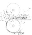
Fig. 4 is the side direction perspective cross-sectional view of conveyer mechanism, and it aims at forward and backward coiled material pairing ground, the feeding by mold pressing and polymerization station;
Fig. 5 is along the mold pressing of 5-5 line among Fig. 4 and the front cross-sectional view of polymerization station;
Fig. 6 is the eyeglass packing circuit fragment perspective that substitutes; And
Fig. 7 is its adjacent vessel of composite sheet material taken transverse and a mold cavity cross-sectional view partly among Fig. 6.
The detailed description of most preferred embodiment
Now please refer to accompanying drawing, Fig. 1 is the best eyeglass production proposing of the present invention and the rough schematic view of packaging process.Say that generally this process realizes that by first and second coiled materials 10 and 12 correspondingly are set these coiled materials preferably produce the form of reel 14 and 16, coiled material 10 and 12 are correspondingly simultaneously by these reels distributions.Then, every volume coiled material 10 and 12 individually stands the vacuum forming operation, so that, for example be on the coiled material 12 in 15, correspondingly form back, front mold chamber 18 and 20 thereon.Can be on vacuum forming chamber 18 and 20, for example be on the coiled material 12 in 22, adopt the converted steel instrument additionally to carry out secondary pressure-sizing operation to obtain to require the ground surface profile.As previously mentioned, these profiles can be substantially with same with illustrated profile phase shown in ' 875 patents, and they reappear in herein Fig. 3 A and 3B.Like this, as in ' 875 patents, in back, front mold chamber 18 and 20, edge and ring-type microgroove 52 and 47 have correspondingly been formed, they lean on distortion relatively mutually, to form the lens edge of having revised, also regulate (hereinafter will be illustrated) simultaneously for the contraction of polymerization stage list polymers.
In addition, as in ' 875 patents, preferably comprise the storage tank of establishing in 59, they be positioned at the edge of pairing and ring-type microgroove contiguous radially outside, be used for accepting herein and storing unnecessary lens materials, as seen, according to the mould centralizer that whether is provided with other by Fig. 3 B, tapered sidewalls 24 and 44 can be set selectively, and the example will be described hereinafter.If be provided with other mould centralizer, then tapered sidewalls 24 and 44 can be arranged.
Should point out also can adopt other the method that on coiled material 10 and 12, forms mold cavity 18 and 20.For example, can adopt injection moulding operation on the tinuous production make chamber 18 and 20 and coiled material 10 and 12 form simultaneously.Also have, the material that may make coiled material 10 and 12 comprises those materials that exemplify in above ' 875 patents.
Back, front mold chamber 18 and 20 be respectively after the moulding, as on station 26, the liquid list polymers 21 of measured quantity is distributed in each front mold chamber 20 in the coiled material 12.Then,, back, preceding coiled material 10 and 12 are correspondingly fitted together as on 28, so that as on 30, mold pressing and curing eyeglass between the mold cavity of pairing.
Certainly, the back, when preceding coiled material 10 and 12 fits together, their mold cavity 18 and 20 must be arranged in the engagement that centers accurately and match.For this reason, each coiled material 10 and 12 can transport (Fig. 4) by conveyer belt 27 and 29 respectively, each conveyer belt correspondingly comprises some pivots are rotationally connected, coiled material cradle 31 and 33, cushion block 33 has depression 49 in order to supporting cavity 20, and cushion block 31 has hole 45 so that ultraviolet luminous energy passes through thus, solidifies single polymers 21.Can see, with 27 and 29 mobile be synchronous so that transport coiled material 10 and 12, make mold cavity 18 and 20 be in described centering, in the mating engagement.
Though conveyer belt 27 and 29 can play feeding and aim at coiled material 10 and 12, but additional coiled material feeding/alignment device can be set also, the track feed mechanism (not shown) that for example has rotating sprocket, sprocket engagement is respectively along each coiled material 10 and 12 relative sides, the hole 23 and 25 (Fig. 2) that longitudinal separation ground forms.Alternatively or additionally, each coiled material 10 and 12 can correspondingly be provided with the nested sidewall 24 and 44 of Fig. 3 B, they are also as the centralizer in above-mentioned ' 875 patents.
As more fully illustrating in ' 875 patents, in cure stage, must regulate, to prevent in the casting eyeglass, forming bubble, surface void and other defective to the contraction of single polymers.This be by, being positioned over single polymers between mold cavity 18 and 20 when solidifying, pairing half module tool is exerted pressure, lentamente mold cavity 18 and 20 is solved facing to fitting together mutually.In the mold cavity profile of Fig. 3 A and 3B, the cold flow distortion that this relates to edge 52 and ring 47 by adopting the clamping device illustrated in fig. 12 of ' 875 patents, is resolved by the half module tool in ' 875 patents.For the purpose of the present invention, please note Fig. 5, showed among the figure that loads a transfer roller sub-assembly 35, it comprises the transfer roller 37 and 39 that place a pair of lateral separation, when being with 27 to move through sub-assembly 35, crossing being with on 27 opposite side edges 31 ' vicinity and rotates. Transfer roller 37 and 39 have load 39 ', it with 27 opposite side edge 31 ' contiguous place conveyer belt 27 is applied the downward force with predetermined value.Also be provided with supporting platen 41, be with 29 when mobile thereon, because the effect of platen 41, to being with 29 to apply reaction force FR, in single polymers 21 cure stage, because the acting in conjunction of sub-assembly 35 and platen 41, thereby applied the mold cavity 18 and 20 desired power that presses together.As described in the 8th row in ' 875 patents, if forward and backward mold cavity is made of polypropylene and PVC respectively, then clamping force is preferably the 20-40 pound.
In Fig. 5, curing is subjected to a pair of ultraviolet lamp 43 effects, this makes ultraviolet shine by being formed at the hole 45 of longitudinal separation on the cradle 31 in 27 to lamp, and other solidification equipment (as heater) also can use to substitute or auxiliary as ultraviolet.It is to be noted that coiled material 10 and 12 can correspondingly comprise the row of the laterally spaced mold cavity 18 of any amount and 20, and cradle 31 and 33 also comprises the laterally spaced hole 45 of respective numbers and caves in 49 correspondingly to place mold cavity 18 and 20.
Refer again to Fig. 1, single polymers after station 30 solidifies, coiled material 10 and 12 as be separated 32, the eyeglass 34 of casting is taken out from their corresponding mold cavities by proper device herein.Though not expression can adopt final curing and inspection further to process to casting eyeglass 34.After casting eyeglass 34 spued from mold cavity, coiled material 12 (and/or coiled material 10) correspondingly stood secondary Vacuum shaping and pressure-sizing processing as on 36 and 38, form some lens containers 40, is used for casting eyeglass 34 is positioned over wherein.Should point out that lens containers 40 is greater than mold cavity 18 and 20, so that be contained in during the aquation of carrying out after the pressure-sizing operation on 38, as the eyeglass of the expansion that on station 42, forms.After casting eyeglass 34 complete hydrated, in container 40, add an amount of eyeglass and preserve fluid (as salt solution), the periphery of cladding material (as platinum) volume 46 sealed packages, the eyeglass that after this has or do not have further external packing can be transported.As needs, can carry out cutting technique (not shown) subsequently so that cut apart the container 40 ' that is covered with.
In Fig. 6 and 7, showed the type that the is packaged into line map that substitutes, wherein taken shape on the coiled material 12 to container 40 and mold cavity 20 lateral separations.In this embodiment, the perforated tape 50 of longitudinal extension is formed between container 40 and the chamber 20, subsequently as they can be drawn back or cut (or adopting other appropriate device) on 54, to form the container band 12 ' that separates.
Claims (23)
1. the method for the some concavo-convex eyeglasses of mold pressing (34), it comprises the steps:
(a) relation that goes up with longitudinal separation at first and second coiled materials (10,12) respectively forms back, preceding lens mold chamber (18,20);
(b) curable lens material (21) with measured quantity is distributed in each described front mold chamber (20);
(c) first and second coiled materials (10,12) are aimed at and moved together;
(d) solidify lens materials (21); And
(e) separately, water each eyeglass (34) between back, the preceding lens mold chamber (18,20) that casts from pairing so that spue with described first and second coiled materials (10,12),
It is characterized in that, at step (c), back, the preceding lens mold chamber (18 of aligning, 20) move into the mutual mating engagement state that centers successively, at step (d), during curing, a clamping force is applied on the pairing coiled material (10,12) of moulding, but also comprises following additional step:
(f) at least at the middle some packing containers of moulding (40) of one of described first and second coiled materials (10,12), described casting eyeglass is positioned over wherein so that transport; With
(g) on each described container (40), apply seal closure (40 ').
2. method as claimed in claim 1 is characterized in that, in step (f), described packing container (40) is formed at and replaces one of described back, preceding lens mold chamber (18,20) of described first and second coiled materials (10,12) at least.
3. method as claimed in claim 1 also comprises the steps: to distribute the lens hydrated fluid therein in that described container (40) is applied described seal closure (40 ') before.
4. method as claimed in claim 1 is characterized in that, uses vacuum forming machine in step (a).
5. method as claimed in claim 4 is characterized in that, uses smoothing press after described vacuum forming machine.
6. method as claimed in claim 1 is characterized in that, described coiled material (10,12) and lens mold chamber (18,20) are simultaneously by the moulding of injection mould compression technology.
7. method as claimed in claim 1 is characterized in that, described container (40) is to adopt the vacuum forming machine moulding.
8. the method for the some concavo-convex eyeglasses of mold pressing (34), it comprises the steps:
(a) first and second coiled materials (10,12) are set;
(b) relation that goes up with longitudinal separation at described first and second coiled materials (10,12) respectively forms back, the preceding lens mold chamber (18,20) that can aim at;
(c) curable lens material (21) with measured quantity is distributed in each described front mold chamber (20);
(d) first and second coiled materials (10,12) are aimed at and moved together;
(e) solidify lens materials (21); And
(f) separately, water each eyeglass (34) between back, the preceding lens mold chamber (18,20) that casts from pairing so that spue with described first and second coiled materials (10,12),
It is characterized in that, first and second coiled materials (10,12) behind the aligning on, preceding lens mold chamber (18,20) move into the state that is meshing with each other that centers successively, during curing, after the pairing, preceding lens mold chamber (18,20) move together by a clamping device (30), this clamping device comprises supporting platen (41) and loads transfer roller sub-assembly (37), described second coiled material (12) is gone up guiding at described supporting platen (41) and is passed through, and described loading transfer roller sub-assembly (37) applies a power F towards described second coiled material (12) to described first coiled material (10), described supporting platen (41) applies a reaction force FR towards described first coiled material (10) to described second coiled material (12) simultaneously, thereby after described pairing, before lens mold chamber (18,20) toward each other mobile.
9. method as claimed in claim 8 is characterized in that, in step (d), described first and second coiled materials (10,12) are to be moved to together by first and second conveyer belts (27,29), described first and second conveyer belts mesh and move described first and second coiled materials (10,12) respectively.
10. method as claimed in claim 9, it is characterized in that, each described front mold chamber (20) comprises respectively and described pairing back cavity (18) opposed outer surface, and described second conveyer belt (29) comprises rigid element (38), they are aimed at the described outer surface in described front mold chamber (20), and conform to described outer surface at the profile that oppositely makes institute's moulding, when described second conveyer belt (29) moved described second coiled material (12), each described rigid element (38) supported a corresponding described front mold chamber (20).
11. the method as claim 10 is characterized in that, described reaction force FR is that described rigid element (38) effect by described second conveyer belt (29) is to the coiled material described pairing, moulding (10,12).
12. method as claimed in claim 9, it is characterized in that, described second conveyer belt (29) comprises the cradle (33) of some pivot rotation-coupled, each cushion block has a depression (49) at least, described depression (49) is aimed at described front mold chamber (20), when described second conveyer belt (29) moved described second coiled material (12), described front mold chamber (20) was arranged in corresponding described depression (49), and by its supporting.
13. method as claimed in claim 9, it is characterized in that, described first conveyer belt (27) comprises the cradle (31) of some pivot rotation-coupled, each cushion block has a hole at least, when described first conveyer belt (27) moved described first coiled material (10), described back mold cavity (18) was aimed in described hole.
14. the method as claim 13 is characterized in that, solidification is to point to by the hole on the described cradle (31).
15. the method as claim 14 is characterized in that, solidification is undertaken by the ultraviolet ray irradiation.
16. the equipment of the some concavo-convex eyeglasses of mold pressing (34), described equipment comprises:
(a) respectively in last back, the preceding lens mold chamber (18,20) that forms with the relation of longitudinal separation of first and second coiled materials (10,12)
(b) be used for the curable lens material (21) of measured quantity is distributed in the device in each described front mold chamber (20) of described second coiled material (12);
(c) be used for first and second coiled materials (10,12) are moved together the device (27,29) that described back, preceding lens mold chamber (18,20) are aimed at
(d) be used to solidify the device of distributing the described curable lens material (21) between back, the preceding lens mold chamber (18,20) that described pairing is aimed at;
(e) be used for first and second coiled materials described pairing, moulding (10,12) are applied clamping force, described clamping device (30) can turn round in case with described pairing back, preceding lens mold chamber (18,20) toward each other mobile device (30); And
(f) be used for separately described first and second coiled materials (10,12), so that expose the device (32) that waters each eyeglass (34) between back, the preceding lens mold chamber (18,20) that casts from pairing,
It is characterized in that, device (c), make curable lens material (21) with distribution described measured quantity therebetween after, preceding lens mold chamber (18,20) move into the mutual mating engagement state that centers successively, described coiled material mobile device comprises first and second conveyer belts (27,29), they transport described first and second coiled materials (10 respectively, 12), wherein each described front mold chamber (20) comprises respectively and described pairing back cavity (18) opposed outer surface, and described second conveyer belt (29) comprises rigid element (38), they are aimed at the described outer surface in described front mold chamber (20), and conform to described outer surface at the profile that oppositely makes institute's moulding, when described second conveyer belt (29) moved described second coiled material (12), each described rigid element (38) supported a corresponding described front mold chamber (20).
17. the equipment as claim 16 is characterized in that, described clamping component of force is that described rigid element (38) effect by described second conveyer belt (29) is to the coiled material described pairing, moulding (10,12).
18. equipment as claim 16, it is characterized in that, described second conveyer belt (29) comprises the cradle (33) of some pivot rotation-coupled, each cushion block has a depression (49) at least, described depression (49) is aimed at described front mold chamber (20), thereby when described second conveyer belt (29) moved described second coiled material (12), described front mold chamber (20) was arranged in corresponding described depression (49), and by its supporting.
19. equipment as claim 16, it is characterized in that, described first conveyer belt (27) comprises the cradle (31) of some pivot rotation-coupled, each cushion block has a hole at least, when described first conveyer belt (27) moved described first coiled material (10), described back mold cavity (18) was aimed in described hole.
20. the equipment as claim 19 is characterized in that, solidification equipment is to point to by the hole on the described cradle (31).
21. the equipment as claim 20 is characterized in that, described solidification equipment comprises ultraviolet lamp.
22. equipment as claim 16, it is characterized in that, described clamping device (30) comprises supporting platen (41) and loads transfer roller sub-assembly (37), described second conveyer belt (29) is gone up guiding at described supporting platen (41) and is passed through, and described loading transfer roller sub-assembly (37) engagement is positioned at the part of described first conveyer belt (27) of described first coiled material (10) opposite side, described loading transfer roller sub-assembly (37) can turn round, described first coiled material (10) is applied a power F towards described second coiled material (12), and described supporting platen (41) applies a reaction force FR towards described first coiled material (10) to described second coiled material (12) simultaneously, thereby when described first and second conveyer belts (27,29) move described first and second coiled materials (10 respectively, 12) time, after each described pairing, preceding lens mold chamber (18,20) applies described clamping force.
23. the equipment as claim 16 is characterized in that, described back, preceding lens mold chamber (18,20) are vacuum formings in described first and second coiled materials (10,12) respectively.
Applications Claiming Priority (2)
| Application Number | Priority Date | Filing Date | Title |
|---|---|---|---|
| US08/382,714 | 1995-02-02 | ||
| US08/382,714 US5524419A (en) | 1995-02-02 | 1995-02-02 | Method and apparatus for molding contact lenses and making their container |
Publications (2)
| Publication Number | Publication Date |
|---|---|
| CN1169692A CN1169692A (en) | 1998-01-07 |
| CN1066098C true CN1066098C (en) | 2001-05-23 |
Family
ID=23510089
Family Applications (1)
| Application Number | Title | Priority Date | Filing Date |
|---|---|---|---|
| CN96191655A Expired - Fee Related CN1066098C (en) | 1995-02-02 | 1996-01-30 | Method and apparatus for molding contact lenses and making their container |
Country Status (11)
| Country | Link |
|---|---|
| US (1) | US5524419A (en) |
| EP (1) | EP0802852B1 (en) |
| JP (1) | JPH10513129A (en) |
| CN (1) | CN1066098C (en) |
| AU (1) | AU4904096A (en) |
| CA (1) | CA2212044C (en) |
| DE (1) | DE69612545T2 (en) |
| ES (1) | ES2159355T3 (en) |
| HK (1) | HK1004126A1 (en) |
| MX (1) | MX9705869A (en) |
| WO (1) | WO1996023651A2 (en) |
Families Citing this family (61)
| Publication number | Priority date | Publication date | Assignee | Title |
|---|---|---|---|---|
| US6012471A (en) * | 1994-06-10 | 2000-01-11 | Johnson & Johnson Vision Products, Inc. | Automated method and apparatus for single sided hydration of soft contact lenses in package carriers |
| US5981618A (en) | 1994-06-10 | 1999-11-09 | Johnson & Johnson Vision Products, Inc. | Mold clamping and precure of a polymerizable hydrogel |
| US6692672B1 (en) * | 1997-06-02 | 2004-02-17 | Avery Dennison Corporation | EAS marker and method of manufacturing same |
| JPH11320571A (en) * | 1998-05-15 | 1999-11-24 | Menicon Co Ltd | Mold for eye lens, its manufacture and manufacture of the lens using the mold |
| US6082533A (en) * | 1998-12-15 | 2000-07-04 | Bausch & Lomb Incorporated | Contact lens package |
| US6207086B1 (en) | 1999-02-18 | 2001-03-27 | Johnson & Johnson Vision Care, Inc. | Method and apparatus for washing or hydration of ophthalmic devices |
| AR024246A1 (en) * | 1999-03-01 | 2002-09-25 | Johnson & Johnson Vision Care | CONTAINER FOR MEDICAL DEVICE. |
| WO2000066348A1 (en) * | 1999-04-30 | 2000-11-09 | Bausch & Lomb Incorporated | Method of manufacturing contact lenses by curing within a sealed package and package obtained |
| DE60008889T2 (en) * | 1999-09-09 | 2005-03-17 | Dairygold Technologies Ltd. | PROCESS FOR PACKAGING FOODS |
| US6368522B1 (en) * | 2000-01-03 | 2002-04-09 | Johnson & Johnson Vision Care, Inc. | Mold for forming a contact lens and method of preventing formation of small strands of contact lens material during contact lens manufacture |
| JP2001198929A (en) | 2000-01-17 | 2001-07-24 | Menicon Co Ltd | Molding mold for eyeglass or lens blank and method for producing eyeglass or lens blank using the mold |
| US6604342B1 (en) * | 2000-04-13 | 2003-08-12 | Paul Appelbaum | Method and apparatus for packaging articles in card and blister packages |
| CA2413804A1 (en) * | 2000-05-26 | 2001-12-06 | Gary Marceau | Process for the automated manufacture of spectacle lenses |
| FR2810969B1 (en) * | 2000-06-30 | 2002-11-15 | Coty Sa | ULTRA-FLAT INSERT BOX |
| NL1016789C2 (en) * | 2000-12-04 | 2002-06-05 | Magnafarma B V | Blister package. |
| US20020114543A1 (en) * | 2001-02-20 | 2002-08-22 | Murray R. Charles | Straw pierceable flexible pouch |
| US6663801B2 (en) * | 2001-04-06 | 2003-12-16 | Johnson & Johnson Vision Care, Inc. | Silicon carbide IR-emitter heating device and method for demolding lenses |
| KR100848761B1 (en) * | 2001-07-25 | 2008-07-28 | 가부시키가이샤 아사히오프티카루 | Semi-finished resin lens, and method and apparatus for producing the same |
| US20030029736A1 (en) | 2001-08-09 | 2003-02-13 | Phillips Robert Briggs | Contact lens package |
| US7086526B2 (en) | 2001-08-17 | 2006-08-08 | Clearlab International Pte Ltd. | Packaging for disposable soft contact lenses |
| CN1980582B (en) * | 2001-08-17 | 2010-12-22 | 美你康株式会社 | Packaging for disposable soft contact lenses |
| US7001138B2 (en) * | 2002-03-01 | 2006-02-21 | Johnson & Johnson Vision Care, Inc. | Split collar for mechanical arm connection |
| US20040075182A1 (en) * | 2002-04-10 | 2004-04-22 | Stephane Gobron | Stackable contact lens molds |
| US20030231922A1 (en) * | 2002-05-07 | 2003-12-18 | Kudalkar Vijay Balkrishna | Arrangement for making textured multi film solid cleanser holders |
| US20040004008A1 (en) * | 2002-06-26 | 2004-01-08 | Peck James M. | Contact lens packages |
| US6843043B2 (en) * | 2002-09-13 | 2005-01-18 | Alkar Rapidpak, Inc. | Web packaging pasteurization system |
| US7832552B2 (en) * | 2002-08-17 | 2010-11-16 | Menicon Co. Ltd. | Duo packaging for disposable soft contact lenses using a substrate |
| US6976347B2 (en) * | 2002-09-13 | 2005-12-20 | Alkar-Rapidpak, Inc. | Surface pasteurization method |
| US20040099971A1 (en) * | 2002-11-25 | 2004-05-27 | Technology Resource International Corporation | Lens molds and method of using the same |
| JP2007516401A (en) * | 2003-06-27 | 2007-06-21 | ボシュロム インコーポレーティッド | Packaging drying apparatus and method |
| US7459120B2 (en) * | 2003-12-04 | 2008-12-02 | Essilor International | Low pressure thermoforming of thin, optical carriers |
| GB0401542D0 (en) * | 2004-01-24 | 2004-02-25 | Jenner Simon J | A method of producing a mould |
| US20080131593A1 (en) * | 2004-01-29 | 2008-06-05 | Powell P Mark | Contact lens mold printing systems and processes |
| CA2563365A1 (en) * | 2004-04-23 | 2005-11-03 | Mystic Pharmaceuticals, Inc. | Multiple unit dose drug delivery system |
| CN100393646C (en) * | 2004-06-23 | 2008-06-11 | 亚洲光学股份有限公司 | Mould set with plural cores detachable |
| US8899547B2 (en) | 2004-11-18 | 2014-12-02 | Qspex Technologies, Inc. | Molds and method of using the same for optical lenses |
| US7114696B1 (en) | 2005-08-29 | 2006-10-03 | Qspex, Llc | Disposable molds and method of using the same |
| US20060103037A1 (en) * | 2004-11-18 | 2006-05-18 | Kai Su | Disposable molds and method of using the same |
| US20060103041A1 (en) * | 2004-11-18 | 2006-05-18 | Kai Su | Molds and method of using the same for forming plus or minus lenses |
| GB2433913B (en) | 2006-01-05 | 2007-11-28 | Bausch & Lomb | Tool |
| BRPI0706642A2 (en) * | 2006-01-18 | 2011-04-05 | Menicon Co Ltd | methods and systems for contact lens sterilization |
| GB0605238D0 (en) | 2006-03-15 | 2006-04-26 | Bausch & Lomb | Packaging foil stacking system |
| US20080072550A1 (en) * | 2006-09-01 | 2008-03-27 | Bausch & Lomb Incorporated | Heat sealing pressure monitoring system |
| US7637085B2 (en) * | 2006-10-27 | 2009-12-29 | Newman Stephen D | System and method for transferring hydrated lenses on an automated line |
| TW200823043A (en) * | 2006-11-23 | 2008-06-01 | Genius Electronic Optical Co Ltd | Method for making polysiloxane lenses |
| JP2010515541A (en) | 2007-01-09 | 2010-05-13 | ミスティック ファーマシューティカルズ, インコーポレイテッド | Nasal cartridge device |
| US9248076B2 (en) | 2007-05-16 | 2016-02-02 | Mystic Pharmaceuticals, Inc. | Dose dispensing containers |
| CA2688689C (en) | 2007-05-16 | 2015-06-30 | Mystic Pharmaceuticals, Inc. | Combination unit dose dispensing containers |
| US8683995B2 (en) | 2007-05-16 | 2014-04-01 | Mystic Pharmaceuticals, Inc. | Dose dispensing containers |
| DE102007041948A1 (en) * | 2007-09-04 | 2009-03-05 | Zahoransky Ag | Apparatus and method for producing film parts |
| CN103707452B (en) * | 2007-09-14 | 2017-05-03 | 神秘制药公司 | Deep draw container forming method |
| US7976885B2 (en) * | 2007-10-23 | 2011-07-12 | Alkar-Rapidpak-Mp Equipment, Inc. | Anti-microbial injection for web packaging pasteurization system |
| CN101842224B (en) * | 2007-10-31 | 2013-07-17 | 诺瓦提斯公司 | Additive saline dosing system and method for contact lens packaging |
| EP2866998B1 (en) * | 2012-06-28 | 2021-02-10 | Henkel AG & Co. KGaA | A method of manufacturing a composite insert |
| KR101216834B1 (en) | 2012-10-10 | 2012-12-28 | (주)주원 세미텍 | Contact lens automatic manufacture apparatus |
| TWI495921B (en) * | 2012-11-02 | 2015-08-11 | Largan Precision Co Ltd | Hybrid contact lens and its mold set and manufacturing method |
| JP6031358B2 (en) * | 2013-01-09 | 2016-11-24 | 株式会社エンプラス | Method and apparatus for manufacturing packaged molded article |
| GB2520306B (en) * | 2013-11-15 | 2015-10-21 | Rideau Machinery Inc | Improvements to rotatable forming and filling of water-soluble pouches |
| EP3028774A1 (en) * | 2014-12-03 | 2016-06-08 | MULTIVAC Sepp Haggenmüller SE & Co. KG | Packaging system including a deep draw packaging machine |
| EP3551433B1 (en) * | 2016-12-08 | 2023-05-10 | Alcon Inc. | Apparatus for sealing an ophthalmic lens package |
| TW202142576A (en) | 2020-01-27 | 2021-11-16 | 新加坡商科萊博新加坡私人有限公司 | Actinically-crosslinkable polysiloxane-polyglycerol block copolymers and methods of making and use thereof |
Citations (2)
| Publication number | Priority date | Publication date | Assignee | Title |
|---|---|---|---|---|
| GB2040213A (en) * | 1979-01-15 | 1980-08-28 | American Optical Corp | Method and apparatus for making plastics lenses |
| US4271875A (en) * | 1978-09-21 | 1981-06-09 | Philip Meshberg | Dispenser adapted for fast pressure filling |
Family Cites Families (15)
| Publication number | Priority date | Publication date | Assignee | Title |
|---|---|---|---|---|
| US2663130A (en) * | 1946-12-26 | 1953-12-22 | American Cyanamid Co | Apparatus for producing symmetrical generally ellipsoidal capsules |
| US2700939A (en) * | 1952-07-16 | 1955-02-01 | Liston Sol | Automatic means for the making and baking of bakery products |
| US3871803A (en) * | 1971-12-21 | 1975-03-18 | Beattie Dev Company | Apparatus for producing an optical molding plaque |
| US4129628A (en) * | 1976-07-19 | 1978-12-12 | Rca Corporation | Method of making a thermoplastic lens by vacuum forming |
| GB2040214B (en) * | 1979-01-10 | 1983-01-06 | Taylor D | Method of producing moulded articles |
| US4279401A (en) * | 1980-05-30 | 1981-07-21 | American Optical Corporation | Apparatus and method for making cast ophthalmic lenses |
| GB8507007D0 (en) * | 1985-03-19 | 1985-04-24 | Coopervision Optics | Casting lenses |
| GB8601967D0 (en) * | 1986-01-28 | 1986-03-05 | Coopervision Optics | Manufacturing contact lenses |
| US4721453A (en) * | 1986-03-05 | 1988-01-26 | Gte Communication Systems Corporation | Apparatus for encapsulating semiconductors |
| US4865779A (en) * | 1987-12-15 | 1989-09-12 | Minnesota Mining And Manufacturing Company | Lens molding apparatus and method |
| FR2638391B1 (en) * | 1988-10-27 | 1991-01-25 | Essilor Int | PROCESS FOR FORMING AN OPHTHALMIC LENS FROM A PALLET OF SYNTHETIC MATERIAL |
| GB2226272B (en) * | 1988-11-02 | 1993-01-13 | Nat Res Dev | Contact lens cast moulding and packaging |
| JPH04148906A (en) * | 1990-10-12 | 1992-05-21 | Seiko Epson Corp | Molding method of plastic lens |
| US5271875A (en) * | 1991-09-12 | 1993-12-21 | Bausch & Lomb Incorporated | Method for molding lenses |
| US5316700A (en) * | 1992-11-02 | 1994-05-31 | Wesley-Jessen Corporation | Method and apparatus for removing excess lens forming material |
-
1995
- 1995-02-02 US US08/382,714 patent/US5524419A/en not_active Expired - Fee Related
-
1996
- 1996-01-30 AU AU49040/96A patent/AU4904096A/en not_active Abandoned
- 1996-01-30 CN CN96191655A patent/CN1066098C/en not_active Expired - Fee Related
- 1996-01-30 CA CA002212044A patent/CA2212044C/en not_active Expired - Fee Related
- 1996-01-30 JP JP8523628A patent/JPH10513129A/en active Pending
- 1996-01-30 MX MX9705869A patent/MX9705869A/en unknown
- 1996-01-30 DE DE69612545T patent/DE69612545T2/en not_active Expired - Fee Related
- 1996-01-30 EP EP96905224A patent/EP0802852B1/en not_active Expired - Lifetime
- 1996-01-30 WO PCT/US1996/001026 patent/WO1996023651A2/en active IP Right Grant
- 1996-01-30 ES ES96905224T patent/ES2159355T3/en not_active Expired - Lifetime
-
1998
- 1998-04-24 HK HK98103483A patent/HK1004126A1/en not_active IP Right Cessation
Patent Citations (2)
| Publication number | Priority date | Publication date | Assignee | Title |
|---|---|---|---|---|
| US4271875A (en) * | 1978-09-21 | 1981-06-09 | Philip Meshberg | Dispenser adapted for fast pressure filling |
| GB2040213A (en) * | 1979-01-15 | 1980-08-28 | American Optical Corp | Method and apparatus for making plastics lenses |
Also Published As
| Publication number | Publication date |
|---|---|
| JPH10513129A (en) | 1998-12-15 |
| MX9705869A (en) | 1997-12-31 |
| EP0802852A2 (en) | 1997-10-29 |
| EP0802852B1 (en) | 2001-04-18 |
| ES2159355T3 (en) | 2001-10-01 |
| CA2212044C (en) | 2000-08-22 |
| DE69612545D1 (en) | 2001-05-23 |
| WO1996023651A2 (en) | 1996-08-08 |
| US5524419A (en) | 1996-06-11 |
| HK1004126A1 (en) | 1998-11-20 |
| AU4904096A (en) | 1996-08-21 |
| DE69612545T2 (en) | 2001-08-30 |
| CN1169692A (en) | 1998-01-07 |
| WO1996023651A3 (en) | 1996-10-24 |
| CA2212044A1 (en) | 1996-08-08 |
Similar Documents
| Publication | Publication Date | Title |
|---|---|---|
| CN1066098C (en) | Method and apparatus for molding contact lenses and making their container | |
| EP0691195B1 (en) | Contact lens production line pallet system | |
| EP0686487B1 (en) | Method and apparatus for demolding ophthalmic contact lenses | |
| EP0788871B1 (en) | Rotational indexing base curve deposition array | |
| US6315929B1 (en) | Mold assembly for forming ophthalmic lens, method of producing the same, and method of producing ophthalmic lens using the mold assembly | |
| US7479247B2 (en) | Method and apparatus for creating sacrificial patterns and cast parts | |
| MXPA97000219A (en) | Provision with rotating orientation for the deposition in b curves | |
| US20060202367A1 (en) | Multi stage ophthalmic lens demold | |
| CN101360596B (en) | Improvements in or relating to forming apparatus | |
| CN110023067A (en) | The method for manufacturing haptic lens | |
| US6453650B1 (en) | Machine for the fabrication of containers with consumable content | |
| KR20060092992A (en) | Multistage ophthalmic lens demold | |
| CN206493592U (en) | One kind realizes the continuous continual resin solidification process units of 3D printing | |
| EP1222068B1 (en) | Device for the production of disposable lenses | |
| GB2358607A (en) | Toric lens manufacture | |
| JPH02120008A (en) | Manufacture of molded sheet | |
| CN106476268A (en) | One kind realizes 3D printing continuously continual resin solidification process units and method | |
| JPS63317327A (en) | Manufacture of non-metallic tire chain |
Legal Events
| Date | Code | Title | Description |
|---|---|---|---|
| C06 | Publication | ||
| PB01 | Publication | ||
| C10 | Entry into substantive examination | ||
| SE01 | Entry into force of request for substantive examination | ||
| C14 | Grant of patent or utility model | ||
| GR01 | Patent grant | ||
| C19 | Lapse of patent right due to non-payment of the annual fee | ||
| CF01 | Termination of patent right due to non-payment of annual fee |