CN103052844A - LED lighting module and lighting lamp using same - Google Patents
LED lighting module and lighting lamp using same Download PDFInfo
- Publication number
- CN103052844A CN103052844A CN201180026047XA CN201180026047A CN103052844A CN 103052844 A CN103052844 A CN 103052844A CN 201180026047X A CN201180026047X A CN 201180026047XA CN 201180026047 A CN201180026047 A CN 201180026047A CN 103052844 A CN103052844 A CN 103052844A
- Authority
- CN
- China
- Prior art keywords
- module
- led
- mentioned
- lighting module
- led lighting
- Prior art date
- Legal status (The legal status is an assumption and is not a legal conclusion. Google has not performed a legal analysis and makes no representation as to the accuracy of the status listed.)
- Granted
Links
Images


Classifications
-
- F—MECHANICAL ENGINEERING; LIGHTING; HEATING; WEAPONS; BLASTING
- F21—LIGHTING
- F21V—FUNCTIONAL FEATURES OR DETAILS OF LIGHTING DEVICES OR SYSTEMS THEREOF; STRUCTURAL COMBINATIONS OF LIGHTING DEVICES WITH OTHER ARTICLES, NOT OTHERWISE PROVIDED FOR
- F21V17/00—Fastening of component parts of lighting devices, e.g. shades, globes, refractors, reflectors, filters, screens, grids or protective cages
-
- F—MECHANICAL ENGINEERING; LIGHTING; HEATING; WEAPONS; BLASTING
- F21—LIGHTING
- F21K—NON-ELECTRIC LIGHT SOURCES USING LUMINESCENCE; LIGHT SOURCES USING ELECTROCHEMILUMINESCENCE; LIGHT SOURCES USING CHARGES OF COMBUSTIBLE MATERIAL; LIGHT SOURCES USING SEMICONDUCTOR DEVICES AS LIGHT-GENERATING ELEMENTS; LIGHT SOURCES NOT OTHERWISE PROVIDED FOR
- F21K9/00—Light sources using semiconductor devices as light-generating elements, e.g. using light-emitting diodes [LED] or lasers
- F21K9/20—Light sources comprising attachment means
- F21K9/23—Retrofit light sources for lighting devices with a single fitting for each light source, e.g. for substitution of incandescent lamps with bayonet or threaded fittings
-
- F—MECHANICAL ENGINEERING; LIGHTING; HEATING; WEAPONS; BLASTING
- F21—LIGHTING
- F21V—FUNCTIONAL FEATURES OR DETAILS OF LIGHTING DEVICES OR SYSTEMS THEREOF; STRUCTURAL COMBINATIONS OF LIGHTING DEVICES WITH OTHER ARTICLES, NOT OTHERWISE PROVIDED FOR
- F21V19/00—Fastening of light sources or lamp holders
- F21V19/001—Fastening of light sources or lamp holders the light sources being semiconductors devices, e.g. LEDs
- F21V19/003—Fastening of light source holders, e.g. of circuit boards or substrates holding light sources
-
- F—MECHANICAL ENGINEERING; LIGHTING; HEATING; WEAPONS; BLASTING
- F21—LIGHTING
- F21V—FUNCTIONAL FEATURES OR DETAILS OF LIGHTING DEVICES OR SYSTEMS THEREOF; STRUCTURAL COMBINATIONS OF LIGHTING DEVICES WITH OTHER ARTICLES, NOT OTHERWISE PROVIDED FOR
- F21V29/00—Protecting lighting devices from thermal damage; Cooling or heating arrangements specially adapted for lighting devices or systems
- F21V29/50—Cooling arrangements
- F21V29/70—Cooling arrangements characterised by passive heat-dissipating elements, e.g. heat-sinks
- F21V29/83—Cooling arrangements characterised by passive heat-dissipating elements, e.g. heat-sinks the elements having apertures, ducts or channels, e.g. heat radiation holes
-
- F—MECHANICAL ENGINEERING; LIGHTING; HEATING; WEAPONS; BLASTING
- F21—LIGHTING
- F21V—FUNCTIONAL FEATURES OR DETAILS OF LIGHTING DEVICES OR SYSTEMS THEREOF; STRUCTURAL COMBINATIONS OF LIGHTING DEVICES WITH OTHER ARTICLES, NOT OTHERWISE PROVIDED FOR
- F21V7/00—Reflectors for light sources
- F21V7/04—Optical design
-
- F—MECHANICAL ENGINEERING; LIGHTING; HEATING; WEAPONS; BLASTING
- F21—LIGHTING
- F21V—FUNCTIONAL FEATURES OR DETAILS OF LIGHTING DEVICES OR SYSTEMS THEREOF; STRUCTURAL COMBINATIONS OF LIGHTING DEVICES WITH OTHER ARTICLES, NOT OTHERWISE PROVIDED FOR
- F21V23/00—Arrangement of electric circuit elements in or on lighting devices
- F21V23/04—Arrangement of electric circuit elements in or on lighting devices the elements being switches
- F21V23/0435—Arrangement of electric circuit elements in or on lighting devices the elements being switches activated by remote control means
-
- F—MECHANICAL ENGINEERING; LIGHTING; HEATING; WEAPONS; BLASTING
- F21—LIGHTING
- F21V—FUNCTIONAL FEATURES OR DETAILS OF LIGHTING DEVICES OR SYSTEMS THEREOF; STRUCTURAL COMBINATIONS OF LIGHTING DEVICES WITH OTHER ARTICLES, NOT OTHERWISE PROVIDED FOR
- F21V23/00—Arrangement of electric circuit elements in or on lighting devices
- F21V23/04—Arrangement of electric circuit elements in or on lighting devices the elements being switches
- F21V23/0442—Arrangement of electric circuit elements in or on lighting devices the elements being switches activated by means of a sensor, e.g. motion or photodetectors
- F21V23/045—Arrangement of electric circuit elements in or on lighting devices the elements being switches activated by means of a sensor, e.g. motion or photodetectors the sensor receiving a signal from a remote controller
-
- F—MECHANICAL ENGINEERING; LIGHTING; HEATING; WEAPONS; BLASTING
- F21—LIGHTING
- F21V—FUNCTIONAL FEATURES OR DETAILS OF LIGHTING DEVICES OR SYSTEMS THEREOF; STRUCTURAL COMBINATIONS OF LIGHTING DEVICES WITH OTHER ARTICLES, NOT OTHERWISE PROVIDED FOR
- F21V23/00—Arrangement of electric circuit elements in or on lighting devices
- F21V23/04—Arrangement of electric circuit elements in or on lighting devices the elements being switches
- F21V23/0442—Arrangement of electric circuit elements in or on lighting devices the elements being switches activated by means of a sensor, e.g. motion or photodetectors
- F21V23/0464—Arrangement of electric circuit elements in or on lighting devices the elements being switches activated by means of a sensor, e.g. motion or photodetectors the sensor sensing the level of ambient illumination, e.g. dawn or dusk sensors
-
- F—MECHANICAL ENGINEERING; LIGHTING; HEATING; WEAPONS; BLASTING
- F21—LIGHTING
- F21Y—INDEXING SCHEME ASSOCIATED WITH SUBCLASSES F21K, F21L, F21S and F21V, RELATING TO THE FORM OR THE KIND OF THE LIGHT SOURCES OR OF THE COLOUR OF THE LIGHT EMITTED
- F21Y2103/00—Elongate light sources, e.g. fluorescent tubes
- F21Y2103/10—Elongate light sources, e.g. fluorescent tubes comprising a linear array of point-like light-generating elements
-
- F—MECHANICAL ENGINEERING; LIGHTING; HEATING; WEAPONS; BLASTING
- F21—LIGHTING
- F21Y—INDEXING SCHEME ASSOCIATED WITH SUBCLASSES F21K, F21L, F21S and F21V, RELATING TO THE FORM OR THE KIND OF THE LIGHT SOURCES OR OF THE COLOUR OF THE LIGHT EMITTED
- F21Y2107/00—Light sources with three-dimensionally disposed light-generating elements
- F21Y2107/30—Light sources with three-dimensionally disposed light-generating elements on the outer surface of cylindrical surfaces, e.g. rod-shaped supports having a circular or a polygonal cross section
-
- F—MECHANICAL ENGINEERING; LIGHTING; HEATING; WEAPONS; BLASTING
- F21—LIGHTING
- F21Y—INDEXING SCHEME ASSOCIATED WITH SUBCLASSES F21K, F21L, F21S and F21V, RELATING TO THE FORM OR THE KIND OF THE LIGHT SOURCES OR OF THE COLOUR OF THE LIGHT EMITTED
- F21Y2115/00—Light-generating elements of semiconductor light sources
- F21Y2115/10—Light-emitting diodes [LED]
Abstract
The present invention relates to an LED lighting module which is formed by combining components into an integrated type to achieve efficiency in light emission-light diffusion-heat dissipating operations. The present invention also relates to a lighting lamp in which a plurality of LED lighting modules are combined to enable wide light distribution, and heat generated from the lighting lamp can be convected through a plurality of vent holes formed in all side surfaces of the lamp to achieve improved illumination efficiency and lengthen the lifespan of the lamp to tens of thousands of hours.; For this, the LED lighting module of the present invention is formed by combining, into an integrated type, an LED module in which a plurality of vertical projection type and side projection type LED elements are arrayed, a light diffusion cover having blades protruded from the left and right sides thereof, and a thin heat dissipating plate, thereby obtaining a lightweight and economically advantageous lighting module. In addition, the lighting lamp using the LED lighting module according to the present invention is configured such that said plurality of LED lighting modules are mounted on a cover of a housing having a built-in power module, and a lower cover is coupled to the cover of the housing. Thus, the lighting lamp is obtained in which heat can be dissipated smoothly regardless of the direction of use, and which enables light distribution of 180 degrees.
Description
Technical field
The present invention relates to a kind of LED lighting module that light emitting diode (LED) element is used as light source and the illuminating lamp that utilizes this led module, in more detail, relate to a kind of LED lighting module of economy and use the illuminating lamp of this led module, form the polygon illuminating lamp if wherein effectively form the lighting module of [luminous-light diffusion-heat radiation] effect by being combined in the lighting module that is combined to form integrated form, by a plurality of lighting modules towards periphery 180 the degree will produce the broadness luminous intensity distribution, the flange that relies on each lighting module left and right sides to form forms a plurality of heat transmission ventilating openings at each lighting module left and right sides, form towards periphery smoothly heat loss through convection, therefore, be not subjected to the lamp user to restriction can keep optical efficiency and will extend to more than tens thousand of hours service life.
Background technology
The LED illuminating lamp has the advantage that energy efficiency is high and the life-span is long, therefore, replaces rapidly the illuminating equipment of the light sources such as existing fluorescent lamp, incandescent lamp.The LED element that is used for the LED illuminating lamp is compared with existing lighting source has that caloric value is little, power consumption is few and the advantages such as life-span length, resistance to impact.And in process of production, fluorescent lamp is different from making, and the LED element has the advantage that does not cause environmental pollution owing to do not use mercury or discharge gas.
The LED element is provided in the situation of suitable power supply supply and suitable heat abstractor, even if use more than 100,000 hours, the LED element also keeps luminance and without any damage.But the output of the light of all light sources is all along with passage of time decays gradually.Since people luminous intensity become initial light intensity 80% the time can not discover and difference, be contemplated at present about 40-50 more than thousand hours with life-span of this standard evaluation LED element.Therefore, the LED element be called as have than the life-span be the more long-life light source of fluorescent lamp that 1500 hours incandescent lamp and life-span is 10,000 hours.
Yet when increasing the drive current of LED element for the illumination light source that obtains high brightness and high-power economy, the power loss of LED element increases, and causes most of electric energy conversion to be heat, and the bonding part of LED element is in the condition of high temperature.The characteristic of LED element is, even the electric current of the LED element of flowing through is constant, when the temperature of bonding part increased, its light output and optical efficiency can reduce, and working life also shortens.Therefore, in order to improve illumination performance and working life, be necessary to discharge to greatest extent the heat that produces from the bonding part of LED element.
Usually, the LED illuminating lamp of the electric ball shape that volume and inner space are little is compared with the illuminating lamp of other shapes, and its structure is unfavorable for diverging LED element liberated heat.Therefore, in order to increase light output, illuminating lamp at electric ball shape and compact form is installed a large amount of LED elements, owing to there is the limitation of erection space and area of dissipation, therefore, not only be difficult to obtain the lighting source of high brightness, and when illuminating equipment is installed, cause the heat of lamp inside to gather easily variation and the lost of life of the light that the LED element will occur.
In addition, the common LED illuminating lamp forms luminescence unit at the LED element of the arranged in front high brightness of the heat-dissipating frame of a plurality of radiating fins formation, has made illuminating lamp on the luminescence unit for reducing dazzling milky diffuser cap is covered on.But because this mode makes the backlight of luminescence unit form narrowly to all directions, not only differences of illumination intensities is deep but also produced a large amount of light losses, reduce illuminance by dark milky diffuser cap during illumination, the service life that thermal accumlation shortens the LED element also occurs in the inside of diffuser cap.
And, along with behind the circuit board of a plurality of circuit board LED of the front of heat-dissipating frame mounting arrangements element, because erection space is defined, a large amount of LED elements can not be set, therefore, in order to obtain a lot of light quantities with the quantity of restriction, use LED element or the larger heat-dissipating frame of manufacturing model of the high brightness of high price, thereby cause the volume and weight increase of illuminating lamp will drop into the universal hard problem of more manufacturing expense existence.
Therefore, in order to substitute existing incandescent lamp and compact fluorescent lamp with the lighting environment of the LED of expansion energy-conserving and environment-protective, the heat abstractor of the lighter and high effect that is integrated without dazzling, broad luminous intensity distribution condition when must possess the optical efficiency that improves the LED illuminating lamp.
Summary of the invention
The present invention will provide a kind of LED lighting module, be included in the one side and have the led module a plurality of LED elements and that formed by planar luminous body that has of arranging on the circuit board for the attachment plug that connects power supply, form respectively the light diffuser cap of more than one flange with the top of half round post covering led module, in the left and right side, and for covering led module bottom combination, have the lower edge of inserting the light diffuser cap and be fixed in the heat sink of metal material of the periphery of light diffuser cap lower end, wherein led module, light diffusing sheet and the combination of heat sink integral body.
According to the illuminating lamp that utilizes above-mentioned lighting module of the present invention, be included in the power module housing that a side is fixed with power supply connection base with providing, with the power module that is installed on the power module enclosure interior, with the bottom that covers power module, be fixed on the housing of power module and around it, form the circular barricade that the hole is used in a plurality of attachment plugs, be fixed in the power module housing with the circular barricade of covering, form a plurality of ventilating openings around at the edge and around the lower end, form the case lid of 2 above LED lighting module insert ports in the bottom surface, with the module insert port of inserting and be fixed to case lid, the above-mentioned LED lighting module that is connected and connects power supply with attachment plug with power module, with the lamp type luminescence unit that in case lid module insert port, inserts 2 above lighting modules formation polygonized structures, when combining light-emitting units, the flange that forms at above-mentioned each LED lighting module left and right sides be in contact with one another a plurality of heat transmission ventilating openings of being respectively formed at each lighting module left and right sides composition surface and, and in above-mentioned led module bottom detachable in conjunction with and the luminescence unit of supporting combination, the bottom surface forms the bottom end cover of an above heat transmission ventilating opening.This illuminating lamp can produce backlight the reaching of 180 degree and carry out towards periphery heat loss through convection.
One embodiment of the invention, possesses the led module of arranging a plurality of LED elements on the circuit board for the attachment plug that connects power supply, being formed by planar luminous body with being provided at a side, with the top that covers led module with half round post, on the left and right side, form respectively the light diffuser cap of more than one flange, and for covering led module bottom combination, the heat sink that its periphery is inserted the lower edge of light diffuser cap and is fixed in the metal material of light diffuser cap lower end is combined as the integrated form module, is formed for the LED lighting module of the light emitting module of illuminating lamp.
In the embodiment of the invention described above, the a plurality of LED elements that are arranged in led module are arranged to make it to the top projection source, side at led module arranges the side porjection type LED element that throws to light diffuser cap one side more than, when forming according to illuminating lamp of the present invention, not only around luminescence unit, also throw a large amount of light sources to the downward direction of luminescence unit, be conducive to realize not exist 180 degree of broadness of light dead zone backlight.
In the embodiment of the invention described above, further comprise the inner face that is supported in the light diffuser cap and cover led module, the face corresponding with the light-emitting area of the LED element that is arranged in led module forms transparency window, remains the bottom surface or is reflected processing, the module reflecting plate that transparent window portion is holed in reflecting plate.This will help the light diffusion.
In the embodiment of the invention described above, preferably, the light diffuser cap is shaped with transparent or semitransparent and milky material according to lighting use, for the light source that spreads largo the LED element forms diverging lens at the interior curve face of light diffuser cap.
In the embodiment of the invention described above, preferably, be the heat dissipation ceramic of radiant energy at the outer surface plated film of heat sink with thermal power transfer, brilliant or other heat sink materials of carbon improve heat-sinking capability, illuminating lamp aspect with being identically formed light output can reduce weight and make inexpensive heat sink.
Simultaneously, preferably, above-mentioned heat sink adopts the good sheet metal of heat conductivity, side coated heat conductibility sticker at sheet metal, the another side is mounted to brilliant or other heat sink material heat radiation plates of plated film heat dissipation ceramic, carbon, it is adhered to simultaneously around the edge of light diffuser cap and below the led module inside of sealed illuminated module when making lighting module, be used for heat sink material, will be conducive to save producing cost.
According to an embodiment who utilizes the illuminating lamp of above-mentioned LED lighting module of the present invention, will provide the illuminating lamp that utilizes the LED lighting module, comprising:
One side is fixed with the power module housing that power supply connects base, with the power module that is installed on the power module enclosure interior, with the bottom that covers power module, be fixed on the housing of power module and around it, form the circular barricade that the hole is used in a plurality of attachment plugs, be fixed in the power module housing with the circular barricade of covering, form a plurality of ventilating openings around at the edge and around the lower end, form the case lid of 2 above lighting module insert ports in the bottom surface, with the module insert port of inserting and be fixed to case lid, the above-mentioned LED lighting module that is connected and connects power supply with attachment plug with power module, with the lamp type luminescence unit that in case lid module insert port, inserts 2 above LED lighting modules formation polygonized structures, when combining light-emitting units, between the flange that above-mentioned each LED lighting module left and right sides forms, be in contact with one another a plurality of heat transmission ventilating openings of being formed at respectively each lighting module left and right sides faying face and, and in above-mentioned led module bottom detachable in conjunction with and the luminescence unit of supporting combination, the bottom surface forms the bottom end cover of an above heat transmission ventilating opening.This illuminating lamp can produce backlight the reaching of 180 degree and carry out towards periphery heat loss through convection.
Among the above-mentioned embodiment according to illuminating lamp of the present invention, replace bottom end cover in the central authorities of bottom end cover the annular bottom end cover that forms the clathrate ventilating opening to be set, possess the annular LED lighting module of downward direction projection illumination light source in the inside of annular bottom end cover.Preferably, above-mentioned bottom end cover is installed in the illuminating lamp, is conducive to throw more lighting source to the downward direction of illuminating lamp.
Among the above-mentioned embodiment according to illuminating lamp of the present invention, preferably, central authorities at circular barricade further comprise the radiant heat that can cut off to come from above-mentioned illuminating lamp luminescence unit inside to circular barricade, change the thermal cut-out lid of heat dissipation direction to the side vent of above-mentioned case lid.
Among the above-mentioned embodiment according to illuminating lamp of the present invention, preferably, above-mentioned each the LED lighting module that is installed in the cylindrical luminescence unit of illuminating lamp shine the illuminating lamp side around, it is backlight that the illuminating source of the side projection shape LED element by being arranged at each LED lighting module one side produces 180 degree to the downward direction projection illumination light source of illuminating lamp.
Among the above-mentioned embodiment according to illuminating lamp of the present invention, in bottom end cover, possess the optical pickocff for the self-control lighting degree, utilize optical pickocff and can change illuminance and colour rendering according to the manipulation of remote controller.To be conducive to the use of illuminating lamp.
Among the above-mentioned embodiment according to illuminating lamp of the present invention, be convenient to exchange by the mounting or dismounting of case lid and bottom end cover when the LED lighting module reaches service life, this will be conducive to reduce discarded object, energy savings, the environment of preserving our planet.
LED lighting module according to the present invention is the integrated form light emitting module of effective formation [luminous-light diffusion-heat radiation] effect, being conducive to standardization ground makes light output and light spreads and heat-sinking capability is carried out optimized lighting module, therefore, be convenient to according to lighting use assembly illuminating lamp, have the weight that can reduce illuminating lamp, save the economic effect of manufacturing expense in a large number.
Utilize the illuminating lamp of LED lighting module of the present invention, with cylindrical shape combination a plurality of according to LED lighting module according to the present invention form 180 degree broad backlight exist hardly dazzling, carry out fast towards periphery the structure of heat loss through convection by a plurality of ventilating openings that form in the side of luminescence unit and bottom, therefore be not subjected to the lamp user to restriction can stably keep optical efficiency and life-span as the LED element of light source, have the economic effect of semi-permanent use illuminating lamp.
Utilize the illuminating lamp of LED lighting module of the present invention, have the package assembly of the most lighting modules of combination, replace easily the lighting module that reaches the life-span, can reuse housing and the part of illuminating lamp, reduce rubbish and contribute to the environmental effect that economizes on resources.
Utilize the illuminating lamp of LED lighting module of the present invention, with dazzling less, wide luminous intensity distribution and semipermanent life-span can replace existing incandescent lamp and compact fluorescent lamp, have power saving and economize on resources and improve the effect of earth environment.
Description of drawings
Fig. 1 illustrates the according to an embodiment of the invention perspective view of LED lighting module;
Fig. 2 is the expanded view of launching to illustrate Fig. 1 structure;
Fig. 3 is the perspective view that each LED element luminance shown in Figure 1 is shown;
Fig. 4 is the perspective view that luminous behind the overlay module reflecting plate and reflective condition are shown above the illustrated whole LED elements of Fig. 1;
Fig. 5 is the part expanded view that the LED lighting module formation LED structure of the lighting lamp of 4 Fig. 1 of combination is shown;
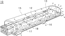
Fig. 6 illustrates the according to an embodiment of the invention perspective view of illuminating lamp;
Fig. 7 is the illuminating lamp perspective view of luminance towards periphery of exploded view 6;
Fig. 8 is illuminating lamp that Fig. 6 is shown carries out the heat loss through convection state by each ventilating opening perspective view;
Fig. 9 is illuminating lamp that Fig. 6 is shown carries out the heat loss through convection state when installing to the upper direction of socket by each ventilating opening perspective view;
Figure 10 is illuminating lamp that Fig. 6 is shown carries out the heat loss through convection state when installing to the horizontal direction of socket by each ventilating opening perspective view;
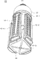
Figure 11 is the perspective view of illuminating lamp according to another embodiment of the present invention;
Figure 12 is the illuminating lamp perspective view of luminance towards periphery that Figure 11 is shown;
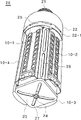
Figure 13 is illuminating lamp that Figure 11 is shown carries out the heat loss through convection state by each ventilating opening perspective view;
Figure 14 is the plane of circular barricade of power module lower end that the shielding illuminating lamp of Fig. 6 and Figure 11 is shown; And
Figure 15 illustrates the possessing in the longitdinal cross-section diagram of the circular barricade in the thermal cut-out lid cross section of the central portion of circular barricade of Figure 14.
The specific embodiment
Fig. 1 illustrates the according to an embodiment of the invention perspective view of LED lighting module, Fig. 2 is the expanded view of launching to illustrate Fig. 1 structure, Fig. 3 is the perspective view that luminance in each LED element of Fig. 1 is shown, and Fig. 4 is the perspective view that luminous behind the overlay module reflecting plate and reflective condition are shown on whole LED elements of Fig. 1.
Extremely shown in Figure 2 such as Fig. 1, LED lighting module 10 according to a preferred embodiment of the invention forms the integrated LED module, a plurality of perpendicular projection shape LED elements 12 of wherein arranging and side projection shape LED element 13, the led module 11, light diffuser cap 15 and the heat sink 19 that possess attachment plug 14 in a side are combined on the cooling circuit board, according to lighting use with module unit with the inscape optimization, make its standardization and effectively form [luminous-light diffusion-heat radiation] effect.
Below, describe structure and running according to LED lighting module of the present invention in detail.Led module 11 is configured to, a plurality of perpendicular projection shape LED elements 12 are set to be connected shape LED element 13 1 and to possess in the one side and connect power supply and form planar luminous body with the cooling circuit board of attachment plug 14 with the side, light diffuser cap 15 is configured to cover led module top and form respectively more than one flange 16 at left and right sides with half round post, heat sink 19 combinations are with the bottom that covers led module 11 and the periphery that is configured to have the lower edge of insertion light diffuser cap 15 and is fixed on light diffuser cap 15 lower ends, above-mentioned component integration combination, thus the illuminating lamp lighting module formed.
Among the embodiment of the invention described above, when led module 11 covers light diffuser cap 15, be adjacent to compactly around the interior lower end of clamping light diffuser cap 15 around the edge of led module 11, prevent that extraneous air from flowing into the inner space of light diffuser cap 15, therefore, luminescence unit can not pollute when long-term the use yet.And; heat sink 19 rely on heat conduction adhesive tape TIM TAPE adhere to led module 11 below impel be adjacent to compactly around its edge clamp light diffuser cap 15 lower ends around; guarantee that led module 11 is subject to the upper-lower seal protection, it is inner to prevent that moisture and dust from flowing into luminescence unit.Aspect electrical insulating property, keep making lighting module be subject to safe protection with outside electric insulation, also guarantee the safety to human body.
Among the embodiment of the invention described above, preferably plated film is that brilliant or other heat sink materials of heat dissipation ceramic, the carbon of radiant energy improve heat-sinking capabilities with thermal power transfer on the outer surface of the heat sink 19 of metal material, the weight that helps to reduce the heat sink material of illuminating lamp is saved manufacturing expense, forms a plurality of radiating fins and is coated with heat sink material in the above and is conducive to improve heat-sinking capability at the outer surface of heat sink 19.
Simultaneously, among the embodiment of the invention described above, the heat sink of metal material will adopt the copper that heat conductivity is outstanding, aluminium etc. are rolled into the sheet metal that sensitive paper is opened thin, at sheet metal one side coated heat conductibility sticker, the another side is mounted to the plated film heat dissipation ceramic, brilliant or other heat sink material heat radiation plates of carbon, when making lighting module, it is adhered to simultaneously around the edge of above-mentioned smooth diffuser cap and below the led module, the heat sink material that is used for sealed illuminated inside modules, with respect to radiating effect, to produce more economically LED lighting module 10 of the present invention, and be conducive to thus reduce the manufacturing cost of illuminating lamp.
Especially, LED lighting module 10 of the present invention, make in advance with the standardized module of light output unit, needs according to lighting use, be incorporated into the power module case lid assembling of illuminating lamp, fully satisfy the associativity of inscape and sealing and then can produce in a large number when manufacturing module, lighting module has efficientibility can save the illuminating lamp manufacturing expense.
Fig. 3 is the perspective view that each LED element luminance shown in Figure 1 is shown.A plurality of perpendicular projection shape LED elements 12 of arranging at led module 11 are arranged in the side projection shape LED element 13 of led module 11 1 sides to the end projection source of light diffuser cap to the top projection source of half-cylindrical light diffuser cap 15.A plurality of perpendicular projection shape LED elements 12 are luminous to the side periphery of illuminating lamp after making up a plurality of LED lighting modules formation illuminating lamps, thereby side projection shape LED element 13 is realized 180 broad degree luminous intensity distributions to the luminous light dead zone that do not exist of the downward direction of illuminating lamp.Represent the light source that throws by the arrow of dashed lines labeled in the drawings.
Especially, extremely shown in Figure 4 such as Fig. 3, LED lighting module 10 of the present invention, form in the left and right side of half-cylindrical light diffuser cap 15 one heat radiation that not only is conducive to illuminating lamp with upper flange 16 also plays a part to reduce the light dead zone, is induced to the end of flange to the light source of light diffuser cap 15 left and right sides projection by the internal reflections in the light diffuser cap 15.Therefore, make up a plurality of LED lighting modules 10 with cylindrical shape and form illuminating lamp, the flange 16 that forms at LED lighting module 10 left and right sides be in contact with one another and flange 16 form respectively up and down ventilating opening, and the offside reflection photoinduction of light diffuser cap 15 is around each ventilating opening and flange 16.Therefore, although have a plurality of ventilating openings in each side of illuminating lamp, there is not on the whole the light dead zone at luminescence unit, can obtains the advantageous effects that light source spreads largo.
Fig. 4 is the perspective view that luminous behind the overlay module reflecting plate and reflective condition are shown above the illustrated whole LED elements of Fig. 1, in order further to increase the light diffusion of the illustrated LED lighting module 10 of Fig. 3, the module reflecting plate is covered to above the led module 11.
Among the embodiment of the invention described above, module reflecting plate 17 is supported on the two ends of half-cylindrical light diffuser cap 15 and covers led module 11.The face corresponding with the illuminator of the LED element 12 that is arranged in above-mentioned led module 11 forms transparency window, remains the bottom surface or is reflected processing, and above-mentioned transparent window portion has formed module reflecting plate 17 after being holed into boring 18.When the light source of each LED element 12 projection throws to the inside of half-cylindrical light diffuser cap 15 by boring 18, part light direct irradiation, the process that the lensing of part light by half-cylindrical curved surface reflects by the outstanding module reflecting plate 17 of reflecting effect after the flexure plane reflection again reaches light loss and minimizes, obtain stable light diffusion effect, therefore, at LED lighting module 10 suitable modules reflecting plate 17 preferably.
Among the embodiment of the invention described above, light diffuser cap 15 is made with transparent or semitransparent and milky material according to lighting use.For spreading largo LED element 12,13 light source, also will reduce light loss at a plurality of formation of the inner face of light diffuser cap 15 diverging lens as zigzag lens, lens pillar or concavees lens and help to obtain stable light diffusion effect.
Fig. 5 is the part expanded view that LED lighting module that 4 Fig. 1 of combination are shown forms the LED structure of the lighting lamp, and Fig. 6 illustrates the according to an embodiment of the invention perspective view of illuminating lamp, and Fig. 7 is the illuminating lamp perspective view of luminance towards periphery of exploded view 6.
Extremely shown in Figure 6 such as Fig. 5, utilization is according to the illuminating lamp 20 of the LED lighting module of the embodiment of the invention, has the power module housing 22 that the power supply that is fixed in a side connects base 21 by combination, above-mentioned Fig. 1 is to 4 LED lighting modules 10 shown in Figure 4,10-1~10-4, and lower end housing 23 and form one.
Below, describe the formation and the running that utilize according to the illuminating lamp 20 of LED lighting module of the present invention in detail.This illuminating lamp comprises, be configured to the one side and be fixed with the power module housing 22 that power supply connects base, power module is installed on power module housing 22 inside, be configured to cover the bottom of power module, be fixed on the housing 22 of power module and around it, form the circular barricade 28 that the hole is used in a plurality of attachment plugs, be configured to cover circular barricade 28 and be fixed in power module housing 22, form a plurality of ventilating openings 25 around at the edge and around the lower end, form 2 case lid 22-1 with the upper module insert port in the bottom surface, insert and be fixed to the module insert port of case lid 22-1, be connected and connect above-mentioned Fig. 1 of power supply with power module with attachment plug to LED lighting module 10 shown in Figure 4,10-1~10-4, with 2 above LED lighting modules 10 of insertion in case lid 22-1 module insert port, 10-1~10-4 forms the lamp type luminescence unit of polygonized structure, when combining light-emitting units, at above-mentioned each LED lighting module 10, be in contact with one another a plurality of heat transmission ventilating openings 26 that are formed at respectively each lighting module left and right sides faying face between the flange that 10-1~10-4 left and right sides forms, and at above-mentioned led module 10, the luminescence unit of 10-1~detachable combination in 10-4 bottom and supporting combination, the bottom surface forms the bottom end cover 23 of an above heat transmission ventilating opening 27.This illuminating lamp can produce backlight the reaching of 180 degree and carry out towards periphery heat loss through convection.
Among the embodiment of the invention described above, as shown in Figure 5, with 4 LED lighting modules 10 of cylindrical shape combination, 10-1~10-4 and with the lower end of bottom end cover 23 fastening lighting modules will formation illuminating lamp 20 shown in Figure 6 in case lid 22-1 lower end.By the flange 16 that forms at each LED lighting module 10,10-1~10-4 left and right sides at a plurality of ventilating openings 26 of the microscler one-tenth of the corner of each side lira with at the ventilating opening 25 of upper end case lid 22-1 and the ventilating opening 27 that forms at bottom end cover 23, at the inner air duct that forms of illuminating lamp, each LED lighting module 10, the radiant heat of dispersing when 10-1~10-4 is luminous will carry out rapidly heat loss through convection by each ventilating opening, keep luminous efficiency, the service life of illuminating lamp stably to extend to for a long time.Be not subjected to the illuminating lamp user to restriction, carry out the thermolysis of heat loss through convection by each ventilating opening and will do more detailed description at Fig. 8 to Figure 10.
Among the embodiment of the invention described above, Fig. 7 illustrates towards periphery luminance of illuminating lamp, in a plurality of perpendicular projection shape LED elements 12 of the internal placement of each LED lighting module 10,10-1~10-4 each side surface direction projection source to illuminating lamp 20, although each side projection shape LED element 13 does not have the special illuminator that arranges to the downward direction projection source of illuminating lamp 20 in the bottom, can obtain to form broad 180 degree illuminating effect backlight.Simultaneously, for the light source of inducing LED lighting module 10,10-1~10-4 avoids occuring shade, preferably adopt with the photodiffusion material of light diffuser cap 15 identical materials and come moulding to make bottom end cover 23.
Simultaneously, come LED lighting module 10, the 10-1~10-4 of production standard according to lighting use reasonable distribution side projection light and below projection light, select according to lighting use, can make the illuminating lamp with suitable curve backlight, thus, preferably make up a plurality of LED elements, the integrated form side projection shape LED element 13 with multiple light fan-out capability is set is installed on LED lighting module 10.
Fig. 8 is illuminating lamp that Fig. 6 is shown carries out the heat loss through convection state by each ventilating opening perspective view, Fig. 9 is illuminating lamp that Fig. 6 is shown carries out the heat loss through convection state when installing and using to the upper direction of socket by each ventilating opening perspective view, and Figure 10 is illuminating lamp horizontal direction that Fig. 6 is shown is carried out the heat loss through convection state when installing by each ventilating opening perspective view.Among the figure, inside is the air stream that empty arrow shows convection current.
Among the embodiment of the invention described above,, as existing incandescent lamp or compact fluorescent lamp, install and use illuminating lamp of the present invention in any direction and can both realize life-span of dispelling the heat smoothly and not reducing illuminating lamp to shown in Figure 10 such as Fig. 8.Illuminating lamp 20 according to the present invention in order to achieve the above object forms a plurality of ventilating openings 26 in each corner, side of luminescence unit, and also form ventilating opening 25 in the upper end case lid, and also form most ventilating openings 27 at bottom end cover, when illuminating lamp 20 is luminous because the inner air of each LED lighting module 10-1~10-4 sends out thermogenetic heating relies on the convection action that produces because of the temperature difference to be dispelled the heat away rapidly by a plurality of ventilating openings.
Therefore, according to illuminating lamp 20 of the present invention, do not use the fin of existing massive aluminium material for the heat dissipation capacity of eliminating LED lighting module 10-1~10-4, carry out heat loss through convection by a plurality of ventilating openings 25~27 after the thin and light heat sink 19 of the solar heat protection material that the dependence plated film is a small amount of changes into the radiant heat energy with heat energy, can make the light and cheap illuminating lamp that is conducive to economy.
Among the embodiment of the invention described above, when showing illuminating lamp 20 is installed in the socket of ceiling, Fig. 8 produces the state of heat loss through convection by each ventilating opening, after inner air is heated when LED lighting module 10-1~10-4 is luminous light air by ventilating opening 25 dischargings of the case lid of upper end in ambient air flow into by the ventilating opening 26 in each corner, side of illuminating lamp 20 and the ventilating opening 27 of bottom end cover, form rapidly the heat loss through convection effect, eliminate the heat dissipation problem of illuminating lamp.
Fig. 9 is illustrated in the supply socket state that carries out heat loss through convection when with upper direction illuminating lamp 20 being installed by each ventilating opening, the opposite ventilating opening 26 that forms by illuminating lamp 20 each corner, side with Fig. 8 and rely on the situation of ventilating opening 27 dischargings that convection action forms by the lamp bottom end cover at the extraneous air that the ventilating opening 25 that the lower end case lid forms flows into.
Figure 10 is identical with situation about arranging at wall surface, show in supply socket the state of the heat loss through convection that is undertaken by each ventilating opening when illuminating lamp 20 horizontal directions are installed, the extraneous air that each below ventilating opening of the ventilating opening 25 that the ventilating opening 27 that the ventilating opening 26 that each corner, side by illuminating lamp 20 forms and bottom end cover form and case lid form flows into is by the situation of each ventilating opening discharging of upper end.
Figure 11 is the perspective view of illuminating lamp according to another embodiment of the present invention, and Figure 12 is the illuminating lamp perspective view of luminance towards periphery that Figure 11 is shown, and Figure 13 is illuminating lamp that Figure 11 is shown carries out the heat loss through convection state by each ventilating opening perspective view.
The illuminating lamp that utilizes the LED lighting module 30 according to another embodiment of the present invention, connect base 21 such as Figure 11 to power supply shown in Figure 13 and be fixed in a side power module housing 22, above-mentioned Fig. 1 to Fig. 4 illustrated 4 each LED lighting module 10,10-1~10-4 is combined into one with the bottom end cover 31 that possesses the ring illumination module and has formed illuminating lamp.
Among another embodiment of the invention described above, Figure 11 is identical substantially to the formation of illuminating lamp 20 shown in Figure 10 and effect with above-mentioned Fig. 5 to illuminating lamp 30 shown in Figure 13, difference is the bottom end cover 23 that the bottom end cover 31 that possesses the ring illumination module of lighting function has replaced not possessing the above-mentioned illuminating lamp 20 of self-lighting function, improves energetically the illumination light that illuminating lamp 30 throws downwards.
Therefore, omit above-mentioned and the formation of illuminating lamp 20 and the detailed description of effect repeating part, be elaborated to being installed in to formation and the effect of the bottom end cover that possesses the ring illumination module 31 of the lower end of 5 luminous illuminating lamps 30.Form the clathrate ventilating opening in the central authorities of bottom end cover, flow into extraneous air or inner hot gas is discharged according to the user of illuminating lamp 30 to guiding.The annular LED lighting module that possesses downward direction projection illumination light source in annular bottom end cover inside, and 4 LED lighting module 10-1 that possess at side surface light emitting unit ~ 10-4 forms and is in harmonious proportion the illuminating lamp 30 that forms as shown in figure 12 180 degree uniform backlights.
Among the embodiment of the invention described above, above-mentioned annular LED lighting module, central portion at the disc cooling circuit board is being arranged a plurality of LED elements with the circuit board of annular boring, the annular bottom end cover covers above-mentioned annular circuit board, the electric wire supply power supply that the tail end of the led module by above-mentioned LED lighting module 10-1 ~ 10-4 connects, the luminous below of shining illuminating lamp 30 of LED lighting module.
Among the embodiment of the invention described above, Figure 13 illustrates the heat loss through convection state of illuminating lamp 30, become respectively inflow entrance or the inner air outlet of extraneous air according to the user of illuminating lamp 30 to different each ventilating opening 25~27, according to the user to the heat loss through convection effect identical with the situation of above-mentioned Fig. 8 to Figure 10.
Figure 14 is the plane of circular barricade of power module lower end that the shielding illuminating lamp of Fig. 6 and Figure 11 is shown, and Figure 15 illustrates the possessing in the longitdinal cross-section diagram of the circular barricade in the thermal cut-out lid cross section of the central portion of circular barricade of Figure 14.
In the embodiments of the invention shown in Fig. 5 to Figure 13; built-in and be fixed in the bottom of power module housing 22 around power module; above-mentioned power module is carried out electric shield and from outside induced voltage the central authorities of the circular barricade 28 of protection power source module, preferably further setting can be blocked the radiant heat that comes to circular barricade 28 from illuminating lamp 20,30 luminescence unit inside, change rapidly the thermal resistent cover of heat dissipation direction to the side vent of case lid 22-1.
Among the embodiment of the invention described above, the attachment plug that is connected to expediently each lighting module 10-1~10-4 for the attachment plug that will be connected to power module each attachment plug hole 29 by circular barricade 28 is provided with in circular barricade 28 illustrated attachment plug holes 29.
In the embodiments of the invention shown in Fig. 5 to Figure 13, in above-mentioned bottom end cover 23,31, possess for the optical pickocff 24 of controlling illuminance according to outside light quantity self-control lighting degree.Rely on optical pickocff to detect light quantity, automatically regulate illuminance by power module and be, belong to general known circuit engineering, therefore omit detailed explanation.And, above-mentioned optical pickocff 24 also uses as the collection of letters sensor of general remote controller, the user handled remote controller and can manually change illuminance and colour rendering this moment, be conducive to improve the operability of illuminating lamp of the present invention, and this also is the explanation that known circuit engineering omits detailed drive circuit.
In the embodiments of the invention of above-mentioned explanation, be installed in 20,30 side periphery of each LED lighting module 10, the 10-1~10-4 irradiating illumination lamp of illuminating lamp 20,30 cylindrical luminescence unit, thereby also form the backlight of 180 degree to illuminating lamp 20,30 downward direction projection illumination light source by feat of the illuminating source of the side projection shape LED element 13 that is arranged at each LED lighting module 10,10-1~10-4, therefore do not have light dead zone, of great use at luminescence unit.
In the embodiments of the invention of above-mentioned explanation, above-mentioned LED lighting module 10, when 10-1~10-4 reaches service life, be convenient to exchange by above-mentioned case lid 22-1 and bottom end cover 23,31 mounting or dismounting, the illuminating lamp housing and the parts that use as main body in illuminating lamp 20 of the present invention, 30 can semi-permanently re-use, can reduce discarded object and economize on resources, very practical.
In claim scope of the present invention; do not break away under the prerequisite of main idea of right request; the personnel that the art has a general knowledge can carry out numerous variations and implement, and therefore technical protection scope of the present invention is not limited to above-mentioned specific preferred embodiment.
The industrial utilization possibility
The present invention is the compact LED illuminating lamp that can replace existing incandescent lamp and fluorescent lamp, the semiconductor LED element of the harmful substance such as not mercurous is used as illuminator, have breakthrough power savings and semipermanent long-life, reduce discarded object, economize on resources, industrial can being widely used.
Claims (according to the modification of the 19th of treaty)
1. a LED lighting module is characterized in that, comprising:
Led module is configured to have a plurality of LED elements and is formed by planar luminous body, and described LED element is arranged on the one side and possesses circuit board for the attachment plug that connects power supply;
The light diffuser cap is configured to cover with half round post the top of above-mentioned led module, and forms respectively more than one flange in the left and right side; And
Heat sink, it is configured to its periphery and is adjacent to the lower edge of inserting the light diffuser cap and is fixed in light diffuser cap lower end, and made by metal material for covering above-mentioned led module bottom combination, wherein, led module, light diffuser cap and the integrated combination of heat sink.
2. LED lighting module according to claim 1, it is characterized in that, be arranged to the perpendicular projection shape of the semicircle column type interior curve face projection source of above-mentioned smooth diffuser cap at a plurality of LED elements that above-mentioned led module is arranged, in side projection shape LED element from a side of above-mentioned led module to above-mentioned smooth diffuser cap bottom sides projection be set also more than one.
3. LED lighting module according to claim 1, it is characterized in that, further comprise the module reflecting plate, it is supported in the inner surface of above-mentioned smooth diffuser cap and covers above-mentioned led module, wherein the surface of the described module reflecting plate corresponding with the light-emitting area of the LED element that is arranged in above-mentioned led module forms transparency window, remain the bottom surface or be reflected processing, transparent window portion is holed in reflecting plate.
4. LED lighting module according to claim 1, it is characterized in that, above-mentioned smooth diffuser cap is made with transparent or semitransparent and milky material according to lighting use, and is that the light source that spreads largo the LED element forms diverging lens at the interior curve face of above-mentioned smooth diffuser cap.
5. LED lighting module according to claim 1, it is characterized in that, this module also be included in above-mentioned heat sink the outer surface plating be the heat dissipation ceramic of radiant energy with thermal power transfer, brilliant or other heat sink materials of carbon perhaps further improve heat-sinking capability in a plurality of radiating fin plating heat sink materials that are formed on the heat sink outer surface.
6. LED lighting module according to claim 5, it is characterized in that, above-mentioned heat sink adopts the good sheet metal of heat conductivity, and at a side coated heat conductibility sticker of sheet metal, the plated film heat dissipation ceramic is arranged in the another side, carbon is brilliant or other heat sink material heat radiation plates; When making lighting module heat sink is adhered to simultaneously around the edge of above-mentioned smooth diffuser cap and below the led module, the inside of sealed illuminated module is for heat sink material.
7. an illuminating lamp that uses the LED lighting module is characterized in that, comprise,
One side is fixed with the power module housing that power supply connects base;
Be installed on the power module of above-mentioned power module enclosure interior;
Cover the bottom of above-mentioned power module, be fixed in above-mentioned power module housing and around it, form the circular barricade that the hole is used in a plurality of attachment plugs;
Cover above-mentioned circular barricade, be fixed in above-mentioned power module housing, at the edge around and form a plurality of ventilating openings around the lower end, in the case lid of two above lighting module insert ports of bottom surface formation;
The LED lighting module of any one according to claim 1~5, its insertion also is fixed in the module insert port of above-mentioned case lid, is connected and connects power supply with attachment plug with above-mentioned power module, inserts in above-mentioned case lid module insert port; Two above lighting modules form the lamp type luminescence unit of polygonized structure;
Make up above-mentioned LED lighting module and form cylindrical luminescence unit, the flange that forms at above-mentioned LED lighting module left and right sides is in contact with one another a plurality of heat transmission ventilating openings that are formed at respectively each lighting module left and right sides corner; And
At the luminescence unit of the detachable combination in above-mentioned led module bottom and supporting combination, the bottom surface forms the bottom end cover of an above heat transmission ventilating opening; This illuminating lamp can produce extensive luminous intensity distribution and heat loss through convection in all directions.
8. the illuminating lamp that utilizes the LED lighting module according to claim 7, it is characterized in that, comprise, replace bottom end cover in the central authorities of bottom end cover the annular bottom end cover that forms the clathrate ventilating opening to be set, possess the annular LED lighting module of downward direction projection illumination light source in the inside of annular bottom end cover.
9. the illuminating lamp that utilizes the LED lighting module according to claim 7, it is characterized in that, central authorities at above-mentioned circular barricade further comprise radiant heat from above-mentioned illuminating lamp luminescence unit inside to circular barricade that can block to come from, change the thermal resistance lid of heat dissipation direction to the side vent of above-mentioned case lid.
10. the illuminating lamp that utilizes the LED lighting module according to claim 7, it is characterized in that, above-mentioned each the LED lighting module that is installed in the cylindrical luminescence unit of illuminating lamp shine the illuminating lamp side around, the illuminating source of the side projection shape LED element by being arranged on above-mentioned each LED lighting module one side produces the wide-angle luminous intensity distribution to the downward direction projection illumination light source of illuminating lamp.
11. the illuminating lamp that utilizes the LED lighting module according to claim 7, it is characterized in that, in above-mentioned bottom end cover, possess the optical pickocff for the self-control lighting degree, utilize optical pickocff can change illuminance and colour rendering according to the manipulation of remote controller.
12. the illuminating lamp that utilizes the LED lighting module according to claim 7 is characterized in that, above-mentioned LED lighting module is convenient to exchange by the mounting or dismounting of above-mentioned case lid and bottom end cover.
Claims (12)
1. a LED lighting module is characterized in that, comprising:
Led module is configured to have a plurality of LED elements and is formed by planar luminous body, and described LED element is arranged on the one side and possesses circuit board for the attachment plug that connects power supply;
The light diffuser cap is configured to cover with half round post the top of above-mentioned led module, and forms respectively more than one flange in the left and right side; And
Heat sink, it is configured to its periphery and is adjacent to the lower edge of inserting the light diffuser cap and is fixed in light diffuser cap lower end, and made by metal material for covering above-mentioned led module bottom combination, wherein, led module, light diffuser cap and the integrated combination of heat sink.
2. LED lighting module according to claim 1, it is characterized in that, be arranged to the perpendicular projection shape of the semicircle column type interior curve face projection source of above-mentioned smooth diffuser cap at a plurality of LED elements that above-mentioned led module is arranged, in side projection shape LED element from a side of above-mentioned led module to above-mentioned smooth diffuser cap bottom sides projection be set also more than one.
3. LED lighting module according to claim 1, it is characterized in that, further comprise the module reflecting plate, it is supported in the inner surface of above-mentioned smooth diffuser cap and covers above-mentioned led module, wherein the surface of the described module reflecting plate corresponding with the light-emitting area of the LED element that is arranged in above-mentioned led module forms transparency window, remain the bottom surface or be reflected processing, transparent window portion is holed in reflecting plate.
4. LED lighting module according to claim 1, it is characterized in that, above-mentioned smooth diffuser cap is made with transparent or semitransparent and milky material according to lighting use, and is that the light source that spreads largo the LED element forms diverging lens at the interior curve face of above-mentioned smooth diffuser cap.
5. LED lighting module according to claim 1, it is characterized in that, this module also be included in above-mentioned heat sink the outer surface plating be the heat dissipation ceramic of radiant energy with thermal power transfer, brilliant or other heat sink materials of carbon perhaps further improve heat-sinking capability in a plurality of radiating fin plating heat sink materials that are formed on the heat sink outer surface.
6. LED lighting module according to claim 5, it is characterized in that, above-mentioned heat sink adopts the good sheet metal of heat conductivity, and at a side coated heat conductibility sticker of sheet metal, the plated film heat dissipation ceramic is arranged in the another side, carbon is brilliant or other heat sink material heat radiation plates; When making lighting module heat sink is adhered to simultaneously around the edge of above-mentioned smooth diffuser cap and below the led module, the inside of sealed illuminated module is for heat sink material.
7. an illuminating lamp that uses the LED lighting module is characterized in that, comprise,
One side is fixed with the power module housing that power supply connects base;
Be installed on the power module of above-mentioned power module enclosure interior;
Cover the bottom of above-mentioned power module, be fixed in above-mentioned power module housing and around it, form the circular barricade that the hole is used in a plurality of attachment plugs;
Cover above-mentioned circular barricade, be fixed in above-mentioned power module housing, at the edge around and form a plurality of ventilating openings around the lower end, in the case lid of two above lighting module insert ports of bottom surface formation;
The LED lighting module of any one according to claim 1~5, its insertion also is fixed in the module insert port of above-mentioned case lid, is connected and connects power supply with attachment plug with above-mentioned power module, inserts in above-mentioned case lid module insert port; Two above lighting modules form the lamp type luminescence unit of polygonized structure;
Make up above-mentioned LED lighting module and form cylindrical luminescence unit, the flange that forms at above-mentioned LED lighting module left and right sides is in contact with one another a plurality of heat transmission ventilating openings that are formed at respectively each lighting module left and right sides corner; And
At the luminescence unit of the detachable combination in above-mentioned led module bottom and supporting combination, the bottom surface forms the bottom end cover of an above heat transmission ventilating opening; This illuminating lamp can produce backlight the reaching of 180 degree and carry out towards periphery heat loss through convection.
8. the illuminating lamp that utilizes the LED lighting module according to claim 6, it is characterized in that, comprise, replace bottom end cover in the central authorities of bottom end cover the annular bottom end cover that forms the clathrate ventilating opening to be set, possess the annular LED lighting module of downward direction projection illumination light source in the inside of annular bottom end cover.
9. the illuminating lamp that utilizes the LED lighting module according to claim 6, it is characterized in that, central authorities at above-mentioned circular barricade further comprise radiant heat from above-mentioned illuminating lamp luminescence unit inside to circular barricade that can block to come from, change the thermal resistance lid of heat dissipation direction to the side vent of above-mentioned case lid.
10. the illuminating lamp that utilizes the LED lighting module according to claim 6, it is characterized in that, above-mentioned each the LED lighting module that is installed in the cylindrical luminescence unit of illuminating lamp shine the illuminating lamp side around, it is backlight that the illuminating source of the side projection shape LED element by being arranged on above-mentioned each LED lighting module one side produces 180 degree to the downward direction projection illumination light source of illuminating lamp.
11. the illuminating lamp that utilizes the LED lighting module according to claim 6, it is characterized in that, in above-mentioned bottom end cover, possess the optical pickocff for the self-control lighting degree, utilize optical pickocff can change illuminance and colour rendering according to the manipulation of remote controller.
12. the illuminating lamp that utilizes the LED lighting module according to claim 6 is characterized in that, above-mentioned LED lighting module is convenient to exchange by the mounting or dismounting of above-mentioned case lid and bottom end cover.
Applications Claiming Priority (5)
| Application Number | Priority Date | Filing Date | Title |
|---|---|---|---|
| KR10-2010-0027582 | 2010-03-26 | ||
| KR20100027582 | 2010-03-26 | ||
| KR10-2011-0024773 | 2011-03-21 | ||
| KR1020110024773A KR101579220B1 (en) | 2010-03-26 | 2011-03-21 | Led lighting module and lighting lamp using the same |
| PCT/KR2011/002020 WO2011118992A2 (en) | 2010-03-26 | 2011-03-24 | Led lighting module and lighting lamp using same |
Publications (2)
| Publication Number | Publication Date |
|---|---|
| CN103052844A true CN103052844A (en) | 2013-04-17 |
| CN103052844B CN103052844B (en) | 2016-05-04 |
Family
ID=45026017
Family Applications (1)
| Application Number | Title | Priority Date | Filing Date |
|---|---|---|---|
| CN201180026047.XA Expired - Fee Related CN103052844B (en) | 2010-03-26 | 2011-03-24 | LED lighting module and use the illuminating lamp of this LED lighting module |
Country Status (6)
| Country | Link |
|---|---|
| US (1) | US8919996B2 (en) |
| JP (1) | JP5746315B2 (en) |
| KR (1) | KR101579220B1 (en) |
| CN (1) | CN103052844B (en) |
| BR (1) | BR112012024421A2 (en) |
| MX (1) | MX2012011048A (en) |
Cited By (8)
| Publication number | Priority date | Publication date | Assignee | Title |
|---|---|---|---|---|
| CN103423643A (en) * | 2013-08-09 | 2013-12-04 | 杭州宇中高虹照明电器有限公司 | LED lamp |
| CN103474324A (en) * | 2013-09-11 | 2013-12-25 | 海宁市美裕晟电子有限公司 | Compact fluorescent lamp |
| CN104806912A (en) * | 2015-04-08 | 2015-07-29 | 深圳博用科技有限公司 | Adjustable all-round light LED lamp |
| CN105465628A (en) * | 2016-01-05 | 2016-04-06 | 深圳晶焱科技有限公司 | Led lamp |
| CN106704837A (en) * | 2015-11-12 | 2017-05-24 | 深圳市利思达光电科技有限公司 | Inserting and pulling type LED lamp module capable of being freely spliced |
| CN108662502A (en) * | 2018-07-26 | 2018-10-16 | 安徽艳阳电气集团有限公司 | The one seed nucleus underwater desk lamp with dimmer switch protective devices of LED |
| CN109827127A (en) * | 2018-11-21 | 2019-05-31 | 深圳唐渠科技有限公司 | A kind of assembly lamp structure |
| CN110319361A (en) * | 2018-03-27 | 2019-10-11 | 骆玉 | Fitting structure |
Families Citing this family (36)
| Publication number | Priority date | Publication date | Assignee | Title |
|---|---|---|---|---|
| EP2792932B1 (en) | 2011-11-09 | 2017-03-08 | Iwasaki Electric Co., Ltd | Lamp |
| JP5559824B2 (en) * | 2011-11-09 | 2014-07-23 | 岩崎電気株式会社 | lamp |
| KR101119376B1 (en) * | 2011-12-16 | 2012-03-06 | 한신전자 (주) | Led of a radial shape structure luminous body |
| KR101346191B1 (en) * | 2012-02-16 | 2014-01-03 | 주식회사 태종 | Apparatus for Controlling LED Light For A Poultry Farm |
| KR101347711B1 (en) | 2012-02-23 | 2014-01-06 | 주식회사 케이엠더블유 | Random light distribution lamp |
| KR101178262B1 (en) | 2012-04-03 | 2012-08-29 | 김화자 | Bulb-type led lighting fixtures |
| KR101412834B1 (en) * | 2012-08-10 | 2014-07-08 | (주)파트너 | A LED light |
| US9536924B2 (en) * | 2012-12-06 | 2017-01-03 | Seoul Viosys Co., Ltd. | Light-emitting diode and application therefor |
| CN105074941B (en) | 2012-12-06 | 2019-10-08 | 首尔伟傲世有限公司 | Light emitting diode, lighting module, lighting apparatus and back light unit |
| WO2014182703A1 (en) * | 2013-05-06 | 2014-11-13 | Industrial Skins, Llc | Refractive lens cover |
| KR101355069B1 (en) * | 2013-07-24 | 2014-01-27 | 권이장 | Led lamp |
| JP6102864B2 (en) * | 2013-09-10 | 2017-03-29 | 三菱電機株式会社 | lamp |
| JP6244776B2 (en) * | 2013-09-25 | 2017-12-13 | 岩崎電気株式会社 | lamp |
| US20150103535A1 (en) * | 2013-10-14 | 2015-04-16 | Wen-Sung Hu | Air-Cooled and Moisture-Resistant LED Lamp and Bulb |
| JP6261119B2 (en) * | 2013-12-26 | 2018-01-17 | 岩崎電気株式会社 | Light source support for LED lamp and assembly thereof |
| JP5975303B2 (en) * | 2014-02-28 | 2016-08-23 | 岩崎電気株式会社 | LED lamp and heat sink used therefor |
| JP6041158B2 (en) * | 2014-02-28 | 2016-12-07 | 岩崎電気株式会社 | LED lamp |
| US9702531B2 (en) | 2014-04-23 | 2017-07-11 | General Led, Inc. | Retrofit system and method for replacing linear fluorescent lamp with LED modules |
| US9581321B2 (en) | 2014-08-13 | 2017-02-28 | Dialight Corporation | LED lighting apparatus with an open frame network of light modules |
| FI20145864A (en) * | 2014-10-03 | 2016-04-04 | Naplit Show Oy | lighting assembly |
| JP6502061B2 (en) * | 2014-10-31 | 2019-04-17 | コイズミ照明株式会社 | lighting equipment |
| JP2016115645A (en) * | 2014-12-18 | 2016-06-23 | 岩崎電気株式会社 | LED lamp |
| JP2016115649A (en) * | 2014-12-18 | 2016-06-23 | 岩崎電気株式会社 | LED lamp |
| KR101599442B1 (en) * | 2015-05-28 | 2016-03-14 | (주)맵시전자 | Explosion proof lamp |
| USD768888S1 (en) * | 2015-06-11 | 2016-10-11 | Osram Gmbh | LED lighting module |
| KR20170000976A (en) | 2015-06-25 | 2017-01-04 | (주)두영티앤에스 | LED Lighting Device Improving Light Distribution and Illuminance and Heat Dissipation Efficiency |
| AU2016281399B2 (en) * | 2015-06-26 | 2018-11-29 | Byung Joon Jeon | Lighting module tightening device for lamp |
| KR20170024356A (en) | 2015-08-25 | 2017-03-07 | (주)다우씨놀 | The LED light |
| KR101629933B1 (en) | 2015-11-25 | 2016-06-13 | (주)두영티앤에스 | COB type LED light |
| KR102022565B1 (en) * | 2016-01-25 | 2019-09-18 | 배영수 | Hollow type light cap cover with wing part and lamp unit having the same |
| CN106996516A (en) * | 2016-01-26 | 2017-08-01 | 欧司朗股份有限公司 | Lighting device and the method for assembling lighting device |
| CN105937715B (en) * | 2016-06-23 | 2023-06-30 | 欧普照明股份有限公司 | Lighting device |
| US10274135B2 (en) * | 2016-08-10 | 2019-04-30 | Neotech Products Llc | Transillumination light source |
| EP3508036A1 (en) * | 2016-09-05 | 2019-07-10 | Signify Holding B.V. | Led-filament and lighting device comprising the led-filament. |
| US10578510B2 (en) * | 2016-11-28 | 2020-03-03 | Applied Materials, Inc. | Device for desorbing molecules from chamber walls |
| US10088122B1 (en) * | 2017-08-04 | 2018-10-02 | Jute Industrial Co., Ltd. | Integrated lamp |
Citations (7)
| Publication number | Priority date | Publication date | Assignee | Title |
|---|---|---|---|---|
| JP2008500705A (en) * | 2004-05-26 | 2008-01-10 | ゲルコアー リミテッド ライアビリティ カンパニー | LED lighting device for product display case |
| CN101310382A (en) * | 2006-03-31 | 2008-11-19 | 香港应用科技研究院有限公司 | Heat exchange enhancement |
| US7513653B1 (en) * | 2007-12-12 | 2009-04-07 | Fu Zhun Precision Industry (Shen Zhen) Co., Ltd. | LED lamp having heat sink |
| US20090116233A1 (en) * | 2007-11-02 | 2009-05-07 | Fu Zhun Precision Industry (Shen Zhen) Co., Ltd. | Led lamp |
| US20090219713A1 (en) * | 2008-03-02 | 2009-09-03 | Altair Engineering, Inc. | Lens and heatsink assembly for a led light tube |
| KR100939477B1 (en) * | 2007-06-13 | 2010-01-29 | 주식회사 아이라이트 | Guardrail lighting apparatus for road |
| WO2010024583A2 (en) * | 2008-08-26 | 2010-03-04 | 주식회사 솔라코 컴퍼니 | Led lighting device |
Family Cites Families (14)
| Publication number | Priority date | Publication date | Assignee | Title |
|---|---|---|---|---|
| US5567036A (en) * | 1995-04-05 | 1996-10-22 | Grote Industries, Inc. | Clearance and side marker lamp |
| US7682036B2 (en) * | 2001-04-11 | 2010-03-23 | General Manufacturing, Inc. | Intrinsically safe light |
| US6533445B1 (en) * | 2002-03-11 | 2003-03-18 | Thomas W. Rogers | Vehicle light |
| US8047686B2 (en) * | 2006-09-01 | 2011-11-01 | Dahm Jonathan S | Multiple light-emitting element heat pipe assembly |
| US7914162B1 (en) * | 2007-08-23 | 2011-03-29 | Grand General Accessories Manufacturing | LED light assembly having heating board |
| WO2009035203A1 (en) * | 2007-09-14 | 2009-03-19 | Smcreation Limited | Led lighting of fluorescent lamp with ballaster |
| JP3139851U (en) * | 2007-12-11 | 2008-03-06 | 呉祖耀 | LED light |
| TWM345942U (en) * | 2008-05-16 | 2008-12-01 | Ledtech Electronics Corp | Customized assembling lighting module |
| JP2009283140A (en) * | 2008-05-19 | 2009-12-03 | Sharp Corp | Light source module, and lighting apparatus |
| US7562998B1 (en) * | 2008-06-06 | 2009-07-21 | Hsu-Li Yen | Matrix LED light tube gain structure |
| KR100883346B1 (en) | 2008-08-08 | 2009-02-12 | 김현민 | Pannel type led illumination device |
| US8215795B2 (en) * | 2008-11-19 | 2012-07-10 | Pop Displays Usa, Llc | Under-shelf lighting system |
| CN101839437B (en) * | 2009-03-21 | 2013-06-05 | 富准精密工业(深圳)有限公司 | Decorative lamp |
| KR100919840B1 (en) * | 2009-03-23 | 2009-09-30 | 주식회사 포지티브 | Tube type led lighting device |
-
2011
- 2011-03-21 KR KR1020110024773A patent/KR101579220B1/en active IP Right Grant
- 2011-03-24 US US13/637,194 patent/US8919996B2/en not_active Expired - Fee Related
- 2011-03-24 JP JP2013501191A patent/JP5746315B2/en not_active Expired - Fee Related
- 2011-03-24 BR BR112012024421A patent/BR112012024421A2/en not_active IP Right Cessation
- 2011-03-24 MX MX2012011048A patent/MX2012011048A/en not_active Application Discontinuation
- 2011-03-24 CN CN201180026047.XA patent/CN103052844B/en not_active Expired - Fee Related
Patent Citations (7)
| Publication number | Priority date | Publication date | Assignee | Title |
|---|---|---|---|---|
| JP2008500705A (en) * | 2004-05-26 | 2008-01-10 | ゲルコアー リミテッド ライアビリティ カンパニー | LED lighting device for product display case |
| CN101310382A (en) * | 2006-03-31 | 2008-11-19 | 香港应用科技研究院有限公司 | Heat exchange enhancement |
| KR100939477B1 (en) * | 2007-06-13 | 2010-01-29 | 주식회사 아이라이트 | Guardrail lighting apparatus for road |
| US20090116233A1 (en) * | 2007-11-02 | 2009-05-07 | Fu Zhun Precision Industry (Shen Zhen) Co., Ltd. | Led lamp |
| US7513653B1 (en) * | 2007-12-12 | 2009-04-07 | Fu Zhun Precision Industry (Shen Zhen) Co., Ltd. | LED lamp having heat sink |
| US20090219713A1 (en) * | 2008-03-02 | 2009-09-03 | Altair Engineering, Inc. | Lens and heatsink assembly for a led light tube |
| WO2010024583A2 (en) * | 2008-08-26 | 2010-03-04 | 주식회사 솔라코 컴퍼니 | Led lighting device |
Cited By (9)
| Publication number | Priority date | Publication date | Assignee | Title |
|---|---|---|---|---|
| CN103423643A (en) * | 2013-08-09 | 2013-12-04 | 杭州宇中高虹照明电器有限公司 | LED lamp |
| CN103474324A (en) * | 2013-09-11 | 2013-12-25 | 海宁市美裕晟电子有限公司 | Compact fluorescent lamp |
| CN104806912A (en) * | 2015-04-08 | 2015-07-29 | 深圳博用科技有限公司 | Adjustable all-round light LED lamp |
| CN106704837A (en) * | 2015-11-12 | 2017-05-24 | 深圳市利思达光电科技有限公司 | Inserting and pulling type LED lamp module capable of being freely spliced |
| CN106704837B (en) * | 2015-11-12 | 2022-11-01 | 深圳市利思达光电科技有限公司 | Plug-in LED lamp module capable of being freely spliced |
| CN105465628A (en) * | 2016-01-05 | 2016-04-06 | 深圳晶焱科技有限公司 | Led lamp |
| CN110319361A (en) * | 2018-03-27 | 2019-10-11 | 骆玉 | Fitting structure |
| CN108662502A (en) * | 2018-07-26 | 2018-10-16 | 安徽艳阳电气集团有限公司 | The one seed nucleus underwater desk lamp with dimmer switch protective devices of LED |
| CN109827127A (en) * | 2018-11-21 | 2019-05-31 | 深圳唐渠科技有限公司 | A kind of assembly lamp structure |
Also Published As
| Publication number | Publication date |
|---|---|
| CN103052844B (en) | 2016-05-04 |
| MX2012011048A (en) | 2013-02-26 |
| KR101579220B1 (en) | 2015-12-23 |
| BR112012024421A2 (en) | 2016-05-31 |
| US20130020462A1 (en) | 2013-01-24 |
| JP2013524412A (en) | 2013-06-17 |
| US8919996B2 (en) | 2014-12-30 |
| KR20110108269A (en) | 2011-10-05 |
| JP5746315B2 (en) | 2015-07-08 |
Similar Documents
| Publication | Publication Date | Title |
|---|---|---|
| CN103052844B (en) | LED lighting module and use the illuminating lamp of this LED lighting module | |
| US20100027270A1 (en) | Safe and high-brightness led lamp | |
| CN201954372U (en) | Perforation integrated LED explosion-proof lamp | |
| WO2011118992A2 (en) | Led lighting module and lighting lamp using same | |
| CN101307891A (en) | Highly effective radiation LED lamps | |
| CN102022657A (en) | LED (light-emitting diode) illuminating lamp | |
| CN202303077U (en) | Embedded LED (light-emitting diode) lamp | |
| CN201246634Y (en) | LED road lamp | |
| KR100981683B1 (en) | Lighting apparatus using LED | |
| CN201078676Y (en) | LED light fitting with high efficiency and heat sinking | |
| KR100864585B1 (en) | Lamp structure utilizing a light emitting diode | |
| SK50662009A3 (en) | Compact arrangement of LED lamp and compact LED bulb | |
| KR101257283B1 (en) | Radiator of led light | |
| KR101012308B1 (en) | Radiator and Bulb Type LED Lighting Apparatus Using the Same | |
| CN201014253Y (en) | Luminous diode lighting device and radiating module thereof | |
| JP2007149558A (en) | Luminaire | |
| CN202101008U (en) | LED lamp module with fast heat dissipation function | |
| KR101039553B1 (en) | Socket type LED lighting device having double cooling fin structure | |
| CN207005763U (en) | LED with combination heat dissipation structure | |
| CN202955501U (en) | Integral multi-layer type lighting device capable of being combined in multiple mode | |
| CN208859339U (en) | A kind of light | |
| CN214369754U (en) | Multi-light-source LED lamp and street lamp applying same | |
| CN201561395U (en) | Multi-path radiating LED optical engine | |
| CN201246721Y (en) | LED lamp heat radiator | |
| CN212644404U (en) | Lamp and lamp assembly |
Legal Events
| Date | Code | Title | Description |
|---|---|---|---|
| C06 | Publication | ||
| PB01 | Publication | ||
| C10 | Entry into substantive examination | ||
| SE01 | Entry into force of request for substantive examination | ||
| C14 | Grant of patent or utility model | ||
| GR01 | Patent grant | ||
| TR01 | Transfer of patent right | ||
| TR01 | Transfer of patent right |
Effective date of registration: 20181206 Address after: Seoul, South Kerean Co-patentee after: Li Fangao Patentee after: Jin Xuanmin Address before: Seoul, South Kerean Patentee before: Solarkor Company Ltd. |
|
| CF01 | Termination of patent right due to non-payment of annual fee | ||
| CF01 | Termination of patent right due to non-payment of annual fee |
Granted publication date: 20160504 Termination date: 20200324 |