JP6041158B2 - LED lamp - Google Patents
LED lamp Download PDFInfo
- Publication number
- JP6041158B2 JP6041158B2 JP2014037948A JP2014037948A JP6041158B2 JP 6041158 B2 JP6041158 B2 JP 6041158B2 JP 2014037948 A JP2014037948 A JP 2014037948A JP 2014037948 A JP2014037948 A JP 2014037948A JP 6041158 B2 JP6041158 B2 JP 6041158B2
- Authority
- JP
- Japan
- Prior art keywords
- led lamp
- heat sink
- fan
- cooling fan
- air
- Prior art date
- Legal status (The legal status is an assumption and is not a legal conclusion. Google has not performed a legal analysis and makes no representation as to the accuracy of the status listed.)
- Active
Links
- 238000001816 cooling Methods 0.000 claims description 63
- 239000000758 substrate Substances 0.000 claims description 15
- 239000011810 insulating material Substances 0.000 claims description 2
- 239000000463 material Substances 0.000 claims description 2
- 230000006866 deterioration Effects 0.000 description 5
- 239000010687 lubricating oil Substances 0.000 description 3
- 230000000694 effects Effects 0.000 description 2
- 230000002708 enhancing effect Effects 0.000 description 2
- 229910000838 Al alloy Inorganic materials 0.000 description 1
- RYGMFSIKBFXOCR-UHFFFAOYSA-N Copper Chemical compound [Cu] RYGMFSIKBFXOCR-UHFFFAOYSA-N 0.000 description 1
- 238000007792 addition Methods 0.000 description 1
- 229910052802 copper Inorganic materials 0.000 description 1
- 239000010949 copper Substances 0.000 description 1
- 230000037430 deletion Effects 0.000 description 1
- 238000012217 deletion Methods 0.000 description 1
- 238000010586 diagram Methods 0.000 description 1
- 238000009413 insulation Methods 0.000 description 1
- 230000007257 malfunction Effects 0.000 description 1
- 229910052751 metal Inorganic materials 0.000 description 1
- 239000002184 metal Substances 0.000 description 1
Images


Classifications
-
- F—MECHANICAL ENGINEERING; LIGHTING; HEATING; WEAPONS; BLASTING
- F21—LIGHTING
- F21V—FUNCTIONAL FEATURES OR DETAILS OF LIGHTING DEVICES OR SYSTEMS THEREOF; STRUCTURAL COMBINATIONS OF LIGHTING DEVICES WITH OTHER ARTICLES, NOT OTHERWISE PROVIDED FOR
- F21V29/00—Protecting lighting devices from thermal damage; Cooling or heating arrangements specially adapted for lighting devices or systems
- F21V29/50—Cooling arrangements
- F21V29/70—Cooling arrangements characterised by passive heat-dissipating elements, e.g. heat-sinks
- F21V29/83—Cooling arrangements characterised by passive heat-dissipating elements, e.g. heat-sinks the elements having apertures, ducts or channels, e.g. heat radiation holes
-
- F—MECHANICAL ENGINEERING; LIGHTING; HEATING; WEAPONS; BLASTING
- F21—LIGHTING
- F21K—NON-ELECTRIC LIGHT SOURCES USING LUMINESCENCE; LIGHT SOURCES USING ELECTROCHEMILUMINESCENCE; LIGHT SOURCES USING CHARGES OF COMBUSTIBLE MATERIAL; LIGHT SOURCES USING SEMICONDUCTOR DEVICES AS LIGHT-GENERATING ELEMENTS; LIGHT SOURCES NOT OTHERWISE PROVIDED FOR
- F21K9/00—Light sources using semiconductor devices as light-generating elements, e.g. using light-emitting diodes [LED] or lasers
- F21K9/20—Light sources comprising attachment means
- F21K9/23—Retrofit light sources for lighting devices with a single fitting for each light source, e.g. for substitution of incandescent lamps with bayonet or threaded fittings
- F21K9/232—Retrofit light sources for lighting devices with a single fitting for each light source, e.g. for substitution of incandescent lamps with bayonet or threaded fittings specially adapted for generating an essentially omnidirectional light distribution, e.g. with a glass bulb
-
- F—MECHANICAL ENGINEERING; LIGHTING; HEATING; WEAPONS; BLASTING
- F21—LIGHTING
- F21V—FUNCTIONAL FEATURES OR DETAILS OF LIGHTING DEVICES OR SYSTEMS THEREOF; STRUCTURAL COMBINATIONS OF LIGHTING DEVICES WITH OTHER ARTICLES, NOT OTHERWISE PROVIDED FOR
- F21V29/00—Protecting lighting devices from thermal damage; Cooling or heating arrangements specially adapted for lighting devices or systems
- F21V29/50—Cooling arrangements
- F21V29/502—Cooling arrangements characterised by the adaptation for cooling of specific components
- F21V29/506—Cooling arrangements characterised by the adaptation for cooling of specific components of globes, bowls or cover glasses
-
- F—MECHANICAL ENGINEERING; LIGHTING; HEATING; WEAPONS; BLASTING
- F21—LIGHTING
- F21V—FUNCTIONAL FEATURES OR DETAILS OF LIGHTING DEVICES OR SYSTEMS THEREOF; STRUCTURAL COMBINATIONS OF LIGHTING DEVICES WITH OTHER ARTICLES, NOT OTHERWISE PROVIDED FOR
- F21V29/00—Protecting lighting devices from thermal damage; Cooling or heating arrangements specially adapted for lighting devices or systems
- F21V29/50—Cooling arrangements
- F21V29/60—Cooling arrangements characterised by the use of a forced flow of gas, e.g. air
- F21V29/67—Cooling arrangements characterised by the use of a forced flow of gas, e.g. air characterised by the arrangement of fans
- F21V29/677—Cooling arrangements characterised by the use of a forced flow of gas, e.g. air characterised by the arrangement of fans the fans being used for discharging
-
- F—MECHANICAL ENGINEERING; LIGHTING; HEATING; WEAPONS; BLASTING
- F21—LIGHTING
- F21V—FUNCTIONAL FEATURES OR DETAILS OF LIGHTING DEVICES OR SYSTEMS THEREOF; STRUCTURAL COMBINATIONS OF LIGHTING DEVICES WITH OTHER ARTICLES, NOT OTHERWISE PROVIDED FOR
- F21V29/00—Protecting lighting devices from thermal damage; Cooling or heating arrangements specially adapted for lighting devices or systems
- F21V29/50—Cooling arrangements
- F21V29/70—Cooling arrangements characterised by passive heat-dissipating elements, e.g. heat-sinks
- F21V29/74—Cooling arrangements characterised by passive heat-dissipating elements, e.g. heat-sinks with fins or blades
- F21V29/77—Cooling arrangements characterised by passive heat-dissipating elements, e.g. heat-sinks with fins or blades with essentially identical diverging planar fins or blades, e.g. with fan-like or star-like cross-section
-
- F—MECHANICAL ENGINEERING; LIGHTING; HEATING; WEAPONS; BLASTING
- F21—LIGHTING
- F21Y—INDEXING SCHEME ASSOCIATED WITH SUBCLASSES F21K, F21L, F21S and F21V, RELATING TO THE FORM OR THE KIND OF THE LIGHT SOURCES OR OF THE COLOUR OF THE LIGHT EMITTED
- F21Y2107/00—Light sources with three-dimensionally disposed light-generating elements
- F21Y2107/30—Light sources with three-dimensionally disposed light-generating elements on the outer surface of cylindrical surfaces, e.g. rod-shaped supports having a circular or a polygonal cross section
-
- F—MECHANICAL ENGINEERING; LIGHTING; HEATING; WEAPONS; BLASTING
- F21—LIGHTING
- F21Y—INDEXING SCHEME ASSOCIATED WITH SUBCLASSES F21K, F21L, F21S and F21V, RELATING TO THE FORM OR THE KIND OF THE LIGHT SOURCES OR OF THE COLOUR OF THE LIGHT EMITTED
- F21Y2115/00—Light-generating elements of semiconductor light sources
- F21Y2115/10—Light-emitting diodes [LED]
Description
本発明は、LEDランプに関し、特に、冷却ファンを備えた電球型のLEDランプに関する。 The present invention relates to an LED lamp, and more particularly to a light bulb type LED lamp provided with a cooling fan.
発光ダイオード(以下、LED:Light Emitting Diode)を光源とするLEDランプが広く普及している。近年、LEDランプの用途の拡大に伴って、LEDランプの高出力化及び高電力化が求められている。LEDランプは、放電ランプと比較して高い発光効率を有する利点があるが、LEDが高温化すると、発光効率が低下する欠点がある。そこで、LEDの高温化を防止するために様々な手段が講じられている。例えば、LEDを冷却するための冷却ファンを設ける。 LED lamps using light emitting diodes (hereinafter referred to as LEDs) as light sources are widely used. In recent years, with the expansion of the use of LED lamps, there is a demand for higher output and higher power of LED lamps. The LED lamp has an advantage of having a high luminous efficiency as compared with the discharge lamp, but has a disadvantage that the luminous efficiency is lowered when the LED is heated to a high temperature. Therefore, various measures have been taken to prevent the LED from becoming hot. For example, a cooling fan for cooling the LED is provided.
特許文献1〜5には、電球型のLEDランプの例が記載されている。これらのLEDランプでは、ランプの中心軸線に垂直な円形の基板にLED素子が装着されている。基板の背後には円形のヒートシンクが設けられている。冷却ファンはヒートシンクと口金の間に設けられている。
特許文献6には、ランプの中心軸線に平行な角柱型の支持体にLED基板が装着されたLEDランプの例が記載されている。ガス流加速用ファンは口金とは反対側のトップ側に設けられている。 Patent Document 6 describes an example of an LED lamp in which an LED substrate is mounted on a prismatic support parallel to the central axis of the lamp. The gas flow accelerating fan is provided on the top side opposite to the base.
冷却ファンの性能が低下すると、LEDが高温化し発光効率が低下する。冷却ファンの性能低下は、モータの潤滑油の劣化に起因する場合が多い。潤滑油の劣化は高温では加速される。特許文献7には、冷却ファンの信頼性を向上させるための手段として空気制御部を設けたLED照明装置が記載されている。 When the performance of the cooling fan is lowered, the temperature of the LED is increased and the luminous efficiency is lowered. In many cases, the performance deterioration of the cooling fan is caused by the deterioration of the lubricating oil of the motor. The deterioration of the lubricating oil is accelerated at high temperatures. Patent Document 7 describes an LED lighting device provided with an air control unit as means for improving the reliability of a cooling fan.
本発明の目的は、LEDの発光効率を向上させると同時に、冷却ファンによる冷却効果を高めることによって、高電力且つ高出力が可能な電球型のLEDランプを提供することにある。 An object of the present invention is to provide a light bulb-type LED lamp capable of high power and high output by improving the luminous efficiency of the LED and at the same time enhancing the cooling effect of the cooling fan.
本発明の実施形態によると、LEDランプは、口金と、中心軸線に沿って延びる貫通孔を有する筒状のヒートシンクと、該ヒートシンクの側面に配置された基板と、該基板に装着されたLED素子と、前記口金と前記ヒートシンクの間に配置された冷却ファンと、該冷却ファンを覆う筐体と、前記基板と前記LED素子を覆う透光性のカバーと、を有し、前記冷却ファンの中心軸線と前記ヒートシンクの中心軸線はランプの中心軸線に整合しており、
前記筐体は、前記冷却ファンを収納するファン収納部と該ファン収納部に接続された接続部とを有し、前記ファン収納部に空気吸入孔が形成されており、該空気吸入孔を経由して外部からの空気が前記冷却ファンに導かれる。
According to an embodiment of the present invention, an LED lamp includes a base, a cylindrical heat sink having a through hole extending along the central axis, a substrate disposed on a side surface of the heat sink, and an LED element mounted on the substrate. A cooling fan disposed between the base and the heat sink, a casing that covers the cooling fan, and a translucent cover that covers the substrate and the LED element, and the center of the cooling fan The axis and the central axis of the heat sink are aligned with the central axis of the lamp,
The housing includes a fan housing portion that houses the cooling fan and a connecting portion connected to the fan housing portion, and an air suction hole is formed in the fan housing portion, and the air suction hole passes through the air suction hole. Then, air from the outside is guided to the cooling fan.
本実施形態によると前記LEDランプにおいて、前記接続部は、前記ファン収納部に接続されたトップ側端部と該トップ側端部とは反対側の口金側端部とを有し、前記トップ側端部の外径は前記口金側端部の外径より小さくてよい。 According to this embodiment, in the LED lamp, the connection portion has a top side end connected to the fan housing portion and a base side end opposite to the top side end, and the top side The outer diameter of the end portion may be smaller than the outer diameter of the end portion on the base side.
本実施形態によると前記LEDランプにおいて、前記ファン収納部は円筒部と底面部とを有し、前記円筒部には第1の空気吸入孔が設けられ前記底面部には第2の空気吸入孔が設けられてよい。 According to this embodiment, in the LED lamp, the fan housing portion has a cylindrical portion and a bottom surface portion, the first air suction hole is provided in the cylindrical portion, and the second air suction hole is formed in the bottom surface portion. May be provided.
本実施形態によると前記LEDランプにおいて、前記ファン収納部に回路部品が配置され、該回路部品は前記第1の空気吸入孔を経由して外部から導かれた空気に接触するように構成されてよい。 According to this embodiment, in the LED lamp, a circuit component is disposed in the fan housing portion, and the circuit component is configured to come into contact with air guided from the outside via the first air suction hole. Good.
本実施形態によると前記LEDランプにおいて、前記回路部品はファン駆動用の回路を含んでよい。 According to this embodiment, in the LED lamp, the circuit component may include a fan driving circuit.
本実施形態によると前記LEDランプにおいて、前記カバーは、前記ヒートシンクを覆うように形成され、前記口金と反対側の端部に空気排出孔を有し、前記冷却ファンの空気流通路と前記ヒートシンクの貫通孔と前記カバーの空気排出孔はランプの中心軸線に平行な軸線に沿って一直線状に延びる空気流路を形成してよい。 According to this embodiment, in the LED lamp, the cover is formed so as to cover the heat sink, has an air discharge hole at an end opposite to the base, and has an air flow path of the cooling fan and the heat sink. The through hole and the air discharge hole of the cover may form an air flow path extending in a straight line along an axis parallel to the central axis of the lamp.
本実施形態によると前記LEDランプにおいて、前記口金と前記筐体の間に絶縁性材料によって形成された連結部材が設けられてよい。 According to this embodiment, in the LED lamp, a connecting member formed of an insulating material may be provided between the base and the housing.
本実施形態によると前記LEDランプにおいて、前記冷却ファンと前記ヒートシンクの間に熱伝導性が低い材料によって形成された断熱部材が設けられてよい。 According to this embodiment, in the LED lamp, a heat insulating member formed of a material having low thermal conductivity may be provided between the cooling fan and the heat sink.
本発明によれば、LEDの発光効率を向上させると同時に、冷却ファンによる冷却効果を高めることによって、高電力且つ高出力が可能なLEDランプ及びそれを用いたLEDランプを提供することができる。 According to the present invention, it is possible to provide an LED lamp capable of high power and high output and an LED lamp using the same by improving the luminous efficiency of the LED and at the same time enhancing the cooling effect of the cooling fan.
以下、本発明に係るLEDランプの実施形態に関して、添付の図面を参照しながら詳細に説明する。なお、図中、同一の要素に対しては同一の参照符号を付して、重複した説明を省略する。 Hereinafter, embodiments of an LED lamp according to the present invention will be described in detail with reference to the accompanying drawings. In the drawings, the same elements are denoted by the same reference numerals, and redundant description is omitted.
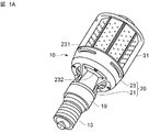
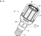
図1A及び図1Bを参照して本実施形態に係るLEDランプの例を説明する。LEDランプ10は、口金13と、口金13に接続された連結部材19と、連結部材19に装着された筐体20と、筐体20に取り付けられた円筒状の透光性のカバー31とを有する。筐体20は、接続部21とファン収納部23を含む。接続部21は、外径が比較的小さい連結部材19と外径が比較的大きいファン収納部23を接続する。ファン収納部23の円周状の縁にカバー31が接続されている。カバー31とファン収納部23によって、略円筒状の内部空間が形成される。本実施形態に係るLEDランプは所謂電球型である。LEDランプの内部構造は、図2を参照して説明する。
An example of the LED lamp according to the present embodiment will be described with reference to FIGS. 1A and 1B. The
図1Aに示すように、ファン収納部23に空気吸入孔231、232が形成されている。図1Bに示すように、カバー31のトップ側端部には空気排出孔32が形成されている。
As shown in FIG. 1A,
図2を参照して、本実施形態に係るLEDランプの内部構造を詳細に説明する。カバー31とファン収納部23によって形成された内部空間に、ヒートシンク11と冷却ファン15が配置されている。冷却ファン15は口金13とヒートシンク11の間に配置されている。ヒートシンク11と冷却ファン15の間に、リング状の断熱部材17が装着されている。断熱部材17によって、ヒートシンク11の熱が冷却ファンのモータ15に伝達されることが阻止される。
With reference to FIG. 2, the internal structure of the LED lamp which concerns on this embodiment is demonstrated in detail. The
ヒートシンク11は、カバー31の内部に配置されている。ヒートシンク11は筒状又は柱状であり、その中心軸線(対称軸)は、LEDランプの中心軸線に整合している。ヒートシンク11の各側面に基板30Bが装着されている。ヒートシンク11は基板を支持する支持体としても機能する。基板30Bは細長い矩形であってよい。本実施形態では、基板30Bは、LEDランプの中心軸線に平行に且つそれを囲むように配置されている。基板30B上には、複数のLED素子30Aが整列して装着されている。図示の例では、ヒートシンク11は8角柱状であるが、4角柱状等の多角柱状であってもよい。
The
ヒートシンク11は、熱伝導性が高い金属、例えば、銅、アルミニウム合金、等によって構成される。ヒートシンク11の内部には軸線方向に沿って貫通孔111が形成されている。この貫通孔の内面には、薄い板状の多数の放熱用のフィンが設けられている。フィンは、貫通孔の軸線方向に沿って全長に渡って延びている。フィンの形状は特に限定されない。
The
冷却ファン15は、略円筒形状のファン収納部23の内部に配置されている。冷却ファン15の中心軸線(回転軸線)は、LEDランプの中心軸線に整合している。冷却ファン15は、典型的にはケーシングとモータとファンを有する。モータは、直流ブラシレスモータであってよい。モータの周囲に環状の空気流路が形成される。この空気流路に回転羽根が配置されている。
The cooling
LEDランプの内部には、LED素子30A及び冷却ファン15に接続されたリード線が設けられているが、ここでは図示を省略している。
Inside the LED lamp, lead wires connected to the
図3を参照して、本実施形態に係るLEDランプの空冷システムを説明する。本実施形態によると、接続部21は、ファン収納部23に接続されたトップ側端部21aと連結部材19に接続された口金側端部21bとを有し、トップ側端部21aの外径は口金側端部21bの外径より小さい。即ち、接続部21の外形は、口金側からトップ側に向かって細くなっている。ファン収納部23は円筒部23Aと底面部23Bを有し、略円筒容器の形状を有する。ファン収納部23の底面部23Bの外径は、接続部21のトップ側端部21aより大きい。即ち、ファン収納部23の底面部23Bは、接続部21のトップ側端部21aを囲む環状に形成されている。
With reference to FIG. 3, the air cooling system of the LED lamp which concerns on this embodiment is demonstrated. According to this embodiment, the
ファン収納部23の円筒部23Aに第1の空気吸入孔231が形成され、ファン収納部23の底面部23Bに第2の空気吸入孔232が形成されている。カバー31のトップ側端部には空気排出孔32が形成されている。ファン収納部23とカバー31によって形成される内部空間は、空気吸入孔231、232と空気排出孔32によって外部空間に接続されている。
A first
上述のように、ヒートシンク11の内部には軸線方向に沿って貫通孔111が形成されている。貫通孔111の断面は、円形であってよいが、方形であってもよい。貫通孔111の中心軸線(回転軸線)は、LEDランプの中心軸線に整合している。貫通孔111は、冷却ファン15側の第1の開口とトップ側の第2の開口を有し、2つの開口の間は密閉空間を形成している。図示のように、貫通孔111のトップ側の第2の開口は、カバー31によって閉鎖されてよい。
As described above, the through
冷却ファン15は、円柱形状のモータ15Aとケーシング15Bを有し、モータ15Aの周囲に環状の空気流路151が形成される。この空気流路151に回転羽根が配置されている。ファン収納部23の円筒部23Aの内面とケーシング15Bの外面の間に部品用空間23Cが形成されている。部品用空間23Cに、ファン駆動用の回路部品、ケーブル類等が配置されている。
The cooling
ヒートシンク11の貫通孔111と冷却ファン15の環状の空気流路151は、整合して配置されている。更に、ファン収納部23の底面部23Bの第2の空気吸入孔232は、冷却ファン15の環状の空気流路151に接続されている。カバー31の空気排出孔32、ヒートシンク11の貫通孔111、冷却ファン15の環状の空気流路、及び、ファン収納部23の第2の空気吸入孔232は、LEDランプの中心軸線に沿って、且つそれを囲むように整合して配置されている。即ち、カバー31の空気排出孔32、ヒートシンク11の貫通孔111、冷却ファン15の環状の空気流路151、及び、ファン収納部23の第2の空気吸入孔232は、LEDランプの中心軸線に沿って一直線状に延びる空気流路を形成する。更に、ファン収納部23の円筒部23Aの第1の空気吸入孔231は、部品用空間23Cを介して冷却ファン15の環状の空気流路151に接続されている。
The through
冷却ファン15を回転させると、環状の空気流路151に軸線方向の冷却用空気流が形成される。矢印は、冷却用空気流の経路を示す。ファン収納部23の空気吸入孔231、232を経由して、外部空間から冷却ファン15の環状の空気流路151に比較的温度が低い空気が流れ込む。冷却用空気は、冷却ファン15を貫通し、ヒートシンク11の貫通孔111に導かれる。冷却用空気は、第1の開口から貫通孔111に入り、第2の開口から出る。本実施形態のLEDランプでは、冷却用空気は、LEDランプの中心軸線に沿って、冷却ファン15からトップ側に向けて流れる。冷却後の比較的温度が高い空気は、カバー31の空気排出孔32を経由してLEDランプ10の外部に排出される。
When the cooling
冷却用空気がヒートシンク11の貫通孔111に接触すると熱交換が行われ、冷却用空気はヒートシンク11より熱を奪う。本実施形態では、ヒートシンク11の貫通孔111は、両端の開口を除いて、密閉空間を有するから、冷却ファン15からの冷却用空気は全てヒートシンク11の貫通孔111内を通過し、ヒートシンク11の冷却に使用される。従って、ヒートシンク11を効率的に冷却することができる。こうして、LED30が高温となることはない。
When the cooling air contacts the through
本実施形態のLEDランプ10では、ファン収納部23の円筒部23A及び底面部23Bに設けられた空気吸入孔231、232から外部の空気が取り入れられて、ヒートシンク11の冷却用空気として用いられる。従って、ヒートシンク11及びそれに装着されたLED素子30Aを効果的に冷却することができる。
In the
本実施形態のLEDランプ10では、接続部21のトップ側端部21aの外径が比較的小さく形成されているため、ファン収納部23の第2の空気流入孔232の面積を大きくとれる。そのため、外部の空気を取り込み易くなる。また、接続部21の口金側端部21bの外径が比較的大きく形成されているため、接続部21と連結部19及び口金13の間の取り付け強度を大きくすることができる。そのため、ランプの取り付け取り外しにおける口金13の破損等を防止できる。
In the
更に、外部の空気は、先ず、ファン収納部23の内部に導かれる。従って、外部からの比較的低温の空気は、ファン収納部23に収納された冷却ファン15ばかりでなく、そこに配置された回路部品等に接触する。従って、冷却ファン15のモータ15Aばかりでなく、回路部品等の高温化を回避することができる。従って、冷却ファンのモータの潤滑油の劣化に起因する冷却ファンの性能低下を回避することができる。回路部品等の高温化に起因した劣化及び誤作動を防止することができる。
Further, the external air is first guided into the
以上、本実施形態に係るLEDランプについて説明したが、これらは例示であって、本発明の範囲を制限するものではない。当業者が、本実施形態に対して容易になしえる追加・削除・変更・改良等は、本発明の範囲内である。本発明の技術的範囲は、添付の特許請求の記載によって定められる。 As mentioned above, although the LED lamp which concerns on this embodiment was demonstrated, these are illustrations and do not restrict | limit the scope of the present invention. Additions, deletions, changes, improvements, and the like that can be easily made by those skilled in the art to the present embodiment are within the scope of the present invention. The technical scope of the present invention is defined by the appended claims.
10…LEDランプ、11…ヒートシンク、13…口金、15…冷却ファン、17…断熱部材、19…連結部材、20…筐体、21…接続部、21a…トップ側端部、21b…口金側端部、23…ファン収納部、23A…円筒部、23B…底面部、23C…部品用空間、30…LED、30A…LED素子、30B…基板、31…カバー、32…空気排出孔、111…貫通孔、151…空気流路、231、232…空気吸入孔
DESCRIPTION OF
Claims (5)
前記カバーは、前記ヒートシンクを覆うように形成され、前記口金と反対側の端部に空気排出孔を有し、
前記冷却ファンの空気流通路と前記ヒートシンクの貫通孔と前記カバーの空気排出孔はランプの中心軸線に平行な軸線に沿って一直線状に延びる空気流路を形成しており、
前記筐体は、前記冷却ファンを収納するファン収納部と該ファン収納部に接続された接続部とを有し、前記ファン収納部に空気吸入孔が形成されており、該空気吸入孔を経由して外部からの空気が前記冷却ファンに導かれ、
前記ファン収納部は円筒部と底面部とを有し、前記円筒部には第1の空気吸入孔が設けられ前記底面部には第2の空気吸入孔が設けられ、
前記ファン収納部に回路部品が配置され、該回路部品は前記第1の空気吸入孔を経由して外部から導かれた空気に接触するように構成されていることを特徴とするLEDランプ。 A base, a cylindrical heat sink having a through hole extending along the central axis, a substrate disposed on a side surface of the heat sink, an LED element mounted on the substrate, and the base and the heat sink are disposed between the base and the heat sink. A cooling fan, a casing that covers the cooling fan, and a light-transmitting cover that covers the substrate and the LED element, and the central axis of the cooling fan and the central axis of the heat sink are the central axes of the lamp Is consistent with
The cover is formed so as to cover the heat sink, and has an air discharge hole at an end opposite to the base.
The air flow passage of the cooling fan, the through hole of the heat sink, and the air discharge hole of the cover form an air flow path extending in a straight line along an axis parallel to the central axis of the lamp,
The housing includes a fan housing portion that houses the cooling fan and a connecting portion connected to the fan housing portion, and an air suction hole is formed in the fan housing portion, and the air suction hole passes through the air suction hole. Then, the air from the outside is led to the cooling fan,
The fan housing part has a cylindrical part and a bottom part, the cylindrical part is provided with a first air suction hole, and the bottom part is provided with a second air suction hole,
An LED lamp, wherein a circuit component is disposed in the fan housing portion, and the circuit component is configured to come into contact with air guided from the outside through the first air suction hole.
前記接続部は、前記ファン収納部に接続されたトップ側端部と該トップ側端部とは反対側の口金側端部とを有し、前記トップ側端部の外径は前記口金側端部の外径より小さいことを特徴とするLEDランプ。 The LED lamp according to claim 1, wherein
The connection part has a top side end connected to the fan housing part and a base side end opposite to the top side end, and the outer diameter of the top side end is the base side end. LED lamp characterized by being smaller than the outer diameter of the part.
前記回路部品はファン駆動用の回路を含むことを特徴とするLEDランプ。 The LED lamp according to claim 1 or 2,
The LED lamp according to claim 1, wherein the circuit component includes a circuit for driving a fan.
前記口金と前記筐体の間に絶縁性材料によって形成された連結部材が設けられていることを特徴とするLEDランプ。 In the LED lamp of any one of Claims 1-3,
An LED lamp, wherein a connecting member made of an insulating material is provided between the base and the casing.
前記冷却ファンと前記ヒートシンクの間に熱伝導性が低い材料によって形成された断熱部材が設けられていることを特徴とするLEDランプ。 In the LED lamp of any one of Claims 1-4,
An LED lamp, wherein a heat insulating member made of a material having low thermal conductivity is provided between the cooling fan and the heat sink.
Priority Applications (2)
| Application Number | Priority Date | Filing Date | Title |
|---|---|---|---|
| JP2014037948A JP6041158B2 (en) | 2014-02-28 | 2014-02-28 | LED lamp |
| PCT/JP2015/053127 WO2015129419A1 (en) | 2014-02-28 | 2015-02-04 | Led lamp |
Applications Claiming Priority (1)
| Application Number | Priority Date | Filing Date | Title |
|---|---|---|---|
| JP2014037948A JP6041158B2 (en) | 2014-02-28 | 2014-02-28 | LED lamp |
Publications (3)
| Publication Number | Publication Date |
|---|---|
| JP2015162414A JP2015162414A (en) | 2015-09-07 |
| JP2015162414A5 JP2015162414A5 (en) | 2016-04-07 |
| JP6041158B2 true JP6041158B2 (en) | 2016-12-07 |
Family
ID=54008745
Family Applications (1)
| Application Number | Title | Priority Date | Filing Date |
|---|---|---|---|
| JP2014037948A Active JP6041158B2 (en) | 2014-02-28 | 2014-02-28 | LED lamp |
Country Status (2)
| Country | Link |
|---|---|
| JP (1) | JP6041158B2 (en) |
| WO (1) | WO2015129419A1 (en) |
Cited By (1)
| Publication number | Priority date | Publication date | Assignee | Title |
|---|---|---|---|---|
| US11287103B2 (en) | 2019-04-22 | 2022-03-29 | Ism Lighting, Llc. | Low wattage balloon work light |
Families Citing this family (6)
| Publication number | Priority date | Publication date | Assignee | Title |
|---|---|---|---|---|
| CN105299509A (en) * | 2015-11-09 | 2016-02-03 | 繁昌县倍思生产力促进中心有限公司 | LED lamp |
| CN106195670A (en) * | 2016-08-31 | 2016-12-07 | 贵州明城科技有限公司 | A kind of radiator structure for LED |
| TWM575626U (en) | 2017-06-26 | 2019-03-11 | 美商米沃奇電子工具公司 | battery charger |
| JP7058095B2 (en) | 2017-09-22 | 2022-04-21 | 浜松ホトニクス株式会社 | Light source device |
| US11867363B2 (en) | 2020-02-11 | 2024-01-09 | Yuriy Borisovich Sokolov | LED lamp with molded housing/heatsink |
| CN113946083B (en) * | 2021-12-20 | 2022-05-20 | 深圳市爱图仕影像器材有限公司 | Lighting device |
Family Cites Families (11)
| Publication number | Priority date | Publication date | Assignee | Title |
|---|---|---|---|---|
| US7144140B2 (en) * | 2005-02-25 | 2006-12-05 | Tsung-Ting Sun | Heat dissipating apparatus for lighting utility |
| US20080055909A1 (en) * | 2006-09-01 | 2008-03-06 | Jia-Hao Li | Method for Combining LED Lamp and Heat Dissipator and Combination Structure thereof |
| CN101373064B (en) * | 2007-08-24 | 2011-05-11 | 富准精密工业(深圳)有限公司 | LED light fitting |
| DE102007040444B8 (en) * | 2007-08-28 | 2013-10-17 | Osram Gmbh | Led lamp |
| JP2010135181A (en) * | 2008-12-04 | 2010-06-17 | Sharp Corp | Illuminating device |
| KR101579220B1 (en) * | 2010-03-26 | 2015-12-23 | 주식회사 솔라코 컴퍼니 | Led lighting module and lighting lamp using the same |
| JP2012164512A (en) * | 2011-02-07 | 2012-08-30 | Jvc Kenwood Corp | Light source device |
| US10030863B2 (en) * | 2011-04-19 | 2018-07-24 | Cree, Inc. | Heat sink structures, lighting elements and lamps incorporating same, and methods of making same |
| JP2013065436A (en) * | 2011-09-16 | 2013-04-11 | Iris Ohyama Inc | Led lamp |
| US9188322B2 (en) * | 2012-03-26 | 2015-11-17 | Asia Vital Components Co., Ltd. | Heat dissipation structure for LED lighting |
| JP2014044935A (en) * | 2012-07-31 | 2014-03-13 | Mitsubishi Chemicals Corp | Lighting device |
-
2014
- 2014-02-28 JP JP2014037948A patent/JP6041158B2/en active Active
-
2015
- 2015-02-04 WO PCT/JP2015/053127 patent/WO2015129419A1/en active Application Filing
Cited By (1)
| Publication number | Priority date | Publication date | Assignee | Title |
|---|---|---|---|---|
| US11287103B2 (en) | 2019-04-22 | 2022-03-29 | Ism Lighting, Llc. | Low wattage balloon work light |
Also Published As
| Publication number | Publication date |
|---|---|
| JP2015162414A (en) | 2015-09-07 |
| WO2015129419A1 (en) | 2015-09-03 |
Similar Documents
| Publication | Publication Date | Title |
|---|---|---|
| JP6041158B2 (en) | LED lamp | |
| JP5975303B2 (en) | LED lamp and heat sink used therefor | |
| EP2397753B1 (en) | Led lamp and a heat sink thereof having a wound heat pipe | |
| US7637635B2 (en) | LED lamp with a heat sink | |
| EP2837882B1 (en) | Electric luminous body having heat dissipater with axial and radial air aperture | |
| US7810965B2 (en) | Heat removal system and method for light emitting diode lighting apparatus | |
| JP6325685B2 (en) | lighting equipment | |
| US8425086B2 (en) | Light emitting diode lamp structure | |
| JP6131891B2 (en) | Lighting fixtures and heat sinks | |
| JP2011187264A (en) | Lighting system | |
| JP5794440B2 (en) | Lighting fixture using LED lamp | |
| JP2015153706A (en) | Illuminating device | |
| WO2016103914A1 (en) | Led lamp | |
| WO2016098468A1 (en) | Led lamp | |
| JP2014135350A (en) | Heat sink | |
| JP2016115649A (en) | LED lamp | |
| WO2015122340A1 (en) | Led lamp and illumination apparatus using same | |
| WO2016098464A1 (en) | Led lamp | |
| JP5910893B2 (en) | LED lamp | |
| US20160201892A1 (en) | Lamp Base with Heat Dissipation Structure and Lamp Thereof, and Illumination Device | |
| JP2016122578A (en) | LED lamp | |
| JP5153551B2 (en) | Lighting device | |
| JP2016066694A (en) | Heat sink and illumination apparatus | |
| JP2012021698A (en) | Radiation fin and radiator | |
| JP6019497B2 (en) | LED lighting device |
Legal Events
| Date | Code | Title | Description |
|---|---|---|---|
| A521 | Request for written amendment filed |
Free format text: JAPANESE INTERMEDIATE CODE: A523 Effective date: 20160219 |
|
| A621 | Written request for application examination |
Free format text: JAPANESE INTERMEDIATE CODE: A621 Effective date: 20160219 |
|
| A871 | Explanation of circumstances concerning accelerated examination |
Free format text: JAPANESE INTERMEDIATE CODE: A871 Effective date: 20160219 |
|
| A975 | Report on accelerated examination |
Free format text: JAPANESE INTERMEDIATE CODE: A971005 Effective date: 20160510 |
|
| A131 | Notification of reasons for refusal |
Free format text: JAPANESE INTERMEDIATE CODE: A131 Effective date: 20160512 |
|
| A521 | Request for written amendment filed |
Free format text: JAPANESE INTERMEDIATE CODE: A523 Effective date: 20160707 |
|
| TRDD | Decision of grant or rejection written | ||
| A01 | Written decision to grant a patent or to grant a registration (utility model) |
Free format text: JAPANESE INTERMEDIATE CODE: A01 Effective date: 20161013 |
|
| A61 | First payment of annual fees (during grant procedure) |
Free format text: JAPANESE INTERMEDIATE CODE: A61 Effective date: 20161026 |
|
| R150 | Certificate of patent or registration of utility model |
Ref document number: 6041158 Country of ref document: JP Free format text: JAPANESE INTERMEDIATE CODE: R150 |
|
| S531 | Written request for registration of change of domicile |
Free format text: JAPANESE INTERMEDIATE CODE: R313531 |
|
| R350 | Written notification of registration of transfer |
Free format text: JAPANESE INTERMEDIATE CODE: R350 |
|
| S111 | Request for change of ownership or part of ownership |
Free format text: JAPANESE INTERMEDIATE CODE: R313111 |
|
| R350 | Written notification of registration of transfer |
Free format text: JAPANESE INTERMEDIATE CODE: R350 |