CN101588397B - Cradle device for portable terminal - Google Patents
Cradle device for portable terminal Download PDFInfo
- Publication number
- CN101588397B CN101588397B CN2009101462882A CN200910146288A CN101588397B CN 101588397 B CN101588397 B CN 101588397B CN 2009101462882 A CN2009101462882 A CN 2009101462882A CN 200910146288 A CN200910146288 A CN 200910146288A CN 101588397 B CN101588397 B CN 101588397B
- Authority
- CN
- China
- Prior art keywords
- portable terminal
- aforementioned
- terminal device
- place
- projections
- Prior art date
- Legal status (The legal status is an assumption and is not a legal conclusion. Google has not performed a legal analysis and makes no representation as to the accuracy of the status listed.)
- Expired - Fee Related
Links
Images


Classifications
-
- H—ELECTRICITY
- H04—ELECTRIC COMMUNICATION TECHNIQUE
- H04M—TELEPHONIC COMMUNICATION
- H04M1/00—Substation equipment, e.g. for use by subscribers
- H04M1/02—Constructional features of telephone sets
- H04M1/04—Supports for telephone transmitters or receivers
-
- B—PERFORMING OPERATIONS; TRANSPORTING
- B60—VEHICLES IN GENERAL
- B60R—VEHICLES, VEHICLE FITTINGS, OR VEHICLE PARTS, NOT OTHERWISE PROVIDED FOR
- B60R11/00—Arrangements for holding or mounting articles, not otherwise provided for
- B60R11/02—Arrangements for holding or mounting articles, not otherwise provided for for radio sets, television sets, telephones, or the like; Arrangement of controls thereof
- B60R11/0241—Arrangements for holding or mounting articles, not otherwise provided for for radio sets, television sets, telephones, or the like; Arrangement of controls thereof for telephones
-
- B—PERFORMING OPERATIONS; TRANSPORTING
- B60—VEHICLES IN GENERAL
- B60R—VEHICLES, VEHICLE FITTINGS, OR VEHICLE PARTS, NOT OTHERWISE PROVIDED FOR
- B60R11/00—Arrangements for holding or mounting articles, not otherwise provided for
- B60R11/02—Arrangements for holding or mounting articles, not otherwise provided for for radio sets, television sets, telephones, or the like; Arrangement of controls thereof
- B60R11/0252—Arrangements for holding or mounting articles, not otherwise provided for for radio sets, television sets, telephones, or the like; Arrangement of controls thereof for personal computers, e.g. laptops, notebooks
-
- G—PHYSICS
- G06—COMPUTING; CALCULATING OR COUNTING
- G06F—ELECTRIC DIGITAL DATA PROCESSING
- G06F1/00—Details not covered by groups G06F3/00 - G06F13/00 and G06F21/00
- G06F1/16—Constructional details or arrangements
- G06F1/1613—Constructional details or arrangements for portable computers
- G06F1/1632—External expansion units, e.g. docking stations
-
- H—ELECTRICITY
- H04—ELECTRIC COMMUNICATION TECHNIQUE
- H04B—TRANSMISSION
- H04B1/00—Details of transmission systems, not covered by a single one of groups H04B3/00 - H04B13/00; Details of transmission systems not characterised by the medium used for transmission
- H04B1/38—Transceivers, i.e. devices in which transmitter and receiver form a structural unit and in which at least one part is used for functions of transmitting and receiving
- H04B1/3827—Portable transceivers
- H04B1/3888—Arrangements for carrying or protecting transceivers
-
- G—PHYSICS
- G06—COMPUTING; CALCULATING OR COUNTING
- G06F—ELECTRIC DIGITAL DATA PROCESSING
- G06F1/00—Details not covered by groups G06F3/00 - G06F13/00 and G06F21/00
- G06F1/16—Constructional details or arrangements
- G06F1/1613—Constructional details or arrangements for portable computers
- G06F1/1626—Constructional details or arrangements for portable computers with a single-body enclosure integrating a flat display, e.g. Personal Digital Assistants [PDAs]
Landscapes
- Engineering & Computer Science (AREA)
- Theoretical Computer Science (AREA)
- Mechanical Engineering (AREA)
- Signal Processing (AREA)
- Computer Hardware Design (AREA)
- Human Computer Interaction (AREA)
- Physics & Mathematics (AREA)
- General Engineering & Computer Science (AREA)
- General Physics & Mathematics (AREA)
- Computer Networks & Wireless Communication (AREA)
- Telephone Set Structure (AREA)
Abstract
The present invention provides a cradle device for a portable terminal, which is provided with a plurality of projections (11, 18) engaged with the grooves (6, 7) that are provided on the upper end and the lower end of the portable terminal. The invention is characterized in that a rotary sliding cover (16) which is provided on the cradle device for the portable terminal to be used as a rotating part can be used as a loading table even at the state that the cradle device for the portable terminal is erected only through engaging two projections (4) of the cradle device for the portable terminal with two slots (6) on the upper part of the portable terminal without the engagement between the rest two projections (18) of the cradle device for the portable terminal and two slots (7) at the lower end of the portable terminal.
Description
The application is that denomination of invention is " cradle device for portable terminal ", to submit to day be that on September 5th, 2006 and application number are dividing an application of 200580007191.3 application for a patent for invention.
Technical field
The present invention relates to a kind of base device that portable terminal devices such as portable phone are installed, the outstanding base device of particularly a kind of portability.
Background technology
In recent years, along with the multifunction of portable terminal devices such as portable phone and portable information terminal develops rapidly, wish to realize requirement that these portable terminal devices are connected with other equipment and wish the increase of realization battery capacity in order to tackle the consumption electric power increase that brings because of the increase of service time etc.On the other hand, portable terminal device is from as its apparatus features, its portability of strong request still, i.e. lightweight and miniaturization.
In the past, as the technology that is used to satisfy these requirements of runing counter to, there was following example: make holder, be that the base device side has the incidental partial function of main functionality (for example, data communication use functions such as connector) to main body charging.
Along with the increase of base device side function, the necessity of carrying has also appearred in base device.For example, open 2001-101140 communique (document 1) and spy the spy and open in the 2003-110677 communique (document 2) and be characterised in that, base self is made the structure that can fold, make it have portability.In addition, in special permission No. 2711784 communique (document 3), mainly be conceived to improve the portability of the charger of battery pack.
But, in these base devices, exist several problems.
First problem is, in these examples, mainly is conceived to the portability of base as monomer, and do not consider the portability under portable terminal device and the state that base device is connected.When possessing the additional function that the portable terminal device main body do not have in the base device, also need to improve with the portability under base device and the state that portable terminal device is connected.
Second problem points is that the Mechanical Reliability of these base devices is low.Though considered the ease of connection with main body,, with state that base device is connected under, do not consider with the portable phone to be the terminal of the representative high degree of mechanical reliability when carrying.
Summary of the invention
The objective of the invention is to, it is that main body is carried equally easily, small-sized and cradle device for portable terminal that Mechanical Reliability is outstanding that a kind of and portable terminal device are provided.
The combination of cradle device for portable terminal of the present invention and portable terminal device of the present invention and cradle device for portable terminal is as described below.
1, a kind of cradle device for portable terminal is characterized in that, in the chimeric projection (11 and 18) of four jiaos of grooves that have and be arranged on four jiaos of portable terminal devices (6 and 7).
2, according to above-mentioned section 1 described cradle device for portable terminal, it is characterized in that, when the two place's projections (11) that make aforementioned cradle device for portable terminal are entrenched in two place's grooves (6) of aforementioned portable terminal device upper end, undertaken and being electrically connected of portable terminal device by the connector connecting portion (8) that is connected with the connector (3) of aforementioned portable terminal device, and, by the rotational slide mechanism (17) that has made up rotation and slided, carry out and keep two place's grooves (7) chimeric of the aforementioned relatively portable terminal device of residue two place's projections (18) bottom of aforementioned cradle device for portable terminal.
3, according to above-mentioned section 2 described cradle device for portable terminal, it is characterized in that, and then, mechanism as the aforementioned rotational slide of locking mechanism, has following mechanism: the L word sigmoid portion (17h) of clamping block (17e and 17f) on the sliding panel (17d) that is arranged at aforementioned rotational slide mechanism gone up slide, and fix, discharge the L word sigmoid portion (17j) that is arranged on the hinge (17a).
4, according to above-mentioned section 1 described cradle device for portable terminal, it is characterized in that, aforementioned cradle device for portable terminal is more outstanding to the front unlike the monitor (1) and the operating surface (2) of aforementioned portable terminal device, the processing ease of this portable terminal device under the state that is installed on the aforementioned portable terminal device, under the state that is installed on the aforementioned portable terminal device, utilization is arranged on the outstanding cord from neck on the aforementioned portable terminal device, can use under the state that hangs from neck.
5, according to above-mentioned section 2 described cradle device for portable terminal, it is characterized in that, only be fitted in two place's grooves (6) of aforementioned portable terminal device upper end by the two place's projections (11) that make aforementioned cradle device for portable terminal, and do not carry out two place's grooves (7) chimeric of the aforementioned relatively portable terminal device of residue two place's projections (18) bottom of aforementioned cradle device for portable terminal, under the state that does not lock aforementioned cradle device for portable terminal and had as the rotational slide lid (16) of rotating part part, utilize this rotational slide lid (16), even under the state that aforementioned cradle device for portable terminal is erected, also can use as mounting table.
6, the combination of a kind of portable terminal device and cradle device for portable terminal, it is characterized in that, be arranged on portable terminal device and cradle device for portable terminal four jiaos groove and projection separately is chimeric by making, aforementioned portable terminal device and aforementioned cradle device for portable terminal are installed.
Description of drawings
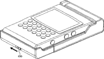
Fig. 1 is the stereogram of the base device of one embodiment of the present invention.
Fig. 2 is the stereogram of observing from the opposing face of the base device of Fig. 1.
Fig. 3 is the exploded view of the base device of Fig. 1.
Fig. 4 is the stereogram of portable terminal device of the base device of installation diagram 1.
Fig. 5 is the stereogram of observing from the back side of aforementioned portable terminal device.
Fig. 6 is the figure that the base device of Fig. 1 is installed to aforementioned portable terminal device.
Fig. 7 is the rearview of Fig. 6.
Fig. 8 is the figure of the action of the above-mentioned execution mode of expression.
Fig. 9 is the figure of the action of the above-mentioned execution mode of expression.
Figure 10 is the figure of the action of the above-mentioned execution mode of expression.
Figure 11 is the figure of the action of the above-mentioned execution mode of expression.
Figure 12 is the figure of the action of the above-mentioned execution mode of expression.
Figure 13 is the figure of the action of the above-mentioned execution mode of expression.
Figure 14 is the figure of the action of the above-mentioned execution mode of expression.
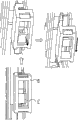
Figure 15 A, Figure 15 B and Figure 15 C are the figure of action of the rotational slide mechanism of the above-mentioned execution mode of expression.
Figure 16 is the figure of action of the rotational slide mechanism of the above-mentioned execution mode of expression.
Figure 17 is that another of base device of the above-mentioned execution mode of expression makes the figure of use-case.
Description of reference numerals
1 monitor, 2 front-operated portions, 3 multifrnction connectors, 4 cameras, 5 side operating portions, 6 upper slots, 7 lower channel, 8 connector connecting portions, 9 slip bands, 10 outside multifrnction connector, 11 projections, 12 circuit substrates of connecting, 13 internal batteries, 14 loam cakes, 15 bottoms, 16 rotational slides lid, 17 rotational slide mechanisms.
Embodiment
Below, with reference to accompanying drawing, embodiments of the present invention are elaborated.
Base of the present invention (cradle) device is a kind of base device that is connected with portable terminal device, described portable terminal device disposes on top and is used for the connector that is connected with external electric, and make in profile four jiaos and be provided with groove and can make base device remain in structure in this groove, described base device is characterised in that to have by making portable terminal device slide, make reliably base device and the chimeric structure of groove that is provided with on connector portion and main body; And have following structure, that is, and have with opposed of connector on make the mechanism of base device rotational slide so that base device is chimeric reliably with the groove that is arranged on the main body.
In the present invention, if along the chimeric portable terminal device of the projection of base device, then when carrying out the controlling of portable terminal device top, finish the connection between the connector.And, by making the slip rotating part rotate about 80 °, and then make its slip, make the groove that is arranged on the portable terminal device and be arranged on rotational slide projection partly chimeric, carry out controlling of portable terminal device bottom, and, accidentally base is separated with portable terminal device when preventing to use usually by locking switch.
Fig. 1 is the stereogram of the base device of one embodiment of the present invention.Fig. 2 is the stereogram of observing from the opposing face of the base device of Fig. 1.Fig. 3 is the exploded view of the base device of Fig. 1.Fig. 4 is the portable terminal device of the base device of installation diagram 1.Fig. 5 is the stereogram of observing from the back side of this portable terminal device.Fig. 6 is the figure that the base device of Fig. 1 is installed to this portable terminal device.Fig. 7 is the rearview of Fig. 6.
Portable terminal device comprises monitor 1, front-operated portion 2, the multifrnction connector 3 among Fig. 4, the camera among Fig. 5 (camera) 4, side operating portion 5.And among Fig. 4, be provided with upper slot 6 in the both sides, top, be provided with lower channel 7 in the both sides, bottom.The multifrnction connector 3 of Fig. 4 is to have the connector of charging with various functions such as cable connection, earphone Mike connection, the connections of data communication cable.
Base device comprises connector connecting portion 8, the slip band 9 among Fig. 1, among Fig. 2 two are locational outsidely to connect multifrnction connectors 10, be used for the projection 11 (Fig. 1) chimeric with the upper slot 6 of portable terminal device, the circuit substrate 12 among Fig. 3, internal battery 13, loam cake 4, bottom 15, rotational slide lid 16 and rotational slide mechanism 17.Among Fig. 2, rotational slide lid 16 is provided with the projection 18 chimeric with the lower channel 7 of portable terminal device.The outside multifrnction connector 10 that connects in two places is set as shown in Figure 2 can plays following effects: only use portable terminal device, can only use a kind of function in the multiple function all the time, still,, can use two kinds of functions simultaneously by this base device is installed.
Below, rotational slide mechanism 17 shown in Figure 8 is described.Rotational slide mechanism 17 comprises: the hinge 17a that is rotated action; Become the axle 17b of rotating shaft; The hinge retainer 17c of supporting hinges 17a; Together support the sliding panel 17d of the motion of rectilinear direction with respect to hinge 17a and rotational slide lid 16; Clamping block 17e moves on the direction with respect to sliding panel 17d quadrature, according to the difference of its position, perhaps makes hinge 17a and sliding panel 17d can carry out the sliding action of rectilinear direction or carries out fixing on the off-position; Clamping block 17f with operational lock piece 17e.
Then, with reference to Fig. 9~Figure 16, the action of first execution mode is described.
As shown in Figure 9,, cover under 16 states that open wide, as shown in figure 10, insert portable terminal device along the direction of arrow with monitor 1 and front-operated portion 2 state up in the rotational slide of base device as initial condition.At first, the upper slot 6 of portable terminal device is chimeric with projection 11, and then, the connector of connector connecting portion 8 is inserted in the multifrnction connector 3 (Fig. 4).Connector connecting portion 8 is provided with the small degree of freedom for the dimensional tolerance that absorbs both.
As shown in figure 11, after inserting portable terminal device, make 16 rotations of rotational slide lid, under the parallel state (Figure 12) of the lower channel 7 of the projection 18 of rotational slide lid 16 and main body, further make 16 slips of rotational slide lid, make lower channel 7 and projection 18 chimeric.At this moment, because it is chimeric to be arranged on the fixed projection 16a of holddown groove 14a and the rotational slide lid 16 on the loam cake 14, so, even portable terminal device is not installed, also rotational slide can be covered 16 by slip and be fixed on the loam cake 14.As a result, the projection of four positions by making the groove that is arranged on four jiaos of portable terminal devices and this base device is chimeric, and portable terminal device and this base device link together very securely.And then, as Figure 13 and shown in Figure 14,, make it be not easy to open by locking with locking switch 100.
Then, the action to rotational slide mechanism 17 describes in Fig. 8.Hinge 17a as rotating shaft, can rotate freely axle 17b.Doing on hinge 17a has leaf spring 17g, is embedded into by the projection that makes leaf spring 17g in the hole of sliding panel 17d, and slip is stopped two positions.In this mechanism, shown in Figure 15 A, further crooked this sliding panel 17d, with the part that vertically the erects track 17h as convex, (having the clamping block 17e of Fig. 8 and 17f) sliding shoe (locking switch) 100 is by the groove 17i move left and right that is arranged on the sliding shoe.The track centre part of sliding panel 17d is cut, and shown in Figure 15 B and Figure 15 C, the lock pawl 17j of hinge 17a moves forward and backward in this part.That is, when hinge 17a with respect to the state of sliding panel 17d elongation, sliding panel 17d and hinge 17a away from direction on position when stopping, as shown in figure 16, can't make the locking switch move left and right.On the other hand, when hinge 17a is stopped with the state that shrinking with respect to sliding panel 17d, position on the close direction of sliding panel 17d and hinge 17a, locking switch can move, if locking switch is moved, then the groove of the lock pawl of hinge 17a in the locking switch is embedded in the groove of locking switch.
And cradle device for portable terminal of the present invention also can be as shown in figure 17, only makes upper slot chimeric and not fixedly under the state of rotational slide portion, use as mounting table.
In addition, in the above-described embodiment, can not fix yet, and on these both sides of projection of the groove of portable terminal device and base device, ladder is set, carry out simple and easy locking thus by locking switch.
The invention effect
First effect of the present invention is the portable outstanding base device in the time of accessing the connection of portable terminal device main body.
Second effect of the present invention is by operating four jiaos that keep portable terminal device reliably with simple mechanism with easy, can protect main body reliably when descending drop impact.
The 3rd effect of the present invention is, owing to make on four jiaos the projection of that be provided with, portable terminal device respectively groove and base device chimeric, so, do not need to make the framework of base device around front face side to portable terminal device, thus, when using portable terminal device under the state that has connected base device, base device can not become obstruction.
Quadruple effect of the present invention really is, not fixedly under the state of rotating part, also can be used as holder.
Claims (1)
1. a cradle device for portable terminal has and the chimeric a plurality of projections (11 and 18) of groove (6 and 7) that are arranged on the upper end and the bottom of portable terminal device, it is characterized in that,
On the rotational slide lid (16) that aforementioned cradle device for portable terminal had as the rotating part part, be provided with the two place projections (18) chimeric with two place's grooves (7) of aforementioned portable terminal device bottom,
Aforementioned portable terminal device is with in the device, make two place's projections of aforementioned cradle device for portable terminal, (11) be fitted to two place's grooves of aforementioned portable terminal device upper end, (6) in, and, by rotational slide mechanism, (17), carry out and keep residue two place's projections of aforementioned cradle device for portable terminal, (18) two place's grooves of aforementioned relatively portable terminal device bottom, (7) chimeric, described rotational slide mechanism, (17) be to make aforementioned rotational slide lid, (16) two place's projections, (18) rotate laggard line slip, make the groove of aforementioned portable terminal device, (7) and projection, (18) chimeric mechanism
Only be fitted in two place's grooves (6) of aforementioned portable terminal device upper end by the two place's projections (11) that make aforementioned cradle device for portable terminal, and do not carry out making its slip after two place's grooves (7) rotation of the aforementioned relatively portable terminal device of two place's projections (18) bottom of aforementioned rotational slide lid (16) and carry out chimeric, utilize aforementioned rotational slide lid (16), even under the state that aforementioned cradle device for portable terminal is erected, also can use as mounting table.
Applications Claiming Priority (3)
| Application Number | Priority Date | Filing Date | Title |
|---|---|---|---|
| JP2004062158 | 2004-03-05 | ||
| JP2004-062158 | 2004-03-05 | ||
| JP2004062158 | 2004-03-05 |
Related Parent Applications (1)
| Application Number | Title | Priority Date | Filing Date |
|---|---|---|---|
| CN200580007191A Division CN100586131C (en) | 2004-03-05 | 2005-03-04 | Cradle device for portable terminal |
Publications (2)
| Publication Number | Publication Date |
|---|---|
| CN101588397A CN101588397A (en) | 2009-11-25 |
| CN101588397B true CN101588397B (en) | 2011-11-16 |
Family
ID=34918107
Family Applications (2)
| Application Number | Title | Priority Date | Filing Date |
|---|---|---|---|
| CN200580007191A Expired - Fee Related CN100586131C (en) | 2004-03-05 | 2005-03-04 | Cradle device for portable terminal |
| CN2009101462882A Expired - Fee Related CN101588397B (en) | 2004-03-05 | 2005-03-04 | Cradle device for portable terminal |
Family Applications Before (1)
| Application Number | Title | Priority Date | Filing Date |
|---|---|---|---|
| CN200580007191A Expired - Fee Related CN100586131C (en) | 2004-03-05 | 2005-03-04 | Cradle device for portable terminal |
Country Status (5)
| Country | Link |
|---|---|
| US (1) | US7669829B2 (en) |
| EP (1) | EP1732291A4 (en) |
| JP (1) | JP4269185B2 (en) |
| CN (2) | CN100586131C (en) |
| WO (1) | WO2005086466A1 (en) |
Families Citing this family (59)
| Publication number | Priority date | Publication date | Assignee | Title |
|---|---|---|---|---|
| US9003426B2 (en) | 2011-12-09 | 2015-04-07 | Z124 | Physical key secure peripheral interconnection |
| US9507930B2 (en) | 2003-04-25 | 2016-11-29 | Z124 | Physical key secure peripheral interconnection |
| US20130198867A1 (en) | 2011-12-09 | 2013-08-01 | Z124 | A Docking Station for Portable Devices Providing Authorized Power Transfer and Facility Access |
| KR100678199B1 (en) * | 2005-06-14 | 2007-02-02 | 삼성전자주식회사 | Portable terminal with sliding module |
| JP5027421B2 (en) * | 2006-02-08 | 2012-09-19 | シャープ株式会社 | Charger for portable electronic devices |
| JP5057120B2 (en) * | 2007-12-14 | 2012-10-24 | 富士通株式会社 | Holding stand and information processing system |
| US8367235B2 (en) | 2008-01-18 | 2013-02-05 | Mophie, Inc. | Battery pack, holster, and extendible processing and interface platform for mobile devices |
| JP5405070B2 (en) | 2008-09-03 | 2014-02-05 | 株式会社東芝 | Ultrasound diagnostic system and installation base for ultrasonic diagnostic equipment |
| GB2464352A (en) * | 2008-10-17 | 2010-04-21 | Native Design Ltd | Media player support |
| US7782610B2 (en) * | 2008-11-17 | 2010-08-24 | Incase Designs Corp. | Portable electronic device case with battery |
| IT1392095B1 (en) * | 2008-12-04 | 2012-02-09 | Evotek Engineering S R L | SUPPORT EQUIPMENT FOR PORTABLE DEVICES. |
| DE102009009447B3 (en) * | 2009-02-13 | 2010-09-16 | Funkwerk Dabendorf Gmbh | Holder for a mobile electronic device for temporarily fixing the device to the holder |
| JP2013530628A (en) | 2010-05-19 | 2013-07-25 | モフィー・インコーポレーテッド | Modular mobile accessories for mobile devices |
| US8930605B2 (en) * | 2010-10-01 | 2015-01-06 | Z124 | Systems and methods for docking portable electronic devices |
| FR2968491B1 (en) * | 2010-12-07 | 2013-09-06 | Ingenico Sa | MODULAR INTERFACE INCLUDING AN ELECTRONIC PAYMENT TERMINAL WITH ARTICULATION OF A COVER BY TRANSLATION AND ROTATION. |
| AU2011340661B2 (en) * | 2010-12-07 | 2016-02-25 | Compagnie Industrielle Et Financiere D'ingenierie "Ingenico" | Payment terminal comprising a payment device and a modular interface forming a shroud or hood for pairing a communication terminal |
| FR2968419B1 (en) * | 2010-12-07 | 2013-02-15 | Ingenico Sa | POWER SUPPLY BASE FOR ELECTRONIC PAYMENT TERMINAL AND ELECTRONIC PAYMENT TERMINAL. |
| FR2968492B1 (en) * | 2010-12-07 | 2013-09-06 | Ingenico Sa | PAYMENT TERMINAL COMPRISING A PAYMENT DEVICE AND A MODULAR INTERFACE FORMING A HOOD OR CASE FOR APPAIRING A COMMUNICATION TERMINAL. |
| BR112013013805B1 (en) * | 2010-12-07 | 2022-03-29 | Compagnie Industrielle Et Financiere D'ingenierie - Ingenico | Modular interface included in an electronic terminal, with the hinge of a cover by means of translation and rotation and terminal |
| WO2012076569A2 (en) | 2010-12-07 | 2012-06-14 | Compagnie Industrielle Et Financiere D'ingenierie "Ingenico" | Power supply base for electronic payment terminal and electronic payment terminal |
| KR101760747B1 (en) | 2010-12-20 | 2017-07-24 | 엘지전자 주식회사 | Mobile terminal |
| CN102537621B (en) * | 2010-12-30 | 2016-05-18 | 富泰华工业(深圳)有限公司 | Electronic installation support and with the electronic equipment of electronic installation support |
| US9095323B2 (en) | 2011-04-01 | 2015-08-04 | JusJas LLC | Holder removably mountable on associated device |
| WO2012170964A2 (en) | 2011-06-10 | 2012-12-13 | Mophie, Inc. | Wireless communication accessory for a mobile device |
| US9244491B2 (en) | 2011-08-31 | 2016-01-26 | Z124 | Smart dock for auxiliary devices |
| US9383770B2 (en) | 2011-08-31 | 2016-07-05 | Z124 | Mobile device that docks with multiple types of docks |
| US9246353B2 (en) | 2011-08-31 | 2016-01-26 | Z124 | Smart dock charging |
| US9351237B2 (en) | 2011-09-27 | 2016-05-24 | Z124 | Displaying of charging status on dual screen device |
| JP2012016277A (en) * | 2011-10-03 | 2012-01-19 | Sharp Corp | Charger of portable electronic apparatus |
| US9086840B2 (en) | 2011-12-09 | 2015-07-21 | Z124 | RSID proximity peripheral interconnection |
| US8631934B2 (en) * | 2012-02-14 | 2014-01-21 | James K Chun | Multi-functional video device support accessory |
| SG195411A1 (en) | 2012-05-24 | 2013-12-30 | Sony Corp | Connecting multiple electronic devices |
| TWI498709B (en) * | 2012-06-18 | 2015-09-01 | Wistron Corp | Electronic device and supporting mechanism thereof |
| CN103511800A (en) * | 2012-06-28 | 2014-01-15 | 鸿富锦精密工业(深圳)有限公司 | Electronic device support with protection function |
| USD723532S1 (en) | 2013-02-11 | 2015-03-03 | Dean Stevinson | Combo earphone case |
| USD726701S1 (en) | 2013-02-11 | 2015-04-14 | Dean Stevinson | Exoskeleton combo case |
| USD735706S1 (en) | 2013-02-11 | 2015-08-04 | Dean Stevinson | Separable exoskeleton earphone case |
| USD730315S1 (en) | 2013-02-11 | 2015-05-26 | Dean Stevinson | Earphone caddy |
| US9755444B2 (en) | 2013-02-25 | 2017-09-05 | Mophie, Inc. | Protective case with switch cover |
| EP2974044A4 (en) | 2013-03-15 | 2016-11-09 | Mophie Inc | Protective case for mobile device |
| USD744470S1 (en) | 2013-04-26 | 2015-12-01 | Dean Stevinson | Combo case having domed portion |
| US9495375B2 (en) | 2013-11-27 | 2016-11-15 | Mophie, Inc. | Battery pack with supplemental memory |
| US10079496B2 (en) | 2014-09-03 | 2018-09-18 | Mophie Inc. | Systems for managing charging devices based on battery health information |
| USD776080S1 (en) * | 2014-10-02 | 2017-01-10 | Zound Industries International Ab | Headphone hinge |
| USD797092S1 (en) | 2014-11-25 | 2017-09-12 | Mophie, Inc. | Case for a mobile electronic device |
| USD797091S1 (en) | 2014-11-25 | 2017-09-12 | Mophie, Inc. | Case for a mobile electronic device |
| FR3029335B1 (en) * | 2014-12-01 | 2020-09-18 | Compagnie Ind Et Financiere Dingenierie Ingenico | HATCH FOR PAYMENT DEVICE INCLUDING A PAYMENT TERMINAL AND A MAINTAINING HOUSING OF A COMMUNICATION TERMINAL. |
| USD797093S1 (en) | 2014-12-03 | 2017-09-12 | Mophie, Inc. | Case for a mobile electronic device |
| US9356267B1 (en) | 2014-12-17 | 2016-05-31 | Mophie, Inc. | Protective battery case to partially enclose a mobile electronic device |
| USD766819S1 (en) | 2015-04-06 | 2016-09-20 | Mophie, Inc. | Protective battery case |
| USD767485S1 (en) | 2015-04-07 | 2016-09-27 | Mophie, Inc. | Battery case |
| USD861653S1 (en) | 2015-05-27 | 2019-10-01 | Mophie Inc. | Protective battery case for mobile communications device |
| JP6009704B1 (en) * | 2016-01-19 | 2016-10-19 | 株式会社Pga | Sliding notebook type carrying case |
| USD950538S1 (en) * | 2016-03-03 | 2022-05-03 | Mophie Inc. | Case for a mobile electronic device |
| KR101891660B1 (en) * | 2016-05-20 | 2018-08-24 | 두산중공업 주식회사 | Data acquisition apparatus |
| ITUA20164163A1 (en) * | 2016-06-07 | 2017-12-07 | Mauro Lini | MOBILE PHONE |
| CN107592390B (en) * | 2017-10-19 | 2020-01-14 | Oppo广东移动通信有限公司 | From rapping bar |
| US10516431B2 (en) | 2017-11-21 | 2019-12-24 | Mophie Inc. | Mobile device case for receiving wireless signals |
| USD931859S1 (en) * | 2019-07-15 | 2021-09-28 | Yinjia FANG | Computer hub case |
Family Cites Families (16)
| Publication number | Priority date | Publication date | Assignee | Title |
|---|---|---|---|---|
| US5100098A (en) * | 1989-06-12 | 1992-03-31 | Grid Systems Corporation | Stand and handle for hand held computer |
| US4969830A (en) * | 1989-06-12 | 1990-11-13 | Grid Systems Corporation | Connection between portable computer components |
| EP0530829A2 (en) * | 1991-09-06 | 1993-03-10 | Kabushiki Kaisha Toshiba | Electronic apparatus system having an electronic apparatus unit and an expansion unit for expanding the function of the electronic apparatus unit |
| JP2711784B2 (en) | 1992-11-16 | 1998-02-10 | ユピテル工業株式会社 | Battery pack charger |
| US5548824A (en) * | 1993-08-25 | 1996-08-20 | Mitsubishi Denki Kabushiki Kaisha | Portable radio communication device housing having a battery storage unit |
| US5478037A (en) * | 1994-06-20 | 1995-12-26 | Haltof; Garry P. | Pull release bracket |
| JP3196098B2 (en) * | 1994-07-04 | 2001-08-06 | 京セラ株式会社 | Mobile phone charger lock mechanism |
| JP2658909B2 (en) * | 1994-09-30 | 1997-09-30 | 日本電気株式会社 | Mobile phone holder |
| JP2000504543A (en) * | 1996-12-06 | 2000-04-11 | コーニンクレッカ フィリップス エレクトロニクス エヌ ヴィ | Telephone |
| CN1212099A (en) * | 1996-12-24 | 1999-03-24 | 皇家菲利浦电子有限公司 | Holder for telephone handset and assembly of holder and telephone handset |
| US5996956A (en) * | 1997-06-17 | 1999-12-07 | Shawver; Michael | Mounting platform for an electronic device |
| JP2001101140A (en) | 1999-09-30 | 2001-04-13 | Pfu Ltd | Cradle for personal digital assistants |
| JP4183158B2 (en) * | 2000-08-28 | 2008-11-19 | 京セラ株式会社 | Charger |
| JP2002117817A (en) * | 2000-10-04 | 2002-04-19 | Matsushita Electric Ind Co Ltd | Locking device of charger |
| JP3699027B2 (en) | 2001-09-28 | 2005-09-28 | Necパーソナルプロダクツ株式会社 | Place for portable information terminal |
| JP3884320B2 (en) | 2002-04-23 | 2007-02-21 | 株式会社東芝 | Charger for portable electronic devices |
-
2005
- 2005-03-04 JP JP2006510818A patent/JP4269185B2/en not_active Expired - Fee Related
- 2005-03-04 WO PCT/JP2005/004267 patent/WO2005086466A1/en active Application Filing
- 2005-03-04 EP EP05720538A patent/EP1732291A4/en not_active Withdrawn
- 2005-03-04 CN CN200580007191A patent/CN100586131C/en not_active Expired - Fee Related
- 2005-03-04 CN CN2009101462882A patent/CN101588397B/en not_active Expired - Fee Related
- 2005-03-04 US US10/591,755 patent/US7669829B2/en not_active Expired - Fee Related
Also Published As
| Publication number | Publication date |
|---|---|
| US7669829B2 (en) | 2010-03-02 |
| JP4269185B2 (en) | 2009-05-27 |
| CN1930856A (en) | 2007-03-14 |
| CN101588397A (en) | 2009-11-25 |
| WO2005086466A1 (en) | 2005-09-15 |
| EP1732291A1 (en) | 2006-12-13 |
| CN100586131C (en) | 2010-01-27 |
| JPWO2005086466A1 (en) | 2008-01-24 |
| EP1732291A4 (en) | 2008-12-31 |
| US20070187563A1 (en) | 2007-08-16 |
Similar Documents
| Publication | Publication Date | Title |
|---|---|---|
| CN101588397B (en) | Cradle device for portable terminal | |
| KR100630069B1 (en) | Swing hinge device for mobile phone | |
| EP1805903B1 (en) | Camera rotating apparatus of portable terminal | |
| US7988468B2 (en) | Protective cover mechanism and portable electronic device using same | |
| US20060083158A1 (en) | Portable storage device with multiple data interfaces | |
| US6561824B1 (en) | Media connector interface for electrical apparatus | |
| CA2723140A1 (en) | Docking station | |
| KR20050077513A (en) | Rotary type hinge apparatus for portable terminal | |
| KR20160142186A (en) | Electronic device | |
| EP1569421A1 (en) | Portable communication apparatus having triple-axis hinge folder and rotation locking device thereof | |
| CN100508705C (en) | Slide module for portable terminal and cover device of external card mounted on it | |
| US8244322B2 (en) | Protective cover mechanism | |
| WO2007013672A1 (en) | Electronic device and casing used therefor | |
| EP1439685A1 (en) | Flip-phone cover | |
| US20190363555A1 (en) | Portable wireless charging apparatus | |
| CN210007730U (en) | Mobile terminal | |
| JP4566181B2 (en) | Folding hinge device and personal portable terminal using the folding hinge device | |
| CN113314864B (en) | Electronic device | |
| CN210041886U (en) | Electronic device | |
| US6619982B2 (en) | Charge adapter for charging and performing data communications | |
| CN210120640U (en) | Storage box | |
| JP4145182B2 (en) | Charger for mobile phone | |
| JP4165006B2 (en) | Charger | |
| JP2011244156A (en) | Portable terminal | |
| KR100640370B1 (en) | Hinge apparatus for portable terminal |
Legal Events
| Date | Code | Title | Description |
|---|---|---|---|
| C06 | Publication | ||
| PB01 | Publication | ||
| C10 | Entry into substantive examination | ||
| SE01 | Entry into force of request for substantive examination | ||
| C14 | Grant of patent or utility model | ||
| GR01 | Patent grant | ||
| CF01 | Termination of patent right due to non-payment of annual fee |
Granted publication date: 20111116 Termination date: 20150304 |
|
| EXPY | Termination of patent right or utility model |