EP1805903B1 - Camera rotating apparatus of portable terminal - Google Patents
Camera rotating apparatus of portable terminal Download PDFInfo
- Publication number
- EP1805903B1 EP1805903B1 EP05817634A EP05817634A EP1805903B1 EP 1805903 B1 EP1805903 B1 EP 1805903B1 EP 05817634 A EP05817634 A EP 05817634A EP 05817634 A EP05817634 A EP 05817634A EP 1805903 B1 EP1805903 B1 EP 1805903B1
- Authority
- EP
- European Patent Office
- Prior art keywords
- hinge
- main body
- portable terminal
- head portion
- case
- Prior art date
- Legal status (The legal status is an assumption and is not a legal conclusion. Google has not performed a legal analysis and makes no representation as to the accuracy of the status listed.)
- Not-in-force
Links
Images


Classifications
-
- H—ELECTRICITY
- H04—ELECTRIC COMMUNICATION TECHNIQUE
- H04B—TRANSMISSION
- H04B1/00—Details of transmission systems, not covered by a single one of groups H04B3/00 - H04B13/00; Details of transmission systems not characterised by the medium used for transmission
- H04B1/38—Transceivers, i.e. devices in which transmitter and receiver form a structural unit and in which at least one part is used for functions of transmitting and receiving
- H04B1/40—Circuits
-
- H—ELECTRICITY
- H04—ELECTRIC COMMUNICATION TECHNIQUE
- H04M—TELEPHONIC COMMUNICATION
- H04M1/00—Substation equipment, e.g. for use by subscribers
- H04M1/02—Constructional features of telephone sets
- H04M1/0202—Portable telephone sets, e.g. cordless phones, mobile phones or bar type handsets
- H04M1/026—Details of the structure or mounting of specific components
- H04M1/0264—Details of the structure or mounting of specific components for a camera module assembly
-
- G—PHYSICS
- G03—PHOTOGRAPHY; CINEMATOGRAPHY; ANALOGOUS TECHNIQUES USING WAVES OTHER THAN OPTICAL WAVES; ELECTROGRAPHY; HOLOGRAPHY
- G03B—APPARATUS OR ARRANGEMENTS FOR TAKING PHOTOGRAPHS OR FOR PROJECTING OR VIEWING THEM; APPARATUS OR ARRANGEMENTS EMPLOYING ANALOGOUS TECHNIQUES USING WAVES OTHER THAN OPTICAL WAVES; ACCESSORIES THEREFOR
- G03B17/00—Details of cameras or camera bodies; Accessories therefor
- G03B17/02—Bodies
- G03B17/04—Bodies collapsible, foldable or extensible, e.g. book type
-
- H—ELECTRICITY
- H04—ELECTRIC COMMUNICATION TECHNIQUE
- H04M—TELEPHONIC COMMUNICATION
- H04M1/00—Substation equipment, e.g. for use by subscribers
- H04M1/02—Constructional features of telephone sets
- H04M1/0202—Portable telephone sets, e.g. cordless phones, mobile phones or bar type handsets
- H04M1/0206—Portable telephones comprising a plurality of mechanically joined movable body parts, e.g. hinged housings
- H04M1/0247—Portable telephones comprising a plurality of mechanically joined movable body parts, e.g. hinged housings comprising more than two body parts
-
- H—ELECTRICITY
- H04—ELECTRIC COMMUNICATION TECHNIQUE
- H04M—TELEPHONIC COMMUNICATION
- H04M1/00—Substation equipment, e.g. for use by subscribers
- H04M1/02—Constructional features of telephone sets
- H04M1/0202—Portable telephone sets, e.g. cordless phones, mobile phones or bar type handsets
- H04M1/0206—Portable telephones comprising a plurality of mechanically joined movable body parts, e.g. hinged housings
- H04M1/0208—Portable telephones comprising a plurality of mechanically joined movable body parts, e.g. hinged housings characterized by the relative motions of the body parts
- H04M1/021—Portable telephones comprising a plurality of mechanically joined movable body parts, e.g. hinged housings characterized by the relative motions of the body parts using combined folding and rotation motions
- H04M1/0212—Portable telephones comprising a plurality of mechanically joined movable body parts, e.g. hinged housings characterized by the relative motions of the body parts using combined folding and rotation motions with a two degrees of freedom mechanism, i.e. folding around a first axis and rotating around a second axis perpendicular to the first
-
- H—ELECTRICITY
- H04—ELECTRIC COMMUNICATION TECHNIQUE
- H04M—TELEPHONIC COMMUNICATION
- H04M1/00—Substation equipment, e.g. for use by subscribers
- H04M1/02—Constructional features of telephone sets
- H04M1/0202—Portable telephone sets, e.g. cordless phones, mobile phones or bar type handsets
- H04M1/0206—Portable telephones comprising a plurality of mechanically joined movable body parts, e.g. hinged housings
- H04M1/0208—Portable telephones comprising a plurality of mechanically joined movable body parts, e.g. hinged housings characterized by the relative motions of the body parts
- H04M1/0235—Slidable or telescopic telephones, i.e. with a relative translation movement of the body parts; Telephones using a combination of translation and other relative motions of the body parts
- H04M1/0237—Sliding mechanism with one degree of freedom
Definitions
- the present invention relates to a camera rotating apparatus of a portable terminal.
- a camera has been provided on a portable terminal such as a mobile phone.
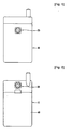
- FIG. 1 shows a conventional folder type mobile phone where a camera 20 is fixedly mounted on a main body case 10.
- FIG. 2 shows another conventional folder type mobile phone where a battery 40 is coupled to a rear portion of a main body case 10 and a camera 20 is fixedly mounted above the battery 40 on the rear portion of the main body case 10.
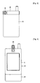
- FIG. 3 shows still another conventional mobile phone where a camera 20 is rotatably installed on a hinge portion 30 formed on a main body case 10.
- FIGs. 4 and 5 show a conventional slide type mobile phone where upper and lower cases 11 and 12 of a main body case 10 are designed to slide up and down and a camera 20 is installed on the upper case 11.
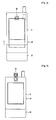
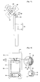
- FIG. 6 shows a conventional slide type mobile phone where upper and lower cases 11 and 12 of a main body case 10 are designed to slide up and down and a camera 20 is installed on the upper case 11 to be capable of rotating about a hinge portion.
- the slide type camera illustrated in FIGs. 4 and 5 it can provide the self-camera function. However, when it is in a slide-up state, it cannot provide the self-camera function.
- the slide type camera depicted in FIG. 6 since the camera module is one-sided due to the hinge structure, the object focusing is also one-sided during the self-photographing.
- the camera is generally mounted on the front, rear, or top of the main body.
- these structures make it difficult to accurately adjust the focus when the user takes a picture.
- EP 1 548 300 A1 discloses the hinge apparatus which comprises: a hollow-shaped first rotating shaft which can be pivotably moved; a second rotating shaft which is intersected with this first rotating shaft in a pivotable manner; a guide shaft which is provided inside the first rotating shaft and guides a cam mounted on the second rotating shaft at a predetermined position; a first casing member which is mounted on the first rotating shaft in an integral manner; a second casing member which is mounted on the first rotating shaft in an integral manner; and both a front cover and a rear cover, which cover both the first rotating shaft and the second rotating shaft.
- the front cover and the second cover are fixed on the first rotating shaft by a fastening screw.
- EP 1 467 538 A2 discloses a rotary type hinge device which comprises: a first hinge housing coupled to the terminal body to rotate about the first rotation axis; a main shaft having its one end fixed to the inner peripheral surface of the first hinge housing and the other end thereof protruding outwardly from one side of the first hinge housing; and a second hinge housing rotatably coupled to the other end of the main shaft protruded outwardly from the first hinge housing and adapted to rotate about the second rotation axis.
- the head portion 200 is capable of rotating in front and rear directions of the main body case 100 about a center of the first hinge portion 310 by a predetermined rotational angle and capable of rotating in left and right direction of the main body case about the second hinge portion 320 by a predetermined rotational angle.
- the first hinge portion 310 is coupled to be capable of relatively sliding in the longitudinal direction of the main body case 100.
- the hinge coupling portion 122 of the sliding case 120 is provided with the sliding groove 123 formed in the longitudinal direction to slidably receive the fixing portion 311 of the fist hinge portion 310.
- the user slides up the slide case 120 with respect to the main case 110 using a slide mechanism.
- the user can rotate the head portion 200 with the camera module 210 about the hinge portion 300 in the left, right and front and rear directions according to the scene he/she intends to take.
- the user can carry and keep the portable terminal in a state where the first hinge portion 310 slides down into the main body case 100. That is, the user can carry and keep the portable terminal in a state where the head portion 200 closely contacts the main body case 100.
- a slide type portable terminal is exampled.
- the present invention is not limited to this case.
- the inventive camera rotating apparatus can be applied to other types such as a folder type, a stick type and the like.
- the present invention is directed to a camera rotating apparatus of a portable terminal that substantially obviates one or more problems due to limitations and disadvantages of the related art.
- a portable terminal including: a main body of the portable terminal; a head portion having a camera module, the head portion being capable of rotating in front, rear, left and right directions with respect to the main body; and a hinge portion rotatably connecting the head portion to the main body, as defined in claim 1.
- the head portion may include a camera module and a speaker.
- the rotation of the head portion may be selectively suppressed by a hinge member.
- the hinge member may be capable of being received in or withdrawn from the main body of the portable terminal so that the head portion can closely contact the main body or be projected from the main body to be capable of rotating in an omni-direction.
- the head portion is rotatably mounted on an upper end of the main body case of the portable terminal, the self-photographic becomes possible by rotating the camera and the object focus is not one-sided.
- the speaker can be disposed on the head portion, the sound output direction can be adjusted by rotating the head portion.
- FIG. 1 is a front view of a conventional folder type mobile phone where a camera is mounted on a front portion of a main body case;
- FIG. 2 is a rear view of another conventional folder type mobile phone where a camera is mounted on an upper-rear portion of a main body case;
- FIG. 3 is a front view of still another conventional folder type mobile phone where a camera is mounted on a hinge portion of a main body case;
- FIGs. 4 and 5 are front views of a conventional slide phone where a camera is mounted on an upper end of a lower case of a main body;
- FIG. 6 is a front view of another conventional slide phone where a camera is rotatably coupled to a hinge portion formed on an upper end of an upper case of a main body;
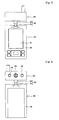
- FIGs. 7 through 9 are respectively front, rear and side views of a portable terminal having a camera rotating apparatus according to an embodiment of the present invention.
- FIGs. 10 through 12 are respectively front, side and rear views illustrating an operation of a potable terminal having a camera rotating apparatus according to an embodiment of the present invention
- FIG. 13 is an exploded perspective view of a portable terminal with a camera rotating apparatus according to the present invention.
- FIG. 14 is a perspective view of a coupling structure of a head portion of a portable terminal having a camera rotating apparatus according to an embodiment of the present invention.
- FIG. 7 shows a front portion of a portable terminal with a camera rotating apparatus according to an embodiment of the present invention.
- the portable terminal includes a main body case 100, a head portion 200 having a camera module and mounted on an upper end of the main body case 100 to be capable of rotating in an omni-direction, and a hinge portion for rotatably connecting the head portion 200 on the main body case 100.
- a main printed circuit board (PCB) (not shown) is provided in the main body case 100 to input information and control the communication.
- PCB printed circuit board
- a display 121 such as a liquid crystal display (LCD) is provided on a front surface of the upper case.
- LCD liquid crystal display
- the head portion 200 is coupled on an upper end of the slide case 120 to be capable of rotating in the omni-direction.
- the hinge portion 300 includes a first hinge portion 310 pivotally coupled to the main body case 100 and a second hinge portion 320 having a first end pivotally coupled to the first hinge portion 310 and a second end integrally coupled to the head portion 200.
- the head portion 200 is capable of rotating in front and rear directions of the main body case 100 about a center of the first hinge portion 310 by a predetermined rotational angle and capable of rotating in left and right direction of the main body case about the second hinge portion 320 by a predetermined rotational angle.
- the hinge portion 300 is elevated upward from the slide case 120. Therefore, the head portion 200 is designed to be spaced apart from the upper portion of the slide case 120.
- the head portion 200 having the camera module 210 is designed to be capable of rotating in the front, rear, left and right directions, the user can adjust the direction of the head portion 200 according to the scene he/she intends to take. Furthermore, since the hinge structure is symmetrically formed, the camera module is to be located on a center of the head portion. Therefore, the user can take a picture without the object focus one-sided.
- the first hinge portion 310 slides down into the main body case 100. That is, the head portion 200 closely contacts the main body case 100.
- FIG. 8 shows a rear portion of the portable terminal with the camera rotating apparatus according to the present invention.
- the main body case 100 includes a main case 110 provided with a keypad and a slide case 120 provided with a display.
- the main case 110 and the slide case 120 can be opened and closed as they slides in their longitudinal directions.
- the camera module 210 is provided on a mid-portion of the head portion 200.
- Speakers 220 are provided on the head portion 200 at the both sides of the camera module 210.
- the hinge portion 300 includes the first and second hinge portions 310 and 320.
- the user can adjust the direction of the head portion 200 according to the scene he/she intends to take.
- the camera module can be located on the center of the head portion.
- the speakers 220 are formed on the head portion 200, the sound output direction can be adjusted by rotating the head portion 200.
- FIG. 9 shows a side portion of the portable terminal with the camera rotating apparatus according to the present invention.
- the main body case 100 includes the main case 110 provided with a keypad and the slide case 120 provided with a display.
- the main case 110 and the slide case 120 can be opened and closed as they slides in their longitudinal directions.
- the head portion 200 with the camera module 210 is provided on the upper end of the slide case 120 to be capable of rotating in the omni-direction by the hinge portion 300.
- the hinge portion 300 includes the first and second hinge portions 310 and 320.
- FIG. 10 shows the front portion of the portable terminal with the camera rotating apparatus to illustrate the operation of the portable terminal.
- the main PCB (not shown) is provided in the main body case 100 to input the information and control the communication.
- the main case 110 is provided with the keypad 111 and the slide case 120 is provided at the front surface with the display 121 such as the LCD.
- the main case 110 and the slide case 120 can be opened and closed as they slides in their longitudinal directions.
- the head portion 200 is coupled to the upper end of the slide case 120 to be capable of rotating left, right, front and rear directions by the hinge portion 300 having the first and second hinge portions 310 and 320.
- FIG. 11 shows the side portion of the portable terminal with the camera rotating apparatus to illustrate the operation of the portable terminal.
- the main body case 100 includes the main case 110 and the slide case 120.
- the main case 110 and the slide case 120 can be opened and closed as they slides in their longitudinal directions.
- the head portion 200 with the camera module 210 is provided on the upper end of the slide case 120 to be capable of rotating in the omni-direction by the hinge portion 300.
- the camera module 210 and the speakers 220 are disposed on the head portion 200.
- the hinge portion 300 includes the first hinge portion 310 pivotally coupled to the main body case 100 and the second hinge portion 320 having the first end pivotally coupled to the first hinge portion 310 and the second end integrally coupled to the head portion 200.
- the head portion 200 is capable of rotating in the front and rear directions of the main body case 100 about the center of the first hinge portion 310 by a predetermined rotational angle and capable of rotating in left and right direction of the main body case about the second hinge portion 320 by a predetermined rotational angle.
- the hinge portion 300 is elevated upward from the slide case 120. Therefore, the head portion 200 is designed to be spaced apart from the upper portion of the slide case 120.
- the user slides up the slide case 120 with respect to the main case 110 using a slide mechanism.
- the user can rotate the head portion 200 with the camera module 210 about the hinge portion 300 in the left, right and front and rear directions according to the scene he/she intends to take.
- the sound output direction of the speakers 220 can be adjusted by rotating the head portion 200.
- FIG. 12 shows the rear portion of the portable terminal with the camera rotating apparatus to illustrate the operation of the portable terminal.
- the main body case 100 includes the main case 110 provided with the keypad 111 and the slide case 120 provided with the display 121.
- the main case 110 and the slide case 120 can be opened and closed as they slides in their longitudinal directions.
- the head portion 200 with the camera module 210 is provided on the upper end of the slide case 120 to be capable of rotating in the omni-direction by the hinge portion 300.
- the camera module 210 and the speakers 220 are disposed on the head portion 200.
- the hinge portion 300 includes the first hinge portion 310 pivotally coupled to the main body case 100 and the second hinge portion 320 having the first end pivotally coupled to the first hinge portion 310 and the second end integrally coupled to the head portion 200.
- the first hinge portion 310 includes a fixing portion 311 coupled to a hinge coupling portion 122 of the slide case 120 and a rotational portion 312 coupled to the slide case 120 to be capable of rotating in the front and rear directions about the fixing portion 311.
- the second hinge portion 320 is integrally coupled to a lower portion of the head portion 200 and coupled to an upper portion of the rotational portion 312 of the first hinge portion 310 to be capable of relatively rotating in the left and right directions of the main body case 100.
- the head portion 200 is capable of rotating in the front and rear directions of the main body case 100 about the center of the first hinge portion 310 by a predetermined rotational angle and capable of rotating in left and right direction of the main body case about the second hinge portion 320 by a predetermined rotational angle.
- the first hinge portion 310 is coupled to be capable of relatively sliding in a longitudinal direction of the main body case 100.
- the hinge coupling portion 122 of the sliding case 120 is provided with a sliding groove 123 formed in the longitudinal direction to slidably receive the fixing portion 311 of the fist hinge portion 310.
- the hinge portion capable of sliding in the longitudinal direction of the main body case 100 and selectively received in the main body case 100 is locked or unlocked from the main body case 100 by fixing and projection and groove 124 and 313 respectively formed on the main body case 100 and the first hinge portion 310. That is, by the fixing projection 124 formed on the inner wall of the sliding groove 123 and the fixing groove 313, which is formed on an side end of the fixing portion 311 of the first hinge portion 310 and in which the fixing projection 124 is to be hooked, the withdrawn and received state of the hinge portion 300 can be fixed.
- the hinge portion 300 When the hinge portion 300 is received in the hinge coupling portion 122, the rotation of the first hinge portion 310 in the front and rear directions may be suppressed but the second hinge portion 320 may be still capable of rotating in the left and right directions.
- the hinge portion 300 When the hinge portion 300 is withdrawn from the hinge coupling portion 122, the head portion 200 is projected from the main body case, in a state of which the head portion 200 can rotate in the left, right, front and rear directions by the first and second hinge portions 310 and 320.
- FIG. 13 is an exploded perspective view of the portable terminal with the camera rotating apparatus according to the present invention.
- the portable terminal includes the main body case 100, the head portion 200 having a camera module 210 and mounted on an upper end of the main body case 100 to be capable of rotating in an omni-direction, and the hinge portion for rotatably connecting the head portion 200 on the main body case 100.
- the main PCB (not shown) is provided in the main body case 100 to input information and control the communication.
- the main body case 100 includes the main case 110 provided with the keypad 111 and the slide case 120 provided with the display 121.
- the main case 110 and the slide case 120 can be opened and closed as they slides in their longitudinal directions by the sliding assembly 400.
- the sliding assembly 400 includes upper and lower plates 410 and 420 and a spring (not shown) interposed between the upper and lower plates 410 and 420.
- the upper plate 410 is slidably coupled to the lower plate 420.
- the lower plate 420 is fixed on the main case 110 and the upper plate 410 is fixed on the slide case 120.
- the camera module 210 is provided on the mid-portion of the case 201 of the head portion 200 and the speakers 220 are provided on the case 201 at the both sides of the camera module 210.
- the hinge portion 300 includes the first hinge portion 310 pivotally coupled to the main body case 100 and the second hinge portion 320 having the first end pivotally coupled to the first hinge portion 310 and the second end integrally coupled to the head portion 200.
- the first hinge portion 310 includes the fixing portion 311 coupled to the hinge coupling portion 122 of the slide case 120 and the rotational portion 312 coupled to the slide case 120 to be capable of rotating in the front and rear directions about the fixing portion 311.
- the second hinge portion 320 is integrally coupled to the lower portion of the head portion 200 and coupled to the upper portion of the rotational portion 312 of the first hinge portion 310 to be capable of relatively rotating in the left and right directions of the main body case 100.
- the hinge portion 300 is elevated upward from the slide case 120. Therefore, the head portion 200 is designed to be spaced apart from the upper portion of the slide case 120.
- the first hinge portion 310 is coupled to be capable of relatively sliding in the longitudinal direction of the main body case 100.
- the hinge coupling portion 122 of the sliding case 120 is provided with the sliding groove 123 formed in the longitudinal direction to slidably receive the fixing portion 311 of the fist hinge portion 310.
- the mechanical constitution and operation for receiving the hinge portion 300 in the hinge coupling portion 122 and for projecting the hinge portion 300 out of the hinge coupling portion 122 will refer to FIG. 12 .
- the user slides up the slide case 120 with respect to the main case 110 using a slide mechanism.
- the user can rotate the head portion 200 with the camera module 210 about the hinge portion 300 in the left, right and front and rear directions according to the scene he/she intends to take.
- the camera module can be located on the center of the head portion.
- the user can conveniently solve the one-side problem of the object focus.
- the sound output direction of the speakers 220 can be adjusted by rotating the head portion 200.
- the user can carry and keep the portable terminal in a state where the first hinge portion 310 slides down into the main body case 100. That is, the user can carry and keep the portable terminal in a state where the head portion 200 closely contacts the main body case 100.
- FIG. 14 shows a coupling structure of the head portion of the portable terminal with the camera rotating apparatus according to the present invention.
- the slide case 120 of the main body case 100 includes the upper and lower cases 120a and 120b.
- the display 121 is formed on the front surface of the upper case 120a.
- the head portion 200 is coupled to the upper end of the slide case 120 to be capable of rotating in the left, right, front and rear directions by the hinge portion 300.
- the camera module 210 is provided on the mid-portion of the case 201 of the head portion 200 and the speakers 220 are provided on the case 201 at the both sides of the camera module 210.
- the hinge portion 300 includes the first and second hinge portions 310 and 320.
- the first hinge portion 310 includes a fixing portion 311 coupled to a hinge coupling portion 122 of the slide case 120 and a rotational portion 312 coupled to the slide case 120 to be capable of rotating in the front and rear directions about the fixing portion 311.
- the second hinge portion 320 is integrally coupled to the lower portion of the head portion 200 and coupled to the upper portion of the rotational portion 312 of the first hinge portion 310 to be capable of relatively rotating in the left and right directions of the main body case 100.
Landscapes
- Engineering & Computer Science (AREA)
- Signal Processing (AREA)
- Physics & Mathematics (AREA)
- General Physics & Mathematics (AREA)
- Computer Networks & Wireless Communication (AREA)
- Telephone Set Structure (AREA)
- Studio Devices (AREA)
- Photographic Developing Apparatuses (AREA)
- Telephone Function (AREA)
Abstract
Description
- The present invention relates to a camera rotating apparatus of a portable terminal.
- In recent years, a camera has been provided on a portable terminal such as a mobile phone.
-
FIG. 1 shows a conventional folder type mobile phone where acamera 20 is fixedly mounted on amain body case 10.FIG. 2 shows another conventional folder type mobile phone where abattery 40 is coupled to a rear portion of amain body case 10 and acamera 20 is fixedly mounted above thebattery 40 on the rear portion of themain body case 10.FIG. 3 shows still another conventional mobile phone where acamera 20 is rotatably installed on ahinge portion 30 formed on amain body case 10.FIGs. 4 and5 show a conventional slide type mobile phone where upper andlower cases main body case 10 are designed to slide up and down and acamera 20 is installed on theupper case 11.FIG. 6 shows a conventional slide type mobile phone where upper andlower cases main body case 10 are designed to slide up and down and acamera 20 is installed on theupper case 11 to be capable of rotating about a hinge portion. - For the folder type mobile phones that are depicted in
FIGs. 1 and 2 , since the cameras are fixed on the folder, they cannot provide a self-camera function. - For the rotating camera depicted in
FIG. 3 , it is inconvenient to rotate a front case of the folder. Furthermore, due to the size limitation of the hinge portion, it is difficult to mount a high definition camera module. In addition, since the camera module is one-sided in a direction due to the hinge structure, the object focusing is one-sided when the user takes a picture. - For the slide type camera illustrated in
FIGs. 4 and5 , it can provide the self-camera function. However, when it is in a slide-up state, it cannot provide the self-camera function. For the slide type camera depicted inFIG. 6 , since the camera module is one-sided due to the hinge structure, the object focusing is also one-sided during the self-photographing. - That is, in the conventional portable terminals with the camera, the camera is generally mounted on the front, rear, or top of the main body. However, these structures make it difficult to accurately adjust the focus when the user takes a picture. Furthermore, in some cases, it is difficult to take the self-photographing.
EP 1 548 300 A1 discloses the hinge apparatus which comprises: a hollow-shaped first rotating shaft which can be pivotably moved; a second rotating shaft which is intersected with this first rotating shaft in a pivotable manner; a guide shaft which is provided inside the first rotating shaft and guides a cam mounted on the second rotating shaft at a predetermined position; a first casing member which is mounted on the first rotating shaft in an integral manner; a second casing member which is mounted on the first rotating shaft in an integral manner; and both a front cover and a rear cover, which cover both the first rotating shaft and the second rotating shaft. In the hinge apparatus, the front cover and the second cover are fixed on the first rotating shaft by a fastening screw.
EP 1 467 538 A2 discloses a rotary type hinge device which comprises: a first hinge housing coupled to the terminal body to rotate about the first rotation axis; a main shaft having its one end fixed to the inner peripheral surface of the first hinge housing and the other end thereof protruding outwardly from one side of the first hinge housing; and a second hinge housing rotatably coupled to the other end of the main shaft protruded outwardly from the first hinge housing and adapted to rotate about the second rotation axis. - The
head portion 200 is capable of rotating in front and rear directions of themain body case 100 about a center of thefirst hinge portion 310 by a predetermined rotational angle and capable of rotating in left and right direction of the main body case about thesecond hinge portion 320 by a predetermined rotational angle. In order for thehinge 300 to be selectively received in themain body case 100, thefirst hinge portion 310 is coupled to be capable of relatively sliding in the longitudinal direction of themain body case 100. To realize this, thehinge coupling portion 122 of thesliding case 120 is provided with thesliding groove 123 formed in the longitudinal direction to slidably receive thefixing portion 311 of thefist hinge portion 310. - In order to make a phone call, the user slides up the
slide case 120 with respect to themain case 110 using a slide mechanism. In addition, the user can rotate thehead portion 200 with thecamera module 210 about thehinge portion 300 in the left, right and front and rear directions according to the scene he/she intends to take. - The user can carry and keep the portable terminal in a state where the
first hinge portion 310 slides down into themain body case 100. That is, the user can carry and keep the portable terminal in a state where thehead portion 200 closely contacts themain body case 100. - In the embodiments illustrated in conjunction with
FIGs. 7 through 14 , only a slide type portable terminal is exampled. However, the present invention is not limited to this case. For example, the inventive camera rotating apparatus can be applied to other types such as a folder type, a stick type and the like. - Accordingly, the present invention is directed to a camera rotating apparatus of a portable terminal that substantially obviates one or more problems due to limitations and disadvantages of the related art.
- It is an object of the present invention to provide a camera rotating apparatus that can allow a camera to rotate in an omni-direction with respect to a main body of the terminal.
- It is another object of the present invention to provide a camera rotating apparatus that can accurately adjust an object focus by allowing a head portion with a camera module to be adjusted in an omni-direction.
- Additional advantages, objects, and features of the invention will be set forth in part in the description which follows and in part will become apparent to those having ordinary skill in the art upon examination of the following or may be learned from practice of the invention. The objectives and other advantages of the invention may be realized and attained by the structure particularly selected out in the written description and claims hereof as well as the appended drawings.
- To achieve these objects and other advantages and in accordance with the purpose of the invention, as embodied and broadly described herein, there is provided a portable terminal, including: a main body of the portable terminal; a head portion having a camera module, the head portion being capable of rotating in front, rear, left and right directions with respect to the main body; and a hinge portion rotatably connecting the head portion to the main body, as defined in claim 1.
- The head portion may include a camera module and a speaker.
- The rotation of the head portion may be selectively suppressed by a hinge member.
- The hinge member may be capable of being received in or withdrawn from the main body of the portable terminal so that the head portion can closely contact the main body or be projected from the main body to be capable of rotating in an omni-direction.
- It is to be understood that both the foregoing general description and the following detailed description of the present invention are exemplary and explanatory and are intended to provide further explanation of the invention as claimed.
- According to the camera rotating apparatus of the portable terminal of the present invention, since the head portion is rotatably mounted on an upper end of the main body case of the portable terminal, the self-photographic becomes possible by rotating the camera and the object focus is not one-sided. In addition, since the speaker can be disposed on the head portion, the sound output direction can be adjusted by rotating the head portion.
- The accompanying drawings, which are included to provide a further understanding of the invention and are incorporated in and constitute a part of this application, illustrate embodiment(s) of the invention and together with the description serve to explain the principle of the invention. In the drawings:
-
FIG. 1 is a front view of a conventional folder type mobile phone where a camera is mounted on a front portion of a main body case; -
FIG. 2 is a rear view of another conventional folder type mobile phone where a camera is mounted on an upper-rear portion of a main body case; -
FIG. 3 is a front view of still another conventional folder type mobile phone where a camera is mounted on a hinge portion of a main body case; -
FIGs. 4 and5 are front views of a conventional slide phone where a camera is mounted on an upper end of a lower case of a main body; -
FIG. 6 is a front view of another conventional slide phone where a camera is rotatably coupled to a hinge portion formed on an upper end of an upper case of a main body; -
FIGs. 7 through 9 are respectively front, rear and side views of a portable terminal having a camera rotating apparatus according to an embodiment of the present invention; -
FIGs. 10 through 12 are respectively front, side and rear views illustrating an operation of a potable terminal having a camera rotating apparatus according to an embodiment of the present invention; -
FIG. 13 is an exploded perspective view of a portable terminal with a camera rotating apparatus according to the present invention; and -
FIG. 14 is a perspective view of a coupling structure of a head portion of a portable terminal having a camera rotating apparatus according to an embodiment of the present invention. - Reference will now be made in detail to the preferred embodiments of the present invention, examples of which are illustrated in the accompanying drawings. Wherever possible, the same reference numbers will be used throughout the drawings to refer to the same or like parts.
-
FIG. 7 shows a front portion of a portable terminal with a camera rotating apparatus according to an embodiment of the present invention. The portable terminal includes amain body case 100, ahead portion 200 having a camera module and mounted on an upper end of themain body case 100 to be capable of rotating in an omni-direction, and a hinge portion for rotatably connecting thehead portion 200 on themain body case 100. - A main printed circuit board (PCB) (not shown) is provided in the
main body case 100 to input information and control the communication. There is aslide case 120 having an upper case. Adisplay 121 such as a liquid crystal display (LCD) is provided on a front surface of the upper case. - The
head portion 200 is coupled on an upper end of theslide case 120 to be capable of rotating in the omni-direction. Thehinge portion 300 includes afirst hinge portion 310 pivotally coupled to themain body case 100 and asecond hinge portion 320 having a first end pivotally coupled to thefirst hinge portion 310 and a second end integrally coupled to thehead portion 200. - The
head portion 200 is capable of rotating in front and rear directions of themain body case 100 about a center of thefirst hinge portion 310 by a predetermined rotational angle and capable of rotating in left and right direction of the main body case about thesecond hinge portion 320 by a predetermined rotational angle. - In order to prevent a lower portion of the
head portion 200 from interfering an upper portion of theslide case 120 when thehead portion 200 rotates in the front and rear directions of themain body case 100 about thefirst hinge portion 310, thehinge portion 300 is elevated upward from theslide case 120. Therefore, thehead portion 200 is designed to be spaced apart from the upper portion of theslide case 120. - Since the
head portion 200 having thecamera module 210 is designed to be capable of rotating in the front, rear, left and right directions, the user can adjust the direction of thehead portion 200 according to the scene he/she intends to take. Furthermore, since the hinge structure is symmetrically formed, the camera module is to be located on a center of the head portion. Therefore, the user can take a picture without the object focus one-sided. - When the user intends to carry or keep the portable terminal, the
first hinge portion 310 slides down into themain body case 100. That is, thehead portion 200 closely contacts themain body case 100. -
FIG. 8 shows a rear portion of the portable terminal with the camera rotating apparatus according to the present invention. Themain body case 100 includes amain case 110 provided with a keypad and aslide case 120 provided with a display. Themain case 110 and theslide case 120 can be opened and closed as they slides in their longitudinal directions. Thecamera module 210 is provided on a mid-portion of thehead portion 200.Speakers 220 are provided on thehead portion 200 at the both sides of thecamera module 210. As described above, thehinge portion 300 includes the first andsecond hinge portions - When the user takes a picture, the user can adjust the direction of the
head portion 200 according to the scene he/she intends to take. By the symmetrical hinge structure illustrated inFIGs. 7 and 8 , the camera module can be located on the center of the head portion. In addition, since thespeakers 220 are formed on thehead portion 200, the sound output direction can be adjusted by rotating thehead portion 200. -
FIG. 9 shows a side portion of the portable terminal with the camera rotating apparatus according to the present invention. - As described above, the
main body case 100 includes themain case 110 provided with a keypad and theslide case 120 provided with a display. Themain case 110 and theslide case 120 can be opened and closed as they slides in their longitudinal directions. Thehead portion 200 with thecamera module 210 is provided on the upper end of theslide case 120 to be capable of rotating in the omni-direction by thehinge portion 300. As described above, thehinge portion 300 includes the first andsecond hinge portions -
FIG. 10 shows the front portion of the portable terminal with the camera rotating apparatus to illustrate the operation of the portable terminal. - The main PCB (not shown) is provided in the
main body case 100 to input the information and control the communication. Themain case 110 is provided with thekeypad 111 and theslide case 120 is provided at the front surface with thedisplay 121 such as the LCD. Themain case 110 and theslide case 120 can be opened and closed as they slides in their longitudinal directions. - The
head portion 200 is coupled to the upper end of theslide case 120 to be capable of rotating left, right, front and rear directions by thehinge portion 300 having the first andsecond hinge portions -
FIG. 11 shows the side portion of the portable terminal with the camera rotating apparatus to illustrate the operation of the portable terminal. - As described above, the
main body case 100 includes themain case 110 and theslide case 120. Themain case 110 and theslide case 120 can be opened and closed as they slides in their longitudinal directions. - The
head portion 200 with thecamera module 210 is provided on the upper end of theslide case 120 to be capable of rotating in the omni-direction by thehinge portion 300. Thecamera module 210 and thespeakers 220 are disposed on thehead portion 200. - The
hinge portion 300 includes thefirst hinge portion 310 pivotally coupled to themain body case 100 and thesecond hinge portion 320 having the first end pivotally coupled to thefirst hinge portion 310 and the second end integrally coupled to thehead portion 200. - As shown in
FIG. 11 , thehead portion 200 is capable of rotating in the front and rear directions of themain body case 100 about the center of thefirst hinge portion 310 by a predetermined rotational angle and capable of rotating in left and right direction of the main body case about thesecond hinge portion 320 by a predetermined rotational angle. - In order to prevent the lower portion of the
head portion 200 from interfering an upper portion of theslide case 120 when thehead portion 200 rotates in the front and rear directions of themain body case 100 about thefirst hinge portion 310, thehinge portion 300 is elevated upward from theslide case 120. Therefore, thehead portion 200 is designed to be spaced apart from the upper portion of theslide case 120. - In order to make a phone call, illustrated in
FIGs. 10 and11 , the user slides up theslide case 120 with respect to themain case 110 using a slide mechanism. In addition, the user can rotate thehead portion 200 with thecamera module 210 about thehinge portion 300 in the left, right and front and rear directions according to the scene he/she intends to take. Furthermore, the sound output direction of thespeakers 220 can be adjusted by rotating thehead portion 200. -
FIG. 12 shows the rear portion of the portable terminal with the camera rotating apparatus to illustrate the operation of the portable terminal. - As described above, the
main body case 100 includes themain case 110 provided with thekeypad 111 and theslide case 120 provided with thedisplay 121. Themain case 110 and theslide case 120 can be opened and closed as they slides in their longitudinal directions. Thehead portion 200 with thecamera module 210 is provided on the upper end of theslide case 120 to be capable of rotating in the omni-direction by thehinge portion 300. Thecamera module 210 and thespeakers 220 are disposed on thehead portion 200. - The
hinge portion 300 includes thefirst hinge portion 310 pivotally coupled to themain body case 100 and thesecond hinge portion 320 having the first end pivotally coupled to thefirst hinge portion 310 and the second end integrally coupled to thehead portion 200. - The
first hinge portion 310 includes a fixingportion 311 coupled to ahinge coupling portion 122 of theslide case 120 and arotational portion 312 coupled to theslide case 120 to be capable of rotating in the front and rear directions about the fixingportion 311. Thesecond hinge portion 320 is integrally coupled to a lower portion of thehead portion 200 and coupled to an upper portion of therotational portion 312 of thefirst hinge portion 310 to be capable of relatively rotating in the left and right directions of themain body case 100. - By the above-described structure, the
head portion 200 is capable of rotating in the front and rear directions of themain body case 100 about the center of thefirst hinge portion 310 by a predetermined rotational angle and capable of rotating in left and right direction of the main body case about thesecond hinge portion 320 by a predetermined rotational angle. - In order for the
hinge 300 to be selectively received in themain body case 100, thefirst hinge portion 310 is coupled to be capable of relatively sliding in a longitudinal direction of themain body case 100. To realize this, thehinge coupling portion 122 of the slidingcase 120 is provided with a slidinggroove 123 formed in the longitudinal direction to slidably receive the fixingportion 311 of thefist hinge portion 310. - The hinge portion capable of sliding in the longitudinal direction of the
main body case 100 and selectively received in themain body case 100 is locked or unlocked from themain body case 100 by fixing and projection and groove 124 and 313 respectively formed on themain body case 100 and thefirst hinge portion 310. That is, by the fixingprojection 124 formed on the inner wall of the slidinggroove 123 and the fixinggroove 313, which is formed on an side end of the fixingportion 311 of thefirst hinge portion 310 and in which the fixingprojection 124 is to be hooked, the withdrawn and received state of thehinge portion 300 can be fixed. When thehinge portion 300 is received in thehinge coupling portion 122, the rotation of thefirst hinge portion 310 in the front and rear directions may be suppressed but thesecond hinge portion 320 may be still capable of rotating in the left and right directions. When thehinge portion 300 is withdrawn from thehinge coupling portion 122, thehead portion 200 is projected from the main body case, in a state of which thehead portion 200 can rotate in the left, right, front and rear directions by the first andsecond hinge portions -
FIG. 13 is an exploded perspective view of the portable terminal with the camera rotating apparatus according to the present invention. - As described above, the portable terminal includes the
main body case 100, thehead portion 200 having acamera module 210 and mounted on an upper end of themain body case 100 to be capable of rotating in an omni-direction, and the hinge portion for rotatably connecting thehead portion 200 on themain body case 100. - The main PCB (not shown) is provided in the
main body case 100 to input information and control the communication. Themain body case 100 includes themain case 110 provided with thekeypad 111 and theslide case 120 provided with thedisplay 121. Themain case 110 and theslide case 120 can be opened and closed as they slides in their longitudinal directions by the slidingassembly 400. The slidingassembly 400 includes upper andlower plates lower plates upper plate 410 is slidably coupled to thelower plate 420. Thelower plate 420 is fixed on themain case 110 and theupper plate 410 is fixed on theslide case 120. - The
camera module 210 is provided on the mid-portion of thecase 201 of thehead portion 200 and thespeakers 220 are provided on thecase 201 at the both sides of thecamera module 210. - The
hinge portion 300 includes thefirst hinge portion 310 pivotally coupled to themain body case 100 and thesecond hinge portion 320 having the first end pivotally coupled to thefirst hinge portion 310 and the second end integrally coupled to thehead portion 200. - The
first hinge portion 310 includes the fixingportion 311 coupled to thehinge coupling portion 122 of theslide case 120 and therotational portion 312 coupled to theslide case 120 to be capable of rotating in the front and rear directions about the fixingportion 311. Thesecond hinge portion 320 is integrally coupled to the lower portion of thehead portion 200 and coupled to the upper portion of therotational portion 312 of thefirst hinge portion 310 to be capable of relatively rotating in the left and right directions of themain body case 100. - In order to prevent the lower portion of the
head portion 200 from interfering an upper portion of theslide case 120 when thehead portion 200 rotates in the front and rear directions of themain body case 100 about thefirst hinge portion 310, thehinge portion 300 is elevated upward from theslide case 120. Therefore, thehead portion 200 is designed to be spaced apart from the upper portion of theslide case 120. - In order for the
hinge portion 300 to be selectively received in themain body case 100, thefirst hinge portion 310 is coupled to be capable of relatively sliding in the longitudinal direction of themain body case 100. To realize this, thehinge coupling portion 122 of the slidingcase 120 is provided with the slidinggroove 123 formed in the longitudinal direction to slidably receive the fixingportion 311 of thefist hinge portion 310. - The mechanical constitution and operation for receiving the
hinge portion 300 in thehinge coupling portion 122 and for projecting thehinge portion 300 out of thehinge coupling portion 122 will refer toFIG. 12 . - By the above-described structure, in order to make a phone call, the user slides up the
slide case 120 with respect to themain case 110 using a slide mechanism. In addition, the user can rotate thehead portion 200 with thecamera module 210 about thehinge portion 300 in the left, right and front and rear directions according to the scene he/she intends to take. In addition, since the hinge structure is symmetrically formed, the camera module can be located on the center of the head portion. Thus, the user can conveniently solve the one-side problem of the object focus. Furthermore, the sound output direction of thespeakers 220 can be adjusted by rotating thehead portion 200. - The user can carry and keep the portable terminal in a state where the
first hinge portion 310 slides down into themain body case 100. That is, the user can carry and keep the portable terminal in a state where thehead portion 200 closely contacts themain body case 100. -
FIG. 14 shows a coupling structure of the head portion of the portable terminal with the camera rotating apparatus according to the present invention. - The
slide case 120 of themain body case 100 includes the upper andlower cases display 121 is formed on the front surface of theupper case 120a. Thehead portion 200 is coupled to the upper end of theslide case 120 to be capable of rotating in the left, right, front and rear directions by thehinge portion 300. Thecamera module 210 is provided on the mid-portion of thecase 201 of thehead portion 200 and thespeakers 220 are provided on thecase 201 at the both sides of thecamera module 210. - The
hinge portion 300 includes the first andsecond hinge portions first hinge portion 310 includes a fixingportion 311 coupled to ahinge coupling portion 122 of theslide case 120 and arotational portion 312 coupled to theslide case 120 to be capable of rotating in the front and rear directions about the fixingportion 311. Thesecond hinge portion 320 is integrally coupled to the lower portion of thehead portion 200 and coupled to the upper portion of therotational portion 312 of thefirst hinge portion 310 to be capable of relatively rotating in the left and right directions of themain body case 100.
Claims (13)
- A portable terminal, comprising:a main body (100) of the portable terminal;a head portion (200) comprising a camera module (210), the head portion (200) being capable of rotating in front, rear, left and right directions with respect to the main body (100); anda hinge portion (300) rotatably connecting the head portion (200) to the main body (100), characterised in that:the hinge portion (300) is designed to slide down so as to be received in or to slide up so as to be withdrawn from the main body (100).
- The portable terminal according to claims 1, wherein the main body (100) is a slide type.
- The portable terminal according to claims 1, wherein the head portion (200) comprises a speaker (220).
- The portable terminal according to claims 1, wherein the head portion (200) is selectively suppressed in its free rotation with respect to the main body (100).
- The portable terminal according to claims 1. wherein the head portion (200) is selectively suppressed in its rotation in the front and rear directions with respect to the main body (100) but not suppressed in its rotation in the left and right directions
- The portable terminal according to claim 1, wherein the hinge portion (300) comprises a first hinge member (310) for rotating the head portion (200) in the front and rear directions and a second hinge member (320) for rotating the head portion (200) in the left and right directions.
- The portable terminal according to claim 1, wherein the hinge portion (300) comprises a fixing member (311) for fixing its current positions when it is received in or withdraw from the main body (100).
- The portable terminal according to claim 6 further comprising:a hinge coupling member (122) for selectively suppressing the rotation of the head portion (200) by allowing the first and second hinge members (310, 320) to be received in or withdrawn from the main body (100).
- The portable according to claim 6, wherein the second hinge member (320) is designed to couple the first hinge member (310) to the head portion (200).
- The portable terminal according to claim 8, wherein the hinge coupling portion (122) is provided with a sliding groove (123) formed in the longitudinal direction to slidably receive the first hinge member (310).
- The portable terminal according to claim 10, wherein the sliding groove (123) is provided with a plurality of fixing projections (124) and the first hinge member (310) is provided with a groove (313).
- The portable terminal according to claim 8, wherein the rotation of the first hinge member (310) is suppressed when the hinge portion (300) is received in the hinge coupling member (122) and is not suppressed when the hinge portion (300) is withdrawn from the hinge coupling member (122).
- The portable terminal according to claim 6, wherein in a position where the rotation of the first hinge member (310) is suppressed, the rotation of the second hinge member (320) is not suppressed.
Applications Claiming Priority (2)
| Application Number | Priority Date | Filing Date | Title |
|---|---|---|---|
| KR1020040086365A KR100652570B1 (en) | 2004-10-27 | 2004-10-27 | Camera swivel apparatus for portable terminal |
| PCT/KR2005/003545 WO2006046818A1 (en) | 2004-10-27 | 2005-10-24 | Camera rotating apparatus of portable terminal |
Publications (3)
| Publication Number | Publication Date |
|---|---|
| EP1805903A1 EP1805903A1 (en) | 2007-07-11 |
| EP1805903A4 EP1805903A4 (en) | 2009-01-14 |
| EP1805903B1 true EP1805903B1 (en) | 2009-12-02 |
Family
ID=36206288
Family Applications (1)
| Application Number | Title | Priority Date | Filing Date |
|---|---|---|---|
| EP05817634A Not-in-force EP1805903B1 (en) | 2004-10-27 | 2005-10-24 | Camera rotating apparatus of portable terminal |
Country Status (7)
| Country | Link |
|---|---|
| US (1) | US7450841B2 (en) |
| EP (1) | EP1805903B1 (en) |
| KR (1) | KR100652570B1 (en) |
| CN (1) | CN101073207B (en) |
| AT (1) | ATE450932T1 (en) |
| DE (1) | DE602005018090D1 (en) |
| WO (1) | WO2006046818A1 (en) |
Families Citing this family (19)
| Publication number | Priority date | Publication date | Assignee | Title |
|---|---|---|---|---|
| US7580625B2 (en) * | 2006-05-24 | 2009-08-25 | Nokia Corporation | Handheld electronic device |
| KR100810267B1 (en) * | 2006-12-14 | 2008-03-06 | 삼성전자주식회사 | Sliding type portable terminal |
| TW200830156A (en) * | 2007-01-11 | 2008-07-16 | Primax Electronics Ltd | Twisted mouse |
| US8593570B2 (en) | 2008-11-07 | 2013-11-26 | Looxcie, Inc. | Video recording camera headset |
| US8526779B2 (en) | 2008-11-07 | 2013-09-03 | Looxcie, Inc. | Creating and editing video recorded by a hands-free video recording device |
| TWI378368B (en) * | 2008-11-26 | 2012-12-01 | Primax Electronics Ltd | Slim mouse with mode changing function |
| TWI432246B (en) * | 2008-12-12 | 2014-04-01 | Primax Electronics Ltd | Shape changable gaming controller |
| US20100182486A1 (en) * | 2009-01-19 | 2010-07-22 | Backer Chou | Portable Image Acquisitioner with Micro Objective Lens |
| CN101957551B (en) * | 2009-07-16 | 2013-11-20 | 鸿富锦精密工业(深圳)有限公司 | Portable apparatus |
| US8737803B2 (en) | 2011-05-27 | 2014-05-27 | Looxcie, Inc. | Method and apparatus for storing and streaming audiovisual content |
| US9288471B1 (en) * | 2013-02-28 | 2016-03-15 | Amazon Technologies, Inc. | Rotatable imaging assembly for providing multiple fields of view |
| CN105988519A (en) * | 2015-02-16 | 2016-10-05 | 联想(北京)有限公司 | Electronic device |
| CN104965567B (en) * | 2015-06-19 | 2019-04-26 | 联想(北京)有限公司 | Electronic equipment |
| US20190260863A1 (en) * | 2016-08-30 | 2019-08-22 | Xleap, Inc. | Information processing terminal |
| CN207910858U (en) * | 2018-02-09 | 2018-09-25 | 广东欧珀移动通信有限公司 | Mobile phone |
| CN207926663U (en) | 2018-02-09 | 2018-09-28 | 广东欧珀移动通信有限公司 | Mobile terminal |
| CN108600449B (en) * | 2018-04-23 | 2020-12-29 | 京东方科技集团股份有限公司 | Display device |
| CN109218591A (en) * | 2018-11-19 | 2019-01-15 | 维沃移动通信(杭州)有限公司 | A kind of panorama shooting method and mobile terminal |
| KR102106296B1 (en) * | 2018-11-29 | 2020-05-04 | 삼성전자주식회사 | Electric device including camera and operating method thereof |
Family Cites Families (15)
| Publication number | Priority date | Publication date | Assignee | Title |
|---|---|---|---|---|
| US6192257B1 (en) * | 1998-03-31 | 2001-02-20 | Lucent Technologies Inc. | Wireless communication terminal having video image capability |
| KR100584411B1 (en) * | 1999-07-22 | 2006-05-26 | 삼성전자주식회사 | Lens module of mobile phone |
| JP3546784B2 (en) * | 1999-12-14 | 2004-07-28 | 日本電気株式会社 | Mobile device |
| KR20010065800A (en) * | 1999-12-30 | 2001-07-11 | 윤종용 | Camera lens mounting device of folder type mobile phone |
| JP2002050999A (en) * | 2000-08-01 | 2002-02-15 | Sony Corp | Portable telephone system having camera function |
| KR20030019979A (en) * | 2001-08-28 | 2003-03-08 | 금호산업 주식회사 | Gum Chafer Compound for Tire |
| US7773957B2 (en) * | 2002-07-22 | 2010-08-10 | Samsung Electronics Co., Ltd | Mobile communication terminal with rotational display unit |
| JP3941933B2 (en) | 2002-08-26 | 2007-07-11 | 松下電器産業株式会社 | Opening and closing communication terminal and hinge device |
| KR100810300B1 (en) * | 2002-10-15 | 2008-03-06 | 삼성전자주식회사 | Portable communication device |
| KR100490356B1 (en) * | 2003-01-20 | 2005-05-17 | 삼성전자주식회사 | Rotary type hinge device for portable wireless terminal |
| KR20040072384A (en) * | 2003-02-12 | 2004-08-18 | 주식회사 팬택 | Mobile terminal having replaceable external apparatus |
| KR100463777B1 (en) * | 2003-03-11 | 2004-12-29 | 삼성전자주식회사 | Bar type portable wireless terminal and rotary type hinge device thereof |
| KR100959729B1 (en) * | 2003-03-15 | 2010-05-25 | 엘지전자 주식회사 | Folder type mobile device |
| JP4187068B2 (en) * | 2003-03-26 | 2008-11-26 | 京セラ株式会社 | Foldable mobile terminal |
| KR100513015B1 (en) | 2003-04-08 | 2005-09-05 | 삼성전자주식회사 | Rotary type hinge device for portable wireless terminal |
-
2004
- 2004-10-27 KR KR1020040086365A patent/KR100652570B1/en not_active IP Right Cessation
-
2005
- 2005-10-24 CN CN2005800368563A patent/CN101073207B/en not_active Expired - Fee Related
- 2005-10-24 AT AT05817634T patent/ATE450932T1/en not_active IP Right Cessation
- 2005-10-24 WO PCT/KR2005/003545 patent/WO2006046818A1/en active Application Filing
- 2005-10-24 DE DE602005018090T patent/DE602005018090D1/en active Active
- 2005-10-24 EP EP05817634A patent/EP1805903B1/en not_active Not-in-force
- 2005-10-25 US US11/258,774 patent/US7450841B2/en not_active Expired - Fee Related
Also Published As
| Publication number | Publication date |
|---|---|
| EP1805903A4 (en) | 2009-01-14 |
| CN101073207B (en) | 2010-12-15 |
| ATE450932T1 (en) | 2009-12-15 |
| DE602005018090D1 (en) | 2010-01-14 |
| WO2006046818A1 (en) | 2006-05-04 |
| US20060088310A1 (en) | 2006-04-27 |
| EP1805903A1 (en) | 2007-07-11 |
| KR100652570B1 (en) | 2006-12-07 |
| KR20060037182A (en) | 2006-05-03 |
| CN101073207A (en) | 2007-11-14 |
| US7450841B2 (en) | 2008-11-11 |
Similar Documents
| Publication | Publication Date | Title |
|---|---|---|
| EP1805903B1 (en) | Camera rotating apparatus of portable terminal | |
| EP1530346B1 (en) | Mobile phone having rotation type display | |
| KR100617675B1 (en) | Portable phone with rotational display unit and hinge device thereof | |
| EP1898606B1 (en) | Hinge device having a plurality of axes for a portable terminal and a connection member having the plurality of axes | |
| US7865151B2 (en) | Swing hinge device for mobile terminal | |
| KR100842529B1 (en) | Portable terminal with hinge apparatus | |
| KR100459543B1 (en) | Camera lens module and portable wireless terminal therewith | |
| US20040203535A1 (en) | Mobile phone having a rotational camera lens housing | |
| US20050261041A1 (en) | Hinge apparatus for mobile communication terminals | |
| US7567283B2 (en) | Rotary camera for mobile communication device | |
| JP2004108581A (en) | Hinge device of portable radio terminal | |
| US7440782B2 (en) | Hinge device for a display for rotation type mobile phone | |
| JP2006042396A (en) | Portable phone with camera | |
| KR20050053908A (en) | Camera lens assembly for portable terminal | |
| KR100689378B1 (en) | Hinge device for portable terminal | |
| US20060268142A1 (en) | Portable terminal having camera lens assembly | |
| KR100703512B1 (en) | Camera lens assembly for portable terminal | |
| EP1484921B1 (en) | Camera lens assembly for a portable terminal | |
| EP1511312B1 (en) | Cameralens assembly for portable wireless terminals | |
| KR101126428B1 (en) | Dual axis hinge device for portable terminal | |
| KR100536395B1 (en) | Folder type mobile communication terminal having camera | |
| KR100790169B1 (en) | Swing hinge apparatus for portable terminal | |
| KR100467847B1 (en) | Flip Type Mobile Phone Having Camera | |
| KR20050003824A (en) | Camera apparatus in mobile phone | |
| KR20040069567A (en) | Camera angle control apparatus for mobile phone |
Legal Events
| Date | Code | Title | Description |
|---|---|---|---|
| PUAI | Public reference made under article 153(3) epc to a published international application that has entered the european phase |
Free format text: ORIGINAL CODE: 0009012 |
|
| 17P | Request for examination filed |
Effective date: 20070418 |
|
| AK | Designated contracting states |
Kind code of ref document: A1 Designated state(s): AT BE BG CH CY CZ DE DK EE ES FI FR GB GR HU IE IS IT LI LT LU LV MC NL PL PT RO SE SI SK TR |
|
| DAX | Request for extension of the european patent (deleted) | ||
| A4 | Supplementary search report drawn up and despatched |
Effective date: 20081216 |
|
| 17Q | First examination report despatched |
Effective date: 20090318 |
|
| GRAP | Despatch of communication of intention to grant a patent |
Free format text: ORIGINAL CODE: EPIDOSNIGR1 |
|
| GRAS | Grant fee paid |
Free format text: ORIGINAL CODE: EPIDOSNIGR3 |
|
| GRAA | (expected) grant |
Free format text: ORIGINAL CODE: 0009210 |
|
| AK | Designated contracting states |
Kind code of ref document: B1 Designated state(s): AT BE BG CH CY CZ DE DK EE ES FI FR GB GR HU IE IS IT LI LT LU LV MC NL PL PT RO SE SI SK TR |
|
| REG | Reference to a national code |
Ref country code: GB Ref legal event code: FG4D |
|
| REG | Reference to a national code |
Ref country code: CH Ref legal event code: EP |
|
| REG | Reference to a national code |
Ref country code: IE Ref legal event code: FG4D |
|
| REF | Corresponds to: |
Ref document number: 602005018090 Country of ref document: DE Date of ref document: 20100114 Kind code of ref document: P |
|
| REG | Reference to a national code |
Ref country code: NL Ref legal event code: VDEP Effective date: 20091202 |
|
| PG25 | Lapsed in a contracting state [announced via postgrant information from national office to epo] |
Ref country code: SE Free format text: LAPSE BECAUSE OF FAILURE TO SUBMIT A TRANSLATION OF THE DESCRIPTION OR TO PAY THE FEE WITHIN THE PRESCRIBED TIME-LIMIT Effective date: 20091202 Ref country code: LT Free format text: LAPSE BECAUSE OF FAILURE TO SUBMIT A TRANSLATION OF THE DESCRIPTION OR TO PAY THE FEE WITHIN THE PRESCRIBED TIME-LIMIT Effective date: 20091202 Ref country code: FI Free format text: LAPSE BECAUSE OF FAILURE TO SUBMIT A TRANSLATION OF THE DESCRIPTION OR TO PAY THE FEE WITHIN THE PRESCRIBED TIME-LIMIT Effective date: 20091202 |
|
| LTIE | Lt: invalidation of european patent or patent extension |
Effective date: 20091202 |
|
| PG25 | Lapsed in a contracting state [announced via postgrant information from national office to epo] |
Ref country code: CY Free format text: LAPSE BECAUSE OF FAILURE TO SUBMIT A TRANSLATION OF THE DESCRIPTION OR TO PAY THE FEE WITHIN THE PRESCRIBED TIME-LIMIT Effective date: 20091202 Ref country code: SI Free format text: LAPSE BECAUSE OF FAILURE TO SUBMIT A TRANSLATION OF THE DESCRIPTION OR TO PAY THE FEE WITHIN THE PRESCRIBED TIME-LIMIT Effective date: 20091202 Ref country code: PL Free format text: LAPSE BECAUSE OF FAILURE TO SUBMIT A TRANSLATION OF THE DESCRIPTION OR TO PAY THE FEE WITHIN THE PRESCRIBED TIME-LIMIT Effective date: 20091202 Ref country code: LV Free format text: LAPSE BECAUSE OF FAILURE TO SUBMIT A TRANSLATION OF THE DESCRIPTION OR TO PAY THE FEE WITHIN THE PRESCRIBED TIME-LIMIT Effective date: 20091202 |
|
| PG25 | Lapsed in a contracting state [announced via postgrant information from national office to epo] |
Ref country code: AT Free format text: LAPSE BECAUSE OF FAILURE TO SUBMIT A TRANSLATION OF THE DESCRIPTION OR TO PAY THE FEE WITHIN THE PRESCRIBED TIME-LIMIT Effective date: 20091202 |
|
| PG25 | Lapsed in a contracting state [announced via postgrant information from national office to epo] |
Ref country code: NL Free format text: LAPSE BECAUSE OF FAILURE TO SUBMIT A TRANSLATION OF THE DESCRIPTION OR TO PAY THE FEE WITHIN THE PRESCRIBED TIME-LIMIT Effective date: 20091202 Ref country code: ES Free format text: LAPSE BECAUSE OF FAILURE TO SUBMIT A TRANSLATION OF THE DESCRIPTION OR TO PAY THE FEE WITHIN THE PRESCRIBED TIME-LIMIT Effective date: 20100313 Ref country code: PT Free format text: LAPSE BECAUSE OF FAILURE TO SUBMIT A TRANSLATION OF THE DESCRIPTION OR TO PAY THE FEE WITHIN THE PRESCRIBED TIME-LIMIT Effective date: 20100402 Ref country code: BG Free format text: LAPSE BECAUSE OF FAILURE TO SUBMIT A TRANSLATION OF THE DESCRIPTION OR TO PAY THE FEE WITHIN THE PRESCRIBED TIME-LIMIT Effective date: 20100302 Ref country code: RO Free format text: LAPSE BECAUSE OF FAILURE TO SUBMIT A TRANSLATION OF THE DESCRIPTION OR TO PAY THE FEE WITHIN THE PRESCRIBED TIME-LIMIT Effective date: 20091202 Ref country code: IS Free format text: LAPSE BECAUSE OF FAILURE TO SUBMIT A TRANSLATION OF THE DESCRIPTION OR TO PAY THE FEE WITHIN THE PRESCRIBED TIME-LIMIT Effective date: 20100402 Ref country code: EE Free format text: LAPSE BECAUSE OF FAILURE TO SUBMIT A TRANSLATION OF THE DESCRIPTION OR TO PAY THE FEE WITHIN THE PRESCRIBED TIME-LIMIT Effective date: 20091202 |
|
| PG25 | Lapsed in a contracting state [announced via postgrant information from national office to epo] |
Ref country code: SK Free format text: LAPSE BECAUSE OF FAILURE TO SUBMIT A TRANSLATION OF THE DESCRIPTION OR TO PAY THE FEE WITHIN THE PRESCRIBED TIME-LIMIT Effective date: 20091202 Ref country code: CZ Free format text: LAPSE BECAUSE OF FAILURE TO SUBMIT A TRANSLATION OF THE DESCRIPTION OR TO PAY THE FEE WITHIN THE PRESCRIBED TIME-LIMIT Effective date: 20091202 Ref country code: BE Free format text: LAPSE BECAUSE OF FAILURE TO SUBMIT A TRANSLATION OF THE DESCRIPTION OR TO PAY THE FEE WITHIN THE PRESCRIBED TIME-LIMIT Effective date: 20091202 |
|
| PLBE | No opposition filed within time limit |
Free format text: ORIGINAL CODE: 0009261 |
|
| STAA | Information on the status of an ep patent application or granted ep patent |
Free format text: STATUS: NO OPPOSITION FILED WITHIN TIME LIMIT |
|
| PG25 | Lapsed in a contracting state [announced via postgrant information from national office to epo] |
Ref country code: GR Free format text: LAPSE BECAUSE OF FAILURE TO SUBMIT A TRANSLATION OF THE DESCRIPTION OR TO PAY THE FEE WITHIN THE PRESCRIBED TIME-LIMIT Effective date: 20100303 |
|
| 26N | No opposition filed |
Effective date: 20100903 |
|
| PG25 | Lapsed in a contracting state [announced via postgrant information from national office to epo] |
Ref country code: DK Free format text: LAPSE BECAUSE OF FAILURE TO SUBMIT A TRANSLATION OF THE DESCRIPTION OR TO PAY THE FEE WITHIN THE PRESCRIBED TIME-LIMIT Effective date: 20091202 |
|
| PG25 | Lapsed in a contracting state [announced via postgrant information from national office to epo] |
Ref country code: IT Free format text: LAPSE BECAUSE OF FAILURE TO SUBMIT A TRANSLATION OF THE DESCRIPTION OR TO PAY THE FEE WITHIN THE PRESCRIBED TIME-LIMIT Effective date: 20091202 |
|
| PG25 | Lapsed in a contracting state [announced via postgrant information from national office to epo] |
Ref country code: MC Free format text: LAPSE BECAUSE OF NON-PAYMENT OF DUE FEES Effective date: 20101031 |
|
| REG | Reference to a national code |
Ref country code: CH Ref legal event code: PL |
|
| GBPC | Gb: european patent ceased through non-payment of renewal fee |
Effective date: 20101024 |
|
| PG25 | Lapsed in a contracting state [announced via postgrant information from national office to epo] |
Ref country code: CH Free format text: LAPSE BECAUSE OF NON-PAYMENT OF DUE FEES Effective date: 20101031 Ref country code: LI Free format text: LAPSE BECAUSE OF NON-PAYMENT OF DUE FEES Effective date: 20101031 |
|
| PG25 | Lapsed in a contracting state [announced via postgrant information from national office to epo] |
Ref country code: GB Free format text: LAPSE BECAUSE OF NON-PAYMENT OF DUE FEES Effective date: 20101024 |
|
| PG25 | Lapsed in a contracting state [announced via postgrant information from national office to epo] |
Ref country code: IE Free format text: LAPSE BECAUSE OF NON-PAYMENT OF DUE FEES Effective date: 20101024 |
|
| PG25 | Lapsed in a contracting state [announced via postgrant information from national office to epo] |
Ref country code: LU Free format text: LAPSE BECAUSE OF NON-PAYMENT OF DUE FEES Effective date: 20101024 Ref country code: HU Free format text: LAPSE BECAUSE OF FAILURE TO SUBMIT A TRANSLATION OF THE DESCRIPTION OR TO PAY THE FEE WITHIN THE PRESCRIBED TIME-LIMIT Effective date: 20100603 |
|
| PG25 | Lapsed in a contracting state [announced via postgrant information from national office to epo] |
Ref country code: TR Free format text: LAPSE BECAUSE OF FAILURE TO SUBMIT A TRANSLATION OF THE DESCRIPTION OR TO PAY THE FEE WITHIN THE PRESCRIBED TIME-LIMIT Effective date: 20091202 |
|
| REG | Reference to a national code |
Ref country code: FR Ref legal event code: PLFP Year of fee payment: 12 |
|
| PGFP | Annual fee paid to national office [announced via postgrant information from national office to epo] |
Ref country code: FR Payment date: 20160912 Year of fee payment: 12 |
|
| PGFP | Annual fee paid to national office [announced via postgrant information from national office to epo] |
Ref country code: DE Payment date: 20160906 Year of fee payment: 12 |
|
| REG | Reference to a national code |
Ref country code: DE Ref legal event code: R119 Ref document number: 602005018090 Country of ref document: DE |
|
| REG | Reference to a national code |
Ref country code: FR Ref legal event code: ST Effective date: 20180629 |
|
| PG25 | Lapsed in a contracting state [announced via postgrant information from national office to epo] |
Ref country code: DE Free format text: LAPSE BECAUSE OF NON-PAYMENT OF DUE FEES Effective date: 20180501 |
|
| PG25 | Lapsed in a contracting state [announced via postgrant information from national office to epo] |
Ref country code: FR Free format text: LAPSE BECAUSE OF NON-PAYMENT OF DUE FEES Effective date: 20171031 |