CN100447614C - Image display unit and projection optical system - Google Patents
Image display unit and projection optical system Download PDFInfo
- Publication number
- CN100447614C CN100447614C CNB038226979A CN03822697A CN100447614C CN 100447614 C CN100447614 C CN 100447614C CN B038226979 A CNB038226979 A CN B038226979A CN 03822697 A CN03822697 A CN 03822697A CN 100447614 C CN100447614 C CN 100447614C
- Authority
- CN
- China
- Prior art keywords
- image
- optical system
- display device
- picture
- eyeball
- Prior art date
- Legal status (The legal status is an assumption and is not a legal conclusion. Google has not performed a legal analysis and makes no representation as to the accuracy of the status listed.)
- Expired - Fee Related
Links
Images


Classifications
-
- G—PHYSICS
- G02—OPTICS
- G02B—OPTICAL ELEMENTS, SYSTEMS OR APPARATUS
- G02B17/00—Systems with reflecting surfaces, with or without refracting elements
- G02B17/08—Catadioptric systems
- G02B17/0804—Catadioptric systems using two curved mirrors
- G02B17/0816—Catadioptric systems using two curved mirrors off-axis or unobscured systems in which not all of the mirrors share a common axis of rotational symmetry, e.g. at least one of the mirrors is warped, tilted or decentered with respect to the other elements
-
- G—PHYSICS
- G02—OPTICS
- G02B—OPTICAL ELEMENTS, SYSTEMS OR APPARATUS
- G02B13/00—Optical objectives specially designed for the purposes specified below
- G02B13/06—Panoramic objectives; So-called "sky lenses" including panoramic objectives having reflecting surfaces
-
- G—PHYSICS
- G02—OPTICS
- G02B—OPTICAL ELEMENTS, SYSTEMS OR APPARATUS
- G02B17/00—Systems with reflecting surfaces, with or without refracting elements
- G02B17/02—Catoptric systems, e.g. image erecting and reversing system
- G02B17/06—Catoptric systems, e.g. image erecting and reversing system using mirrors only, i.e. having only one curved mirror
- G02B17/0605—Catoptric systems, e.g. image erecting and reversing system using mirrors only, i.e. having only one curved mirror using two curved mirrors
- G02B17/0615—Catoptric systems, e.g. image erecting and reversing system using mirrors only, i.e. having only one curved mirror using two curved mirrors off-axis or unobscured systems in wich all of the mirrors share a common axis of rotational symmetry
-
- G—PHYSICS
- G02—OPTICS
- G02B—OPTICAL ELEMENTS, SYSTEMS OR APPARATUS
- G02B17/00—Systems with reflecting surfaces, with or without refracting elements
- G02B17/08—Catadioptric systems
-
- G—PHYSICS
- G02—OPTICS
- G02B—OPTICAL ELEMENTS, SYSTEMS OR APPARATUS
- G02B23/00—Telescopes, e.g. binoculars; Periscopes; Instruments for viewing the inside of hollow bodies; Viewfinders; Optical aiming or sighting devices
- G02B23/16—Housings; Caps; Mountings; Supports, e.g. with counterweight
- G02B23/18—Housings; Caps; Mountings; Supports, e.g. with counterweight for binocular arrangements
-
- G—PHYSICS
- G02—OPTICS
- G02B—OPTICAL ELEMENTS, SYSTEMS OR APPARATUS
- G02B27/00—Optical systems or apparatus not provided for by any of the groups G02B1/00 - G02B26/00, G02B30/00
- G02B27/01—Head-up displays
- G02B27/017—Head mounted
- G02B27/0172—Head mounted characterised by optical features
-
- G—PHYSICS
- G02—OPTICS
- G02B—OPTICAL ELEMENTS, SYSTEMS OR APPARATUS
- G02B27/00—Optical systems or apparatus not provided for by any of the groups G02B1/00 - G02B26/00, G02B30/00
- G02B27/01—Head-up displays
- G02B27/0101—Head-up displays characterised by optical features
- G02B2027/011—Head-up displays characterised by optical features comprising device for correcting geometrical aberrations, distortion
-
- G—PHYSICS
- G02—OPTICS
- G02B—OPTICAL ELEMENTS, SYSTEMS OR APPARATUS
- G02B27/00—Optical systems or apparatus not provided for by any of the groups G02B1/00 - G02B26/00, G02B30/00
- G02B27/01—Head-up displays
- G02B27/0101—Head-up displays characterised by optical features
- G02B2027/0123—Head-up displays characterised by optical features comprising devices increasing the field of view
-
- G—PHYSICS
- G02—OPTICS
- G02B—OPTICAL ELEMENTS, SYSTEMS OR APPARATUS
- G02B27/00—Optical systems or apparatus not provided for by any of the groups G02B1/00 - G02B26/00, G02B30/00
- G02B27/01—Head-up displays
- G02B27/0101—Head-up displays characterised by optical features
- G02B2027/0132—Head-up displays characterised by optical features comprising binocular systems
- G02B2027/0136—Head-up displays characterised by optical features comprising binocular systems with a single image source for both eyes
Landscapes
- Physics & Mathematics (AREA)
- General Physics & Mathematics (AREA)
- Optics & Photonics (AREA)
- Astronomy & Astrophysics (AREA)
- Lenses (AREA)
- Devices For Indicating Variable Information By Combining Individual Elements (AREA)
- Stereoscopic And Panoramic Photography (AREA)
Abstract
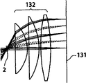
An intermediate image of an image from the LCD module 142 is deflected by reflection mirrors M 1 and M 2 via zoom automatic focus control system (g) and then is formed on diffusion glass 131 via relay lens (b) and reflection mirrors M 3 and M 4 . The LCD image is projected on the retina of eyeballs via eyepiece lens 132 by the light flux diffused at an order of +-20 degrees by diffusion glass 131 . One side of the eyepiece lens 132 close to the crystal balls 2 has an aspherical shape of a Conic surface and a Conic coefficient of the Conic surface is -1 and less. Thereby the optical system that has a viewing angle of 60 degrees and over and has a small aberration can be obtained.
Description
Technical field
The present invention relates to a kind of image display device near the eyeball use.
Background technology
There are numerous species such as televisor, personal computer, projector, video cassette recorder, mobile phone in image display device, but all there is restriction in size in the display that above-mentioned conventional images shows, in fact can't obtain the seen wide field-of-view image of human eye from display.
In addition, with regard to portable display, glasses type displayer that so-called Worn type display is arranged and the head mounted display known.
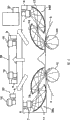
As the Worn type display, known have a kind of method little beam splitting mirror 40 to be disposed at a part in the visual field shown in Figure 16 (a), and the image projection of image output elements 39 such as plasma display, liquid crystal being exported through the deflection of above-mentioned beam splitting mirror 40 by projection optical system 38 is to the retina of eyeball.This method beam splitting mirror, thereby belong to image that image output element 39 exported and appear this mode of a part (first kind) in the visual field in one's mind.But its field-of-view angle only has several times size, thereby can be used in the image information prompting etc. of mobile phone.
And, this method shown in Figure 16 (b) is arranged then as obtaining the method for bigger a little image information again.This is that bigger optical element 41 is disposed at before the eyeball, the method for the image projection of image output element 39 being exported by a plurality of reflectings surface and projection optical system 42 to the eyeball retina.This type can obtain relatively large field-of-view angle (15~30 degree size), but proposition only is to cover this type of the visual field fully.Thereby, proposed releasably to be arranged at this mode of display (second type) or the eyes that single eyes front is used for the Worn type personal computer as usage the substitute this mode (three type) of identical image display device as televisor, projector independently has been set.
Based on 3 types of above-mentioned prior art, can expect to become the Worn type display that substitutes mobile phone, notebook computer, televisor, projector respectively.But in fact, can wear this advantage though have, but the visual field of display size does not have too big difference with existing display, covers the eye fatigue that is caused, the weight that ear or head carried etc. if consider trouble, the visual field of installing when wearing, and has the obvious this shortcoming of defective.
The present invention is just at this situation, and its purpose is, a kind of image display device of wearing or can using near eyes that approaches the big field-of-view angle in the human finding visual field that has is provided.
Disclosure of an invention
First invention in order to achieve the above object is a kind of image display device, for being contained in described eyeball image display device at the moment, has: be equipped with and the light beam exit direction two-dimentional light emitting-type photovalve of the display surface of quadrature mutually; And the light beam of described photovalve institute outgoing projected in user's eyeball, has the flake type optical systems of 60 degree with upward angle of visibility, the part of this image display device can with user's facial contact, at least described in addition photovalve and described flake type optical system can be supported by the supporting mechanism beyond the user, and described supporting mechanism can move with user's face action and supports to comprise described photovalve and described flake type optical system in interior unit.
Description of drawings
Fig. 1 is the synoptic diagram that first example in the embodiment of the present invention is shown.
Fig. 2 is the synoptic diagram that second example in the embodiment of the present invention is shown.
Fig. 3 is the schematic diagram that the 3rd example in the embodiment of the present invention is shown.
Fig. 4 is the synoptic diagram that the 3rd example in the embodiment of the present invention is shown.
Shown in Fig. 5 be eyeball when rotating the image information scope that can see.
Fig. 6 is the schematic diagram that four embodiment of the invention is shown.
Fig. 7 is the synoptic diagram that the 5th example in the embodiment of the present invention is shown.
Fig. 8 is the synoptic diagram that the 6th example in the embodiment of the present invention is shown.
Fig. 9 is the synoptic diagram that the 7th example in the embodiment of the present invention is shown.
Figure 10 is the key diagram of the image input information with the 7th embodiment when being transformed to image output information.Figure 10 (a) illustrates light-sensitive image, and Figure 10 (b) illustrates the output picture of 24L liquid crystal type two dimension output unit 6, and Figure 10 (c) illustrates the output picture of 24R liquid crystal type two dimension output unit 6.
Figure 11 is the synoptic diagram that the 8th example in the embodiment of the present invention is shown.
Figure 12 is the key diagram when for image is synthetic outside input image information being carried out the distortion correction.
Figure 13 is the synoptic diagram that the 9th example in the embodiment of the present invention is shown.
Figure 14 is the key diagram when for image is synthetic a plurality of outside input image informations being carried out the distortion correction.
Shown in Figure 15 is the tenth example that can shirk the embodiment of the present invention of image information inputting apparatus and commutative color from the image information output unit.
Figure 16 is the concept map of two routine prior aries.
Shown in Figure 17 is parallel beam convergent position in fish eye optical systems of inciding crystalline lens A from 3 different directions.
Shown in Figure 18 is to insert the formation of revising optical system, relaxing its imaging surface asymmetry near the common focus position of two elliptical reflectors.
Shown in Figure 19 is the method that reverse fish-eye lens mechanism is set in eyeball, reduces the visual angle.
Shown in Figure 20 be for make the eyeball emergent light relay to prescribed level liquid crystal type two dimension output unit and with the formation of f θ reflective mirror.
Shown in Figure 21 is the state that left and right sides eyes dispose formation shown in Figure 20 respectively.
The method example that is to use optical reflector of curved surface that this imaging surface bending is revised shown in Figure 22.
Shown in Figure 23 is the embodiment of a routine display device.
Shown in Figure 24 is the pattern formation of video camera.Arrow illustrates the visual field direction.
Shown in Figure 25 be when forming image at a distance and the left and right sides image display device when closely forming image in focusing position and the direction of visual lines of eyes.
Shown in Figure 26 is concrete example during by beam splitting mirror optics composograph.The 91st, the left eye visual field corresponding VGA liquid crystal cell output image, the 92nd, the left eye visual field corresponding XVGA liquid crystal cell output image, the 93rd, the composograph that left eye visual field retina can be seen.
Shown in Figure 27 is that image when described zoom system, pancreatic system is adjusted is synthetic.Figure 27 (a) illustrates film and views and admires and use occasion, and Figure 27 (b) illustrates full visual field and observes that use occasion, arrow to illustrate from film ornamental use zoom be full visual field observation purposes.
Shown in Figure 28 is to comprise in the flake type optical system of eyepiece the configuration display device example of focusing control gear automatically.
Shown in Figure 29 is to comprise in the flake type optical system of eyepiece the configuration camera head example of focusing control gear automatically.
Shown in Figure 30 is that the criminal of preventing and the purposes of taking precautions against natural calamities, animal are appreciated used fixed image mechanism examples such as purposes.
Figure 31 is the overall pie graph that the console mode image display device is shown.
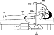
Shown in Figure 32 is the state when using full field-of-view angle display device of lying low.
Figure 33 is the synoptic diagram that the facial matching mechanism of absorption type of full field-of-view angle display device is shown.
Figure 34 is the vertical view during from the full field-of-view angle display device of top observation.
Figure 35 is the mode chart that comprises the flake type optical system of eyepiece in the embodiment of the present invention, and what illustrate is when considering that human eye rotational action makes crystalline lens move 20mm ± 70 ° of light beams.
Figure 36 is the mode chart that comprises the flake type optical system of eyepiece in the embodiment of the present invention, and what illustrate is light beam when the eye pupil size is set at common indoor size and is the 3mm left and right sides.
Figure 37 is the mode chart that comprises the flake type optical system of eyepiece in the embodiment of the present invention, and what illustrate is deliberately to have according to the field-of-view angle of distance optic centre to carry out the imaging surface of the out of focus light beam when crooked.
Figure 38 is the mode chart that comprises the flake type optical system of eyepiece in the embodiment of the present invention, and what illustrate is the light beam that focusing position also less changes this occasion under the rotary state.
Figure 39 is the mode chart that comprises the flake type optical system of eyepiece in the embodiment of the present invention, and what illustrate is light beam when watching the place ahead 50cm object with eyes.
Shown in Figure 40 is the example that keeps full visual field type display device with the mechanical arm technology.
Shown in Figure 41 is to bear a heavy burden with balance to offset the example of full visual field type display device loading.
Shown in Figure 42 is to make full visual field type display device move example freely with universal coupling.
Shown in Figure 43 is to be reduced to the imaging surface bending at image planes place and the example of the optical system that the heart far away tilts with bitoric lens.Figure 43 (a) laterally moves the occasion of (eye rotates) for no eyeball, and Figure 43 (b) is the occasion that eyeball laterally moves (eye rotates) 30 °, and arrow illustrates image output.
Shown in Figure 44 is the light beam state of each field angle in the optical system shown in Figure 43.
Shown in Figure 45 is the corresponding various aberrations of characteristic shown in Figure 44, and Figure 45 (a), Figure 45 (b), Figure 45 (c) all illustrate spherical aberration, astigmatic image error, distortion successively from the left side.
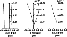
Shown in Figure 46 to be light beam relay to the example of the optical system of diffusing glass from the liquid crystal output face, Figure 46 (b) illustrates aberration, and spherical aberration, astigmatic image error, distortion are shown successively from the left side.
Shown in Figure 47 to be light beam relay to the example of the optical system of diffusing glass from the liquid crystal output face, Figure 47 (b) illustrates aberration, and spherical aberration, astigmatic image error, distortion are shown successively from the left side.
Figure 48 is the mode chart that utilizes the device of the embodiment of the present invention of optical system among Figure 44 (a) and Figure 47.
Shown in Figure 49 is the contrast of the finishing room of existing finished product and embodiment of the present invention.
Shown in Figure 50 is that balance bob is deposited in the state that support sector keeps full field-of-view angle display device.
Shown in Figure 51 is that balance bob is deposited in the state that support sector keeps full field-of-view angle display device.
Figure 52 is the mode chart that a csr optical system in the embodiment of the present invention is shown.
Embodiment
Below with figure explanation embodiment of the present invention example.Fig. 1 is the synoptic diagram that embodiment of the present invention first example is shown.Fig. 1 is the sectional view of the people's that sees from the top head, and left side of head is shown, and the drawing lower right illustrates face contour 3, the left eye eyeball 1L of portion, lens of left eye 2L and horizontal nose 4.The drawing top then is broad visual field part, is formed on the CCD two-dimensional array sensor 9 by image by the wide territory picture of the first flake type optical system 10 with broad visual field.In the case, the first flake type optical system 10 has the field angle of wide-angle, will change into light pencil from the light beam of object in its visual field, and the picture of above-mentioned object is imaged on the CCD two-dimensional array sensor 9.
In addition, so-called " flake type optical system " generally is meant and can provides the optical system that can clearly hold the more broad field angle of the field range of object color or its detail section than the mankind in this instructions and claims, not only comprise the optical system that is commonly called fish-eye lens (lens that have 180 ° of field angle with respect to screen diagonal), also comprise wide-angle lens (having 60 ° of lens) to 90 ° of field angle with respect to screen diagonal, extrawide angle lens (lens that have 90 ° or above field angle with respect to screen diagonal), and field angle is 30 ° or above standard lens.In addition, with regard to embodiment of the present invention, better be the optical system that has field angle more than 90 ° with respect to the diagonal line of field angle size.
In other words, in this instructions and claims so-called " flake type optical system " be meant with general projection optical system mutually specific energy obtain the broad sense optical system of broader visual field information, much less common wide-angle lens, fish-eye lens comprise that also comprising non-spherical lens, cylindrical lens etc. has special optical system of astigmatic image error etc.In addition, also be included in length and breadth for elliptical reflector and have the Special Elliptic reflective mirror of the different astigmatic image error of curvature or elliptical reflector on the single shaft direction etc. only on the direction, the explanation in this instructions and claims is all as prerequisite.
The image of CCD two-dimensional array sensor 9 offers liquid crystal type two dimension output unit 6 by image processing apparatus 8 as output image information.Liquid crystal type two dimension output unit 6 is by back lighting, from corresponding with output image information look like suitable pixel emergent light.This light is dispersed from the imagination focus as the light beam of dispersing in polarizers of big angle scope once more by the second flake type optical system 7.Here, these divergent beams are by three-dimensional elliptical reflector 5 deflections, because be that above-mentioned imagination focus is positioned near first focus of three-dimensional elliptical reflector 5 with optical system configurations, these divergent beams are concentrated near second focus of three-dimensional elliptical reflector 5.
To be wide area image be imaged in the left eye eyeball 1L of portion on the retina as projection image near the lens of left eye 2L that has the left eye eyeball 1L of portion second focus, result.Lens of left eye 2L is positioned near second focus, is to use so that the pupil position basically identical of the pupil location of optical system and eyeball reduces the light waste.
Specifically, formed picture pattern imaging on retina on the face of liquid crystal type two dimension output unit 6, become spread all over the whole zone of retina effective field of view or with the picture of its access areas.Thus, can form picture with covering visual field integral body or its most of this field-of-view angle.
And as shown in Figure 1, the mid point of two focus lines by three-dimensional elliptical reflector 5 and the face vertical with this line intersect with the reflecting surface of three-dimensional elliptical reflector 5.Thus, the reflecting surface of three-dimensional elliptical reflector 5 is obtained broad, and the whole or major part that can reflect the emergent light that CCD two-dimensional array sensor 9 dispersed is concentrated near second focus.
In addition, " the imagination focus be arranged in three-dimensional elliptical reflector 5 first focus near ", " near the lens of left eye 2L that has the left eye eyeball 1L of portion second focus " this record " near " implication is meant, be have 60 the degree above angle of visibility image display device in this case, as long as the loss that the light waste is caused is unchallenged in fact degree, also can strictness be positioned at the focal position, though second focus and the lenticular position relation that means is allowed this skew with the installing additional and skew is arranged of image display device.In this instructions and claims,, all near " focus " this term is used for explaining above-mentioned implication as long as do not mention specially.
Among Fig. 1,2 focuses that for convenience of explanation should three-dimensional elliptical reflector 5 are shown in broken lines in fact also non-existent oval part.In the middle of the following accompanying drawing, when being shown, also uses by catoptron this method for expressing.
In the embodiment shown in Figure 1, observe light beam and know that also the light beam in the left eye eyeball 1L of portion is different with the second flake type optical system, 7 its angles of pairing light beam.Specifically, bigger distortion takes place.Image processing apparatus 8 by this is taken in, adds that numeral revises to the input information of CCD two-dimensional array sensor 9 on the image of liquid crystal type two dimension output unit 6 outputs, can be to projection preferable image on the retina in the left eye eyeball 1L of portion.
But conventional CCD two-dimensional array sensor and liquid crystal type two dimension output unit are the aggregate of limited photo-sensitive cell and liquid crystal cell, if adding numeral revises, the distorted portion of being compressed just can't make information rationally decompress, thereby exploring degree variation, can't obtain preferable image.
Fig. 2 summary illustrates the second embodiment of the invention of avoiding this situation.In the following accompanying drawing, the ingredient identical with ingredient shown in the previous accompanying drawing often adds same numeral, omits its explanation.But for convenience of description, also add this situation of different labels for the same composition part.And, for the left eye purposes is shown, beyond numeral, add L behind the character, then add R and represent for the right eye purposes is shown, for identical and for left and right sides eyes shared then omit L with same numbers or character and R represents.
In the present embodiment, be not that the second flake type optical system 7 is directly inserted first focus of three-dimensional elliptical reflector 5, produce the virtual light source of dispersing at this focus section.By the wide area picture of the first flake type optical system, 10 compressions, projection image is imaged on the CCD two-dimensional array sensor 9 by image from the broad visual field.In the case, the first flake type optical system 10 has wide-angle view, makes the light beam of object in its visual field become light pencil, thereby the picture of above-mentioned object is imaged on the CCD two-dimensional array sensor 9.
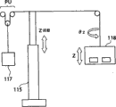
The image of CCD two-dimensional array sensor 9 can offer liquid crystal type two dimension output unit 6 as output image information by image processing apparatus 8.Liquid crystal type two dimension output unit 6 makes light outgoing from corresponding with output image information as pairing pixel by back lighting.This light becomes parallel beam by the distortion correction optical system 13 that comprises f θ lens, is become the light beam by its focus again by 12 reflections of f θ reflective mirror.The focal position of this f θ reflective mirror is configured to consistent with second focus of three-dimensional elliptical reflector 5.
Thereby, the emergent light of liquid crystal type two dimension output unit 6, becoming from the focus of f θ reflective mirror 12 is the diverging light that second focus of three-dimensional elliptical reflector 5 is dispersed, has broad dispersion angle and by 5 reflections of three-dimensional elliptical reflector, be concentrated near the lens of left eye 2L of the left eye eyeball 1L of portion that disposes this first focus near, image in the left eye eyeball 1L of portion with broad angle.So, constitute by allowing eyeball be subjected to light beam from liquid crystal type two dimension output unit 6, accept the output information of CCD two-dimensional array sensor 9.Distortion correction optical system 13 is to have the optical system that this function is revised in the aforesaid distortion that three-dimensional elliptical reflector 5 is taken place.
In this case, though can revise the distortion that three-dimensional elliptical reflector 5 produces by distortion correction optical system 13, but be difficult to only depend on distortion correction optical system 130 to revise the distortion that the first flake type optical system 10 is taken place, still to obtain preferable image by carrying out the numerical distortions correction by image processing apparatus 8.
So-called in this instructions and claims " f θ reflective mirror " is to instigate the light beam of pointolite institute outgoing to become this broader sense of reflective mirror of parallel beam, as the catoptron general name with this effect.
Fig. 3 illustrates the principle of third embodiment of the invention.Among Fig. 3, make f θ reflective mirror come to substitute the first three-dimensional elliptical reflector 5 shown in Figure 2 relatively, form 2 focuses with a f θ reflective mirror 15 and the 2nd f θ reflective mirror 14.Here know, in case first focus (focus of a f θ reflective mirror 15) is placed near the crystalline lens 2 ' of imagination eyeball 1 ', and second focus (focus of the 2nd f θ reflective mirror 14) is placed near the lens of left eye 2L of the left eye eyeball 1L of portion the same light beam that the light beam inside of virtual eyeball 1 ' and the left eye eyeball 1L of portion is just overturn for rotational symmetry with respect to the Y-axis axle of mid point by these 2 focuses (perpendicular with 2 f θ reflective mirror focus lines and).In addition, be to make the optical axis of the optical axis of a f θ reflective mirror 15 and the 2nd f θ reflective mirror 14 corresponding among Fig. 3, get final product but above-mentioned optical axis is parallel, not necessarily need consistent.
Fig. 4 summary illustrates the third embodiment of the invention of using this principle.The top is a broad visual field part among Fig. 4, and the wide territory by 10 pairs of broad visual fields of the first flake type optical system looks like to compress, and projection image is imaged on the CCD two-dimensional array sensor 9 by image.In this case, the first flake type optical system 10 has wide-angle view, and makes the light beam of object in its visual field become light pencil, thereby the picture of above-mentioned object is imaged on the CCD two-dimensional array sensor 9.
The image of CCD two-dimensional array sensor 9 offers liquid crystal type two dimension output unit 6 by image processing apparatus 8 as output image information.Liquid crystal type two dimension output unit 6 is by back lighting, by making the light outgoing with output image information is corresponding as pairing pixel.This light is dispersed as the light beam of dispersing in than polarizers of big angle scope once more by the second flake type optical system 7.And the imagination focus that the second flake type optical system 7 is configured to this second flake type optical system 7 is that the light eye point is consistent with the focal position of a f θ reflective mirror 15.
Thereby, the emergent light of the second flake type optical system 7, the wide region reflection by a f θ reflective mirror 15 becomes parallel beam, incides the 2nd f θ reflective mirror 14.Because the optical axis of a f θ reflective mirror 15 and the optical axis of the 2nd f θ reflective mirror 14 are consistent, thereby this incident light is concentrated on the focus of the 2nd f θ reflective mirror 14.The lens of left eye 2L of the left eye eyeball 1L of portion is positioned near this focal position, so pass through crystalline lens through the light of optically focused, forms the inverted image with broad degree identical with the imagination focus on the retina in the left eye eyeball 1L of portion.Thereby the wide angle of visibility for identical with the effective field of view angle or approaching therewith can obtain preferable image.In this method, the distortion that foozle, step-up error etc. are caused only takes place, numeral revises almost not having as the state variation of causing.In addition, the optical axis of the optical axis of a f θ reflective mirror 15 and the 2nd f θ reflective mirror 14 is consistent to be desirable, but parallelly can obtain effect same.
But in the 3rd embodiment, as shown in Figure 4, not too the 2nd f θ reflective mirror 14 can be extended to the left side of Fig. 4, but thereby restricted with the nose 4 rightabout sensitization visuals field, add the eyeball action time just make wide territory picture that people institute can see wherein a part waste.
Fig. 5 illustrates this situation.Fig. 5 (a) is illustrated to be the situation that does not add eyeball 1 action, as long as consider the visual field of scope shown in 22.With headed by the light beam 12 of positive incident, all fully cover the scope of crystalline lens 2 from the light beam 11,13 of oblique incidence.But add that field range expands to scope shown in 22 among Fig. 5 (b) under the situation of eyeball 1 action.Fig. 5 (b) is illustrated to be the situation that eyeball moves in the direction of the clock, and in this case, does not have the light beam incident of direction shown in the α among the figure in the visual field, and this part becomes the blind area, and the visual field is part shortcoming wherein.
Fig. 6 illustrates the principle of the four embodiment of the invention that can address this is that.For ideal situation is shown,, in statu quo wide area image is carried out sensitization among Fig. 6 by the inner CCD element of sphere by the lens 21 and the spherical CCD photosensitive sensor 20 of the human eyeball structure of imageneering.By the output of the output information of spherical CCD photosensitive sensor 20 as image processing apparatus 8, by the spherical liquid-crystal apparatus 19 of the human eyeball structure of same imageneering, in statu quo make liquid crystal image as the outgoing of diffusion light beam by lens 18 with lens 21 identical performances.
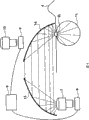
Enter the light beam of lens 21, be reproduced as light beam with the identical light path of light beam of 18 outgoing of lens.If can be on the lens of left eye 2L of the left eye eyeball 1L of portion this diffusion light beam of identical reproduction, the result is, enters the visual field, the wide territory information of lens 21 and enters image information equivalence fully in the lens of left eye 2L, almost do not have distortion to take place.In order to realize this effect, what use in the 4th embodiment is 2 elliptical reflectors 17,16.
Specifically, first focus of first elliptical reflector 17 is disposed near the lens 18, make first focus of second focus of first elliptical reflector 17 and second elliptical reflector 16 consistent, and second focus of second elliptical reflector 16 is disposed near the lens of left eye 2L.And constitute, on the focus dead in line of above-mentioned elliptical reflector, and the center of first focus by first elliptical reflector 17 and the second focus line and with this line plane orthogonal with the reflecting surface of the beam deflection of first elliptical reflector 17 is intersected.
Therefore, the light beam equivalence in light beam in the left eye eyeball 1L of portion and the spherical liquid-crystal apparatus 19 can be reproduced the diffusion light beam of said lens 18 outgoing identically on the lens of left eye 2L of left eye ball 1L.Do not need to make above-mentioned conditionally complete to meet, but the degree of deterioration of distortion and other aberrations is corresponding with the degree that departs from above-mentioned condition, thereby when departing from top condition, wishes to carry out the distortion correction of numeral because of design constraints etc.Here, adopt elliptical reflector, and the elliptical reflector that is adopted be first focus by first elliptical reflector 17 and the second focus line the center and with this line plane orthogonal and the reflecting surface that makes the beam deflection of the first elliptical reflector 17 this elliptical reflector that intersects with wide reflecting surface.
Thus, can comfort oneself the in the future information in the visual field, territory is sent into lens of left eye 2L.Therefore, finally the information that enters the visual field, wide territory of lens 21 in statu quo can be reproduced on the left eye eyeball 1L of portion retina by lens of left eye 2L, can be spreaded all over broad angle of visibility and well be looked like.And, Fig. 4 and Fig. 6 contrast is known that Fig. 6 situation also can be guaranteed the enough wide visual field in the left side of the left eye eyeball 1L of portion, the left eye eyeball 1L of portion rotates and also can obtain required field-of-view angle when mobile.
But be difficult to design spherical type CCD photosensitive sensor 20, spherical liquid-crystal apparatus 19, can expect that manufacturing cost also increases.On the other hand, Fig. 7 illustrates its summary of fifth embodiment of the invention as the variation of the present invention first~the 3rd embodiment.This mode is for adopting the essentially identical flake type of characteristic optical system 10,7, CCD two-dimensional array sensor 9 that characteristics such as effective field of view are same approaching and liquid crystal type two dimension output unit 6 this modes.Even if effective field of view there are differences, also can adjust and remedy difference, but wish to meet as far as possible distorted characteristic the projection multiplying power of flake type optical system 10 and 7.
Specifically, the wherein quick-witted sensitivity of human intraocular retina, exploring degree height are just and as long as periphery can be observed its shape, sufficient effect is played in action aspect quantity of information.Utilize this situation, expand central information but this specific character of compression peripheral information by utilizing with the first flake type optical system 10, the visual field, wide territory information projection is stored on the CCD two-dimensional array sensor 9 to the plane, by plane liquid crystal type two dimension output unit 6 outgoing identical information, reduce by the second flake type optical system 7 again with this characteristic, through first elliptical reflector 17 and second elliptical reflector 16, image information is sent into crystalline lens 2L.Thus, can make good imaging on the losing of no middle body data, the retina of the visual field, wide territory information in left eye ball 1L that distortion is little.
Here, as fish-eye lens, the most effectively adopt little at the highest field-of-view angle of human eye usage frequency 60 degree with interior distortion distortion, to its periphery about the non-linear fish-eye lens that compresses of the image of 30 ° of sizes.Because with regard to above-below direction, the effective field of view angle minimum of eye, thereby make rectangular shorter direction be about, CCD two-dimensional array sensor 9 and liquid crystal type two dimension output unit 6 are set about than length direction being, just can obtain high-resolution.
Be out of shape the image display device of eyes correspondence shown in the application examples afterwards in shown in Figure 8 the 5th embodiment is passed through below, but much less, this distortion can be carried out also to above-mentioned first embodiment to the, four embodiments.
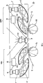
Fig. 8 summary illustrates sixth embodiment of the invention image display device, the eyes mirror that left eye ball 1L not only but also right eye ball 1R also are provided with the 5th embodiment.With 23L the image display device that left eye ball 1L uses is shown, the image display device that right eye ball 1R uses is shown with 23R.The mankind have difference at two eyeballs aspect at interval certainly, if can't revise this, the visual field that can see is variation and have discomfort just.Internal mechanism is independent fully in this embodiment, thereby can select composing images display device cover, make the interval of image display device 23L and 23R to finely tune as shown by arrows to meet with the center be the boundary two eyeballs at interval.
And this formation so is provided with the visual field, wide territory photographic department, and making the Center Gap of winning between the flake type optical system 10 at interval with eyes is same intervals.Specifically, independently by image display device 23L left eyeball 1L image information is provided, by image display device 23R to the right eyeball 1R image information is provided, human resulting information just is identified as steric information.Here, if both first flake type optical systems 10 of image display device 23L, 23R and CCD two-dimensional array sensor 9 are adjusted to direction separately, the stereoscopic sensation of image just increases, and is applied to its effect of occasion such as recreation and is improved.It is the structure that kind of above-mentioned interval can be adjusted according to purposes like this.In addition, there are interference in the first flake type optical system 10, CCD two-dimensional array sensor 9 and second elliptical reflector 16 in this case, and it is provided with the position and can also can as required it is taken off good in the bottom on the top of second elliptical reflector 16.Image display device cover 25 is designed to realize this mode.
The 6th embodiment shown in Figure 8 be for can providing the device of stereo-picture, but as image information when watching this purposes of static information such as newspapers and periodicals, do not need to be stereo-picture.This occasion, as seventh embodiment of the invention, both are good as shown in Figure 9 the first flake type optical system 10, CCD two-dimensional array sensor 9 to be used for image display device 24L, 24R.Therefore, cost reduces equipment miniaturization the time.But at this moment, as shown in figure 10,, need provide different information to image display device 24L, 24R as adding in the image information of 9 sensitization of CCD two-dimensional array sensor with the eyes interval with to this image information of skew that the distance of object is consistent.
Specifically, though the image that is absorbed by CCD two-dimensional array sensor 9 shown in Figure 10 (a), left eye is with the skew of also can turning left of the image of image display device 24L, makes the point that meets with left eye eyeball 1L position be in the center, just the visual field, right side lacks.Otherwise right eye is with the skew of then turning right of the image of image display device 24R, makes the point that meets with right eye eyeball 1R position be in the center, and left visual field just lacks.Even if the picture of observing with CCD two-dimensional array sensor 9 with this way is in this occasion at the moment, also cooperate the focusing of carrying out being consistent to control as crossing with distance to above-mentioned object, just can reproduce picture brightly, and can form illusion for as distant objects, play this effect of eye fatigue that prevents.
Figure 11 summary illustrates eighth embodiment of the invention.This embodiment is the application examples of above-mentioned the 7th embodiment, and image display device cover 26 can be fixed the digital video unit 28 that only is made of image photographic department branch here.Constituting of this device, only chase the shooting object while using left-handed operation varifocal switch 29 by the action of head and body, to synthesize from the external information of video unit 28 and by the first flake type optical system 10 and the visual field, CCD two-dimensional array sensor 9 resulting wide territory information by image information control device 27, this information will be offered image display device 24L, 24R.
This information as both sides' common images information stores in image information control device 27, thereby later on can by replace the image size, synthetic method be used as video data and watch again.And this video unit 28 also can take off from image display device cover 26 as required.
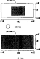
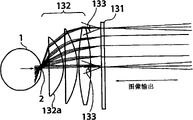
Shown in Figure 12 is image combining method in the image information control device 27.As indicated above, by 10 projections of the first flake type optical system, the projection image of the pattern 200 shown in (a) of sensitization becomes (c) this pattern 200 that peripheral part is compressed on CCD two-dimensional array sensor 9.On the other hand, external information 201 shown in (b) that video unit 28 is imported does not have this distortion, thereby image display device 24 is when exporting external information 201 big, need be on the basis of the information that is modified to the peripheral distortion that has added the first flake type optical system 10 in advance (at this moment the original image of external information 201 is corrected for coil former shape image in (c)) to carry out image synthetic, and by 6 outputs of liquid crystal type two dimension output unit.
Adopt this method just can obtain final (d) this undistorted good image by the distortion of the second flake type optical system 7.In addition, for distortion is shown easy-to-understandly, the pattern that stretches with four bights shows here, but actual fish-eye lens is opposite, and four jiaos object is a this shape of bucket.These can have the consideration different shape according to the characteristic of fish-eye lens.
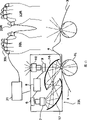
Figure 13 summary illustrates ninth embodiment of the invention.This embodiment is used for single eyes with the image display device 23L of the 5th embodiment, the control device 31 that will have personal computer function is connected with image display device 23L, and the finger tip of 32L is provided with portable keyboard 33L leftward, and the finger tip of right hand 32R is provided with portable keyboard 33R, and Figure 14 illustrates the image combining method of this moment.
Each finger tip of portable keyboard 33L, the 33R of Figure 13 is provided with sensor and the finger pressure sensor that the direction of leaving thumb and position are detected, and forms as this each finger tip action and is exported this structure with the relative position image information of thumb.
Among Figure 14, need be with by 10 projections of the first flake type optical system, by the pattern 200 shown in (b) of 9 sensitization of CCD two-dimensional array sensor, the synthetic display pattern that needs high-resolution 203 (diagram in (c)) that shows that computing machine is exported, and the pattern 205 (diagram in (d)) of the synthetic equally display keyboard input information of tool bar 204 (diagram in (a)) that shows with the computer screen periphery.
As indicated above, the image of liquid crystal type two dimension output unit 6 outputs comprises the distortion information that the above-mentioned first flake type optical system is taken place, as (e) the periphery position compressed image information that is shown in.Therefore, for the image information from the outside is tool bar 204, keyboard input display part 205, if shown in (e), be transformed to the words that this image information of inverse modified is synthesized are carried out in the distortion of the second flake type optical system 7, just because the distortion of the second flake type optical system 7, on the eyeball retina, shown in (f) image, be reduced to the projection image that does not have distortion, thereby preferable image information can be provided.In addition, the display image that needs high-resolution 203 for computing machine does not carry out the distortion correction, and this is because this part is positioned at visual field central authorities among Figure 14, does not need to consider the influence of distortion.
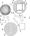
Figure 15 is the key diagram of explanation the tenth embodiment, this embodiment can shirk the image information inputting apparatus of being made up of the first flake type optical system 10 and CCD two-dimensional array sensor 9 in the middle of image information output units such as liquid crystal type two dimension output unit 6, the second flake type optical system 7, thereby can carry out various transposings.Words for the wide territory of routine image pattern picture, can assemble image information inputting apparatus 35, and be the words of three-dimensional wide territory image pattern picture, can assemble the corresponding independently stereo-picture input media 36 of the first flake type optical system 10 and CCD two-dimensional array sensor 9 that has respectively with left and right sides eyes, and be enlarged image, then can assemble the optical system with long-focus and the high magnification image-input device 37 of imaging apparatus.And, in order to shorten the depth of image display device, in being the second flake type optical system 7 of image output device 34L, 34R, the image information output unit uses tortuous reflective mirror, among this figure at horizontally set liquid crystal type two dimension output unit 6.The image exploring degree of this device depends on the size of liquid crystal cell to a great extent, thereby this part hope is designed to form intensified image as much as possible by the second flake type optical system 7, and is less relatively for the liquid crystal cell of image.
As intensified image,, can design flake type optical system itself less, obtain the screen of lcd segment bigger with the optical system of the non-heart far away.But this occasion needs liquid crystal portion illumination light also to have and the corresponding directivity of flake type optical system.In addition, light beam is cut apart, adopted used G, B, these 3 liquid crystal portions of R in the projector,, also can appreciate and the equal high exploring image of projector with the broad visual field though size is big.
In addition, if, the multiplying power chromatic aberation that relay optical system took place is attempted adjusting G, B, R multiplying power separately, also have and to reduce this advantage of achromatic lens sheet number with G, B, these 3 liquid crystal portions of R.But as indicated above, image output device itself is bigger, thereby for be attached to the device that head uses as head mounted display, glasses type displayer, preponderance just is not suitable for.For this is improved, also have image output device is fixed in user's this method of part in addition, owing to be fixing position, existence can't adapt to user's free position, can bring this problem of sense of restraint.For head it off, although the back will illustrate, it is desirable to form above-mentioned image display device wherein at least a portion support by part beyond the user, also contact, and with the removable this mechanism of user's face action with user's face.
In addition, can also conversely liquid crystal type two dimension output unit 6 be replaced into this material of photographic film that the first flake type optical system is absorbed.Also can move this film, stamp illumination and appreciate and looking like like the magic lantern photograph by rotation or lantern slide mode.This design can be used as toy, also can be used as the photograph preservation method, no matter which kind of situation all can be brought unprecedented telepresenc.
More than mainly in the middle of the explanation being noted that the embodiment that adopts elliptical reflector, but under the above-mentioned formation situation, is imaging surface for the focal position of Z direction, even if also be not complete symmetry with 2 elliptical reflectors.Figure 17 illustrates parallel beam convergent position in the fish eye optical systems that adopts 2 elliptical reflectors of inciding crystalline lens A from 3 different directions with zero.So just, know because of beam direction the asymmetric generation of bigger imaging surface is arranged, the image that liquid crystal type two dimension output unit 6 is exported has suitable tightening up to deepen the depth of focus near pupil, or to the asymmetric correction optical system of revising of this imaging surface.
But can't obtain to cover the visual field of eye rotation action like this, so need to relax the asymmetry of this imaging surface.In order to address this problem, near both common focus positions of elliptical reflector 16,17, to insert and revise optical system 43, and relax the asymmetry of this imaging surface among Figure 18.As revise optical system 43 imported make revise optical system 43 fronts focus once more imaging have a non-spherical lens that then has the lensing a little less than the degree on its orthogonal directions of the strong lensing of degree.Thus, can change each focal position arbitrarily, can under the state that relaxes the imaging surface asymmetry, obtain broad visual angle.
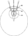
Provide the application examples that adopts f θ reflective mirror below.Adopt its shortcoming of technology of above-mentioned f θ reflective mirror to be, can't obtain than the more broad visual field of method of adopting elliptical reflector.For this is improved, reduce the broad visual angle of human eye earlier, adopt this method of f θ reflective mirror comparatively effective then.With Figure 19, Figure 20, Figure 21 its method is described.
Figure 19 is provided with reverse fish-eye lens mechanism (effect of eyepiece optical system is played by this mechanism) to eyeball 44, and the broad visual field that formation and eyeball 44 retinas are reflected is as this method of the corresponding virtual image.The retina that makes eyeball 44 is the light beam of imaging point, is that the eyepiece 45 on plane has made it big deflection by the face of eyeball 44 1 sides.Eyepiece 45 is in the opposite sides of eyeball 44 1 sides, the lens of this curvature of approximate centre that to adopt its curvature of face center be eyeball 44, and form incident beam and the basic quadrature of this curved surface tangent line to this curved surface one side.And next lens 46 equally also is that the face of eyeball 44 1 sides is the plane, and the formed curved surface of opposite sides by adopting regulation curvature and lens material, makes incident beam and the basic quadrature of this curved surface tangent line to this curved surface one side.By satisfying this condition, can obtain the good image that does not almost have coma to take place in planar side and curved sides.(not mentioned here chromatic aberation, but need take in not narration specially here to liquid crystal portion to the integral body of eyepiece lens 45).
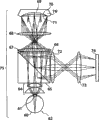
But this constantly, still is in dispersal direction from the light beam of eyeball 44.Thereby, in order to relay to the liquid crystal type two dimension output unit of given size, wish to adopt above-mentioned f θ reflective mirror (in addition, more than in the explanation in order to simplify, carried out light beam from this explanation of eyeball, but the light beam that is actually the outgoing of liquid crystal type two dimension output unit arrives the retina in the eyeball 44.)。
With Figure 20 its optical system mechanism 55 is described.Outgoing beam from liquid crystal type two dimension output unit 54 can form the diffusion light beam by the lens 53,52,51 that constitute the second flake type optical system, form parallel beam by f θ reflective mirror 50, the line symmetry f θ reflective mirror 49 that is in f θ reflective mirror 50 and f θ reflective mirror 40 both centers by the pupil location that is configured to its optical system relatively forms the optically focused light beam, the reverse flake type optical system of being formed by the illustrated this eyepiece 47 of Figure 19, lens 48, incide in the eyeball 44 with broad visual angle, on retina, form the picture of above-mentioned two-dimentional liquid crystal efferent 54.
By this way, strengthen the beam spread angle with lens 53,52,51, with f θ reflective mirror, the reverse flake type optical system of being made up of eyepiece 47, lens 48 makes the reduction of beam spread angle once more, enter in the eyeball 44, thereby the f θ reflective mirror of comparable previous Fig. 3, Fig. 4 explanation is more effectively obtained broad visual angle.Figure 21 is the image display device that this 55L of mechanism, 55R are set respectively at left and right sides eyes respectively, can not form the asymmetric imaging surface when using elliptical reflector.
During with this way, though be not the non-image planes that are symmetrically, correction was not done in the imaging surface bending of the convex that is easy to produce during with fish-eye lens, can in statu quo stay.This bending is big more near the periphery, therefore still can need pupil is received thin.
Therefore, with Figure 22 the method example of using optical reflector of curved surface that this imaging surface bending is revised is described.Figure 22 is in order to simplify, and what illustrate is to make the divergent beams of the center O institute outgoing of sphere 56 form the parallel this occasion example of chief ray with the way among Figure 19, and the situation that distortion has this shape of y=sin θ (θ is the angle at distance images center) simply is shown.Specifically, the imaging surface when order does not have imaging surface crooked is 59, and actual imaging is looked like shown in 57, and imaging surface 59 and actual imaging face 57 distance between the two when order does not have imaging surface crooked are y, then are y=sin θ as shown in figure 22.
In addition, this situation means, the emergent light of desirable should the be imaging surface 59 on plane is concentrated on an O, but in fact because the imaging surface bending, thereby is that the emergent light of imaging surface 57 is concentrated on an O.
Here, if when reflecting this parallel beam with plane mirror, the imaging surface bending condition is constant fully.But if optical reflector of curved surface 58 and the reflection with regulation curved surface is set near this imaging surface 57, the focal position just changes with this curved surface.
For example in the center of optical reflector of curved surface 58, chief ray e impinges perpendicularly on optical reflector of curved surface 58, in the planar some B imaging of optical reflector of curved surface 58, thereby identical with by flat mirror reflects of each light d, f, e, catoptrical imaginary light source position is constant at the B point.But light a, b, c in the some A of periphery place's imaging reflex to a ', b ', c ' direction by optical reflector of curved surface 58, and this catoptrical imaginary light source is formed at A ' position.Equally, reflex to g ', h ', i ' direction at light g, h, the i of the some C of periphery place's imaging by optical reflector of curved surface 58, this catoptrical imaginary light source is formed at C ' position.Like this, if when forming the reflecting surface of optical reflector of curved surface 58, making A ', B ', C ' be formed on same plane is on the imaging surface 59, just can eliminate sphere 56 formed imaging surface bendings by the reflection of using optical reflector of curved surface 58.
Otherwise, being reflected in the light beam of imaging on the planar imaging face 59 by optical reflector of curved surface, the actual imaging face just is 57, for having the crooked this situation of imaging surface.And this light is offset this imaging surface bending by process curved surface 56, and images in the center of curved surface 56.
This optical reflector of curved surface can be adjusted virtual focus point arbitrarily according to many conditions, but as its cost the heart far away taking place tilts, that is to say, become not parallel from the chief ray of object plane outgoing with optical axis, thereby if carry out big correction, the heart far away tilts and just becomes big, exists light beam can run out of this possibility of effective lens diameter scope.Therefore, the aspheric surface of preferably use selecting: and part that the peripheral focus degree of depth relax little at NA, make the basic quadrature of curved surface and beam incident angle, so that the reflecting surface of optical reflector of curved surface is in its depth of focus, and avoid telecentric beam path that big deflection is arranged, near and the center that the depth of focus is shallow big at NA, virtual focus point is on the imaging surface 59 on plane.
Thereby, as the curvature of the aspheric reflecting surface of optical reflector of curved surface 58, by it is designed in the position between the inclination of two tangent planes of imaging surface flexure plane and such two curved surfaces of virtual focus point face, intermediate, inclined, can obtain above-mentioned desirable image planes.
Illustrate that with Figure 23 an example adopts the embodiment of the display device 75 of this technology below.The top illustrates the frontal in the visual field among the figure.Outgoing beam scioptics 73,72 backs of liquid crystal display 74 are reflected by polarizing beam splitter 65, form circularly polarized light through λ/4 wave plates 66, form the imaging surface 71 that process is revised by lens 67,68 near the correction curved surface 70 of optical reflector of curved surface 76 '.The imaging surface 71 that this process is revised is because the liquid crystal panel is the plane, thereby projection image also is essentially plane (imaging surface 59 that is equivalent to Figure 22 midplane).And, by by 70 reflections of above-mentioned correction curved surface, as described in explanation among Figure 22, image in the bending on the image planes 69 of regulation.λ/4 wave plates 66 and polarizing beam splitter 65 are the devices in order to the preservation light quantity, as long as light quantity is enough, also the half-transmitting reflector of available routine substitutes, and omit λ/4 wave plates.And, under the situation with G, B, these 3 liquid crystal portions of R, owing to have specific polarization orientation in advance, need be noted forming random polarization etc. during with λ/4 wave plates.
By revising the light beam that curved surface 70 reflects, is formed at the virtual image institute outgoing that bends to image planes 69, scioptics 68,67 form linearly polarized light by λ/4 wave plates 66, and the above-mentioned polarizing beam splitter of transmission 65 backs project on the retina 60 of eyeball 62 picture on the liquid crystal display 74 by flake type optical system 64 through crystalline lens 61 brightly.Promptly, crooked imaging surface 69, be that the emergent light of this imaging surface is offset the face that images in after the imaging surface bending of the second flake type optical system 64 on the retina 60, make the picture of the liquid crystal display 74 of the imaging surface 71 that images in the process correction, form the imaging surface 69 of the virtual image of this bending, with the shape of this conditional decision correction curved surface 70.
In this embodiment, owing to can revise the imaging surface bending that flake type optical system is produced, thereby also can utilize for the video camera with distorted characteristic identical with the present invention.Figure 24 is the mode chart of video camera 90, and the drawing below illustrates the visual field direction.The light beam that comes from the outside incides the lens combination 89,88 that constitutes the flake type optical system with the big or small field angle of 140 degree by diaphragm SB, arrives correction curved surface 84 through λ/4 wave plates 81, lens 87,86 behind the transmission-polarizing beam splitter 82.
Constitute the lens combination 89,88 of flake type optical system, have stronger imaging surface bending, thereby imaging surface forms crooked imaging surface shown in 85.But by the crooked reflection of revising the correction curved surface 84 of reflective mirror 90 ' of imaging surface, can imaging surface bending as indicated above be corrected, the catoptrical imaging surface of institute forms the plane imaging surface 83 through correction.And the light of 83 outgoing of imaging surface that process is revised is reflected by polarizing beam splitter 82 through lens 86,87, λ/4 wave plates 81, imports aperture iriss 79 by lens 80.Be tightened to the light beam of prescribed level by aperture iris 79, just be subjected to the effect of lens 78,77 and the picture in the external world is projected on the CCD two-dimensional array sensor 76.
Here, near the imaging surface bending the CCD two-dimensional array sensor 76, the distance that in fact is present in said lens 89 to CCD two-dimensional array sensor 76 is the position of the predetermined radius R of radius R.So, concerning the existing picture of radial location in addition, disperse.Here, above-mentioned aperture iris 79 is dwindled, NA just reduces, and the depth of focus deepens, thereby can focus on the object that is in regulation wide region radius.
When reproducing the output information of CCD photo-sensitive cell 76 with this display device 75 shown in Figure 23, need distinct as the time, enlarge above-mentioned aperture iris 79, Focusing mechanism is arranged at the words of video camera 90, with the picture beyond the focal position is that vague image is opposite, can reproduce distinct picture in the focal position.On the other hand, understand when looking like to compare more comprehensive information, above-mentioned aperture iris 79 is dwindled, can enjoy picture when reproducing with dark depth of focus by above-mentioned display device 75 with distinctness.
Adopt Figure 23, display device 75, video camera 90 shown in Figure 24 as mentioned above, can realize the unprecedented mechanism of observing broad visual field picture.But only this has not talkatively given full play to effect of the present invention, and further effort can be found high value.Therefore, explanation is feasible slightly more effectively utilizes finished product picture of the present invention clear and definite, and realizes the mechanism that this target is used.
At first, clear and definite available display is exported the target that the device in the broad visual field will be realized, can consider following aspect:
1. avoid eyes to feel fatigue;
2. obtain to surpass cinema's telepresenc of projector;
3. obtain to be higher than the picture quality of projector;
4. obtain not having the 3D rendering of sense of discomfort; And
5. obtain to surmount the high new function of added value of human eyes.
For 1.,, come clear and definite required mechanism by considering analysis and improvement to eye fatigue.At first, be positioned " illness that eye fatigue is the modern ", consider to get rid of the mechanism of this reason.
(1) to the long-time use of televisor, computing machine
(a) display is in closer distance and stares.→ other article, the far away sight.
(b) degree of fatigue is pressed televisor, projector, cinema successively from large to small.→ the situation of seeing far away is not tired.
(2) to the use of the Worn type display of market sale
(a) field angle narrow (30 °), focal length be fixing (before the 2m) also.Can't obtain information in addition.→ in video game, make eyes traversing (eye rotates) (wide-angle), watch screen content (wide-angle, zoom) in addition with the broad visual field.
Just add some burdens when (b) eyes focus on.Picture quality is than existing-quality television difference.
(3) the fireballing object of pursuit movement
Watch the fierce nearly thing of motion in the compartment in electric car and recreation ground.→ swing head is fixed sight line, or sees fixed object, or sees at a distance.
If consider the words of The above results, for avoiding the high condition of the necessary possibility of eye fatigue, be meant effectively guarantee to have a wide sphere of vision, picture quality improves, can make eyes laterally move (eye rotates), can see the infinity picture, have the different focus point of multiple spot, is these means of non-motor image in the visual field.
2. the cinema's telepresenc that obtains to surpass projector is discussed below.The mankind feel far and near by making eyes form " neighbour order (to eye) ".Arbitrarily determine the focal position with " neighbour order (to eye) " degree.Even very outstanding projector also have projector distance hereinafter described, and the chamber interior space experience of can't being in resembles the sort of remote image of cinema.
Figure 25 is the key diagram to this explanation that is easily understood, and is under the situation of infinity picture at the liquid crystal cell output image that expression projects to human visual field for example, shown in (b), is projected as seeing picture respectively in aL position, aR position on parallel beam.But when this object is present in closely, make eyes form " neighbour order (to eye) ", the focus of eyes also can be set at arbitrarily as close-ups, thereby the liquid crystal cell output image is projected as seeing picture respectively near inboard bL position, bR position, crystalline lens 2L, 2R and also need to cooperate with it to the focusing of the projection optical system of the element output image of liquid crystal type two-dimensional display.
At this moment, also can consider to attempt the liquid crystal cell output image is moved with electronics and software mode, but also five equilibrium photographically.Five equilibrium photographically owing to be unlikely to lose perimeter data, thereby compared with the software mode parallax with electronics and to be had this advantage of the field image that can keep more broad.Specifically, provide laterally mobile by the assembling Focusing mechanism and to binocular projection's picture, form as Figure 25 (a) mid point c, d, e, any making in close-shot that f is shown in picture~infinity image position and be visualized as this formation of image planes, just can obtain as appearing this telepresenc that surpasses cinema of screen in the air in one's mind.
Next, the picture quality that 3. obtains to be higher than projector is discussed.Existing projector has multiple, and from the exploring degree that is called QVGA 320 * 240 projector in length and breadth, to the exploring degree that is called SXGA 1280 * 1024 projector in length and breadth, the latter forms color images respectively and synthesizes, makes its exploring degree with 3 GRB liquid crystal cells is 3 times.
The projector that the exploring degree is low is used for embodiment of the present invention, and for the picture of cinema's rank size, its liquid crystal cell can be seen with eyes, can lose telepresenc.Thereby, when acquisition is higher than the picture quality of projector, importing is called SXGA be that 3 GRB liquid crystal cells of 1280 * 1024 form color images respectively and synthesize, make its exploring degree in length and breadth with the exploring degree is 3 times this technology, be integral, in any case if will be as preferential, then glasses type displayer, head mounted display all allowing aspect size, the weight yet.
What therefore, adopt as a routine embodiment of the present invention is this as shown in figure 31 console mode display with full field-of-view angle.Also can be fixed on chair, the bed, but consider can mobile within the family easily place, think that this lands style is best.This mechanism can be connected with DVD, video machines, TV image output machine 114 etc., identically with existing projector also can be connected with personal computer, TV game machine 113 etc.And, be designed to make the not distortion on display of above-mentioned existing content picture, and can on display, show a plurality of pictures simultaneously by the synthetic transcriber 121 that reaches of image.
These data can show its conversion pictures by full field-of-view angle display device 118, the support sector 115 that this full field-of-view angle display device is formed by telescopic extension stem, by 116 supports of vibrationproof ejector half joint rod with a plurality of joint portions.Here, this device is equipped with in order to offset the balance bob portion (free weight balanced body) 117 of vibrationproof ejector half joint rod 116 and full field-of-view angle display device 118 weight, articulation mechanism is processed imperceptible its weight of behaving, and follow face action.
Basically, the people felt only is vibrationproof ejector half joint rod 116 and full field-of-view angle display device 118 inertial force when movable, adopts this mechanism can obtain high image quality.In addition, by adopting the console mode display, can above-mentioned high image quality liquid crystal cell be set respectively to eyes, thereby with about stagger half word of setting of liquid crystal cell spacing of picture, the high image quality that can obtain to double, thus can obtain to be higher than the picture quality of projector.
In addition, be equipped with the head phone 120 that film is appreciated, DVD appreciates usefulness in the present embodiment, better with this device and the facial matching mechanism 119 of the facial aspiration-type that cooperates, the input of sound that personal computer and Email are used is with microphone 127 etc., and forms and dummy keyboard shown in Figure 13 122, action button information can be exported to this formation in the peripheral position of display image.
4. the 3D rendering that does not have sense of discomfort is discussed below.Among Figure 24 video camera 90 is illustrated, eyes video camera shown in Figure 30 (102L, 102R or 102L ', 102R ') basically with eyes at interval identical distance be that eyes are provided with 2 video cameras 90.If with its image export to with eyes at interval identical distance be the full field-of-view angle display device 118 that eyes are provided with 2 display device shown in Figure 23 75, just can be used as 3D rendering and observe.In addition, camera head (102L, 102R) is arranged on image pickup part rotating mechanism 111 and the image pickup part leaning device 112 among the figure.
And be provided with display device 94L, the 94R that shows the picture of camera head 102L ', 102R ' in a facial side in the eyes video camera shown in Figure 30 (b).That is to say, be a kind of Worn type camera head with display.
But the 3D rendering of Xian Shiing and cinema are identical with the image of polarising glass like this, even if nearer object look three-dimensional also or vague image, the picture of the closer objects of seeing with actual persons is different.This be because, illustrated as Figure 25, when observing closer objects, the people make eyes form neighbour order (to eye), focus is focused in this part, even if thereby by making binocular images successfully form this illusion of the picture that is in nearer place virtually on the screen a long way off toward medial movement, but be present on the screen as itself, and the picture on screen picture and the retina all is in defocus condition.
As its counter-measure, it be reproduced is that the 3D rendering that the people saw is such, if in display device shown in Figure 23 75, autofocus mechanism is set, according to the control of focusing automatically of the focus of above-mentioned eyes video camera (102L, 102R or 102L ', 102R ') and parallax information, all can obtain nature invariably, distinct space image to the picture of any position.
Here, the focus information of eyes video camera (102L, 102R or 102L ', 102R '), be the information that the center image of this video camera is added automatic focusing, with this information with image information offer full field-of-view angle display device 118, display device 94L, 94R get final product.It can be the form of a part in the write storage device that method is provided.Among Figure 24, as illustrated to video camera 90, when aperture iris 79 enlarges, just can provide the viewed central authorities of eyes video camera (94L, 94R or 102L, 102R) as transition for distinct, in addition the position fuzzy, as the seen like that image of people.
On the other hand, the words that above-mentioned aperture iris 79 is tightened up, just can know to a certain extent and see whole picture, thereby deliberately make binocular image shift on the display device of pupil projecting to, set focus according to its side-play amount, can form that distant objects is dwindled on hand, near objects is amplified this illusion picture a long way off.And Focusing mechanism can provide different respectively biasings to eyes, if meet the setting of observer's eyesight, does not then need to wear glasses or contact lenses.
At last, the high new function of added value that 5. surmounts human eyes is discussed.Can utilize function mentioned above to amplify personal computer screen in the position a long way off, can prevent the vision disorder that child sees nearly thing continuously and caused.In addition, to " eye fatigue " of watching personal computer to feel continuously, also can improve by effect of the present invention.
In order to realize aforesaid all functions, that is: 1. avoid eyes to feel fatigue with Figure 28, Figure 29 explanation; 2. the cinema's telepresenc that surpasses projector; 3. the picture quality that is higher than projector; 4. the 3D rendering that does not have sense of discomfort; And the embodiment of the present invention example of high these aspects of new function of the added value that 5. surmounts human eyes.Figure 28 is the key diagram that is used to illustrate display device 94, and Figure 29 is the key diagram that is used to illustrate camera head 102.
Among Figure 28, the part common with device among Figure 23 is many, thereby omits the explanation of common ground, is that the center is illustrated with the difference.In addition, below explanation is only partly carried out left eye, and the right eye part also has identical formation, also has the same function effect certainly.
At first, think correspondingly, flake type optical system 64 is replaced with the flake autofocus optical system 95 that in comprising the flake type optical system of eyepiece, disposes automatic focusing control gear in order arbitrarily to set focus with neighbour order (to eye) state with the people.Can focus control to meet human neighbour order (to eye) state by the setting of this mechanism, make that simultaneously the image space of the crooked correction of imaging surface reflective mirror 104 is almost constant.
In the image display device of Figure 28, with the corresponding VGA liquid crystal cell in the full visual field as liquid crystal display 74.Following liquid crystal display 74 is called the corresponding VGA liquid crystal cell 74 in the full visual field and is illustrated.The emergent light of the corresponding VGA liquid crystal cell 74 in the full visual field by AF (focusing automatically) system 96 after through half-transmitting reflector HM, import and the equal optical system of device illustrated in fig. 23, make picture imaging on the retina 60 of eyeball 62 of the corresponding VGA liquid crystal cell 74 in the full visual field.
On the other hand, the emergent light of 3 SXGA liquid crystal cells 101 of high-resolution imports zoom system, pancreatic system 98 by AF (focusing automatically) system 99.Zoom system, pancreatic system 98 moves forward and backward by making the concavees lens position, and multiplying power is changed.Then, this light moves five equilibrium mirror 97 by eyes with the position, by half-transmitting reflector HM reflection, imports and the equal optical system of device illustrated in fig. 23 then, makes picture imaging on the retina 60 of eyeball 62 of 3 SXGA liquid crystal cells 101 of high-resolution.
By taking this formation, can obtain 1. above-mentioned~5. whole effects, also can produce new effect as shown in figure 26 simultaneously.Figure 26 more specifically shows the synthetic method of carrying out optics when synthetic, image information control device 27 shown in Figure 12 with above-mentioned half-transmitting reflector, is that example illustrates with left eye one side image.
Required vertically-50 degree~+ 40 degree, horizontal-75 of reality that Figure 26 shows in the present embodiment are in the plane spent the field-of-view angle of~65 degree.Certainly, thereby be to project to eyeball 62, thereby produce bigger distortion, but, use the notion identical and get final product with notion shown in Figure 12 with regard to its counter-measure with flake type optical system.Comparatively it is desirable to, the optical system of liquid crystal cell side that can be by above-mentioned half-transmitting reflector provides and projects to the distortion of the distortion opposite characteristic that optical system had of eyeball.In addition, what Figure 26 (a) illustrated is the output image 91 of left eye with the corresponding VGA liquid crystal cell 74 in the full visual field, forms and can confirm as this formation by the full visual field.The blank parts of central authorities be a part by half-transmitting reflector HM composograph, is the part of the output image 92 of 3 SXGA liquid crystal cells 101 of high-resolution of synthesizing left eye visual field correspondence.
And the output image 92 of 3 SXGA liquid crystal cells 101 of left eye visual field correspondence high-resolution is shown in (b), by becoming with above-mentioned zoom system, pancreatic system 98 than vertically-50 degree~+ 40 degree, horizontal-75 degree~65 are spent the little field angle of this field-of-view angles.Just as, belong to from the extremely complete variable formation of field angle of ± 15 degree field angle (being equivalent to 52 inches preceding images of 2m), the output image 92 of 3 SXGA liquid crystal cells 101 of the corresponding high-resolution in the left eye visual field is for can obtain the structure of exploring degree 1280 * 760 high image qualities in length and breadth.
Here, discernible image is separately formed the output image 92 of left eye with 3 SXGA liquid crystal cells 101 of high-resolution of the output image 91 of the VGA liquid crystal cell 74 of full visual field correspondence and left eye visual field correspondence, again that they are synthetic reason is, contents such as existing DVD, TV, BS image have determined field angle, hope be not broad visual field but with the corresponding screen size of its picture quality.Specifically, enlarge field angle simply, just can be observed the degree of roughness of pixel by eyes, the benefit that obtains giant-screen can worsen this harm not as good as picture quality.Thereby, be set at best field angle with zoom mechanism in the present embodiment at foregoing, wherein the output image 92 of 3 SXGA liquid crystal cells 101 of high-resolution can obtain the high image quality of exploring degree 1280 * 760 in length and breadth all the time.
By the synthetic output image 91 and 92 of above-mentioned half-transmitting reflector HM, can obtain the composograph 93 shown in Figure 26 (c) and project on the retina.This is handled with electronics and software mode, will correspondingly with maximum screen cut apart exploring degree 1280 * 760 in length and breadth according to field angle, the exploring degree in the regulation field angle just can variation.With optical zoom very big advantage is arranged in this respect, thereby the display of high image quality can be provided.
Here, further specify the effect of output image 91 of the VGA liquid crystal cell 74 of full visual field correspondence.Output image 91 forms and covers the human this formation in the full visual field basically, can set focal position arbitrarily as mentioned above by the control to autofocus optical system 96.Even if the output image 92 of 3 SXGA liquid crystal cells 101 of high-resolution by the control to autofocus optical system 99 be set at see nearby as picture, the output image 91 of the VGA liquid crystal cell 74 of full visual field correspondence also can be set in the infinity position by the control of autofocus optical system 96, thus can with provide a plurality of focus pictures in order to the mankind's " eye rotational action of movable eyeball " that avoid eye fatigue are corresponding.
Synthetic a plurality of focus pictures show that at an image the fixedly picture that can form different focal positions is as another image under the situation of vigorous exercise.Specifically, make human eye focus on fixedly picture, another fierce picture of motion is just located defocus condition, and the display message of fierce picture is relaxed.Thus, can make and follow " dizzy " minimizing mitigation that the vigorous exercise picture is produced, have the effect that relaxes eye fatigue generally.
In addition, in order to prevent accidents such as " inattentive " that child stares television image continuously and produce, watch and to obtain the different vision disorders that 3D rendering produced naturally, conventional commodity such as " Worn type displays " are " forbidding that child below 16 years old uses " mostly.But the present invention, a plurality of focus pictures are provided, 3D renderings etc. also can be rendered as the state of watching naturally with eyes, the function of having added " will as being set at infinity " in addition with avoid staring closely as, also added and aimed at eyes adjustment function at interval, thereby have and can offer eyes and be better than the qualitative picture this effect that conventional personal computer, TV are viewed and admired.
And, can also pass through the output image 91 regular character pictures of releasing to the VGA liquid crystal cell 74 of full visual field correspondence, with the notice of looking the hearer this image of having a mind to lead, avoid staring the output image 92 of 3 SXGA liquid crystal cells 101 of high-resolution, this usage can have better effect to eyes.
With zoom mechanism output image 92 is changed into arbitrary dimension in this case as mentioned above, need control certainly, the scope of output image 91 is restricted to avoids and this image overlaid.Basically be controlled to be both images only at frame portion overlaid slightly, the lap of output image 91 is set at transparent frame image, look just just not have sense of discomfort composograph as screen or TV frame.
And, use the VGA liquid crystal cell with the full visual field of correspondence, but the degraded appearance of image here just cause telepresenc to reduce.The periphery image is exactly the image for fear of " inattentive ", " fatigue " originally, does not need to take counter-measure to changing fierce activity video.Thereby the low-response that also can be adopted with digital camera etc., the rest image liquid crystal cell of high-resolution.
Before this to the output image 92 of the output image 91 of the VGA liquid crystal cell 74 of full visual field correspondence and SXGA liquid crystal cell 101 the explanation synthetic method, but this is applied to eyes respectively, need to amount to 4 liquid crystal cells.Consider that from size, cost aspect this is unsatisfactory.On the other hand, also have and not have eyes independently under the situation of liquid crystal cell, the output image 91 of the VGA liquid crystal cell 74 of above-mentioned full visual field correspondence and the output image 92 of SXGA liquid crystal cell 101 are carried out optical fractionation and provide image this method respectively to eyes, but in this case, can't send different images to eyes, thereby can't show the image information that has parallax, recognizes stereo-picture respectively.Therefore, Figure 52 provides a kind of mechanism, this mechanism uses 2 SXGA liquid crystal cells, and be provided with each light beam is synthesized and the beam splitter that separates, by this beam splitter being switched to Transflective and total reflection (or total transmissivity) type, just can realize that above-mentioned picture synthesizes and stereo-picture is pointed out both.
Among Figure 52, Figure 52 (a) is synthetic different image x, the y of size, is shown as the example (c) of identical image at left and right sides eyes, and x is equivalent to the output image 92 of above-mentioned SXGA liquid crystal cell 101, and y is equivalent to the output image 91 of above-mentioned VGA liquid crystal cell 100.On the other hand, (b) for measure-alike different images x, y, being shown as the example (d) of another image at left and right sides eyes, as described in Fig. 8 is illustrated, can be that the different images with parallax is appreciated stereo-picture by making x, y image.Light beam x when Figure 52 (a) and Figure 52 (b) illustrate optics 154 that Transflective prism 153 that the outgoing beam y to the outgoing beam x of synthetic 3 SXGA liquid crystal cells of high- resolution 150X and 3 SXGA liquid crystal cells of high-resolution 150Y uses is designed to equate with this Transflective prism 153 with light path respectively and switch, the light path of y.
Among Figure 52 (a), the outgoing beam y of 3 SXGA liquid crystal cells of high-resolution 150Y by optical zoom mechanic 151Y contract the picture zoom to the corresponding size of content output image exploring degree.The outgoing beam x of 3 SXGA liquid crystal cells of high-resolution 150X is then expanded as zoom to full field-of-view image by optical zoom mechanic 151X.Above-mentioned light beam y is separated by Transflective prism 153 respectively with light beam x, wherein a kind of similar light beam after separating is synthetic respectively with another kind of similar light beam, as light beam x, y, by relay optical system 152y, relay optical system x, project on the left eye ball 2L retina as identical image (c) respectively and right eye ball 2R retina on.
On the other hand, among Figure 52 (b), the outgoing beam y of 3 SXGA liquid crystal cells of high-resolution 150Y by optical zoom mechanic 151Y zoom to the specified image size.The outgoing beam x of 3 SXGA liquid crystal cells of high-resolution 150X then by optical zoom mechanic 151X zoom to the size identical with light beam y.Above-mentioned light beam y and light beam x be respectively by optics 154 transmission under the situation of not separating and synthesizing, as image (d) independently respectively, project on the left eye ball 2L retina respectively and right eye ball 2R retina on.
In this embodiment, both images are the image of the high image quality that adopts the SXGA liquid crystal cell, even if (c) this peripheral image section also can obtain harsh image.At this moment, order for example (c) light beam y is the movie theatre screen image, can provide to comprise the spectators of cinema at interior peripheral image concerning peripheral image.The periphery image quality in images is good, thereby sensation when participating in the cintest like in can having really at the cinema, therefore has to can be used as the image with depth and appreciate this effect.Moreover, and only use 2 SXGA liquid crystal cells certainly, just can obtain to have the identical performance of mechanism of 4 liquid crystal cells altogether, thereby reduce cost, reducing to have very big effect aspect the size with above-mentioned.
Describe VE is dizzy below.VE is dizzy different with eye fatigue, is the phenomenon of being felt when seeing this broad field-of-view image of the present invention.VE is dizzy not only when showing vigorous exercise, and for video camera because of the small shake of output image that hand wobble caused, video camera amplifies, dwindles that (especially image diminishes dwindles action because of zoom action makes image, be that the people can observed picture when retreating at a high speed, do not exist as passing memory.Easy dizzy phenomenon when observing the back view in car) view that is caused changes, the observation of the broad view that video camera laterally moves is looked like etc., although oneself is not moving, the image brain of view activity is often had uncomfortable sensation, even the dizzy and mood variation of VE can take place in the observer who has.Especially when flowing on the sight line of landscape the observer, this there is obvious sensation, improves at image exploring degree, the visual field is wide more that telepresenc and relief while arranged more, has this sensation, can't thoroughly avoid.
The present invention proposes with optical zoom to guarantee this scheme of specified image exploring degree,, reduce picture dimension and get final product, then can't say effectively but will obtain the presence that broad visual field picture brought for the image that motion is arranged.Not too feeling the reason that VE is dizzy for film image, is because utilization is considered image that the dizzy video camera of above-mentioned VE is fixing or is the cause of hero's visual point image of benchmark with the central object mostly basically.But, be not to be DVD image, HD image, satellite broadcasting, the terrestrial broadcasting of prerequisite with common motion picture projection, be not to be to broadcast image into the prerequisite made with broad visual field picture, if limpingly with it as broad field-of-view image, just it is dizzy VE to take place.
Therefore, as keeping broad field-of-view image but avoid taking place the dizzy method of VE, can consider image information is temporarily read memory device, image information be processed storage again, allow the observer watch this this method of canned data once more according to the image action.The method is at first with DVD, satellite broadcasting, high-resolution broadcasting, view data such as terrestrial broadcasting read the internal buffer, with the image division of internal buffer output is peripheral image area and center image district, the picture that each district is comprised is calculated the horizontal amount of movement in the stipulated time, the picture that the picture that is comprised when this periphery image and this center image are comprised is when equidirectional moves, being judged as hand wobble or picture laterally moves, make image pixel integral body on picture direction of motion reverse direction, move the amount of movement identical with amount of exercise, so that image laterally do not move at the appointed time, be processed into and look as the whole static image of picture.
Certainly, peripheral image can be lost because of image has relatively moved, thereby during with this control method, must preserve the peripheral image section in the displays image information, and image drift is moving to be revised to guarantee to be used for.Become greater than the moment of peripheral datum-correction graph picture part at this rate of travel,, take this method image switching next screen for not doing to relatively move.Specifically, this little trick of hand wobble can be revised fully, and the image that moves like landscape flows on observer's sight line becomes the image that the camera position of camera is moved successively slightly a bit.When this and people saw wide territory view, it was identical blinking during moving on the sight line at view, need not in statu quo watch flowing fast of image, can alleviate the dizzy situation of VE that takes place.
This is also identical under the situation of the 3D recreation that apparatus of the present invention is used for player's viewpoint, owing to the mobile operating rod that can change sight angle moves view was flowed in the past, seeing this view flows causes VE dizzy, and utilize this device, make the content that whole image is switched successively, on player's sight line, it is the same just to have blinked during scenery moves seemingly.Thus, the VE that can alleviate in the broad field-of-view image is dizzy.Certainly this VE is dizzy is owing to there is not this experience of passing experience, is confused in mind to be taken place, so can improve after the custom.
Thereby this software correcting mode can be with representing that the startup/closing organ that whether uses freely selects.Child, the elderly, patient, maybe need the person of loosening with above-mentioned Control Software prevent VE dizzy be effectively, and to will then preferably providing no manuscript picture with dizzy attracting program of VE and recreation.The output of broad field-of-view image need be carried out the distortion correction originally, thereby it is desirable to carry out distortion correction and the dizzy processing of above-mentioned anti-VE with same control gear.
In addition, make the imperceptible fatigue of people also very important beyond VE is dizzy, need provides the image that meets each eye to left and right sides eyes for this reason.Human eyes are spaced apart about 6.5~7.5cm, can provide no sense of discomfort by revising left and right sides image spacing to a certain extent, not have tired image.
Provide infinity as the time, need be according to observer's eyes distance setting left and right sides image at interval, so the observer needs calibration when installing product of the present invention additional.So-called calibration is meant and alternately points out the cross picture to left and right sides eyes, and looks like to appear as the method that dual state is adjusted into overlapping state from this cross.Both images can change two image spacings by means of the software adjustment of divided device or digital picture, are input to cross as overlapping by input media with observer's sight line, and observer's eyes are calibrated at interval.
Here, the cross picture must be acquiescence with the detaching direction, adjusts to dwindling its direction at interval.This be because, the observer looks like cross to regard as overlapping unification easily when observing nearby image state, but cross looks like to be separated into the interval of the left and right sides image that the infinity picture promptly equates at interval with eyes when above, human eyes can't be regarded it as overlapping.Thereby, be acquiescence by the direction that the cross picture is separated, can be easy to the infinity picture but not view is nearby looked like to measure eyes at interval.
Next the embodiment example of camera head 102 is described with Figure 29.Among Figure 29, mostly be greatly with Figure 24 in the common part of device, thereby the explanation of omitting common ground is the center explanation with the difference.
At first, when the focusing control gear of the autofocus optical system 109 of usefulness CCD two-dimensional array sensor 110 fronts focused on, the crooked image space of revising reflective mirror 90 ' of imaging surface can change.For this is revised, be replaced as the identical lens of lens among Figure 24 of characteristic and object side setting 88,89 and dispose the flake autofocus optical system 103 of automatic focusing control gear.
Among Figure 29, make beam deflection by reflective mirror 105 after, by zoom system, pancreatic system 107, aperture iris system 108, AF (focusing automatically) system 109, external world's picture is projected on the CCD two-dimensional array sensor 110.
In addition, by storage zoom condition, focus condition, this information is delivered to above-mentioned full field-of-view angle display device 94, reproduce whole the same terms, can make distorted characteristic identical, can not need to carry out the distortion correction of electronics and software mode, obtain preferable image by the synthetic transcriber that reaches of image.
Figure 27 (a) illustrates the situation according to above-mentioned existing content output image, and Figure 27 (b) illustrates is to make this occasion of information that can see this capturing apparatus 102 at full visual field screen.This is by the adaptations that above-mentioned zoom system, pancreatic system 107 is satisfied full field-of-view image, makes zoom system, pancreatic systems 98 in the full field-of-view angle display device 94 meet also that the same terms realizes.
Here, if drive the zoom system, pancreatic system of this camera head 102, and be set at the apparent field angle of projection image greater than the CCD two-dimensional array sensor, this capturing apparatus 102 just becomes the flake type optical system with zoom mechanism, the centre of scalable extraneous picture.If keeping observing this output image information under the fixing state of zoom system, pancreatic system, can observe the picture of full field-of-view image central part through amplifying with full field-of-view angle display device 94.In the case, distortion condition is different each other, thereby need carry out the distortion correction of electronics and software mode, compares but cut out the method for amplifying with the part that will have the resultant image of flake type optical system now, can obtain the intensified image of high-resolution.Thereby, for the purposes that security personnel and the purposes of taking precautions against natural calamities, animal ornamental use etc. need be amplified a part of picture in the middle of the broad area monitoring, bring into play very big effect.
Also fixed camera head 102L, the 102R shown in Figure 30 (a) can be used for the above-mentioned security personnel and the purposes of taking precautions against natural calamities, animal ornamental use etc.And, shown in Figure 30 (b), by using display device (94L, 94R), or the observer that perception is equipped with full field-of-view angle display device on one's body about it, about the yaw action, and by the yaw identical action of remote action to camera head (102L, 102R) and instruction people, can any place experience with camera head (102L, 102R) be provided with the place watch 90 degree up and down, about have identical scene to feel during the scenery of 360 degree directions.
But to send above-mentioned information by wireless, internet, take place just that the image information capacity is many, cost transmitting time this restriction.Therefore, also can manage not to be with activity video but with minute this mode transmitted image of rest image of frame transmission, with instant understanding field conditions.
And Figure 30 (b) is the Worn type camera head (102L ', 102R ', 94L, 94R) of subsidiary display, as long as display, can the demonstration situation of the activity video that absorbed be monitored, thereby also can use the low and lightweight liquid crystal cell of this cost shown in Figure 24, and this design that is easy to carry.Can obtain full field-of-view image, 3D rendering in arbitrary site by this camera head (102L, 102R), can expect to produce this effect of new opportunity as the expansion and the miscellaneous service in fresh content market.
The situation that Figure 32 illustrates recumbency when using shown in Figure 31 full field-of-view angle display device 118.The patient, the bed old man that are restricted to activity provide the image that is full of presence, having very big relaxation effect, bringing rehabilitation vigor or vitality each side, all have the very big market.
Figure 33 is the schematic cross sectional view when observing among Figure 31 full field-of-view angle display device 118 from the side.As shown in the figure, required field-of-view angle is narrower than horizontal direction on the vertical, thereby can be direction by the yawing moment that makes polarizing beam splitter 65, designs polarizing beam splitter 65 less.In addition, each optical system preferably will not excised along vertical by the part of light beam in order effectively to utilize the space.
As shown in figure 33, full field-of-view angle display device 118 has the facial matching mechanism of absorbent-type.Seal by connecting airtight material 124T large tracts of land between full field-of-view angle display device 118 main bodys and the face, by by adsorbing mechanism 123 in the more weak negative pressure of inner setting, so that be unlikely to the sense of urgency at the ear position of being brought when bringing the sense of discomfort of nose areas or installing head phone additional by glasses.Recently negative ion generating mechanism, stacte generating mechanism there are more research and development, said mechanism is assembled in this device, just can produce further relaxation effect.And, because connect airtight just sealing fully of material 124T, can feel to a certain degree wind so inner air can not be sealed in inside, thereby making can avoid bringing uncomfortablely feels.In addition, connect airtight material 124T and have and make between eyes and the eyepiece function of avoiding being contracted to predetermined distance at interval, implement Safety Design.
In addition, the downside that connects airtight material 124T connects airtight material 124B, is provided with to observe extraneous permeable material 125 below whole eyes, can be when being mounted with full field-of-view angle display device 118 main bodys can be from beverage in the middle of beverage water tumbler 128 grades etc.The dim light light filter of this permeable material 125 usefulness restriction incident light quantity constitutes, and makes the picture quality variation to avoid ambient light to enter inner display image.
Figure 34 is the vertical view during full field-of-view angle display device 118 from top observation Figure 31.Vibrationproof ejector half joint rod 116 is supported full field-of-view angle display device 118 main bodys by articulation mechanism 126, and this position is arranged at and comprises head phone part 120L, the 120R center of gravity position in interior integral body.Thus, keep its posture,, all become the structure that does not install this main body additional with having sense of discomfort no matter be seated state or the state of lying for sleeping in full field-of-view angle display device 118 main bodys designed to be able to.This is because the portion of contending with 117 is averaged out to avoid the observer to feel body weight.
Above to embodiment of the present invention in addition explanation, provide below with simple optical design example of the present invention.Figure 35, Figure 36 are the identical optical designs, and shown in Figure 35 is the eye rotational action of considering human eye, when crystalline lens moves 20mm ± 70 ° of light beams.Optical system a portion is the eyepiece lens group a that comprises circular conical surface, and here, initial eyepiece uses and suppresses the hyperboloid that coma is used.This curved surface Z (r) can be represented by the formula.
Wherein, c: curvature, r
2=x
2+ y
2, k is the circular cone coefficient, adopts k<-1.
Though coma can improve, owing to bi-curved use produces big imaging surface bending, the disposition far away of each light beam is in the moderate finite deformation state at the outgoing image space (being in conjugate position with retina) of eyepiece lens group a.Make this picture relay to optical reflector of curved surface part c by relay lens group b, what reproduce certainly is bigger imaging surface bending and the disposition state far away that is out of shape.But this optical reflector of curved surface part c has the bending direction that makes the imaging surface bending that the formed picture of institute's folded light beam the produces this effect of overturning, this optical reflector of curved surface part c is for by after near the half-transmitting reflector HM deflection that is provided with the pupil, obtaining flat substantially imaging surface on the final imaging surface f to object space lens combination d projection, is indispensable.
The sense club surface aberration is bigger among Figure 35, but this is disallowable in order to confirm light beam, actual picture for the pupil size (with indoor observation as the time people the pupil size be that 3mm is as prerequisite), identifiable here spherical aberration, coma can be considered almost and can ignore.
In addition, this optical reflector of curved surface is set near imaging surface, can reduces coma, spherical aberration influence that the reflective mirror reflection is caused.And, departing from the position configuration optical reflector of curved surface part c of imaging surface slightly, can produce coma, spherical aberration consciously, also can offset coma, the spherical aberration that is produced by lens combination a, b, d, revise.
And, optical reflector of curved surface part c as shown in the figure, the inclination (difference of the incident direction of the relative reflecting surface of each chief ray) of disposition far away has a great difference with the incident angle of eyepiece part.For this is revised, optical reflector of curved surface part c need be formed nonspherical reflector, come mandatory change disposition far away to tilt.
Here, its curved surface of nonspherical reflector Z (r) is formed the symmetrical quadric surface of rotation, c: curvature, r
2=x
2+ y
2, A, B, C, D, E, F, G, H, J as asphericity coefficient (even number), can be expressed from the next,
Wherein, k is the circular cone coefficient, adopts k=-1, a>1.0*10
-7Ware type optical reflector of curved surface (wherein catoptron is a concave surface.Convex surface occasion a<-1.0*10
-7).
Like this, as shown in figure 35, can confirm that all light beams are not projected not disallowablely.Figure 36 is illustrated in and can confirms and can carry out on the basis of projection that it is about 3mm that the eye pupil size is set at common indoor size, and the light beam of pupil when optical axis direction under the not disallowable situation of all light.Until 0,10,20,30,40,50,60,70 ° light beam, can confirm to form the little picture of aberration shown in Figure 36 at flat imaging surface.In addition, also disposition far away is tilted to carry out linearity correction in this part, be a kind of this add afterwards the zoom system, pancreatic system shown in the above-mentioned example, autofocus system or etc. subsystem structure easily.
Another optical design example is described.Above-mentioned embodiment is a prerequisite with a kind of like this situation, and promptly the variation that has is to a certain degree rotated with human eye in the focal position, makes human eyes follow this variation and is focused.Figure 37, Figure 38, Figure 39 are same design example, the ray plot when Figure 38 moves (laterally moving of eyes) for doing in an instant.Example shown in Figure 37, utilization is that human eyes are not the wide scope of seeing of observing accurately simultaneously, but only clear see with eye towards the scope this point of centre distance ± several times, deliberately make the example of the imaging surface bending that defocus corresponding with the angle of visibility of its seen center.In addition, eyepiece optical system a etc. are in order to reduce the sheet number, and in order to optimize the Zhou Bianyuan disposition, with amphiblestroid first conjugate plane near use non-spherical lens a1.
Here, optical system a is partly for to comprise circular conical surface at interior eyepiece lens group a, and the face first eyepiece a2 here and the pupil opposition side uses in order to suppress the hyperboloid of coma.Its curved surface Z (r) is expressed from the next.
Wherein, c: curvature, r
2=x
2+ y
2, k is the circular cone coefficient, adopts k<-1.
And one of them face is disposed near the non-spherical lens a1 described amphiblestroid first conjugate plane, and the curved surface Z (r) of this face forms the symmetrical quadric surface of rotation, c: curvature, r
2=x
2+ y
2, A, B, C, D, E, F, G, H, J as asphericity coefficient (even number), can be expressed from the next,
Wherein, k is the circular cone coefficient, employing k=-1, a<-1.0*10
-7Ware type toroidal lens.
At this moment, the inclination of disposition far away is revised with at least 2 aspheric surfaces, and avoiding because of the incident angle of eyepiece portion a great difference being arranged, thereby optical reflector of curved surface c adopts conventional spherical reflector.This is for mandatory change disposition far away tilts, and makes pupil location (position of beam condenser) be positioned near the z1 of incoming position of object space lens combination d.In addition, also can have a mind to make pupil location be in the object space direction, thereby obtain to be easy to design to dwindle this effect of optical system.
Making pupil location (position of beam condenser) be positioned at the reason of the z1 of incoming position of object space lens combination d near, is the focusing correction of rotating at eye in order to carry out, as shown in figure 38, even make that the focal position also not too changed when eye rotated.Specifically, incident portion at object space lens combination d is inserted non-spherical lens d1, under offset (light beam is by the periphery of the pupil face as shown in figure 38) condition that disposition skew far away produces when pupil location is rotated with eye, manage to make by for the mild lens face of curvature of centre, to prolong the focal position.Eyepiece lens group a has focus originally and rotates near this specific character of eyes direction with eye, thereby can be by making focusing position near the object space position with non-spherical lens d1, and great changes have taken place to suppress focal plane.
Here, used non-spherical lens d1 is a hyperboloid in pupil one side, and its curved surface Z (r) is expressed from the next.
Wherein, c: curvature, r
2=x
2+ y
2, k is the circular cone coefficient, adopts k<-1.
Wherein known, the eye rotational action as among Figure 38 clear and definite like that, have the imaging surface inclination.Thereby this non-spherical lens d1 only can not revise fully with hyperboloid, thereby its curved surface Z (r) forms the symmetrical quadric surface of rotation, c: curvature, r
2=x
2+ y
2, with A, B, C, D, E, F, G, H, J as asphericity coefficient (even number),
Wish to form the aspheric surface that imaging surface is tilted to revise.
Shown in Figure 39 is light beam when observing the 50cm objects in front with eyes.Can confirm, only be that the object space focusing position changes, and distorted characteristic, aberration not too change.Thereby focusing correction can be easy to carry out the focusing adjustment of 50cm~infinity by the lens interval of this object space lens combination of adjustment d or the interval of final imaging surface f and this object space lens combination d.
And, in this optical design, optical reflector of curved surface c tilts for mandatory change disposition far away, and it is used that pupil location (position of beam condenser) is positioned near the incoming position of object space lens combination d, but if in the design of eyepiece lens group a, relay lens group b, with bitoric lens be used for the eyepiece lens group first eyepiece lens, above-mentioned rotation symmetry quadric surface lens are used near first conjugate plane lens, then also can obtain the second good conjugate plane in above-mentioned optical reflector of curved surface c position.In this case, also liquid crystal directly can be arranged at above-mentioned reflective mirror c position, also first liquid crystal can be arranged at this part, what make this optical system cuts apart the reflective mirror partial switching, with the light beam object space lens combination d that directly leads, (their in fact lcd segment luminous in the pupil location pack, but for the ease of understanding light beam of second liquid crystal are set by zoom group (not shown) etc., what illustrate is to send the infinity light beam from pupil location, and in the liquid crystal surfactant imaging).
And, here do not relate to correction as yet to chromatic aberation, but basically, can add the system that a plurality of concave-convex lenss of combination, lens that refractive index is different are revised, in the occasion of video camera, the occasion of photosensitive system display, also the liquid crystal of photosensitive system can be separated into red, blue, green three looks, chromatic aberation is revised on this separates afterwards to multiplying power chromatic aberation, Z axle.
In addition, the tortuous direction of reflective mirror is exactly the narrower above-below direction of required field-of-view angle originally, and in fact optical system b is not to contact as shown in the figure with d.In addition, above form the combination of hyperboloid and convex lens and the recessed reflective mirror of aspheric surface ware type in institute's example, the perhaps combination of hyperboloid and convex lens and aspheric surface ware type concavees lens, but be not limited thereto can be considered multiple combination.
Next with Figure 40~Figure 42 the device that illustrates among previous Figure 31 that illustrated, Figure 32 is done more specifically explanation.The purpose that device is formed grounding is, so that look the weight of the imperceptible display optical system of hearer, by perception face action such as sensor and carry out the action identical with face by actuator control and get final product, but cost can improve.What use in the embodiment therefore, is as far as possible without the method for actuator.
To look hearer's weight of imperceptible display basically in order making, to need mechanism's reply generation so that whole 6 degree of freedom of face action are not born a heavy burden.Thereby, shown in Figure 40 is to adopt mechanical arm technology (carrying out x, y, Θ z driving with face action), shown in Figure 41 is to adopt balance (lifter) technology (carrying out Z, Θ z drives), and shown in Figure 42 is to adopt center of gravity maintenance technology (carrying out Θ x, Θ y drives).
Figure 40 illustrates the mechanism that as mechanical arm cross part CR was rotatably connected, formed scalable formation.The distance of support sector 115 to the portion that contends with of mechanical arm part (vibrationproof ejector half joint rod) 116 with support that support sector 115 to the ratio of the distance of full field-of-view angle display 118 is m: n, its torque ratio during for identical weight is m: n.Comprising portion that contends with 117 of hanging rod and the weight ratio that comprises the full field-of-view angle display device 118 of hanging rod is n: m, thereby has nothing to do with the flexible of mechanical arm part 116, supports that the actual moment on the hand 115 remains unchanged by this relation of m * n=n * m.Therefore, the axle rotation of the connection of above-mentioned each cross part CR and support sector 115 is smoothly carried out with ball bearing or air bearing etc., just can carry out x, y, Θ z driving in almost imperceptible heavy burden ground.And, utilize this balanced controls, do not need the rigidity of support sector is brought up to yet so high, also can suppress the vibration.It is a kind of formation that is easy to avoid danger such as main body overturning.
Among Figure 41, be a kind of as lifter, when the weight ratio of contend with portion 117 and full field-of-view angle display device 118 is n: during m, by this structure that averages out with drive pulley P U.N: m=2 for example: 1 o'clock, get final product with such drive pulley P U shown in Figure 41.Support sector can lie according to crouching by manually moving up and down, sitting posture, the rough setting height of stance.On the other hand, under specified states, make facial knee-action in case look the hearer, full field-of-view angle display device 118 is just up and down about 2~30cm.At this moment, it is that car slides that the axle of above-mentioned sheave portion PU rotates with ball bearing or air bearing etc., just can carry out the z driving in almost imperceptible heavy burden ground.
Example shown in Figure 42 is provided with turning axle AX for the center of gravity place in full field-of-view angle display device 118, no matter how face moves, drives the structure that all has degree of freedom for Θ x, Θ y, Θ z.(a) for from display part the place ahead the upper right side of (eyes one side direction) to the stereographic map of looking.(b) elevation drawing for looking from behind, forming with universal coupling UZ is that the center is rotatable, amount of spin is the formation of swinging the required angle of headwork to the left and right automatically.Situation when (c) yaw on the direction to the left and right being shown.In addition, (d) be side view, the degree of freedom of direction shaft coupling UZ when swing is shown.Especially, (d) crouch state when lying of user is shown, in that this side up is formed with 90 °, the groove of required angle when the user bends.
Above-mentioned Figure 40, Figure 41, Figure 42 are independent records respectively, but in order to bring into play feature separately, in the method for stretching (along the mechanical arm method for stretching) of rope, the rope bending of each joint portion has been taked measure so that the power of power of stretching and stretch-draw rope averages out with pulley (not shown).In addition, the following hanging part branch that utilizes tether hangs the constraint that is subjected to guiding mechanism in the rod and only drives on above-below direction above-mentioned, thereby prevents that display, balance bob part from rocking as oscillator.
In the above-mentioned embodiment,, be to use each distance to average out from support sector 115 for the weight of full field-of-view angle display device 118 and the ratio of the weight of corresponding balance 117.But rotation center itself left in this portion 117 that contends with during this constituted, thereby as if being that rotation center moves full field-of-view angle display device 118 with support sector 115 on surface level, just produced inertial force, the user was produced the sensation of wearing of difference.In addition, the lifting rope of the portion 117 that contends with works as oscillator, also leaves low-frequency vibration.
As solution, keep full field-of-view angle display device 118 with formation shown in Figure 50 to this.Figure 50 (a) is a side view, the vertical view of Figure 50 (b) for observing from above.In addition, the label identical with Figure 40, Figure 41 is same parts, so omit explanation here.And this mechanism can be supported lifting rope 116 by pulley 116b fixing on the mechanical arm part 116 with sending, and both keep lifting rope 116a to full field-of-view angle display device 118 and corresponding balance 117.
In this constitutes, be that the inside of support sector 115 is provided with corresponding balance 117 at rotation center.Thereby, even if be that the center is moved 118 rotations of full field-of-view angle display device, can not produce the inertial force that corresponding balance 117 is caused with support sector 115 yet.Thus, can avoid corresponding balance 117 to produce full field-of-view angle display device 118 and move to inertial force when static, suppress the sensation of wearing of difference.
In addition, in the formation shown in Figure 50, the second light corresponding balance 117a of the corresponding balance of weight ratio 117 is set also, its center of gravity is positioned near the center of support sector 115, avoids loading being added in the various bearings of setting between support sector 115 and the mechanical arm part 116.Because its weight be the weight littler than corresponding balance shown in Figure 40 117, thereby the inertial force that is produced when field-of-view angle display device 118 moves entirely is little.
And, in the formation shown in Figure 51,, increase the area that is provided with of support sector 115, and the 115a of foot that extends under the center of gravity is set in order further to increase stability.Because the 115a of foot extends under the center of gravity, thereby also can keep stability when being arranged at ground.In addition, Figure 51 (a) is a side view, and Figure 51 (b) is the vertical view of observing from the top.In addition, be same parts with Figure 50 same numeral.
Under this situation, be asymmetrical to the acting force of support sector 115, thereby the rotating mechanism as support sector 115 has been added load.For this reason, bearing portions is provided with face forms 2 sections etc., improve rigidity, move the above-mentioned part that is provided with to words that the below of the chair at wearer place, berth fixes, just do not drive object on the reverse direction of main body, produce the facility of aspect, space, secure context.
In addition, in the full field-of-view angle display device of the console mode shown in Figure 50 and Figure 51, near the pulley 116b that is fixed the cross section CR of lifting rope 116a by mechanical arm part 116 keeps full field-of-view angle display device 118.Thereby, even if it is flexible that mechanical arm part 116 has, lifting rope 116a also parallels with mechanical arm part 116 all the time, there is not the flexible power that is caused of mechanical arm to take place, the existence that can accomplish rope does not have what influence (load does not add) to moving horizontally of mechanical arm part 116, can reduce and wear sensation.
As indicated above, wear sensation though manage to reduce by Machine Design, the full weight of field-of-view angle display device 118 is when to be 1kg above, loads because the friction that produces with weight always produces slightly when field-of-view angle display device 118 moves entirely.In order to suppress this load, wish the relative angle of the cross part CR of the tension force of lifting rope 116 and mechanical arm 116 is monitored, and actuator is set when initial the startup, provides driving force cross part CR, lifting rope 116a.When especially making stationary object movable,, thereby carry out FEEDBACK CONTROL according to the relative angle of above-mentioned rope tension and cross part CR and come control to be advisable because largest static friction force is bigger than kinetic force of friction.
Full field-of-view angle display device 118 to console mode is illustrated with regard to its concrete maintenance method, though the condition face action of following the user in accordance with regulations in this mechanism is affected probably for external force (for example earthquake or ground are provided with the part run-off the straight).Specifically, when causing support sector 115 itself to vibrate, might bring danger around giving because of the inertial force vibration back and forth significantly of mechanical arm part 116, full field-of-view angle display device 118 main bodys because of earthquake takes place.
To this, be necessary to be provided with such rotation direction latch-release mechanism, it can be by being provided with the earthquake detecting sensor on main body, and the abnormal operation of mechanical arm part 116 is locked, and, can take off full field-of-view angle display device 118 swimmingly to the contact portion of face.In addition, ground is provided with the inclination of part with respect to the moving load that becomes of prescribed direction, and the user is brought sense of discomfort when wearing.In order to prevent these,, make the user can smooth and easyly carry out omnibearing moving by installing additional in order to the level measurement device of regulating this device level with so that install horizontally disposed leveling device.
In addition, head mounted display, glasses type displayer can instantaneously be followed facial small action, thereby it is dizzy that VE takes place easily.Among the present invention, the image display device main body is supported by ground, a part was supported by facial (comprising head, ear etc. interior), main body is heavier comparatively speaking, thereby can not follow because of inertial force user's small action, and only to following than big-movement, very effective in this respect, thereby be not easy to take place the dizzy this effect of VE.In order more effectively this to be used, wish to be provided with when the user finds a place for prescribed form the detent that the action of the action components such as pulley 116b of mechanical arm part 116, lifting rope 116c is limited etc.
Display can be fixed in desired location by this detent, therefore, though little of having contact portion to have to wear sensation for the contact of cotton portion, the people, complete discontiguous state can be provided, can make contributions to having more presence.Especially for the embodiment shown in Figure 48 that illustrates later, not only can provide crystalline lens to rotate the amphiblestroid image detection scope that moves with eyeball, even under situation about laterally moving, also can provide picture quality high image with display facial, broad image indication range can be provided, thereby have more effect.
Like this, the full field-of-view angle display device 118 of console mode is compared with head mounted display, glasses type displayer has very big benefit, and for the people of use of couching before the sleep, then has better effect.Among the present invention, cooperate with face to make the display action, thereby the lying posture gesture that can keep crouching before sleep appreciates display image, or provide good image of sleeper effect and music to the insomniac, the environment that formation is fallen asleep easily.
But sleeping back is for action such as standing up, and this display becomes encumbrance probably.Therefore, the present invention not only is provided with timer to this display device 118, cuts off switch in sleeping back, also adds automatic elevator lifting rope 116a, makes the automatic lifting mechanism of display part from face lift, to avoid hindering sleeping person.In addition, also have and make the function of mechanical arm part 116 telescopic drive after promoting this display to the position of avoiding WA to be in the way.
Thus, can before sleep, use this device like a cork, guarantee in bed comfortableness and security.Certainly, suppose that the display part can't can deal with by lifting force is limited as the safety feature of this moment when a facial part is drawn and promote.
Method described above is to adopt flake type optical system that LCD output picture is projected on the intraocular retina, and the optical system that reply eye rotates by the example of front as can be known, by the combination of optical reflector of curved surface and non-spherical lens, can under situation about not rejected, carry out projection by pupil.Though the center focus and the aberration that arrive seen in eye rotates are very little, aberration and the obvious variation of focusing near it.
Therefore, in the following embodiment, as shown in Figure 20, Figure 23, Figure 28, Figure 35~each embodiment explanation shown in Figure 39, utilization forms the intermediary image this point in liquid crystal type two-dimensional display side (opposition side of eyeball), insert diffusing glass in this position, thereby rotate the mechanism that also can tackle even if form eye.Figure 43 is illustrated this for example, and what wherein enumerate is the optical system example that tilts with near the disposition far away bitoric lens, the curvature of the image that is reduced to image planes and the diffusing glass.Image output is concentrated on the crystalline lens of eyeball 1 through diffusing glass 131, eyepiece lens group 132.(a) being that anophthalmia rotates situation, (b) is that 30 ° of eyes rotate situation.In this example, with the nearest lens of eyeball 1 be bitoric lens 132a.So-called bitoric lens is meant that the lens single face is bi-curved lens, and the face with eyeball 1 apart from each other among the figure is a hyperboloid.
Figure 44 illustrates this optical system characteristic.Figure 44 (a) illustrates is the example of pupil when seeing toward the center, and Figure 45 (a) illustrates each aberration this moment.Eyepiece fluoroscopy system 132 is to make disposition far away be almost the flake type optical system of straight line.Specifically, eyepiece fluoroscopy system 132 be designed to its chief ray of each light beam of the position that is inserted with diffusing glass 131 substantially parallel (considering about ± 10 ° inclination) and with the substantially parallel optical system of normal of the plane of incidence of diffusing glass 131, thereby can produce the sort of distortion identical with flake type optical system.Thereby, ± 60 ° of angle of visibility generations about 50%.What Figure 44 (b) illustrated is the example of pupil when 30 ° of directions, and what Figure 45 (b) illustrated is each aberration of this moment.
Compare as can be known with the disposition far away among Figure 44 (a), the disposition far away that has about 10 ° tilts.Specifically, compare towards (a) of 0 ° of direction situation with crystalline lens, the chief ray of each light beam has the inclination about 10 °.Next Figure 44 (c) illustrates that the people observes is not the situation of the object of infinity but the place ahead 50cm, and Figure 45 (c) illustrates its each aberration.This occasion also is designed to avoid produce focusing position in eyepiece perspective 132 to eyepiece perspective part 132.But observe Figure 45 (b), Figure 45 (c) as can be known, compare change with Figure 45 (a) little, and screen and so on is arranged at image space, just can obtain good image in ± 60 ° the full visual field.
Use the using method of above-mentioned diffusing glass 131 when next this eyepiece optical system is used in explanation.Figure 43 (a) illustrates the occasion example that pupil is seen toward the center, and what Figure 43 (b) illustrated is the situation of pupil towards 30 ° of directions.(a) and (b) contrasts is known though the distortion change is little, the disposition far away that has about maximum ± 10 ° as indicated above tilts.As can be known when make adapting to these eyes and laterally move the flake type optical system of (eye rotates), the optical system as not carried out projection by pupil as described in the above-mentioned embodiment can produce aberration slightly with rejecting.
Therefore, adopt following method as its improvement measure: optical system from liquid crystal type two dimension output unit to diffusing glass 131, design, also make beam spread with the NA that makes picture obtain abundant exploring degree, will send into pupil with the corresponding light beam of above-mentioned disposition tilt variation far away with diffusing glass 131.Specifically, even, also have the light that incides in the crystalline lens 2, light is spread as the angle of divergence shown in the arrow among Figure 43 133 by diffusing glass 131 in order to make the inclination of crystalline lens 2 change.
Like this, by the formed intermediary image of propagating to the crystalline lens direction from the formed picture of two-dimentional type photovalve of light beam, because the effect of aforesaid diffusing glass, make the angle of divergence of each position light beam of sending from this intermediary image that fully big angle be arranged.
As mentioned above, with lenticular laterally mobile, (eye rotational action), pupil position changes, therefore the angle that forms between whole chief rays of pupil center and the intermediary image changes, therefore, the angle of divergence of the light beam that intermediary image sends is equated with this variable quantity, or greater than this variable quantity.
Like this, laterally move even if can obtain to take place crystalline lens, also the light beam of intermediary image stably can be offered pupil, even if crystalline lens carries out laterally moving (eye rotational action), the user also can observe the two-dimensional display of good image.
Here, can use the visual field is ± 30 °, have ± about 10 ° spread angle, even and if watch by human eyes and also to see not, promptly with regard to frosted glass, be equivalent to the object that roughness is the above spread angle category-A of a #700 type.
Certainly, a human eye rotational angle is stated to be ± and 50 °, so wish to use the device that does not have bigger variation ± 20 ° of scope light intensity distributions.In addition, diffusing glass 131 is arranged at image space like this, play to make imaging light spread this effect, as long as thereby have this light diffusion, even if resin make, also can be in order to substitute diffusing glass 131.
In addition, the diffusing glass of manufacturing as mentioned below is also brought into play comparatively perfect performance.The manufacture method of this diffusing glass, at thickness evenly, apply bonding agent, the abrasive particle of particle diameter strictness of in the decontamination chamber, coating then on the polyester sheet of surface smoothing by the micron dimension management.In addition, as abrasive particle, with carbonide, oxides such as silit, chromium oxide, tin oxide, titanium dioxide, magnesium oxide, aluminium oxide is the best, can make diffusing glass 131 on the uniform hyperfine finishing basis about 0.3~40 micron, and the substandard products incidence is also low.
These starting material, spherical then opaque as if being processed as, uniform abrasive particle is laminated at random to be specific thickness but can make, thereby can enlarge dispersion angle, even if also do not feel graininess fully for DVD image, HD image, can guarantee the above angle of visibility of 60 degree.And it is also comparatively desirable that this diffusing glass 131 can low-costly be made this respect.In addition, this abrasive grain layer is preferably formed as the depth of focus into projection image with interior thickness.
In addition, the size of abrasive particle may be selected to be sieve network No. #320~#15000, adopt the toughness polyester sheet, thereby permanance improves.In addition, silit, chromium oxide, tin oxide, titanium dioxide, magnesium oxide, aluminium oxide etc. adopt the micron dimension abrasive particle, can show as opaque.At this moment, need the projection illumination of raising to diffusing glass 131.But form console mode as mentioned above, can adopt the high light source of power, thereby can use the light source of power demand according to the transparency of diffusing glass 131.
In addition, because light source itself is bright, the lightness of projection image is also quite bright, even if do not install shade (safety goggles etc.) between eyepiece and eyes additional, also can alleviate influences such as fan's light, hot spot, wears sensation thereby can prevent to impair.But light source this as big thermal source, blower fan that this is cooled off etc. need be set on main body.The words that the discharge section of blower fan is aimed at the user have uncomfortable sensation, thereby the discharge direction of blower fan need be designed to directly not aim at user's direction.In addition, the vibration of this blower fan makes body vibration, and this gives user's sense of discomfort too.In this case, light source is separated with body, be arranged at ground support sector one side, light beam is directed into main body by optical fiber etc.
With Figure 46, Figure 47 explanation light beam is relayed to the optical system of diffusing glass 131 below from liquid crystal type two dimension output unit.Optical system shown in Figure 46 makes the light beam of 3 SXGA liquid crystal cells of high-resolution, 101 place faces or its conjugate plane f output, through transmission half-transmitting reflector HM behind zoom and automatic focusing control system g and the object space lens combination d, after the distortion of eyepiece lens system being revised by optical reflector of curved surface part c reflection, reflect by half-transmitting reflector HM, by relay lens group b, image in LCD conjugate plane 141 (this position is provided with diffusing glass 131).The aberration characteristic of this optical system is shown on the figure, knows that distortion produces 50% in the opposite direction but compare with Figure 45 (a).This is by optical system above-mentioned distortion to be realized inverse modified, by revising the pincushion type distortion that the eyepiece fluoroscopy system is produced by the barrel shape distortion of this optical system, does not carry out the i.e. correct grid picture that reproduces on retina of software correction.
Figure 47 is described as previously explained, is with software mode distortion to be modified to the designed magnifying optics example of prerequisite, does not have optical reflector of curved surface part shown in Figure 46.It is a kind of light beam that makes 3 SXGA liquid crystal cells of high-resolution, 101 place faces or its conjugate plane f output, through zoom and behind focus automatically control system g and the achromatic lens h, after mirror M 1, M2 reflection, by relay lens group b, by mirror M 3, M4 2 secondary reflections, image in the optical system of LCD conjugate plane 141 (this position is provided with diffusing glass 131) then.Be bent into purpose to reduce the lens number and to alleviate imaging surface, as mentioned above hyperbolic lens (the lens single face is bi-curved lens) be used for eyepiece fluoroscopy system (not shown) and relay lens group b.This optical system aberration is little, can realize good projection image.In addition, achromatic lens h not necessarily needs.
Like this, in the present embodiment,, obtain and to tackle the optical system that eye rotates, the designs simplification of the magnifying optics after can making it by diffusing glass being inserted near the imaging surface of eyepiece perspective.
Figure 48 shows the optical system of utilizing Figure 44 (a) and Figure 47 embodiment of the present invention schematic representation of apparatus as liquid crystal type two dimension output unit.
Figure 48 uses 3 LCD modules 142 of GRB, G is formed same light beam (above-mentioned in the drawings form LCD conjugate plane f) with LCD by dichroic mirror with LCD, B with LCD, R, this light beam amounts to 4 zooms that lens constituted and the control system g that focuses automatically by protruding 1 recessed 1 recessed 2 protruding 2, by mirror M 1, M2 deflection, by relay lens b, mirror M 3, M4, enlarging projection is to above-mentioned diffusing glass 131.Here, form hyperbolic lens by protruding 1 lens face that will be also used as eyepiece lens, the object space lens face also forms hyperbolic lens, reduces the lens number, and bending is revised to imaging surface.
Be diffused as ± light beam of 20 ° of sizes by above-mentioned diffusing glass 131, the LCD picture projected on the eyeball retina by above-mentioned eyepiece lens 132.Here, observe in the situation of infinity, diffusing glass 131 is in the position away from eyepiece lens, and by moving above-mentioned zoom and 2 concavees lens of the control system g that focuses automatically, may command makes LCD conjugate plane f and 131 both conjugation of diffusing glass.And under the state of observing the place ahead 50cm picture, diffusing glass itself driven make diffusing glass 131 near eyepiece lens, by moving above-mentioned zoom in this position and 2 concavees lens of the control system g that focuses automatically, control and make LCD conjugate plane f and 131 both conjugation of diffusing glass.
On the other hand, the LCD image spreading is ± 60 ° visual field under this state, if but the image that reproduces from the video of the above-mentioned wide area image of ° visual field, in fact sensitization ± 60 is no problem.But, expand wide broad image like this to and see easily by no means if export conventional vision signal, computer picture.Specifically, preferably output be that the people can rotate picture below the visual field ± 30 see like a cork ° with eye.Therefore, can be by moving above-mentioned zoom and 2 concavees lens of focusing control system g automatically among the present invention, with constriction of visual field below the visual field ± 30 °.In addition, the content respective number of pixels is that about 760 * 400 (TV, DVD) are contracted to image ± 15 ° of left and right view fields, be that about 1280 * 800 (BS, the corresponding output of high pixel activity videos) are contracted to image ± 30 ° of left and right view fields, just can cannot see the distinct picture of acquisition under the situation of its pixel.
Like this, can dwindle the picture size of selecting arbitrarily with pixel matching by amplifying with zoom mechanism, corresponding with all the elements.
In addition, zoom mechanism VE dizzy improve aspect also be helpful.Usually content is not that imagination export by broad field-of-view image, thereby the video camera of pickup image is not arranged at the fixed position, for image effect, mostly from all directions pickup image or abuse zoom.The display suitable with 10~50 inches television images for routine is no problem fully, but of the present invention more than 60 ° (with 100 inches quite) picture cause probably " the own consciousness of motion " symptom (i.e. generation itself moving like illusion, have influence on the sense of equilibrium.The live image of information is provided in the broad range visual field, has influence on equilibrium sensation sometimes, the visual information of image and somatosensory both information do not match and produce do not accommodate dizzy).
But the view of fixing video camera picked-up, more than 60 ° of a distant place (with 100 inches quite) the broad field-of-view image of infinity be approximate actual image, be full of presence, can obtain parallax free natural stereoscopic sensation, thus loosen, very effective aspect the anti-eye strain.Thereby, as image display device, be not only the exploring degree of content, also, adjust with zoom mechanism according to the content of image, can obtain comfortable image information.Therefore, as zoom mechanism, wish institute's tool have plenty of from take place probably more than 60 ° of the own consciousness of motion (with 100 inches quite) the broad field-of-view image of infinity to be difficult to take place below 30 ° of the own consciousness of motion (with 50 inches quite) the zoom mechanism more than 2 times of image.
In addition, much less, can take to be provided with of the application such as mechanism of 2 pairs of these optical systems as previously described eyes optical system.
And under the situation with the eyes optical system, also can in each optical system, dispose 3 LCD modules 142 of GRB respectively, but also can use 3 LCD modules 142 of common GRB to right eye, left eye.
In this case, can the outgoing beam of 3 LCD modules 142 of GRB be divided into a plurality of light beams by utilizing branch beam optics elements such as half-transmitting reflector, polarizing beam splitter, distribute to left eye and right eye separately optical system reach.In addition, by half-transmitting reflector, polarizing beam splitter reflected as overturning about meeting, at this moment, can in light path, dispose reflective optical devices, light beam after the reflection is reflected again, and make this light beam incide one of them optical system of eyes optical system.In addition, after the light beam beam splitting,, wish optical system is constituted at above-mentioned LCD conjugate plane f place formation intermediary image for the picture with 3 LCD modules 142 of GRB relays to optical system shown in Figure 48.
As indicated above, image display device in the embodiment of the present invention, photovalve with output image data, reflecting surface by at least 2 curve forms looks like the output of this photovalve to project in the eyeball on the retina, wherein, the reflecting surface of the first surface shape of deflected beam is first elliptical reflector before inciding eyeball, and near limit ball crystalline lens, has first focus of this first elliptical reflector, second focus of this first elliptical reflector is between the reflecting surface of described first elliptical reflector and second curve form, owing to be this formation, thereby can expeditiously the picture with broad visual field be communicated to eyeball.
In addition, if with the reflecting surface of above-mentioned second curve form as second elliptical reflector, the correction optical system that utilization comprises described second elliptical reflector projects on the interior retina of eyeball the picture on the above-mentioned photovalve, can revise big distortion, and see good demonstration picture.
With reflecting surface as second elliptical reflector, make second focus of above-mentioned first elliptical reflector and the first focus basically identical of above-mentioned second elliptical reflector, first focus and second focus with first focus of this first elliptical reflector and second focus, above-mentioned second elliptical reflector is configured to arrange in a straight line basically simultaneously.Thus, image information from second focus projection of above-mentioned second elliptical reflector to first focus with broad visual field, to first focus, the second focus picture of above-mentioned second elliptical reflector is reduced from second focus projection of above-mentioned first elliptical reflector fully at first focus section of above-mentioned first elliptical reflector.In addition, above-mentioned first elliptical reflector is substantially the same with the curvature of above-mentioned second elliptical reflector, can obtain the projection image of near-complete more.
Further, desirable constitutes, the orthogonal plane at first focus of above-mentioned first elliptical reflector of process and the center of the second focus line and the reflecting surface that makes beam deflection of this first elliptical reflector intersect, the orthogonal plane at first focus of above-mentioned second elliptical reflector of process and the center of the second focus line and the reflecting surface that makes beam deflection of this second elliptical reflector also intersect, and with flake type optical system configurations between above-mentioned second elliptical reflector and above-mentioned this photovalve, picture on the above-mentioned photovalve is projected in the eyeball on the retina.Thus, that wide territory is looked like to project on the plane effect of photosensitive device is opposite with flake type optical system, image plane on the above-mentioned photovalve can be transformed to wide territory picture by flake type optical system, by adopting its reflecting surface and the orthogonal plane this elliptical reflector that intersects, do not make wide territory extensively image in retina in the eyeball in addition as information with broad reflecting surface through the center of each focus with can having distortion.Amount to 120 ° as wide territory picture in order to be fixed about 60 ° of angle of visibilities, the pairing angle of visibility of eye rotational action 30 °, the formation that the reflecting surface that makes beam deflection through the orthogonal plane at the center of above-mentioned first focus and the second focus line and each elliptical reflector is intersected is indispensable.
On the other hand, above-mentioned flake type optical system provides the light beam that comprises view data by crystalline lens is moved the image detection scope that forms with the eyeball rotation on retina, make picture on the above-mentioned photovalve under can not be by the situation of disallowable image significantly, be projected on the interior retina of eyeball, even thereby as shown in Figure 5, when eyes are made rotational action in order to allow the expansion visual field, also can provide abundant visual field.This is that human eyes avoidance can't be followed the important action of feeling that " fatigue " this phenomenon is carried out gradually because of carrying out a kind of action, eyes function continuously, provides the embodiment of the present invention of visual field for avoiding sensation " fatigue " bearing important effect when the avoidance action of carrying out this " the commonplace rotation of rolling ".
As this method, the above-mentioned first flake type optical system is formed fuzzy in order to reduce spherical aberration, reduces near the opening of pupil, will be as projecting to above-mentioned first photo-sensitive cell by little NA.On the other hand, for the above-mentioned second flake type optical system, though its distorted characteristic is to adopt the distorted characteristic that approaches the above-mentioned first flake type optical system, near the opening the pupil is compared greatly with the opening of the above-mentioned first flake type optical system.Thus, even abundant visual field also is provided when eyes are made rotational action in order to expand the visual field.This is because human eye's lens has played the effect of above-mentioned little opening, thereby can allow light beam arrive this formation of above-mentioned crystalline lens when forming rotational action.
And embodiment of the present invention, can provide and make above-mentioned display device be disposed at the structure at least one place to left and right sides eyeball, or above-mentioned display device disposed respectively left and right sides eyeball, and can carry out all such structures of position adjustment at interval, thereby the wide region application method of suitable purposes can be arranged according to eyeball.
In addition, above-mentioned photovalve is introduced the two-dimentional light emitting-type liquid crystal indicator with the beam direction quadrature, and the image information of meticulous exploring degree, low electric power power consumption, approaching original visual field can be provided.Certainly, photovalve of the present invention is not limited only to this, can use all elements as long as belong to two-dimentional light emitting-type element.
In the embodiment different with aforesaid way, have in order to will stipulate that wide territory looks like to project to the first flake type optical system on first photovalve with the two-dimentional photosensitive type of beam direction quadrature, from exporting the view data of the first photovalve sensitization of above-mentioned photosensitive type with second photovalve of the two-dimentional light emitting-type of beam direction quadrature, the reflecting surface by the second flake type optical system and curve form looks like the output of this second photovalve to project in the eyeball on the retina.
In this example, flake type optical system looks like to project to photosensitive device on the plane with wide territory, thereby at first this is read as image information by above-mentioned photosensitive type first photovalve, second photovalve by light emitting-type is exported this image information, the flake type optical system that has identical characteristics by reverse utilization is carried out inverse modified then, and the image plane on the above-mentioned photovalve is transformed to wide territory picture.Specifically, above-mentioned flake type optical system also can produce big distortion and form plane picture, is revised fully in the distortion of the outgoing facial planes image of the second flake type optical system, can form good wide territory picture.
Certainly, between first photovalve and second photovalve, also have between the first flake type optical system and the second flake type optical system and have foozle, or during with the element of different performance, just existence distortion more or less.In this case, the bearing member, image information of first photovalve is carried out the correction of digital form, carry out the control of second photovalve output, can obtain better pictures information according to these distortions.
It is desirable in addition, form the reflecting surface of above-mentioned curve form by at least 2 ellipse reflective mirrors, these 2 ellipse reflective mirrors separately 2 focuses one of them be disposed at same general position, and whole focus basically on the dead in line.This is because even as stated above, the outgoing image information of the second flake type optical system has been reduced wide territory fully as information, but from here up to will also managing to avoid distortion of image as projecting to the eyeball retina.The distortion that image information had from second focus projection of above-mentioned second elliptical reflector to first focus by reverse experience and identical light path from second focus projection of above-mentioned first elliptical reflector to first focus, can be reduced fully.Thereby, can reduce the second focus picture of above-mentioned second elliptical reflector at first focus section of above-mentioned first elliptical reflector fully.In addition, manage to make above-mentioned first elliptical reflector and the above-mentioned second elliptical reflector curvature substantially the same, can more intactly obtain approaching projection image.
Wearing of above-mentioned image display device comparatively it is desirable to have a pair of left and right sides eyes that are used for, and the interval of 1 pair first flake type optical system and the arranged spaced of eyeball can be adjusted the interval of two image display devices according to left and right sides eyes at interval for equating.Like this, the interval by making the image information importation matches with the interval of eyes, forms same field, obtain near actual stereo-picture, thereby very effective.And, can obtain stereo-picture more true to nature by changing this interval consciously.This situation is used under the occasions such as video game very effective at this device.
As other method, form the reflecting surface of above-mentioned curve form by at least 2 f θ type reflective mirrors, one of them the focus of f θ type reflective mirror is disposed near the lens, another focus then is disposed near the second flake type optical system.This is because of the method with above-mentioned elliptical reflector, and the above-mentioned second flake type optical system and second photovalve can be outstanding toward the place ahead, forms the structure of extending to the ear side under this situation in order to prevent.But adopt this method, visual field, the outside may be disallowable, better is separately to use according to purposes.
It is desirable in addition, the above-mentioned second flake type optical system moves the image detection scope that forms the light beam that comprises view data is provided by crystalline lens is rotated with eyeball on retina, make picture on the above-mentioned photovalve be projected under can not be by the situation of disallowable image significantly in the eyeball on the retina.Thus, (with reference to Fig. 5) as indicated above is even when eyes are made the eye rotational action in order to expand the visual field page or leaf, also can provide abundant visual field.Human eyes carry out a kind of action continuously, the eyes function can't be followed gradually and can be felt " fatigue ", and rotate eyes is to avoid the important action of this phenomenon, provides the embodiment of visual field for avoiding sensation " fatigue " bearing important effect in the avoidance action police that carry out this " the commonplace rotation of rolling ".
And, make above-mentioned display device do the structure that paired right and left eyes ball is disposed at least one place so will form, or left and right sides eyeball disposed respectively, and can carry out the structure that the position is adjusted at interval according to eyeball, be because considered the wide scope application method of suitable purposes.
In addition, why above-mentioned second photovalve is imported two-dimentional light emitting-type liquid crystal indicator with the beam direction quadrature, and to the CCD two-dimensional array sensor of above-mentioned first photovalve importing with the two-dimentional photosensitive type of beam direction quadrature, be because the image information of meticulous exploring degree, low electric power power consumption and more approaching original visual field can be provided, certainly, the present invention is not limited only to this, as long as belong to two-dimentional light emitting-type element and two-dimentional photosensitive type element, can use all elements.In this instructions and claims, so-called " light emitting-type ", even if it is luminous but with Halogen lamp LED, the LED device (LCD) as back lighting to comprise itself, diffusing glass etc. is arranged at the liquid crystal back side, utilizes the luminous device of natural light, also comprise the whole of reflective LCD element (LCOS) etc. as light emitting-type.
In addition, in the embodiment different from the embodiment described above, the wide territory of regulation is looked like to project to and beam direction mutually on first photovalve of the two-dimensional sphere photosensitive type of quadrature, from second photovalve output of the two-dimensional sphere light emitting-type of quadrature is by the view data of first photovalve institute sensitization of above-mentioned photosensitive type mutually with beam direction, the reflecting surface by curve form projects in the eyeball on the retina.In addition, if this above-mentioned first photovalve has opening at sphere, and be provided with convex lens at this peristome, the sphere inwall is provided with a plurality of CCD two-dimensional array sensor, second photovalve has opening at sphere, and is provided with convex lens at this peristome, and the sphere inwall is provided with the words of a plurality of liquid-crystal apparatus, then need not be transformed to plane picture information, just can directly wide territory image pattern be delivered to retina in the eyeball as information.
In addition, in the embodiment different from the embodiment described above, have in order to will stipulate that wide territory looks like to project to and the beam direction first flake type optical system on first photovalve of the two-dimentional photosensitive type of quadrature mutually, from with beam direction mutually second photovalve of the two-dimentional light emitting-type of quadrature export the view data of first photovalve institute sensitization of above-mentioned photosensitive type, and by the second flake type optical system output of this second photovalve is looked like to project in the eyeball on the retina, also have the control gear that carries out required control at this moment.Thus, guarantee the visual field by observe wide territory by digital form as stupefied, and not such in the past wearing of eyes covers this problem in visual field fully.
In addition, in other embodiments, the control gear that carries out required control when the wide territory with afore mentioned rules looks like to project in the eyeball on the retina comprises in order to focusing adjusting mechanism that the wide territory of described regulation is looked like to focus on, controls wide territory arbitrarily as the mechanism of output area wherein one of at least.Therefore, just can under the situation that need not wear this common spectacles, utilize the present invention to observe image information for the people who wears common spectacles.In addition, can observe wide territory picture by only required part being amplified with digital form in the wide area image information, also play the magnifier effect for the weak-eyed people.In addition, for as eye illness and there is the people of distortion in seen normal image, also can be by being provided normal picture to output image revise according to its distortion.
And, if make above-mentioned control gear have the image complex functionality, second image information that first image information that outside beyond this image display device is imported and above-mentioned first photovalve are imported is combined to, and from the words of this second photovalve output, just but wide territory picture is observed on the limit, and the limit shows high-resolution picture with broad picture, video image, DVD image, personal computer display image etc. in arbitrary site as required.In addition, can carry out broad image and show, thereby synthetic newspaper opens the picture of size, the picture of magazine size, can when confirming peripheral situation, read virtual newpapers and periodicals, the magazine that appears in one's mind in the air.
This above-mentioned first image information, the distortion information that is produced according to the above-mentioned first flake type optical system is carried out correction, makes image that same distortion take place, and synthesizes back output with above-mentioned second image information.Like this, as shown in figure 12, make any wide territory be (a), when being (b) from the image information 201 of outside as 200, comprise the distortion information that the above-mentioned first flake type optical system is produced from the image of second photovalve output, be compressed as (c) the periphery bit image information that is shown in.Therefore, by making image information 201 from the outside shown in (c), inverse modified is laggard in addition advances syntheticly for the condition that presents with the above-mentioned first flake type optical system, is reduced to undistorted projection image on the retina of eyeball, thereby preferable image information is provided shown in the image of (d).
In addition, one of them is video image output information for this above-mentioned first image information, provide the video image input media of this above-mentioned video image output information to be fixed in above-mentioned image display device, and can shirk as required, make this kind structure, available product of the present invention substitutes existing video camera.Existing video camera is merely able to object of observation thing, object persons such as the display, visual optical system by video camera.Therefore, be difficult to reckon with in advance that its target can not find in the process that enlarges the video camera multiplying power, or target is blocked by barrier.
But in the embodiment of the present invention, by as shown in figure 11 video camera being attached to a horizontal side of apparatus of the present invention, just can be when observation comprises the wide territory image pattern picture of target, the image information of video camera of part is synthesized the part of wide territory image pattern picture, observe these both at same picture.In addition, as the validation of information barrier etc., video camera is taken off in order to avoid block, do not having the position picked-up intensified image of barrier, or when the people was too many, available hand was only mentioned video camera, correctly was taken into the image of arbitrary site by wide territory image pattern.Certainly, available above-mentioned control device changes the proportioning of wide territory image pattern picture and video camera images arbitrarily, also can change its proportioning arbitrarily when playing by being data with both image information recordings.
And one of them is computer picture output information for above-mentioned first image information, and other are the keyboard input information of computing machine.This can use by form shown in Figure 13, but describes with Figure 14 for the synthetic of image information.Among Figure 14 the wide territory image pattern shown in (b) as 200 in, need synthetic and show tool bar part 204 that computer picture periphery shown in the processing section that needs high-resolution 203, (a) of computing machine shown in (c) is shown and (d) shown in the part 205 of display keyboard input information.
As indicated above, the image of second photovalve output comprises the distortion information that the above-mentioned first flake type optical system is taken place, and is compressed as (e) the periphery bit image information that is shown in.Therefore, concerning image information 204,205 from the outside, by shown in (e), the condition transformation image information of carrying out reverse correction by the distortion that the above-mentioned second flake type optical system is had, and it is synthetic as 200 with wide territory image pattern, on the eyeball retina, just shown in (f) image, provide the good image information that is reduced to undistorted projection image.
In addition, above-mentioned first image information is set at the portable keyboard input information of wearing on hand, above-mentioned portable keyboard input information, the electromagnetic detection sensor that available other fingers are provided with detects the set electromagnetic component information of thumb, and be transformed to the distance and the directional information of this thumb and other fingers, be used as image information, can in statu quo in Figure 14 (d) part, show manually and do.Be somebody's turn to do the image that shows dummy keyboard in (d) part, thumb is fixed in the optional position and makes other fingers words of action at an arbitrary position, just according to its distance and direction transformation be comprise about, left and right directions is in interior two-dimensional position information, respectively refer on above-mentioned dummy keyboard, move form image information, the key on the keyboard is lighted.The correct key of selecting on keyboard when can confirm thus, by image.
In addition, above-mentioned portable keyboard input information, point the press detection sensor detection of setting each finger pressure information by each to object, with the finger pressure information conversion of each finger is the information that can be used as image recognition, form image information, thereby can light lamp light tone etc. and judge whether to confirm whether to have carried out correct data input as image information by for example changing by the above-mentioned excessively key of lighting.Here, illustrate as an example based on key light, the display packing of variable color, but Without wishing of the present invention this, can be widely used the method for scope.
In addition, one of them sound or noiseless literal that is transformed to for importing from microphone or head phone of above-mentioned first image information forms image information.It is the function of Word message that control device maintains sound mapping.Especially clogging under the situation of ears with head phone, noise effect is little, even if noiseless, also can make the vibration paper vibration of head phone, be transformed to sound, thereby words of carrying out the information input by the main points of saying secret words, can be transformed to image information with this conversation as Word message.In addition, the personal computer that is connected exists e-mail function and telephony feature, can import this literal information at a high speed and send mail.
In addition, as other structures, above-mentioned second photovalve and the second flake type optical system dispose respectively left and right sides eyeball, first photovalve and the first flake type optical system are shared, the input information that inputs to this above-mentioned first photovalve carries out evolution with the eyes width, the corresponding information separately of second optical element of output and above-mentioned left and right sides eyes.As shown in figure 10, the visible visual field of eyes, its field of view is different with eyes distance separated from one another.If dual picture can appear in second photovalve about the information unmodified of the first shared photovalve 9 offers (liquid crystal type two dimension output unit) 6L, 6R.In order to make it to occur by a picture, method can obtain good projected image by using as mentioned above.
As mentioned above, the present invention can read wide territory picture as image information, considers myriad combinations by utilizing this, and the real information input/output unit of wearing above Worn type display, wearable computer can be provided.In addition, can provide Games Software that sale effectively utilizes the new sensation of this wide territory image pattern picture, wide territory image height picture rich in detail, wide territory as DVD or wide territory as the video image-tape, or even the system of virtual reality true to nature.
In addition, by and, can separate in the middle of this image display device or replace in order to image information inputting apparatus shown in Figure 15 35 that above-mentioned functions is provided, stereo-picture input media 36, high magnification image-input device 37 etc., can make the variation of utilization purposes, this capture apparatus as infrared ray, ultraviolet ray, radiation detecting apparatus, also can be developed into the application of nocturnalism, hazardous location.
The present invention keeps method, head freeze mode display maintenance method certainly, can be applied in addition glasses type displayer also can by directly be arranged at cinema, aircraft seat, leisure with seat or bed old man nurse with berth etc., providing not can be because of weight, wear the mechanism that brings sense of discomfort.As making weight, wearing the concrete grammar that the sense of discomfort brought solves, the independent support platform that keeps this indication mechanism also is set in addition, display is arranged at has on three-dimensional the movably top of the arm member of articulation mechanism.Arm member is that the center has the balance heavy burden on the reverse direction of this display with this support platform, as long as offset this display weight.In addition, by cover the cloth shape light shield of extraneous light leak in the display unit main body setting, and aspirate wherein that air makes it become more weak negative pressure (with respect to the more weak pressure of external pressure), just can provide and follow face action, but impression less than weight, with facial whole fit gently thereby make wear the comfortable mechanism that sense is eliminated.
Adopt this mechanism also can wear the inner air circulation of part, prevent inner damp and hot.But to whole outside shading, accurate in the use of this device in carrying out diet action etc., wish to manage and can obtain external information from the below of display.Therefore but bottom-open is located light leak probably and is lost the vividness of picture.Therefore,, suppress light leak amount, keep internal negative pressure simultaneously, make to obtain external information, thereby more comfortable system can be provided from the outside by be unlikely to bring the optical filter of influence in this part setting to the display vividness.
In addition, as external information input media of the present invention,, all can be used for whole purposes no matter be wired or wireless.
And in the embodiment of the present invention, the reflecting surface of curve form is set at this structure of the formed reflecting surface of metallic diaphragm.The inner face of transparent glass member or plastic components can be used as reflecting surface, but the parts with light refractive index are used for the reflecting surface of curve form, owing to chromatic dispersion thereby undesirable takes place from incoming position, the outgoing position of space incident.But under the situation of using 2 reflectings surface with identical curve form by line symmetry or point symmetry, will can revise chromatic dispersion from the incoming position of space incident, outgoing position configuration in symmetric position.High in the transparent glass component, its refractive index ratio atmosphere of plastic components, thereby be the reflecting surface that arrives curve form with low-angle more with the light beam than wide-angle incident.Thereby, have curve form benefit easy to manufacture.Use under the situation of this technology, the reflecting surface with incorporate transparent glass member, 2 identical curve forms of plastic components manufacturing will have the structure of more simplifying.
And embodiment of the present invention has been used the reflecting surface of 2 identical curve forms, but also 2 above sheet arrays can be closed for relaying.Above-mentioned can taking on the design freedom completely.
In addition; the light beam that will have the flake type optical system of the curved-surface reflection side that Figure 22, Figure 23 propose offer have Fig. 1, the optical system of 2 reflectings surface shown in Figure 2; make the pupil of beam propagation to the user; in the influence of getting rid of distortion aberration etc.; effectively light beam is provided to pupil; also belong to protection domain of the present invention obviously; in addition; also can other optical systems also be set in the exiting side of optical system with 2 reflectings surface; improve design freedom, also belong to protection domain of the present invention obviously.
And, on the other hand, employing remains in diffusing glass on the polyester sheet by bonding agent with above-mentioned metal oxide, metal carbide, simultaneously the flake type optical system of carrying out projection from the image of liquid crystal type two dimension output unit is carried out projection to this diffusing glass, also can provide to adapt to the head-mounted display apparatus that is rich in presence that eye rotates.
In addition, the image display device of embodiment of the present invention can provide following a kind of image display device, has the control gear that the output with the first photoelectricity optical element of the two-dimentional light emitting-type of light beam exit direction quadrature is looked like to control, the output of the above-mentioned first photoelectricity optical element similarly is the emergent light of first photovalve institute outgoing to be projected in the eyeball that imaging forms on the retina by the first flake type optical system and relay optical system, this control gear comprises in order to the focusing adjusting mechanism to stipulating that wide territory looks like to focus on, arbitrarily the mechanism of the output area of this wide territory picture of control wherein one of at least, the angle of visibility of above-mentioned wide territory picture also can be according to picture material by preferable display packing projected image owing to be more than 60 ° thereby be imbued with presence.Thus, the people who wears common spectacles does not wear this common spectacles and can observe image information by the present invention yet.In addition,, just can observe wide territory picture, also play the magnifier effect for the weak-eyed people by only the required part in the wide area image information being amplified with digital form.
And, also has image synthesizer in this image display device, this synthesizer is combined to first image information with second image information different with above-mentioned first image information, and from above-mentioned first photovalve output, owing to have this synthesizer, so but wide territory picture is watched on the limit, the limit shows HD image, video image, DVD image, personal computer display image etc. at any part as required.
In addition, can carry out broad image and show, thereby the picture of the picture of synthetic newspaper size, magazine size, virtual newpapers and periodicals, the magazine that appears in one's mind can when confirming peripheral situation, be read in the air.
And, because the control gear of above-mentioned image display device has second image information of first image information of synthetic above-mentioned first photovalve output of optics and the output of above-mentioned second photovalve and projects in the above-mentioned eyeball function of imaging on the retina, thereby can reduce the Flame Image Process burden to the image processing apparatus of the first photovalve output image information.In addition, in order to reduce the distortion that the first flake type optical system is produced,, reduce the image variation that the distortion correction is caused by adding reverse distortion by second photovalve and control gear optical system between the two.
In addition, above-mentioned control gear is arranged at fixed-site with image processing part, provides information in wireless (infrared ray, electromagnetic wave) mode to image displaying part, can improve the property worn of image display device.And wherein one of at least for above-mentioned first image information and above-mentioned second image information, the demonstration picture of reversal deformation has been carried out in the distortion that by the photovalve demonstration the first flake type optical system is produced when being shown in photovalve, can reduce optical component this moment, but weight reduction.
In addition, above-mentioned first image information and above-mentioned second image information are video image or DVD output information one of at least wherein, or the image output information of computing machine, computer keyboard input information, can be according to daily life mode projection information needed.
As information, be the portable keyboard input information of wearing on hand, and adopt portable keyboard, thereby no matter which kind of behaviour in service all can be carried out the information input as the set keyboard of image display device in the present embodiment.
In addition, this portable keyboard it is desirable to, and the electromagnetic detection sensor that is provided with by other fingers detects the set electromagnetic component information of thumb, and the distance and the directional information that are transformed between its thumb and other fingers can be imported all information with such method.And, as other input methods, also can detect each finger pressure information by the press detection sensor that each finger is provided with to object, be as the image identifiable information with the finger pressure information conversion of each finger.
And, above-mentioned first image information and above-mentioned second image information wherein one of at least, also sound the or noiseless literal that is transformed to that microphone or headphone can be imported forms image information.
With the method for above input media as previous the record, so omit explanation here.
Above-mentioned image display device is made of 2 institutes, these 2 image display devices also can dispose respectively left and right sides eyes, can adjust the interval of above-mentioned 2 image display devices according to the interval of left and right sides eyes, so that the above-mentioned first flake type optical system each interval of above-mentioned 2 image display devices equates at interval with eyeball.At this moment, when each image display device is assembled in the housing, can in housing, move, can carry out projection to the image that first photovalve is sent by the interval substantially the same with left and right sides eyes interval.
1 image display device itself can only be 1 also, also can to the left and right sides eyeball light beam of first photovalve output be cut apart by optics respectively, and can adjust at interval according to the interval of left and right sides eyes projection image the first flake type optical system so that the above-mentioned first flake type optical system interval to each other that is provided with respectively for the light beam after cutting apart with equate at interval with eyeball.By being divided into multiple light beams from the light beam of first photovalve with half-transmitting reflector, polarizing beam splitter, making photovalve is one, can will have the image projection of broad angle of visibility to left and right sides eyes.
And, also can in the photovalve of exporting above-mentioned view data and lenticular light path, dispose the light diffusion body that carries out the light diffusion by set imaging surface, at least a portion optical system of the above-mentioned first flake type optical system is concentrated near the crystalline lens transmitted light after the diffusion, and the picture of object space is imaged on the retina.By intermediary image was once being projected to light diffusion body, using once more by optical system makes the picture that projects on the light diffusion body image in user's retina, can get rid of the influence of penetrating pupil of the optical system till projecting to light diffusion body, adapt to the image display device that eye rotates thereby can provide.
The light diffusion body that this light is spread better is to have covered this transmission-type diffusion sheet of abrasive particle that metal oxide, its particle diameter strictness of metal carbide are managed by micron dimension on the transmission sheet, as abrasive particle, for silit, chromium oxide, tin oxide, titanium dioxide, magnesium oxide, aluminium oxide wherein one of at least, above-mentioned transmission sheet is preferably polyester sheet.
As the feature of this transmission-type diffusion sheet, scattering angle is quite big, by adopting flake type eyepiece lens the picture of transmission-type diffusion sheet is imported crystalline lens in user's eyes, projectable obtain the broad visual field and also clearly as.
In addition, if at least a portion of above-mentioned image display device supported by part beyond the user,, can reduce the sensation of wearing of the discomfort brought to the user also with user's facial contact and can be mobile with user's face action.Especially, as Figure 40, Figure 41, shown in Figure 42, by adopt can be on the directions X, Y direction, Z direction, Θ directions X, Θ Y direction, this 6 direction of principal axis of Θ Z direction that with installed surface are the XY plane supporting mechanism of any mobile image display device, the face that can follow the user naturally moves.
In addition, in order can on 6 direction of principal axis, to drive arbitrarily, near the center of gravity of above-mentioned image display device main body or its, support that even if the inertial force that is produced in the time of can reducing image display device is moved is the facial sensation of wearing that also can bring nature that moves of user.As its concrete device, the weight with above-mentioned image display device main body balance can be set, above-mentioned image display device main body is connected by flexible member with above-mentioned weight.In addition, this flexible member can move because of image display device is moved, thereby it is desirable to pulley is applied to the sliding position of flexible member, reduces the resistance of sliding position.
And, control the mechanism of the output area of wide territory picture arbitrarily, for variable power is a optical zoom mechanic more than 2 times, can avoid more than the overlapping Rack by be controlled to be the composograph that first image information and second image information synthesize according to zoom state, it is dizzy to reduce VE.
And the mechanism of the output area of the wide territory of also any control picture has on observer's sight line view is moved the pick-up unit that detects as the image that flows in addition; And this image is processed as the memory storage of avoiding image laterally to move and stored in the stipulated time, this is in that to reduce VE very effective aspect dizzy, and feels not variation to the scene that the observer brings.
In addition, control the mechanism of the output area of wide territory picture arbitrarily, select to use, do not use pick-up unit and processing memory storage arbitrarily by having selecting arrangement, person's meaning provides image according to the observation, can provide to conform with the image display device that wish is used.
In addition, specifically, in pick-up unit and the memory storage, view data is read the internal buffer, the image of buffer zone output internally is divided into peripheral image area and center image district, calculate the lateral excursion momentum in the stipulated time in the district, when being offset, equidirectional judges it is that hand shake or picture laterally move at this periphery image and this center image, make image pixel integral body skew amount identical on the reverse direction of the moving direction of image drift with amount of movement, image laterally moves in stipulated time to avoid, being processed as the picture whole show is static this image, and it is dizzy to reduce VE.
Put above content in order, utilize under the situation of the present invention, can expect market attribute as mentioned below respectively.
" Worn type (94R, 94L, 102R ', 102L ' among Figure 30) of subsidiary display "
Home video can sight line the picked-up video, that do not have failure: send at the scene people not and to bring the image that is full of on-the-spot sensation; Use ultrared guard at night; The 3D rendering reading machine; The giant-screen portable personal computer; Portable game machine (having encryption performance); Wide screen portable digital news; The virtual reality display.
" fixing, remote-operated (102R, 102L among Figure 30) "
Security personnel ensure public security, taking precautions against natural calamities monitors with wide-angle; Pay close attention to the position enlarging function; Safety is viewed and admired by debatable animal; The activity video shooting; The leisure animation that is arranged at view Jia Chang sends; The wide-angle that the people can't arrive the space monitors; Image provides; The wide angle picture of public place of entertainment crowded state etc. provides.
" console mode (Figure 31) "
Make the imperceptible weight of people, the giant-screen personal computer of sense of fatigue, CAD; Substitute the large screen display of cinema, projector; The 3D large-screen image that is full of presence provides; The image of above-mentioned video mechanism is carried out the internet to be received; Bed old man, patient are provided image with on-the-spot sensation; The leisure image display; The TV game image of new sensation is provided; Provide large-screen image at narrow space; High security information display system towards the individual; The virtual reality display; Can remote-operated large screen display; Entertainment service in wide screen numeral news receiving system, the flight first-class cabin
Among last Figure 49 existing product and embodiment of the present invention product are compared.Obviously, product of the present invention all can be brought into play excellent properties in all respects except the common point restriction.
In addition; in the above embodiment of the present invention; ingredient of the present invention and particular combinations thereof have been exemplified; but the suitable above-mentioned composition of combination in any; be the content that protection domain of the present invention comprised; certainly, what kind of combination is included in the protection domain of the present invention, and root of hair is judged according to item shown in claims.
Claims (14)
1. image display device that is contained in before user's eyeball is characterized in that having: be equipped with and the light beam exit direction two-dimentional light emitting-type photovalve of the display surface of quadrature mutually; And the light beam of described photovalve institute outgoing projected in the described eyeball, has a flake type optical system of the above angle of visibility of 60 degree;
Wherein, described flake type optical system forms intermediary image, be disposed at from the position that forms described intermediary image in the middle of the optical element of described eyeball one side, the optical element of approaching described eyeball is the formed aspherical optical element of simple lens, this aspherical optical element described eyeball of distance its face shape of face far away has the formed aspherical shape of circular conical surface, this circular conical surface is to make the described light beam of the described eyeball pupil of incident with respect to this aspherical optical element described eyeball of distance basic vertical incidence of face far away, and the circular cone coefficient of this circular conical surface is less than-1;
Wherein, a described image display device wherein part can be touched with the user is facial, at least described photovalve and described flake type optical system supported by the supporting mechanism beyond the user, and described supporting mechanism can move with user's face action and supports to comprise described photovalve and described flake type optical system in interior unit; Wherein, the angle of divergence that the position that described flake type optical system forms described intermediary image to the propagation light beam of described eyeball begins from described intermediary image, with when described eyeball pupil position during with the traversing variation of described eyeball, whole chief rays to the variation range of the incident angle of described intermediary image imaging surface by described eyeball pupil center is compared, and has big angle.
2. image display device as claimed in claim 1, it is characterized in that, described image display device disposes respectively left and right sides eyeball, also additional have and can adjust described separately flake type optical system adjusting mechanism at interval at interval according to described user's eyeball, makes described image display device corresponding to eyes.
3. image display device as claimed in claim 1 is characterized in that, further has geophone, horizontal survey adjusting gear, detent wherein one of at least.
4. image display device as claimed in claim 1 is characterized in that, described image display device is subsidiary to have timing device and according to the mobile device of the mobile image display device of output of this timing device.
5. image display device as claimed in claim 1 is characterized in that, at the image space of described intermediary image or have the light diffusion body that makes light diffusion near it.
6. image display device as claimed in claim 5 is characterized in that, described light diffusion body is for having covered particle diameter by the metal oxide of micron dimension or the transmission-type diffusion sheet of metal carbide powder on the transmission sheet.
7. image display device as claimed in claim 6 is characterized in that, described powder be silit, chromium oxide, tin oxide, titanium dioxide, magnesium oxide, aluminium oxide wherein one of at least, described transmission-type diffusion sheet is a polyester sheet.
8. image display device as claimed in claim 1 is characterized in that, described supporting mechanism can displacement arbitrarily on 6 direction of principal axis.
9. image display device as claimed in claim 1 is characterized in that, supports to comprise described photovalve and described flake type optical system in the centre of gravity place of interior unit or near position it by described supporting mechanism.
10. image display device as claimed in claim 1 is characterized in that, described supporting mechanism has: a plurality of joint portions; Hammer portion; Make and comprise the link that is rich in flexibility that described flake type optical system and described photovalve combine with described hammer portion in interior described unit; And the holding member that is arranged at described joint portion, the described link of maintenance, described holding member is few for the mobile resistance that is produced of described link.
11. image display device as claimed in claim 1 is characterized in that, comprises that further the image that scene is moved as stream detects, and is processed as the dizzy device that reduces of the VE that can staticly manifest this image specification time.
12. image display device as claimed in claim 11 is characterized in that, further has described VE is dizzyly reduced the use of device, do not use the dizzy function selection device of the VE that selects.
13. as claim 11 or 12 described image display devices, it is characterized in that, the dizzy device that reduces of described VE is divided into peripheral image area and center image district with described image, calculate the picture traversing amount at the appointed time that is positioned at each district, the picture in the picture of described peripheral image area and described center image district just is judged as the hand shake when mobile in the same direction or picture laterally moves, make described integral image move the amount of movement identical with actuating quantity at reverse direction as direction of action, avoid image laterally to move at the appointed time, be processed into and be revealed as the whole static image of picture.
14. image display device as claimed in claim 1, it is characterized in that, further comprise described two-dimentional light emitting-type photovalve carried out illuminating light source, described light source with comprise described photovalve and separate in interior unit with described flake type optical system, by the fiber guides light beam.
Applications Claiming Priority (4)
| Application Number | Priority Date | Filing Date | Title |
|---|---|---|---|
| JP2002313466 | 2002-09-24 | ||
| JP313466/2002 | 2002-09-24 | ||
| JP109720/2003 | 2003-04-15 | ||
| JP2003109720 | 2003-04-15 |
Publications (2)
| Publication Number | Publication Date |
|---|---|
| CN1685272A CN1685272A (en) | 2005-10-19 |
| CN100447614C true CN100447614C (en) | 2008-12-31 |
Family
ID=32044703
Family Applications (1)
| Application Number | Title | Priority Date | Filing Date |
|---|---|---|---|
| CNB038226979A Expired - Fee Related CN100447614C (en) | 2002-09-24 | 2003-09-18 | Image display unit and projection optical system |
Country Status (7)
| Country | Link |
|---|---|
| US (1) | US7068444B2 (en) |
| EP (1) | EP1544666A4 (en) |
| JP (1) | JP4287375B2 (en) |
| CN (1) | CN100447614C (en) |
| AU (1) | AU2003264481A1 (en) |
| TW (1) | TW200416413A (en) |
| WO (1) | WO2004029693A1 (en) |
Families Citing this family (91)
| Publication number | Priority date | Publication date | Assignee | Title |
|---|---|---|---|---|
| DE10131720B4 (en) * | 2001-06-30 | 2017-02-23 | Robert Bosch Gmbh | Head-Up Display System and Procedures |
| CN101317763B (en) * | 2002-10-15 | 2013-04-03 | 沃尔沃技术公司 | Method and arrangement for interpreting a subjects head and eye activity |
| US7336290B2 (en) * | 2004-01-07 | 2008-02-26 | Texas Instruments Incorporated | Method and apparatus for increasing a perceived resolution of a display |
| US7432917B2 (en) * | 2004-06-16 | 2008-10-07 | Microsoft Corporation | Calibration of an interactive display system |
| JP2006284877A (en) * | 2005-03-31 | 2006-10-19 | Olympus Medical Systems Corp | Medical stereoscopic picture display controller |
| JP4635702B2 (en) * | 2005-04-28 | 2011-02-23 | 凸版印刷株式会社 | Image display device |
| US7925995B2 (en) * | 2005-06-30 | 2011-04-12 | Microsoft Corporation | Integration of location logs, GPS signals, and spatial resources for identifying user activities, goals, and context |
| JP2007053183A (en) * | 2005-08-17 | 2007-03-01 | Fujifilm Corp | Solid-state imaging device |
| FR2909189B1 (en) * | 2006-11-23 | 2009-01-30 | Essilor Int | OPTO-ELECTRONIC DISPLAY ARRANGEMENT |
| JP2008160300A (en) * | 2006-12-21 | 2008-07-10 | Canon Inc | Image processor, and imaging apparatus |
| US7802883B2 (en) | 2007-12-20 | 2010-09-28 | Johnson & Johnson Vision Care, Inc. | Cosmetic contact lenses having a sparkle effect |
| US20110122051A1 (en) * | 2008-08-13 | 2011-05-26 | Postech Academy Industry Foundation | Head-mounted display |
| US8786520B2 (en) * | 2008-09-04 | 2014-07-22 | Innovega, Inc. | System and apparatus for display panels |
| NL2002343C2 (en) * | 2008-12-18 | 2010-06-21 | Apad Octrooi B V | DEVICE FOR LOCALIZING A STRUCTURE IN THE INTERIOR OF A BODY. |
| CN103763472B (en) * | 2009-02-19 | 2017-03-01 | 奥林巴斯株式会社 | Photographing unit, mounted type image display apparatus, camera chain and method for imaging |
| JP5353393B2 (en) * | 2009-04-07 | 2013-11-27 | 大日本印刷株式会社 | Image processing apparatus and image processing method |
| JP2011028633A (en) * | 2009-07-28 | 2011-02-10 | Sony Corp | Information processing apparatus, method and program |
| WO2011016845A1 (en) | 2009-08-05 | 2011-02-10 | Thomson Licensing | Optical compensation for ghosting in stereoscopic displays |
| GB0913911D0 (en) | 2009-08-10 | 2009-09-16 | Optos Plc | Improvements in or relating to laser scanning systems |
| US8963829B2 (en) | 2009-10-07 | 2015-02-24 | Microsoft Corporation | Methods and systems for determining and tracking extremities of a target |
| US8564534B2 (en) * | 2009-10-07 | 2013-10-22 | Microsoft Corporation | Human tracking system |
| CN101923179B (en) * | 2009-11-06 | 2013-04-24 | 中国科学院空间科学与应用研究中心 | All-sky atmosphere gravitational wave imager |
| CN101706588B (en) * | 2009-11-10 | 2013-04-24 | 中国科学院空间科学与应用研究中心 | All-sky atmospheric gravity wave imaging instrument adopting fish eye lens and telecentric beam path |
| TWI401524B (en) * | 2010-02-01 | 2013-07-11 | Compal Communications Inc | Projection apparatus |
| CA2696925A1 (en) * | 2010-03-19 | 2011-09-19 | Bertrand Nepveu | Integrated field-configurable headset and system |
| GB201011096D0 (en) * | 2010-07-01 | 2010-08-18 | Optos Plc | Improvements in or relating to ophthalmology |
| US9632315B2 (en) | 2010-10-21 | 2017-04-25 | Lockheed Martin Corporation | Head-mounted display apparatus employing one or more fresnel lenses |
| US10359545B2 (en) | 2010-10-21 | 2019-07-23 | Lockheed Martin Corporation | Fresnel lens with reduced draft facet visibility |
| TWI426244B (en) * | 2010-11-12 | 2014-02-11 | Ind Tech Res Inst | Dead weight machine |
| CA2821401C (en) | 2010-12-16 | 2019-04-30 | Lockheed Martin Corporation | Collimating display with pixel lenses |
| JP2012141461A (en) * | 2010-12-29 | 2012-07-26 | Sony Corp | Head mount display |
| GB201100555D0 (en) * | 2011-01-13 | 2011-03-02 | Optos Plc | Improvements in or relating to Ophthalmology |
| DE102011004563B4 (en) * | 2011-02-23 | 2014-02-20 | Osram Gmbh | Optical element and lighting device |
| TWI490628B (en) * | 2011-09-23 | 2015-07-01 | Nat Inst Chung Shan Science & Technology | Virtual reality video control method |
| JP5620354B2 (en) * | 2011-09-29 | 2014-11-05 | 株式会社東芝 | Display device |
| US8982014B2 (en) | 2012-02-06 | 2015-03-17 | Battelle Memorial Institute | Image generation systems and image generation methods |
| US9076368B2 (en) | 2012-02-06 | 2015-07-07 | Battelle Memorial Institute | Image generation systems and image generation methods |
| WO2013125138A1 (en) * | 2012-02-22 | 2013-08-29 | ソニー株式会社 | Display apparatus, image processing apparatus, image processing method, and computer program |
| GB201204511D0 (en) * | 2012-03-14 | 2012-04-25 | Ben Jedi Karl Y | Scrying device |
| CN103534748B (en) * | 2012-03-22 | 2017-05-17 | 索尼公司 | Display device, image processing device, and image processing method |
| US20130300635A1 (en) * | 2012-05-09 | 2013-11-14 | Nokia Corporation | Method and apparatus for providing focus correction of displayed information |
| US10178372B2 (en) | 2012-05-25 | 2019-01-08 | The Charles Stark Draper Laboratory, Inc. | Long focal length monocular 3D imager |
| CN104145207B (en) * | 2012-07-20 | 2016-03-23 | Jvc建伍株式会社 | Image display device |
| TWI470272B (en) * | 2012-07-24 | 2015-01-21 | Univ Nat Chiao Tung | Image display device |
| CN102928980B (en) * | 2012-11-14 | 2016-02-10 | 中航华东光电有限公司 | The binary optical system of respirator Helmet Mounted Display |
| JP2014102419A (en) * | 2012-11-21 | 2014-06-05 | Mitaka Koki Co Ltd | Electronic image display device |
| FR2999302B1 (en) * | 2012-12-10 | 2017-12-22 | Yahiatene Daniel Ait | DEVICE FOR ENHANCING THE VISION OF A HUMAN BEING |
| CN103634680B (en) * | 2013-11-27 | 2017-09-15 | 青岛海信电器股份有限公司 | The control method for playing back and device of a kind of intelligent television |
| WO2015094298A1 (en) | 2013-12-19 | 2015-06-25 | Intel Corporation | Bowl-shaped imaging system |
| GB2521831A (en) * | 2014-01-02 | 2015-07-08 | Nokia Technologies Oy | An apparatus or method for projecting light internally towards and away from an eye of a user |
| CN106104361B (en) | 2014-02-18 | 2019-06-07 | 摩致实验室有限公司 | The head-mounted display eyeshade being used together with mobile computing device |
| CN103995355B (en) * | 2014-05-23 | 2016-06-01 | 北京理工大学 | The optical system of a kind of adjustable diopter for Helmet Mounted Display |
| US10339544B2 (en) * | 2014-07-02 | 2019-07-02 | WaitTime, LLC | Techniques for automatic real-time calculation of user wait times |
| US10442355B2 (en) * | 2014-09-17 | 2019-10-15 | Intel Corporation | Object visualization in bowl-shaped imaging systems |
| JP6402991B2 (en) * | 2014-10-02 | 2018-10-10 | セイコーエプソン株式会社 | Image display device |
| WO2016061447A1 (en) * | 2014-10-17 | 2016-04-21 | Lockheed Martin Corporation | Head-wearable ultra-wide field of view display device |
| FR3028325B1 (en) * | 2014-11-06 | 2016-12-02 | Thales Sa | CROSS OPTICAL HEAD VISUALIZATION SYSTEM |
| GB201420352D0 (en) | 2014-11-17 | 2014-12-31 | Vision Eng | Stereoscopic viewing apparatus |
| US9438779B2 (en) * | 2015-02-09 | 2016-09-06 | Omnivision Technologies, Inc. | Wide-angle camera using achromatic doublet prism array and method of manufacturing the same |
| WO2016141054A1 (en) | 2015-03-02 | 2016-09-09 | Lockheed Martin Corporation | Wearable display system |
| JP2016192122A (en) * | 2015-03-31 | 2016-11-10 | ソニー株式会社 | Information processing device, information processing method, and program |
| US10271042B2 (en) * | 2015-05-29 | 2019-04-23 | Seeing Machines Limited | Calibration of a head mounted eye tracking system |
| JP6271820B2 (en) * | 2015-09-16 | 2018-01-31 | 富士フイルム株式会社 | Projection display apparatus and projection control method |
| US10754156B2 (en) | 2015-10-20 | 2020-08-25 | Lockheed Martin Corporation | Multiple-eye, single-display, ultrawide-field-of-view optical see-through augmented reality system |
| US10139217B1 (en) * | 2016-02-16 | 2018-11-27 | Google Llc | Array based patterned illumination projector |
| US10010247B2 (en) | 2016-04-26 | 2018-07-03 | Optos Plc | Retinal image processing |
| US9978140B2 (en) | 2016-04-26 | 2018-05-22 | Optos Plc | Retinal image processing |
| US9995936B1 (en) | 2016-04-29 | 2018-06-12 | Lockheed Martin Corporation | Augmented reality systems having a virtual image overlaying an infrared portion of a live scene |
| EP3473003B1 (en) * | 2016-06-21 | 2023-06-07 | Retivue, LLC | Wide field fundus camera with auto-montage at a single alignment |
| JP6209662B1 (en) | 2016-10-13 | 2017-10-04 | 株式会社Qdレーザ | Image projection device |
| US10353204B2 (en) * | 2016-10-31 | 2019-07-16 | Tectus Corporation | Femtoprojector optical systems |
| US10559085B2 (en) * | 2016-12-12 | 2020-02-11 | Canon Kabushiki Kaisha | Devices, systems, and methods for reconstructing the three-dimensional shapes of objects |
| US10429675B2 (en) * | 2017-03-31 | 2019-10-01 | Mark Greget | System for using augmented reality for vision |
| WO2018220608A1 (en) | 2017-05-29 | 2018-12-06 | Eyeway Vision Ltd | Image projection system |
| JP6612812B2 (en) * | 2017-06-06 | 2019-11-27 | 株式会社Qdレーザ | Image projection device |
| US11166241B2 (en) * | 2017-06-19 | 2021-11-02 | Hewlett-Packard Development Company, L.P. | Controlling radio frequency (RF) power output of portable devices |
| WO2019012795A1 (en) * | 2017-07-10 | 2019-01-17 | ソニー株式会社 | Image display device and projection optical system |
| CN107493409B (en) * | 2017-07-18 | 2020-05-19 | 宇龙计算机通信科技(深圳)有限公司 | Optical zooming camera module and mobile terminal |
| US10578869B2 (en) * | 2017-07-24 | 2020-03-03 | Mentor Acquisition One, Llc | See-through computer display systems with adjustable zoom cameras |
| EP3690517B1 (en) | 2017-09-29 | 2023-11-01 | QD Laser, Inc. | Image projection device |
| US11846773B2 (en) | 2017-10-27 | 2023-12-19 | 3M Innovative Properties Company | Optical system |
| WO2019087996A1 (en) * | 2017-10-30 | 2019-05-09 | ピクシーダストテクノロジーズ株式会社 | Retinal projection device and retinal projection system |
| CN108111761B (en) * | 2017-12-27 | 2020-07-07 | 努比亚技术有限公司 | Anti-shake processing method, terminal and computer readable storage medium |
| JP7050292B2 (en) * | 2018-03-28 | 2022-04-08 | 株式会社Qdレーザ | Image projection device |
| DE102018209886B4 (en) * | 2018-06-19 | 2020-02-27 | Fraunhofer-Gesellschaft zur Förderung der angewandten Forschung e.V. | Device for projecting a laser beam to generate an image on the retina of an eye and glasses device with two such devices |
| US11685303B2 (en) | 2018-08-31 | 2023-06-27 | Daniel R. Brettschneider | Berth apparatus and methods using physiological parameters for controlling berth motion to promote relaxation and to induce sleep |
| JP7043375B2 (en) * | 2018-09-18 | 2022-03-29 | 株式会社日立製作所 | Stereo camera, in-vehicle lighting unit, and stereo camera system |
| WO2020121814A1 (en) * | 2018-12-11 | 2020-06-18 | 株式会社Qdレーザ | Image display device and relay optical system |
| CN110262038B (en) * | 2019-06-06 | 2022-06-21 | 歌尔光学科技有限公司 | Optical system and virtual reality equipment with same |
| US11994682B2 (en) | 2020-10-26 | 2024-05-28 | Megaforce Company Limited | Projection glasses, projection temple structure, and modularize optical engine |
| US11820275B2 (en) | 2020-10-30 | 2023-11-21 | Daniel R. Brettschneider | Carrier platform with suspension mechanism for supporting a vibration-sensitive load on a vehicle |
Citations (6)
| Publication number | Priority date | Publication date | Assignee | Title |
|---|---|---|---|---|
| US5162945A (en) * | 1989-06-27 | 1992-11-10 | Asahi Kogaku Kogyo K.K. | Ocular lens system |
| JPH06194598A (en) * | 1992-12-25 | 1994-07-15 | Olympus Optical Co Ltd | Display device of head mounting type |
| CN1161087A (en) * | 1994-08-10 | 1997-10-01 | 实质(Ip)有限公司 | Head mounted display optics |
| CN1255980A (en) * | 1998-01-28 | 2000-06-07 | 皇家菲利浦电子有限公司 | Head-mounted display |
| JP2000352691A (en) * | 2000-01-01 | 2000-12-19 | Olympus Optical Co Ltd | Visual display device |
| CN1315008A (en) * | 1999-06-22 | 2001-09-26 | 皇家菲利浦电子有限公司 | Head-mounted display |
Family Cites Families (12)
| Publication number | Priority date | Publication date | Assignee | Title |
|---|---|---|---|---|
| JPH0387709A (en) * | 1989-06-27 | 1991-04-12 | Asahi Optical Co Ltd | Ocular lens |
| JPH08122642A (en) * | 1994-10-26 | 1996-05-17 | Olympus Optical Co Ltd | Optical system |
| JP3672951B2 (en) * | 1994-12-13 | 2005-07-20 | オリンパス株式会社 | Image display device |
| JP3454296B2 (en) * | 1995-08-10 | 2003-10-06 | 株式会社ニコン | Eyepiece |
| JPH09179062A (en) | 1995-12-25 | 1997-07-11 | Canon Inc | Computer system |
| JP3961598B2 (en) * | 1996-11-25 | 2007-08-22 | ソニー株式会社 | Display device and display method |
| JP3387338B2 (en) * | 1996-12-24 | 2003-03-17 | 三菱電機株式会社 | Eyepiece optical system and eyepiece image display device |
| JP3571501B2 (en) * | 1997-07-28 | 2004-09-29 | コニカミノルタホールディングス株式会社 | Video observation device |
| JPH11133315A (en) * | 1997-10-29 | 1999-05-21 | Sony Corp | Eyepiece and virtual image presenting device |
| JPH11174345A (en) * | 1997-12-08 | 1999-07-02 | Fuji Photo Optical Co Ltd | Wide visual field ocular |
| JPH11174368A (en) * | 1997-12-17 | 1999-07-02 | Olympus Optical Co Ltd | Picture display device |
| JP2001330795A (en) * | 2000-05-22 | 2001-11-30 | Olympus Optical Co Ltd | Image display device having three-dimensional eccentric optical path |
-
2003
- 2003-09-18 WO PCT/JP2003/011878 patent/WO2004029693A1/en active Application Filing
- 2003-09-18 CN CNB038226979A patent/CN100447614C/en not_active Expired - Fee Related
- 2003-09-18 EP EP03798414A patent/EP1544666A4/en not_active Withdrawn
- 2003-09-18 US US10/528,849 patent/US7068444B2/en not_active Expired - Fee Related
- 2003-09-18 JP JP2004539468A patent/JP4287375B2/en not_active Expired - Fee Related
- 2003-09-18 AU AU2003264481A patent/AU2003264481A1/en not_active Abandoned
- 2003-09-24 TW TW092126317A patent/TW200416413A/en not_active IP Right Cessation
Patent Citations (6)
| Publication number | Priority date | Publication date | Assignee | Title |
|---|---|---|---|---|
| US5162945A (en) * | 1989-06-27 | 1992-11-10 | Asahi Kogaku Kogyo K.K. | Ocular lens system |
| JPH06194598A (en) * | 1992-12-25 | 1994-07-15 | Olympus Optical Co Ltd | Display device of head mounting type |
| CN1161087A (en) * | 1994-08-10 | 1997-10-01 | 实质(Ip)有限公司 | Head mounted display optics |
| CN1255980A (en) * | 1998-01-28 | 2000-06-07 | 皇家菲利浦电子有限公司 | Head-mounted display |
| CN1315008A (en) * | 1999-06-22 | 2001-09-26 | 皇家菲利浦电子有限公司 | Head-mounted display |
| JP2000352691A (en) * | 2000-01-01 | 2000-12-19 | Olympus Optical Co Ltd | Visual display device |
Also Published As
| Publication number | Publication date |
|---|---|
| TW200416413A (en) | 2004-09-01 |
| TWI301209B (en) | 2008-09-21 |
| WO2004029693A1 (en) | 2004-04-08 |
| JPWO2004029693A1 (en) | 2006-01-26 |
| AU2003264481A1 (en) | 2004-04-19 |
| EP1544666A1 (en) | 2005-06-22 |
| US20060072215A1 (en) | 2006-04-06 |
| US7068444B2 (en) | 2006-06-27 |
| EP1544666A4 (en) | 2010-11-24 |
| JP4287375B2 (en) | 2009-07-01 |
| CN1685272A (en) | 2005-10-19 |
Similar Documents
| Publication | Publication Date | Title |
|---|---|---|
| CN100447614C (en) | Image display unit and projection optical system | |
| JP3676472B2 (en) | Eyepiece optics | |
| JP5417660B2 (en) | 3D projection system | |
| JP2003050374A (en) | Head-mounted display | |
| TW201921029A (en) | Wide field personal display device | |
| US20170108702A1 (en) | Near-eye display system | |
| TW200528751A (en) | Image display unit | |
| JPH11142783A (en) | Image display device | |
| JPH09503594A (en) | Binoculars head mounted display system | |
| JP2003035869A (en) | Optical system and device using the same | |
| JP2003279883A (en) | Cap with display device | |
| JP2002311377A (en) | Display device | |
| WO2020248535A1 (en) | Nano waveguide lens and ar display device | |
| CN212808904U (en) | Reflective geometric holographic display system with optimized display configuration | |
| JPH10206790A (en) | Display device | |
| CN207557586U (en) | A kind of head-mounted display apparatus | |
| CN214335377U (en) | Full-color high-definition (5 k-8 k) high-brightness double-vertical-screen stereo image viewing device | |
| TW594051B (en) | Double refraction type single image display apparatus with telescopic elements | |
| JP4225856B2 (en) | Stereoscopic observation device | |
| TW584739B (en) | Refraction type single image display apparatus with telescopic elements | |
| CN112731679A (en) | Full-color high-definition (5 k-8 k) high-brightness double-vertical-screen stereo image viewing device | |
| US20230176357A1 (en) | Optical viewfinder for costume heads | |
| WO2022247001A1 (en) | Naked-eye three-dimensional display device | |
| JP2001318337A (en) | Electronic spectacle system | |
| JPH07134345A (en) | Stereoscopic image pickup device, attachment for picking up stereoscopic image and stereoscopic image enjoying device |
Legal Events
| Date | Code | Title | Description |
|---|---|---|---|
| C06 | Publication | ||
| PB01 | Publication | ||
| C10 | Entry into substantive examination | ||
| SE01 | Entry into force of request for substantive examination | ||
| C14 | Grant of patent or utility model | ||
| GR01 | Patent grant | ||
| CF01 | Termination of patent right due to non-payment of annual fee |
Granted publication date: 20081231 Termination date: 20140918 |
|
| EXPY | Termination of patent right or utility model |