WO2020121814A1 - Image display device and relay optical system - Google Patents
Image display device and relay optical system Download PDFInfo
- Publication number
- WO2020121814A1 WO2020121814A1 PCT/JP2019/046351 JP2019046351W WO2020121814A1 WO 2020121814 A1 WO2020121814 A1 WO 2020121814A1 JP 2019046351 W JP2019046351 W JP 2019046351W WO 2020121814 A1 WO2020121814 A1 WO 2020121814A1
- Authority
- WO
- WIPO (PCT)
- Prior art keywords
- optical system
- light
- unit
- optical
- light beam
- Prior art date
Links
Images


Classifications
-
- G—PHYSICS
- G02—OPTICS
- G02B—OPTICAL ELEMENTS, SYSTEMS OR APPARATUS
- G02B27/00—Optical systems or apparatus not provided for by any of the groups G02B1/00 - G02B26/00, G02B30/00
- G02B27/02—Viewing or reading apparatus
-
- G—PHYSICS
- G09—EDUCATION; CRYPTOGRAPHY; DISPLAY; ADVERTISING; SEALS
- G09G—ARRANGEMENTS OR CIRCUITS FOR CONTROL OF INDICATING DEVICES USING STATIC MEANS TO PRESENT VARIABLE INFORMATION
- G09G3/00—Control arrangements or circuits, of interest only in connection with visual indicators other than cathode-ray tubes
- G09G3/02—Control arrangements or circuits, of interest only in connection with visual indicators other than cathode-ray tubes by tracing or scanning a light beam on a screen
-
- G—PHYSICS
- G09—EDUCATION; CRYPTOGRAPHY; DISPLAY; ADVERTISING; SEALS
- G09G—ARRANGEMENTS OR CIRCUITS FOR CONTROL OF INDICATING DEVICES USING STATIC MEANS TO PRESENT VARIABLE INFORMATION
- G09G3/00—Control arrangements or circuits, of interest only in connection with visual indicators other than cathode-ray tubes
- G09G3/20—Control arrangements or circuits, of interest only in connection with visual indicators other than cathode-ray tubes for presentation of an assembly of a number of characters, e.g. a page, by composing the assembly by combination of individual elements arranged in a matrix no fixed position being assigned to or needed to be assigned to the individual characters or partial characters
- G09G3/34—Control arrangements or circuits, of interest only in connection with visual indicators other than cathode-ray tubes for presentation of an assembly of a number of characters, e.g. a page, by composing the assembly by combination of individual elements arranged in a matrix no fixed position being assigned to or needed to be assigned to the individual characters or partial characters by control of light from an independent source
- G09G3/36—Control arrangements or circuits, of interest only in connection with visual indicators other than cathode-ray tubes for presentation of an assembly of a number of characters, e.g. a page, by composing the assembly by combination of individual elements arranged in a matrix no fixed position being assigned to or needed to be assigned to the individual characters or partial characters by control of light from an independent source using liquid crystals
-
- H—ELECTRICITY
- H04—ELECTRIC COMMUNICATION TECHNIQUE
- H04N—PICTORIAL COMMUNICATION, e.g. TELEVISION
- H04N5/00—Details of television systems
- H04N5/64—Constructional details of receivers, e.g. cabinets or dust covers
Definitions
- the present invention relates to an image display device and a relay optical system.
- Patent Document 1 There is known an image display device that is mounted on a user's head and irradiates a user's retina with scanned laser light to display an image on the retina (for example, Patent Document 1).
- a scanning system for scanning laser light and a driving circuit for the scanning system are mounted on the head of a user.
- the scanning system and the drive circuit are mounted on the user's head, the unit mounted on the user's head becomes large, which is a burden on the user.
- the relay optical system can be bent for convenience.
- the present invention has been made in view of the above problems, and an object of the present invention is to reduce the size of a unit worn on the head of a user. Alternatively, it is an object of the present invention to enable bending of the relay optical system when the unit mounted on the user's head is downsized.
- the present invention is detachable from a projection device that projects an image by scanning a light beam, and includes a plurality of units optically connected in multiple stages, and a light beam emitted by the projection device is incident on the first stage unit.
- a relay optical system in which the light beam emitted from the unit in the previous stage is incident on the unit in the next stage, and the light beam emitted from the unit in the final stage of the relay optical system is emitted to the retina of the user.
- An irradiation optical system is provided, and each unit of the relay optical system has an optical axis that is substantially parallel to each other and an optical axis is substantially parallel to each other.
- An image including a first optical component that converts a certain light beam, and a second optical component that converts a light beam emitted from the first optical component into a light beam whose optical axes converge with each other and each light beam is substantially parallel light It is a display device.
- the irradiation optical system may be configured to convert a light beam emitted by the relay optical system into a light beam whose optical axis converges into the eyeball of the user and is substantially parallel light.
- the scanning mechanism that scans the light beam in the projection device and the converging surface where the optical axis of the light beam converges in the eyeball may have a conjugate relationship via the relay optical system and the irradiation optical system. it can.
- the optical axis of the light beam emitted from the preceding unit may be converged between the preceding unit and the following unit.
- the converging surface on which the optical axis of the light beam converges before each unit and the converging surface on which the optical axis of the light beam converges after each unit may have a conjugate relationship through the respective units. it can.
- each unit of the plurality of units of the relay optical system may be a unit magnification optical system.
- At least one of the plurality of units of the relay optical system may not be a unit magnification optical system.
- the relay optical system may be configured to include a changing mechanism that changes an angle formed by optical axes of two adjacent units of the plurality of units.
- the relay optical system may include a changing mechanism that changes an angle formed by the optical axes of the first optical component and the second optical component in at least one unit of the plurality of units.
- the relay optical system may include an adjustment mechanism that adjusts a distance between the first optical component and the second optical component in at least one unit of the plurality of units.
- the relay optical system may be configured to include an adjusting mechanism that adjusts the intensity of the light beam passing through the relay optical system based on the intensity of the light beam passing through the relay optical system.
- At least one of the relay optical system and the irradiation optical system allows the light beam to pass through a converging surface on which an optical axis of the light beam converges before or after at least one unit of the plurality of units. It can be configured to include an aperture having an opening.
- the present invention provides a first optical component for entering and emitting a light beam, a second optical component for entering and emitting a light beam emitted by the first optical component, a first half mirror, and the first optical component.
- a second half mirror that emits a light beam that has passed through the first half mirror and reflects the light beam that is reflected by the first half mirror, and that transmits a light beam that is reflected by the first half mirror and that enters the second optical component.
- the first half mirror is a first plane orthogonal to the first optical axis.
- the second half mirror is tilted at a second angle having the same magnitude as the first angle, and the second half mirror is approximately half the first angle with respect to a second plane orthogonal to the first optical axis. And a mechanism for tilting at a third angle.
- the first optical component converts an incident light ray into a light ray whose optical axes are substantially parallel to each other and each light ray is a convergent light
- the second optical component outputs the first optical component. It is possible to adopt a configuration in which the rays to be converted are converted into rays in which the optical axes converge with each other and the rays are substantially parallel rays.
- the second half mirror may be configured to be tilted about a line segment including a position where a light beam located in the center among a plurality of light beams emitted from the first optical component enters.
- the first optical component converts incident light rays into light rays whose optical axes converge to each other and each light ray is substantially parallel light
- the second optical component emits light from the first optical component.
- a configuration can be adopted in which the light rays are converted into light rays whose optical axes are substantially parallel to each other and each light ray is a convergent light.
- the second half mirror may be configured to be tilted about a line segment including a position where the optical axes of the light rays emitted from the first optical component are substantially converged.
- the unit mounted on the user's head can be downsized.
- FIG. 1A is a block diagram of the image display device according to the first embodiment
- FIG. 1B is a diagram showing an irradiation optical system mounted on the head.
- FIG. 2 is a block diagram of the projection device in the first embodiment.
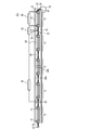
- FIG. 3A is a diagram showing a relay optical system in Example 1
- FIG. 3B is a diagram showing a unit.
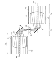
- FIG. 4A and FIG. 4B are diagrams showing the irradiation optical system in the first embodiment.
- FIG. 5A and FIG. 5B are diagrams showing a relay optical system according to the first embodiment and its first modification.
- FIG. 6 is a diagram illustrating a final-stage unit in the second modification of the first embodiment.
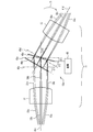
- FIG. 7 is a diagram showing a bending mechanism between units in the second embodiment.
- FIG. 1A is a block diagram of the image display device according to the first embodiment
- FIG. 1B is a diagram showing an irradiation optical system mounted on the head.
- FIG. 2 is
- FIG. 8 is a perspective view showing a bending mechanism between units in the second embodiment.
- FIG. 9 is a diagram showing a bending mechanism between units in the first modification of the second embodiment.
- FIG. 10 is a diagram illustrating a relay optical system according to the third embodiment.
- FIG. 11 is a diagram illustrating a bending mechanism of the relay optical system according to the fourth embodiment.
- FIG. 12A and FIG. 12B are diagrams showing a relay optical system in Example 5 and Modification 1 thereof.
- FIG. 13 is a diagram illustrating an irradiation optical system according to Modification 2 of Example 5.
- FIG. 1A is a block diagram of the image display device according to the first embodiment.
- an image display device 100 is a Maxwell's image display device that directly irradiates a retina with a light beam such as a laser beam, and includes a relay optical system 10 and an irradiation optical system 20.
- the projection device 30 is a mobile device such as a smart phone or a pico projector having a pico projector function.
- the light beam 50 emitted from the projection device 30 is two-dimensionally scanned. When the scanned light beam 50 is projected on a wall or the like, an image is projected on the wall.
- the relay optical system 10 can be attached to and detached from the projection device 30 by the attachment/detachment mechanism 31.
- the scanned light beam 50 is incident on the relay optical system 10.
- the light beam 52 emitted from the relay optical system 10 enters the irradiation optical system 20.
- the irradiation optical system 20 irradiates the eyeball 70 of the user with the light ray 59 that reflects the light ray 52.
- Each optical axis of the light ray 59 converges on the lens 72 in the eyeball 70 or in the vicinity thereof, and then is irradiated on the retina 74.
- FIG. 1B is a diagram showing the irradiation optical system mounted on the head in the first embodiment.
- the irradiation optical system 20 is attached to the spectacle frame 78.
- the irradiation optical system 20 is mounted on the user's head 76.
- a projection device 30 is connected to the irradiation optical system 20 via the relay optical system 10.
- FIG. 2 is a block diagram of the projection device according to the first embodiment.
- the projection device 30 includes a scanning mechanism 32, a light source 33, a control circuit 34, and an input circuit 35.
- Image data is input to the input circuit 35 from a camera and/or a recording device inside or outside the projection device 30.
- the input circuit 35 converts the input image data and outputs it to the control circuit 34.
- the control circuit 34 controls the light source 33 and the scanning mechanism 32 based on the image data.
- a processor such as a CPU (Central Processing Unit) may perform processing in cooperation with a program.
- the control circuit 34 may be a circuit designed exclusively.
- the light source 33 emits, for example, a red laser light (wavelength: about 610 nm to 660 nm), a green laser light (wavelength: about 515 nm to 540 nm) and a blue laser light (wavelength: about 440 nm to 480 nm) as the light beam 51.
- a red laser light wavelength: about 610 nm to 660 nm
- a green laser light wavelength: about 515 nm to 540 nm
- a blue laser light wavelength: about 440 nm to 480 nm
- RGB red, green, blue
- the light source 33 is one light source and may emit laser light of a single wavelength.
- the scanning mechanism 32 is, for example, a MEMS (Micro Electro Mechanical Systems) and scans the light beam 51 two-dimensionally.
- the scanned light ray 50 has a diffused optical axis of the scanned light rays 50a, 50b and 50c and each light ray is substantially parallel.
- Rays 50a, 50b and 50c represent rays of scanned ray 50 at different times.
- the light rays 50a, 50b and 50c are emitted from the projection device 30.
- Each of the light rays 50a, 50b, and 50c is a substantially parallel light, but is a light that converges slightly.
- Focusing-free images are projected at arbitrary screen positions by gently diffusing each of the light rays 50a, 50b, and 50c from a distance of several 100 mm or more, which is a focus position.
- the scanning mechanism 32 may be a polygon mirror or the like.
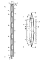
- FIG. 3A is a diagram showing a relay optical system in the first embodiment.
- the relay optical system 10 includes a plurality of multi-stage units 11.
- the plurality of units 11 are provided in the housing 15.
- the light beam 50 emitted from the scanning mechanism 32 enters the first-stage unit 11 of the relay optical system 10.
- the light beam emitted by the unit 11 of the previous stage enters the unit 11 of the next stage.
- the light beam 52 emitted from the unit 11 at the final stage enters the irradiation optical system 20.
- the light ray 59 emitted by the irradiation optical system 20 converges on a virtual converging surface 66 in the eyeball 70.
- Each unit 11 comprises optical components 12 and 13.
- a virtual converging surface 60 on which the scanned light beam converges exists between the unit 11 at the first stage and the unit 11 adjacent thereto.
- FIG. 3B is a diagram showing a unit.
- Rays 53a, 53b and 53c are rays of the scanned ray at different times.
- the straight line at the center indicates the optical axis of the ray
- the straight lines on both sides indicate the ends of the ray.
- the distance between the straight lines on both sides corresponds to the diameter of the light beam.
- the unit 11 includes optical components 12 and 13.
- the optical components 12 and 13 are, for example, convex lenses, which are infinite lenses. If the light ray 52 is of multiple colors (eg RGB), the optical components 12 and 13 should be a resin diffractive lens, a doubled, or a multi-group lens sized to be used in smart phone cameras to minimize chromatic aberration. Is preferred.
- the converging surface 60a is the converging surface 60 between the unit 11 at the preceding stage.
- the converging surface 60a corresponds to the scanning mechanism 32 of the projection device 30.
- the converging surface 60b is the converging surface 60 between the unit 11 of the next stage.
- the converging surface 60b corresponds to the converging surface with the irradiation optical system 20 or the converging surface 66 in the eyeball 70.
- the optical axes of the scanned light rays 53a, 53b and 53c and the optical axes of 55a, 55b and 55c converge, and the respective light rays 53a, 53b and 53c and 55a, 55b and 55c are substantially parallel.
- the converging surfaces 60a and 60b are in a conjugate relationship with each other through the unit 11, for example, a conjugate relationship of approximately equal magnification.
- the optical axes of the light rays 53a, 53b and 53c entering the optical component 12 from the converging surface 60a are diffused with each other and the respective light rays 53a, 53b and 53c are substantially parallel light.
- the optical component 12 converts the light rays 53a, 53b and 53c into the light rays 54a, 54b and 54c.
- the optical axes of the light rays 54a, 54b, and 54c are substantially parallel to each other, and the light rays 54a, 54b, and 54c are converged light up to the focal point 61 immediately after exiting the optical component 12.
- Each ray 54a, 54b and 54c forms a focal point 61 between the optical components 12 and 13.
- optical axes of the light rays 54a, 54b and 54c incident on the optical component 13 are substantially parallel to each other and each light ray 54a, 54b and 54c is diffuse light.
- Optical component 13 transforms rays 54a, 54b and 54c into rays 55a, 55b and 55c.
- the optical axes of the light rays 55a, 55b and 55c converge with each other and each light ray 55a, 55b and 55c is substantially parallel light.
- the relay optical system 10 can emit the light beam 52 at the same viewing angle as that of the light beam 50 emitted by the projection device 30.
- the projection device 30 when the projection device 30 is stored in the chest pocket of the user, the projection device 30 can be connected to the head irradiation optical system 20 by using the relay optical system 10 having a length of about 30 cm.
- the number of units 11 is about five. The number and length of the units 11 can be set appropriately.
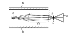
- FIGS. 4A and 4B are diagrams showing the irradiation optical system in the first embodiment.
- FIG. 4B is an enlarged view of FIG.
- the irradiation optical system 20 includes an optical system 21 and an optical system 25.
- the optical system 21 includes curved mirrors 22 and 24 and a plane mirror 23.
- the reflective surfaces of the curved mirrors 22 and 24 are curved surfaces such as free curved surfaces.
- the outer shape of the curved mirror 22 is larger than that of the curved mirror 24.
- the reflecting surface of the plane mirror 23 is substantially flat.
- the optical system 25 includes a curved mirror 26 and a curved mirror 28.
- the reflecting surfaces of the curved mirrors 26 and 28 are curved surfaces such as free curved surfaces.
- the outer shape of the curved mirror 28 is larger than that of the curved mirror 26.
- the curved mirrors 22 and 28 have the same curved shape, for example.
- the curved mirrors 24 and 26 have the same curved shape, for example. Accordingly, the curved mirrors 22 and 28 and the curved mirrors 24 and 26 have, for example, substantially the same focal length.
- the curved mirrors 22 and 28 are arranged at positions symmetrical with respect to the convergent surface 65, and the curved mirrors 24 and 26 are arranged at symmetrical positions with respect to the convergent surface 65.
- the converging surface 64 is a converging surface between the relay optical system 10 and the irradiation optical system 20, and the converging surface 66 is a converging surface within the eyeball 70.
- the optical axes of the light rays 52a, 52b, and 52c emitted from the relay optical system 10 converge on the converging surface 64.
- Each of the light rays 52a, 52b and 52c is substantially parallel light.
- the optical axes of the light rays 56a, 56b and 56c reflected by the curved mirror 22 are substantially parallel to each other and the respective light rays 56a, 56b and 56c are convergent light.
- a plane mirror 23 is provided for the purpose of bending the optical path.
- the optical axes of the light rays 57a, 57b and 57c reflected by the curved mirror 24 are converged with each other and the respective light rays 57a, 57b and 57c are substantially parallel light rays.
- the rays 57a, 57b and 57c converge at the converging surface 65.
- the optical axes of the light rays 58a, 58b and 58c reflected by the curved mirror 26 are substantially parallel to each other, and the respective light rays 58a, 58b and 58c are convergent light.
- the light rays 58a, 58b and 58c are focused at the focal point 67b.
- the optical axes of the light rays 59a, 59b and 59c reflected by the curved mirror 28 converge with each other and the respective light rays 59a, 59b and 59c are substantially parallel light.
- the optical axes of the rays 59a, 59b and 59c converge at a converging plane 66 in the eye 70 and each ray 59a, 59b and 59c is substantially focused at the retina 74.
- the converging surfaces 64 and 65 are in a unity conjugate relationship via the optical system 21, and the converging surfaces 65 and 66 are in a unity conjugate relationship via the optical system 25. As a result, the converging surfaces 64 and 66 have a unity-scale conjugate relationship. Since the scanning mechanism 32 and the converging surface 64 are in the same-magnification conjugate relationship via the relay optical system 10, the scanning mechanism 32 and the converging surface 66 are in the same-magnification conjugate relationship via the relay optical system 10 and the irradiation optical system 20. Becomes Thereby, the image projected by the projection device 30 can be projected on the retina 74.
- the scanning mechanism and its drive circuit are mounted on the head unit to be mounted on the user's head as in Patent Document 1, the head unit becomes large.
- countermeasures for radiation of electromagnetic waves from the head unit and/or countermeasures for heat radiation are taken. This further increases the size of the head unit and increases the number of parts. Therefore, the manufacturing process is lengthened and complicated. Further, the scanning mechanism and the driving circuit will be uniquely designed. This increases development costs.
- the light source on the head unit makes the head unit even larger. Therefore, if the light source is mounted on a part other than the head unit, the light source and the head unit are connected by an optical fiber. In this case, it becomes difficult to attach and detach the head unit and the unit equipped with the light source.
- the projection device 30 that projects an image by scanning the light beam 50 is used.
- the relay optical system 10 is attachable to and detachable from the projection device 30, and includes a plurality of units 11 that are optically connected in multiple stages.
- the light beam 50 emitted from the projection device 30 is incident on the first stage unit, and The emitted light beam is incident on the next unit.
- the irradiation optical system 20 is attached to the user's head 76, and irradiates the user's retina 74 with the light beam 52 emitted by the final stage unit 11 of the relay optical system 10.
- Each unit of the relay optical system 10 includes an optical component 12 (first optical component) and an optical component 13 (second optical component).
- the optical component 12 converts light rays 53a, 53b, and 53c whose optical axes are diffused into each other and whose light rays are substantially parallel to each other into light rays 54a, 54b, and 54c whose optical axes are substantially parallel and whose light rays are convergent light. To do.
- the optical component 13 converts the light rays 54a, 54b, and 54c emitted from the optical component 12 into light rays 55a, 55b, and 55c whose optical axes are converged to each other and which are substantially parallel rays.
- the light ray 50 emitted from the projection device 30 can be applied to the retina 74 as the light ray 59.
- the scanning mechanism 32 or the like may not be attached to the head 76. Therefore, the unit mounted on the head 76 can be downsized. Further, since no countermeasure against electromagnetic radiation and/or heat radiation is required, the unit mounted on the head 76 can be made smaller. Since the number of parts can be reduced, the manufacturing process can be shortened and simplified. Further, since the existing projection device 30 is used as the scanning mechanism and the driving circuit, the development cost can be suppressed. Further, since the light source 33 is provided in the projection device 30, the relay optical system 10 and the projection device 30 can be attached and detached. The optical axes of the light rays being substantially parallel and the light rays being substantially parallel light may be substantially parallel light and substantially parallel light so that the image emitted by the projection device 30 can be projected on the retina 74.
- the irradiation optical system 20 converts the light ray 52 emitted from the relay optical system 10 into a light ray 59 whose optical axis is converged into the eyeball 70 of the user and is substantially parallel light. Thereby, an image can be projected on the user's retina.
- the scanning mechanism 32 that scans the light beam in the projection device 30 and the converging surface 66 where the optical axis of the light beam converges in the eyeball 70 are in a conjugate relationship via the relay optical system 10 and the irradiation optical system 20. Thereby, an image can be projected on the user's retina.
- the optical axis of the light beam emitted by the unit 11 in the previous stage converges between the unit 11 in the previous stage and the unit 11 in the next stage. Thereby, the light beam can be relayed by the unit 11.
- the converging surface 60a where the optical axis of the light beam converges in front of each unit 11 and the converging surface 60b where the optical axis of the light beam converges after each unit 11 have a conjugate relationship via each unit 11. Thereby, the light beam can be relayed by the unit 11.
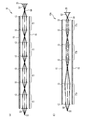
- FIG. 5A and FIG. 5B are diagrams showing a relay optical system according to the first embodiment and its first modification.
- each unit 11 of the relay optical system 10 is a unit-magnification optical system.
- the converging surface 64 between the relay optical system 10 and the irradiation optical system 20 and the scanning mechanism 32 have a conjugate relationship of 1 ⁇ through the relay optical system 10.
- the relay optical system 10a includes a plurality of units 11a, 11b and 11c.
- the units 11a, 11b and 11c include optical components 12 and 13, respectively.
- the unit 11b is a unit magnification optical system, but the units 11a and 11c are not unit magnification optical systems.
- the unit 11a is a 1/2 ⁇ optical system, and the unit 11c is a 2 ⁇ optical system.
- the unit 11a doubles the viewing angle and doubles the diameter of the light beam.
- the unit 11c doubles the viewing angle and halves the diameter of the light beam.
- the scanning mechanism 32 and the converging surface 64 have a unity-scale conjugate relationship via the relay optical system 10.
- the other configuration is the same as that of the first embodiment, and the description is omitted.
- each unit 11 of the plurality of units 11 of the relay optical system 10 is a unit magnification optical system. This facilitates the design of the relay optical system 10.
- At least one of the plurality of units 11a, 11b, and 11c of the relay optical system 10 is not a unit magnification optical system.
- the distance between the units 11a, 11b and 11c and the length of the units 11a, 11b and 11c can be freely set.
- the number of units 11a, 11b, and 11c in the first modification of the first embodiment can be smaller than that in the first embodiment.
- other optical components for example, a plane mirror or a half mirror
- FIG. 6 is a diagram illustrating a final-stage unit in the second modification of the first embodiment.
- the unit 11d at the final stage is not an equal-magnification optical system, but an enlargement optical system, for example.
- NA of the optical components 12 and/or 13 is different from that of other units.
- the units 11 other than the unit 11d at the final stage are equal-magnification optical systems.
- the beam diameter of the light beam 50 emitted from the projection device 30 is 1.0 mm and the viewing angle is 40°, and the unit 11d is a double optical system
- the beam diameter of the light beam 52 emitted from the relay optical system 10 is The viewing angle can be set to about 80° with a thickness of 0.5 mm.
- the other configuration is the same as that of the first embodiment, and the description is omitted.
- the relay optical system 10 may be a unit-magnification optical system, as in the first embodiment and its first modification. As in the second modification of the first embodiment, the relay optical system 10 may not be a unity magnification optical system. Similarly, the irradiation optical system 20 may be a 1 ⁇ optical system, and the relay optical system 10 may not be a 1 ⁇ optical system.
- Example 2 is an example in which the relay optical system 10 can be bent between the units 11.
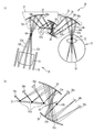
- FIG. 7 is a diagram showing a bending mechanism between units in the second embodiment
- FIG. 8 is a perspective view showing a bending mechanism between units in the second embodiment.
- Each line of ray 55 in FIG. 7 represents the optical axis of the ray of the scanned ray at different times.
- Ray 55 in FIG. 8 represents a bundle of scanned rays.
- a bending mechanism 16 is provided between the unit 11a at the front stage and the unit 11b at the rear stage.
- the bending mechanism 16 has plane mirrors 40 and 42.
- the light ray 55 emitted from the optical component 13 of the unit 11a is reflected by the plane mirror 40.
- the optical axis of the light ray 55 converges on the converging surface 68.
- the optical axes of the rays 55 then diffuse into each other and are reflected by the plane mirror 42.
- the light ray 55 then enters the optical component 12 of the unit 11b.
- the plane mirror 40 is inclined 45° with respect to the optical axis 41a of the unit 11a
- the plane mirror 42 is inclined 45° with respect to the optical axis 41b of the unit 11b.
- the bending mechanism 16 rotates the unit 11b and the plane mirror 42 with respect to the unit 11a and the plane mirror 40 about the central axis of the converging surface 68. Thereby, the units 11a and 11b can be bent.
- the rotation angle of the arrow 69 can be set arbitrarily, but it is preferable that the rotation angle is at intervals of 90° in order to prevent the image from tilting. For example, a rotation restraint mechanism is provided for every 90° of rotation angle.
- the other configuration is the same as that of the first embodiment, and the description is omitted.
- FIG. 9 is a diagram showing a bending mechanism between units in the first modification of the second embodiment.
- a bending mechanism 18 is provided between the unit 11a at the front stage and the unit 11b at the rear stage.
- the bending mechanism 18 has half mirrors 44 and 46.
- the light ray 55 emitted from the optical component 13 of the unit 11 a passes through the half mirror 44 and is reflected by the half mirror 46. After that, the light ray 55 is reflected by the half mirror 44, passes through the half mirror 46, and enters the optical component 12 of the unit 11b.
- the plane 45a orthogonal to the optical axis 41a and the plane 45b orthogonal to the optical axis 41b are substantially parallel to each other.
- the optical axis 41b of the unit 11b is inclined by the angle ⁇ 0 with respect to the optical axis 41a of the unit 11a as indicated by the arrow 69
- the half mirror 44 is inclined by the angle ⁇ 1 in the same direction as the arrow 69 with respect to the plane 45a.
- the half mirror 46 is tilted by an angle ⁇ 2 in the direction opposite to the arrow 69 with respect to the plane 45b.
- the angle ⁇ 1 is approximately the angle ⁇ 0, and the angle ⁇ 2 is approximately half the angle ⁇ 0. Thereby, the units 11a and 11b can be bent at an arbitrary angle.
- the other configuration is the same as that of the first embodiment, and the description is omitted.
- the relay optical system 10 includes the bending mechanisms 16 and 18 (changed) that change the angle formed by the optical axes 41a and 41b of two adjacent units 11a and 11b of the plurality of units 11. Mechanism). Thereby, the shape of the relay optical system 10 can be arbitrarily changed.
- FIG. 10 is a diagram showing a relay optical system according to the third embodiment.
- the relay optical system 10b includes a control unit 80, a half mirror 81, a detector 82, a dimming adjustment mechanism 83, dimming filters 84a and 84b, and a focus adjustment mechanism 86.
- the half mirror 81 separates a part of the light ray 54 passing through the relay optical system 10 as a light ray 85.
- the detector 82 detects the intensity of the light ray 85.
- the control unit 80 controls the dimming adjustment mechanism 83 based on the output signal of the detector 82.
- the detector 82 can detect the intensity of the light ray 54 passing through the relay optical system 10b by detecting the intensity of the light ray 85.
- the control unit 80 causes the dimming adjustment mechanism 83 to dimm the light beam 54 based on the intensity of the light beam 54 detected by the detector 82.
- the dimming adjustment mechanism 83 is, for example, a liquid crystal filter, and can change the dimming rate of the light ray 54. Further, the light ray 54 can be blocked.
- the dimming adjustment mechanism 83 adjusts the intensity of the light beam 54 so that the intensity of the light beam 54 passing through the relay optical system 10b does not exceed a predetermined value. With this, the intensity of the light beam 52 emitted from the relay optical system 10b can be appropriately adjusted, and thus the safety of the image display device can be improved.
- the control unit 80 and the dimming adjustment mechanism 83 may block the light beam 54 when the intensity of the light beam 54 exceeds a predetermined level. Further, the control unit 80 and the dimming adjustment mechanism 83 can also make the intensity of the light beam 54 almost constant by feedback controlling.
- the position where the detector 82 detects the intensity of the light beam 54 can be set to any position in the relay optical system 10b.
- the position where the dimming adjustment mechanism 83 is provided can be set to any position in the relay optical system 10b.
- the neutral density filters 84a and 84b have a constant neutral density ratio. Since the intensity of the light ray 54 can be limited also by providing one or a plurality of neutral density filters 84a and 84b, the safety of the image display device can be improved also by the neutral density filters 84a and 86b.
- the neutral density filters 84a and 84b can be provided between the units 11 and at arbitrary positions within the unit 11. Depending on the intensity of the light beam 54, the size of the relay optical system 10b, and the like, both the dimming adjustment mechanism and the dimming filter may be installed, or either one may be installed.
- the focus adjustment mechanism 86 adjusts the distance between the optical components 12 and 13.
- the light beam 50 emitted from the projection device 30 is substantially parallel light, but is focused at a distance (for example, 50 cm) equal to or greater than that of the relay optical system 10b.
- the focusing distance may vary depending on the projection device 30.
- a focus adjustment mechanism 86 that adjusts the distance between the optical components 12 and 13 in at least one unit of the plurality of units 11 is provided. This allows the light rays to be focused on the retina 74.
- the other configuration is the same as that of the first embodiment, and the description is omitted.
- the dimming adjustment mechanism 83, the dimming filters 84a and 84b, and the focus adjustment mechanism 86 can be provided in the first and second embodiments and their modifications.
- Example 4 is an example in which the relay optical system can be bent between the optical components 12 and 13 provided in one unit 11.
- FIG. 11 is a diagram illustrating a bending mechanism of the relay optical system according to the fourth embodiment.
- a bending mechanism 18a including half mirrors 44a and 46a arranged between the optical components 12 and 13 provided in one unit 11 and a mechanism 48 for tilting the half mirrors 44a and 46a. Equipped with.
- Light rays 54a to 54c emitted from the optical component 12 pass through the half mirror 44a and are reflected by the half mirror 46a. After that, the light rays 54a to 54c are reflected by the half mirror 44a, transmitted through the half mirror 46a, and incident on the optical component 13.
- the mechanism 48 sets the half mirror 44a at an angle ⁇ 0 in the same direction as the arrow 71 with respect to the plane 45c.
- the angle ⁇ 1 of substantially the same size is tilted.
- the mechanism 48 tilts the half mirror 46a with respect to the plane 45d in the direction opposite to the arrow 71 by an angle ⁇ 2 that is approximately half the angle ⁇ 0.
- the mechanism 48 tilts the half mirror 46a in the same direction as the arrow 71 with respect to the plane 45e orthogonal to the optical axis 41c by an angle ⁇ 3 that is approximately half the angle ⁇ 0.
- the optical component 12 and the optical component 13 can be bent at an arbitrary angle in one unit 11.
- a gear mechanism or a link mechanism can be used as the mechanism 48.
- the other configuration is the same as that of the first embodiment, and the description is omitted.
- the relay optical system includes the half mirrors 44a and 46a and the mechanism 48, and the bending mechanism 18a that changes the angle formed by the optical axis 41c of the optical component 12 and the optical axis 41d of the optical component 13 in one unit 11. (Change mechanism).
- the shape of the relay optical system can be arbitrarily changed.
- the bending mechanism 18 may include a mechanism 48 for inclining the half mirrors 44 and 46, as in the fourth embodiment.
- the mechanism 48 causes the half mirror 44 to form an angle substantially the same as the angle ⁇ 0 with respect to a plane orthogonal to the optical axis 41a. Tilt.
- the mechanism 48 tilts the half mirror 46 at an angle approximately half the angle ⁇ 0 with respect to the plane orthogonal to the optical axis 41a.
- the relay optical system is bent between the adjacent units 11a and 11b as an example.
- the present invention is not limited to this case, and the relay optical system may be bent between the optical components 12 and 13 in one unit 11 as in the fourth embodiment.
- the optical component 12 converts incident light rays 53a to 53c into light rays 54a to 54c whose optical axes are substantially parallel to each other and which are convergent light rays.
- the optical component 13 converts the light beams 54a to 54c emitted from the optical component 12 into light beams 55a to 55c whose optical axes are converged with each other and which are substantially parallel lights.
- the half mirrors 44 and 46 are arranged between the optical component 13 of the unit 11a and the optical component 12 of the unit 11b as in the first modification of the second embodiment, the half mirrors 44 and 46 have substantially parallel light. Rays of light are incident.
- the light rays that have passed through the half mirrors 44 and 46 without being reflected may be applied to the user's retina.
- the optical path length differs from that of the light ray traveling in the optical path of.
- the light rays incident on the half mirrors 44 and 46 are substantially parallel light, the light rays transmitted without being reflected by the half mirrors 44 and 46 are focused near the user's retina, and as a result, the light rays are transmitted to the user's retina.
- the desired image may not be projected well.
- the half mirrors 44a and 46a are arranged between the optical component 12 and the optical component 13 of one unit 11, the half mirrors 44a and 46a have converged light or diffused light rays. Is incident. A light ray that travels through a regular optical path that passes through the half mirror 44a, is reflected by the half mirror 46a, is then reflected by the half mirror 44a, and is transmitted through the half mirror 46a; The optical path length differs from that of the light ray traveling in the optical path of.
- the light rays incident on the half mirrors 44a and 46a are convergent light or diffused light, the light rays transmitted without being reflected by the half mirrors 44a and 46a are suppressed from being focused near the user's retina, As a result, a desired image can be favorably projected on the user's retina.
- the half mirror 46a be tilted about a line segment including a position where a light beam 54b located at the center of a plurality of light beams emitted from the optical component 12 is incident.
- the half mirror 46 is tilted depending on whether the optical axis 41d of the optical component 13 is tilted in the direction of the arrow 71 with respect to the optical axis 41c of the optical component 12 or the direction opposite to the arrow 71. Since it is inclined symmetrically, the relay optical system is easily bent.
- the light beam positioned in the center of the plurality of light beams emitted by the optical component 12 is a light beam positioned in the center of the image projected by the two-dimensionally scanned light beam, and is a light beam positioned in the center of the scanning range. is there.
- the half mirror 46 is the unit 11a. It is preferable that the optical component 13 is tilted about a line segment including a position where the optical axis of the light beam emitted from the optical component 13 is substantially converged. As a result, the expansion of the device size in the radial direction can be suppressed.
- each unit 11 of the relay optical system 10c is a unit magnification optical system.
- the unit 11b of the relay optical system 10d is a unit magnification optical system, but the units 11a and 11c are not unit magnification optical systems.
- the unit 11c is a 1/2 optical system, and the unit 11c is a 2 optical system.
- the optical axis of the light beam converges between the units 11 to 11c.
- An aperture 90 is provided having an opening through which the light rays pass.
- FIG. 13 is a diagram showing an irradiation optical system in Modification 2 of Example 5.
- the light rays pass through the converging surface where the optical axes of the light rays 52a to 52c emitted from the unit 11 at the final stage of the relay optical system 10 converge.
- An aperture 90 having an opening is provided.
- the aperture 90 may be provided on all the converging surfaces on which the optical axes of the light rays converge before or after the unit 11, but it may be provided on at least one converging surface.
- the aperture 90 may be an aperture having a fixed aperture diameter through which a light beam passes, or an aperture whose aperture diameter can be adjusted.
- At least one of the relay optical system and the irradiation optical system is a convergent optical axis of the light beam before or after at least one unit 11 among the plurality of units 11. It is preferable to provide an aperture 90 having an opening through which light rays pass.
- the aperture 90 allows the beam diameter of the light beam to be adjusted.
- the beam diameter of the light beam 50 emitted from the projection device 30 may be about 1 mm in diameter.
- the beam diameter of the light beam incident on the user's cornea tends to expand.
- the beam diameter of the light beam incident on the user's cornea be 0.8 mm or less. Therefore, in the fifth embodiment, the aperture 90 is arranged on the converging surface on which the optical axes of the light rays converge. Thereby, the beam diameter of the light beam can be adjusted, and the beam diameter of the light beam when entering the cornea of the user can be adjusted to an appropriate size to project a focus-free image.
Landscapes
- Engineering & Computer Science (AREA)
- Physics & Mathematics (AREA)
- General Physics & Mathematics (AREA)
- Computer Hardware Design (AREA)
- Theoretical Computer Science (AREA)
- Chemical & Material Sciences (AREA)
- Crystallography & Structural Chemistry (AREA)
- Multimedia (AREA)
- Signal Processing (AREA)
- Optics & Photonics (AREA)
Abstract
The present invention provides an image display device comprising: a relay optical system which can be attached to and detached from a projection device that projects an image by scanning light beams, and which comprises a plurality of units that are optically connected in multiple stages, the light beams emitted by the projection device being incident on the unit of the first stage and the light beams emitted from a unit in a previous stage being incident on the unit of the subsequent stage; and a beam-directing optical system which is mounted on the head of a user and directs the light beams emitted by the unit of the final stage of the relay optical system to the retina of the user, wherein each unit in the relay optical system includes a first optical component that converts incident light beams in which the optical axes of the beams spread apart from one another and the beams are each parallel light into light beams in which the optical axes of the beams are roughly parallel and the beams are each converging light, and a second optical component that converts the light beams emitted from the first optical component into light beams in which the optical axes of the beams converge together and the beams are each parallel light.
Description
本発明は、画像表示装置および中継光学系に関する。
The present invention relates to an image display device and a relay optical system.
ユーザの頭部に装着され、走査されたレーザ光をユーザの網膜に照射することで、網膜に画像を表示する画像表示装置が知られている(例えば特許文献1)。レーザ光を走査する走査系および走査系の駆動回路はユーザの頭部に装着される。
There is known an image display device that is mounted on a user's head and irradiates a user's retina with scanned laser light to display an image on the retina (for example, Patent Document 1). A scanning system for scanning laser light and a driving circuit for the scanning system are mounted on the head of a user.
しかしながら、走査系および駆動回路がユーザの頭部に装着されると、ユーザの頭部に装着するユニットが大きくなり、ユーザの負担となる。光線を複数の光学部品を備える中継光学系によって伝搬させようとすると、中継光学系は利便性向上のために屈曲可能であることが好ましい。
However, when the scanning system and the drive circuit are mounted on the user's head, the unit mounted on the user's head becomes large, which is a burden on the user. When a light beam is to be propagated by a relay optical system including a plurality of optical components, it is preferable that the relay optical system can be bent for convenience.
本発明は上記課題に鑑みなされたものであり、ユーザの頭部に装着するユニットを小型化することを目的とする。または、ユーザの頭部に装着するユニットの小型化にあたって、中継光学系の屈曲を可能とすることを目的とする。
The present invention has been made in view of the above problems, and an object of the present invention is to reduce the size of a unit worn on the head of a user. Alternatively, it is an object of the present invention to enable bending of the relay optical system when the unit mounted on the user's head is downsized.
本発明は、光線を走査することで画像を投影する投影装置に脱着可能であり、光学的に多段に接続された複数のユニットを備え、初段のユニットに前記投影装置が出射する光線が入射し、前段のユニットが出射した光線が次段のユニットに入射する中継光学系と、ユーザの頭部に装着され、前記中継光学系の最終段のユニットが出射した光線を前記ユーザの網膜に照射する照射光学系と、を備え、前記中継光学系の各ユニットは、光軸が互いに拡散しかつ各光線が略平行光である入射した光線を光軸が略平行でありかつ各光線が収束光である光線に変換する第1光学部品と、前記第1光学部品から出射された光線を光軸が互いに収束しかつ各光線が略平行光である光線に変換する第2光学部品と、を含む画像表示装置である。
INDUSTRIAL APPLICABILITY The present invention is detachable from a projection device that projects an image by scanning a light beam, and includes a plurality of units optically connected in multiple stages, and a light beam emitted by the projection device is incident on the first stage unit. , A relay optical system in which the light beam emitted from the unit in the previous stage is incident on the unit in the next stage, and the light beam emitted from the unit in the final stage of the relay optical system is emitted to the retina of the user. An irradiation optical system is provided, and each unit of the relay optical system has an optical axis that is substantially parallel to each other and an optical axis is substantially parallel to each other. An image including a first optical component that converts a certain light beam, and a second optical component that converts a light beam emitted from the first optical component into a light beam whose optical axes converge with each other and each light beam is substantially parallel light It is a display device.
上記構成において、前記照射光学系は、前記中継光学系が出射した光線を光軸が前記ユーザの眼球内に収束しかつ略平行光である光線に変換する構成とすることができる。
In the above configuration, the irradiation optical system may be configured to convert a light beam emitted by the relay optical system into a light beam whose optical axis converges into the eyeball of the user and is substantially parallel light.
上記構成において、前記投影装置内の光線を走査する走査機構と前記眼球において光線の光軸が収束する収束面とは前記中継光学系および前記照射光学系を介し共役関係にある構成とすることができる。
In the above configuration, the scanning mechanism that scans the light beam in the projection device and the converging surface where the optical axis of the light beam converges in the eyeball may have a conjugate relationship via the relay optical system and the irradiation optical system. it can.
上記構成において、前記前段のユニットが出射した光線の光軸は前記前段のユニットと前記次段のユニットとの間において収束する構成とすることができる。
In the above configuration, the optical axis of the light beam emitted from the preceding unit may be converged between the preceding unit and the following unit.
上記構成において、各ユニットの前において光線の光軸が収束する収束面と前記各ユニットの後において光線の光軸が収束する収束面とは前記各ユニットを介し共役関係にある構成とすることができる。
In the above configuration, the converging surface on which the optical axis of the light beam converges before each unit and the converging surface on which the optical axis of the light beam converges after each unit may have a conjugate relationship through the respective units. it can.
上記構成において、前記中継光学系の複数のユニットの各ユニットは等倍光学系である構成とすることができる。
In the above configuration, each unit of the plurality of units of the relay optical system may be a unit magnification optical system.
上記構成において、前記中継光学系の複数のユニットの少なくとも1つは等倍光学系でない構成とすることができる。
In the above configuration, at least one of the plurality of units of the relay optical system may not be a unit magnification optical system.
上記構成において、前記中継光学系は、前記複数のユニットのうち隣接する2つのユニットの光軸のなす角を変更する変更機構を備える構成とすることができる。
In the above configuration, the relay optical system may be configured to include a changing mechanism that changes an angle formed by optical axes of two adjacent units of the plurality of units.
上記構成において、前記中継光学系は、前記複数のユニットのうちの少なくとも1つのユニットにおける前記第1光学部品と前記第2光学部品の光軸のなす角を変更する変更機構を備える構成とすることができる。
In the above configuration, the relay optical system may include a changing mechanism that changes an angle formed by the optical axes of the first optical component and the second optical component in at least one unit of the plurality of units. You can
上記構成において、前記中継光学系は、前記複数のユニットのうち少なくとも1つのユニットにおける前記第1光学部品と前記第2光学部品との距離を調整する調整機構を備える構成とすることができる。
In the above configuration, the relay optical system may include an adjustment mechanism that adjusts a distance between the first optical component and the second optical component in at least one unit of the plurality of units.
上記構成において、前記中継光学系は、前記中継光学系を通過する光線の強度に基づき前記通過する光線の強度を調整する調整機構を備える構成とすることができる。
In the above configuration, the relay optical system may be configured to include an adjusting mechanism that adjusts the intensity of the light beam passing through the relay optical system based on the intensity of the light beam passing through the relay optical system.
上記構成において、前記中継光学系および前記照射光学系のうちの少なくとも一方は、前記複数のユニットのうちの少なくとも1つのユニットの前又は後において光線の光軸が収束する収束面に前記光線が通過する開口を有するアパーチャを備える構成とすることができる。
In the above configuration, at least one of the relay optical system and the irradiation optical system allows the light beam to pass through a converging surface on which an optical axis of the light beam converges before or after at least one unit of the plurality of units. It can be configured to include an aperture having an opening.
本発明は、光線を入射して出射する第1光学部品と、前記第1光学部品が出射した光線を入射して出射する第2光学部品と、第1ハーフミラーと、前記第1光学部品が出射して前記第1ハーフミラーを透過した光線を前記第1ハーフミラーに反射し、前記第1ハーフミラーで反射された光線を透過して前記第2光学部品に入射する第2ハーフミラーと、前記第1光学部品の第1光軸に対して前記第2光学部品の第2光軸が第1角度で傾いたときに、前記第1ハーフミラーを前記第1光軸に直交する第1平面に対して前記第1角度と同じ大きさの第2角度で傾かせ、前記第2ハーフミラーを前記第1光軸に直交する第2平面に対して前記第1角度の略半分の大きさの第3角度で傾かせる機構と、を備える中継光学系である。
The present invention provides a first optical component for entering and emitting a light beam, a second optical component for entering and emitting a light beam emitted by the first optical component, a first half mirror, and the first optical component. A second half mirror that emits a light beam that has passed through the first half mirror and reflects the light beam that is reflected by the first half mirror, and that transmits a light beam that is reflected by the first half mirror and that enters the second optical component. When the second optical axis of the second optical component is tilted at a first angle with respect to the first optical axis of the first optical component, the first half mirror is a first plane orthogonal to the first optical axis. With respect to the second angle, the second half mirror is tilted at a second angle having the same magnitude as the first angle, and the second half mirror is approximately half the first angle with respect to a second plane orthogonal to the first optical axis. And a mechanism for tilting at a third angle.
上記構成において、前記第1光学部品は、入射する光線を光軸が互いに略平行であり且つ各光線が収束光である光線に変換し、前記第2光学部品は、前記第1光学部品が出射する光線を光軸が互いに収束し且つ各光線が略平行光である光線に変換する構成とすることができる。
In the above configuration, the first optical component converts an incident light ray into a light ray whose optical axes are substantially parallel to each other and each light ray is a convergent light, and the second optical component outputs the first optical component. It is possible to adopt a configuration in which the rays to be converted are converted into rays in which the optical axes converge with each other and the rays are substantially parallel rays.
上記構成において、前記第2ハーフミラーは、前記第1光学部品が出射する複数の光線のうちの中央に位置する光線が入射する位置を含む線分を軸として傾く構成とすることができる。
In the above-mentioned configuration, the second half mirror may be configured to be tilted about a line segment including a position where a light beam located in the center among a plurality of light beams emitted from the first optical component enters.
上記構成において、前記第1光学部品は、入射する光線を光軸が互いに収束し且つ各光線が略平行光である光線に変換し、前記第2光学部品は、前記第1光学部品が出射する光線を光軸が互いに略平行であり且つ各光線が収束光である光線に変換する構成とすることができる。
In the above configuration, the first optical component converts incident light rays into light rays whose optical axes converge to each other and each light ray is substantially parallel light, and the second optical component emits light from the first optical component. A configuration can be adopted in which the light rays are converted into light rays whose optical axes are substantially parallel to each other and each light ray is a convergent light.
上記構成において、前記第2ハーフミラーは、前記第1光学部品が出射する光線の光軸が略収束する位置を含む線分を軸として傾く構成とすることができる。
In the above configuration, the second half mirror may be configured to be tilted about a line segment including a position where the optical axes of the light rays emitted from the first optical component are substantially converged.
本発明によれば、ユーザの頭部に装着するユニットを小型化することができる。または、中継光学系の屈曲を可能とすることができる。
According to the present invention, the unit mounted on the user's head can be downsized. Alternatively, it is possible to bend the relay optical system.
以下、図面を参照し、本発明の実施例について説明する。
An embodiment of the present invention will be described below with reference to the drawings.
図1(a)は、実施例1に係る画像表示装置のブロック図である。図1(a)に示すように、画像表示装置100は、レーザ光等の光線を網膜に直接照射するマックスウエル視型の画像表示装置であり、中継光学系10および照射光学系20を備えている。投影装置30は、例えばピコプロジェクタ機能を有するスマートホンまたはピコプロジェクタ等の携帯機器である。投影装置30が出射する光線50は二次元的に走査されている。走査された光線50が壁等に投影されると画像が壁に投影される。中継光学系10は、脱着機構31により投影装置30に脱着可能である。中継光学系10が投影装置30に装着されると、中継光学系10には走査された光線50が入射する。中継光学系10から出射された光線52は照射光学系20に入射する。照射光学系20は光線52を反射した光線59をユーザの眼球70に照射する。光線59の各光軸は眼球70内の水晶体72またはその付近で収束し、その後網膜74に照射される。
FIG. 1A is a block diagram of the image display device according to the first embodiment. As shown in FIG. 1A, an image display device 100 is a Maxwell's image display device that directly irradiates a retina with a light beam such as a laser beam, and includes a relay optical system 10 and an irradiation optical system 20. There is. The projection device 30 is a mobile device such as a smart phone or a pico projector having a pico projector function. The light beam 50 emitted from the projection device 30 is two-dimensionally scanned. When the scanned light beam 50 is projected on a wall or the like, an image is projected on the wall. The relay optical system 10 can be attached to and detached from the projection device 30 by the attachment/detachment mechanism 31. When the relay optical system 10 is mounted on the projection device 30, the scanned light beam 50 is incident on the relay optical system 10. The light beam 52 emitted from the relay optical system 10 enters the irradiation optical system 20. The irradiation optical system 20 irradiates the eyeball 70 of the user with the light ray 59 that reflects the light ray 52. Each optical axis of the light ray 59 converges on the lens 72 in the eyeball 70 or in the vicinity thereof, and then is irradiated on the retina 74.
図1(b)は、実施例1において頭部に装着された照射光学系を示す図である。図1(b)に示すように、照射光学系20は、眼鏡型フレーム78に装着されている。眼鏡型フレーム78をユーザの頭部76に装着すると、照射光学系20はユーザの頭部76に装着される。照射光学系20には、中継光学系10を介して投影装置30が接続される。
FIG. 1B is a diagram showing the irradiation optical system mounted on the head in the first embodiment. As shown in FIG. 1B, the irradiation optical system 20 is attached to the spectacle frame 78. When the eyeglass-type frame 78 is mounted on the user's head 76, the irradiation optical system 20 is mounted on the user's head 76. A projection device 30 is connected to the irradiation optical system 20 via the relay optical system 10.
図2は、実施例1における投影装置のブロック図である。投影装置30は、走査機構32、光源33、制御回路34および入力回路35を備えている。入力回路35には、投影装置30内または外のカメラおよび/または録画機器などから画像データが入力される。入力回路35は入力された画像データを変換し制御回路34に出力する。制御回路34は、画像データに基づき光源33および走査機構32を制御する。制御回路34は、例えばCPU(Central Processing Unit)等のプロセッサがプログラムと協働し処理を行ってもよい。制御回路34は、専用に設計された回路でもよい。
FIG. 2 is a block diagram of the projection device according to the first embodiment. The projection device 30 includes a scanning mechanism 32, a light source 33, a control circuit 34, and an input circuit 35. Image data is input to the input circuit 35 from a camera and/or a recording device inside or outside the projection device 30. The input circuit 35 converts the input image data and outputs it to the control circuit 34. The control circuit 34 controls the light source 33 and the scanning mechanism 32 based on the image data. In the control circuit 34, a processor such as a CPU (Central Processing Unit) may perform processing in cooperation with a program. The control circuit 34 may be a circuit designed exclusively.
光源33は、光線51として、例えば赤色レーザ光(波長:610nm~660nm程度)、緑色レーザ光(波長:515nm~540nm程度)および青色レーザ光(波長:440nm~480nm程度)を出射する。光源33には、例えばRGB(赤・緑・青)それぞれのレーザダイオードチップ、3色合成デバイスとマイクロコリメートレンズ、およびレーザダイオードを駆動するレーザドライバ回路とが集積されている。光源33は1つの光源であり単一の波長のレーザ光を出射してもよい。
The light source 33 emits, for example, a red laser light (wavelength: about 610 nm to 660 nm), a green laser light (wavelength: about 515 nm to 540 nm) and a blue laser light (wavelength: about 440 nm to 480 nm) as the light beam 51. In the light source 33, for example, RGB (red, green, blue) laser diode chips, a three-color combining device, a microcollimator lens, and a laser driver circuit for driving the laser diode are integrated. The light source 33 is one light source and may emit laser light of a single wavelength.
走査機構32は、例えばMEMS(Micro Electro Mechanical Systems)であり、光線51を2次元に走査する。走査された光線50は走査された光線50a、50bおよび50cの光軸は拡散しかつ各光線は略平行光である。光線50a、50bおよび50cは走査された光線50の異なる時間における光線を示している。光線50a、50bおよび50cは投影装置30から出射される。各光線50a、50bおよび50cは略平行光であるが、若干収束する光である。各光線50a、50bおよび50cが例えば合焦位置となる数100mm以上の距離から緩やかに拡散することで、任意のスクリーン位置でフォーカスフリーの画像が投影される。走査機構32は、ポリゴンミラー等でもよい。
The scanning mechanism 32 is, for example, a MEMS (Micro Electro Mechanical Systems) and scans the light beam 51 two-dimensionally. The scanned light ray 50 has a diffused optical axis of the scanned light rays 50a, 50b and 50c and each light ray is substantially parallel. Rays 50a, 50b and 50c represent rays of scanned ray 50 at different times. The light rays 50a, 50b and 50c are emitted from the projection device 30. Each of the light rays 50a, 50b, and 50c is a substantially parallel light, but is a light that converges slightly. Focusing-free images are projected at arbitrary screen positions by gently diffusing each of the light rays 50a, 50b, and 50c from a distance of several 100 mm or more, which is a focus position. The scanning mechanism 32 may be a polygon mirror or the like.
図3(a)は、実施例1における中継光学系を示す図である。図3(a)に示すように、中継光学系10は多段の複数のユニット11を備えている。複数のユニット11は筐体15内に設けられている。走査機構32から出射された光線50は中継光学系10の初段のユニット11に入射する。前段のユニット11が出射した光線は次段のユニット11に入射する。最終段のユニット11を出射した光線52は照射光学系20に入射する。照射光学系20が出射した光線59は眼球70内の仮想の収束面66において収束する。各ユニット11は光学部品12および13を備えている。初段のユニット11と隣接するユニット11の間には走査された光線が収束する仮想の収束面60が存在する。
FIG. 3A is a diagram showing a relay optical system in the first embodiment. As shown in FIG. 3A, the relay optical system 10 includes a plurality of multi-stage units 11. The plurality of units 11 are provided in the housing 15. The light beam 50 emitted from the scanning mechanism 32 enters the first-stage unit 11 of the relay optical system 10. The light beam emitted by the unit 11 of the previous stage enters the unit 11 of the next stage. The light beam 52 emitted from the unit 11 at the final stage enters the irradiation optical system 20. The light ray 59 emitted by the irradiation optical system 20 converges on a virtual converging surface 66 in the eyeball 70. Each unit 11 comprises optical components 12 and 13. A virtual converging surface 60 on which the scanned light beam converges exists between the unit 11 at the first stage and the unit 11 adjacent thereto.
図3(b)は、ユニットを示す図である。光線53a、53bおよび53cは走査された光線の異なる時間における光線である。各光線の3つの直線は、中心の直線が光線の光軸を示し、両側の直線が光線の端を示す。両側の直線の間隔が光線の径に相当する。以下の同様の図においても同様である。
FIG. 3B is a diagram showing a unit. Rays 53a, 53b and 53c are rays of the scanned ray at different times. Of the three straight lines of each ray, the straight line at the center indicates the optical axis of the ray, and the straight lines on both sides indicate the ends of the ray. The distance between the straight lines on both sides corresponds to the diameter of the light beam. The same applies to the following similar drawings.
図3(b)に示すように、ユニット11は光学部品12および13を備えている。光学部品12および13は例えば凸レンズであり、無限系のレンズである。光線52が複数の色(例えばRGB)からなる場合、光学部品12および13は、樹脂回折レンズ、ダブレッド、または、スマートホンのカメラに用いる程度のサイズの多群レンズを用い色収差を最小にすることが好ましい。
As shown in FIG. 3B, the unit 11 includes optical components 12 and 13. The optical components 12 and 13 are, for example, convex lenses, which are infinite lenses. If the light ray 52 is of multiple colors (eg RGB), the optical components 12 and 13 should be a resin diffractive lens, a doubled, or a multi-group lens sized to be used in smart phone cameras to minimize chromatic aberration. Is preferred.
収束面60aは前段のユニット11との間の収束面60である。ユニット11が初段の場合、収束面60aは投影装置30の走査機構32に相当する。収束面60bは次段のユニット11との間の収束面60である。ユニット11が最終段の場合、収束面60bは照射光学系20との間の収束面または眼球70内の収束面66に相当する。収束面60aおよび60bでは、走査された光線53a、53bおよび53cの光軸並びに55a、55bおよび55cの光軸が収束しており、各光線53a、53bおよび53c並びに55a、55bおよび55cは略平行光である。収束面60aと60bとはユニット11を介し共役の関係にあり、例えば略等倍の共役関係にある。
The converging surface 60a is the converging surface 60 between the unit 11 at the preceding stage. When the unit 11 is in the first stage, the converging surface 60a corresponds to the scanning mechanism 32 of the projection device 30. The converging surface 60b is the converging surface 60 between the unit 11 of the next stage. When the unit 11 is in the final stage, the converging surface 60b corresponds to the converging surface with the irradiation optical system 20 or the converging surface 66 in the eyeball 70. On the converging surfaces 60a and 60b, the optical axes of the scanned light rays 53a, 53b and 53c and the optical axes of 55a, 55b and 55c converge, and the respective light rays 53a, 53b and 53c and 55a, 55b and 55c are substantially parallel. Light. The converging surfaces 60a and 60b are in a conjugate relationship with each other through the unit 11, for example, a conjugate relationship of approximately equal magnification.
収束面60aから光学部品12に入射する光線53a、53bおよび53cの光軸は互いに拡散しかつ各光線53a、53bおよび53cは略平行光である。光学部品12は光線53a、53bおよび53cを光線54a、54bおよび54cに変換する。光線54a、54bおよび54cの光軸は互いに略平行でありかつ各光線54a、54bおよび54cは光学部品12を出射した直後は焦点61まで収束光である。各光線54a、54bおよび54cは光学部品12と13との間において焦点61を結ぶ。光学部品13に入射する光線54a、54bおよび54cの光軸は互いに略平行でありかつ各光線54a、54bおよび54cは拡散光である。光学部品13は光線54a、54bおよび54cを光線55a、55bおよび55cに変換する。光線55a、55bおよび55cの光軸は互いに収束しかつ各光線55a、55bおよび55cは略平行光である。
The optical axes of the light rays 53a, 53b and 53c entering the optical component 12 from the converging surface 60a are diffused with each other and the respective light rays 53a, 53b and 53c are substantially parallel light. The optical component 12 converts the light rays 53a, 53b and 53c into the light rays 54a, 54b and 54c. The optical axes of the light rays 54a, 54b, and 54c are substantially parallel to each other, and the light rays 54a, 54b, and 54c are converged light up to the focal point 61 immediately after exiting the optical component 12. Each ray 54a, 54b and 54c forms a focal point 61 between the optical components 12 and 13. The optical axes of the light rays 54a, 54b and 54c incident on the optical component 13 are substantially parallel to each other and each light ray 54a, 54b and 54c is diffuse light. Optical component 13 transforms rays 54a, 54b and 54c into rays 55a, 55b and 55c. The optical axes of the light rays 55a, 55b and 55c converge with each other and each light ray 55a, 55b and 55c is substantially parallel light.
ユニット11を複数設けることで、中継光学系10は、投影装置30が出射した光線50の視野角と同じ視野角で光線52を出射できる。例えば投影装置30をユーザの胸ポケットに収納したとき、長さが30cm程度の中継光学系10を用いれば、投影装置30を頭部の照射光学系20に接続できる。焦点距離等を考慮すると、ユニット11の個数は5個程度となる。ユニット11の個数および長さは、適宜設定可能である。
By providing a plurality of units 11, the relay optical system 10 can emit the light beam 52 at the same viewing angle as that of the light beam 50 emitted by the projection device 30. For example, when the projection device 30 is stored in the chest pocket of the user, the projection device 30 can be connected to the head irradiation optical system 20 by using the relay optical system 10 having a length of about 30 cm. Considering the focal length and the like, the number of units 11 is about five. The number and length of the units 11 can be set appropriately.
図4(a)および図4(b)は、実施例1における照射光学系を示す図である。図4(b)は、図4(a)の拡大図である。図4(a)および図4(b)に示すように、照射光学系20は、光学系21と光学系25を含む。光学系21は、曲面ミラー22、24および平面ミラー23を含む。曲面ミラー22および24の反射面は、自由曲面などの曲面である。曲面ミラー22の外形は曲面ミラー24よりも大きくなっている。平面ミラー23の反射面は略平面である。
4A and 4B are diagrams showing the irradiation optical system in the first embodiment. FIG. 4B is an enlarged view of FIG. As shown in FIGS. 4A and 4B, the irradiation optical system 20 includes an optical system 21 and an optical system 25. The optical system 21 includes curved mirrors 22 and 24 and a plane mirror 23. The reflective surfaces of the curved mirrors 22 and 24 are curved surfaces such as free curved surfaces. The outer shape of the curved mirror 22 is larger than that of the curved mirror 24. The reflecting surface of the plane mirror 23 is substantially flat.
光学系25は、曲面ミラー26と曲面ミラー28を含む。曲面ミラー26および28の反射面は、自由曲面などの曲面である。曲面ミラー28の外形は曲面ミラー26よりも大きくなっている。
The optical system 25 includes a curved mirror 26 and a curved mirror 28. The reflecting surfaces of the curved mirrors 26 and 28 are curved surfaces such as free curved surfaces. The outer shape of the curved mirror 28 is larger than that of the curved mirror 26.
曲面ミラー22と28は、例えば同じ曲面形状を有している。曲面ミラー24と26は、例えば同じ曲面形状を有している。これにより、曲面ミラー22と28、及び、24と26は、それぞれ例えば略同じ焦点距離を有する。曲面ミラー22と28は、収束面65を中心とした面対称の位置に配置され、曲面ミラー24と26は、収束面65を中心とした面対称の位置に配置されている。
The curved mirrors 22 and 28 have the same curved shape, for example. The curved mirrors 24 and 26 have the same curved shape, for example. Accordingly, the curved mirrors 22 and 28 and the curved mirrors 24 and 26 have, for example, substantially the same focal length. The curved mirrors 22 and 28 are arranged at positions symmetrical with respect to the convergent surface 65, and the curved mirrors 24 and 26 are arranged at symmetrical positions with respect to the convergent surface 65.
収束面64は中継光学系10と照射光学系20との間の収束面であり、収束面66は眼球70内の収束面である。中継光学系10から出射された光線52a、52bおよび52cの光軸は収束面64で収束する。各光線52a、52bおよび52cは略平行光である。曲面ミラー22で反射された光線56a、56bおよび56cの光軸は互いに略平行でありかつ各光線56a、56bおよび56cは収束光である。各光線を曲面ミラー24へ導くため、光路を屈曲させる目的で平面ミラー23が設けられている。
The converging surface 64 is a converging surface between the relay optical system 10 and the irradiation optical system 20, and the converging surface 66 is a converging surface within the eyeball 70. The optical axes of the light rays 52a, 52b, and 52c emitted from the relay optical system 10 converge on the converging surface 64. Each of the light rays 52a, 52b and 52c is substantially parallel light. The optical axes of the light rays 56a, 56b and 56c reflected by the curved mirror 22 are substantially parallel to each other and the respective light rays 56a, 56b and 56c are convergent light. In order to guide each light beam to the curved mirror 24, a plane mirror 23 is provided for the purpose of bending the optical path.
図4(b)において、曲面ミラー24で反射された光線57a、57bおよび57cの光軸は互いに収束しかつ各光線57a、57bおよび57cは略平行光である。光線57a、57bおよび57cは収束面65において収束する。曲面ミラー26で反射された光線58a、58bおよび58cの光軸は互いに略平行でありかつ各光線58a、58bおよび58cは収束光である。図4(b)に戻り、光線58a、58bよび58cは焦点67bにおいて合焦する。曲面ミラー28で反射された光線59a、59bおよび59cの光軸は互いに収束しかつ各光線59a、59bおよび59cは略平行光である。光線59a、59bおよび59cの光軸は眼球70内の収束面66において収束しかつ各光線59a、59bおよび59cはほぼ網膜74において合焦する。
In FIG. 4B, the optical axes of the light rays 57a, 57b and 57c reflected by the curved mirror 24 are converged with each other and the respective light rays 57a, 57b and 57c are substantially parallel light rays. The rays 57a, 57b and 57c converge at the converging surface 65. The optical axes of the light rays 58a, 58b and 58c reflected by the curved mirror 26 are substantially parallel to each other, and the respective light rays 58a, 58b and 58c are convergent light. Returning to FIG. 4B, the light rays 58a, 58b and 58c are focused at the focal point 67b. The optical axes of the light rays 59a, 59b and 59c reflected by the curved mirror 28 converge with each other and the respective light rays 59a, 59b and 59c are substantially parallel light. The optical axes of the rays 59a, 59b and 59c converge at a converging plane 66 in the eye 70 and each ray 59a, 59b and 59c is substantially focused at the retina 74.
収束面64と65とは光学系21を介し等倍の共役関係であり、収束面65と66とは光学系25を介し等倍の共役関係にある。これにより、収束面64と66とは等倍の共役関係にある。走査機構32と収束面64とは中継光学系10を介し等倍の共役関係にあることから、走査機構32と収束面66とは中継光学系10および照射光学系20を介し等倍の共役関係となる。これにより、投影装置30が投影した画像を網膜74に投影することができる。
The converging surfaces 64 and 65 are in a unity conjugate relationship via the optical system 21, and the converging surfaces 65 and 66 are in a unity conjugate relationship via the optical system 25. As a result, the converging surfaces 64 and 66 have a unity-scale conjugate relationship. Since the scanning mechanism 32 and the converging surface 64 are in the same-magnification conjugate relationship via the relay optical system 10, the scanning mechanism 32 and the converging surface 66 are in the same-magnification conjugate relationship via the relay optical system 10 and the irradiation optical system 20. Becomes Thereby, the image projected by the projection device 30 can be projected on the retina 74.
特許文献1のように、ユーザの頭部に装着する頭部ユニットに走査機構およびその駆動回路を搭載すると、頭部ユニットが大型化する。また、頭部ユニットからの電磁波の輻射対策および/または放熱対策を行うことなる。これにより、頭部ユニットはさらに大型化し、部品点数が多くなる。よって、製造工程の長大化および複雑化を招く。さらに、走査機構および駆動回路を独自に設計することになる。このため開発費用が増大する。
When the scanning mechanism and its drive circuit are mounted on the head unit to be mounted on the user's head as in Patent Document 1, the head unit becomes large. In addition, countermeasures for radiation of electromagnetic waves from the head unit and/or countermeasures for heat radiation are taken. This further increases the size of the head unit and increases the number of parts. Therefore, the manufacturing process is lengthened and complicated. Further, the scanning mechanism and the driving circuit will be uniquely designed. This increases development costs.
光源を頭部ユニットに搭載すると、頭部ユニットはさらに大型化する。そこで、光源を頭部ユニット以外に搭載すると、光源と頭部ユニットとを光ファイバで接続することになる。この場合、頭部ユニットと光源を搭載したユニットとの脱着が困難になる。
Mounting the light source on the head unit makes the head unit even larger. Therefore, if the light source is mounted on a part other than the head unit, the light source and the head unit are connected by an optical fiber. In this case, it becomes difficult to attach and detach the head unit and the unit equipped with the light source.
実施例1によれば、光線50を走査することで画像を投影する投影装置30を用いる。中継光学系10は、投影装置30に脱着可能であり、光学的に多段に接続された複数のユニット11を備え、初段のユニットに投影装置30が出射する光線50が入射し、前段のユニットが出射した光線が次段のユニットに入射する。照射光学系20は、ユーザの頭部76に装着され、中継光学系10の最終段のユニット11が出射した光線52をユーザの網膜74に照射する。中継光学系10の各ユニットは、光学部品12(第1光学部品)および光学部品13(第2光学部品)を含む。光学部品12は、光軸が互いに拡散しかつ各光線が略平行光である光線53a、53bおよび53cを光軸が略平行でありかつ各光線が収束光である光線54a、54bおよび54cに変換する。光学部品13は、光学部品12から出射された光線54a、54bおよび54cを光軸が互いに収束しかつ各光線が略平行光である光線55a、55bおよび55cに変換する。
According to the first embodiment, the projection device 30 that projects an image by scanning the light beam 50 is used. The relay optical system 10 is attachable to and detachable from the projection device 30, and includes a plurality of units 11 that are optically connected in multiple stages. The light beam 50 emitted from the projection device 30 is incident on the first stage unit, and The emitted light beam is incident on the next unit. The irradiation optical system 20 is attached to the user's head 76, and irradiates the user's retina 74 with the light beam 52 emitted by the final stage unit 11 of the relay optical system 10. Each unit of the relay optical system 10 includes an optical component 12 (first optical component) and an optical component 13 (second optical component). The optical component 12 converts light rays 53a, 53b, and 53c whose optical axes are diffused into each other and whose light rays are substantially parallel to each other into light rays 54a, 54b, and 54c whose optical axes are substantially parallel and whose light rays are convergent light. To do. The optical component 13 converts the light rays 54a, 54b, and 54c emitted from the optical component 12 into light rays 55a, 55b, and 55c whose optical axes are converged to each other and which are substantially parallel rays.
これにより、投影装置30が出射した光線50を光線59として網膜74に照射できる。頭部76に走査機構32等を装着しなくてもよい。よって、頭部76に装着するユニットを小型化できる。また、電磁波の輻射対策および/または放熱対策が不要なため、頭部76に装着するユニットをより小型化できる。部品点数を少なくできるため、製造工程の短縮および簡素化が可能となる。さらに、走査機構および駆動回路として既存の投影装置30を用いるため開発費用を抑制できる。さらに、光源33を投影装置30に設けるため、中継光学系10と投影装置30との脱着が可能となる。光線の光軸が略平行および各光線が略平行光とは、投影装置30が出射した画像が網膜74に投影できる程度に略平行および略平行光であればよい。
With this, the light ray 50 emitted from the projection device 30 can be applied to the retina 74 as the light ray 59. The scanning mechanism 32 or the like may not be attached to the head 76. Therefore, the unit mounted on the head 76 can be downsized. Further, since no countermeasure against electromagnetic radiation and/or heat radiation is required, the unit mounted on the head 76 can be made smaller. Since the number of parts can be reduced, the manufacturing process can be shortened and simplified. Further, since the existing projection device 30 is used as the scanning mechanism and the driving circuit, the development cost can be suppressed. Further, since the light source 33 is provided in the projection device 30, the relay optical system 10 and the projection device 30 can be attached and detached. The optical axes of the light rays being substantially parallel and the light rays being substantially parallel light may be substantially parallel light and substantially parallel light so that the image emitted by the projection device 30 can be projected on the retina 74.
照射光学系20は、中継光学系10が出射した光線52を光軸がユーザの眼球70内に収束しかつ略平行光である光線59に変換する。これにより、ユーザの網膜に画像を投影できる。
The irradiation optical system 20 converts the light ray 52 emitted from the relay optical system 10 into a light ray 59 whose optical axis is converged into the eyeball 70 of the user and is substantially parallel light. Thereby, an image can be projected on the user's retina.
投影装置30内の光線を走査する走査機構32と眼球70において光線の光軸が収束する収束面66とは中継光学系10および照射光学系20を介し共役関係にある。これにより、ユーザの網膜に画像を投影できる。
The scanning mechanism 32 that scans the light beam in the projection device 30 and the converging surface 66 where the optical axis of the light beam converges in the eyeball 70 are in a conjugate relationship via the relay optical system 10 and the irradiation optical system 20. Thereby, an image can be projected on the user's retina.
前段のユニット11が出射した光線の光軸は前段のユニット11と次段のユニット11との間において収束する。これにより、ユニット11により光線を中継できる。
The optical axis of the light beam emitted by the unit 11 in the previous stage converges between the unit 11 in the previous stage and the unit 11 in the next stage. Thereby, the light beam can be relayed by the unit 11.
各ユニット11の前において光線の光軸が収束する収束面60aと各ユニット11の後において光線の光軸が収束する収束面60bとは各ユニット11を介し共役関係にある。これにより、ユニット11により光線を中継できる。
The converging surface 60a where the optical axis of the light beam converges in front of each unit 11 and the converging surface 60b where the optical axis of the light beam converges after each unit 11 have a conjugate relationship via each unit 11. Thereby, the light beam can be relayed by the unit 11.
[実施例1の変形例1]
図5(a)および図5(b)は、実施例1およびその変形例1における中継光学系を示す図である。図5(a)に示すように、実施例1では、中継光学系10の各ユニット11は等倍光学系である。中継光学系10と照射光学系20との間の収束面64と、走査機構32とは中継光学系10を介し等倍の共役関係にある。 [Modification 1 of Embodiment 1]
FIG. 5A and FIG. 5B are diagrams showing a relay optical system according to the first embodiment and its first modification. As shown in FIG. 5A, in Example 1, eachunit 11 of the relay optical system 10 is a unit-magnification optical system. The converging surface 64 between the relay optical system 10 and the irradiation optical system 20 and the scanning mechanism 32 have a conjugate relationship of 1× through the relay optical system 10.
図5(a)および図5(b)は、実施例1およびその変形例1における中継光学系を示す図である。図5(a)に示すように、実施例1では、中継光学系10の各ユニット11は等倍光学系である。中継光学系10と照射光学系20との間の収束面64と、走査機構32とは中継光学系10を介し等倍の共役関係にある。 [Modification 1 of Embodiment 1]
FIG. 5A and FIG. 5B are diagrams showing a relay optical system according to the first embodiment and its first modification. As shown in FIG. 5A, in Example 1, each
図5(b)に示すように、実施例1の変形例1では、中継光学系10aは複数のユニット11a、11bおよび11cを備えている。ユニット11a、11bおよび11cは各々光学部品12および13を備えている。ユニット11bは等倍光学系であるが、ユニット11aおよび11cは等倍光学系ではない。ユニット11aは1/2倍光学系であり、ユニット11cは2倍光学系である。ユニット11aは視野角を1/2倍にし、光線の径を2倍とする。ユニット11cは視野角を2倍にし、光線の径を1/2倍にする。これにより、走査機構32と収束面64とは中継光学系10を介し等倍の共役関係となる。その他の構成は実施例1と同じであり説明を省略する。
As shown in FIG. 5B, in the first modification of the first embodiment, the relay optical system 10a includes a plurality of units 11a, 11b and 11c. The units 11a, 11b and 11c include optical components 12 and 13, respectively. The unit 11b is a unit magnification optical system, but the units 11a and 11c are not unit magnification optical systems. The unit 11a is a 1/2× optical system, and the unit 11c is a 2× optical system. The unit 11a doubles the viewing angle and doubles the diameter of the light beam. The unit 11c doubles the viewing angle and halves the diameter of the light beam. As a result, the scanning mechanism 32 and the converging surface 64 have a unity-scale conjugate relationship via the relay optical system 10. The other configuration is the same as that of the first embodiment, and the description is omitted.
実施例1のように、中継光学系10の複数のユニット11の各ユニット11は等倍光学系である。これにより、中継光学系10の設計が容易となる。
As in the first embodiment, each unit 11 of the plurality of units 11 of the relay optical system 10 is a unit magnification optical system. This facilitates the design of the relay optical system 10.
実施例1の変形例1のように、中継光学系10の複数のユニット11a、11bおよび11cの少なくとも1つは等倍光学系でない。これにより、各ユニット11a、11bおよび11c間の距離および各ユニット11a、11bおよび11cの長さを自由に設定できる。図5(a)および図5(b)の例では、実施例1の変形例1ではユニット11a、11bおよび11cの個数を実施例1より少なくできる。また、ユニット11aと11bとの間を長くできるため、この間に他の光学部品(例えば平面ミラーまたはハーフミラー)等を配置できる。このように、部品点数の削減、取り付け制度の緩和および/または形状の自由度を確保しやすくなる。
Like the first modification of the first embodiment, at least one of the plurality of units 11a, 11b, and 11c of the relay optical system 10 is not a unit magnification optical system. Thereby, the distance between the units 11a, 11b and 11c and the length of the units 11a, 11b and 11c can be freely set. In the example of FIGS. 5A and 5B, the number of units 11a, 11b, and 11c in the first modification of the first embodiment can be smaller than that in the first embodiment. Further, since the distance between the units 11a and 11b can be increased, other optical components (for example, a plane mirror or a half mirror) can be arranged between them. In this way, it becomes easy to reduce the number of parts, relax the mounting system, and/or secure the degree of freedom in shape.
[実施例1の変形例2]
図6は、実施例1の変形例2における最終段のユニットを示す図である。図6に示すように、最終段のユニット11dは等倍の光学系でなく、例えば拡大光学系である。例えば光学部品12および/または13の開口数NAが他のユニットと異なる。最終段のユニット11d以外のユニット11は等倍光学系である。これにより、投影装置30が出射する光線50の視野角に対し照射光学系20に出射する光線50の視野角を拡大または縮小できる。例えば投影装置30が出射する光線50のビーム径が1.0mmであり、視野角が40°のとき、ユニット11dを2倍光学系とすると、中継光学系10が出射する光線52のビーム径を0.5mmとし、視野角を80°程度とすることができる。その他の構成は実施例1と同じであり説明を省略する。 [Modification 2 of Embodiment 1]
FIG. 6 is a diagram illustrating a final-stage unit in the second modification of the first embodiment. As shown in FIG. 6, theunit 11d at the final stage is not an equal-magnification optical system, but an enlargement optical system, for example. For example, the numerical aperture NA of the optical components 12 and/or 13 is different from that of other units. The units 11 other than the unit 11d at the final stage are equal-magnification optical systems. Thereby, the viewing angle of the light ray 50 emitted to the irradiation optical system 20 can be expanded or reduced with respect to the viewing angle of the light ray 50 emitted from the projection device 30. For example, when the beam diameter of the light beam 50 emitted from the projection device 30 is 1.0 mm and the viewing angle is 40°, and the unit 11d is a double optical system, the beam diameter of the light beam 52 emitted from the relay optical system 10 is The viewing angle can be set to about 80° with a thickness of 0.5 mm. The other configuration is the same as that of the first embodiment, and the description is omitted.
図6は、実施例1の変形例2における最終段のユニットを示す図である。図6に示すように、最終段のユニット11dは等倍の光学系でなく、例えば拡大光学系である。例えば光学部品12および/または13の開口数NAが他のユニットと異なる。最終段のユニット11d以外のユニット11は等倍光学系である。これにより、投影装置30が出射する光線50の視野角に対し照射光学系20に出射する光線50の視野角を拡大または縮小できる。例えば投影装置30が出射する光線50のビーム径が1.0mmであり、視野角が40°のとき、ユニット11dを2倍光学系とすると、中継光学系10が出射する光線52のビーム径を0.5mmとし、視野角を80°程度とすることができる。その他の構成は実施例1と同じであり説明を省略する。 [Modification 2 of Embodiment 1]
FIG. 6 is a diagram illustrating a final-stage unit in the second modification of the first embodiment. As shown in FIG. 6, the
実施例1およびその変形例1のように、中継光学系10は等倍光学系でもよい。実施例1の変形例2のように、中継光学系10は等倍光学系でなくてもよい。同様に、照射光学系20は等倍光学系でもよく、中継光学系10は等倍光学系でなくてもよい。
The relay optical system 10 may be a unit-magnification optical system, as in the first embodiment and its first modification. As in the second modification of the first embodiment, the relay optical system 10 may not be a unity magnification optical system. Similarly, the irradiation optical system 20 may be a 1× optical system, and the relay optical system 10 may not be a 1× optical system.
実施例2は、中継光学系10をユニット11間において屈曲可能な例である。図7は、実施例2におけるユニット間の屈曲機構を示す図であり、図8は、実施例2におけるユニット間の屈曲機構を示す斜視図である。図7の光線55の各線は、走査された光線の異なる時間の光線の光軸を示す。図8の光線55は走査された光線の束を示す。図7および図8に示すように、前段のユニット11aと後段のユニット11bとの間に屈曲機構16が設けられている。屈曲機構16は、平面ミラー40および42を有している。ユニット11aの光学部品13から出射された光線55は平面ミラー40において反射される。光線55の光軸は収束面68において収束する。光線55の光軸はその後互いに拡散し平面ミラー42において反射される。その後光線55はユニット11bの光学部品12に入射する。
Example 2 is an example in which the relay optical system 10 can be bent between the units 11. FIG. 7 is a diagram showing a bending mechanism between units in the second embodiment, and FIG. 8 is a perspective view showing a bending mechanism between units in the second embodiment. Each line of ray 55 in FIG. 7 represents the optical axis of the ray of the scanned ray at different times. Ray 55 in FIG. 8 represents a bundle of scanned rays. As shown in FIGS. 7 and 8, a bending mechanism 16 is provided between the unit 11a at the front stage and the unit 11b at the rear stage. The bending mechanism 16 has plane mirrors 40 and 42. The light ray 55 emitted from the optical component 13 of the unit 11a is reflected by the plane mirror 40. The optical axis of the light ray 55 converges on the converging surface 68. The optical axes of the rays 55 then diffuse into each other and are reflected by the plane mirror 42. The light ray 55 then enters the optical component 12 of the unit 11b.
平面ミラー40はユニット11aの光軸41aに対し45°傾いており、平面ミラー42はユニット11bの光軸41bに対し45°傾いている。矢印69のように、屈曲機構16は、収束面68の中心軸を中心にユニット11bおよび平面ミラー42をユニット11aおよび平面ミラー40に対し回転させる。これにより、ユニット11aと11bとを屈曲させることができる。矢印69の回転角は任意に設定できるが、画像が傾斜することを抑制するため回転角は90°間隔であることが好ましい。例えば、回転角が90°ごとに回転抑止機構を設ける。その他の構成は実施例1と同じであり説明を省略する。
The plane mirror 40 is inclined 45° with respect to the optical axis 41a of the unit 11a, and the plane mirror 42 is inclined 45° with respect to the optical axis 41b of the unit 11b. As indicated by the arrow 69, the bending mechanism 16 rotates the unit 11b and the plane mirror 42 with respect to the unit 11a and the plane mirror 40 about the central axis of the converging surface 68. Thereby, the units 11a and 11b can be bent. The rotation angle of the arrow 69 can be set arbitrarily, but it is preferable that the rotation angle is at intervals of 90° in order to prevent the image from tilting. For example, a rotation restraint mechanism is provided for every 90° of rotation angle. The other configuration is the same as that of the first embodiment, and the description is omitted.
[実施例2の変形例1]
図9は、実施例2の変形例1におけるユニット間の屈曲機構を示す図である。図9に示すように、前段のユニット11aと後段のユニット11bとの間に屈曲機構18が設けられている。屈曲機構18は、ハーフミラー44および46を有している。ユニット11aの光学部品13から出射された光線55はハーフミラー44を透過し、ハーフミラー46において反射される。その後、光線55は、ハーフミラー44において反射され、ハーフミラー46を透過し、ユニット11bの光学部品12に入射する。 [Modification 1 of Embodiment 2]
FIG. 9 is a diagram showing a bending mechanism between units in the first modification of the second embodiment. As shown in FIG. 9, abending mechanism 18 is provided between the unit 11a at the front stage and the unit 11b at the rear stage. The bending mechanism 18 has half mirrors 44 and 46. The light ray 55 emitted from the optical component 13 of the unit 11 a passes through the half mirror 44 and is reflected by the half mirror 46. After that, the light ray 55 is reflected by the half mirror 44, passes through the half mirror 46, and enters the optical component 12 of the unit 11b.
図9は、実施例2の変形例1におけるユニット間の屈曲機構を示す図である。図9に示すように、前段のユニット11aと後段のユニット11bとの間に屈曲機構18が設けられている。屈曲機構18は、ハーフミラー44および46を有している。ユニット11aの光学部品13から出射された光線55はハーフミラー44を透過し、ハーフミラー46において反射される。その後、光線55は、ハーフミラー44において反射され、ハーフミラー46を透過し、ユニット11bの光学部品12に入射する。 [Modification 1 of Embodiment 2]
FIG. 9 is a diagram showing a bending mechanism between units in the first modification of the second embodiment. As shown in FIG. 9, a
ユニット11aの光軸41aとユニット11bの光軸41bとがほぼ一致するとき、光軸41aに直交する平面45aと光軸41bに直交する平面45bとはほぼ平行である。矢印69のように、ユニット11bの光軸41bがユニット11aの光軸41aに対し角度θ0傾いたとき、ハーフミラー44を平面45aに対し矢印69と同じ方向に角度θ1傾ける。ハーフミラー46を平面45bに対し矢印69と反対の方向に角度θ2傾ける。角度θ1を略角度θ0とし、角度θ2を角度θ0の略1/2とする。これにより、ユニット11aと11bとを任意の角度屈曲させることができる。その他の構成は実施例1と同じであり説明を省略する。
When the optical axis 41a of the unit 11a and the optical axis 41b of the unit 11b substantially coincide with each other, the plane 45a orthogonal to the optical axis 41a and the plane 45b orthogonal to the optical axis 41b are substantially parallel to each other. When the optical axis 41b of the unit 11b is inclined by the angle θ0 with respect to the optical axis 41a of the unit 11a as indicated by the arrow 69, the half mirror 44 is inclined by the angle θ1 in the same direction as the arrow 69 with respect to the plane 45a. The half mirror 46 is tilted by an angle θ2 in the direction opposite to the arrow 69 with respect to the plane 45b. The angle θ1 is approximately the angle θ0, and the angle θ2 is approximately half the angle θ0. Thereby, the units 11a and 11b can be bent at an arbitrary angle. The other configuration is the same as that of the first embodiment, and the description is omitted.
実施例2およびその変形例によれば、中継光学系10は、複数のユニット11のうち隣接する2つのユニット11aおよび11bの光軸41aおよび41bのなす角を変更する屈曲機構16および18(変更機構)を備える。これにより、中継光学系10の形状を任意に変更できる。
According to the second embodiment and its modification, the relay optical system 10 includes the bending mechanisms 16 and 18 (changed) that change the angle formed by the optical axes 41a and 41b of two adjacent units 11a and 11b of the plurality of units 11. Mechanism). Thereby, the shape of the relay optical system 10 can be arbitrarily changed.
図10は、実施例3における中継光学系を示す図である。図10に示すように、中継光学系10bは、制御部80、ハーフミラー81、検出器82、減光調整機構83、減光フィルタ84a、84bおよび焦点調整機構86を備えている。ハーフミラー81は中継光学系10を通過する光線54の一部を光線85として分離する。検出器82は、光線85の強度を検出する。制御部80は、検出器82の出力信号に基づき、減光調整機構83を制御する。
FIG. 10 is a diagram showing a relay optical system according to the third embodiment. As shown in FIG. 10, the relay optical system 10b includes a control unit 80, a half mirror 81, a detector 82, a dimming adjustment mechanism 83, dimming filters 84a and 84b, and a focus adjustment mechanism 86. The half mirror 81 separates a part of the light ray 54 passing through the relay optical system 10 as a light ray 85. The detector 82 detects the intensity of the light ray 85. The control unit 80 controls the dimming adjustment mechanism 83 based on the output signal of the detector 82.
検出器82は、光線85の強度を検出することで、中継光学系10bを通過する光線54の強度を検出できる。制御部80は検出器82が検出した光線54の強度に基づき減光調整機構83に光線54を減光させる。減光調整機構83は例えば液晶フィルタであり、光線54の減光率を変更できる。また、光線54を遮断できる。
The detector 82 can detect the intensity of the light ray 54 passing through the relay optical system 10b by detecting the intensity of the light ray 85. The control unit 80 causes the dimming adjustment mechanism 83 to dimm the light beam 54 based on the intensity of the light beam 54 detected by the detector 82. The dimming adjustment mechanism 83 is, for example, a liquid crystal filter, and can change the dimming rate of the light ray 54. Further, the light ray 54 can be blocked.
減光調整機構83は中継光学系10bを通過する光線54の強度が所定の値を越えないように光線54の強度を調整する。これにより、中継光学系10bが出射する光線52の強度を適切に調整できるので、画像表示装置の安全性を向上させることができる。制御部80および減光調整機構83は光線54の強度が所定以上となった場合には、光線54を遮断してもよい。また、制御部80および減光調整機構83は光線54の強度をフィードバック制御することでほぼ一定とすることもできる。検出器82が光線54の強度を検出する位置は、中継光学系10b内の任意の位置に設定できる。減光調整機構83を設ける位置は、中継光学系10b内の任意の位置に設定できる。
The dimming adjustment mechanism 83 adjusts the intensity of the light beam 54 so that the intensity of the light beam 54 passing through the relay optical system 10b does not exceed a predetermined value. With this, the intensity of the light beam 52 emitted from the relay optical system 10b can be appropriately adjusted, and thus the safety of the image display device can be improved. The control unit 80 and the dimming adjustment mechanism 83 may block the light beam 54 when the intensity of the light beam 54 exceeds a predetermined level. Further, the control unit 80 and the dimming adjustment mechanism 83 can also make the intensity of the light beam 54 almost constant by feedback controlling. The position where the detector 82 detects the intensity of the light beam 54 can be set to any position in the relay optical system 10b. The position where the dimming adjustment mechanism 83 is provided can be set to any position in the relay optical system 10b.
減光フィルタ84aおよび84bは一定の減光率を有する。1または複数の減光フィルタ84aおよび84bを設けることによっても、光線54の強度を制限することができるので、減光フィルタ84aおよび86bによっても画像表示装置の安全性を向上させることができる。ここで、減光フィルタ84aおよび84bはユニット11間およびユニット11内の任意の位置に設けることができる。光線54の強度や、中継光学系10bの大きさなどに応じて、減光調整機構および減光フィルタを両方設置してもよいし、いずれか一方を設置するようにしてもよい。
The neutral density filters 84a and 84b have a constant neutral density ratio. Since the intensity of the light ray 54 can be limited also by providing one or a plurality of neutral density filters 84a and 84b, the safety of the image display device can be improved also by the neutral density filters 84a and 86b. Here, the neutral density filters 84a and 84b can be provided between the units 11 and at arbitrary positions within the unit 11. Depending on the intensity of the light beam 54, the size of the relay optical system 10b, and the like, both the dimming adjustment mechanism and the dimming filter may be installed, or either one may be installed.
焦点調整機構86は光学部品12と13との間の距離を調整する。投影装置30が出射する光線50は略平行光であるが、中継光学系10bと同程度以上の距離(例えば50cm)において焦点を結ぶ。焦点を結ぶ距離は投影装置30により変わることがある。これにより、網膜74近傍の合焦位置が変わる。そこで、複数のユニット11のうち少なくとも1つのユニットにおける光学部品12と13との距離を調整する焦点調整機構86を設ける。これにより、光線を網膜74に合焦させることができる。
The focus adjustment mechanism 86 adjusts the distance between the optical components 12 and 13. The light beam 50 emitted from the projection device 30 is substantially parallel light, but is focused at a distance (for example, 50 cm) equal to or greater than that of the relay optical system 10b. The focusing distance may vary depending on the projection device 30. As a result, the focus position near the retina 74 changes. Therefore, a focus adjustment mechanism 86 that adjusts the distance between the optical components 12 and 13 in at least one unit of the plurality of units 11 is provided. This allows the light rays to be focused on the retina 74.
その他の構成は実施例1と同じであり説明を省略する。減光調整機構83、減光フィルタ84a、84bおよび焦点調整機構86は、実施例1、2およびその変形例に設けることもできる。
The other configuration is the same as that of the first embodiment, and the description is omitted. The dimming adjustment mechanism 83, the dimming filters 84a and 84b, and the focus adjustment mechanism 86 can be provided in the first and second embodiments and their modifications.
実施例4は、中継光学系が1つのユニット11に備わる光学部品12と光学部品13の間で屈曲可能な例である。図11は、実施例4における中継光学系の屈曲機構を示す図である。図11に示すように、1つのユニット11に備わる光学部品12と光学部品13の間に配置されたハーフミラー44aおよび46aと、ハーフミラー44aおよび46aを傾かせる機構48と、を含む屈曲機構18aを備える。光学部品12から出射された光線54a~54cは、ハーフミラー44aを透過し、ハーフミラー46aにおいて反射される。その後、光線54a~54cは、ハーフミラー44aにおいて反射され、ハーフミラー46aを透過し、光学部品13に入射する。
Example 4 is an example in which the relay optical system can be bent between the optical components 12 and 13 provided in one unit 11. FIG. 11 is a diagram illustrating a bending mechanism of the relay optical system according to the fourth embodiment. As shown in FIG. 11, a bending mechanism 18a including half mirrors 44a and 46a arranged between the optical components 12 and 13 provided in one unit 11 and a mechanism 48 for tilting the half mirrors 44a and 46a. Equipped with. Light rays 54a to 54c emitted from the optical component 12 pass through the half mirror 44a and are reflected by the half mirror 46a. After that, the light rays 54a to 54c are reflected by the half mirror 44a, transmitted through the half mirror 46a, and incident on the optical component 13.
光学部品12の光軸41cと光学部品13の光軸41dとがほぼ一致するとき、光軸41cに直交する平面45cと光軸41dに直交する平面45dとはほぼ平行である。矢印71のように、光学部品13の光軸41dが光学部品12の光軸41cに対し角度θ0傾いたとき、機構48はハーフミラー44aを平面45cに対して矢印71と同じ方向に角度θ0と略同じ大きさの角度θ1傾ける。また、機構48はハーフミラー46aを平面45dに対し矢印71と反対の方向に角度θ0の略半分の大きさの角度θ2傾ける。言い換えると、機構48はハーフミラー46aを光軸41cに直交する平面45eに対し矢印71と同じ方向に角度θ0の略半分の大きさの角度θ3傾ける。これにより、1つのユニット11内において光学部品12と光学部品13とを任意の角度屈曲させることができる。機構48は、例えばギア機構又はリンク機構などを用いることができる。その他の構成は実施例1と同じであり説明を省略する。
When the optical axis 41c of the optical component 12 and the optical axis 41d of the optical component 13 substantially coincide with each other, the plane 45c orthogonal to the optical axis 41c and the plane 45d orthogonal to the optical axis 41d are substantially parallel to each other. When the optical axis 41d of the optical component 13 is tilted at an angle θ0 with respect to the optical axis 41c of the optical component 12 as indicated by an arrow 71, the mechanism 48 sets the half mirror 44a at an angle θ0 in the same direction as the arrow 71 with respect to the plane 45c. The angle θ1 of substantially the same size is tilted. Further, the mechanism 48 tilts the half mirror 46a with respect to the plane 45d in the direction opposite to the arrow 71 by an angle θ2 that is approximately half the angle θ0. In other words, the mechanism 48 tilts the half mirror 46a in the same direction as the arrow 71 with respect to the plane 45e orthogonal to the optical axis 41c by an angle θ3 that is approximately half the angle θ0. Thereby, the optical component 12 and the optical component 13 can be bent at an arbitrary angle in one unit 11. As the mechanism 48, for example, a gear mechanism or a link mechanism can be used. The other configuration is the same as that of the first embodiment, and the description is omitted.
実施例4では、中継光学系は、ハーフミラー44aおよび46aと機構48を含み、1つのユニット11における光学部品12の光軸41cと光学部品13の光軸41dのなす角を変更する屈曲機構18a(変更機構)を備える。これにより、中継光学系の形状を任意に変更できる。
In the fourth embodiment, the relay optical system includes the half mirrors 44a and 46a and the mechanism 48, and the bending mechanism 18a that changes the angle formed by the optical axis 41c of the optical component 12 and the optical axis 41d of the optical component 13 in one unit 11. (Change mechanism). Thereby, the shape of the relay optical system can be arbitrarily changed.
図9で説明した実施例2の変形例1においても、実施例4と同様に、屈曲機構18は、ハーフミラー44および46を傾かせる機構48を含んでいてもよい。この場合、ユニット11bの光軸41bがユニット11aの光軸41aに対し角度θ0傾いたとき、機構48はハーフミラー44を光軸41aに直交する平面に対し角度θ0と略同じ大きさの角度で傾ける。機構48はハーフミラー46を光軸41aに直交する平面に対し角度θ0の略半分の大きさの角度で傾ける。
Also in the first modification of the second embodiment described with reference to FIG. 9, the bending mechanism 18 may include a mechanism 48 for inclining the half mirrors 44 and 46, as in the fourth embodiment. In this case, when the optical axis 41b of the unit 11b is inclined by an angle θ0 with respect to the optical axis 41a of the unit 11a, the mechanism 48 causes the half mirror 44 to form an angle substantially the same as the angle θ0 with respect to a plane orthogonal to the optical axis 41a. Tilt. The mechanism 48 tilts the half mirror 46 at an angle approximately half the angle θ0 with respect to the plane orthogonal to the optical axis 41a.
実施例2の変形例1では、図9のように、中継光学系が隣接するユニット11aおよび11bの間で屈曲する場合を例に示した。しかしながら、この場合に限られず、実施例4のように、中継光学系は1つのユニット11内の光学部品12と光学部品13の間で屈曲する場合でもよい。
In the first modification of the second embodiment, as shown in FIG. 9, the case where the relay optical system is bent between the adjacent units 11a and 11b is shown as an example. However, the present invention is not limited to this case, and the relay optical system may be bent between the optical components 12 and 13 in one unit 11 as in the fourth embodiment.
光学部品12は、入射する光線53a~53cを光軸が互いに略平行であり且つ各光線が収束光である光線54a~54cに変換する。光学部品13は、光学部品12が出射する光線54a~54cを光軸が互いに収束し且つ各光線が略平行光である光線55a~55cに変換する。実施例2の変形例1のように、ユニット11aの光学部品13とユニット11bの光学部品12との間にハーフミラー44、46が配置されている場合、ハーフミラー44、46には略平行光の光線が入射する。ユニット11aに対するユニット11bの傾きが小さい場合、ハーフミラー44、46を反射せずに透過した光線がユーザの網膜に照射されることがある。ハーフミラー44を透過してハーフミラー46で反射した後にハーフミラー44で反射されてハーフミラー46を透過する正規の光路を進む光線と、ハーフミラー44、46を反射せずにそのまま透過する非正規の光路を進む光線と、では光路長が異なる。しかしながら、ハーフミラー44、46に入射する光線が略平行光である場合では、ハーフミラー44、46を反射せずに透過した光線がユーザの網膜近傍で合焦し、その結果、ユーザの網膜に所望の画像を良好に投影できない場合がある。
The optical component 12 converts incident light rays 53a to 53c into light rays 54a to 54c whose optical axes are substantially parallel to each other and which are convergent light rays. The optical component 13 converts the light beams 54a to 54c emitted from the optical component 12 into light beams 55a to 55c whose optical axes are converged with each other and which are substantially parallel lights. When the half mirrors 44 and 46 are arranged between the optical component 13 of the unit 11a and the optical component 12 of the unit 11b as in the first modification of the second embodiment, the half mirrors 44 and 46 have substantially parallel light. Rays of light are incident. When the inclination of the unit 11b with respect to the unit 11a is small, the light rays that have passed through the half mirrors 44 and 46 without being reflected may be applied to the user's retina. A light ray that travels through a regular optical path that passes through the half mirror 44, is reflected by the half mirror 46, is then reflected by the half mirror 44, and is transmitted through the half mirror 46, and the non-regular ray that is directly transmitted without being reflected by the half mirrors 44, The optical path length differs from that of the light ray traveling in the optical path of. However, when the light rays incident on the half mirrors 44 and 46 are substantially parallel light, the light rays transmitted without being reflected by the half mirrors 44 and 46 are focused near the user's retina, and as a result, the light rays are transmitted to the user's retina. The desired image may not be projected well.
これに対し、実施例4では、1つのユニット11の光学部品12と光学部品13の間にハーフミラー44a、46aが配置されているため、ハーフミラー44a、46aには収束光又は拡散光の光線が入射する。ハーフミラー44aを透過してハーフミラー46aで反射した後にハーフミラー44aで反射されてハーフミラー46aを透過する正規の光路を進む光線と、ハーフミラー44a、46aを反射せずにそのまま透過する非正規の光路を進む光線と、では光路長が異なる。このため、ハーフミラー44a、46aに入射する光線が収束光又は拡散光である場合では、ハーフミラー44a、46aを反射せずに透過した光線はユーザの網膜近傍で合焦することが抑制され、その結果、ユーザの網膜に所望の画像を良好に投影することができる。
On the other hand, in the fourth embodiment, since the half mirrors 44a and 46a are arranged between the optical component 12 and the optical component 13 of one unit 11, the half mirrors 44a and 46a have converged light or diffused light rays. Is incident. A light ray that travels through a regular optical path that passes through the half mirror 44a, is reflected by the half mirror 46a, is then reflected by the half mirror 44a, and is transmitted through the half mirror 46a; The optical path length differs from that of the light ray traveling in the optical path of. Therefore, when the light rays incident on the half mirrors 44a and 46a are convergent light or diffused light, the light rays transmitted without being reflected by the half mirrors 44a and 46a are suppressed from being focused near the user's retina, As a result, a desired image can be favorably projected on the user's retina.
図11のように、ハーフミラー46aは、光学部品12が出射する複数の光線のうちの中央に位置する光線54bが入射する位置を含む線分を軸として傾くことが好ましい。これにより、光学部品12の光軸41cに対して光学部品13の光軸41dを矢印71の方向に傾かせた場合と矢印71とは反対側の方向に傾かせた場合とでハーフミラー46は対称に傾くようになるため、中継光学系の屈曲が行い易くなる。光学部品12が出射する複数の光線のうちの中央に位置する光線とは、二次元に走査された光線によって投影される画像の中央に位置する光線であり、走査範囲の中央に位置する光線である。
As shown in FIG. 11, it is preferable that the half mirror 46a be tilted about a line segment including a position where a light beam 54b located at the center of a plurality of light beams emitted from the optical component 12 is incident. As a result, the half mirror 46 is tilted depending on whether the optical axis 41d of the optical component 13 is tilted in the direction of the arrow 71 with respect to the optical axis 41c of the optical component 12 or the direction opposite to the arrow 71. Since it is inclined symmetrically, the relay optical system is easily bent. The light beam positioned in the center of the plurality of light beams emitted by the optical component 12 is a light beam positioned in the center of the image projected by the two-dimensionally scanned light beam, and is a light beam positioned in the center of the scanning range. is there.
実施例2の変形例1の図9のように、ハーフミラー44および46がユニット11aの光学部品13とユニット11bの光学部品12の間に配置されている場合では、ハーフミラー46は、ユニット11aの光学部品13が出射する光線の光軸が略収束する位置を含む線分を軸として傾くことが好ましい。これにより、特に径方向の装置サイズの拡大を抑制できる。
In the case where the half mirrors 44 and 46 are arranged between the optical component 13 of the unit 11a and the optical component 12 of the unit 11b as shown in FIG. 9 of the first modification of the second embodiment, the half mirror 46 is the unit 11a. It is preferable that the optical component 13 is tilted about a line segment including a position where the optical axis of the light beam emitted from the optical component 13 is substantially converged. As a result, the expansion of the device size in the radial direction can be suppressed.
図12(a)および図12(b)は、実施例5およびその変形例1における中継光学系を示す図である。図12(a)に示すように、実施例5では、中継光学系10cの各ユニット11が等倍光学系である。図12(b)に示すように、実施例5の変形例1では、中継光学系10dのユニット11bは等倍光学系であるが、ユニット11a及び11cは等倍光学系ではない、ユニット11aは1/2倍光学系であり、ユニット11cは2倍光学系である。
12(a) and 12(b) are diagrams showing a relay optical system in Example 5 and Modification 1 thereof. As shown in FIG. 12A, in Example 5, each unit 11 of the relay optical system 10c is a unit magnification optical system. As shown in FIG. 12B, in the modified example 1 of the fifth embodiment, the unit 11b of the relay optical system 10d is a unit magnification optical system, but the units 11a and 11c are not unit magnification optical systems. The unit 11c is a 1/2 optical system, and the unit 11c is a 2 optical system.
図12(a)および図12(b)に示すように、実施例5およびその変形例1における中継光学系10c、10dでは、ユニット11~11cの間で光線の光軸が収束する収束面に光線が通過する開口を有するアパーチャ90が設けられている。
As shown in FIGS. 12(a) and 12(b), in the relay optical systems 10c and 10d in Example 5 and Modification 1 thereof, the optical axis of the light beam converges between the units 11 to 11c. An aperture 90 is provided having an opening through which the light rays pass.
図13は、実施例5の変形例2における照射光学系を示す図である。図13に示すように、実施例5の変形例2における照射光学系20aでは、中継光学系10の最終段のユニット11が出射した光線52a~52cの光軸が収束する収束面に光線が通過する開口を有するアパーチャ90が設けられている。
FIG. 13 is a diagram showing an irradiation optical system in Modification 2 of Example 5. As shown in FIG. 13, in the irradiation optical system 20a according to the second modification of the fifth embodiment, the light rays pass through the converging surface where the optical axes of the light rays 52a to 52c emitted from the unit 11 at the final stage of the relay optical system 10 converge. An aperture 90 having an opening is provided.
アパーチャ90は、ユニット11の前又は後において光線の光軸が収束する収束面の全てに設けられていてもよいが、少なくとも1つの収束面に設けられていればよい。アパーチャ90は、光線が通過する開口径が固定されているアパーチャでもよいし、開口径の調整が可能なアパーチャでもよい。
The aperture 90 may be provided on all the converging surfaces on which the optical axes of the light rays converge before or after the unit 11, but it may be provided on at least one converging surface. The aperture 90 may be an aperture having a fixed aperture diameter through which a light beam passes, or an aperture whose aperture diameter can be adjusted.
図12(a)から図13に示すように、中継光学系及び照射光学系の少なくとも一方は、複数のユニット11のうちの少なくとも1つのユニット11の前又は後において光線の光軸が収束する収束面に光線が通過する開口を有するアパーチャ90を備えることが好ましい。アパーチャ90によって光線のビーム径を調整することができる。例えば、投影装置30から出射される光線50のビーム径が直径1mm程度になることがある。また、投影装置30が投影する原画像よりも視野角を狭くした状態でユーザの網膜に画像を投影しようとするとユーザの角膜に入射するときの光線のビーム径は拡大する傾向となる。ユーザの網膜にフォーカスフリーの画像を投影しようとする場合、ユーザの角膜に入射するときの光線のビーム径は直径0.8mm以下であることが好ましい。そこで、実施例5では、光線の光軸が収束する収束面にアパーチャ90を配置する。これにより、光線のビーム径を調整することができ、ユーザの角膜に入射するときの光線のビーム径を適切な大きさにしてフォーカスフリーの画像を投影することが可能となる。
As shown in FIGS. 12A to 13, at least one of the relay optical system and the irradiation optical system is a convergent optical axis of the light beam before or after at least one unit 11 among the plurality of units 11. It is preferable to provide an aperture 90 having an opening through which light rays pass. The aperture 90 allows the beam diameter of the light beam to be adjusted. For example, the beam diameter of the light beam 50 emitted from the projection device 30 may be about 1 mm in diameter. Further, when an image is projected on the user's retina in a state where the viewing angle is narrower than that of the original image projected by the projection device 30, the beam diameter of the light beam incident on the user's cornea tends to expand. When a focus-free image is projected on the user's retina, it is preferable that the beam diameter of the light beam incident on the user's cornea be 0.8 mm or less. Therefore, in the fifth embodiment, the aperture 90 is arranged on the converging surface on which the optical axes of the light rays converge. Thereby, the beam diameter of the light beam can be adjusted, and the beam diameter of the light beam when entering the cornea of the user can be adjusted to an appropriate size to project a focus-free image.
以上、本発明の実施例について詳述したが、本発明はかかる特定の実施例に限定されるものではなく、特許請求の範囲に記載された本発明の要旨の範囲内において、種々の変形・変更が可能である。
Although the embodiments of the present invention have been described in detail above, the present invention is not limited to these specific embodiments, and various modifications and alterations are possible within the scope of the gist of the present invention described in the claims. It can be changed.
Claims (17)
- 光線を走査することで画像を投影する投影装置に脱着可能であり、光学的に多段に接続された複数のユニットを備え、初段のユニットに前記投影装置が出射する光線が入射し、前段のユニットが出射した光線が次段のユニットに入射する中継光学系と、
ユーザの頭部に装着され、前記中継光学系の最終段のユニットが出射した光線を前記ユーザの網膜に照射する照射光学系と、を備え、
前記中継光学系の各ユニットは、光軸が互いに拡散しかつ各光線が略平行光である入射した光線を光軸が略平行でありかつ各光線が収束光である光線に変換する第1光学部品と、前記第1光学部品から出射された光線を光軸が互いに収束しかつ各光線が略平行光である光線に変換する第2光学部品と、を含む画像表示装置。 It is detachable from a projection device that projects an image by scanning a light beam, and is provided with a plurality of units optically connected in multiple stages, and the light beam emitted by the projection device is incident on the first stage unit, and the unit of the previous stage. A relay optical system in which the light beam emitted by is incident on the next unit,
An illumination optical system that is attached to the user's head and irradiates the user's retina with the light beam emitted by the final-stage unit of the relay optical system,
Each unit of the relay optical system converts an incident ray whose optical axes are diffused into each other and whose rays are substantially parallel rays into a ray whose optical axes are approximately parallel and whose rays are convergent rays. An image display device comprising: a component; and a second optical component that converts light rays emitted from the first optical component into light rays having optical axes that converge to each other and each light ray is substantially parallel light. - 前記照射光学系は、前記中継光学系が出射した光線を光軸が前記ユーザの眼球内に収束しかつ略平行光である光線に変換する請求項1に記載の画像表示装置。 The image display device according to claim 1, wherein the irradiation optical system converts a light beam emitted by the relay optical system into a light beam whose optical axis converges into the eyeball of the user and is substantially parallel light.
- 前記投影装置内の光線を走査する走査機構と前記眼球において光線の光軸が収束する収束面とは前記中継光学系および前記照射光学系を介し共役関係にある請求項1に記載の画像表示装置。 The image display device according to claim 1, wherein a scanning mechanism that scans the light beam in the projection device and a converging surface where the optical axis of the light beam converges in the eyeball are in a conjugate relationship via the relay optical system and the irradiation optical system. ..
- 前記前段のユニットが出射した光線の光軸は前記前段のユニットと前記次段のユニットとの間において収束する請求項1に記載の画像表示装置。 The image display device according to claim 1, wherein an optical axis of a light beam emitted from the unit at the preceding stage is converged between the unit at the preceding stage and the unit at the subsequent stage.
- 各ユニットの前において光線の光軸が収束する収束面と前記各ユニットの後において光線の光軸が収束する収束面とは前記各ユニットを介し共役関係にある請求項4に記載の画像表示装置。 The image display device according to claim 4, wherein a converging surface on which an optical axis of a light beam converges before each unit and a converging surface on which an optical axis of a light beam converges after each unit have a conjugate relationship through each unit. ..
- 前記中継光学系の複数のユニットの各ユニットは等倍光学系である請求項1に記載の画像表示装置。 The image display device according to claim 1, wherein each unit of the plurality of units of the relay optical system is a unit magnification optical system.
- 前記中継光学系の複数のユニットの少なくとも1つは等倍光学系でない請求項1に記載の画像表示装置。 The image display device according to claim 1, wherein at least one of the plurality of units of the relay optical system is not a unit magnification optical system.
- 前記中継光学系は、前記複数のユニットのうち隣接する2つのユニットの光軸のなす角を変更する変更機構を備える請求項1に記載の画像表示装置。 The image display device according to claim 1, wherein the relay optical system includes a changing mechanism that changes an angle formed by optical axes of two adjacent units of the plurality of units.
- 前記中継光学系は、前記複数のユニットのうちの少なくとも1つのユニットにおける前記第1光学部品と前記第2光学部品の光軸のなす角を変更する変更機構を備える請求項1に記載の画像表示装置。 The image display according to claim 1, wherein the relay optical system includes a changing mechanism that changes an angle formed by the optical axes of the first optical component and the second optical component in at least one unit of the plurality of units. apparatus.
- 前記中継光学系は、前記複数のユニットのうち少なくとも1つのユニットにおける前記第1光学部品と前記第2光学部品との距離を調整する調整機構を備える請求項1に記載の画像表示装置。 The image display device according to claim 1, wherein the relay optical system includes an adjustment mechanism that adjusts a distance between the first optical component and the second optical component in at least one unit of the plurality of units.
- 前記中継光学系は、前記中継光学系を通過する光線の強度に基づき前記通過する光線の強度を調整する調整機構を備える請求項1に記載の画像表示装置。 The image display device according to claim 1, wherein the relay optical system includes an adjusting mechanism that adjusts the intensity of the light beam passing through the relay optical system based on the intensity of the light beam passing through the relay optical system.
- 前記中継光学系および前記照射光学系のうちの少なくとも一方は、前記複数のユニットのうちの少なくとも1つのユニットの前又は後において光線の光軸が収束する収束面に前記光線が通過する開口を有するアパーチャを備える請求項1に記載の画像表示装置。 At least one of the relay optical system and the irradiation optical system has an opening through which the light beam passes on a converging surface on which the optical axis of the light beam converges before or after at least one unit of the plurality of units. The image display device according to claim 1, further comprising an aperture.
- 光線を入射して出射する第1光学部品と、
前記第1光学部品が出射した光線を入射して出射する第2光学部品と、
第1ハーフミラーと、
前記第1光学部品が出射して前記第1ハーフミラーを透過した光線を前記第1ハーフミラーに反射し、前記第1ハーフミラーで反射された光線を透過して前記第2光学部品に入射する第2ハーフミラーと、
前記第1光学部品の第1光軸に対して前記第2光学部品の第2光軸が第1角度で傾いたときに、前記第1ハーフミラーを前記第1光軸に直交する第1平面に対して前記第1角度と同じ大きさの第2角度で傾かせ、前記第2ハーフミラーを前記第1光軸に直交する第2平面に対して前記第1角度の略半分の大きさの第3角度で傾かせる機構と、を備える中継光学系。 A first optical component for entering and emitting a light beam;
A second optical component for entering and emitting the light beam emitted by the first optical component;
The first half mirror,
The light beam emitted by the first optical component and transmitted through the first half mirror is reflected by the first half mirror, and the light beam reflected by the first half mirror is transmitted and enters the second optical component. A second half mirror,
When the second optical axis of the second optical component is tilted at a first angle with respect to the first optical axis of the first optical component, the first half mirror is a first plane orthogonal to the first optical axis. With respect to the second angle, the second half mirror is tilted at a second angle having the same magnitude as the first angle, and the second half mirror is approximately half the first angle with respect to a second plane orthogonal to the first optical axis. A relay optical system including a mechanism for tilting at a third angle. - 前記第1光学部品は、入射する光線を光軸が互いに略平行であり且つ各光線が収束光である光線に変換し、
前記第2光学部品は、前記第1光学部品が出射する光線を光軸が互いに収束し且つ各光線が略平行光である光線に変換する、請求項13に記載の中継光学系。 The first optical component converts incident light rays into light rays whose optical axes are substantially parallel to each other and each light ray is a convergent light ray,
14. The relay optical system according to claim 13, wherein the second optical component converts the light beams emitted by the first optical component into light beams whose optical axes converge with each other and each light beam is substantially parallel light. - 前記第2ハーフミラーは、前記第1光学部品が出射する複数の光線のうちの中央に位置する光線が入射する位置を含む線分を軸として傾く、請求項14に記載の中継光学系。 The relay optical system according to claim 14, wherein the second half mirror is tilted about a line segment including a position where a light beam located in the center among a plurality of light beams emitted from the first optical component enters.
- 前記第1光学部品は、入射する光線を光軸が互いに収束し且つ各光線が略平行光である光線に変換し、
前記第2光学部品は、前記第1光学部品が出射する光線を光軸が互いに略平行であり且つ各光線が収束光である光線に変換する、請求項13に記載の中継光学系。 The first optical component converts incident light rays into light rays whose optical axes converge with each other and each light ray is substantially parallel light,
The relay optical system according to claim 13, wherein the second optical component converts the light rays emitted from the first optical component into light rays whose optical axes are substantially parallel to each other and each light ray is a convergent light. - 前記第2ハーフミラーは、前記第1光学部品が出射する光線の光軸が略収束する位置を含む線分を軸として傾く、請求項16に記載の中継光学系。 The relay optical system according to claim 16, wherein the second half mirror is tilted about a line segment including a position where the optical axes of the light beams emitted from the first optical component are substantially converged.
Applications Claiming Priority (4)
| Application Number | Priority Date | Filing Date | Title |
|---|---|---|---|
| JP2018-231712 | 2018-12-11 | ||
| JP2018231712 | 2018-12-11 | ||
| JP2019-076662 | 2019-04-12 | ||
| JP2019076662A JP2020095237A (en) | 2018-12-11 | 2019-04-12 | Image display device and relay optical system |
Publications (1)
| Publication Number | Publication Date |
|---|---|
| WO2020121814A1 true WO2020121814A1 (en) | 2020-06-18 |
Family
ID=71075967
Family Applications (1)
| Application Number | Title | Priority Date | Filing Date |
|---|---|---|---|
| PCT/JP2019/046351 WO2020121814A1 (en) | 2018-12-11 | 2019-11-27 | Image display device and relay optical system |
Country Status (1)
| Country | Link |
|---|---|
| WO (1) | WO2020121814A1 (en) |
Cited By (1)
| Publication number | Priority date | Publication date | Assignee | Title |
|---|---|---|---|---|
| CN113485061A (en) * | 2021-06-30 | 2021-10-08 | 歌尔光学科技有限公司 | Projection light machine |
Citations (5)
| Publication number | Priority date | Publication date | Assignee | Title |
|---|---|---|---|---|
| JPH0339925A (en) * | 1989-02-21 | 1991-02-20 | United Technol Corp <Utc> | Fixture to helmet used for display unit |
| JPH06281878A (en) * | 1993-03-26 | 1994-10-07 | Canon Inc | Compound eye type image display device |
| JP2003315726A (en) * | 2002-04-22 | 2003-11-06 | Brother Ind Ltd | Image display device |
| WO2004029693A1 (en) * | 2002-09-24 | 2004-04-08 | Nikon Corp | Image display unit and projection optical system |
| JP2018063365A (en) * | 2016-10-13 | 2018-04-19 | 株式会社Qdレーザ | Image projector |
-
2019
- 2019-11-27 WO PCT/JP2019/046351 patent/WO2020121814A1/en active Application Filing
Patent Citations (5)
| Publication number | Priority date | Publication date | Assignee | Title |
|---|---|---|---|---|
| JPH0339925A (en) * | 1989-02-21 | 1991-02-20 | United Technol Corp <Utc> | Fixture to helmet used for display unit |
| JPH06281878A (en) * | 1993-03-26 | 1994-10-07 | Canon Inc | Compound eye type image display device |
| JP2003315726A (en) * | 2002-04-22 | 2003-11-06 | Brother Ind Ltd | Image display device |
| WO2004029693A1 (en) * | 2002-09-24 | 2004-04-08 | Nikon Corp | Image display unit and projection optical system |
| JP2018063365A (en) * | 2016-10-13 | 2018-04-19 | 株式会社Qdレーザ | Image projector |
Cited By (2)
| Publication number | Priority date | Publication date | Assignee | Title |
|---|---|---|---|---|
| CN113485061A (en) * | 2021-06-30 | 2021-10-08 | 歌尔光学科技有限公司 | Projection light machine |
| CN113485061B (en) * | 2021-06-30 | 2022-07-22 | 歌尔光学科技有限公司 | Projection system |
Similar Documents
| Publication | Publication Date | Title |
|---|---|---|
| CN110709755B (en) | Image projection apparatus | |
| JP6565407B2 (en) | Image display device | |
| CN109804296B (en) | Image projection apparatus | |
| WO2020121814A1 (en) | Image display device and relay optical system | |
| US11573423B2 (en) | Image display apparatus and head-mounted display | |
| JP2016224345A (en) | Image display device | |
| JP2020095237A (en) | Image display device and relay optical system | |
| WO2020196637A1 (en) | Image relay device and image projection system | |
| JP7050292B2 (en) | Image projection device | |
| JP4590916B2 (en) | Image display device | |
| JP2020173398A (en) | Relay optical component and image display device | |
| JP2020204669A (en) | Image display device | |
| JP2020173397A (en) | Relay optical component and image display device | |
| JP2020177221A (en) | Far visual point aerial image projection device | |
| WO2022244571A1 (en) | Optical scanning device | |
| JP4423941B2 (en) | Image display device | |
| WO2020059618A1 (en) | Head-up display device | |
| WO2022209236A1 (en) | Image display device | |
| WO2023090173A1 (en) | Image projection device | |
| WO2023287647A1 (en) | Display system with variable beam expansion for multiple lasers | |
| JP2010134050A (en) | Image display apparatus | |
| JP2007094279A (en) | Optical coupler and image forming apparatus | |
| JP2016151601A (en) | Image display device | |
| JP2021081509A (en) | Image projection device | |
| JP2023075843A (en) | image projection device |
Legal Events
| Date | Code | Title | Description |
|---|---|---|---|
| 121 | Ep: the epo has been informed by wipo that ep was designated in this application |
Ref document number: 19896921 Country of ref document: EP Kind code of ref document: A1 |
|
| NENP | Non-entry into the national phase |
Ref country code: DE |
|
| 122 | Ep: pct application non-entry in european phase |
Ref document number: 19896921 Country of ref document: EP Kind code of ref document: A1 |