CN100355236C - Network system and electronic device - Google Patents
Network system and electronic device Download PDFInfo
- Publication number
- CN100355236C CN100355236C CNB2004100432552A CN200410043255A CN100355236C CN 100355236 C CN100355236 C CN 100355236C CN B2004100432552 A CNB2004100432552 A CN B2004100432552A CN 200410043255 A CN200410043255 A CN 200410043255A CN 100355236 C CN100355236 C CN 100355236C
- Authority
- CN
- China
- Prior art keywords
- mentioned
- data
- signal
- target device
- equipment
- Prior art date
- Legal status (The legal status is an assumption and is not a legal conclusion. Google has not performed a legal analysis and makes no representation as to the accuracy of the status listed.)
- Expired - Fee Related
Links
Images


Classifications
-
- H—ELECTRICITY
- H04—ELECTRIC COMMUNICATION TECHNIQUE
- H04H—BROADCAST COMMUNICATION
- H04H60/00—Arrangements for broadcast applications with a direct linking to broadcast information or broadcast space-time; Broadcast-related systems
- H04H60/09—Arrangements for device control with a direct linkage to broadcast information or to broadcast space-time; Arrangements for control of broadcast-related services
- H04H60/13—Arrangements for device control affected by the broadcast information
-
- H—ELECTRICITY
- H04—ELECTRIC COMMUNICATION TECHNIQUE
- H04N—PICTORIAL COMMUNICATION, e.g. TELEVISION
- H04N21/00—Selective content distribution, e.g. interactive television or video on demand [VOD]
- H04N21/40—Client devices specifically adapted for the reception of or interaction with content, e.g. set-top-box [STB]; Operations thereof
- H04N21/43—Processing of content or additional data, e.g. demultiplexing additional data from a digital video stream; Elementary client operations, e.g. monitoring of home network or synchronising decoder's clock; Client middleware
- H04N21/436—Interfacing a local distribution network, e.g. communicating with another STB or one or more peripheral devices inside the home
-
- H—ELECTRICITY
- H04—ELECTRIC COMMUNICATION TECHNIQUE
- H04H—BROADCAST COMMUNICATION
- H04H20/00—Arrangements for broadcast or for distribution combined with broadcast
- H04H20/28—Arrangements for simultaneous broadcast of plural pieces of information
-
- H—ELECTRICITY
- H04—ELECTRIC COMMUNICATION TECHNIQUE
- H04H—BROADCAST COMMUNICATION
- H04H20/00—Arrangements for broadcast or for distribution combined with broadcast
- H04H20/86—Arrangements characterised by the broadcast information itself
- H04H20/91—Arrangements characterised by the broadcast information itself broadcasting computer programmes
-
- H—ELECTRICITY
- H04—ELECTRIC COMMUNICATION TECHNIQUE
- H04H—BROADCAST COMMUNICATION
- H04H60/00—Arrangements for broadcast applications with a direct linking to broadcast information or broadcast space-time; Broadcast-related systems
- H04H60/09—Arrangements for device control with a direct linkage to broadcast information or to broadcast space-time; Arrangements for control of broadcast-related services
-
- H—ELECTRICITY
- H04—ELECTRIC COMMUNICATION TECHNIQUE
- H04H—BROADCAST COMMUNICATION
- H04H60/00—Arrangements for broadcast applications with a direct linking to broadcast information or broadcast space-time; Broadcast-related systems
- H04H60/25—Arrangements for updating broadcast information or broadcast-related information
-
- H—ELECTRICITY
- H04—ELECTRIC COMMUNICATION TECHNIQUE
- H04H—BROADCAST COMMUNICATION
- H04H60/00—Arrangements for broadcast applications with a direct linking to broadcast information or broadcast space-time; Broadcast-related systems
- H04H60/76—Arrangements characterised by transmission systems other than for broadcast, e.g. the Internet
- H04H60/78—Arrangements characterised by transmission systems other than for broadcast, e.g. the Internet characterised by source locations or destination locations
- H04H60/80—Arrangements characterised by transmission systems other than for broadcast, e.g. the Internet characterised by source locations or destination locations characterised by transmission among terminal devices
-
- H—ELECTRICITY
- H04—ELECTRIC COMMUNICATION TECHNIQUE
- H04H—BROADCAST COMMUNICATION
- H04H60/00—Arrangements for broadcast applications with a direct linking to broadcast information or broadcast space-time; Broadcast-related systems
- H04H60/76—Arrangements characterised by transmission systems other than for broadcast, e.g. the Internet
- H04H60/81—Arrangements characterised by transmission systems other than for broadcast, e.g. the Internet characterised by the transmission system itself
- H04H60/93—Wired transmission systems
- H04H60/95—Wired transmission systems for local area
-
- H—ELECTRICITY
- H04—ELECTRIC COMMUNICATION TECHNIQUE
- H04L—TRANSMISSION OF DIGITAL INFORMATION, e.g. TELEGRAPHIC COMMUNICATION
- H04L12/00—Data switching networks
- H04L12/28—Data switching networks characterised by path configuration, e.g. LAN [Local Area Networks] or WAN [Wide Area Networks]
- H04L12/40—Bus networks
- H04L12/40052—High-speed IEEE 1394 serial bus
- H04L12/40071—Packet processing; Packet format
-
- H—ELECTRICITY
- H04—ELECTRIC COMMUNICATION TECHNIQUE
- H04L—TRANSMISSION OF DIGITAL INFORMATION, e.g. TELEGRAPHIC COMMUNICATION
- H04L12/00—Data switching networks
- H04L12/28—Data switching networks characterised by path configuration, e.g. LAN [Local Area Networks] or WAN [Wide Area Networks]
- H04L12/40—Bus networks
- H04L12/40052—High-speed IEEE 1394 serial bus
- H04L12/40097—Interconnection with other networks
-
- H—ELECTRICITY
- H04—ELECTRIC COMMUNICATION TECHNIQUE
- H04L—TRANSMISSION OF DIGITAL INFORMATION, e.g. TELEGRAPHIC COMMUNICATION
- H04L12/00—Data switching networks
- H04L12/28—Data switching networks characterised by path configuration, e.g. LAN [Local Area Networks] or WAN [Wide Area Networks]
- H04L12/40—Bus networks
- H04L12/40052—High-speed IEEE 1394 serial bus
- H04L12/40117—Interconnection of audio or video/imaging devices
-
- H—ELECTRICITY
- H04—ELECTRIC COMMUNICATION TECHNIQUE
- H04N—PICTORIAL COMMUNICATION, e.g. TELEVISION
- H04N21/00—Selective content distribution, e.g. interactive television or video on demand [VOD]
- H04N21/20—Servers specifically adapted for the distribution of content, e.g. VOD servers; Operations thereof
- H04N21/23—Processing of content or additional data; Elementary server operations; Server middleware
- H04N21/236—Assembling of a multiplex stream, e.g. transport stream, by combining a video stream with other content or additional data, e.g. inserting a URL [Uniform Resource Locator] into a video stream, multiplexing software data into a video stream; Remultiplexing of multiplex streams; Insertion of stuffing bits into the multiplex stream, e.g. to obtain a constant bit-rate; Assembling of a packetised elementary stream
- H04N21/23614—Multiplexing of additional data and video streams
-
- H—ELECTRICITY
- H04—ELECTRIC COMMUNICATION TECHNIQUE
- H04N—PICTORIAL COMMUNICATION, e.g. TELEVISION
- H04N21/00—Selective content distribution, e.g. interactive television or video on demand [VOD]
- H04N21/40—Client devices specifically adapted for the reception of or interaction with content, e.g. set-top-box [STB]; Operations thereof
- H04N21/41—Structure of client; Structure of client peripherals
- H04N21/4104—Peripherals receiving signals from specially adapted client devices
- H04N21/4112—Peripherals receiving signals from specially adapted client devices having fewer capabilities than the client, e.g. thin client having less processing power or no tuning capabilities
-
- H—ELECTRICITY
- H04—ELECTRIC COMMUNICATION TECHNIQUE
- H04N—PICTORIAL COMMUNICATION, e.g. TELEVISION
- H04N21/00—Selective content distribution, e.g. interactive television or video on demand [VOD]
- H04N21/40—Client devices specifically adapted for the reception of or interaction with content, e.g. set-top-box [STB]; Operations thereof
- H04N21/43—Processing of content or additional data, e.g. demultiplexing additional data from a digital video stream; Elementary client operations, e.g. monitoring of home network or synchronising decoder's clock; Client middleware
- H04N21/434—Disassembling of a multiplex stream, e.g. demultiplexing audio and video streams, extraction of additional data from a video stream; Remultiplexing of multiplex streams; Extraction or processing of SI; Disassembling of packetised elementary stream
- H04N21/4348—Demultiplexing of additional data and video streams
-
- H—ELECTRICITY
- H04—ELECTRIC COMMUNICATION TECHNIQUE
- H04N—PICTORIAL COMMUNICATION, e.g. TELEVISION
- H04N21/00—Selective content distribution, e.g. interactive television or video on demand [VOD]
- H04N21/40—Client devices specifically adapted for the reception of or interaction with content, e.g. set-top-box [STB]; Operations thereof
- H04N21/43—Processing of content or additional data, e.g. demultiplexing additional data from a digital video stream; Elementary client operations, e.g. monitoring of home network or synchronising decoder's clock; Client middleware
- H04N21/436—Interfacing a local distribution network, e.g. communicating with another STB or one or more peripheral devices inside the home
- H04N21/43615—Interfacing a Home Network, e.g. for connecting the client to a plurality of peripherals
-
- H—ELECTRICITY
- H04—ELECTRIC COMMUNICATION TECHNIQUE
- H04N—PICTORIAL COMMUNICATION, e.g. TELEVISION
- H04N21/00—Selective content distribution, e.g. interactive television or video on demand [VOD]
- H04N21/40—Client devices specifically adapted for the reception of or interaction with content, e.g. set-top-box [STB]; Operations thereof
- H04N21/47—End-user applications
- H04N21/488—Data services, e.g. news ticker
- H04N21/4882—Data services, e.g. news ticker for displaying messages, e.g. warnings, reminders
-
- H—ELECTRICITY
- H04—ELECTRIC COMMUNICATION TECHNIQUE
- H04N—PICTORIAL COMMUNICATION, e.g. TELEVISION
- H04N21/00—Selective content distribution, e.g. interactive television or video on demand [VOD]
- H04N21/60—Network structure or processes for video distribution between server and client or between remote clients; Control signalling between clients, server and network components; Transmission of management data between server and client, e.g. sending from server to client commands for recording incoming content stream; Communication details between server and client
- H04N21/63—Control signaling related to video distribution between client, server and network components; Network processes for video distribution between server and clients or between remote clients, e.g. transmitting basic layer and enhancement layers over different transmission paths, setting up a peer-to-peer communication via Internet between remote STB's; Communication protocols; Addressing
- H04N21/633—Control signals issued by server directed to the network components or client
- H04N21/6332—Control signals issued by server directed to the network components or client directed to client
-
- H—ELECTRICITY
- H04—ELECTRIC COMMUNICATION TECHNIQUE
- H04N—PICTORIAL COMMUNICATION, e.g. TELEVISION
- H04N21/00—Selective content distribution, e.g. interactive television or video on demand [VOD]
- H04N21/60—Network structure or processes for video distribution between server and client or between remote clients; Control signalling between clients, server and network components; Transmission of management data between server and client, e.g. sending from server to client commands for recording incoming content stream; Communication details between server and client
- H04N21/65—Transmission of management data between client and server
- H04N21/654—Transmission by server directed to the client
-
- H—ELECTRICITY
- H04—ELECTRIC COMMUNICATION TECHNIQUE
- H04N—PICTORIAL COMMUNICATION, e.g. TELEVISION
- H04N21/00—Selective content distribution, e.g. interactive television or video on demand [VOD]
- H04N21/80—Generation or processing of content or additional data by content creator independently of the distribution process; Content per se
- H04N21/81—Monomedia components thereof
- H04N21/8166—Monomedia components thereof involving executable data, e.g. software
- H04N21/8186—Monomedia components thereof involving executable data, e.g. software specially adapted to be executed by a peripheral of the client device, e.g. by a reprogrammable remote control
Landscapes
- Engineering & Computer Science (AREA)
- Signal Processing (AREA)
- Multimedia (AREA)
- Computer Networks & Wireless Communication (AREA)
- General Engineering & Computer Science (AREA)
- Software Systems (AREA)
- Television Signal Processing For Recording (AREA)
- Television Systems (AREA)
- Selective Calling Equipment (AREA)
- Circuits Of Receivers In General (AREA)
- Computer And Data Communications (AREA)
Abstract
Network system and electronic device. A plurality of electronic devices (1, 2, 3, 4) are connected to a network (11). The TV device (1) comprises a TV receiving part (1a) for receiving a broadcast signal including additional data relating to the electronic device, and a processing circuit. The processing circuit collates additional data contained in the broadcast signal with inherent information of an electronic device connected to the network, and generates a signal for executing predetermined processing such as software upgrading processing, print processing and display processing in the electronic device according to a result of the collation. Thus, the additional data contained in the broadcast signal can be effectively utilized.
Description
Technical field
The present invention relates to utilize the technology of broadcast singal control electronic equipment.
Background technology
Recently, digital broadcasting attracts much attention.In Europe, begin according to the commercial broadcasting of DVB standard, also exist digital broadcasting via satellite in Japan.
As the technology of utilizing digital broadcasting, known following technology now.
In TOHKEMY 2003-46986 patent gazette, disclosed when audiovisual CM the CM point has been looked the hearer, correspondingly service is provided and issues the receiving system that the shopping that gives a discount is rolled up with the CM point that accumulates to looking the hearer.
In Japanese kokai publication hei 11-102287 patent gazette, disclosed the long-distance maintenance method that utilizes the digital broadcasting update software.In the method, by digital broadcast transmission comprise version information that expression can receive the version of the corresponding software of machine kind sign indicating number, expression and the machine kind sign indicating number of version of hardware of routine data, as the program information of the procedure code of program name of changing or appending with the version of software and program relevantly.The hardware of receiving digital broadcast by machine kind sign indicating number and version information of self and machine kind sign indicating number and the version information that is included in the program information are compared, confirms whether to have finished edition upgrading.When not carrying out edition upgrading, the hardware store procedure code makes edition upgrading.
In Japanese kokai publication hei 10-229409 patent gazette, disclosed in the local area network (LAN) of AV equipment that connects TV receiver etc. and personal computer, when starting AV equipment, automatically will be stored in the formation that user interface information in the AV equipment is transferred to personal computer.
Summary of the invention
So far, people also do not know to apply flexibly the formation that is included in the data in the broadcast singal effectively in the network that connects a plurality of electronic equipments.
The purpose of this invention is to provide and be used to effectively utilize broadcast singal is automatically implemented predetermined process to electronic equipment technology.
The 1st aspect of the present invention provides a kind of network system, comprise: a plurality of electronic equipments that are connected with network, above-mentioned a plurality of electronic equipment comprises the receiving equipment that at least one can receiving broadcast signal, above-mentioned broadcast singal comprises the data that are used for recognition objective equipment and is used to control the data of described target device, and wherein said target device is the electronic equipment that is connected with above-mentioned network except that above-mentioned receiving equipment; And treatment circuit, this treatment circuit relatively is included in being used in the above-mentioned broadcast singal and discerns the data of above-mentioned target device and the intrinsic information of above-mentioned target device, according to this comparative result, according to the data that are used to control above-mentioned target device, produce the signal that makes above-mentioned target device carry out predetermined process.
The 2nd aspect of the present invention provides a kind of network system, comprise: a plurality of electronic equipments that are connected with network, above-mentioned a plurality of electronic equipment comprises the receiving equipment that at least one can receiving broadcast signal, above-mentioned broadcast singal comprises the data that are used to discern the data of a plurality of target devices and are used to control described target device, and wherein said a plurality of target devices are the electronic equipments that are connected with above-mentioned network except that above-mentioned receiving equipment; And treatment circuit, this treatment circuit relatively is included in being used in the above-mentioned broadcast singal and discerns the data of first target device and the intrinsic information of above-mentioned first target device, according to this comparative result, according to the data that are used to control second target device that is connected with above-mentioned first target device via above-mentioned network, produce the signal that makes above-mentioned second target device carry out predetermined process.
The 3rd aspect of the present invention provides a kind of receiving equipment that can be connected with the network that has been connected electronic equipment, comprising: receiving element, receiving broadcast signal; And treatment circuit, relatively be included in being used in the above-mentioned broadcast singal to discern the data of above-mentioned electronic equipment and the intrinsic information of above-mentioned electronic equipment, and according to this comparative result, produce and be used to make above-mentioned electronic equipment to carry out the signal of predetermined process.
The 4th aspect of the present invention provides a kind of sending method that sends broadcast singal, comprising: the step of received image signal, voice signal and additional data; The step that above-mentioned picture signal, tut signal and above-mentioned additional data are encoded respectively; To above-mentioned picture signal, tut signal and the above-mentioned additional data step of carrying out packetize respectively behind the coding; Above-mentioned picture signal after the packetize, tut signal and above-mentioned additional data are carried out the step of multipleization respectively; With the signal after multipleization of modulation, and with its step that sends as broadcast singal, wherein, above-mentioned additional data comprises the relevant data of target device that receive the receiving equipment electronic equipment in addition of this broadcast singal with conduct, and above-mentioned data comprise the data that compare with the intrinsic information of above-mentioned target device for recognition objective equipment and represent to make according to the comparative result of these data and above-mentioned intrinsic information data predetermined process, that be used to control above-mentioned target device of above-mentioned target device execution.
In the invention described above,
Best, above-mentioned treatment circuit is configured in the housing of the electronic equipment that can receive above-mentioned broadcast singal.Best, above-mentioned each electronic equipment has housing separately.
Best, specify above-mentioned predetermined process by the above-mentioned data that are included in the above-mentioned broadcast singal.
Best, above-mentioned treatment circuit produces the signal that is used for implementing at the electronic equipment that compares intrinsic information above-mentioned predetermined process.
Best, above-mentioned treatment circuit produces the signal that is used for implementing at other electronic equipment different with the electronic equipment that compares intrinsic information above-mentioned predetermined process.
Best, above-mentioned predetermined process is that the edition upgrading of the software possessed of above-mentioned electronic equipment is handled.
Best, above-mentioned predetermined process is a print processing.
Best, above-mentioned predetermined process is to show to handle.
Description of drawings
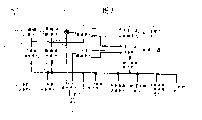
Fig. 1 is the block diagram of formation of the network system of expression execution mode.
Fig. 2 is the block diagram of the formation of expression TV device 1.
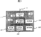
Fig. 3 is the block diagram of the formation of expression VTR2.
Fig. 4 is the block diagram of the formation of expression remote controller 5.
Fig. 5 is the block diagram of the formation of expression printer 3.
Fig. 6 is the block diagram of the formation of the expression generating apparatus that is used to generate the TS signal that sends as broadcast singal.
Fig. 7 is the figure of pattern ground expression from the process of the additional data of demultiplexing TS signal regeneration predetermined channel.
Fig. 8 is the figure that is used to illustrate the data configuration of additional data.
Fig. 9 is the figure that is used for explanation action (action) information.
Figure 10 is the figure that is used to illustrate data (data) information.
Figure 11 is the flow diagram that operational example is handled in expression the 1st.
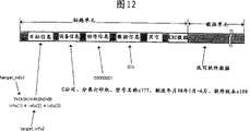
Figure 12 is used for illustrating that the 1st handles the figure of data configuration of the additional data of operational example.
Figure 13 is the flow diagram that operational example is handled in expression the 2nd.
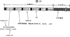
Figure 14 is used for illustrating that the 2nd handles the figure of data configuration of the additional data of operational example.
Embodiment
Below, we illustrate the execution mode of network system of the present invention, electronic equipment, program and broadcasting method with reference to accompanying drawing.
Fig. 1 is the block diagram of all formations of the network system (local bus system) of expression present embodiment.Network system have with network 11 interconnective a plurality of electronic equipment-Fig. 1 in TV device 1, VTR2, printer 3 and DVD player 4.
VTR2 is that video recording, regeneration are with the view data headed by the TV image, the electronic installation of voice data.Again, VTR2 also can write down, read and be used for VTR apparatus operating information data etc.By TV receiving element 1a and these data of network 11 input and output.
DVD player 4 is images, sound of regeneration DVD medium etc., this regenerated signal is outputed to the electronic equipment of TV device 1 by network 11.
Look hearer (user) and can utilize remote controller 5 control TV devices 1 and VTR2 etc.
Network 11 connects TV device 1, VTR2, printer 3 and DVD player 4, can transmitting and receiving data.Use network and equipment in the present embodiment according to the IEEE1394 standard.
Here, we illustrate the network " IEEE1394 high-speed serial bus (hereinafter referred to as IEEE1394I/F) " that uses in the present embodiment.IEEE1394I/F is corresponding with digital chain mode, node branch mode and their combination, the network-bus that can high-freedom degree ground connects.
Again, IEEE1394I/F is the data mode of carrying out serial transmission with the bit rate of 100MHz, 200MHz, 400MHz.Support the next data transmission bauds because have the equipment of upper transmission speed, can mix existence so have the equipment of different transmission speeds.
Again, use IEEE1394I/F, can under the situation that power supply continues to connect, connect or cut-out equipment (so-called warm swap (Hot plug).Again, by the connection of equipment, the on/off of power supply (ON/OFF) etc., bus is all produced replacement, structure again that connects and composes and identification again can distribute ID to connection device.
Again, IEEE1394I/F can discern the bus message that armamentarium connects and composes etc.
Again, in the transmission mode of IEEE1394I/F, asynchronous (Asynchronous) transmission that an existence transmitting grouped data is 1 time and the continuous such 2 kinds of transmission of data synchronization (Isochronous) transmission of transmission in (125 μ s) during each is certain.Asynchronous transmission is for corresponding with the needs of control signal, file data, and non-synchronously the transmission of Chuan Shu data is effective.Again, synchronous transmission is effective for the transmission of the data of the property continuous in time that requires video data and voice signal (so-called data flow data) etc.Therefore, can guarantee transmission band with synchronous transmission.
Again, in IEEE1394I/F, transfer of data all is that unit (quadlet) carries out with 32bit.So, in the situation of the data of being discontented with 32bit, add that " 0 " makes the transmission grouping that 32bit constitutes.
Fig. 2 is a block diagram of representing the formation of TV device 1 in more detail.In addition, this TV device 1 is suitable with electronic equipment of the present invention in the present embodiment.
The TV receiving element 1a of TV device 1 has antenna 101, tuned cell 102, multichannel decomposition (Demultiplex) unit 103, switch element 104, TS decoding unit 105, data buffer unit 106 and TV and receives control unit 107.The demonstration of TV device 1 and control unit 1b have 1394I/F unit 120,1394 sync buffering unit (below, be called the 1394Iso buffer cell) 121,1394 asynchronous grafting buffer cells (below, be called 1394 grafting buffer cells) 122, configuration (configuration) ROM cell 123, connection device information memory cell 124, print control unit 125, rest image buffer cell 126, DVCR decoding unit 127, additional-data storage unit 128, show synthetic control unit 130, display 131, sound synthesizes control unit 132, voice output unit 133, remote control control unit 140 and TV system control unit 150.With internal bus 1101 these formations are coupled together.
Antenna 101 receives the electric wave of digital TV broadcasting from the outside, be transformed into high frequency electrical signal, imports in the tuned cell 102.
Tuned cell 102 has the high frequency TV signal of amplification from antenna 101, select desired, high frequency TV signal by carrier modulation is carried out demodulation, be transformed into the effect of data flow (below, be called TS (Transport Stream (transmitting data stream))) data of numeral.
Multichannel is decomposed (Demux) unit 103 and is selected desired program TS data from the TS signal that is obtained by tuned cell 102, and isolate pay imformation (below, be called CA) data, electronic program guides (below, be called EPG) data and CM described later broadcasting additional data.By switch element 104 with program TS transfer of data to TS decoding unit 105, with other transfer of data to data buffer unit 106.
105 pairs of program TS data from switch element 104 inputs of TS decoding unit are decoded, and the motion video data and the pcm voice data of regeneration numeral output to synthetic control unit 130 of demonstration and the synthetic control unit 132 of sound.
The data of the CA data that data buffer unit 106 storages are come out from program TS data separating, EPG data and CM broadcasting additional data etc.
TV receives control unit 107 to carry out from the control of antenna 101 to TS decoding units 105, switching channels, the control of charging, about the control of EPG data etc.At this moment, and TV system control unit 150 between, the transmission of carrying out the necessary data of remote-control data described later etc. receives.
120 controls of 1394I/F unit, management are by the standardized high-speed serial I/F of IEEE1394, and the transmission of carrying out the data between network 11,1394Iso buffer cell 121,1394 grafting buffer cells 122 etc. receives.
The synchrodata that the 121 temporary transient storages of 1394Iso buffer cell are received by 1394I/F unit 120 is supplied with TS decoding unit 105 by switch element 104.Again, temporary transient storage is supplied with 1394I/F unit 120 by the program TS data that Demux unit 103 and switch element 104 receive.
Grafting register (plug register) that 1394 grafting buffer cells 122 need during by the AV/C asynchronous transmission and segment buffer (segment buffer) constitute, the data that the flow process when temporarily storing about asynchronous transmission is controlled and the place of asynchronous data.The CM broadcasting additional data that will transmit from data buffer unit 106 via it, and various control information data etc. are transferred to the place that needs again.
The equipment intrinsic information of the version information of the software of manufacturer's title of each equipment that connection device information memory cell 124 storage is connected with network 11, device name, serial number, control unit etc. and present whether can energized use these equipment can use the such 2 kinds of equipment link informations of information.
Rest image buffer cell 126 is to accept the control information of digital TV broadcasting additional data, the generation TV device 1 in of CM broadcasting additional data, EPG data etc. in the data buffer unit 106, again by internal bus 1101, various information for still picture by 1394I/F unit 120 input etc. are in order to supply with the buffer storage that shows synthetic control unit 130 and temporarily store.
127 pairs of DVCR decoding units by network 11,1394I/F unit 120,1394Iso buffer cell 121 from digital video code (below, being called DVDR) data accepted decode, regenerate digital motion video data and pcm voice data output to and show synthetic control unit 130, the synthetic control unit 132 of sound.
Additional-data storage unit 128 is to be used for being kept in the additional data that the TV that is stored in data buffer unit 106 receives because equipment can not use the preservation memory of the data that wait and can not implement.It is a flash ROM, even if disconnect the power supply of TV device 1, the content of its storage can not disappear yet.
Show that synthetic control unit 130 switches by the control of system control unit 150 or the Still image data of synthetic animation data and rest image buffer cell 126 from DVCR decoding unit 127, as digital rgb view data and level, vertical synchronizing signal, output to display 131.
The synthetic control unit 132 of sound switch or synthetic from TS decoding unit 105 the pcm voice data and from the pcm voice data of DVCR decoding unit 127, again, control volume, tonequality, presence etc. output to voice output unit 133.
Remote control control unit 140 correspondingly receives the remote-control data that sends from remote controller 5 with the operation that TV looks the hearer, and this transfer of data is arrived TV system control unit 150.
TV system control unit 150 is controlled each unit in the TV device 1 that is connected with internal bus 1101 with being all together.TV system control unit 150 is resolved remote-control data; Control and corresponding each unit of remote-control data; Remote-control data is transferred to TV receives control unit 107; Sent-received message; CM broadcasting additional data in the resolution data buffer cell 106; By sending data with this analysis result and the corresponding network 11 of connection device information; Print processing; Be written to rest image buffer cell 126; Control rest image buffer cell 126 and the synthetic control unit 130 of demonstration; The image of demonstration control TV receiving element 1a, VTR etc. and various information demonstrations etc.Again, the synthetic control unit 132 of TV system control unit 150 control sound carries out the various controls of sound.Again, also control 1394I/F unit 120, management 1394Iso buffer cell 121 is managed 1394 grafting buffer cells 122, therefore, also carries out the transmission reception of data, control VTR2 etc. with the VTR2 that is connected with this network, printer 3 by network 11.
Internal bus 1101 is data/address bus and control bus, as mentioned above, is to be used for images, voice data, to transmit the bus in the TV device 1 of each unit information.
Fig. 3 is a block diagram of representing the formation of VTR2 in more detail.VTR2 has 201,1394 sync buffering unit, 1394I/F unit, 202,1394 asynchronous grafting buffer cells 203, configuration ROM 204, flash ROM 205, VTR control unit 206, VTR unit 207.
1394I/F unit 201 is identical with above-mentioned 1394I/F unit 120, and the transmission of the data in control, supervising the network 11 and the VTR2 receives.
1394 sync buffering unit 202 are identical with 1394 above-mentioned sync buffering unit 121, are that temporary transient storage comes automatic network 11 or from the place of the digital video image data of VTR unit 207.
1394 asynchronous grafting buffer cells 203 are identical with above-mentioned 1394 asynchronous grafting buffer cells 122, as the place of temporary transient storage asynchronous data.
Configuration ROM 204 is identical with above-mentioned configuration ROM 123, wherein stores manufacturer's title, device name, the manufacturing date of VTR2, the equipment intrinsic information of function etc.
Flash ROM 205 is the non-volatile memories that can rewrite.VTR control unit 206 can be rewritten flash ROM 205 by internal bus, and again, miscellaneous equipment also can be rewritten flash ROM 205 by network 11.In this flash ROM 205, storing the program of implementing by VTR control unit 206, the icon data after the conversion etc.
VTR control unit 206 is according to the VTR control information of accepting by network 11,1394I/F unit 201,1394 grafting buffer cells 203, control VTR unit 207.Again, VTR control unit 206 will send to TV device 1 with the video data of corresponding icon of control situation of VTR unit 207 etc. by flash ROM 205,1394 grafting buffer cells 203,1394I/F unit 201, network 11.
VTR unit 207 is made of video band running gear mechanism unit, the control unit of this mechanism and the modem module of vision signal etc., is controlled by VTR control unit 206.
Fig. 4 is a block diagram of representing the formation of remote controller 5 in more detail.Remote controller 5 has key button 501, range cells 502, data transmission receiving element 503, display unit 504, control unit 505.
The user presses key button 501, can indicate and carry out desired operation.
Range cells 502 is the so-called reflection-type range cells that are used for camera etc., sends infrared ray to the range finding object, utilizes its reflection measurement distance.When pressing key button 501, the distance that range cells 502 is measured between TV device 1 and the remote controller 5.
Data send receiving element 503 key code and range data are sent to remote control control unit 140 in the TV device 1.Again, data send receiving element 503 and receive from TV device 1 and reply (responce) etc.
Mistake demonstration when display unit 504 is worked as the key push-botton operation by 1 reception of TV device etc.
The detection of the key button 501 that 505 pairs of control units are pressed, control to the transmission of TV device 1, the reception of replying etc. according to the coding of the key code of the key button 501 of this detection, this key code.The transmission of the range determination of 505 pairs of range cells 502 of control unit and the range data that obtains is controlled again.
Fig. 5 is a block diagram of representing the formation of printer 3 in more detail.Printer 3 has 1394I/F unit 301,1394 asynchronous grafting buffer cells 302, configuration ROM 304, flash ROM 305, printer control unit 306, printer organization unit 307.These key elements are connected with internal bus 1301.
1394I/F unit 301 is identical with above-mentioned 1394I/F unit 120, and the transmission of the data in control, supervising the network 11 and the printer 3 receives.
1394 asynchronous grafting buffer cells 302 are identical with above-mentioned 1394 asynchronous grafting buffer cells 122, as the place of the asynchronous data of temporary transient storaging printing data etc.
Secondly, we illustrate the TS signal of digital TV broadcasting.In Fig. 6, express the generating apparatus that is used to generate the TS signal that sends as broadcasting wave.
Picture signal s1701, voice signal s1702, additional data s1703 are input to the signal generation unit 7 of certain channel.
By video encoder 701, audio coder 702, data encoder 703 these data are encoded respectively, additional header is carried out packetizing, become video PES (PacketizedElementary Stream (through the elementary stream of packetizing)) signal s1704, sound PES signal s1705, data PES signal s1706.
After this, TS packet generator 704 compiles the PES signal s1704~s1706 (demultiplexing) of image, sound, additional data, generates the TS signal s1708 (TS1) of a channel.
Channel 751,752 for other also is same, compiles image, sound, additional data (demultiplexing), generates TS signal s1709 (TS2), s1710 (TS3).Channel number both can be 1, further also can be a plurality of.
Compile 3 TS signal s1708, s1709, s1710 (demultiplexing) by TS demultiplexing device 753 once more, generate TS signal (TS4) s1711.
Again, in the TS signal, when carrying out packetizing, demultiplexing, the identifier during as regeneration, the additional title that comprises PID (Program ID (program ID)), PMT (Program MapTable (program ground chart)), table_ID, tag_value etc.
In addition, about above-mentioned compiling method, packetizing method, demultiplexing method, usually by IEC13818-1, IEC13818-2, IEC13818-3 regulation, but we omit their details.
Become 1 TS signal s1711 (TS4), after modulating, send from antenna 755 by modulator 754.
In Fig. 7, express to pattern from TS signal s1711 (TS4) process of the additional data s1703 of regeneration (extraction) TS signal s1708 (TS1).From the TS4 of demultiplexing, at first only separate TS1.Because wherein comprised video (video) unit, audio frequency (audio) unit, such 3 unit, data (data) unit, so therefrom only collect data cell, the deletion header cell generates original data (additional data).In these separation, collecting, use the identifier of the title of PID, PMT, table ID, tag_value etc.
Fig. 8 represents the data configuration of additional data.Additional data is divided into title (Header) unit and data (Data) unit, and TV system control unit 150 is resolved the content of header cell, carries out the processing of data cell.
In Fig. 8, express the example that header cell constitutes.Header cell comprises target (target) information, action (action) information, data (data) information, CRC data.
Target information comprises the information of the electronic equipment (target device) that is used for the specific object that becomes aftermentioned action.Target information is if the information of particular target device then also can be any information.For example, also can be the information that can compare with the equipment intrinsic information (version of manufacturer's title, device name, serial number, manufacturing date, software etc.) that is stored in the above-mentioned configuration ROM.
Action message as shown in Figure 9, is the part that is defined as the processing (operation) that target device is carried out.For example, be the action of the rewriting of data, the propaganda of using the CM data, demonstration, printing etc.
Data message as shown in figure 10, comprises expression and is stored in data class in the data cell-for example, routine data or print data-application message.
(the 1st operational example)
Secondly, we illustrate the processing operational example in the network system shown in Figure 1 with reference to the flow diagram of Figure 11.In this example, TV device 1 (goods of A company), VTR2 (goods of B company), printer (goods of C company, device name c777, are made in March, 98 on days, software version c100.In addition, the Control Software of printer 3 is stored in the flash ROM 305) be connected with network 11.
Again, broadcast singal in this example, as illustrated in fig. 6, be the TS4 (TS signal s1711) that forms behind demultiplexing TS1 (TS signal s1708), TS2 (TS signal s1709), such 3 the TS signals of TS3 (TS signal s1710), wherein in TS1, comprise the CM broadcasting of C company, in this CM broadcasting, exist additional data.
Specifically, in the CM of C company broadcast data, comprising the printer of C corporate system that will have device name c777, make in January, 98~June on days and software version c100 as object, be rewritten into the additional data of redaction c101 for Control Software this version c100.Figure 12 represents the data configuration of this additional data.As shown in figure 12, in each information of header cell, store the value of representing additional data content, in data cell, storing rewriting software data (redaction data c101).
Again, the power supply of VTR2 and printer 3 is connected, and is in operable state.They were to use with TV device 1 with being connected in the past, were discerned by TV device 1.
Again, the power supply of TV device 1 and DVD player 4 is in off-state.But DVD player 4 was used (being in on-state) with TV device 1 in the past with being connected, was discerned by TV device 1.Here, bus reset takes place in (st601.01) when the mains switch of TV device 1 is connected, and makes the IEEE1394I/F initialization, constructs link information again, discerns connection device again.So, discern by 1394I/F unit 120 respectively by operable VTR1 of energized and printer 3, discern (st601.02) by TV system control unit 150.
Secondly, TV system control unit 150 control 1394 grafting buffer cells 122 and 1394I/F unit 120, between the VTR2 and printer 3 that are connected with network 11, in order to make TV device 1 become consumer (consumer), CTR2 becomes producer (producer) and forms asynchronous connection the (asynchronous connection) (st601.03) with printer 3.
And the requirement (st601.04) that TV system control unit 150 sends the transmission equipment intrinsic information to each equipment when receiving this information, is stored in (st601.05) in the connection device information memory cell 124.Again, TV system control unit 150 is stored in the connection device information memory cell 124 by the equipment intrinsic information of internal bus 1101 with TV device 1 self.
At this moment, if the identical value of equipment intrinsic information that the new equipment intrinsic information that receives received when having with bus reset in the past, then TV system control unit 150 intactly keeps value in the past, if difference is then rewritten this part.Again, when bus reset, in the situation of the equipment that before can not discerning, receives, 150 of TV system control units make can use information the becoming and cannot use of intrinsic information of this equipment, intactly keep part in addition, in this example, the facility information of VTR2 and printer 3 is with original the same, and making in the facility information about DVD player 4 use information to become and cannot use.
Aspect of above-mentioned processing operation (st601.02), behind the power connection, TV device 1 by antenna 101, as illustrated in fig. 6, receives the broadcast singal (electric wave) that sends over.The broadcast singal that receives in tuned cell 102, carries out tuning, amplification, demodulation, become as shown in Figure 7 will be (st601.11) by the TS signal (TS4) of demultiplexing.
Here, in the broadcasting of TS signal (TS1), the CM of beginning C company.At this moment, TS1 as Fig. 7 explanation, is at first isolated in Demux unit 103, secondly this TS1 is separated into video unit, audio unit, data cell (additional data) (st601.12, st601.13).In addition, when not having additional data, with unprocessed end (st601.12, st601.51).
After this, the data of video unit and the data of audio unit are sent to TS decoding unit 105, decode by switch element 104.
On the other hand, will send to data buffer unit 106 through the additional data that separates.When additional data being input in the data buffer unit 106,150 pairs of these data of TV system control unit are decoded, and resolve header cell (st601.14).Whether TV system control unit 150 is differentiated this additional data according to the matching of data in the header cell is the respective action (st601.15) of connection device.In addition, when not being the respective action of connection device, for example, when being the CA data as the EPG data, perhaps, in the time of can not resolving, move to other processing (st601.52) corresponding with it.
When being the respective action of connection device, further resolve header cell inside, differentiate this additional data and be the data as object with the device name c777 in the goods of C company, serial number c123, software version c100, whether retrieval exists the equipment intrinsic information (st601.16) consistent with this information in connection device information memory cell 124.In addition, when not existing, as unprocessed, discarded this additional data finishes (st601.53).
When existing consistent equipment intrinsic information in the connection device information memory cell 124, can use information with reference to this, whether investigation can use this equipment (st601.17).In the time cannot using, this additional data is kept in the additional-data storage unit 128, on display 131, demonstrate this information.For example, as " receiving the information of the printer c777 of the C company that uses about you.Power supply that please enable printer.”。
In addition, when the additional data of preserving becomes equipment and can use, implement its content (st601.54).Again, by the additional data of TV system control unit 150 management preservations, even if, discard the additional data of (deletion) this preservation through in the situation of also not implementing more than or equal to certain certain hour.
In this example, be printer 3 (goods of C company, device name c777, make in March, 98 on days, software version c100), because power connection can use, so advance forward, from the action message of the header cell of additional data, differentiating motion action is to rewrite software (st601.18).In addition, when not being such, carry out other processing (st601.55) according to the action message of header cell.
Secondly, TV system control unit 150 is because it is relevant with the rewriting processing of software data to differentiate this additional data, so in order to make TV device 1 become the producer, printer 3 becomes the consumer and forms asynchronous connection (st601.19).
And, TV system control unit 150, by network 11, the data that will give in the data cell of additional data write in the segment buffer in the 1394 grafting buffer cells 302 of printer 3 (st601.20).
When DTD, TV system control unit 150 cut off with printer 3 between asynchronous connection of forming, end (st601.21).
On the other hand, the data that receive in the segment buffer in the printer control unit 306 parsings 1394 grafting buffer cells 302 of printer 3, differentiation is the redaction data of Control Software of the printer of oneself, with the program unit (st601.22) of this transfer of data in the flash ROM 305.
As mentioned above,, then utilize the additional data that is included in the broadcasting number signal, automatically make the edition upgrading of the Control Software of the printer 3 that is connected with local area network (LAN) 11 if according to this operational example.
(the 2nd operational example)
Secondly, we illustrate the processing operational example in the network system shown in Figure 1 with reference to the flow diagram of Figure 13.In this example, TV device 1 (goods of A company), VTR2 (goods of B company, classification VHS video (Video), device name b123, make in July, 92 on days) are connected with network 11 with printer 3 (goods of C company).
Again, the broadcast singal in this example, identical with aforesaid operations example 1, in TS1 (TS signal s1708), comprise CM broadcasting, in this CM broadcasting, exist additional data.
Specifically, in the CM of S company broadcast data, comprising the VHS video of will classifying, make before in January, 93 on days or the similar product of the goods s123 of S company as object, change the ad data of the propaganda activity of buying S company new product, if printer is then set for printing.In Figure 14, express the data configuration of this additional data.As shown in figure 14, the value of representing additional data content is stored in the header cell, print data is stored in the data cell.
When the mains switch of TV device 1 is connected (st602.01), identical with aforesaid operations example 1, bus reset takes place, make the IEEE1394I/F initialization, construct link information again, the electronic equipment (st602.02) that 150 identifications of TV system control unit are connected with network 11.
Secondly, TV system control unit 150 control 1394 grafting buffer cells 122 and 1394I/F unit 120, between the VTR2 and printer 3 that are connected with network 11, become the consumer in order to make TV device 1, CTR2 becomes the producer and forms asynchronous connection the (st602.03) with printer 3.
And the requirement (st602.04) that TV system control unit 150 sends the transmission equipment intrinsic information to each equipment when receiving this information, is stored in (st602.05) in the connection device information memory cell 124.If VTR2 is described, then in B company goods, storage is called classification VHS video, device name b123, makes the information in July, 92 on days.Be stored in the device information storage unit 124 by the equipment intrinsic information of internal bus 1101 TV device 1 self again.
Aspect of above-mentioned processing operation (st602.02), behind the power connection, TV device 1 by antenna 101, as illustrated in fig. 6, receives the broadcast singal that sends over.The broadcast singal that receives in tuned cell 102, carries out tuning, amplification, demodulation, become as shown in Figure 7 will be (st602.11) by the TS signal (TS4) of demultiplexing.
Here, in the broadcasting of TS signal (TS1), the CM of beginning S company.At this moment, TS1 as Fig. 7 explanation, is at first isolated in Demux unit 103, secondly this TS1 is separated into video unit, audio unit, data cell (additional data) (st602.12, st602.13).In addition, when not having additional data, do not handle and finish (st602.12, st602.51).
After this, the data of video unit and the data of audio unit are sent to TS decoding unit 105, decode by switch element 104.
On the other hand, will send to data buffer unit 106 through the additional data that separates.When additional data being input in the data buffer unit 106,150 pairs of these data of TV system control unit are decoded, and resolve header cell (st602.14).Whether TV system control unit 150 is differentiated this additional data according to the matching of data in the header cell is the respective action (st602.15) of connection device.In addition, when not being the respective action of connection device, for example, when being the CA data as the EPG data, perhaps, in the time of can not resolving, move to other processing (st602.52) corresponding with it.
When being the respective action of connection device, further resolve header cell inside, differentiating this additional data is that in January, 93 on days is retrieved whether there be the equipment intrinsic information (st602.16) consistent with this information in connection device information memory cell 124 in the past as the data of object in classification VHS video, manufacturing.In addition, when not existing, as not handling, discarded this additional data finishes (st602.53).
In this example, because VTR2 becomes object (in connection device information memory cell 124, having consistent equipment intrinsic information) (st602.17), so advance forward, from the action message of the header cell of additional data, differentiating motion action is print data (st602.18).In addition, when not being such, carry out other processing (st602.55) according to the action message of header cell.
Secondly, TV system control unit 150 is because it is relevant with print processing to differentiate this additional data, so whether retrieval exists printer (st602.19) on network.In this example, on network, there is printer.Therefore, TV system control unit 150 is printed in order to implement, and becomes the producer in order to make TV device 1, and printer 3 becomes the consumer and forms asynchronous connection (st602.20).
And TV system control unit 150 uses print control unit 125, by the IEEE1394 network, gives printer 3 with the transfer of data in the data buffer unit 106.These data are write in the segment buffer in the 1394 grafting buffer cells 302 of printer 3 (st602.21).
When DTD, TV system control unit 150 be breaking at printer 3 between asynchronous connection of forming, finish (st602.22).
On the other hand, the data that receive in the segment buffer in the printer control unit 306 parsings 1394 grafting buffer cells 302 of printer 3, differentiation is the print data of the printer of oneself, and this transfer of data to printer organization unit 307, is implemented to print (st602.23).
As mentioned above, if according to this operational example, then can be corresponding with the result of the equipment intrinsic information that compares additional data and VTR2, in printer 3, implement print processing as other equipment.
In addition, in the above-described embodiment, use IEEE1394 as the network that is used to connect each equipment, but also can use 12C bus, Ethernet (R), USB etc., the identification component of connection device is set.Network both can be wired also can be wireless.The electric transmission medium are not limited to the signal of telecommunication, also can be fiber optic cables, infrared ray, electric wave etc.Also can not a kind, but a plurality of network coupled are got up again.
That is, preferably network is a plurality of electron device part that can interconnect the housing that has separately.
Again, in the above-described embodiment, connect by the mains switch that makes the TV device, in IEEE1394I/F, add bus reset, the identification connection device, if but can carry out the on/off of the power supply of miscellaneous equipment, the insertion of connector is extracted etc., add bus reset in IEEE1394I/F, then it can be any operation.
Again, in the present embodiment, we have illustrated connection TV device 1, VTR2, printer 3, the network system of DVD player 4, but the present invention can be applied to other electronic equipment, for example, TV tuner, the FM tuner, the audio cassette recorder, the AC equipment of amplifier etc., PC (personal computer), scanner, FAX, phone, modulator, display monitor, printer, the OA of photocopier etc. (office application) equipment, refrigerator, washing machine, the tame electrical article of flatiron etc., the gate inhibition, the bathroom management system, the in-home network system of crime prevention system etc.
Again, the TV device 1 in the present embodiment has many functions of tuned cell, Demux unit, TV system control unit etc., but these functions also may reside in the equipment that connects by IEEE1394I/F, for example in the printer, control with being all together.
Again, in the present embodiment, we have represented rewrite data (software release upgrade) processing and print processing, as an example of " predetermined process " implemented in electronic equipment.But, as mentioned above, because the present invention can be applied to all electronic equipments, thus corresponding with kind and function as the electronic equipment of object, can implement various processing.For example, as " predetermined process ", also can implement to the demonstration of TV device and PC handle (impel edition upgrading demonstration, inform that the demonstration of carrying out the edition upgrading operation, the electronic equipment that expression is connected become the demonstration of audience etc.) with to the voice output processing of AV equipment.Again, because TV device 1 also is a kind of electronic equipment, so TV device 1 also can be implemented predetermined processing according to additional data in TV device 1 self.
In addition, in the present embodiment, treatment circuit according to additional data control electronic equipment is set in the enclosure interior of TV device 1.But, the parts and the above-mentioned treatment circuit of receiving broadcast signal also can not need be set in same housing, as other housing, treatment circuit is arranged on the inside of the electronic equipment beyond independent device or the TV device 1.
(other execution mode)
For the various device that makes the function that will realize above-mentioned execution mode is operated, to device that is connected with this various device or intrasystem computer, supply is used to realize the procedure code of software of the function of above-mentioned execution mode, is implemented to be also contained in the category of the present invention by according to the program in the computer that is stored in this system or device (VPU or MPU) above-mentioned various device being operated.
Again, at this moment, the procedure code of above-mentioned software self is realized the function of above-mentioned execution mode, and this procedure code self constitutes the present invention.As the transmission medium of this procedure code, can be used in the communication medium (Wireline of optical fiber etc. and radiolink etc.) of computer network (WAN of LAN, internet etc., the cordless communication network etc.) system that is used for program information transmitted as carrier wave and supplies with.
Further, be used for the said procedure sign indicating number is supplied with the parts of computer, the medium of for example storing certain procedure code constitutes the present invention.As the medium of certain procedure code of storage, for example, the enough floppy disks of energy, hard disk, CD, photomagneto disk, CD-ROM, tape, Nonvolatile memory card, ROM etc.
Again, procedure code by computer-implemented supply, not only can realize the function of above-mentioned execution mode, and jointly realize in the situation of function of above-mentioned execution mode with the OS (operating system) that in computer, makes the operation of this procedure code or other application software etc., also certain procedure code can be comprised in embodiments of the present invention, this is self-evident.
Further, expansion board that the procedure code that will supply with is stored in computer with functional expansion unit that computer is connected in the memory that has after, indication according to this procedure code, the CPU that has in this expansion board and the functional expansion unit etc. carries out part or all of actual treatment, the situation that realizes the function of above-mentioned execution mode by this processing is also contained among the present invention, and this is self-evident.
Again, the shape of Biao Shi each unit and structure in the above-described embodiment, whichever only are in order to implement an example of specific model of the present invention, can not to limit ground according to their and explain technical scope of the present invention, and this is self-evident.That is, only otherwise break away from spirit of the present invention or its principal character, just can be with various form enforcement the present invention.
Claims (10)
1. network system comprises:
The a plurality of electronic equipments that are connected with network, above-mentioned a plurality of electronic equipment comprises the receiving equipment that at least one can receiving broadcast signal, above-mentioned broadcast singal comprises the data that are used for recognition objective equipment and is used to control the data of described target device, and wherein said target device is the electronic equipment that is connected with above-mentioned network except that above-mentioned receiving equipment; With
Treatment circuit, this treatment circuit relatively is included in being used in the above-mentioned broadcast singal and discerns the data of above-mentioned target device and the intrinsic information of above-mentioned target device, according to this comparative result, according to the data that are used to control above-mentioned target device, produce the signal that makes above-mentioned target device carry out predetermined process.
2. the described network system of claim 1 is characterized in that:
Above-mentioned treatment circuit is configured in the housing of above-mentioned receiving equipment.
3. the described network system of claim 1 is characterized in that:
Above-mentioned each electronic equipment has housing separately.
4. the described network system of claim 1 is characterized in that:
Specify above-mentioned predetermined process by the above-mentioned data that are included in the above-mentioned broadcast singal.
5. network system comprises:
The a plurality of electronic equipments that are connected with network, above-mentioned a plurality of electronic equipment comprises the receiving equipment that at least one can receiving broadcast signal, above-mentioned broadcast singal comprises the data that are used to discern the data of a plurality of target devices and are used to control described target device, and wherein said a plurality of target devices are the electronic equipments that are connected with above-mentioned network except that above-mentioned receiving equipment; With
Treatment circuit, this treatment circuit relatively is included in being used in the above-mentioned broadcast singal and discerns the data of first target device and the intrinsic information of above-mentioned first target device, according to this comparative result, according to the data that are used to control second target device that is connected with above-mentioned first target device via above-mentioned network, produce the signal that makes above-mentioned second target device carry out predetermined process.
6. the described network system of claim 1 is characterized in that:
Above-mentioned predetermined process is that the edition upgrading of the software possessed of above-mentioned electronic equipment is handled.
7. the described network system of claim 1 is characterized in that:
Above-mentioned predetermined process is a print processing.
8. the described network system of claim 1 is characterized in that:
Above-mentioned predetermined process is to show to handle.
9. receiving equipment that can be connected with the network that has been connected electronic equipment comprises:
Receiving element, receiving broadcast signal; With
Treatment circuit relatively is included in being used in the above-mentioned broadcast singal to discern the data of above-mentioned electronic equipment and the intrinsic information of above-mentioned electronic equipment, and according to this comparative result, produces to be used to make above-mentioned electronic equipment to carry out the signal of predetermined process.
10. sending method that sends broadcast singal comprises:
The step of received image signal, voice signal and additional data;
The step that above-mentioned picture signal, tut signal and above-mentioned additional data are encoded respectively;
To above-mentioned picture signal, tut signal and the above-mentioned additional data step of carrying out packetize respectively behind the coding;
Above-mentioned picture signal after the packetize, tut signal and above-mentioned additional data are carried out the step of multipleization respectively; With
Modulate the signal after multipleization, and with its step that sends as broadcast singal,
Wherein, above-mentioned additional data comprises the relevant data of target device that receive the receiving equipment electronic equipment in addition of this broadcast singal with conduct,
Above-mentioned data comprise the data that compare with the intrinsic information of above-mentioned target device for recognition objective equipment and represent to make according to the comparative result of these data and above-mentioned intrinsic information data predetermined process, that be used to control above-mentioned target device of above-mentioned target device execution.
Applications Claiming Priority (4)
| Application Number | Priority Date | Filing Date | Title |
|---|---|---|---|
| JP2003151174 | 2003-05-28 | ||
| JP151174/2003 | 2003-05-28 | ||
| JP131410/2004 | 2004-04-27 | ||
| JP2004131410A JP4693363B2 (en) | 2003-05-28 | 2004-04-27 | Television apparatus and control method thereof |
Publications (2)
| Publication Number | Publication Date |
|---|---|
| CN1574743A CN1574743A (en) | 2005-02-02 |
| CN100355236C true CN100355236C (en) | 2007-12-12 |
Family
ID=33455560
Family Applications (1)
| Application Number | Title | Priority Date | Filing Date |
|---|---|---|---|
| CNB2004100432552A Expired - Fee Related CN100355236C (en) | 2003-05-28 | 2004-05-14 | Network system and electronic device |
Country Status (4)
| Country | Link |
|---|---|
| US (1) | US7610609B2 (en) |
| JP (1) | JP4693363B2 (en) |
| KR (1) | KR20040103340A (en) |
| CN (1) | CN100355236C (en) |
Families Citing this family (8)
| Publication number | Priority date | Publication date | Assignee | Title |
|---|---|---|---|---|
| KR100736032B1 (en) * | 2005-02-02 | 2007-07-06 | 삼성전자주식회사 | Mobile storage, video equipment and channel limiting method for video equipment using mobile storage |
| EP1715603A3 (en) | 2005-04-18 | 2009-11-25 | LG Electronics, Inc. | Apparatus and method for controlling electric appliances using broadcast wave, and apparatus and method for controlling home network |
| JP2007050566A (en) | 2005-08-16 | 2007-03-01 | Canon Inc | Image forming apparatus and its control method |
| KR100781523B1 (en) * | 2006-04-25 | 2007-12-03 | 삼성전자주식회사 | Apparatus and method for structuring IP identification packet and allotting IP |
| KR100791304B1 (en) * | 2006-07-24 | 2008-01-04 | 삼성전자주식회사 | Apparatus, system and method for software upgrading |
| JP4775400B2 (en) * | 2008-04-15 | 2011-09-21 | 船井電機株式会社 | Audiovisual system |
| US20120072896A1 (en) * | 2009-06-05 | 2012-03-22 | Haruhito Watanabe | Software updating system, electronic devices, and software updating method |
| CN102663885B (en) * | 2012-03-23 | 2017-11-07 | 中兴通讯股份有限公司 | A kind of method operated to display device, system and relevant device |
Citations (4)
| Publication number | Priority date | Publication date | Assignee | Title |
|---|---|---|---|---|
| TW304251B (en) * | 1996-10-04 | 1997-05-01 | Cheng Shen Co Ltd | Consumer electric apparatus control system |
| EP0783229A1 (en) * | 1995-12-28 | 1997-07-09 | U.S. Narrow Networks, Inc. | Method and apparatus for providing coupons and information printouts to a consumer |
| EP0895157A1 (en) * | 1997-07-31 | 1999-02-03 | Matsushita Electric Industrial Co., Ltd. | Remote maintenance method and apparatus |
| EP1021021A2 (en) * | 1999-01-13 | 2000-07-19 | International Business Machines Corporation | Method and apparatus for providing awareness-triggered push |
Family Cites Families (22)
| Publication number | Priority date | Publication date | Assignee | Title |
|---|---|---|---|---|
| US4633309A (en) * | 1985-05-06 | 1986-12-30 | Oak Industries Inc. | Cable television master/slave decoder control |
| US4695880A (en) * | 1985-07-30 | 1987-09-22 | Postron Corp. | Electronic information dissemination system |
| US5886732A (en) * | 1995-11-22 | 1999-03-23 | Samsung Information Systems America | Set-top electronics and network interface unit arrangement |
| JP3870983B2 (en) | 1997-02-17 | 2007-01-24 | ソニー株式会社 | Electronic device control apparatus and method, and electronic device |
| JP3896625B2 (en) * | 1997-03-07 | 2007-03-22 | ソニー株式会社 | Data transmitting apparatus, data receiving apparatus, data transmitting method and data receiving method |
| JPH1124899A (en) * | 1997-07-04 | 1999-01-29 | Sony Corp | Electronic instrument and electronic instrument system |
| JP3261399B2 (en) | 1997-07-31 | 2002-02-25 | 松下電器産業株式会社 | Remote maintenance method and remote maintenance device |
| JP3684818B2 (en) * | 1998-02-23 | 2005-08-17 | セイコーエプソン株式会社 | Television broadcast multiplexed data printing method and system, and recording medium recording a television broadcast multiplexed data processing program |
| KR100385966B1 (en) | 1998-05-06 | 2003-08-19 | 삼성전자주식회사 | Method and apparatus for granting the right of control command for digital device in home network |
| US6038425A (en) * | 1998-08-03 | 2000-03-14 | Jeffrey; Ross A. | Audio/video signal redistribution system |
| US6282713B1 (en) * | 1998-12-21 | 2001-08-28 | Sony Corporation | Method and apparatus for providing on-demand electronic advertising |
| US6588017B1 (en) * | 1999-01-27 | 2003-07-01 | Diva Systems Corporation | Master and slave subscriber stations for digital video and interactive services |
| JP2001134581A (en) * | 1999-11-02 | 2001-05-18 | Nec Corp | Method, device, and receiver for advertisement, and recording medium |
| JP4265053B2 (en) * | 1999-11-04 | 2009-05-20 | ソニー株式会社 | Digital broadcast receiving system, digital broadcast receiving apparatus, receiving apparatus, printing apparatus, and printing method |
| JP2002152650A (en) * | 2000-11-10 | 2002-05-24 | Sharp Corp | Digital broadcast receiving system |
| JP2002196943A (en) * | 2000-12-27 | 2002-07-12 | Victor Co Of Japan Ltd | Digital broadcasting down load system |
| JP2002290853A (en) * | 2001-03-22 | 2002-10-04 | Canon Inc | Receiver, method, and program for television broadcast reception |
| KR100403300B1 (en) | 2001-07-26 | 2003-10-23 | 전자부품연구원 | Equipment for extracting the control signal of entertainment equipment in digital broadcasting signal and extracting method therein |
| JP2003046986A (en) | 2001-08-03 | 2003-02-14 | Matsushita Electric Ind Co Ltd | Receiver |
| JP3863118B2 (en) * | 2002-04-01 | 2006-12-27 | 松下電器産業株式会社 | Receiving device, printing device, and firmware update system |
| JP4401721B2 (en) * | 2002-09-26 | 2010-01-20 | キヤノン株式会社 | Video receiver |
| JP2004173128A (en) * | 2002-11-22 | 2004-06-17 | Clarion Co Ltd | Digital broadcasting system, digital broadcasting receiver and digital broadcasting terminal device |
-
2004
- 2004-04-27 JP JP2004131410A patent/JP4693363B2/en not_active Expired - Fee Related
- 2004-05-14 US US10/845,176 patent/US7610609B2/en not_active Expired - Fee Related
- 2004-05-14 CN CNB2004100432552A patent/CN100355236C/en not_active Expired - Fee Related
- 2004-05-27 KR KR1020040037752A patent/KR20040103340A/en active Search and Examination
Patent Citations (4)
| Publication number | Priority date | Publication date | Assignee | Title |
|---|---|---|---|---|
| EP0783229A1 (en) * | 1995-12-28 | 1997-07-09 | U.S. Narrow Networks, Inc. | Method and apparatus for providing coupons and information printouts to a consumer |
| TW304251B (en) * | 1996-10-04 | 1997-05-01 | Cheng Shen Co Ltd | Consumer electric apparatus control system |
| EP0895157A1 (en) * | 1997-07-31 | 1999-02-03 | Matsushita Electric Industrial Co., Ltd. | Remote maintenance method and apparatus |
| EP1021021A2 (en) * | 1999-01-13 | 2000-07-19 | International Business Machines Corporation | Method and apparatus for providing awareness-triggered push |
Also Published As
| Publication number | Publication date |
|---|---|
| JP4693363B2 (en) | 2011-06-01 |
| KR20040103340A (en) | 2004-12-08 |
| US7610609B2 (en) | 2009-10-27 |
| JP2005012766A (en) | 2005-01-13 |
| US20040240475A1 (en) | 2004-12-02 |
| CN1574743A (en) | 2005-02-02 |
Similar Documents
| Publication | Publication Date | Title |
|---|---|---|
| EP0873009B1 (en) | Multimedia system for transferring and receiving program number and methods therefor | |
| KR100703099B1 (en) | Terminal apparatus, center apparatus, communication system, terminal apparatus control method, center apparatus control method, computer readable recording media in which terminal apparatus control program have been recorded, and computer readable recording media in which center apparatus control program have been recorded | |
| KR100339436B1 (en) | Portable viewing system | |
| RU2345401C2 (en) | Universal two-way consecutive interface of data transmission and data transmission method | |
| JP3353370B2 (en) | Remote control device for recording / reproducing device and remote control method | |
| CN100357950C (en) | Content viewing support apparatus and content viewing support method, and computer program | |
| JPH11225292A (en) | Digital broadcast receiver and reception method | |
| WO2002019691A3 (en) | Electronic program guide subsystem for receiving and processing electronic program guide information from a set-top box | |
| KR20000004855A (en) | Information transmission apparatus and method | |
| EP1039758B1 (en) | Apparatus for creating shared video scene content | |
| US6754347B1 (en) | Input/output unit, input/output method, and receiving unit | |
| CN100355236C (en) | Network system and electronic device | |
| US20140233922A1 (en) | Method and apparatus for storing broadcast program | |
| JP2000184303A (en) | Receiving system and device for digital broadcast | |
| CN102111588A (en) | Broadcasting receiving device and broadcasting receiving method | |
| KR100445006B1 (en) | Method and apparatus for managing a recording broadcasting program list | |
| JP2003198999A (en) | Broadcast receiving device with video-recorder control function | |
| CN100574366C (en) | Channel-changing method in the digital cable set-top box | |
| JP4366742B2 (en) | Receiver | |
| JP2001275080A (en) | Digital broadcast video-recording device | |
| CN101536516A (en) | Broadcast-program recording-programming system and broadcast-program recording-programming method | |
| JP2000032415A (en) | Receiver | |
| EP1098315A1 (en) | Electronic device, method of signal processing, method of input signal switching, and download system | |
| JP2003143561A (en) | Recorder | |
| JP2000010906A (en) | Audiovisual equipment and its control method |
Legal Events
| Date | Code | Title | Description |
|---|---|---|---|
| C06 | Publication | ||
| PB01 | Publication | ||
| C10 | Entry into substantive examination | ||
| SE01 | Entry into force of request for substantive examination | ||
| C14 | Grant of patent or utility model | ||
| GR01 | Patent grant | ||
| CF01 | Termination of patent right due to non-payment of annual fee |
Granted publication date: 20071212 Termination date: 20170514 |
|
| CF01 | Termination of patent right due to non-payment of annual fee |