JP3870983B2 - Electronic device control apparatus and method, and electronic device - Google Patents
Electronic device control apparatus and method, and electronic device Download PDFInfo
- Publication number
- JP3870983B2 JP3870983B2 JP03157797A JP3157797A JP3870983B2 JP 3870983 B2 JP3870983 B2 JP 3870983B2 JP 03157797 A JP03157797 A JP 03157797A JP 3157797 A JP3157797 A JP 3157797A JP 3870983 B2 JP3870983 B2 JP 3870983B2
- Authority
- JP
- Japan
- Prior art keywords
- electronic device
- user interface
- interface information
- control
- transmission
- Prior art date
- Legal status (The legal status is an assumption and is not a legal conclusion. Google has not performed a legal analysis and makes no representation as to the accuracy of the status listed.)
- Expired - Lifetime
Links
- 238000000034 method Methods 0.000 title claims description 30
- 230000005540 biological transmission Effects 0.000 claims description 44
- 238000004891 communication Methods 0.000 claims description 24
- 238000012545 processing Methods 0.000 claims description 11
- 230000006870 function Effects 0.000 description 24
- 238000010586 diagram Methods 0.000 description 13
- 230000002093 peripheral effect Effects 0.000 description 13
- 101000969688 Homo sapiens Macrophage-expressed gene 1 protein Proteins 0.000 description 8
- 102100021285 Macrophage-expressed gene 1 protein Human genes 0.000 description 8
- 238000009434 installation Methods 0.000 description 6
- 230000005236 sound signal Effects 0.000 description 5
- 238000012546 transfer Methods 0.000 description 5
- 230000004044 response Effects 0.000 description 4
- 101100082129 Homo sapiens PALS2 gene Proteins 0.000 description 1
- 102100034053 Protein PALS2 Human genes 0.000 description 1
- 101100296979 Saccharomyces cerevisiae (strain ATCC 204508 / S288c) PEP5 gene Proteins 0.000 description 1
- 101100484930 Saccharomyces cerevisiae (strain ATCC 204508 / S288c) VPS41 gene Proteins 0.000 description 1
- 238000013461 design Methods 0.000 description 1
- 230000000694 effects Effects 0.000 description 1
- 238000011900 installation process Methods 0.000 description 1
- 238000012544 monitoring process Methods 0.000 description 1
- 230000000007 visual effect Effects 0.000 description 1
Images


Classifications
-
- G—PHYSICS
- G06—COMPUTING; CALCULATING OR COUNTING
- G06F—ELECTRIC DIGITAL DATA PROCESSING
- G06F9/00—Arrangements for program control, e.g. control units
-
- H—ELECTRICITY
- H04—ELECTRIC COMMUNICATION TECHNIQUE
- H04L—TRANSMISSION OF DIGITAL INFORMATION, e.g. TELEGRAPHIC COMMUNICATION
- H04L12/00—Data switching networks
- H04L12/28—Data switching networks characterised by path configuration, e.g. LAN [Local Area Networks] or WAN [Wide Area Networks]
- H04L12/40—Bus networks
- H04L12/40052—High-speed IEEE 1394 serial bus
- H04L12/40117—Interconnection of audio or video/imaging devices
-
- G—PHYSICS
- G06—COMPUTING; CALCULATING OR COUNTING
- G06F—ELECTRIC DIGITAL DATA PROCESSING
- G06F15/00—Digital computers in general; Data processing equipment in general
- G06F15/16—Combinations of two or more digital computers each having at least an arithmetic unit, a program unit and a register, e.g. for a simultaneous processing of several programs
- G06F15/177—Initialisation or configuration control
-
- G—PHYSICS
- G06—COMPUTING; CALCULATING OR COUNTING
- G06F—ELECTRIC DIGITAL DATA PROCESSING
- G06F9/00—Arrangements for program control, e.g. control units
- G06F9/06—Arrangements for program control, e.g. control units using stored programs, i.e. using an internal store of processing equipment to receive or retain programs
- G06F9/44—Arrangements for executing specific programs
- G06F9/4401—Bootstrapping
- G06F9/4411—Configuring for operating with peripheral devices; Loading of device drivers
-
- G—PHYSICS
- G11—INFORMATION STORAGE
- G11B—INFORMATION STORAGE BASED ON RELATIVE MOVEMENT BETWEEN RECORD CARRIER AND TRANSDUCER
- G11B27/00—Editing; Indexing; Addressing; Timing or synchronising; Monitoring; Measuring tape travel
- G11B27/002—Programmed access in sequence to a plurality of record carriers or indexed parts, e.g. tracks, thereof, e.g. for editing
-
- G—PHYSICS
- G11—INFORMATION STORAGE
- G11B—INFORMATION STORAGE BASED ON RELATIVE MOVEMENT BETWEEN RECORD CARRIER AND TRANSDUCER
- G11B27/00—Editing; Indexing; Addressing; Timing or synchronising; Monitoring; Measuring tape travel
- G11B27/02—Editing, e.g. varying the order of information signals recorded on, or reproduced from, record carriers
- G11B27/022—Electronic editing of analogue information signals, e.g. audio or video signals
- G11B27/028—Electronic editing of analogue information signals, e.g. audio or video signals with computer assistance
-
- G—PHYSICS
- G11—INFORMATION STORAGE
- G11B—INFORMATION STORAGE BASED ON RELATIVE MOVEMENT BETWEEN RECORD CARRIER AND TRANSDUCER
- G11B27/00—Editing; Indexing; Addressing; Timing or synchronising; Monitoring; Measuring tape travel
- G11B27/02—Editing, e.g. varying the order of information signals recorded on, or reproduced from, record carriers
- G11B27/031—Electronic editing of digitised analogue information signals, e.g. audio or video signals
-
- G—PHYSICS
- G11—INFORMATION STORAGE
- G11B—INFORMATION STORAGE BASED ON RELATIVE MOVEMENT BETWEEN RECORD CARRIER AND TRANSDUCER
- G11B27/00—Editing; Indexing; Addressing; Timing or synchronising; Monitoring; Measuring tape travel
- G11B27/10—Indexing; Addressing; Timing or synchronising; Measuring tape travel
- G11B27/102—Programmed access in sequence to addressed parts of tracks of operating record carriers
- G11B27/105—Programmed access in sequence to addressed parts of tracks of operating record carriers of operating discs
-
- G—PHYSICS
- G11—INFORMATION STORAGE
- G11B—INFORMATION STORAGE BASED ON RELATIVE MOVEMENT BETWEEN RECORD CARRIER AND TRANSDUCER
- G11B27/00—Editing; Indexing; Addressing; Timing or synchronising; Monitoring; Measuring tape travel
- G11B27/10—Indexing; Addressing; Timing or synchronising; Measuring tape travel
- G11B27/34—Indicating arrangements
-
- G—PHYSICS
- G11—INFORMATION STORAGE
- G11B—INFORMATION STORAGE BASED ON RELATIVE MOVEMENT BETWEEN RECORD CARRIER AND TRANSDUCER
- G11B31/00—Arrangements for the associated working of recording or reproducing apparatus with related apparatus
-
- H—ELECTRICITY
- H04—ELECTRIC COMMUNICATION TECHNIQUE
- H04N—PICTORIAL COMMUNICATION, e.g. TELEVISION
- H04N5/00—Details of television systems
- H04N5/76—Television signal recording
- H04N5/765—Interface circuits between an apparatus for recording and another apparatus
-
- H—ELECTRICITY
- H04—ELECTRIC COMMUNICATION TECHNIQUE
- H04N—PICTORIAL COMMUNICATION, e.g. TELEVISION
- H04N7/00—Television systems
- H04N7/24—Systems for the transmission of television signals using pulse code modulation
-
- G—PHYSICS
- G11—INFORMATION STORAGE
- G11B—INFORMATION STORAGE BASED ON RELATIVE MOVEMENT BETWEEN RECORD CARRIER AND TRANSDUCER
- G11B2220/00—Record carriers by type
- G11B2220/20—Disc-shaped record carriers
- G11B2220/21—Disc-shaped record carriers characterised in that the disc is of read-only, rewritable, or recordable type
- G11B2220/213—Read-only discs
-
- G—PHYSICS
- G11—INFORMATION STORAGE
- G11B—INFORMATION STORAGE BASED ON RELATIVE MOVEMENT BETWEEN RECORD CARRIER AND TRANSDUCER
- G11B2220/00—Record carriers by type
- G11B2220/20—Disc-shaped record carriers
- G11B2220/25—Disc-shaped record carriers characterised in that the disc is based on a specific recording technology
- G11B2220/2525—Magneto-optical [MO] discs
- G11B2220/2529—Mini-discs
-
- G—PHYSICS
- G11—INFORMATION STORAGE
- G11B—INFORMATION STORAGE BASED ON RELATIVE MOVEMENT BETWEEN RECORD CARRIER AND TRANSDUCER
- G11B2220/00—Record carriers by type
- G11B2220/20—Disc-shaped record carriers
- G11B2220/25—Disc-shaped record carriers characterised in that the disc is based on a specific recording technology
- G11B2220/2537—Optical discs
- G11B2220/2545—CDs
-
- G—PHYSICS
- G11—INFORMATION STORAGE
- G11B—INFORMATION STORAGE BASED ON RELATIVE MOVEMENT BETWEEN RECORD CARRIER AND TRANSDUCER
- G11B2220/00—Record carriers by type
- G11B2220/20—Disc-shaped record carriers
- G11B2220/25—Disc-shaped record carriers characterised in that the disc is based on a specific recording technology
- G11B2220/2537—Optical discs
- G11B2220/2562—DVDs [digital versatile discs]; Digital video discs; MMCDs; HDCDs
-
- G—PHYSICS
- G11—INFORMATION STORAGE
- G11B—INFORMATION STORAGE BASED ON RELATIVE MOVEMENT BETWEEN RECORD CARRIER AND TRANSDUCER
- G11B2220/00—Record carriers by type
- G11B2220/90—Tape-like record carriers
-
- H—ELECTRICITY
- H04—ELECTRIC COMMUNICATION TECHNIQUE
- H04B—TRANSMISSION
- H04B1/00—Details of transmission systems, not covered by a single one of groups H04B3/00 - H04B13/00; Details of transmission systems not characterised by the medium used for transmission
- H04B1/06—Receivers
- H04B1/16—Circuits
- H04B1/20—Circuits for coupling gramophone pick-up, recorder output, or microphone to receiver
- H04B1/205—Circuits for coupling gramophone pick-up, recorder output, or microphone to receiver with control bus for exchanging commands between units
-
- H—ELECTRICITY
- H04—ELECTRIC COMMUNICATION TECHNIQUE
- H04N—PICTORIAL COMMUNICATION, e.g. TELEVISION
- H04N21/00—Selective content distribution, e.g. interactive television or video on demand [VOD]
- H04N21/40—Client devices specifically adapted for the reception of or interaction with content, e.g. set-top-box [STB]; Operations thereof
- H04N21/41—Structure of client; Structure of client peripherals
- H04N21/426—Internal components of the client ; Characteristics thereof
-
- H—ELECTRICITY
- H04—ELECTRIC COMMUNICATION TECHNIQUE
- H04N—PICTORIAL COMMUNICATION, e.g. TELEVISION
- H04N5/00—Details of television systems
- H04N5/76—Television signal recording
- H04N5/765—Interface circuits between an apparatus for recording and another apparatus
- H04N5/775—Interface circuits between an apparatus for recording and another apparatus between a recording apparatus and a television receiver
Description
【0001】
【発明の属する技術分野】
本発明は、電子機器制御装置および方法、並びに電子機器に関し、特に複数の電子機器を接続した場合において、電子機器を制御するためのソフトウエアのインストールの操作を不要とし、操作性を改善するようにした電子機器制御装置および方法、並びに電子機器に関する。
【0002】
【従来の技術】
最近、パーソナルコンピュータが普及し、職場だけでなく家庭においても用いられるようになってきた。家庭には、また、テレビジョン受像機、カセットテープデッキ、ビデオディスクプレーヤといった、いわゆるAV(Audio Visual)機器が設けられていることが多い。このような場合、パーソナルコンピュータと各AV機器をホームバスで接続し、パーソナルコンピュータで、各AV機器を集中的に制御することができるようにすることが考えられる。
【0003】
その結果、パーソナルコンピュータは、一般的にオールインワン(All-In-One)と称されるコンピュータとされることが多くなっている。
【0004】
すなわち、このオールインワンのパーソナルコンピュータは、図17に示すように、ビデオエンタテインメント、ゲーム、マルチメディアクリエーション、アートおよびグラフィックス、通信、オフィスユースといった、多くの分野に利用することができるように、さまざまな機能を有するものとして構成されている。
【0005】
【発明が解決しようとする課題】
しかしながら、このように、パーソナルコンピュータをオールインワンの構成とすると、構成が複雑となり、コスト高となる課題があった。
【0006】
また、そのパーソナルコンピュータが予定していないAV機器をホームバスを介して接続した場合には、そのパーソナルコンピュータに対して、新たに接続されたAV機器(周辺機器)を制御するためのソフトウエア(プログラム)を所定の操作を行ってインストールする必要がある。従って、ユーザは、インストールに必要な知識を必要とし、その知識を有しないものは、パーソナルコンピュータにより、その周辺機器を制御させることができない課題があった。
【0007】
さらに、インストールのための知識を有するユーザであっても、インストールの操作をしなければならず、特に、ホームバス上に複数のパーソナルコンピュータが接続されているような場合には、個々のパーソナルコンピュータに対して、それぞれインストールの操作をしなければならず、面倒である課題があった。
【0008】
また、パーソナルコンピュータに、多くの外部周辺機器を制御することができるように、多くのソフトウエアを予め組み込んでおくことも可能であるが、外部周辺機器を、順次追加して、システムをグレードアップして使用するような場合、そのパーソナルコンピュータに予め組み込まれているソフトウエアのバージョンが古くなってしまい、新たに購入した周辺機器を制御することができない場合がある。このような場合には、新たな周辺機器に対応する、新しいバージョンのソフトウエアをパーソナルコンピュータ上にインストールする必要がある。
【0009】
さらにまた、パーソナルコンピュータにソフトウエアを予め組み込んでおくようとすると、周辺機器のメーカーは、パーソナルコンピュータのソフトウエアの仕様に拘束され、周辺機器メーカーの独自性を、その周辺機器に組み込むことが困難になる課題があった。
【0010】
本発明はこのような状況に鑑みてなされたものであり、インストールの操作を不要とし、周辺機器の独自性を発揮することができるようにするものである。
【0011】
【課題を解決するための手段】
請求項1に記載の電子機器制御装置は、外部電子機器と通信する通信手段と、外部電子機器に対して、外部電子機器を制御する上において必要なユーザインタフェース情報の伝送を要求して、ユーザインタフェース情報の伝送を制御する制御手段と、外部電子機器から伝送されてきたユーザインタフェース情報を記憶する記憶手段とを備え、ユーザインタフェース情報は、 HTML を用いて記述され、制御手段は、外部電子機器が選択されたとき、選択された外部電子機器にユーザインタフェース情報の伝送を要求することを特徴とする。
【0012】
請求項7に記載の電子機器制御方法は、外部電子機器と通信する通信ステップと、外部電子機器に対して、外部電子機器を制御する上において必要なユーザインタフェース情報の伝送を要求して、ユーザインタフェース情報の伝送を制御する制御ステップと、外部電子機器から伝送されてきたユーザインタフェース情報を記憶する記憶ステップとを含み、ユーザインタフェース情報は、 HTML を用いて記述され、制御ステップは、外部電子機器が選択されたとき、選択された外部電子機器にユーザインタフェース情報の伝送を要求することを特徴とする。
【0013】
請求項8に記載の電子機器は、電子機器制御装置と通信する通信手段と、自分自身を制御する上において必要なユーザインタフェース情報を記憶する記憶手段と、電子機器制御装置による制御に基づいたユーザインタフェース情報の伝送の要求を受けたとき、ユーザインタフェース情報を電子機器制御装置に伝送する伝送手段とを備え、ユーザインタフェース情報は、 HTML を用いて記述されることを特徴とする。
【0014】
請求項10に記載の電子機器制御方法は、電子機器制御装置と通信する通信ステップと、自分自身を制御する上において必要なユーザインタフェース情報を記憶する記憶ステップと、電子機器制御装置による制御に基づいたユーザインタフェース情報の伝送の要求を受けたとき、ユーザインタフェース情報を電子機器制御装置に伝送する伝送ステップとを含み、ユーザインタフェース情報は、 HTML を用いて記述されることを特徴とする。
【0015】
請求項11に記載の電子機器制御装置は、第1の電子機器は、第2の電子機器と通信する第1の通信手段と、自分自身を制御する上において必要なユーザインタフェース情報を記憶する第1の記憶手段と、第2の電子機器による制御に基づいたユーザインタフェース情報の伝送の要求を受けたとき、ユーザインタフェース情報を第1の記憶手段から読み出し、第2の電子機器に伝送する第1の伝送手段とを備え、第2の電子機器は、第1の電子機器と通信する第2の通信手段と、第1の電子機器に対して、第1の電子機器を制御する上において必要なユーザインタフェース情報の伝送を要求して、ユーザインタフェース情報の伝送を制御する制御手段と、第1の電子機器から伝送されてきたユーザインタフェース情報を記憶する第2の記憶手段とを備え、ユーザインタフェース情報は、 HTML を用いて記述され、制御手段は、第1の電子機器が選択されたとき、選択された第1の電子機器にユーザインタフェース情報の伝送を要求することを特徴とする。
【0016】
請求項12に記載の電子機器制御方法は、第1の電子機器は、第2の電子機器と通信する第1の通信ステップと、自分自身を制御する上において必要なユーザインタフェース情報を記憶する第1の記憶ステップと、第2の電子機器による制御に基づいたユーザインタフェース情報の伝送の要求を受けたとき、記憶されているユーザインタフェース情報を読み出し、第2の電子機器に伝送する第1の伝送ステップとを含み、第2の電子機器は、第1の電子機器と通信する第2の通信ステップと、第1の電子機器に対して、第1の電子機器を制御する上において必要なユーザインタフェース情報の伝送を要求して、ユーザインタフェース情報の伝送を制御する制御ステップと、第1の電子機器から伝送されてきたユーザインタフェース情報を記憶する第2の記憶ステップとを含み、ユーザインタフェース情報は、 HTML を用いて記述され、制御ステップは、第1の電子機器が選択されたとき、選択された第1の電子機器にユーザインタフェース情報の伝送を要求することを特徴とする。
【0017】
請求項1に記載の電子機器制御装置および請求項7に記載の電子機器制御方法においては、外部電子機器と通信が行われ、外部電子機器を制御する上において必要なユーザインタフェース情報の伝送が要求して、ユーザインタフェース情報の伝送が制御される。ユーザインタフェース情報は、 HTML を用いて記述され、外部電子機器が選択されたとき、選択された外部電子機器が、この要求に対応してユーザインタフェース情報を伝送してくると、これが記憶される。
【0018】
請求項8に記載の電子機器および請求項10に記載の電子機器制御方法おいては、電子機器制御装置による制御に基づいた要求があると、ユーザインタフェース情報が伝送される。ユーザインタフェース情報は、 HTML を用いて記述される。
【0019】
請求項11に記載の電子機器制御装置および請求項12に記載の電子機器制御方法においては、第2の電子機器が、第1の電子機器に伝送を要求して、ユーザインタフェース情報の伝送を制御すると、第1の電子機器は、これに対応して、そのユーザインタフェース情報を第2の電子機器に伝送する。第2の電子機器は、このユーザインタフェース情報を記憶する。ユーザインタフェース情報は、 HTML を用いて記述される。
【0020】
【発明の実施の形態】
以下に本発明の実施の形態を説明するが、特許請求の範囲に記載の発明の各手段と以下の実施の形態との対応関係を明らかにするために、各手段の後の括弧内に、対応する実施の形態(但し一例)を付加して本発明の特徴を記述すると、次のようになる。但し勿論この記載は、各手段を記載したものに限定することを意味するものではない。
【0021】
請求項1に記載の電子機器制御装置は、外部電子機器と通信する通信手段(例えば、図4の1394インタフェース57)と、外部電子機器に対して、外部電子機器を制御する上において必要なユーザインタフェース情報の伝送を要求して、ユーザインタフェース情報の伝送を制御する制御手段(例えば、図12のステップS23)と、外部電子機器から伝送されてきたユーザインタフェース情報を記憶する記憶手段(例えば、図4のRAM53)とを備え、ユーザインタフェース情報は、 HTML を用いて記述され、制御手段は、外部電子機器が選択されたとき、選択された外部電子機器にユーザインタフェース情報の伝送を要求することを特徴とする。
【0022】
請求項2に記載の電子機器制御装置は、記憶手段に記憶されたユーザインタフェース情報を表示させるために出力する出力手段(例えば、図12のステップS25)をさらに備えることを特徴とする。
【0023】
請求項5に記載の電子機器制御装置は、ユーザインタフェース情報が選択されたとき、その選択情報を外部電子機器に供給する供給手段(例えば、図12のステップS27)をさらに備えることを特徴とする。
請求項6に記載の電子機器制御装置は、接続された1以上の外部電子機器のそれぞれに対応するアイコンを表示する表示手段(例えば、図12のステップS21)と、表示手段に表示されたアイコンの中から所定のアイコンが選択されることで、選択された所定のアイコンに対応する外部電子機器を選択する選択手段(例えば、図12のステップS22)とを備えることを特徴とする。
【0024】
請求項8に記載の電子機器は、電子機器制御装置と通信する通信手段(例えば、図6の1394インタフェース97)と、自分自身を制御する上において必要なユーザインタフェース情報を記憶する記憶手段(例えば、図6のROM92)と、電子機器制御装置による制御に基づいたユーザインタフェース情報の伝送の要求を受けたとき、ユーザインタフェース情報を電子機器制御装置に伝送する伝送手段(例えば、図14のステップS31)とを備え、ユーザインタフェース情報は、 HTML を用いて記述されることを特徴とする。
【0025】
請求項9に記載の電子機器ユーザインタフェース情報のいずれかが選択された場合に、電子機器制御装置が出力する選択情報を受信したとき、選択情報に対応する処理を行う処理手段(例えば、図14のステップS33)をさらに備えることを特徴とする。
【0026】
請求項11に記載の電子機器制御装置は、第1の電子機器は、第2の電子機器と通信する第1の通信手段(例えば、図6の1394インタフェース97)と、自分自身を制御する上において必要なユーザインタフェース情報を記憶する第1の記憶手段(例えば、図6のROM92)と、第2の電子機器による制御に基づいたユーザインタフェース情報の伝送の要求を受けたとき、ユーザインタフェース情報を第1の記憶手段から読み出し、第2の電子機器に伝送する第1の伝送手段(例えば、図14のステップS31)とを備え、第2の電子機器は、第1の電子機器と通信する第2の通信手段(例えば、図4の1394インタフェース57)と、第1の電子機器に対して、第1の電子機器を制御する上において必要なユーザインタフェース情報の伝送を要求して、ユーザインタフェース情報の伝送を制御する制御手段(例えば、図12のステップS23)と、第1の電子機器から伝送されてきたユーザインタフェース情報を記憶する第2の記憶手段(例えば、図4のRAM53)とを備え、ユーザインタフェース情報は、 HTML を用いて記述され、制御手段は、第1の電子機器が選択されたとき、選択された第1の電子機器にユーザインタフェース情報の伝送を要求することを特徴とする。
【0027】
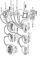
図1は、本発明が適用されたAVシステムの構成例を表している。このAVシステムにおいては、PCモジュール1、MPEG1ビデオデッキモジュール2、CD-ROMチェンジャモジュール3、DVD-ROM/ムービプレーヤモジュール4、およびデバイスベイモジュール5が、IEEE(Institute of Electrical and Electronics Engineers)1394ケーブル(以下、単に1394ケーブルと称する)6により、相互に接続されている。
【0028】
PCモジュール1は、いわゆるパーソナルコンピュータ(Personal Computer)であり、比較的限定された基本的な機能のみを有している。MPEG1ビデオデッキモジュール2は、MPEG(Moving Picture Experts Group)1の規格により定められているエンコーダとデコーダを有するとともに、ハードディスクを内蔵している。また、このMPEG1ビデオデッキモジュール2は、ビデオCDを駆動するドライバを有し、ビデオCDプレーヤとして、単独で使用することができるようになされている。
【0029】
CD-ROMチェンジャモジュール3は、内部に100枚乃至200枚のCD-ROMを内蔵し、その所定の1枚を選択し、内蔵するドライバで駆動するようになされている。このCD-ROMチェンジャモジュール3は、通常のCD(オーディオCD)が装着された場合には、CDプレーヤとして、単独で利用することができる。
【0030】
DVD-ROM/ムービプレーヤモジュール4は、その詳細な構成は図6を参照して後述するが、装着されたDVD-ROMを駆動するドライバを内蔵し、そこに記録されているデータを再生出力するようになされている。このDVD-ROM/ムービプレーヤモジュール4は、単独で使用された場合には、ムービプレーヤとして機能する。
【0031】
デバイスベイモジュール5は、例えば、インテル、コンパック(商標)などの規格に定められているパーツを装着することで、新たな機能を付加することができるようになされている。
【0032】
PCモジュール1には、モニタ13とスピーカ14が、信号線21を介して接続されており、PCモジュール1より出力された画像または音声を、それぞれ出力するようになされている。
【0033】
PCモジュール1にはまた、1394の規格に適合しないAV機器としてのカセットテープデッキ15、MD(Mini Disc)デッキ16、ビデオディスクプレーヤ17、テレビジョン受像機18、増幅器19、およびAVセレクタモジュール11が接続されている。PCモジュール1は、制御線12を介して、これらのAV機器を制御することができるようになされている。AVセレクタモジュール11にはまた、カセットテープデッキ15、MDデッキ16、ビデオディスクプレーヤ17、テレビジョン受像機18、および増幅器19が、それぞれ信号線21を介して接続されており、AVセレクタモジュール11は、接続されているAV機器のうちのいずれかから供給されるビデオ信号またはオーディオ信号を選択し、いずれかのAV機器に出力することができるようになされている。増幅器19にはまた、信号線21を介してスピーカ20が接続されている。
【0034】
図2は、1394ケーブル6の詳細な構成を表している。同図に示すように、1394ケーブル6は、外筒部31を有し、その内部に内筒部32と内筒部33を有している。内筒部32の内部には、線34Aと線34Bからなる、より線34が配置され、内筒部33の内部には、線35Aと線35Bからなる、より線35が配置されている。より線34とより線35が、それぞれ独立の信号経路を形成している。また、外筒部31の外部には、線36Aと線36Bが配置され、電力が供給されるようになされている。
【0035】
このように、PCモジュール1は、1394の規格に対応した機能を有するAV機器としてのMPEG1ビデオデッキモジュール2、CD-ROMチェンジャモジュール3、DVD-ROM/ムービプレーヤモジュール4、およびデバイスベイモジュール5に対しては、1394ケーブル6を介して制御信号、ビデオ信号、およびオーディオ信号を授受するようになされている。
【0036】
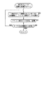
図3は、制御線12と信号線21の、より詳細な接続状態を示している。PCモジュール1は、コントロールS(Control-S)、コントロールA1(Control-A1)、およびLANCの3つの規格に基づく制御が可能となされており、制御線12としては、これらの規格に対応する制御線12A,12B,12Cにより構成されている。これらの制御線12A,12B,12Cは、それぞれ対応する規格のAV機器に接続されている。この実施の形態の場合、カセットテープデッキ15、AVセレクタ11、およびテレビジョン受像機18は、コントロールSの規格に基づく制御機能を有しているので、制御線12Aに相互に接続されている。MDデッキ16と増幅器19は、コントロールA1の規格に基づく制御機能を有しているので、制御線12Bに接続されている。また、ビデオディスクプレーヤ17は、LANCの規格に基づく制御機能を有しているので、制御線12Cに接続されている。
【0037】
なお、ここに示した各AV機器が、すべて同一の規格の制御機能を有しているAV機器である場合には、制御線12は1本でよいことはもとよりである。
【0038】
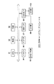
図4は、PCモジュール1の内部の構成例を表している。このPCモジュール1には、マザーボード41と、AVインタフェース(I/F)ボード42により構成されている。マザーボード41には、パーソナルコンピュータとして機能するための各種の部品が装着されている。すなわち、各種の処理を実行するCPU51、CPU51が各種の処理を行う上において必要なプログラムなどを記憶するROM52、およびCPU51が各種の処理を実行する上において必要なデータなどを適宜記憶するRAM53を有している。マザーボード41には、この他、公衆電話回線PSTN(Public Switched Telephone Network)に直接接続されるか、図示せぬ電話機またはファクシミリ装置などに接続されるモデム54を有している。モデム54は、電話回線を介して通信を実行する。ビデオキャプチャ55は、AVセレクタモジュール11からのビデオ信号の入力を受け、これを処理するようになされている。TV出力56は、マザーボード41からのビデオ信号をAVセレクタモジュール11に出力する。従って、ビデオキャプチャ55とTV出力56は、信号線21を介してAVセレクタモジュール11と接続されている。
【0039】
1394ケーブル6を介して授受されるデータを処理する1394インタフェース(I/F)57は、1394ケーブル6を介して、他のAV機器(この実施の形態の場合、MPEG1ビデオデッキモジュール2とDVD-ROM/ムービプレーヤモジュール4)に接続されている。グラフィックスアクセラレータ58は、グラフィックスデータを生成し、モニタ13に出力し、表示させるようになされている。また、オーディオ入出力59は、マザーボード41からのオーディオ信号をスピーカ14に出力するようになされている。
【0040】
AVインタフェースボード42には、コントロールパネル61と、IR(InfraRed)ブラスタ62が接続されている。AVインタフェースボード42は、コントロールパネル61またはIRブラスタ62からの入力に対応して、マザーボード41を制御するようになされている。
【0041】
図5は、AVインタフェースボード42の、より詳細な構成例を表している。AVインタフェースボード42は、マイクロコントローラ71を有し、コントロールパネル61の各種のスイッチからの入力に対応して、各種の処理を実行するようになされている。このマイクロコントローラ71はまた、コントロールパネル61のLEDの点灯を制御するようになされている。NVRAM(Nonvolatile Random Access Memory)72は、マイクロコントローラ71が電源オフ後も記憶する必要のあるデータなどを記憶するようになされている。通信バッファ73は、マザーボード41の拡張スロットとしてのISA(Industry Standard Architecture)または、USB(Universal Serial Bus)に接続されている。さらに、マイクロコントローラ71は、PS/2(Personal System 2)(商標)の規格に基づく信号をマザーボード41に出力するようになされている。
【0042】
IRブラスタ62は、赤外線キーボード(無線キーボード)81またはリモートコマンダ82の出力する赤外線信号を受信し、これを電気信号に変換してKBD信号またはSIRCS(Standard Code for Infrared Remote Control Systems)(商標)信号として、端子75からマイクロコントローラ71に出力するようになされている。また、IRブラスタ62は、マイクロコントローラ71から端子75を介してSIRCSの規格に基づく制御信号の入力を受け、赤外線信号として出力するようになされている。また、AVインタフェースボード42は、マザーボード41とIRブラスタ62との間において、IrDa(Infrared Data Association)の規格に基づく信号を授受するようになされている。
【0043】
AVインタフェースボード42の端子74には、コントロールS、コントロールA1、およびLANCの規格に基づく制御信号が入出力されるようになされている。すなわち、この端子74には、図3に示した制御線12A,12B,12Cが、それぞれ接続される。
【0044】
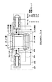
図6は、DVD-ROM/ムービプレーヤモジュール4の内部の構成例を表している。CPU91は、ROM92に記憶されているプログラムに従って、各種の処理を実行するようになされている。RAM93には、CPU91が各種の処理を実行する上において必要なデータなどが、適宜記憶される。ドライバ94は、DVD-ROM95を駆動する。デコーダ96は、DVD-ROM95より再生されたデータをデコードする処理を実行する。1394インタフェース97は、1394ケーブル6との間で、データの授受の処理を実行する。入出力インタフェース98には、入力部99と出力部100が接続され、入力部99からの入力に対応する信号をCPU91に出力するとともに、CPU91から出力されたデータを出力部100を介して出力するようになされている。
【0045】
PCモジュール1は、1394の規格外のAV機器の制御は、制御線12を介して行う。図7と図8は、この制御の例を表している。
【0046】
すなわち、図7の例においては、PCモジュール1は、制御線12Bを介してコントロールA1の規格に基づくコマンドをMDデッキ16に出力し、装着されているMDの再生を指令する。このコマンドが入力されたとき、MDデッキ16は、装着されているMDを再生し、その再生アナログオーディオ信号を信号線21を介して、AVセレクタモジュール11に出力する。
【0047】
PCモジュール1はまた、制御線12Aを介して、コントロールSの規格に基づくコマンドをAVセレクタモジュール11に出力し、AVセレクタモジュール11に、MDデッキ16より入力されたアナログビデオ信号を増幅器19とカセットテープ15に出力させる。また、PCモジュール1は、制御線12Bを介して、コントロールA1の規格に基づくコマンドを増幅器19に出力し、AVセレクタモジュール11より供給されたMDデッキ16からの再生信号を増幅し、スピーカ20に出力させる。
【0048】
さらに、PCモジュール1は、制御線12Aを介してコントロールSの規格に基づくコマンドをカセットテープデッキ15に出力し、AVセレクタモジュール11から出力されたMDデッキ16からの再生信号をカセットテープデッキ15に装着されているカセットテープに記録させる。さらにまた、PCモジュール1は、AVセレクタモジュール11から供給されたMDの再生信号を、そのオーディオ入出力59から、スピーカ14に出力し放音させる。
【0049】
図8の例においては、PCモジュール1は、制御線12Cを介して、LANCの規格に基づくコマンドを出力し、ビデオディスクプレーヤ17に装着されているビデオディスクを再生させる。そして、この再生信号を、信号線21を介してAVセレクタモジュール11に出力させる。PCモジュール1はまた、制御線12Aを介してAVセレクタモジュール11に、コントロールSの規格のコマンドを出力し、ビデオディスクプレーヤ17より供給されたアナログビデオ信号をテレビジョン受像機18に出力させると同時に、テレビジョン受像機18を制御線12Aを介して制御し、AVセレクタモジュール11より供給されたビデオ信号に対応した画像を表示させる。
【0050】
また、PCモジュール1は、制御線12Aを介してAVセレクタモジュール11を制御し、ビデオディスクプレーヤ17より供給されたビデオ信号を、PCモジュール1に供給させる。PCモジュール1は、このビデオ信号をビデオキャプチャ55で取り込み、必要に応じて、グラフィックスアクセラレータ58で、所定の画像をミックスした後、TV出力56から、AVセレクタモジュール11に出力する。PCモジュール1は、このミックス信号をテレビジョン受像機18に表示させる場合、制御線12Aを介してAVセレクタモジュール11を制御し、ビデオディスクプレーヤ17からのビデオ信号に変えて、PCモジュール1からのビデオ信号を選択させ、テレビジョン受像機18に出力させる。
【0051】
PCモジュール1は、さらに、モニタ13にミックス画像を表示させる場合、グラフィックスアクセラレータ58から、このミックス画像をモニタ13に出力する。
【0052】
次に、PCモジュール1により、1394ケーブル6を介して、それに接続されているAV機器を制御する場合の動作について説明する。PCモジュール1は、その電源がオンされたとき、図9のフローチャートに示す初期化処理を実行する。最初にステップS1において、PCモジュール1のCPU51は、1394ケーブル6を介して接続されている1つのAV機器(例えば、DVD-ROM/ムービプレーヤモジュール4)に対して、そのアイコン図形データ(ユーザインタフェース情報)の転送を要求する。DVD-ROM/ムービプレーヤモジュール4は、そのROM92に、自分自身に対するアイコン図形データ(図10におけるアイコン114に対応する図形データ)を記憶している。DVD-ROM/ムービプレーヤモジュール4のCPU91は、PCモジュール1から1394ケーブル6を介して、この要求を受けたとき、図11のステップS11に示す処理を実行し、ROM92に記憶されているアイコン図形データを読み出し、1394インタフェース97を介して、1394ケーブル6に出力させる。
【0053】
このアイコン図形データは、ステップS2で、PCモジュール1の1394インタフェース57で取り込まれ、CPU51に供給される。CPU51は、このように取り込んだアイコン図形データを受信すると、RAM53に、これを記憶させる。
【0054】
なお、ユーザインタフェース情報としては、ボタン図形などの画像データ、その配置位置を示すレイアウト情報、ボタンの意味などを示すテキスト(文字)、およびスクリプト(プログラム)を含めることができる。そして、これらのユーザインタフェース情報は、HTML(Hyper Text Markup Language)とJavaScript(商標)により記述することができる。
【0055】
次に、ステップS3に進み、CPU51は、1394ケーブル6に接続されているすべてのAV機器からアイコン図形データを受信したか否かを判定し、まだ、アイコン図形データを受信していないAV機器が存在する場合には、ステップS1に戻り、同様の処理を実行する。
【0056】
同様にして、PCモジュール1は、MPEG1ビデオデッキモジュール2、CD-ROMチェンジャモジュール3、およびデバイスベイモジュール5から、図10に示すアイコン図形データ112,113,115を受信し、これをRAM53に記憶させる。ステップS3において、1394ケーブル6に接続されているすべてのAV機器からアイコン図形データの転送を受けたと判定された場合、初期化処理が終了される。
【0057】
次に、図12のフローチャートを参照して、PCモジュール1を介して1394ケーブル6に接続されているAV機器の動作を制御する場合の処理例について説明する。最初に、ステップS21において、ユーザは、例えば赤外線キーボード81の所定のキーを操作して、AV機器選択画面の表示を指令する。赤外線キーボード81の所定のキーを操作すると、その操作されたキーに対応する赤外線信号が、赤外線キーボード81より出力され、IRブラスタ62で受信される。IRブラスタ62は、この受信した信号に対応する電気信号をマイクロコントローラ71に出力する。マイクロコントローラ71は、赤外線キーボード81からの所定のキーに対応する信号の入力を受けたとき、この信号に対応する信号をマザーボード41のCPU51に出力する。
【0058】
CPU51は、この信号の入力を受けたとき、ROM53に記憶されているアイコン図形データを読み出し、グラフィックスアクセラレータ58に出力させる。グラフィックスアクセラレータ58は、入力されたアイコン図形データをビットマップデータに変換し、モニタ13に出力し、表示させる。このようにして、例えば、図10に示すような、1394ケーブル6に接続されている各AV機器のアイコン図形112乃至115が表示される。また、このときPCモジュール1は、ROM52に予め記憶されている自分自身のアイコン図形データも読み出し、図10に示すように、アイコン図形111として表示させる。
【0059】
ユーザは、図10に示すように、表示されたアイコン図形の中から、所定のアイコン図形を選択することで、使用するAV機器を指定する。この指定の操作は、赤外線キーボード81の所定のキーを操作し、カーソル(図示せず)で指定することで行われる。この操作が行われたとき、上述した場合と同様のキー信号が、IRブラスタ62、マイクロコントローラ71を介してCPU51に入力される。CPU51は、ステップS22で、いずれかのアイコン図形が選択されるまで待機し、いずれかのアイコン図形が選択されたと判定された場合、ステップS23に進む。
【0060】
ステップS23において、CPU51は、選択されたAV機器に対して、そのAV機器の操作ボタンの表示データ(そのAV機器を制御するのに必要なユーザインタフェース情報)の転送を要求する。すなわち、CPU51は、この転送を要求するコマンドを発生し、1394インタフェース57を介して1394ケーブル6に出力する。例えば、いまDVD-ROM/ムービプレーヤモジュール4のアイコン図形114が選択されたとすると、CPU51は、DVD-ROM/ムービプレーヤモジュール4に対して、その操作(制御)に必要なボタンの表示データ(例えば、図13に示すような表示データ)の転送を要求する。図14を参照して後述するように、この要求を受けたDVD-ROM/ムービプレーヤモジュール4は、このコマンドを受け取ったとき、ステップS31において、自分自身を制御するのに必要なボタンの表示データを1394ケーブル6を介して出力する。
【0061】
DVD-ROM/ムービプレーヤモジュール4が、その表示データを1394ケーブル6を介して出力したとき、PCモジュール1のCPU51は、ステップS24において、1394インタフェース57を介して、この表示データを受信し、RAM53に記憶させる。CPU51は、さらに、ステップS25において、RAM53に記憶した表示データを読み出させ、グラフィックスアクセラレータ58に出力し、ビットマップデータに変換して、モニタ13に出力し、表示させる。
【0062】
このようにして、モニタ13には、例えば、図13に示すようなDVD-ROM/ムービプレーヤモジュール4を操作する上において必要なボタンなどが表示される。図13の表示例においては、DVD-ROM/ムービプレーヤモジュール4の名称として、「DVD-ROMプレーヤ」の文字が表示されている。また、その下には、巻戻し、停止、再生、早送りの各操作を指令するとき操作されるボタンが表示され、さらにその下には、トラックを指定するためのボタンが表示されている。
【0063】
PCモジュール1のCPU51は、次にステップS26において、図13に示すボタンのいずれかが操作されるまで待機する。ユーザは、モニタ13に表示されているボタンのいずれかを赤外線キーボード81を操作することで選択する。ステップS26において、いずれかのボタンが選択されたと判定された場合、ステップS27に進み、CPU51は、操作されたボタンに対応するモニタ13上における座標(操作されたボタンを識別する情報)を検出し、1394インタフェース57を介してDVD-ROM/ムービプレーヤモジュール4に出力する。DVD-ROM/ムービプレーヤモジュール4においては、後述するように、この位置座標の入力を受けると、その位置で規定されるボタンに対応する処理を、図14のステップS33で実行することになる。
【0064】
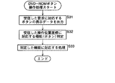
次に、図14のフローチャートを参照して、DVD-ROM/ムービプレーヤモジュール4の動作について説明する。最初にステップS31において、DVD-ROM/ムービプレーヤモジュール4のCPU91は、図12のステップS23において、PCモジュール1が出力したコマンドを1394インタフェース97を介して受信すると、ROM92に予め記憶されている、図13に示すようなボタンの表示データを読み出し、1394インタフェース97を介してPCモジュール1に出力させる。上述したように、PCモジュール1においては、このようにして、DVD-ROM/ムービプレーヤモジュール4より出力された表示データを図12のステップS24において受信する。
【0065】
さらに上述したようにして、図13に示すボタンのいずれかが操作された場合において、PCモジュール1が、ステップS27において、その操作位置に対応する座標を出力したとき、DVD-ROM/ムービプレーヤモジュール4のCPU91は、この座標データを1394インタフェース97を介して受信する。このデータを受信したとき、CPU91は、ステップS32において、受信した位置座標に対応する機能(ボタン)が、どのような機能であるのかを判定する。例えば、その座標は、再生ボタンに対応するのか、早送りボタンに対応するのか、巻戻しボタンに対応するのか、といったことを判定する。そして、ステップS33に進み、ステップS32で判定した機能に対応する処理を実行する。例えば、ステップS32において、再生ボタンが操作されたと判定された場合、CPU91は、ドライバ94を制御し、DVD-ROM95を再生させる。あるいはまた、早送りボタンが操作されたと判定された場合、DVD-ROM95を早送りさせる。
【0066】
DVD-ROM95より再生されたデータは、デコーダ96でデコードされた後、1394インタフェース97を介して、1394ケーブル6に出力される。PCモジュール1は、1394ケーブル6を介して入力されたデータを1394インタフェース57を介して受信し、そのビデオデータをグラフィックスアクセラレータ58に出力し、そのオーディオデータをオーディオ入出力59に出力する。グラフィックスアクセラレータ58は、入力されたビデオデータをビットマップデータを変換し、モニタ13に出力し、表示させる。また、オーディオ入出力59は、入力されたオーディオ信号をスピーカ14に出力し、放音させる。このようにして、モニタ13とスピーカ14を利用して、DVD-ROM95より再生された画像と音声を視聴することができる。
【0067】
図15は、以上のようにして、1394ケーブル6に接続されているAV機器のユーザインタフェース情報を、PCモジュール1に読み込む動作を模式的に表している。同図に示すように、この実施の形態においては、AV機器121(図1のMPEG1ビデオデッキモジュール2、CD-ROMチェンジャモジュール3、DVD-ROM/ムービプレーヤモジュール4、またはデバイスベイモジュール5に対応する)が、単独で、あるいはAV機器122と組み合わせた状態で、独立して(PCモジュール1を利用せずに)使用することが可能とされている。
【0068】
しかしながら、このAV機器121を1394ケーブル6を介してPCモジュール1に接続し、PCモジュール1で制御する場合には、AV機器121に、予め記憶されているユーザインタフェース情報を1394ケーブル6を介してPCモジュール1に転送、記憶させる。換言すれば、PCモジュール1には、他のAV機器のユーザインタフェース情報が、最初は記憶されていない。そして、1394ケーブル6にAV機器121が接続されると、その接続されたAV機器121自身に予め記憶されているユーザインタフェース情報(UI)がPCモジュール1に、自動的に(ユーザの特別の操作を経ることなく)転送される。
【0069】
従って、ユーザは、AV機器121を購入したとき、これをPCモジュール1で制御するためのソフトウエア(ユーザインタフェース情報)を、PCモジュール1にインストールする操作を行う必要がない。単に、AV機器121を1394ケーブル6に接続し、電源をオンするだけで、インストール処理が自動的に行われることになる。
【0070】
このように、この実施の形態においては、各種の専門的な処理は、各AV機器(外部電子機器)に行わせるようにしているため、PCモジュール1は、コンピュータとしては、極めて基礎的な機能のみを有するものとして構成することができる。すなわち、図16に示すように、ビデオエンタテインメント、ゲーム、マルチメディアクリエーション、アートおよびグラフィックス、通信、オフィスユースといった、各種の項目におけるPCモジュール1のレベルは低く、図17のオールインワンのパーソナルコンピュータの各項目と比較して明らかなように、いずれも基礎的な機能しか有していない。
【0071】
そして、例えば、ビデオエンタテインメントやマルチメディアクリエーションといった分野において、このAVシステムを利用する場合には、その分野において、高度な機能を有するモジュール(VAM1またはVAM2)を購入し、これを1394ケーブル6に接続するようにする。このようにすれば、使用することがほとんどない項目において、高度な機能を予め設けておく必要がなくなり、PCモジュール1の構成を簡略化し、低コスト化することができる。そして、所定の項目において、高度の機能を有するモジュールをPCモジュール1に接続することで、自分が利用する項目についてだけ、全体的に高度なAVシステムを実現することが可能となる。
【0072】
従って、インストールの操作が不要となるばかりでなく、PCモジュールを先を購入し、後から、新たな機能を付加するためのモジュールを購入したような場合においても、その新たなモジュールには、それを制御するための対応する新しいバージョンのソフトウエア(プログラム)が予め記憶されているので、バージョンの不一致により、動作が不能となるようなことが防止される。
【0073】
さらに、周辺機器としてのAV機器は、それを制御するユーザインタフェース情報を内蔵させるように構成することができるので、PCモジュール1の機能に拘束されずに、各周辺機器(この実施の形態の場合、AV機器)の独自性を、その設計メーカーが発揮することが可能となる。
【0074】
なお、上記実施の形態においては、ホームバスとして1394を使用するようにしたが、その他のホームバスを使用することも可能である。
【0075】
また、上記実施の形態においては、外部周辺機器として、AV機器を例としたが、その他の電子機器とすることも可能であるのはもちろんである。
【0076】
【発明の効果】
以上の如く、請求項1に記載の電子機器制御装置および請求項7に記載の電子機器制御方法によれば、外部電子機器に対して、それを制御する上において必要なユーザインタフェース情報の伝送を要求して、ユーザインタフェース情報の伝送を制御し、この要求に対応して伝送されてきたユーザインタフェース情報を記憶するようにしたので、ユーザの手動操作によるインストール操作が不要となり、操作性が向上する。また、新たな外部電子機器が提供されたような場合において、これを制御する機能を有しないとの理由で、電子機器制御装置が陳腐化してしまうことが抑制される。
【0077】
請求項8に記載の電子機器および請求項10に記載の電子機器制御方法によれば、電子機器制御装置による制御に基づいた要求に対応して、予め記憶してあるユーザインタフェース情報を電子機器制御装置に伝送するようにしたので、インストール操作をしなくとも、電子機器制御装置で、制御可能な電子機器を実現することが可能となる。また、電子機器の独自性を発揮することが容易となる。さらに、電子機器制御装置のソフトウエアのバージョンに拘らず、最新の機能を有する電子機器を実現することが可能となる。
【0078】
請求項11に記載の電子機器制御装置および請求項12に記載の電子機器制御方法によれば、第1の電子機器に予め記憶されているユーザインタフェース情報を第2の電子機器に伝送し、記憶するようにしたので、必要な分野についてだけ、高度な機能を有するシステムを、低コストで実現することが可能となる。
【図面の簡単な説明】
【図1】本発明を適用したAVシステムの構成例を示す図である。
【図2】図1の1394ケーブルの構成を示す図である。
【図3】図1の制御線のより詳細な接続状態を示す図である。
【図4】図1のPCモジュールの内部の構成例を示すブロック図である。
【図5】図4のAVインタフェースボードの構成例を示す図である。
【図6】図1のDVD-ROM/ムービプレーヤモジュールの内部の構成例を示すブロック図である。
【図7】MDデッキからの再生信号をカセットテープデッキに記録する場合の動作を説明するための図である。
【図8】ビデオディスクプレーヤからの再生信号をモニタする場合の動作を説明するための図である。
【図9】図1のPCモジュールの初期化時の動作を説明するフローチャートである。
【図10】AV機器のアイコン図形の表示例を示す図である。
【図11】 DVD-ROM/ムービプレーヤモジュールの初期化時の処理を説明するフローチャートである。
【図12】PCモジュールのAV機器選択時の処理を説明するフローチャートである。
【図13】 DVD-ROM/ムービプレーヤモジュールの制御のためのボタンの表示例を示す図である。
【図14】 DVD-ROM/ムービプレーヤモジュールのボタン操作時の処理を説明するフローチャートである。
【図15】ユーザインタフェース情報の伝送を説明する図である。
【図16】PCモジュールとこれに付加される他のモジュールの機能を説明する図である。
【図17】オールインワンのパーソナルコンピュータの機能を説明する図である。
【符号の説明】
1 PCモジュール, 2 MPEG1ビデオデッキモジュール, 3 CD-ROMチェンジャモジュール, 4 DVD-ROM/ムービプレーヤモジュール, 5 デバイスベイモジュール, 6 1394ケーブル, 11 AVセレクタモジュール,12 制御線, 13 モニタ, 14 スピーカ, 41 マザーボード,42 AVインタフェースボード, 51 CPU, 52 ROM, 53 RAM, 57 1394インタフェース, 58 グラフィックスアクセラレータ, 61 コントロールパネル, 62 IRブラスタ, 91 CPU, 92 ROM,93 RAM, 95 DVD-ROM, 96 デコーダ, 97 1394インタフェース[0001]
BACKGROUND OF THE INVENTION
The present invention relates to an electronic device control apparatus and method, and an electronic device.Multiple electronic devicesThe present invention relates to an electronic device control apparatus and method that eliminates the need for installing software for controlling an electronic device and improves operability, and the electronic device.
[0002]
[Prior art]
Recently, personal computers have become widespread and have been used not only at work but also at home. In many cases, so-called AV (Audio Visual) devices such as a television receiver, a cassette tape deck, and a video disc player are provided at home. In such a case, it is conceivable that the personal computer and each AV device are connected by a home bus so that each AV device can be centrally controlled by the personal computer.
[0003]
As a result, personal computers are often referred to as computers generally referred to as all-in-one.
[0004]
That is, as shown in FIG. 17, this all-in-one personal computer can be used in various fields such as video entertainment, games, multimedia creation, art and graphics, communication, and office use. It is configured as having a function.
[0005]
[Problems to be solved by the invention]
However, when the personal computer has an all-in-one configuration as described above, there is a problem that the configuration becomes complicated and the cost is increased.
[0006]
When an AV device that is not scheduled by the personal computer is connected via the home bus, software for controlling the newly connected AV device (peripheral device) for the personal computer ( Program) must be installed by performing a predetermined operation. Accordingly, the user needs knowledge necessary for installation, and those who do not have the knowledge have a problem that the peripheral device cannot be controlled by the personal computer.
[0007]
Furthermore, even a user who has knowledge for installation must perform an installation operation, and in particular, when a plurality of personal computers are connected on the home bus, On the other hand, it has to be troublesome to install each.
[0008]
In addition, it is possible to incorporate a lot of software in advance so that many external peripheral devices can be controlled in the personal computer, but the system is upgraded by adding external peripheral devices sequentially. In such a case, the version of software pre-installed in the personal computer becomes out of date and the newly purchased peripheral device may not be controlled. In such a case, it is necessary to install a new version of software corresponding to the new peripheral device on the personal computer.
[0009]
Furthermore, if software is installed in a personal computer in advance, peripheral device manufacturers are bound by the specifications of the personal computer software, making it difficult to incorporate the uniqueness of the peripheral device manufacturer into the peripheral device. There was a problem to become.
[0010]
The present invention has been made in view of such a situation, and eliminates the need for an installation operation and allows the uniqueness of peripheral devices to be exhibited.
[0011]
[Means for Solving the Problems]
The electronic device control apparatus according to claim 1 requests a communication means for communicating with an external electronic device, and transmission of user interface information necessary for controlling the external electronic device to the external electronic device, Control means for controlling transmission of interface information, and storage means for storing user interface information transmitted from an external electronic device,User interface information HTML Is described usingWhen the external electronic device is selected, the control unit requests the selected external electronic device to transmit user interface information.
[0012]
Claim7The electronic device control method according to
[0013]
Claim8The electronic device described in 1 is a communication unit that communicates with the electronic device control device, a storage unit that stores user interface information necessary for controlling itself, and user interface information based on control by the electronic device control device. A transmission means for transmitting user interface information to the electronic device control device when receiving a transmission request;The user interface information is HTML Is described usingIt is characterized by that.
[0014]
Claim10The electronic device control method described in 1 is a communication step for communicating with an electronic device control device, a storage step for storing user interface information necessary for controlling itself, and a user interface based on control by the electronic device control device A transmission step of transmitting user interface information to the electronic device control device when receiving a request for information transmission;The user interface information includes HTML Is described usingIt is characterized by that.
[0015]
Claim11In the electronic device control apparatus described in 1), the first electronic device stores the first communication means that communicates with the second electronic device, and the first memory that stores user interface information necessary for controlling itself. And first transmission means for reading the user interface information from the first storage means and transmitting it to the second electronic equipment when receiving a request for transmission of the user interface information based on the control by the means and the second electronic equipment And the second electronic device includes second communication means for communicating with the first electronic device, and user interface information necessary for controlling the first electronic device with respect to the first electronic device. Control means for requesting transmission of user interface information and controlling transmission of user interface information; and second storage means for storing user interface information transmitted from the first electronic device.User interface information HTML Is described usingThe control means requests the user interface information to be transmitted to the selected first electronic device when the first electronic device is selected.
[0016]
Claim12The first electronic device has a first communication step for communicating with the second electronic device, and a first storage for storing user interface information necessary for controlling itself. And a first transmission step of reading the stored user interface information and transmitting it to the second electronic device when receiving a request for transmission of the user interface information based on control by the second electronic device. The second electronic device includes a second communication step for communicating with the first electronic device, and transmission of user interface information necessary for controlling the first electronic device to the first electronic device. And a control step for controlling the transmission of user interface information and a second for storing the user interface information transmitted from the first electronic device. And a 憶 step,User interface information HTML Is described usingThe control step is characterized by requesting transmission of user interface information to the selected first electronic device when the first electronic device is selected.
[0017]
The electronic device control apparatus according to
[0018]
Claim8Electronic equipment and claims10In the electronic device control method described in the above, when there is a request based on control by the electronic device control apparatus, user interface information is transmitted.User interface information HTML It is described using.
[0019]
Claim11Electronic device control apparatus according to claim and claim12When the second electronic device requests the first electronic device to transmit and controls the transmission of user interface information, the first electronic device responds accordingly. The user interface information is transmitted to the second electronic device. The second electronic device stores this user interface information.User interface information HTML It is described using.
[0020]
DETAILED DESCRIPTION OF THE INVENTION
Embodiments of the present invention will be described below, but in order to clarify the correspondence between each means of the invention described in the claims and the following embodiments, in parentheses after each means, The features of the present invention will be described with the corresponding embodiment (however, an example) added. However, of course, this description does not mean that each means is limited to the description.
[0021]
The electronic device control apparatus according to
[0022]
The electronic device control apparatus according to
[0023]
Claim5When the user interface information is selected, the electronic device control apparatus described in 1) further includes supply means (for example, step S27 in FIG. 12) for supplying the selection information to the external electronic device.
Claim6The electronic device control device described in 1 is a display unit (for example, step S21 in FIG. 12) that displays an icon corresponding to each of one or more connected external electronic devices, and the icon displayed on the display unit. Selection means (for example, Step S22 of Drawing 12) which chooses an external electronic device corresponding to the selected predetermined icon by selecting a predetermined icon is provided.
[0024]
Claim8The electronic device described in 1 is a communication unit (for example, the 1394 interface 97 in FIG. 6) that communicates with the electronic device control apparatus, and a storage unit (for example, FIG. 6) that stores user interface information necessary for controlling itself. ROM 92) and transmission means (for example, step S31 in FIG. 14) for transmitting user interface information to the electronic device control device when a request for transmission of user interface information based on control by the electronic device control device is received. PreparationThe user interface information is HTML Is described usingIt is characterized by that.
[0025]
Claim9When any of the electronic device user interface information described in the above is selected, processing means (for example, step S33 in FIG. 14) that performs processing corresponding to the selection information when the selection information output from the electronic device control apparatus is received. ) Is further provided.
[0026]
Claim11The first electronic device is necessary for controlling the first electronic device and the first communication means (for example, the 1394 interface 97 in FIG. 6) that communicates with the second electronic device. When receiving a request for transmission of user interface information based on the control by the first storage means (for example,
[0027]
FIG. 1 shows a configuration example of an AV system to which the present invention is applied. In this AV system, a
[0028]
The
[0029]
The CD-
[0030]
The detailed configuration of the DVD-ROM /
[0031]
The
[0032]
A monitor 13 and a
[0033]
The
[0034]
FIG. 2 shows a detailed configuration of the 1394
[0035]
As described above, the
[0036]
FIG. 3 shows a more detailed connection state between the control line 12 and the
[0037]
It should be noted that if the AV devices shown here are all AV devices having the same standard control function, it is needless to say that one control line 12 is sufficient.
[0038]
FIG. 4 shows an internal configuration example of the
[0039]
A 1394 interface (I / F) 57 for processing data transmitted / received via the 1394
[0040]
A control panel 61 and an IR (InfraRed)
[0041]
FIG. 5 shows a more detailed configuration example of the
[0042]
The
[0043]
Control signals based on the control S, control A1, and LANC standards are inputted to and outputted from the terminals 74 of the
[0044]
FIG. 6 shows an internal configuration example of the DVD-ROM /
[0045]
The
[0046]
That is, in the example of FIG. 7, the
[0047]
The
[0048]
Further, the
[0049]
In the example of FIG. 8, the
[0050]
Further, the
[0051]
When the
[0052]
Next, an operation when the
[0053]
The icon graphic data is captured by the 1394
[0054]
Note that the user interface information can include image data such as button graphics, layout information indicating the arrangement position, text (characters) indicating the meaning of the buttons, and script (program). These user interface information can be described in HTML (Hyper Text Markup Language) and JavaScript (trademark).
[0055]
In step S3, the
[0056]
Similarly, the
[0057]
Next, a processing example in the case of controlling the operation of the AV equipment connected to the 1394
[0058]
When receiving this signal input, the
[0059]
As shown in FIG. 10, the user designates an AV device to be used by selecting a predetermined icon figure from the displayed icon figures. This designation operation is performed by operating a predetermined key of the infrared keyboard 81 and designating with a cursor (not shown). When this operation is performed, a key signal similar to that described above is input to the
[0060]
In step S23, the
[0061]
When the DVD-ROM /
[0062]
Thus, for example, buttons necessary for operating the DVD-ROM /
[0063]
Next, in step S26, the
[0064]
Next, the operation of the DVD-ROM /
[0065]
Further, as described above, when any of the buttons shown in FIG. 13 is operated, when the
[0066]
Data reproduced from the DVD-
[0067]
FIG. 15 schematically shows the operation of reading the user interface information of the AV device connected to the 1394
[0068]
However, when the
[0069]
Therefore, when the user purchases the
[0070]
Thus, in this embodiment, since various specialized processes are performed by each AV device (external electronic device), the
[0071]
For example, when using this AV system in the field of video entertainment or multimedia creation, a module (VAM1 or VAM2) having advanced functions is purchased in this field and connected to the 1394
[0072]
Therefore, not only is the installation operation unnecessary, but even when a PC module is purchased first and a module for adding a new function is purchased later, the new module includes Since the corresponding new version of software (program) for controlling is stored in advance, it is possible to prevent the operation from being disabled due to version mismatch.
[0073]
Furthermore, since an AV device as a peripheral device can be configured to incorporate user interface information for controlling it, each peripheral device (in the case of this embodiment) is not restricted by the function of the
[0074]
In the above embodiment, 1394 is used as the home bus, but other home buses can also be used.
[0075]
In the above embodiment, an AV device is taken as an example of the external peripheral device, but it is needless to say that other electronic devices can be used.
[0076]
【The invention's effect】
As described above, the electronic device control device according to
[0077]
Claim8Electronic equipment and claims10According to the electronic device control method described in the above, the user interface information stored in advance is transmitted to the electronic device control device in response to the request based on the control by the electronic device control device. Even if it does not, it becomes possible to implement | achieve the electronic device which can be controlled with an electronic device control apparatus. In addition, it becomes easy to demonstrate the uniqueness of the electronic device. Furthermore, an electronic device having the latest function can be realized regardless of the software version of the electronic device control apparatus.
[0078]
Claim11Electronic device control apparatus according to claim and claim12According to the electronic device control method described in the above, the user interface information stored in advance in the first electronic device is transmitted to and stored in the second electronic device. A system having a function can be realized at low cost.
[Brief description of the drawings]
FIG. 1 is a diagram showing a configuration example of an AV system to which the present invention is applied.
FIG. 2 is a diagram illustrating a configuration of the 1394 cable of FIG.
FIG. 3 is a diagram showing a more detailed connection state of the control lines in FIG. 1;
4 is a block diagram showing an example of the internal configuration of the PC module shown in FIG. 1;
FIG. 5 is a diagram illustrating a configuration example of the AV interface board of FIG. 4;
6 is a block diagram showing an example of the internal configuration of the DVD-ROM / movie player module of FIG. 1. FIG.
FIG. 7 is a diagram for explaining an operation when a reproduction signal from an MD deck is recorded on a cassette tape deck.
FIG. 8 is a diagram for explaining an operation in the case of monitoring a reproduction signal from a video disc player.
FIG. 9 is a flowchart illustrating an operation at the time of initialization of the PC module of FIG. 1;
FIG. 10 is a diagram illustrating a display example of an icon graphic of an AV device.
FIG. 11 is a flowchart for explaining processing at the time of initialization of a DVD-ROM / movie player module;
FIG. 12 is a flowchart illustrating processing when an AV device is selected by the PC module.
FIG. 13 is a diagram showing a display example of buttons for controlling the DVD-ROM / movie player module.
FIG. 14 is a flowchart for explaining processing when a button of the DVD-ROM / movie player module is operated;
FIG. 15 is a diagram illustrating transmission of user interface information.
FIG. 16 is a diagram for explaining functions of a PC module and other modules added to the PC module;
FIG. 17 is a diagram illustrating functions of an all-in-one personal computer.
[Explanation of symbols]
1 PC module, 2 MPEG1 video deck module, 3 CD-ROM changer module, 4 DVD-ROM / movie player module, 5 device bay module, 6 1394 cable, 11 AV selector module, 12 control line, 13 monitor, 14 speaker, 41 Motherboard, 42 AV Interface Board, 51 CPU, 52 ROM, 53 RAM, 57 1394 Interface, 58 Graphics Accelerator, 61 Control Panel, 62 IR Blaster, 91 CPU, 92 ROM, 93 RAM, 95 DVD-ROM, 96 Decoder 97 1394 interface
Claims (12)
前記外部電子機器と通信する通信手段と、
前記外部電子機器に対して、前記外部電子機器を制御する上において必要なユーザインタフェース情報の伝送を要求して、前記ユーザインタフェース情報の伝送を制御する制御手段と、
前記外部電子機器から伝送されてきた前記ユーザインタフェース情報を記憶する記憶手段と
を備え、
前記ユーザインタフェース情報は、 HTML を用いて記述され、
前記制御手段は、前記外部電子機器が選択されたとき、選択された前記外部電子機器に前記ユーザインタフェース情報の伝送を要求する
ことを特徴とする電子機器制御装置。In an electronic device control apparatus to which one or more external electronic devices are connected,
Communication means for communicating with the external electronic device;
Control means for requesting the external electronic device to transmit user interface information necessary for controlling the external electronic device, and controlling the transmission of the user interface information;
Storage means for storing the user interface information transmitted from the external electronic device,
Wherein the user interface information is described Using HTML, a
When the external electronic device is selected, the control means requests the selected external electronic device to transmit the user interface information.
ことを特徴とする請求項1に記載の電子機器制御装置。The electronic device control apparatus according to claim 1, further comprising an output unit that outputs the user interface information stored in the storage unit in order to display the user interface information.
ことを特徴とする請求項1に記載の電子機器制御装置。The electronic device control apparatus according to claim 1, wherein the user interface information includes at least one of image data, layout information, text, and a script.
前記外部電子機器と、ホームバスを介して接続される
ことを特徴とする請求項1に記載の電子機器制御装置。The external electronic device is an AV device,
The electronic device control device according to claim 1, wherein the electronic device control device is connected to the external electronic device via a home bus.
ことを特徴とする請求項1に記載の電子機器制御装置。The electronic device control apparatus according to claim 1, further comprising a supply unit that supplies the selection information to the external electronic device when the user interface information is selected.
前記表示手段に表示された前記アイコンの中から所定のアイコンが選択されることで、選択された所定のアイコンに対応する前記外部電子機器を選択する選択手段と
を備えることを特徴とする請求項1に記載の電子機器制御装置。Display means for displaying an icon corresponding to each of the one or more connected external electronic devices;
And a selection unit that selects the external electronic device corresponding to the selected predetermined icon when a predetermined icon is selected from the icons displayed on the display unit. The electronic device control apparatus according to 1.
前記外部電子機器と通信する通信ステップと、
前記外部電子機器に対して、前記外部電子機器を制御する上において必要なユーザインタフェース情報の伝送を要求して、前記ユーザインタフェース情報の伝送を制御する制御ステップと、
前記外部電子機器から伝送されてきた前記ユーザインタフェース情報を記憶する記憶ステップと
を含み、
前記ユーザインタフェース情報は、 HTML を用いて記述され、
前記制御ステップは、前記外部電子機器が選択されたとき、選択された前記外部電子機器に前記ユーザインタフェース情報の伝送を要求する
ことを特徴とする電子機器制御方法。In an electronic device control method of an electronic device control apparatus to which one or more external electronic devices are connected,
A communication step of communicating with the external electronic device;
A control step of requesting the external electronic device to transmit user interface information necessary for controlling the external electronic device, and controlling the transmission of the user interface information;
Storing the user interface information transmitted from the external electronic device, and
Wherein the user interface information is described Using HTML, a
The control step requests the selected external electronic device to transmit the user interface information when the external electronic device is selected.
前記電子機器制御装置と通信する通信手段と、
自分自身を制御する上において必要なユーザインタフェース情報を記憶する記憶手段と、
前記電子機器制御装置による制御に基づいた前記ユーザインタフェース情報の伝送の要求を受けたとき、前記ユーザインタフェース情報を前記電子機器制御装置に伝送する伝送手段と
を備え、
前記ユーザインタフェース情報は、 HTML を用いて記述される
ことを特徴とする電子機器。In an electronic device connected to an electronic device control device,
Communication means for communicating with the electronic device control device;
Storage means for storing user interface information necessary for controlling itself;
Transmission means for transmitting the user interface information to the electronic device control device when receiving a request for transmission of the user interface information based on control by the electronic device control device;
With
The electronic device , wherein the user interface information is described using HTML .
ことを特徴とする請求項8に記載の電子機器。The apparatus further comprises processing means for performing processing corresponding to the selection information when the selection information output from the electronic device control apparatus is received when any of the user interface information is selected. 8. The electronic device according to 8 .
前記電子機器制御装置と通信する通信ステップと、
自分自身を制御する上において必要なユーザインタフェース情報を記憶する記憶ステップと、
前記電子機器制御装置による制御に基づいた前記ユーザインタフェース情報の伝送の要求を受けたとき、前記ユーザインタフェース情報を前記電子機器制御装置に伝送する伝送ステップと
を含み、
前記ユーザインタフェース情報は、 HTML を用いて記述される
ことを特徴とする電子機器制御方法。In an electronic device control method for an electronic device connected to an electronic device control device,
A communication step of communicating with the electronic device control device;
A storage step for storing user interface information necessary for controlling itself;
A transmission step of transmitting the user interface information to the electronic device control device when receiving a request for transmission of the user interface information based on control by the electronic device control device;
Including
The method of controlling an electronic device , wherein the user interface information is described using HTML .
前記第1の電子機器は、
前記第2の電子機器と通信する第1の通信手段と、
自分自身を制御する上において必要なユーザインタフェース情報を記憶する第1の記憶手段と、
前記第2の電子機器による制御に基づいた前記ユーザインタフェース情報の伝送の要求を受けたとき、前記ユーザインタフェース情報を前記第1の記憶手段から読み出し、前記第2の電子機器に伝送する第1の伝送手段と
を備え、
前記第2の電子機器は、
前記第1の電子機器と通信する第2の通信手段と、
前記第1の電子機器に対して、前記第1の電子機器を制御する上において必要なユーザインタフェース情報の伝送を要求して、前記ユーザインタフェース情報の伝送を制御する制御手段と、
前記第1の電子機器から伝送されてきた前記ユーザインタフェース情報を記憶する第2の記憶手段と
を備え、
前記ユーザインタフェース情報は、 HTML を用いて記述され、
前記制御手段は、前記第1の電子機器が選択されたとき、選択された前記第1の電子機器に前記ユーザインタフェース情報の伝送を要求する
ことを特徴とする電子機器制御装置。In an electronic device control apparatus constituted by a first electronic device connected to each other and a second electronic device that controls the first electronic device,
The first electronic device includes:
First communication means for communicating with the second electronic device;
First storage means for storing user interface information necessary for controlling itself;
When receiving a request for transmission of the user interface information based on control by the second electronic device, the user interface information is read from the first storage unit and transmitted to the second electronic device. Transmission means, and
The second electronic device is
Second communication means for communicating with the first electronic device;
Control means for requesting transmission of user interface information necessary for controlling the first electronic device to the first electronic device, and controlling transmission of the user interface information;
Second storage means for storing the user interface information transmitted from the first electronic device,
Wherein the user interface information is described Using HTML, a
The control device requests the transmission of the user interface information to the selected first electronic device when the first electronic device is selected.
前記第1の電子機器は、
前記第2の電子機器と通信する第1の通信ステップと、
自分自身を制御する上において必要なユーザインタフェース情報を記憶する第1の記憶ステップと、
前記第2の電子機器による制御に基づいた前記ユーザインタフェース情報の伝送の要求を受けたとき、記憶されている前記ユーザインタフェース情報を読み出し、前記第2の電子機器に伝送する第1の伝送ステップと
を含み、
前記第2の電子機器は、
前記第1の電子機器と通信する第2の通信ステップと、
前記第1の電子機器に対して、前記第1の電子機器を制御する上において必要なユーザインタフェース情報の伝送を要求して、前記ユーザインタフェース情報の伝送を制御する制御ステップと、
前記第1の電子機器から伝送されてきた前記ユーザインタフェース情報を記憶する第2の記憶ステップと
を含み、
前記ユーザインタフェース情報は、 HTML を用いて記述され、
前記制御ステップは、前記第1の電子機器が選択されたとき、選択された前記第1の電子機器に前記ユーザインタフェース情報の伝送を要求する
ことを特徴とする電子機器制御方法。In an electronic device control method of an electronic device control apparatus configured by a first electronic device connected to each other and a second electronic device that controls the first electronic device,
The first electronic device includes:
A first communication step of communicating with the second electronic device;
A first storage step for storing user interface information necessary for controlling itself;
A first transmission step of reading the stored user interface information and transmitting it to the second electronic device when receiving a request for transmission of the user interface information based on control by the second electronic device; Including
The second electronic device is
A second communication step of communicating with the first electronic device;
A control step of requesting the first electronic device to transmit user interface information necessary for controlling the first electronic device and controlling the transmission of the user interface information;
A second storage step of storing the user interface information transmitted from the first electronic device;
Wherein the user interface information is described Using HTML, a
The control step requests the transmission of the user interface information to the selected first electronic device when the first electronic device is selected.
Priority Applications (6)
| Application Number | Priority Date | Filing Date | Title |
|---|---|---|---|
| JP03157797A JP3870983B2 (en) | 1997-02-17 | 1997-02-17 | Electronic device control apparatus and method, and electronic device |
| US09/020,730 US6314326B1 (en) | 1997-02-17 | 1998-02-09 | Electronic equipment control apparatus, electronic equipment control method and electronic equipment |
| TW087101787A TW401544B (en) | 1997-02-17 | 1998-02-10 | Electronic equipment control apparatus, electronic equipment control method and electronic equipment |
| DE69811128T DE69811128T3 (en) | 1997-02-17 | 1998-02-17 | Control device and method for electronic device and electronic device |
| KR1019980004683A KR19980071395A (en) | 1997-02-17 | 1998-02-17 | Electronic Controls and Methods and Electronic Devices |
| EP98102734A EP0859306B2 (en) | 1997-02-17 | 1998-02-17 | Electronic equipment control apparatus, electronic equipment control method and electronic equipment |
Applications Claiming Priority (1)
| Application Number | Priority Date | Filing Date | Title |
|---|---|---|---|
| JP03157797A JP3870983B2 (en) | 1997-02-17 | 1997-02-17 | Electronic device control apparatus and method, and electronic device |
Related Child Applications (1)
| Application Number | Title | Priority Date | Filing Date |
|---|---|---|---|
| JP2006240064A Division JP4427756B2 (en) | 2006-09-05 | 2006-09-05 | Electronic device control apparatus and method, and electronic device |
Publications (2)
| Publication Number | Publication Date |
|---|---|
| JPH10229409A JPH10229409A (en) | 1998-08-25 |
| JP3870983B2 true JP3870983B2 (en) | 2007-01-24 |
Family
ID=12335049
Family Applications (1)
| Application Number | Title | Priority Date | Filing Date |
|---|---|---|---|
| JP03157797A Expired - Lifetime JP3870983B2 (en) | 1997-02-17 | 1997-02-17 | Electronic device control apparatus and method, and electronic device |
Country Status (6)
| Country | Link |
|---|---|
| US (1) | US6314326B1 (en) |
| EP (1) | EP0859306B2 (en) |
| JP (1) | JP3870983B2 (en) |
| KR (1) | KR19980071395A (en) |
| DE (1) | DE69811128T3 (en) |
| TW (1) | TW401544B (en) |
Families Citing this family (81)
| Publication number | Priority date | Publication date | Assignee | Title |
|---|---|---|---|---|
| US10361802B1 (en) | 1999-02-01 | 2019-07-23 | Blanding Hovenweep, Llc | Adaptive pattern recognition based control system and method |
| US8352400B2 (en) | 1991-12-23 | 2013-01-08 | Hoffberg Steven M | Adaptive pattern recognition based controller apparatus and method and human-factored interface therefore |
| US8280682B2 (en) | 2000-12-15 | 2012-10-02 | Tvipr, Llc | Device for monitoring movement of shipped goods |
| JPH11150788A (en) * | 1997-11-14 | 1999-06-02 | Yamaha Corp | Audio system |
| JP4245670B2 (en) * | 1998-04-22 | 2009-03-25 | コーニンクレッカ フィリップス エレクトロニクス エヌ ヴィ | Managing the functionality of consumer electronic systems |
| KR100614426B1 (en) * | 1998-04-22 | 2006-08-22 | 코닌클리케 필립스 일렉트로닉스 엔.브이. | Management of functionality in a consumer electronics system |
| US6505255B1 (en) | 1999-04-29 | 2003-01-07 | Mitsubishi Electric Information Technology Center America, Inc. (Ita) | Method for formatting and routing data between an external network and an internal network |
| US6496862B1 (en) | 1998-08-25 | 2002-12-17 | Mitsubishi Electric Research Laboratories, Inc. | Remote monitoring and control of devices connected to an IEEE 1394 bus via a gateway device |
| JP2000090575A (en) * | 1998-09-14 | 2000-03-31 | Toshiba Corp | Network integrated management device and method |
| DE19901822A1 (en) * | 1999-01-19 | 2000-07-20 | Alcatel Sa | Operating electronic entertainment equipment combination involves computer presenting user with various selection options, selecting equipment, and determining parameters depending on option selected |
| US7904187B2 (en) | 1999-02-01 | 2011-03-08 | Hoffberg Steven M | Internet appliance system and method |
| US6633547B1 (en) | 1999-04-29 | 2003-10-14 | Mitsubishi Electric Research Laboratories, Inc. | Command and control transfer |
| US6523064B1 (en) | 1999-04-29 | 2003-02-18 | Mitsubishi Electric Research Laboratories, Inc | Network gateway for collecting geographic data information |
| US6378000B1 (en) | 1999-04-29 | 2002-04-23 | Mitsubish Electric Research Laboratories, Inc | Address mapping in home entertainment network |
| JP4313894B2 (en) * | 1999-06-01 | 2009-08-12 | キヤノン株式会社 | Communication system and controlled device |
| US20060245741A1 (en) * | 2000-03-09 | 2006-11-02 | Cynthia Lakhansingh | Digital enterainment recorder |
| JP4635290B2 (en) * | 2000-03-16 | 2011-02-23 | ソニー株式会社 | Control method and display device |
| US7187947B1 (en) | 2000-03-28 | 2007-03-06 | Affinity Labs, Llc | System and method for communicating selected information to an electronic device |
| JP4041862B2 (en) * | 2000-04-05 | 2008-02-06 | 孝 前島 | Internet-based game system |
| KR100694043B1 (en) * | 2000-05-18 | 2007-03-12 | 삼성전자주식회사 | Audio/Video system and function- extending module therefor |
| CN100380324C (en) * | 2000-08-28 | 2008-04-09 | 索尼公司 | Communication device and communication method, network system, and robot apparatus |
| DE10145708B4 (en) * | 2000-09-19 | 2007-02-01 | Samsung Electronics Co., Ltd., Suwon | Apparatus and method for connecting a base module to a feature extension module in an AV system |
| US7277765B1 (en) | 2000-10-12 | 2007-10-02 | Bose Corporation | Interactive sound reproducing |
| US7146260B2 (en) | 2001-04-24 | 2006-12-05 | Medius, Inc. | Method and apparatus for dynamic configuration of multiprocessor system |
| US10298735B2 (en) | 2001-04-24 | 2019-05-21 | Northwater Intellectual Property Fund L.P. 2 | Method and apparatus for dynamic configuration of a multiprocessor health data system |
| US6930730B2 (en) * | 2001-05-03 | 2005-08-16 | Mitsubishi Digital Electronics America, Inc. | Control system and user interface for network of input devices |
| EP1438669B1 (en) | 2001-06-27 | 2014-01-22 | SKKY Incorporated | Improved media delivery platform |
| DE20201726U1 (en) * | 2002-02-05 | 2002-04-11 | Hsing Chau Ind Co | Connection adapter for video graphics accelerator cards |
| US8131389B1 (en) * | 2002-02-08 | 2012-03-06 | Digital Voice Systems, Inc. | Digital audio server |
| US6914551B2 (en) * | 2002-04-12 | 2005-07-05 | Apple Computer, Inc. | Apparatus and method to facilitate universal remote control |
| US7178049B2 (en) | 2002-04-24 | 2007-02-13 | Medius, Inc. | Method for multi-tasking multiple Java virtual machines in a secure environment |
| JP4693363B2 (en) | 2003-05-28 | 2011-06-01 | キヤノン株式会社 | Television apparatus and control method thereof |
| US20050030386A1 (en) * | 2003-08-04 | 2005-02-10 | John Kamieniecki | Method and apparatus for determining video formats supported by a digital television receiver |
| DE10339123A1 (en) * | 2003-08-22 | 2004-12-23 | Loewe Opta Gmbh | Operating method for networked radios, especially in the home environment, wherein a main receiving unit is connected to daughter units via a cable, wireless or infrared network so that program and command data can be exchanged |
| US9654554B2 (en) * | 2003-09-12 | 2017-05-16 | Seagate Technology Llc | Seamless scaling of multiple appliances |
| US20050216944A1 (en) * | 2004-03-24 | 2005-09-29 | Johnson Dan S | Audio/video component networking system and method |
| US20050273657A1 (en) * | 2004-04-01 | 2005-12-08 | Hiroshi Ichiki | Information processing apparatus and method, and recording medium and program for controlling the same |
| US8117651B2 (en) | 2004-04-27 | 2012-02-14 | Apple Inc. | Method and system for authenticating an accessory |
| US7441062B2 (en) | 2004-04-27 | 2008-10-21 | Apple Inc. | Connector interface system for enabling data communication with a multi-communication device |
| US7529870B1 (en) | 2004-04-27 | 2009-05-05 | Apple Inc. | Communication between an accessory and a media player with multiple lingoes |
| US7529872B1 (en) | 2004-04-27 | 2009-05-05 | Apple Inc. | Communication between an accessory and a media player using a protocol with multiple lingoes |
| US7673083B2 (en) * | 2004-04-27 | 2010-03-02 | Apple Inc. | Method and system for controlling video selection and playback in a portable media player |
| US7526588B1 (en) | 2004-04-27 | 2009-04-28 | Apple Inc. | Communication between an accessory and a media player using a protocol with multiple lingoes |
| KR100602206B1 (en) * | 2004-06-18 | 2006-07-19 | 삼성전자주식회사 | Multi function apparatus having SCART connector and control method thereof |
| US7337650B1 (en) | 2004-11-09 | 2008-03-04 | Medius Inc. | System and method for aligning sensors on a vehicle |
| US7823214B2 (en) | 2005-01-07 | 2010-10-26 | Apple Inc. | Accessory authentication for electronic devices |
| DE102005003393B4 (en) * | 2005-01-24 | 2007-01-18 | Loewe Opta Gmbh | Method for the automatic selection of at least one electronic information and / or communication device and / or one device component |
| DE102005040924B3 (en) * | 2005-08-30 | 2006-11-30 | Loewe Opta Gmbh | User interface e.g. LAN interface, providing method for selecting e.g. video recorder, involves selecting/activating information and communication devices by user or integrating devices in network, and registering and storing time data |
| KR101053852B1 (en) * | 2006-03-10 | 2011-08-03 | 삼성전자주식회사 | Mounting device, portable terminal and control method |
| US7966083B2 (en) | 2006-03-16 | 2011-06-21 | Exceptional Innovation Llc | Automation control system having device scripting |
| US8001219B2 (en) | 2006-03-16 | 2011-08-16 | Exceptional Innovation, Llc | User control interface for convergence and automation system |
| US7587464B2 (en) | 2006-03-16 | 2009-09-08 | Exceptional Innovation, Llc | Device automation using networked device control having a web services for devices stack |
| US7496627B2 (en) | 2006-03-16 | 2009-02-24 | Exceptional Innovation, Llc | Automation control system having digital logging |
| US8209398B2 (en) | 2006-03-16 | 2012-06-26 | Exceptional Innovation Llc | Internet protocol based media streaming solution |
| US8155142B2 (en) | 2006-03-16 | 2012-04-10 | Exceptional Innovation Llc | Network based digital access point device |
| US7509402B2 (en) | 2006-03-16 | 2009-03-24 | Exceptional Innovation, Llc | Automation control system having a configuration tool and two-way ethernet communication for web service messaging, discovery, description, and eventing that is controllable with a touch-screen display |
| US8725845B2 (en) | 2006-03-16 | 2014-05-13 | Exceptional Innovation Llc | Automation control system having a configuration tool |
| US7590703B2 (en) | 2006-03-27 | 2009-09-15 | Exceptional Innovation, Llc | Set top box for convergence and automation system |
| WO2007124453A2 (en) | 2006-04-20 | 2007-11-01 | Exceptional Innovation Llc | Touch screen for convergence and automation system |
| US7667968B2 (en) | 2006-05-19 | 2010-02-23 | Exceptional Innovation, Llc | Air-cooling system configuration for touch screen |
| US7643895B2 (en) | 2006-05-22 | 2010-01-05 | Apple Inc. | Portable media device with workout support |
| US20070271116A1 (en) | 2006-05-22 | 2007-11-22 | Apple Computer, Inc. | Integrated media jukebox and physiologic data handling application |
| US8073984B2 (en) | 2006-05-22 | 2011-12-06 | Apple Inc. | Communication protocol for use with portable electronic devices |
| US7415563B1 (en) | 2006-06-27 | 2008-08-19 | Apple Inc. | Method and system for allowing a media player to determine if it supports the capabilities of an accessory |
| US7558894B1 (en) | 2006-09-11 | 2009-07-07 | Apple Inc. | Method and system for controlling power provided to an accessory |
| JP4588005B2 (en) * | 2006-09-14 | 2010-11-24 | シャープ株式会社 | Communication terminal device, video display device, and control program |
| US8806562B2 (en) | 2006-10-27 | 2014-08-12 | Hewlett-Packard Development Company, L.P. | Audio/video component networking system and method |
| US7962130B2 (en) | 2006-11-09 | 2011-06-14 | Exceptional Innovation | Portable device for convergence and automation solution |
| KR101446939B1 (en) * | 2007-03-30 | 2014-10-06 | 삼성전자주식회사 | System and method for remote control |
| US20090094539A1 (en) * | 2007-08-29 | 2009-04-09 | Yao-Tian Wang | Controlling a computer peripheral device using a universal driver and device-generated user interface information |
| US20090156251A1 (en) * | 2007-12-12 | 2009-06-18 | Alan Cannistraro | Remote control protocol for media systems controlled by portable devices |
| JP5036630B2 (en) * | 2008-05-29 | 2012-09-26 | シャープ株式会社 | Network system, communication method, and communication terminal |
| US9716774B2 (en) | 2008-07-10 | 2017-07-25 | Apple Inc. | System and method for syncing a user interface on a server device to a user interface on a client device |
| US8238811B2 (en) | 2008-09-08 | 2012-08-07 | Apple Inc. | Cross-transport authentication |
| US8208853B2 (en) | 2008-09-08 | 2012-06-26 | Apple Inc. | Accessory device authentication |
| US9358924B1 (en) | 2009-05-08 | 2016-06-07 | Eagle Harbor Holdings, Llc | System and method for modeling advanced automotive safety systems |
| US8417490B1 (en) | 2009-05-11 | 2013-04-09 | Eagle Harbor Holdings, Llc | System and method for the configuration of an automotive vehicle with modeled sensors |
| CN101902605A (en) * | 2009-06-01 | 2010-12-01 | 海尔集团公司 | Television signal transfer box and control method thereof |
| US9107040B2 (en) | 2010-09-29 | 2015-08-11 | Apple Inc. | Systems, methods, and computer readable media for sharing awareness information |
| US8886392B1 (en) | 2011-12-21 | 2014-11-11 | Intellectual Ventures Fund 79 Llc | Methods, devices, and mediums associated with managing vehicle maintenance activities |
| US10214933B2 (en) | 2017-05-11 | 2019-02-26 | Hayward Industries, Inc. | Pool cleaner power supply |
Family Cites Families (41)
| Publication number | Priority date | Publication date | Assignee | Title |
|---|---|---|---|---|
| DE3151492A1 (en) | 1981-11-21 | 1983-07-07 | Gorenje Körting Electronic GmbH & Co, 8217 Grassau | Audio/video home system |
| JPS60160491A (en) | 1984-01-31 | 1985-08-22 | Toshiba Corp | Ic card |
| US4652874A (en) | 1984-12-24 | 1987-03-24 | Motorola, Inc. | Serial communication interface for a local network controller |
| US4723120A (en) | 1986-01-14 | 1988-02-02 | International Business Machines Corporation | Method and apparatus for constructing and operating multipoint communication networks utilizing point-to point hardware and interfaces |
| US4903016A (en) | 1987-07-07 | 1990-02-20 | Ricoh Company, Ltd. | Communication control unit |
| US5007051A (en) | 1987-09-30 | 1991-04-09 | Hewlett-Packard Company | Link layer protocol and apparatus for data communication |
| JP2751270B2 (en) | 1988-11-29 | 1998-05-18 | 松下電器産業株式会社 | AVTC system |
| US5400246A (en) * | 1989-05-09 | 1995-03-21 | Ansan Industries, Ltd. | Peripheral data acquisition, monitor, and adaptive control system via personal computer |
| US5539390A (en) | 1990-07-19 | 1996-07-23 | Sony Corporation | Method for setting addresses for series-connectd apparatuses |
| EP0467305B1 (en) | 1990-07-19 | 1997-07-02 | Sony Corporation | Apparatus for connecting electronic appliances |
| JPH0497468A (en) | 1990-08-16 | 1992-03-30 | Canon Inc | Image processing system |
| US5850573A (en) | 1990-08-16 | 1998-12-15 | Canon Kabushiki Kaisha | Control method for peripheral device in host computer connectable to a plurality of peripheral devices |
| FR2671884A1 (en) | 1991-01-17 | 1992-07-24 | Moulinex Sa | METHOD FOR ALLOCATING ADDRESSES IN A DOMOTIC NETWORK |
| JP3128141B2 (en) * | 1991-03-19 | 2001-01-29 | パイオニア株式会社 | System controller |
| JP3063253B2 (en) | 1991-07-06 | 2000-07-12 | ソニー株式会社 | Control system and method for audio or video equipment |
| US5875108A (en) * | 1991-12-23 | 1999-02-23 | Hoffberg; Steven M. | Ergonomic man-machine interface incorporating adaptive pattern recognition based control system |
| CA2091851A1 (en) | 1992-03-25 | 1993-09-26 | Michael J. Sherman | Link layered communications network and method |
| JP3144049B2 (en) | 1992-04-24 | 2001-03-07 | ソニー株式会社 | Editing control method for AV equipment |
| US5404544A (en) | 1992-06-05 | 1995-04-04 | Advanced Micro Devices | System for periodically transmitting signal to/from sleeping node identifying its existence to a network and awakening the sleeping node responding to received instruction |
| GB2268816B (en) | 1992-07-14 | 1996-01-17 | Sony Broadcast & Communication | Controlling equipment |
| US5410326A (en) * | 1992-12-04 | 1995-04-25 | Goldstein; Steven W. | Programmable remote control device for interacting with a plurality of remotely controlled devices |
| US5475835A (en) * | 1993-03-02 | 1995-12-12 | Research Design & Marketing Inc. | Audio-visual inventory and play-back control system |
| EP0626635B1 (en) | 1993-05-24 | 2003-03-05 | Sun Microsystems, Inc. | Improved graphical user interface with method for interfacing to remote devices |
| CN100545828C (en) | 1993-07-30 | 2009-09-30 | 佳能株式会社 | Be operatively connected to the opertaing device and the control method thereof of network of network equipment |
| JPH07134628A (en) | 1993-11-10 | 1995-05-23 | Hitachi Ltd | Power saving control method and information processor |
| JPH0845255A (en) | 1994-08-03 | 1996-02-16 | Sony Corp | Control method for audio/video system |
| WO1996007971A1 (en) | 1994-09-09 | 1996-03-14 | Medialink Technologies Corporation | Method and apparatus for automatically configuring an interface |
| US5657221A (en) | 1994-09-16 | 1997-08-12 | Medialink Technologies Corporation | Method and apparatus for controlling non-computer system devices by manipulating a graphical representation |
| JP3617105B2 (en) | 1995-02-16 | 2005-02-02 | ソニー株式会社 | Electronic device and operation mode control method thereof |
| JP3617115B2 (en) | 1995-03-31 | 2005-02-02 | ソニー株式会社 | Video signal processing apparatus and processing method |
| US5687334A (en) | 1995-05-08 | 1997-11-11 | Apple Computer, Inc. | User interface for configuring input and output devices of a computer |
| US5900867A (en) * | 1995-07-17 | 1999-05-04 | Gateway 2000, Inc. | Self identifying remote control device having a television receiver for use in a computer |
| US5787259A (en) | 1996-03-29 | 1998-07-28 | Microsoft Corporation | Digital interconnects of a PC with consumer electronics devices |
| US5793366A (en) | 1996-11-12 | 1998-08-11 | Sony Corporation | Graphical display of an animated data stream between devices on a bus |
| EP0860823A4 (en) | 1996-07-15 | 2001-05-02 | Toshiba Kk | Apparatus having digital interface, network system employing the apparatus and copy protection method |
| US5847771A (en) | 1996-08-14 | 1998-12-08 | Bell Atlantic Network Services, Inc. | Digital entertainment terminal providing multiple digital pictures |
| US5922047A (en) * | 1996-10-22 | 1999-07-13 | Motorola, Inc. | Apparatus, method and system for multimedia control and communication |
| JPH10145753A (en) | 1996-11-15 | 1998-05-29 | Sony Corp | Receiver and its method |
| US5963450A (en) * | 1996-12-20 | 1999-10-05 | Square D Company | Operator interface unit for monitoring and controlling devices having dissimilar data structures |
| US5877821A (en) * | 1997-01-30 | 1999-03-02 | Motorola, Inc. | Multimedia input and control apparatus and method for multimedia communications |
| US5887573A (en) | 1997-06-25 | 1999-03-30 | Stanadyne Automotive Corp. | Fuel filter with cold start circuit |
-
1997
- 1997-02-17 JP JP03157797A patent/JP3870983B2/en not_active Expired - Lifetime
-
1998
- 1998-02-09 US US09/020,730 patent/US6314326B1/en not_active Expired - Lifetime
- 1998-02-10 TW TW087101787A patent/TW401544B/en not_active IP Right Cessation
- 1998-02-17 EP EP98102734A patent/EP0859306B2/en not_active Expired - Lifetime
- 1998-02-17 KR KR1019980004683A patent/KR19980071395A/en active Search and Examination
- 1998-02-17 DE DE69811128T patent/DE69811128T3/en not_active Expired - Lifetime
Also Published As
| Publication number | Publication date |
|---|---|
| EP0859306B2 (en) | 2010-06-23 |
| EP0859306A2 (en) | 1998-08-19 |
| US6314326B1 (en) | 2001-11-06 |
| TW401544B (en) | 2000-08-11 |
| DE69811128T2 (en) | 2003-11-06 |
| EP0859306B1 (en) | 2003-02-05 |
| JPH10229409A (en) | 1998-08-25 |
| EP0859306A3 (en) | 1999-06-16 |
| KR19980071395A (en) | 1998-10-26 |
| DE69811128D1 (en) | 2003-03-13 |
| DE69811128T3 (en) | 2011-07-07 |
Similar Documents
| Publication | Publication Date | Title |
|---|---|---|
| JP3870983B2 (en) | Electronic device control apparatus and method, and electronic device | |
| JP3746474B2 (en) | Modular remote controller | |
| JP4217628B2 (en) | Remote control device for personal computer | |
| US6487589B1 (en) | Information device, information device system control method, and information device system | |
| US7827319B2 (en) | Interactive control apparatus using remote control signal between computer and electric home appliance | |
| JP4569790B2 (en) | Control apparatus and method, and recording medium | |
| US6453110B1 (en) | Electronic equipment control system and method, reproducing apparatus, output apparatus and transmission medium | |
| JP2000083178A5 (en) | Image display system and remote control system | |
| KR20090015926A (en) | Remotely controllable media distribution device | |
| CN101668152B (en) | Device and method for accessing portable media player | |
| US9055236B2 (en) | Information processing apparatus and output switching control method | |
| US6691150B1 (en) | Information device, information device system control method, and information device system | |
| US20090044221A1 (en) | Information Processing Apparatus and Program Startup Control Method | |
| JP4427756B2 (en) | Electronic device control apparatus and method, and electronic device | |
| JP2007097095A (en) | Av system and control method thereof | |
| JPH10290487A (en) | Remote controller, remote controller control method and medium | |
| KR100508596B1 (en) | A display device having function for controlling power on/off in connected image devices and method thereof | |
| KR20090045276A (en) | Digital broadcasting receiver and digital device system | |
| JP3982163B2 (en) | Information device, information device system control method, and information device system | |
| KR20050120960A (en) | Apparatus and method for displaying pc video | |
| JP3074410U (en) | Remote operation system, remote control device, television receiver and recording medium reproducing device | |
| JP5035451B2 (en) | Information device and control method of information device | |
| KR20050119288A (en) | Data reproducing device, display device and data display system for using them | |
| KR20050011066A (en) | Combination system and operation switching method between electronical devices thereof | |
| JP2002191081A (en) | Remote control system |
Legal Events
| Date | Code | Title | Description |
|---|---|---|---|
| A521 | Written amendment |
Free format text: JAPANESE INTERMEDIATE CODE: A523 Effective date: 20040126 |
|
| A621 | Written request for application examination |
Free format text: JAPANESE INTERMEDIATE CODE: A621 Effective date: 20040126 |
|
| A977 | Report on retrieval |
Free format text: JAPANESE INTERMEDIATE CODE: A971007 Effective date: 20060201 |
|
| A131 | Notification of reasons for refusal |
Free format text: JAPANESE INTERMEDIATE CODE: A131 Effective date: 20060203 |
|
| A521 | Written amendment |
Free format text: JAPANESE INTERMEDIATE CODE: A523 Effective date: 20060403 |
|
| A02 | Decision of refusal |
Free format text: JAPANESE INTERMEDIATE CODE: A02 Effective date: 20060706 |
|
| A521 | Written amendment |
Free format text: JAPANESE INTERMEDIATE CODE: A523 Effective date: 20060905 |
|
| A911 | Transfer to examiner for re-examination before appeal (zenchi) |
Free format text: JAPANESE INTERMEDIATE CODE: A911 Effective date: 20060911 |
|
| TRDD | Decision of grant or rejection written | ||
| A01 | Written decision to grant a patent or to grant a registration (utility model) |
Free format text: JAPANESE INTERMEDIATE CODE: A01 Effective date: 20060927 |
|
| A61 | First payment of annual fees (during grant procedure) |
Free format text: JAPANESE INTERMEDIATE CODE: A61 Effective date: 20061010 |
|
| FPAY | Renewal fee payment (event date is renewal date of database) |
Free format text: PAYMENT UNTIL: 20091027 Year of fee payment: 3 |
|
| FPAY | Renewal fee payment (event date is renewal date of database) |
Free format text: PAYMENT UNTIL: 20101027 Year of fee payment: 4 |
|
| FPAY | Renewal fee payment (event date is renewal date of database) |
Free format text: PAYMENT UNTIL: 20101027 Year of fee payment: 4 |
|
| FPAY | Renewal fee payment (event date is renewal date of database) |
Free format text: PAYMENT UNTIL: 20111027 Year of fee payment: 5 |
|
| FPAY | Renewal fee payment (event date is renewal date of database) |
Free format text: PAYMENT UNTIL: 20111027 Year of fee payment: 5 |
|
| FPAY | Renewal fee payment (event date is renewal date of database) |
Free format text: PAYMENT UNTIL: 20121027 Year of fee payment: 6 |
|
| FPAY | Renewal fee payment (event date is renewal date of database) |
Free format text: PAYMENT UNTIL: 20121027 Year of fee payment: 6 |
|
| FPAY | Renewal fee payment (event date is renewal date of database) |
Free format text: PAYMENT UNTIL: 20131027 Year of fee payment: 7 |
|
| R250 | Receipt of annual fees |
Free format text: JAPANESE INTERMEDIATE CODE: R250 |
|
| R250 | Receipt of annual fees |
Free format text: JAPANESE INTERMEDIATE CODE: R250 |
|
| R157 | Certificate of patent or utility model (correction) |
Free format text: JAPANESE INTERMEDIATE CODE: R157 |
|
| R157 | Certificate of patent or utility model (correction) |
Free format text: JAPANESE INTERMEDIATE CODE: R157 |
|
| R250 | Receipt of annual fees |
Free format text: JAPANESE INTERMEDIATE CODE: R250 |
|
| EXPY | Cancellation because of completion of term |