BRPI0913608B1 - GLASS CLEANER RUBBER - Google Patents
GLASS CLEANER RUBBER Download PDFInfo
- Publication number
- BRPI0913608B1 BRPI0913608B1 BRPI0913608-8A BRPI0913608A BRPI0913608B1 BR PI0913608 B1 BRPI0913608 B1 BR PI0913608B1 BR PI0913608 A BRPI0913608 A BR PI0913608A BR PI0913608 B1 BRPI0913608 B1 BR PI0913608B1
- Authority
- BR
- Brazil
- Prior art keywords
- support
- longitudinal
- rubber
- cleaning
- elements
- Prior art date
Links
Images

Classifications
-
- B—PERFORMING OPERATIONS; TRANSPORTING
- B60—VEHICLES IN GENERAL
- B60S—SERVICING, CLEANING, REPAIRING, SUPPORTING, LIFTING, OR MANOEUVRING OF VEHICLES, NOT OTHERWISE PROVIDED FOR
- B60S1/00—Cleaning of vehicles
- B60S1/02—Cleaning windscreens, windows or optical devices
- B60S1/04—Wipers or the like, e.g. scrapers
- B60S1/32—Wipers or the like, e.g. scrapers characterised by constructional features of wiper blade arms or blades
- B60S1/38—Wiper blades
- B60S1/3848—Flat-type wiper blade, i.e. without harness
- B60S1/3874—Flat-type wiper blade, i.e. without harness with a reinforcing vertebra
- B60S1/3884—Wire-shaped section
-
- B—PERFORMING OPERATIONS; TRANSPORTING
- B60—VEHICLES IN GENERAL
- B60S—SERVICING, CLEANING, REPAIRING, SUPPORTING, LIFTING, OR MANOEUVRING OF VEHICLES, NOT OTHERWISE PROVIDED FOR
- B60S1/00—Cleaning of vehicles
- B60S1/02—Cleaning windscreens, windows or optical devices
- B60S1/04—Wipers or the like, e.g. scrapers
- B60S1/32—Wipers or the like, e.g. scrapers characterised by constructional features of wiper blade arms or blades
- B60S1/38—Wiper blades
- B60S1/3848—Flat-type wiper blade, i.e. without harness
- B60S1/3874—Flat-type wiper blade, i.e. without harness with a reinforcing vertebra
- B60S1/3875—Flat-type wiper blade, i.e. without harness with a reinforcing vertebra rectangular section
- B60S1/3881—Flat-type wiper blade, i.e. without harness with a reinforcing vertebra rectangular section in additional element, e.g. spoiler
-
- B—PERFORMING OPERATIONS; TRANSPORTING
- B60—VEHICLES IN GENERAL
- B60S—SERVICING, CLEANING, REPAIRING, SUPPORTING, LIFTING, OR MANOEUVRING OF VEHICLES, NOT OTHERWISE PROVIDED FOR
- B60S1/00—Cleaning of vehicles
- B60S1/02—Cleaning windscreens, windows or optical devices
- B60S1/04—Wipers or the like, e.g. scrapers
- B60S1/32—Wipers or the like, e.g. scrapers characterised by constructional features of wiper blade arms or blades
- B60S1/38—Wiper blades
- B60S1/3848—Flat-type wiper blade, i.e. without harness
- B60S1/3849—Connectors therefor; Connection to wiper arm; Attached to blade
- B60S1/3851—Mounting of connector to blade assembly
- B60S1/3858—Mounting of connector to blade assembly with protrusions cooperating with holes
-
- B—PERFORMING OPERATIONS; TRANSPORTING
- B60—VEHICLES IN GENERAL
- B60S—SERVICING, CLEANING, REPAIRING, SUPPORTING, LIFTING, OR MANOEUVRING OF VEHICLES, NOT OTHERWISE PROVIDED FOR
- B60S1/00—Cleaning of vehicles
- B60S1/02—Cleaning windscreens, windows or optical devices
- B60S1/04—Wipers or the like, e.g. scrapers
- B60S1/32—Wipers or the like, e.g. scrapers characterised by constructional features of wiper blade arms or blades
- B60S1/38—Wiper blades
- B60S1/3848—Flat-type wiper blade, i.e. without harness
- B60S1/3886—End caps
- B60S1/3887—Mounting of end caps
-
- B—PERFORMING OPERATIONS; TRANSPORTING
- B60—VEHICLES IN GENERAL
- B60S—SERVICING, CLEANING, REPAIRING, SUPPORTING, LIFTING, OR MANOEUVRING OF VEHICLES, NOT OTHERWISE PROVIDED FOR
- B60S1/00—Cleaning of vehicles
- B60S1/02—Cleaning windscreens, windows or optical devices
- B60S1/04—Wipers or the like, e.g. scrapers
- B60S1/32—Wipers or the like, e.g. scrapers characterised by constructional features of wiper blade arms or blades
- B60S1/38—Wiper blades
- B60S2001/3827—Wiper blades characterised by the squeegee or blade rubber or wiping element
- B60S2001/3829—Wiper blades characterised by the squeegee or blade rubber or wiping element characterised by the material of the squeegee or coating thereof
Abstract
borracha limpa-vidros. a presente invenção refere-se a uma borracha de limpa-vidros (10) com um suporte que é constituído de vários componentes de suporte (12, 14, 16, 18, 20), os quais estão interligados por processo de soldadura, colagem ou semelhante processo e ao menos um canal longitudinal (34) com um elemento de suporte (36) elástico previamente dobrado, bem como dois trilhos retentores (28) paralelos e separados por uma fenda longitudinal (32), destinados a uma régua limpadora (38), sendo que a na região central da borracha de limpa-vidros (10) está previsto um elemento acoplador (30) para a união acoplada com um braço limpador. é proposto que ao menos dois elementos de suporte em forma de varas molares (36) de seção transversal arredondada estejam previstos em correspondentes canais longitudinais (34), reciprocamente separados, entre os quais estão integrados os trilhos retentores (28).window cleaner rubber. the present invention relates to a wiper rubber (10) with a support that consists of several support components (12, 14, 16, 18, 20), which are interconnected by welding, bonding or similar process and at least one longitudinal channel (34) with an elastic support element (36) previously folded, as well as two retaining rails (28) parallel and separated by a longitudinal slot (32), intended for a cleaning ruler (38) , and the coupling element (30) is provided in the central region of the wiper rubber (10) for the coupling coupled with a wiper arm. it is proposed that at least two support elements in the form of molar rods (36) with a rounded cross section are provided in corresponding longitudinal channels (34), reciprocally separated, between which the retaining rails (28) are integrated.
Description
[001] A presente invenção refere-se a uma borracha limpa-vidros.[001] The present invention relates to a window cleaner rubber.
[002] A partir do documento DE 198 01 058 A1 passou a ser conhecida uma borracha de limpa-vidros, que possui como elemento de suporte, um trilho molar em forma de uma cinta, alongado e de metal, curvado em sentido côncavo na direção da superfície do disco. Esta unidade está integrada em um canal longitudinal de um suporte plástico. O suporte é dividido transversalmente no seu segmento central de maneira que os componentes de suporte podem ser colocados a partir das extremidades sobre o trilho molar. Os componentes do suporte podem ser interligados nas arestas de separação adjacentes por meio de colagem, solda fraca ou semelhante processo. Um elemento acoplador fixamente unido com o suporte ou com o trilho molar serve para a união articulada da borracha de limpa-vidros com um braço limpador. Na operação, a borracha limpa-vidros desliza com uma régua limpa- vidros sobre um disco do veículo, ou seja, ou para-brisa. A régua da limpa-vidros é retida por trilhos retentores, perfilados no suporte e encaixando em duas ranhuras longitudinais da régua da limpa-vidros. No caso, o trilho molar está disposto em um lado da régua da limpa-vidros afastado em relação a um lábio da régua limpa-vidros.[002] From document DE 198 01 058 A1 a wiper rubber became known, which has as support element a molar rail in the shape of a belt, elongated and made of metal, curved in a concave direction disc surface. This unit is integrated in a longitudinal channel of a plastic support. The support is divided transversely in its central segment so that the support components can be placed from the ends on the molar rail. The support components can be interconnected at the adjacent separation edges by means of gluing, weak welding or similar process. A coupling element fixedly attached to the support or the molar rail serves for the articulated connection of the wiper rubber with a wiper arm. In the operation, the window cleaner rubber slides with a window cleaner ruler over a vehicle disc, ie, or windshield. The wiper blade is held by retaining rails, profiled on the support and fitting into two longitudinal grooves on the wiper blade. In this case, the molar rail is arranged on one side of the wiper blade away from a lip of the wiper blade.
[003] Além disso, a partir do documento DE 10 2004 019 158 A1 passou a ser conhecida uma borracha para limpa-vidros, na qual dois trilhos molares em forma de cintas e previamente curvados estão integrados lateralmente em ranhuras longitudinais de uma régua de topo de uma régua limpadora da borracha limpa-vidros. Nas seções dos trilhos molares que se salientam lateralmente a partir das ranhuras longitudinais está previsto um suporte o qual mantém unidos os trilhos molares e os protege para o exterior. No lado afastado em relação à borracha da limpa-vidros da régua da limpa-vidros, o suporte possui um perfil de retenção para um defletor. Na região central da borracha da limpa-vidros está previsto um dispositivo de acoplamento a fim de unir articuladamente a borracha da limpa-vidros com um braço limpador.[003] In addition, from document DE 10 2004 019 158 A1, a rubber for window wipers became known, in which two molar rails in the form of straps and previously curved are integrated laterally in longitudinal grooves of a top ruler of a wiper strip from the window cleaner. In the sections of the molar rails that protrude laterally from the longitudinal grooves, a support is provided which keeps the molar rails together and protects them to the outside. On the side away from the wiper blade rubber of the wiper blade, the support has a retaining profile for a deflector. A coupling device is provided in the central region of the wiper rubber to jointly wipe the wiper rubber with a wiper arm.
[004] De acordo com a invenção nos lados longitudinais externos dos trilhos retentores está previsto um canal longitudinal que possui juntamente com os trilhos retentores uma parede de cobertura e com o trilho retentor alocado possui uma parede divisória conjunta que se estende em paralelo relativamente a uma parede lateral externa, sendo que a limitação externa dos trilhos retentores está situada transversalmente em relação à parede lateral dentro da limitação correspondente dos canais longitudinais, nos quais está integrado um elemento de suporte. Desta maneira resulta uma borracha de limpa-vidros bastante leve e achatada, especialmente devido ao fato de que a face da régua de topo, afastada do lábio limpador, fecha a topo aproximadamente com os elementos de suporte. No caso, o suporte bastante achatado protege os elementos de suporte e a régua de topo de uma maneira otimizada sem prejudicar de modo significativo a flexibilidade elástica em sentido perpendicular para o plano da limpeza. Os elementos portantes podem ser varas de aço com seções transversais arredondadas ou trilhos molares da seção transversal retangular, cujos lados largos se projetam transversalmente para com as paredes laterais dos canais longitudinais. De acordo com uma conformação da in-venção é proposto que, entre uma seção de suporte central e duas outras seções de suporte posicionadas em um lado frontal respectivo, estão previstas peças intermediárias que também possuem canais longitudinais para os elementos de suporte, tendo elementos articulados para a união articulada do elemento acoplador. Pela ligação articu- lada do elemento acoplador no suporte evita-se que o elemento acoplador prejudique na região central a flexibilidade da régua limpadora. Não obstante, as forças de compressão são transferidas para o suporte através dos elementos articulados que em direção longitudinal possui uma grande distância entre si, com o que resulta uma boa distribuição energética em direção longitudinal da borracha limpa-vidros. Para a fixação da posição inequívoca da seção da ponte relativamente aos elementos de suporte, é conveniente que ao menos um dos componentes intermediário esteja fixado nos elementos de suporte, por exemplo, por meio de cola ou solda de ultrassom.[004] According to the invention, on the external longitudinal sides of the retaining rails, a longitudinal channel is provided, which together with the retaining rails has a covering wall and with the allocated retaining rail has a joint dividing wall that extends in parallel with respect to a external side wall, the external limitation of the retaining rails being located transversely in relation to the side wall within the corresponding limitation of the longitudinal channels, in which a support element is integrated. This results in a very light and flat wiper rubber, especially due to the fact that the face of the top ruler, away from the wiper lip, closes the top approximately with the support elements. In this case, the very flat support protects the support elements and the top ruler in an optimized manner without significantly affecting the elastic flexibility in the direction perpendicular to the cleaning plane. The supporting elements can be steel rods with rounded cross sections or molar rails of the rectangular cross section, whose wide sides project transversely towards the side walls of the longitudinal channels. According to a conformation of the invention, it is proposed that, between a central support section and two other support sections positioned on a respective front side, intermediate parts are provided that also have longitudinal channels for the support elements, having articulated elements for the articulated connection of the coupling element. The hinged connection of the coupling element to the support prevents the coupling element from impairing the flexibility of the cleaning strip in the central region. However, the compressive forces are transferred to the support through the articulated elements that in a longitudinal direction have a great distance from each other, with the result that a good energy distribution in the longitudinal direction of the glass cleaner results. To fix the unequivocal position of the bridge section in relation to the support elements, it is convenient that at least one of the intermediate components is fixed on the support elements, for example, by means of glue or ultrasound welding.
[005] A indução de energia ainda é aprimorada pelo fato de que o elemento acoplador está assentado firmemente em uma seção de ponte que envolve as peças intermediárias com castanhas laterais, estando montada com cubos nos elementos articulados. As castanhas laterais da seção de ponte aumentam a sua rigidez de maneira que a sua flexibilidade elástica da borracha da limpa-vidros é principalmente determinada pelos trilhos molares, resultando uma condução lateral excepcional do suporte relativamente ao elemento acoplador.[005] Energy induction is further enhanced by the fact that the coupling element is firmly seated on a bridge section that surrounds the intermediate parts with side nuts, being assembled with hubs on the articulated elements. The side nuts of the bridge section increase its stiffness so that its elastic flexibility of the wiper rubber is mainly determined by the molar rails, resulting in an exceptional lateral conduction of the support relative to the coupling element.
[006] Os componentes do suporte e as peças intermediárias serão enfiados frouxamente sobre os elementos de suporte. Finalmente, as tampas finais serão montadas, sendo presas nos elementos de suporte por solda fraca ou colagem. Para posicionar o elemento acoplador de modo definido em relação relativamente aos elementos de suporte, será conveniente fixar ao menos uma peça intermediária também nos elementos de suporte. Existe também a possibilidade em vez disso interligar os componentes de suporte, os componentes intermediários e as tampas terminais, de maneira que do suporte apenas as tampas terminais estão fixamente unidas com os elementos de suporte, enquanto que os elementos de suporte em direção longitudinal estão livremente posicionados nos canais alongados.[006] The support components and intermediate parts will be loosely threaded over the support elements. Finally, the end caps will be assembled, being attached to the support elements by weak welding or gluing. In order to position the coupling element in a defined manner in relation to the support elements, it will be convenient to fix at least one intermediate part also on the support elements. There is also the possibility instead to interconnect the support components, the intermediate components and the end caps, so that from the support only the end caps are fixedly connected with the support elements, while the support elements in longitudinal direction are freely positioned in the elongated channels.
[007] Convenientemente a régua limpadora será produzida em um processo de moldagem por extrusão com duas substâncias, sendo que a parte da régua de topo que é engastada pelos trilhos fixadores, e o filete entre as ranhuras longitudinais consistem em um material mais rígido do que a parte restante da régua limpadora. Desta maneira a régua limpadora pode ser enfiada de modo fácil e simples entre os trilhos retentores do suporte. Além disso, resultam forças de fricção muito reduzidas na curvatura elástica da régua limpadora durante a operação.[007] Conveniently the cleaning ruler will be produced in an extrusion molding process with two substances, the part of the top ruler that is set by the fixing rails, and the fillet between the longitudinal grooves consist of a material more rigid than the remaining part of the cleaning rule. In this way, the cleaning strip can be easily and simply inserted between the retaining rails of the support. In addition, very little frictional forces result in the elastic curvature of the cleaning strip during operation.
[008] Outras vantagens resultam da descrição do desenho seguinte. O desenho apresenta exemplos de execução da invenção. O desenho, a descrição e as concretizações contêm numerosas características conjugadas. O especialista convenientemente analisará separadamente as características fazendo a sua junção para combinações adicionais práticas.[008] Other advantages result from the description of the following drawing. The drawing shows examples of carrying out the invention. The design, description and embodiments contain numerous combined characteristics. The specialist will conveniently analyze the characteristics separately by joining them for additional practical combinations.
[009] As figuras mostram:[009] The figures show:
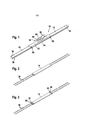
[0010] figura 1 vista em perspectiva de uma borracha de limpa- vidros de acordo com a invenção,[0010] figure 1 perspective view of a wiper rubber according to the invention,
[0011] figura 2 vista em perspectiva com duas varas molares com uma seção de suporte central,[0011] figure 2 perspective view with two molar rods with a central support section,
[0012] figura 3 vista em perspectiva de duas varas molares com a parte de suporte central e duas peças intermediárias,[0012] figure 3 perspective view of two molar rods with the central support part and two intermediate parts,
[0013] figura 4 vista em perspectiva de duas varas elásticas com três peças de suporte e duas peças intermediárias,[0013] figure 4 perspective view of two elastic rods with three support pieces and two intermediate pieces,
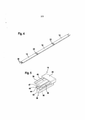
[0014] figura 5 uma extremidade de uma lâmina limpadora de acordo com a figura 1 em escala ampliada sem tampa terminal, e[0014] figure 5 an end of a cleaning blade according to figure 1 on an enlarged scale without end cap, and
[0015] figura 6 uma peça intermediária de acordo com a figura3, em escala ampliada,[0015] figure 6 an intermediate piece according to figure3, in an enlarged scale,
[0016] figura 7 uma variante relativamente à figura 5.[0016] figure 7 a variant with respect to figure 5.
[0017] Uma borracha de régua limpadora 10, de acordo com a figura 1 abrange um suporte com três componentes de suporte 12, 14, 16, duas tampas terminais 18, uma régua limpadora 38 e um elemento acoplador 50 para a união articulada com um braço limpador não mostrado mais detalhadamente. Entre a seção de suporte central 14 e as seções de suporte 12 e 16 acoplados na direção do exterior, estão previstas peças intermediárias 20.[0017] A cleaning strip rubber 10, according to figure 1, covers a support with three
[0018] Os componentes de suporte 12, 14, 16 e as peças intermediárias 20, bem como as tampas terminais 18, na sua seção transversal apresentam essencialmente o mesmo formato. Possuem uma parede de cobertura 26 na qual se ligam nos dois lados longitudinais paredes laterais 30. Em formato angular para o interior, nas arestas livres das paredes laterais 30 são perfilados trilhos retentores 32 que formam entre si uma fenda longitudinal 32. Nos lados longitudinais entre a parede de cobertura 26, as paredes laterais 30 e os trilhos retentores 28 estão previstos canais longitudinais 34. Os componentes de suporte 12, 14, 16 e as peças intermediárias 20 serão individualmente enfiados a partir das extremidades sobre o elemento de suporte, que podem ser configurados como varas elásticas 36 de seções transversais arredondadas ou como trilhos molares 64 de seções transversais re-tangulares. Finalmente, tampas terminais 18 são montadas nos elementos de suporte 36, 64 sendo com eles fixamente unidos por processo de colagem ou solda fraca, especialmente solda de ultrassom. Em caráter adicional, ao menos uma das peças intermediárias 20 pode ser fixamente unida com os elementos de suporte 36, 64. Outra possibilidade reside em que os componentes de suporte 12, 14, 16 e as pe-ças intermediárias 20 sejam unidas na seção frontal por solda, especialmente solda de ultrassom ou colagem, e as partes terminais 12, 16 seriam, por sua vez, unidas com as tampas terminais 18. Isto pode ocorrer quando os componentes 12, 14, 16, 18, 20 estiverem montados nos elementos de suporte 36, 64 ou até uma das tampas terminais 18 antes de serem montados nos elementos de suporte 36, 64.[0018] The
[0019] As tampas terminais 18 estão fechadas no seu lado frontal externo de maneira que as varas molares 36 estão protegidas em direção longitudinal. Inicialmente pode ser convenientemente unir firmemente ao menos umas das tampas terminais 18 e/ou um das peças intermediárias 20 com os elementos de suporte 36, 64.[0019] The
[0020] A seção transversal da régua limpadora 38 é constituída de forma convencional e aprovada. Um lábio limpador 40 cuneiforme está unido com a régua de topo 46 através de um filete basculante 42. Esta régua de topo 46 possui na direção do lábio limpador 40 a régua de suporte 44, na qual, por ocasião do movimento de limpeza, se apoia sempre uma das faces opostas do lábio limpador 40.[0020] The cross section of the
[0021] Para facilitar a montagem da régua limpadora 38, a régua limpadora 38 é produzida em um processo de moldagem por injeção de duas substâncias, empregando dois materiais diferentes, sendo o filete 48 entre as ranhuras longitudinais 47 e a parte da régua de topo 46 envolta pelos trilhos retentores 28, consistindo em material mais endurecido e rígido do que a parte restante da régua limpadora 38.[0021] To facilitate the assembly of the
[0022] O elemento acoplador 50 será unido articuladamente com o suporte 12, 14, 16, 18, 20. Para tanto, as peças intermediárias 20, no lado voltado da direção do elemento acoplador 50, possuem elementos articulados 22 que se salientam lateralmente além das paredes laterais 30 da peças intermediárias 20. Nessas unidades está articuladamente montada uma seção de ponte 52 por meio de cubos 56. Os cubos 56 encontram-se em castanhas 54 laterais com as quais a seção do ponto 52 envolvem lateralmente as peças intermediárias 20. Entre os elementos articulados 22, o componente de ponto 52 conforma um espaço livre para a seção de suporte 14, de maneira que a régua limpadora 38 pode se adaptar livremente a uma curvatura de um para-brisa do veículo. No caso, a força de compressão do braço limpador será vantajosamente transmitida sobre os elementos articulados 22 para a régua limpadora 38.[0022] The
[0023] No lado da seção da ponte 52, afastado em relação à régua limpadora 38, nesta seção de ponte 52 está preso o elemento acoplador 50. Ele pode ter uma forma de construção aleatória e conhecida, no presente caso, possui um fundo 60, o qual, de maneira adequada está unido por arrebites, soldadura, colagem, grampeamento ou semelhantes unidades com a seção da ponte 52. A partir do fundo 60 en- contram-se em formato angular duas seções laterais 58 que se projetam longitudinalmente e em sentido contrário ao lábio limpador 40. Os componentes laterais 58 possuem entre si, como elemento de montagem, um pino articulado 62, através do qual a borracha da limpa-vidros 10 pode ser articuladamente unida com o braço limpador não mostrado.[0023] On the side of the
Claims (6)
Applications Claiming Priority (3)
| Application Number | Priority Date | Filing Date | Title |
|---|---|---|---|
| DE102008002447.3 | 2008-06-16 | ||
| DE102008002447A DE102008002447A1 (en) | 2008-06-16 | 2008-06-16 | wiper blade |
| PCT/EP2009/055257 WO2009153097A1 (en) | 2008-06-16 | 2009-04-30 | Wiper blade |
Publications (2)
| Publication Number | Publication Date |
|---|---|
| BRPI0913608A2 BRPI0913608A2 (en) | 2015-11-24 |
| BRPI0913608B1 true BRPI0913608B1 (en) | 2020-08-11 |
Family
ID=40942421
Family Applications (1)
| Application Number | Title | Priority Date | Filing Date |
|---|---|---|---|
| BRPI0913608-8A BRPI0913608B1 (en) | 2008-06-16 | 2009-04-30 | GLASS CLEANER RUBBER |
Country Status (9)
| Country | Link |
|---|---|
| US (1) | US8839483B2 (en) |
| EP (1) | EP2291303B1 (en) |
| JP (1) | JP5265002B2 (en) |
| KR (1) | KR101598549B1 (en) |
| CN (1) | CN102066165B (en) |
| BR (1) | BRPI0913608B1 (en) |
| DE (1) | DE102008002447A1 (en) |
| RU (1) | RU2517927C2 (en) |
| WO (1) | WO2009153097A1 (en) |
Families Citing this family (24)
| Publication number | Priority date | Publication date | Assignee | Title |
|---|---|---|---|---|
| EP2660110B1 (en) * | 2010-12-27 | 2018-08-29 | Mitsuba Corporation | Wiper blade |
| CN103328279B (en) * | 2010-12-27 | 2015-09-16 | 株式会社美姿把 | Rain shaving blade and assemble the method for this rain shaving blade |
| US9457768B2 (en) | 2011-04-21 | 2016-10-04 | Pylon Manufacturing Corp. | Vortex damping wiper blade |
| US9174609B2 (en) | 2011-04-21 | 2015-11-03 | Pylon Manufacturing Corp. | Wiper blade with cover |
| MX345011B (en) | 2011-07-28 | 2017-01-11 | Pylon Mfg Corp | Windshield wiper adapter, connector and assembly. |
| US8806700B2 (en) | 2011-07-29 | 2014-08-19 | Pylon Manufacturing Corporation | Wiper blade connector |
| US9108595B2 (en) | 2011-07-29 | 2015-08-18 | Pylon Manufacturing Corporation | Windshield wiper connector |
| US10723322B2 (en) | 2012-02-24 | 2020-07-28 | Pylon Manufacturing Corp. | Wiper blade with cover |
| CA2865292C (en) | 2012-02-24 | 2018-03-13 | Pylon Manufacturing Corp. | Wiper blade |
| US20130219649A1 (en) | 2012-02-24 | 2013-08-29 | Pylon Manufacturing Corp. | Wiper blade |
| DE102012209304A1 (en) * | 2012-06-01 | 2013-12-05 | Robert Bosch Gmbh | Wiper blade device |
| US10829092B2 (en) | 2012-09-24 | 2020-11-10 | Pylon Manufacturing Corp. | Wiper blade with modular mounting base |
| US10166951B2 (en) | 2013-03-15 | 2019-01-01 | Pylon Manufacturing Corp. | Windshield wiper connector |
| US9505380B2 (en) | 2014-03-07 | 2016-11-29 | Pylon Manufacturing Corp. | Windshield wiper connector and assembly |
| USD777079S1 (en) | 2014-10-03 | 2017-01-24 | Pylon Manufacturing Corp. | Wiper blade frame |
| US10363905B2 (en) | 2015-10-26 | 2019-07-30 | Pylon Manufacturing Corp. | Wiper blade |
| CN109311451B (en) | 2016-05-19 | 2022-08-23 | 电缆塔制造有限公司 | Windscreen wiper blade |
| US11040705B2 (en) | 2016-05-19 | 2021-06-22 | Pylon Manufacturing Corp. | Windshield wiper connector |
| CN109715449A (en) | 2016-05-19 | 2019-05-03 | 电缆塔制造有限公司 | Windscreen wiper connector |
| CN109311452A (en) | 2016-05-19 | 2019-02-05 | 电缆塔制造有限公司 | Windscreen wiper connector |
| US10766462B2 (en) | 2016-05-19 | 2020-09-08 | Pylon Manufacturing Corporation | Windshield wiper connector |
| USD941737S1 (en) * | 2019-09-19 | 2022-01-25 | Robert Bosch Gmbh | Wiper blade |
| DE102021212633A1 (en) | 2021-11-10 | 2023-05-11 | Robert Bosch Gesellschaft mit beschränkter Haftung | Wiper blade and method of making the same |
| DE102021213233A1 (en) | 2021-11-24 | 2023-05-25 | Robert Bosch Gesellschaft mit beschränkter Haftung | Wiper blade and method of making same |
Family Cites Families (11)
| Publication number | Priority date | Publication date | Assignee | Title |
|---|---|---|---|---|
| US3116506A (en) * | 1961-01-16 | 1964-01-07 | Gen Motors Corp | Unitary squeegee and wiper blade assembly embodying the same |
| FR2705299B1 (en) * | 1993-05-17 | 1995-07-07 | Valeo Systemes Dessuyage | Two-piece coextruded wiper blade and wiper blade fitted with such a blade. |
| DE19801058A1 (en) | 1998-01-14 | 1999-07-15 | Bosch Gmbh Robert | Motor vehicle windscreen wiper blade with curved spring rail |
| DE19856300A1 (en) | 1998-12-07 | 2000-06-08 | Bosch Gmbh Robert | Wiper blade for windows of motor vehicles |
| DE10022724A1 (en) * | 2000-05-10 | 2001-11-22 | Bosch Gmbh Robert | Wiper strip for windscreen wiper; has shaped back section and functional part having support section connected to back section by first tilting link and wiper wedge connected by second tilting link |
| JPWO2004054859A1 (en) * | 2002-12-17 | 2006-04-20 | 株式会社ミツバ | Wiper blade |
| CN100389990C (en) * | 2003-03-07 | 2008-05-28 | 株式会社美姿把 | Wiper blade and method of producing the same |
| DE102004019158B4 (en) | 2004-04-21 | 2015-06-03 | Robert Bosch Gmbh | wiper blade |
| JP2007269170A (en) | 2006-03-31 | 2007-10-18 | Mitsuba Corp | Wiper blade |
| KR100753248B1 (en) * | 2006-08-10 | 2007-08-30 | 에이디엠이십일 주식회사 | Wiper blade |
| DE202006015206U1 (en) | 2006-10-05 | 2006-12-07 | Liao, Hsueh-Chih, Luzhou City | Windscreen wiper, comprises two integrated slightly curved steel wires keeping unit close to windscreen |
-
2008
- 2008-06-16 DE DE102008002447A patent/DE102008002447A1/en not_active Ceased
-
2009
- 2009-04-30 CN CN2009801223771A patent/CN102066165B/en active Active
- 2009-04-30 JP JP2011513965A patent/JP5265002B2/en not_active Expired - Fee Related
- 2009-04-30 US US12/999,429 patent/US8839483B2/en not_active Expired - Fee Related
- 2009-04-30 EP EP09765677A patent/EP2291303B1/en active Active
- 2009-04-30 KR KR1020107028222A patent/KR101598549B1/en active IP Right Grant
- 2009-04-30 WO PCT/EP2009/055257 patent/WO2009153097A1/en active Application Filing
- 2009-04-30 RU RU2011101498/11A patent/RU2517927C2/en active IP Right Revival
- 2009-04-30 BR BRPI0913608-8A patent/BRPI0913608B1/en not_active IP Right Cessation
Also Published As
| Publication number | Publication date |
|---|---|
| WO2009153097A1 (en) | 2009-12-23 |
| CN102066165B (en) | 2013-10-16 |
| EP2291303B1 (en) | 2012-10-24 |
| KR20110020254A (en) | 2011-03-02 |
| RU2011101498A (en) | 2012-08-10 |
| US8839483B2 (en) | 2014-09-23 |
| RU2517927C2 (en) | 2014-06-10 |
| BRPI0913608A2 (en) | 2015-11-24 |
| CN102066165A (en) | 2011-05-18 |
| EP2291303A1 (en) | 2011-03-09 |
| US20110247165A1 (en) | 2011-10-13 |
| JP5265002B2 (en) | 2013-08-14 |
| JP2011524302A (en) | 2011-09-01 |
| DE102008002447A1 (en) | 2009-12-17 |
| KR101598549B1 (en) | 2016-02-29 |
Similar Documents
| Publication | Publication Date | Title |
|---|---|---|
| BRPI0913608B1 (en) | GLASS CLEANER RUBBER | |
| ES2701435T3 (en) | Windshield wiper assembly | |
| ES2362305T3 (en) | WINDSHIELD ARM. | |
| ES2441180T3 (en) | Wiper blade | |
| US7503095B2 (en) | Non-bracket windshield wiper | |
| BRPI0819335B1 (en) | wiper blade | |
| ES2243507T3 (en) | WINDSHIELD WIPER BRUSH TO CLEAN VEHICLE WINDSHIELD. | |
| ES2337036T3 (en) | WINDSHIELD CLEANING DEVICE. | |
| RU2662603C2 (en) | Windscreen wiper device for vehicle | |
| US9434353B2 (en) | Flat wiper blade | |
| RU2002103314A (en) | Wiper Blade for Vehicles | |
| ES2403059T3 (en) | Connection device for the articulated connection of a wiper blade with a wiper arm | |
| ES2241351T3 (en) | DEVICE FOR THE ARTICULATED UNION OF A WINDSHIELD CLEANER SHEET FOR CAR CRYSTALS WITH A WINDSHIELD ARM. | |
| ES2376543T3 (en) | WINDSHIELD BRUSH. | |
| ES2203981T3 (en) | BRUSH FOR VEHICLE MOONS. | |
| ES2269918T3 (en) | WINDSHIELD CLEANING DEVICE. | |
| RU2002109235A (en) | Different sized wiper blades for vehicle windows | |
| BR112012011681B1 (en) | wiper blade in the form of a flat beam construction with a support element | |
| ES2860725T3 (en) | Vehicle body seal with trim molding | |
| BR0104485A (en) | Wiper Blade, especially of vehicles | |
| RU2001104886A (en) | WIPER BRUSH FOR VEHICLES | |
| ES2539049T3 (en) | Flat bar-shaped windshield wiper blade | |
| CA2818258C (en) | Beam blade wiper assembly having self-locking end cap | |
| KR100629161B1 (en) | Wiper blades for a car | |
| US20150113755A1 (en) | Longitudinal body for a vehicle window wiper |
Legal Events
| Date | Code | Title | Description |
|---|---|---|---|
| B06F | Objections, documents and/or translations needed after an examination request according [chapter 6.6 patent gazette] | ||
| B06T | Formal requirements before examination [chapter 6.20 patent gazette] | ||
| B09A | Decision: intention to grant [chapter 9.1 patent gazette] | ||
| B16A | Patent or certificate of addition of invention granted [chapter 16.1 patent gazette] |
Free format text: PRAZO DE VALIDADE: 10 (DEZ) ANOS CONTADOS A PARTIR DE 11/08/2020, OBSERVADAS AS CONDICOES LEGAIS. |
|
| B21F | Lapse acc. art. 78, item iv - on non-payment of the annual fees in time |
Free format text: REFERENTE A 13A ANUIDADE. |
|
| B24J | Lapse because of non-payment of annual fees (definitively: art 78 iv lpi, resolution 113/2013 art. 12) |
Free format text: EM VIRTUDE DA EXTINCAO PUBLICADA NA RPI 2668 DE 22-02-2022 E CONSIDERANDO AUSENCIA DE MANIFESTACAO DENTRO DOS PRAZOS LEGAIS, INFORMO QUE CABE SER MANTIDA A EXTINCAO DA PATENTE E SEUS CERTIFICADOS, CONFORME O DISPOSTO NO ARTIGO 12, DA RESOLUCAO 113/2013. |