BR112017012681B1 - Set of essentially identical floor panels - Google Patents
Set of essentially identical floor panels Download PDFInfo
- Publication number
- BR112017012681B1 BR112017012681B1 BR112017012681-8A BR112017012681A BR112017012681B1 BR 112017012681 B1 BR112017012681 B1 BR 112017012681B1 BR 112017012681 A BR112017012681 A BR 112017012681A BR 112017012681 B1 BR112017012681 B1 BR 112017012681B1
- Authority
- BR
- Brazil
- Prior art keywords
- locking
- edge
- groove
- strip
- panel
- Prior art date
Links
Images


Classifications
-
- B—PERFORMING OPERATIONS; TRANSPORTING
- B26—HAND CUTTING TOOLS; CUTTING; SEVERING
- B26D—CUTTING; DETAILS COMMON TO MACHINES FOR PERFORATING, PUNCHING, CUTTING-OUT, STAMPING-OUT OR SEVERING
- B26D3/00—Cutting work characterised by the nature of the cut made; Apparatus therefor
- B26D3/06—Grooving involving removal of material from the surface of the work
- B26D3/065—On sheet material
-
- E—FIXED CONSTRUCTIONS
- E04—BUILDING
- E04F—FINISHING WORK ON BUILDINGS, e.g. STAIRS, FLOORS
- E04F15/00—Flooring
- E04F15/02—Flooring or floor layers composed of a number of similar elements
- E04F15/02038—Flooring or floor layers composed of a number of similar elements characterised by tongue and groove connections between neighbouring flooring elements
-
- E—FIXED CONSTRUCTIONS
- E04—BUILDING
- E04C—STRUCTURAL ELEMENTS; BUILDING MATERIALS
- E04C2/00—Building elements of relatively thin form for the construction of parts of buildings, e.g. sheet materials, slabs, or panels
- E04C2/30—Building elements of relatively thin form for the construction of parts of buildings, e.g. sheet materials, slabs, or panels characterised by the shape or structure
- E04C2/40—Building elements of relatively thin form for the construction of parts of buildings, e.g. sheet materials, slabs, or panels characterised by the shape or structure composed of a number of smaller components rigidly or movably connected together, e.g. interlocking, hingedly connected of particular shape, e.g. not rectangular of variable shape or size, e.g. flexible or telescopic panels
-
- E—FIXED CONSTRUCTIONS
- E04—BUILDING
- E04F—FINISHING WORK ON BUILDINGS, e.g. STAIRS, FLOORS
- E04F15/00—Flooring
- E04F15/02—Flooring or floor layers composed of a number of similar elements
- E04F15/10—Flooring or floor layers composed of a number of similar elements of other materials, e.g. fibrous or chipped materials, organic plastics, magnesite tiles, hardboard, or with a top layer of other materials
- E04F15/102—Flooring or floor layers composed of a number of similar elements of other materials, e.g. fibrous or chipped materials, organic plastics, magnesite tiles, hardboard, or with a top layer of other materials of fibrous or chipped materials, e.g. bonded with synthetic resins
-
- E—FIXED CONSTRUCTIONS
- E04—BUILDING
- E04F—FINISHING WORK ON BUILDINGS, e.g. STAIRS, FLOORS
- E04F15/00—Flooring
- E04F15/02—Flooring or floor layers composed of a number of similar elements
- E04F15/10—Flooring or floor layers composed of a number of similar elements of other materials, e.g. fibrous or chipped materials, organic plastics, magnesite tiles, hardboard, or with a top layer of other materials
- E04F15/107—Flooring or floor layers composed of a number of similar elements of other materials, e.g. fibrous or chipped materials, organic plastics, magnesite tiles, hardboard, or with a top layer of other materials composed of several layers, e.g. sandwich panels
-
- E—FIXED CONSTRUCTIONS
- E04—BUILDING
- E04F—FINISHING WORK ON BUILDINGS, e.g. STAIRS, FLOORS
- E04F2201/00—Joining sheets or plates or panels
- E04F2201/01—Joining sheets, plates or panels with edges in abutting relationship
- E04F2201/0138—Joining sheets, plates or panels with edges in abutting relationship by moving the sheets, plates or panels perpendicular to the main plane
- E04F2201/0146—Joining sheets, plates or panels with edges in abutting relationship by moving the sheets, plates or panels perpendicular to the main plane with snap action of the edge connectors
-
- E—FIXED CONSTRUCTIONS
- E04—BUILDING
- E04F—FINISHING WORK ON BUILDINGS, e.g. STAIRS, FLOORS
- E04F2201/00—Joining sheets or plates or panels
- E04F2201/01—Joining sheets, plates or panels with edges in abutting relationship
- E04F2201/0153—Joining sheets, plates or panels with edges in abutting relationship by rotating the sheets, plates or panels around an axis which is parallel to the abutting edges, possibly combined with a sliding movement
- E04F2201/0161—Joining sheets, plates or panels with edges in abutting relationship by rotating the sheets, plates or panels around an axis which is parallel to the abutting edges, possibly combined with a sliding movement with snap action of the edge connectors
-
- E—FIXED CONSTRUCTIONS
- E04—BUILDING
- E04F—FINISHING WORK ON BUILDINGS, e.g. STAIRS, FLOORS
- E04F2201/00—Joining sheets or plates or panels
- E04F2201/01—Joining sheets, plates or panels with edges in abutting relationship
- E04F2201/0169—Joining sheets, plates or panels with edges in abutting relationship by rotating the sheets, plates or panels around an axis which is perpendicular to the abutting edges and parallel to the main plane, possibly combined with a sliding movement
- E04F2201/0176—Joining sheets, plates or panels with edges in abutting relationship by rotating the sheets, plates or panels around an axis which is perpendicular to the abutting edges and parallel to the main plane, possibly combined with a sliding movement with snap action of the edge connectors
-
- E—FIXED CONSTRUCTIONS
- E04—BUILDING
- E04F—FINISHING WORK ON BUILDINGS, e.g. STAIRS, FLOORS
- E04F2201/00—Joining sheets or plates or panels
- E04F2201/02—Non-undercut connections, e.g. tongue and groove connections
- E04F2201/027—Non-undercut connections, e.g. tongue and groove connections connected by tongues and grooves, the centerline of the connection being inclined to the top surface
-
- E—FIXED CONSTRUCTIONS
- E04—BUILDING
- E04F—FINISHING WORK ON BUILDINGS, e.g. STAIRS, FLOORS
- E04F2201/00—Joining sheets or plates or panels
- E04F2201/04—Other details of tongues or grooves
- E04F2201/042—Other details of tongues or grooves with grooves positioned on the rear-side of the panel
-
- E—FIXED CONSTRUCTIONS
- E04—BUILDING
- E04F—FINISHING WORK ON BUILDINGS, e.g. STAIRS, FLOORS
- E04F2201/00—Joining sheets or plates or panels
- E04F2201/04—Other details of tongues or grooves
- E04F2201/043—Other details of tongues or grooves with tongues and grooves being formed by projecting or recessed parts of the panel layers
Landscapes
- Engineering & Computer Science (AREA)
- Architecture (AREA)
- Civil Engineering (AREA)
- Structural Engineering (AREA)
- Life Sciences & Earth Sciences (AREA)
- Forests & Forestry (AREA)
- Mechanical Engineering (AREA)
- Floor Finish (AREA)
- Joining Of Building Structures In Genera (AREA)
Abstract
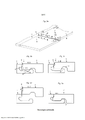
CONJUNTO DE PAINÉIS DE CHÃO ESSENCIALMENTE IDÊNTICOS. A presente invenção refere-se a painéis de chão (1, 1'), os quais são providos com um sistema de travamento mecânico que pode ser travado por meio do deslocamento vertical de um primeiro painel contra o segundo painel. O sistema de travamento compreende uma borda flexível (6) que, durante o travamento, se dobra para cima ou para baixo. O sistema de travamento compreende uma primeira (7a) e uma segunda (7b) seção da borda de junção com diferentes funções de travamento. Uma seção provê um travamento horizontal e outra seção provê um travamento vertical.ESSENTIALLY IDENTICAL FLOOR PANELS SET. The present invention relates to floor panels (1, 1'), which are provided with a mechanical locking system that can be locked by vertical displacement of a first panel against the second panel. The locking system comprises a flexible edge (6) which, during locking, bends up or down. The locking system comprises a first (7a) and a second (7b) joint edge section with different locking functions. One section provides a horizontal lock and another section provides a vertical lock.
Description
[0001] A presente invenção refere-se, em geral, ao campo dos sistemas de travamento mecânico para painéis de chão e painéis de construção. A presente descrição inclui painéis, assoalhos, sistemas de travamento e métodos de produção.[0001] The present invention generally relates to the field of mechanical locking systems for floor panels and building panels. The present description includes panels, floors, locking systems and production methods.
[0002] As modalidades da presente invenção são particularmente adequadas para uso em pisos oscilantes, os quais são formados por painéis de chão contendo uma ou mais camadas superiores que compreendem, por exemplo, termoplástico ou material termoendurecível ou folheado de madeira, um núcleo intermediário feito de material à base de fibra de madeira ou material plástico e, de maneira preferida, uma camada estabilizadora inferior localizada no lado traseiro do núcleo. As modalidades da invenção também podem ser usadas para unir painéis de construção, os quais, de maneira preferida, contêm um material de placa, por exemplo, painéis de parede, tetos, componentes de mobília e similares.[0002] Embodiments of the present invention are particularly suitable for use in swing floors, which are formed by floor panels containing one or more top layers comprising, for example, thermoplastic or thermosetting material or wood veneer, an intermediate core made of material based on wood fiber or plastic material and preferably a lower stabilizing layer located on the rear side of the core. Embodiments of the invention can also be used to join building panels which preferably contain a board material, for example wall panels, ceilings, furniture components and the like.
[0003] A descrição a seguir sobre a técnica anterior, os problemas de sistemas, objetivos e características conhecidas da invenção terá como objetivo, na forma de um exemplo não restritivo, acima de tudo este campo de aplicação e, em particular, os pisos laminados que compreendem um núcleo de HDF e que são formados como painéis de chão retangulares com bordas longas e curtas, destinados a serem mecanicamente unidos uns aos outros pelas bordas longas e curtas.[0003] The following description of the prior art, the problems of systems, objectives and known characteristics of the invention will aim, in the form of a non-restrictive example, above all this field of application and, in particular, laminate floors which comprise an HDF core and which are formed as rectangular floor panels with long and short edges, intended to be mechanically joined together by the long and short edges.
[0004] Os termos bordas longas e curtas são usados principalmente para simplificar a descrição da invenção. Os painéis podem ser quadrados. Os painéis de chão, são geralmente produzidos com uma camada de superfície virada para baixo de modo a eliminar as folgas de espessura do material de núcleo. Algumas modalidades e métodos de produção são mostrados com a superfície virada para cima para simplificar sua descrição.[0004] The terms long and short edges are used primarily to simplify the description of the invention. Panels can be square. Floor panels are generally produced with a surface layer facing downwards to eliminate gaps in the thickness of the core material. Some production modalities and methods are shown with the surface facing up to simplify their description.
[0005] É válido enfatizar que as modalidades da invenção podem ser usadas em qualquer painel de chão com bordas longas e/ou curtas, e que esse painel pode ser combinado com todos os tipos de sistemas de travamento conhecidos em bordas longas ou bordas curtas que travam os painéis na direção horizontal e/ou vertical.[0005] It is worth emphasizing that the embodiments of the invention can be used on any floor panel with long and/or short edges, and that this panel can be combined with all types of known locking systems on long edges or short edges that lock the panels in the horizontal and/or vertical direction.
[0006] As partes relevantes desta descrição de antecedentes também fazem parte das modalidades da invenção apresentada.[0006] The relevant parts of this background description also form part of the embodiments of the present invention.
[0007] Vários painéis de chão disponíveis no mercado são instalados de um modo oscilante com sistemas de travamento mecânico formados nas bordas longas e curtas. Esses sistemas compreendem meios de travamento, os quais travam os painéis horizontalmente e verticalmente. Os sistemas de travamento mecânico são geralmente formados por meio da maquinagem do núcleo do painel. De maneira alternativa, partes do sistema de travamento podem ser formadas por um material separado, por exemplo, material feito de alumínio ou plástico, o qual é integrado ao painel de chão, ou seja, ligado ao painel de chão durante a fabricação do mesmo.[0007] Several floor panels available on the market are installed in an oscillating fashion with mechanical locking systems formed on the long and short edges. These systems comprise locking means which lock the panels horizontally and vertically. Mechanical locking systems are generally formed by machining the panel core. Alternatively, parts of the locking system may be formed of a separate material, for example material made of aluminum or plastic, which is integrated into the floor panel, i.e. bonded to the floor panel during manufacture thereof.
[0008] O pavimento de laminado geralmente compreende um núcleo à base de madeira de 6-8 mm, uma camada de superfície decorativa superior do laminado com 0,2 mm de espessura e uma camada estabilizadora inferior com 0,1 mm de espessura. A superfície do laminado e a camada estabilizadora compreendem papel impregnado de melamina. O material de núcleo mais comum é o painel de fibra com alta densidade e boa estabilidade geralmente chamado de HDF - Painel de fibra de Alta Densidade. A superfície impregnada e os papéis estabilizadores são aderidos por meio de laminação ao núcleo com aplicação de calor e pressão. O material HDF é rígido e possui uma baixa flexibilidade, especialmente na direção vertical perpendicular à orientação da fibra.[0008] Laminate flooring generally comprises a 6-8 mm wood-based core, a 0.2 mm thick upper decorative surface layer of the laminate and a 0.1 mm thick lower stabilizing layer. The laminate surface and stabilizing layer comprise melamine impregnated paper. The most common core material is fiberboard with high density and good stability commonly called HDF - High Density Fiberboard. The impregnated surface and stabilizing papers are adhered by lamination to the core with the application of heat and pressure. HDF material is rigid and has low flexibility, especially in the vertical direction perpendicular to the fiber orientation.
[0009] Recentemente, um novo tipo de piso laminado à base de pó tem sido introduzido no mercado. Nesse caso, o papel impregnado é substituído por uma mistura de pó seco que compreende fibras de madeira, partículas de melamina, óxido de alumínio e pigmentos. O pó é aplicado a um núcleo de HDF e curado sob calor e pressão. Geralmente, um HDF de alta qualidade é usado com um grande teor de resina e baixa retenção de água. Tipos avançados de decoração podem ser criados por impressão digital. Uma tinta à base de água é injetada no pó antes da prensagem.[0009] Recently, a new type of powder-based laminate flooring has been introduced in the market. In this case, the impregnated paper is replaced by a dry powder mixture comprising wood fibers, melamine particles, aluminum oxide and pigments. The powder is applied to an HDF core and cured under heat and pressure. Generally, a high quality HDF is used with a high resin content and low water retention. Advanced types of decoration can be created by digital printing. A water-based ink is injected into the powder before pressing.
[00010] O piso vinílico de luxo, LVT, piso com uma espessura de 3 - 6 mm, geralmente compreende uma camada de desgaste transparente, a qual pode ser revestida com um raio ultravioleta (UV), poliuretano curado (PU), laca e uma folha de plástico decorativa por baixo da folha transparente. A camada de desgaste e a folha decorativa são laminadadas em uma ou várias camadas do núcleo que compreendem uma mistura de material termoplástico e materiais de enchimento minerais. O núcleo de plástico pode ser muito macio e flexível, mas também muito rígido dependendo do teor de material de enchimento.[00010] Luxury vinyl flooring, LVT, flooring with a thickness of 3 - 6 mm, generally comprises a transparent wear layer, which can be coated with an ultraviolet ray (UV), cured polyurethane (PU), lacquer and a decorative plastic sheet under the clear sheet. The wear layer and the decorative sheet are laminated to one or more core layers comprising a mixture of thermoplastic material and mineral fillers. The plastic core can be very soft and flexible, but also very rigid depending on the filler content.
[00011] Pisos compostos de madeira e pástico, geralmente referidos como pisos WPC, são similares aos pisos LVT. O núcleo compreende um material termoendurecível misturado com materiais de enchimento de fibra de madeira e é geralmente mais resistente e muito mais rígido do que o núcleo de LVT à base de mineral.[00011] Wood and plastic composite floors, commonly referred to as WPC floors, are similar to LVT floors. The core comprises a thermosetting material blended with wood fiber filler materials and is generally stronger and much stiffer than mineral-based LVT core.
[00012] Materiais termoplásticos, tais como PVC, PP ou PE, podem ser combinados com uma mistura de fibras de madeira e partículas minerais e essa pode prover uma ampla variedade de painéis de chão com diferentes densidades e flexibilidades.[00012] Thermoplastic materials such as PVC, PP or PE can be combined with a mixture of wood fibers and mineral particles and this can provide a wide variety of floor panels with different densities and flexibilities.
[00013] HDF resistente à humidade com um alto teor de resina e pisos WPC compreendem materiais de núcleo mais resistentes e mais flexíveis do que os pisos laminados à base de HDF convencionais e são geralmente produzidos com uma espessura menor.[00013] Moisture resistant HDF with a high resin content and WPC floors comprise stronger and more flexible core materials than conventional HDF-based laminate floors and are generally produced in a thinner thickness.
[00014] Os tipos de piso mencionados acima compreendem diferentes materiais de núcleo com diferente flexibilidade, densidade e resistências. Os sistemas de travamento formados de maneira integral com o núcleo devem ser adaptados para essas propriedades de material diferentes de modo a prover uma função de travamento potente e econômica.[00014] The types of flooring mentioned above comprise different core materials with different flexibility, density and strengths. Locking systems formed integrally with the core must be adapted to these different material properties in order to provide a powerful and cost-effective locking function.
[00015] No texto, a superfície visível do painel de chão instalado é chamada de "lado frontal" ou "superfície do piso", enquanto o lado oposto do painel de chão, que faceia o subpiso, é chamado de "lado traseiro". A borda entre o lado frontal e lado traseiro é chamada de "borda de junção". Por "plano horizontal" entende-se um plano que se estende paralelo a oo lado frontal. As partes superiores imediatamente justapostas de duas bordas adjacentes de junção de dois painéis de chão unidos um ao outro definem um "plano vertical" perpendicular ao plano horizontal. Por "travamento vertical" entende-se o travamento paralelo ao plano vertical. Por "travamento horizontal" entende-se o travamento paralelo ao plano horizontal.[00015] In the text, the visible surface of the installed floor panel is called the "front side" or "floor surface", while the opposite side of the floor panel, which faces the subfloor, is called the "rear side". The edge between the front side and back side is called the "joint edge". By "horizontal plane" is meant a plane that extends parallel to the front side. The immediately juxtaposed upper parts of two adjacent joining edges of two floor panels joined together define a "vertical plane" perpendicular to the horizontal plane. By "vertical locking" is meant locking parallel to the vertical plane. By "horizontal locking" is meant locking parallel to the horizontal plane.
[00016] Por "em cima" entende-se em direção ao lado frontal, por "embaixo" em direção ao lado traseiro, por "para dentro" entende-se, sobretudo, horizontalmente em direção a uma parte interna e central do painel e por "para fora" entende-se, sobretudo, horizontalmente longe da parte central do painel.[00016] By "above" is meant towards the front side, by "below" towards the rear side, by "inside" is meant, above all, horizontally towards an inner and central part of the panel and by "outward" is meant, above all, horizontally away from the central part of the panel.
[00017] Por superfície ou parede "essencialmente vertical" entende- se uma superfície ou uma parede com inclinação menor que 45 graus em relação a um plano vertical.[00017] By "essentially vertical" surface or wall is meant a surface or wall inclined less than 45 degrees from a vertical plane.
[00018] Por superfície "essencialmente horizontal" entende-se uma superfície com inclinação menor que 45 graus em relação um plano horizontal.[00018] An "essentially horizontal" surface means a surface with an inclination of less than 45 degrees in relation to a horizontal plane.
[00019] Por ângulo de travamento de painéis de travamento de uma superfície na direção horizontal entende-se o ângulo da superfície relativo ao plano vertical.[00019] By locking angle of locking panels of a surface in the horizontal direction is meant the angle of the surface relative to the vertical plane.
[00020] Por ângulo de travamento de painéis de travamento de uma superfície na direção vertical entende-se o ângulo da superfície relativo ao plano horizontal.[00020] By locking angle of locking panels of a surface in the vertical direction is meant the angle of the surface relative to the horizontal plane.
[00021] Uma linha tangente define a inclinação de uma parede ou superfície curvada. Técnica Relacionada e Problemas da Mesma[00021] A tangent line defines the slope of a curved wall or surface. Related Technique and Problems with It
[00022] Para a junção mecânica das bordas longas, bem como das bordas curtas na direção vertical e na direção horizontal perpendicular às bordas, vários métodos podem ser usados. Um dos métodos mais usados é o método "angle-snap" (ajuste/resolução angular. As bordas longas são instaladas por meio de angulagem. "Snapping") horizontal trava as bordas curtas. A conexão vertical, é geralmente uma lingueta e uma ranhura e a conexão horizontal é uma tira com um elemento de travamento em uma borda que coopera com uma ranhura de travamento na borda adjacente. O travamento por "snapping" é obtido com uma borda flexível que, durante o estágio inicial de travamento, se dobra para baixo e, durante o estágio final de travamento, se dobra para cima para que o elemento de travamento seja inserido na ranhura de travamento.[00022] For mechanical joining of the long edges as well as the short edges in the vertical direction and in the horizontal direction perpendicular to the edges, various methods can be used. One of the most commonly used methods is the "angle-snap" method. The vertical connection is generally a tongue and groove and the horizontal connection is a strip with a locking element on one edge that cooperates with a locking groove on the adjacent edge. Snapping locking is achieved with a flexible edge that, during the initial locking stage, bends downwards and, during the final locking stage, bends upwards so that the locking element is inserted into the locking groove. .
[00023] Sistemas de travamento similares também podem ser produzidos com uma tira rígida e ser conectados por meio de um método angulagem por angulagem, no qual tanto as bordas curtas quanto as longas são anguladas em direção à posição travada.[00023] Similar locking systems can also be produced with a rigid strip and be connected via an angling-by-angling method, in which both the short and long edges are angled towards the locked position.
[00024] Os assim chamados "sistemas avançados de travamento dobrados" com uma lingueta separada e flexível em uma borda curta, geralmente chamados de "sistemas5G", têm sido introduzidos no mercado, por meio dos quais tanto as bordas longas quanto as curtas são travadas por uma ação de angulagem. Um painel de chão desse tipo é apresentado no WO 2006/043893. O qual descreve um painel de chão com um sistema de travamento com borda curta compreendendo um elemento de travamento que coopera com uma ranhura de travamento para o travamento horizontal e uma assim chamada "lingueta do tipo banana" flexível e em forma de arco que coopera com a ranhura da lingueta para travar em uma direção vertical. Uma lingueta flexível e em forma de arco é inserida, durante a produção, dentro de uma ranhura de deslocamento formada na borda. A lingueta dobra-se horizontalmente ao longo da borda durante a conexão e torna possível a instalação dos painéis por meio de um movimento vertical. As bordas longas são conectadas por angulagem e um movimento vertical do tipo tesoura causado pela mesma ação de angulagem que conecta as bordas curtas. A resistência ao "snapping" é baixa e apenas um pouco de pressão do polegar é necessária para comprimir as bordas curtas durante o estágio final da angulagem. Tal travamento é geralmente referido como "dobra vertical".[00024] So-called "advanced bent locking systems" with a separate flexible tongue on a short edge, often referred to as "5G systems", have been introduced to the market, whereby both long and short edges are locked by an angling action. Such a floor panel is disclosed in WO 2006/043893. Which describes a floor panel with a short edge locking system comprising a locking element that cooperates with a locking groove for horizontal locking and a so-called flexible, arc-shaped "banana-type tongue" that cooperates with the tongue groove to lock in a vertical direction. A flexible, arc-shaped tongue is inserted, during production, into an offset groove formed in the edge. The tongue bends horizontally along the edge during connection and makes it possible to install the panels by means of a vertical movement. The long edges are connected by angling and a vertical scissor-like motion caused by the same angling action that connects the short edges. Resistance to snapping is low and only a little thumb pressure is needed to compress the short edges during the final stage of angling. Such locking is generally referred to as a "vertical bend".
[00025] Painéis de chão similares também são descritos no WO 2007/015669. A presente invenção provê um sistema de travamento por dobra com uma lingueta flexível aprimorada assim chamada de "lingueta do tipo filamento" que compreende uma borda de lingueta externa e reta ao longo de praticamente todo o comprimento da lingueta. Uma parte interna da lingueta compreende protuberâncias dobráveis que se estendem horizontalmente ao longo do corpo da lingueta.[00025] Similar floor panels are also described in WO 2007/015669. The present invention provides a bend locking system with an improved flexible tongue so-called "filament type tongue" which comprises a straight outer tongue edge along substantially the entire length of the tongue. An inner part of the tongue comprises bendable protuberances that extend horizontally along the body of the tongue.
[00026] O "sistema 5G" dobrado mencionado acima tem sido muito eficiente e ganhou a maior parcela do mercado premium mundial de pisos de laminado e madeira. Seu travamento é forte e confiável, principalmente devido à flexibilidade e pré-tensionamento da lingueta flexível separada que permite um travamento com grande sobreposição das superfícies de travamento essencialmente horizontais.[00026] The folded "5G system" mentioned above has been very efficient and has gained the largest share of the premium laminate and hardwood flooring world market. Its locking is strong and reliable, mainly due to the flexibility and pre-tensioning of the separate flexible pawl that allows locking with large overlap of the essentially horizontal locking surfaces.
[00027] O sistema 5G e sistemas similares têm sido menos eficientes nos segmentos de mercado de baixo preço. A principal razão para tanto é que o custo das linguetas separadas e os investmentos em equipamento especial de inserção, que é necessário para inserir uma lingueta flexível em uma ranhura de deslocamento, são considerados muito altos em comparação com o preço muito baixo dos painéis de chão.[00027] The 5G system and similar systems have been less efficient in the low-price market segments. The main reason for this is that the cost of separate tongues and the investments in special insertion equipment, which is required to insert a flexible tongue into an offset slot, are considered to be very high compared to the very low price of floor panels. .
[00028] Várias tentativas foram feitas para prover um sistema de travamento por dobra, baseado em uma função de "snapping" vertical, o qual pode ser produzido em uma peça com o núcleo, do mesmo modo que os sistemas de "snapping" horizontal. Todas essas tentativas fracassaram, especialmente no caso de um painel de chão com núcleo de HDF, o que não é uma coincidência. A falha ocorreu devido a problemas graves relacionados às propriedades do material e aos métodos de produção. Vários dos sistemas de travamento conhecidos se baseiam em geometrias e modelos teóricos que não foram testados em aplicações industriais. Uma das principais razões por trás da falha, é que a flexão das partes verticalmente projetadas usadas para o travamento vertical das bordas está limitada a cerca de 50% da espessura do piso ou a cerca de 4 mm em um painel de chão laminado com 8 mm de espessura. É válido mencionar uma comparação na qual uma tira protuberante usada para um aperto horizontal pode se estender por uma distância substancial a partir da borda superior e pode se projetar por 8 - 10 mm para além da borda superior. Isso pode ser usado para facilitar uma flexão descendente da tira e do elemento de travamento. Outras desvantagens relacionadas ao "snapping" horizontal são que o HDF compreende uma orientação de fibra substancialmente paralela à superfície do piso. As propriedades do material são definidas para que a flexão das partes horizontalmente projetadas seja mais fácil de se obter do que a flexão das partes verticalmente projetadas. Além disso, as partes inferiores de um painel de HDF compreendem uma densidade mais alta e um teor de resina mais alto do que as partes medianas, e tais propriedades também são favoráveis para os sistemas de aperto horizontal, nos quais a tira é formada na parte inferior do núcleo.[00028] Several attempts have been made to provide a bend locking system, based on a vertical snapping function, which can be produced in a core part, in the same way as horizontal snapping systems. All these attempts have failed, especially in the case of an HDF-core floor panel, which is not a coincidence. The failure occurred due to serious issues related to material properties and production methods. Many of the known locking systems are based on theoretical geometries and models that have not been tested in industrial applications. One of the main reasons behind the failure is that the bending of the vertically projecting parts used for the vertical locking of the edges is limited to about 50% of the floor thickness or about 4mm in an 8mm laminated floor panel. of thickness. It is worth mentioning a comparison in which a protruding strip used for a horizontal grip can extend a substantial distance from the top edge and can protrude 8 - 10 mm beyond the top edge. This can be used to facilitate downward bending of the strap and locking element. Other disadvantages related to horizontal snapping are that HDF comprises a fiber orientation substantially parallel to the floor surface. The material properties are defined so that bending horizontally projecting parts is easier to achieve than bending vertically projecting parts. Furthermore, the lower parts of an HDF panel comprise a higher density and a higher resin content than the middle parts, and such properties are also favorable for horizontal clamping systems, in which the strip is formed on the part. bottom of the core.
[00029] Outra circunstância que suportou a introdução dos sistemas de "snap" horizontal no mercado é o fato de que um martelo e um bloco de fixação podem ser usados para comprimir as bordas curtas. Sistemas por dobra são assim chamados de sistemas com menos ferramentas, nos quais o travamento vertical é efetuado apenas pela pressão da mão.[00029] Another circumstance that supported the introduction of horizontal snap systems on the market is the fact that a hammer and clamping block can be used to compress the short edges. Bending systems are so-called systems with fewer tools, in which vertical locking is effected only by hand pressure.
[00030] Seria ainda mais vantajoso, se um sistema de travamento por dobra de peça única pudesse ser formado com a qualidade e a função de travamento similar aos sistemas 5G avançados.[00030] It would be even more advantageous if a one-piece bend locking system could be formed with the quality and locking function similar to advanced 5G systems.
[00031] Um objetivo das modalidades da presente invenção é a provisão de um sistema de travamento por dobra aprimorado e mais econômico para o travamento vertical e horizontal de painéis adjacentes, no qual o sistema de travamento é produzido integralmente com o núcleo.[00031] An object of embodiments of the present invention is the provision of an improved and more economical bend locking system for vertical and horizontal locking of adjacent panels, in which the locking system is produced integrally with the core.
[00032] Um primeiro objetivo específico é a provisão de um sistema de travamento no qual uma borda flexível horizontalmente estendida pode ser usada para efetuar o travamento vertical e horizontal.[00032] A first specific objective is the provision of a locking system in which a horizontally extending flexible edge can be used to effect both vertical and horizontal locking.
[00033] Um segundo objetivo específico é a provisão de um sistema de travamento com superfícies de travamento que se estendem de modo essencialmente horizontal para o travamento vertical, de maneira que uma força de travamento intesa posa ser obtida na direção vertical.[00033] A second specific objective is the provision of a locking system with locking surfaces that extend essentially horizontally for vertical locking, so that an intense locking force can be obtained in the vertical direction.
[00034] Um terceiro objetivo específico é a prevenção das forças de separação entre as bordas durante o travamento e a diminuição da resistência ao "snapping" para que uma instalação com menos ferramentas possa ser obtida e com menos pressão sendo aplicada às bordas curtas.[00034] A third specific objective is the prevention of separation forces between edges during locking and the decrease of snapping resistance so that a less tooled installation can be achieved and with less pressure being applied to the short edges.
[00035] Um quarto objetivo específico é a provisão de um método econômico para formar elementos de travamento em um perfilador de ponta dupla compreendendo uma corrente inferior e uma correia superior que deslocam o painel em relação a várias estações de ferramenta.[00035] A fourth specific objective is the provision of an economical method for forming locking elements in a double-ended profiler comprising a lower chain and an upper belt which displace the panel in relation to various tool stations.
[00036] Os objetivos da invenção mencionados acima podem ser atingidos pelas modalidades da invenção.[00036] The objects of the invention mentioned above can be achieved by the embodiments of the invention.
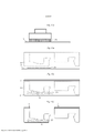
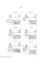
[00037] De acordo com um primeiro aspecto da invenção, um conjunto de painéis de chão essencialmente idênticos são providos com um sistema de travamento mecânico compreendendo uma tira que se estende horizontalmente a partir de uma parte inferior de uma primeira borda e uma ranhura de travamento que se abre para baixo e é formada em uma segunda borda adjacente. A tira compreende um elemento de travamento projetado para cima que está configurado para cooperar com a ranhura de travamento e travar a primeira e segunda borda em uma direção horizontal paralela ao plano principal dos primeiro e segundo painéis e em uma direção vertical perpendicular à direção horizontal. O sistema de travamento está configurado para ser travado por meio do deslocamento vertical da segunda borda contra a primeira borda na qual a tira, de maneira preferida, uma porção externa da tira, durante um estágio inicial do deslocamento vertical, é configurada para dobrar-se para cima em direção ao segundo painel e, durante um estágio final, do deslocamento vertical é configurada para dobrar-se para baixo em direção à sua posição inicial não travada.[00037] According to a first aspect of the invention, a set of essentially identical floor panels are provided with a mechanical locking system comprising a strip extending horizontally from a lower part of a first edge and a locking groove. which opens downwards and is formed on a second adjacent edge. The strip comprises an upwardly projecting locking element which is configured to cooperate with the locking groove and lock the first and second edges in a horizontal direction parallel to the principal plane of the first and second panels and in a vertical direction perpendicular to the horizontal direction. The locking system is configured to be locked by vertical displacement of the second edge against the first edge in which the strip, preferably an outer portion of the strip, during an initial stage of the vertical displacement, is configured to bend. upwards towards the second panel and, during a final stage, the vertical offset is set to fold downwards towards its unlatched home position.
[00038] Uma porção superior do elemento de travamento pode ser configurada para ser deslocada, durante o travamento, para dentro de um espaço provido entre uma parede da ranhura externa de travamento e uma superfície interna do elemento de travamento. O deslocamento pode ser causado por pelo menos uma ação dentre flexão, compressão e torção da tira. De maneira opcional, a porção superior do elemento de travamento pode ser, durante o travamento, adicionalmente configurada para ser deslocada para fora do espaço.[00038] An upper portion of the locking member may be configured to be displaced, during locking, into a space provided between an outer locking groove wall and an inner surface of the locking member. Displacement can be caused by at least one action of bending, compressing and twisting the strip. Optionally, the upper portion of the locking element can be, during locking, further configured to be moved out of space.
[00039] A flexão pode compreender rotação e/ou um deslocamento pelo menos de partes da tira.[00039] Bending may comprise rotation and/or a displacement of at least parts of the strip.
[00040] De acordo com uma modalidade, o espaço entre a parede da ranhura externa e a superfície interna é uma cavidade localizada na superfície interna do elemento de travamento. De acordo com outra modalidade, o espaço é uma cavidade localizada na parede da ranhura externa de travamento. De acordo com outra modalidade, o espaço é uma cavidade localizada parcialmente na superfície interna e uma cavidade localizada parcialmente na parede da ranhura externa.[00040] According to one embodiment, the space between the outer groove wall and the inner surface is a cavity located on the inner surface of the locking element. According to another embodiment, the space is a cavity located in the wall of the external locking groove. According to another embodiment, the space is a cavity located partially on the inner surface and a cavity located partially on the wall of the outer groove.
[00041] A tira pode ser configurada para dobrar-se para cima em direção à porção de um lado frontal do segundo painel. A porção pode ser uma porção externa do lado frontal.[00041] The strip can be configured to fold up towards the portion of a front side of the second panel. The portion may be an outer portion of the front side.
[00042] De maneira opcional, a flexão para cima e/ou para baixo da tira pode ser combinada com pelo menos uma ação dentre torção ou compressão da tira.[00042] Optionally, the upward and/or downward bending of the strip can be combined with at least one action of twisting or compressing the strip.
[00043] A tira pode ser configurada para dobrar-se para cima a partir da posição não travada para uma posição final. Além disso, a tira pode ser configurada para dobrar-se para baixo a partir da posição final e pelo menos parcialmente de volta para a posição não travada. Em um exemplo não limitante, uma porção externa e inferior da tira é deslocada verticalmente para cima a partir da posição não travada para a posição final por uma primeira distância e em seguida, é deslocada verticalmente para baixo por uma segunda distância, na qual a segunda distância está entre 10% e 95% da primeira distância, por exemplo, 40% ou 50%. Em outro exemplo não limitante, a tira dobra-se completamente de volta para a posição correspondente à posição não travada para que a segunda distância seja essencialmente a mesma que a primeira distância.[00043] The strip can be configured to fold up from the unlatched position to an end position. Furthermore, the strip can be configured to fold down from the end position and at least partially back to the unlatched position. In a non-limiting example, an outer and lower portion of the strip is shifted vertically upwards from the unlatched position to the end position by a first distance and then is shifted vertically downwards by a second distance, in which the second distance is between 10% and 95% of the first distance, for example 40% or 50%. In another non-limiting example, the strip folds completely back into the position corresponding to the unlatched position so that the second distance is essentially the same as the first distance.
[00044] Os primeiro e segundo painéis podem compreender um par de bordas curtas paralelas e um par de bordas longas paralelas, de modo que as bordas longas sejam perpendiculares às bordas curtas. As primeira e segunda bordas podem ser bordas curtas.[00044] The first and second panels may comprise a pair of parallel short edges and a pair of parallel long edges, so that the long edges are perpendicular to the short edges. The first and second edges can be short edges.
[00045] O plano principal dos primeiro e segundo painéis pode ser um plano horizontal, essencialmente paralelo com o lado frontal e/ou o lado traseiro do primeiro e/ou o segundo painel.[00045] The main plane of the first and second panels may be a horizontal plane, essentially parallel with the front side and/or the rear side of the first and/or the second panel.
[00046] Por um deslocamento vertical, entende-se que as bordas dos painéis são deslocadas uma contra a outra, pelo menos em uma direção vertical. De maneira opcional, no entanto, o deslocamento vertical também pode ser combinado com uma ação de angulagem. De acordo com uma modalidade, o deslocamento vertical é um movimento de tesoura vertical causado pela mesma ação de angulagem que é usada para conectar as bordas dos painéis que são perpendiculares às primeira e segunda bordas. Por exemplo, as primeira e segunda bordas podem ser bordas curtas e as bordas perpendiculares podem ser bordas longas. De acordo com outra modalidade, os lados frontais dos primeiro e segundo painéis estão essencialmente paralelos um ao outro durante o deslocamento vertical.[00046] By a vertical offset, it is meant that the edges of the panels are offset against each other, at least in a vertical direction. Optionally, however, vertical displacement can also be combined with a angling action. In one embodiment, vertical displacement is a vertical scissor motion caused by the same angling action that is used to connect edges of panels that are perpendicular to the first and second edges. For example, the first and second edges can be short edges and the perpendicular edges can be long edges. According to another embodiment, the front sides of the first and second panels are essentially parallel to each other during vertical displacement.
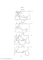
[00047] As primeira e segunda bordas podem compreender uma primeira seção de borda e uma segunda seção de borda ao longo das primeira e segunda bordas, de modo que uma seção transversal da ranhura de travamento ou uma seção transversal do elemento de travamento varie ao longo da primeira borda e/ou da segunda borda, na posição travada.[00047] The first and second edges may comprise a first edge section and a second edge section along the first and second edges, so that a cross section of the locking groove or a cross section of the locking element varies along of the first edge and/or the second edge, in the locked position.
[00048] A seção transversal da ranhura de travamento ou do elemento de travamento pode ser uma seção transversal, conforme notado a partir de uma vista lateral dos painéis de chão.[00048] The cross section of the locking groove or locking element may be a cross section as noted from a side view of the floor panels.
[00049] Pode ter pelo menos uma primeira seção de borda e pelo menos uma segunda seção de borda. O formato de cada uma das primeiras seções de borda pode ser similar. Além disso, o formato de cada uma das segundas seções de borda pode ser similar. De maneira alternativa, os formatos das primeiras seções de borda e/ou as segundas seções de borda podem variar.[00049] Can have at least one first edge section and at least one second edge section. The shape of each of the first border sections can be similar. Also, the shape of each of the second edge sections can be similar. Alternatively, the shapes of the first edge sections and/or the second edge sections may vary.
[00050] As primeiras seções de borda e as segundas seções de borda podem ser posicionadas de maneira alternativa ao longo das primeira e segunda bordas.[00050] The first edge sections and the second edge sections can be alternately positioned along the first and second edges.
[00051] Pode haver uma transição suave entre as primeira e segunda seções de borda ao longo da borda. De maneira alternativa, a transição entre as primeira e segunda seções de borda ao longo da borda pode ser escalonada.[00051] There may be a smooth transition between the first and second edge sections along the edge. Alternatively, the transition between the first and second edge sections along the edge can be staggered.
[00052] De acordo com uma modalidade, uma primeira seção de borda é posicionada em uma primeira e/ou uma segunda seção de canto das primeira e segunda bordas. De acordo com uma modalidade, uma segunda seção de borda é posicionada em uma primeira e/ou uma segunda seção de canto das primeira e segunda bordas. Em qualquer uma dessas modalidades, a primeira e segunda seções de canto podem ser posicionadas adjacentes às bordas longas dos painéis.[00052] According to one embodiment, a first edge section is positioned at a first and/or a second corner section of the first and second edges. According to one embodiment, a second edge section is positioned at a first and/or a second corner section of the first and second edges. In either of these embodiments, the first and second corner sections can be positioned adjacent to the long edges of the panels.
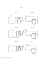
[00053] De acordo com uma modalidade, as primeira e segunda bordas são travadas verticalmente por meios do encaixe de uma superfície de travamento superior provida em uma superfície externa do elemento de travamento e de uma superfície de travamento inferior provida em uma parede da ranhura interna de travamento. Em um exemplo, a superfície de travamento superior é provida ao longo de toda a primeira borda e a superfície de travamento inferior é provida ao longo de uma parte da segunda borda. Em outro exemplo, a superfície de travamento superior é provida ao longo de uma parte da primeira borda e a superfície de travamento inferior é provida ao longo de toda a segunda borda.[00053] According to one embodiment, the first and second edges are vertically locked by means of engaging an upper locking surface provided on an outer surface of the locking element and a lower locking surface provided on a wall of the inner groove. of locking. In one example, the upper locking surface is provided along the entire first edge and the lower locking surface is provided along a portion of the second edge. In another example, the upper locking surface is provided along a portion of the first edge and the lower locking surface is provided along the entire second edge.
[00054] Durante o estágio final, o elemento de travamento pode ser comprimido dentro da posição travada para que as superfícies de travamento superior e inferior se encaixem uma na outra, na posição de travamento. De maneira alternativa, o elemento de travamento pode assumir a posição travada por meio de um suave deslocamento para cima e/ou para baixo para que as superfícies de travamento superior e inferior se encaixem uma na outra, na posição de travamento. Por exemplo, a última pode ser obtida com uma superfície de travamento chanfrada superior e/ou inferior. A tira também pode ser comprimida por uma parte inferior do segundo painel que pressiona contra uma parte superior da tira protuberante e/ou do elemento de travamento.[00054] During the final stage, the locking element can be compressed into the locked position so that the upper and lower locking surfaces engage each other in the locked position. Alternatively, the locking element may assume the locked position by gently moving it up and/or down so that the upper and lower locking surfaces engage each other in the locking position. For example, the latter can be achieved with an upper and/or lower beveled locking surface. The strip may also be compressed by a lower part of the second panel pressing against an upper part of the protruding strip and/or the locking element.
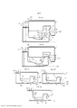
[00055] De acordo com um segundo aspecto da invenção, um conjunto de painéis de chão retangulares e essencialmente idênticos, cada um compreendendo bordas longas, uma primeira borda curta e uma segunda borda curta, é provida. A primeira borda curta e a segunda borda curta são providas com um sistema de travamento mecânico compreendendo uma tira que se estende horizontalmente a partir de uma parte inferior de uma primeira borda curta e uma ranhura de travamento que se abre para baixo e é formada na segunda borda curta. A tira compreende um elemento de travamento projetado para cima que está configurado para cooperar com a ranhura de travamento e travar a primeira borda curta e a segunda borda curta em uma direção horizontal paralela ao plano principal dos painéis e em uma direção vertical perpendicular à direção horizontal. O elemento de travamento compreende uma superfície interna, uma superfície externa e uma superfície superior. A superfície interna é posicionada mais próxima a uma borda superior do primeiro painel do que a superfície externa. A ranhura de travamento compreende uma parede da ranhura externa, uma parede da ranhura interna e uma parede superior da ranhura, a parede da ranhura externa sendo posicionada mais próxima a uma borda superior do segundo painel do que a parede da ranhura interna. O elemento de travamento compreende uma superfície de travamento superior e a ranhura de travamento compreende uma superfície de travamento inferior. Na posição travada, a primeira borda curta e a segunda borda curta compreendem uma primeira e uma segunda seção da borda de junção localizadas ao longo da primeira borda curta e da segunda borda curta. A primeira seção de borda está configurada para que a parede da ranhura externa de travamento e a superfície interna do elemento de travamento entrem em contato uma com a outra ao longo de um plano horizontal HP e trave na primeira borda curta e a segunda borda curta horizontalmente, e a segunda seção de borda está configurada para que, ao longo do plano horizontal HP, haja um espaço entre a parede da ranhura externa de travamento e a superfície interna do elemento de travamento. A superfície de travamento superior do elemento de travamento e a superfície de travamento inferior da ranhura de travamento são configuradas para entrarem em contato uma com a outra e para travar a primeira borda curta e a segunda borda curta verticalmente.[00055] According to a second aspect of the invention, a set of essentially identical rectangular floor panels, each comprising long edges, a first short edge and a second short edge, is provided. The first short edge and the second short edge are provided with a mechanical locking system comprising a strip that extends horizontally from a lower part of a first short edge and a locking groove that opens downwards and is formed in the second. short edge. The strip comprises an upwardly projecting locking element which is configured to cooperate with the locking groove and lock the first short edge and second short edge in a horizontal direction parallel to the main plane of the panels and in a vertical direction perpendicular to the horizontal direction. . The locking element comprises an inner surface, an outer surface and a top surface. The inner surface is positioned closer to a top edge of the first panel than the outer surface. The locking groove comprises an outer groove wall, an inner groove wall and a top groove wall, the outer groove wall being positioned closer to an upper edge of the second panel than the inner groove wall. The locking element comprises an upper locking surface and the locking groove comprises a lower locking surface. In the locked position, the first short edge and the second short edge comprise a first and a second joint edge section located along the first short edge and the second short edge. The first edge section is configured so that the outer locking groove wall and the inner surface of the locking element contact each other along a horizontal plane HP and lock at the first short edge and the second short edge horizontally. , and the second edge section is configured so that, along the horizontal plane HP, there is a space between the wall of the outer locking groove and the inner surface of the locking element. The upper locking surface of the locking element and the lower locking surface of the locking groove are configured to contact each other and to lock the first short edge and the second short edge vertically.
[00056] As modalidades do espaço entre a parede da ranhura externa e a superfície interna são consideravelmente análogas às modalidades descritas acima em relação ao primeiro aspecto, nas quais a referência é feita à descrição acima. Além disso, o comprimento do espaço na direção de comprimento das bordas curtas pode corresponder ao comprimento da segunda seção de borda. De maneira alternativa, o comprimento do espaço pode ser maior que o comprimento da segunda seção de borda.[00056] The modalities of the space between the outer groove wall and the inner surface are considerably analogous to the modalities described above in relation to the first aspect, in which reference is made to the above description. Also, the length of the space in the length direction of the short edges can match the length of the second edge section. Alternatively, the length of the gap can be longer than the length of the second edge section.
[00057] A superfície de travamento superior do elemento de travamento e a superfície de travamento inferior da ranhura de travamento podem ser configuradas para entrarem em contato uma com a outra na segunda seção de borda.[00057] The upper locking surface of the locking element and the lower locking surface of the locking groove can be configured to contact each other in the second edge section.
[00058] A superfície de travamento superior e a superfície de travamento inferior formam uma sobreposição na direção paralela ao plano principal dos painéis e perpendicularmente às bordas curtas. De maneira preferida, há uma sobreposição apenas ao longo de uma porção das bordas curtas, por exemplo, na(s) segunda(s) seção(ões) de borda. Em um primeiro exemplo, a sobreposição é constante ao longo das bordas curtas. De maneira mais específica, a sobreposição é constante na(s) segunda(s) seção(ões) de borda. Em um segundo exemplo, a sobreposição varia ao longo das bordas curtas. A sobreposição pode variar de acordo com a periódicaidade da constante ao longo da(s) segunda(s) seção(ões) de borda.[00058] The upper locking surface and the lower locking surface form an overlap in the direction parallel to the main plane of the panels and perpendicular to the short edges. Preferably, there is an overlap only along a portion of the short edges, for example the second edge section(s). In a first example, the overlap is constant along the short edges. More specifically, the overlap is constant on the second edge section(s). In a second example, the overlap varies along the short edges. The overlap may vary according to the periodicity of the constant along the second edge section(s).
[00059] De acordo com uma modalidade, a superfície de travamento superior se estende ao longo de toda a primeira borda curta. Em um exemplo não limitante, não há nenhuma superfície de travamento inferior na primeira seção de borda.[00059] According to one embodiment, the upper locking surface extends along the entire first short edge. In a non-limiting example, there is no bottom locking surface on the first edge section.
[00060] De acordo com uma modalidade, a superfície de travamento inferior se estende ao longo de toda a segunda borda curta. Em um exemplo não limitante, não há nenhuma superfície de travamento superior provida na primeira seção de borda.[00060] According to one embodiment, the lower locking surface extends along the entire second short edge. In a non-limiting example, there is no top locking surface provided on the first edge section.
[00061] A superfície de travamento superior ou a superfície de travamento inferior pode se estender ao longo de uma porção da primeira e da segunda borda curta, respectivamente.[00061] The upper locking surface or the lower locking surface may extend along a portion of the first and second short edges, respectively.
[00062] De acordo com uma modalidade não limitante, a superfície de travamento superior é posicionada apenas em uma seção mediana da primeira borda curta e a superfície de travamento inferior é provida ao longo de toda a segunda borda curta. Desse modo, a superfície de travamento superior é desprovida das seções de canto da primeira borda curta, de modo que a seção mediana é uma segunda seção de borda e as seções de canto são primeiras seções de borda, a seção mediana sendo posicionada entre as seções de canto. Desse modo, a sobreposição é formada apenas na seção mediana. De acordo com esta modalidade, o espaço é formado como uma cavidade em uma porção mediana da parede da ranhura externa e/ou em uma porção mediana da superfície interna.[00062] According to a non-limiting embodiment, the upper locking surface is positioned only in a midsection of the first short edge and the lower locking surface is provided along the entire second short edge. In this way, the upper locking surface is devoid of the corner sections of the first short edge, so the middle section is a second edge section and the corner sections are first edge sections, the middle section being positioned between the sections. corner. In this way, the overlap is formed only in the middle section. In accordance with this embodiment, the space is formed as a cavity in a middle portion of the outer groove wall and/or in a middle portion of the inner surface.
[00063] A borda superior de um painel pode ser a porção do painel ao longo de uma borda curta do mesmo. A borda superior pode ser mais próxima ao lado frontal do que o lado traseiro do painel. Além disso, a borda superior do primeiro painel pode ser provida em uma parede lateral de uma indentação provida ao longo da primeira borda curta do primeiro painel. A projeção ao longo da segunda borda curta do segundo painel pode ser adaptada para ser inserida na indentação. Além disso, a borda superior do segundo painel pode ser provida na segunda borda curta do segundo painel.[00063] The top edge of a panel may be the portion of the panel along a short edge of the panel. The top edge may be closer to the front side than the back side of the panel. Furthermore, the upper edge of the first panel may be provided in a side wall with an indentation provided along the first short edge of the first panel. The projection along the second short edge of the second panel can be adapted to be inserted into the indentation. Furthermore, the upper edge of the second panel can be provided on the second short edge of the second panel.
[00064] A primeira seção de borda pode ser localizada mais próxima a uma borda longa do que a segunda seção de borda. De maneira alternativa, a segunda seção de borda pode ser localizada mais próxima a uma borda longa do que a primeira seção de borda. As primeiras e/ou segundas seções de borda podem ser posicionadas nas seções de canto de maneira precisamente análoga ao primeiro aspecto explicado acima.[00064] The first edge section can be located closer to a long edge than the second edge section. Alternatively, the second edge section may be located closer to a long edge than the first edge section. The first and/or second edge sections can be positioned on the corner sections in a manner precisely analogous to the first aspect explained above.
[00065] O sistema de travamento pode ser configurado para ser travado por meio do deslocamento vertical da segunda borda curta contra a primeira borda curta. O conceito de "deslocamento vertical" foi definido acima, em relação ao primeiro aspecto.[00065] The locking system can be configured to lock by shifting the second short edge vertically against the first short edge. The concept of "vertical displacement" was defined above in relation to the first aspect.
[00066] O sistema de travamento pode ser configurado para que um deslocamento vertical da segunda borda curta contra a primeira borda curta, durante um estágio inicial, do deslocamento vertical dobre a tira para cima em direção ao segundo painel para que a superfície de travamento superior e a superfície de travamento inferior se sobreponham.[00066] The locking system can be configured so that a vertical displacement of the second short edge against the first short edge, during an initial stage, of the vertical displacement bends the strip upwards towards the second panel so that the upper locking surface and the lower locking surface overlap.
[00067] A tira pode ser configurada para dobrar-se para cima em direção à porção de um lado frontal do segundo painel. A porção pode ser uma porção externa do lado frontal. A flexão ascendente da tira pode compreender pelo menos uma ação dentre um deslocamento vertical para cima, um deslocamento horizontal para dentro e uma rotação. De maneira opcional, a flexão ascendente pode ser combinada com a torção e/ou a compressão da tira.[00067] The strip can be configured to fold up towards the portion of a front side of the second panel. The portion may be an outer portion of the front side. Upward bending of the strip may comprise at least one action of upward vertical displacement, inward horizontal displacement and rotation. Optionally, upward bending can be combined with twisting and/or compressing the strip.
[00068] A superfície de travamento inferior pode ser essencialmente horizontal. De maneira alternativa, a superfície de travamento inferior pode ser inclinada. O ângulo da superfície de travamento inferior em relação a um plano principal do segundo painel pode estar entre 0° e 45° graus, por exemplo, 15°, 20° ou 25°.[00068] The bottom locking surface can be essentially horizontal. Alternatively, the lower locking surface may be angled. The angle of the lower locking surface relative to a principal plane of the second panel may be between 0° and 45° degrees, for example 15°, 20° or 25°.
[00069] De acordo com uma modalidade, a superfície de travamento inferior é plana. De acordo com uma modalidade alternativa, no entanto, a superfície de travamento inferior pode ser curvada. A curvatura pode ser positiva ou negativa, ou seja, convexa ou côncava, na direção perpendicular ao plano vertical.[00069] According to one embodiment, the lower locking surface is flat. According to an alternative embodiment, however, the lower locking surface may be curved. The curvature can be positive or negative, that is, convex or concave, in the direction perpendicular to the vertical plane.
[00070] O formato da superfície de travamento inferior pode corresponder ao formato da superfície de travamento superior - parcialmente ou totalmente.[00070] The shape of the lower locking surface can match the shape of the upper locking surface - partially or fully.
[00071] Uma linha tangente TL até a superfície de travamento inferior pode cruzar a parede da ranhura externa de travamento.[00071] A tangent line TL to the lower locking surface may cross the outer locking groove wall.
[00072] A superfície de travamento superior pode ser localizada na superfície externa do elemento de travamento. A superfície de travamento inferior pode ser localizada na parede da ranhura interna de travamento.[00072] The upper locking surface can be located on the outer surface of the locking element. The lower locking surface can be located on the wall of the internal locking groove.
[00073] A superfície de travamento superior pode ser espaçada verticalmente para cima a partir de uma superfície superior da tira. A superfície superior da tira pode ser a superfície provida na tira da primeira borda curta. A superfície superior da tira pode ser pelo menos parcialmente plana. Além disso, uma porção da superfície superior da tira pode ser curvada. Na posição travada, pelo menos uma porção da superfície superior da tira pode se encaixar na projeção da segunda borda curta do segundo painel. Em particular, pelo menos uma porção da superfície superior da tira pode se encaixar na projeção em uma primeira seção de borda, bem como em uma segunda seção de borda.[00073] The upper locking surface may be spaced vertically upward from an upper surface of the strip. The top surface of the strip may be the surface provided on the first short edge strip. The top surface of the strip may be at least partially flat. In addition, a portion of the top surface of the strip may be curved. In the locked position, at least a portion of the top surface of the strip can engage the projection of the second short edge of the second panel. In particular, at least a portion of the top surface of the strip may fit the projection on a first edge section as well as a second edge section.
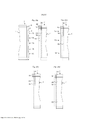
[00074] De acordo com um terceiro aspecto da invenção, um conjunto de painéis de chão essencialmente idênticos é provido com um sistema de travamento mecânico compreendendo uma tira que se estende horizontalmente a partir de uma parte inferior de uma primeira borda e uma ranhura de travamento que se abre para baixo e é formada em uma segunda borda adjacente. A tira compreendendo um elemento de travamento projetado para cima, o qual está configurado para cooperar com a ranhura de travamento para travar a primeira borda e a segunda borda em uma direção horizontal paralela ao plano principal dos painéis e em uma direção vertical perpendicular à direção horizontal. O elemento de travamento e a ranhura de travamento compreendem uma superfície de travamento superior e uma superfície de travamento inferior, as quais estão configuradas para travar os painéis verticalmente. Os painéis de chão são caracterizados pelo fato de que a superfície de travamento superior está localizada em uma parte superior do elemento de travamento que faceia uma borda superior do primeiro painel e que a superfície de travamento superior é inclinada ou arredondada e se estende a partir do elemento de travamento e em direção a uma parte interna do painel para que uma linha tangente até a superfície de travamento superior do elemento de travamento cruze a borda.[00074] According to a third aspect of the invention, a set of essentially identical floor panels is provided with a mechanical locking system comprising a strip extending horizontally from a lower part of a first edge and a locking groove. which opens downwards and is formed on a second adjacent edge. The strip comprising an upwardly projecting locking element which is configured to cooperate with the locking groove to lock the first edge and the second edge in a horizontal direction parallel to the main plane of the panels and in a vertical direction perpendicular to the horizontal direction . The locking element and the locking groove comprise an upper locking surface and a lower locking surface, which are configured to lock the panels vertically. Floor panels are characterized in that the upper locking surface is located on an upper part of the locking element that faces an upper edge of the first panel and that the upper locking surface is angled or rounded and extends from the floor. locking element and towards an inner part of the panel so that a tangent line to the upper locking surface of the locking element crosses the edge.
[00075] A parte superior do elemento de travamento pode facear a borda superior do primeiro painel. Além disso, a linha tangente pode cruzar a primeira borda.[00075] The top of the locking element can face the top edge of the first panel. Also, the tangent line can cross the first edge.
[00076] A linha tangente pode ser especificada em a uma vista lateral transversal dos painéis. A linha tangente pode cruzar a primeira borda em uma parte superior da primeira borda.[00076] The tangent line can be specified in a cross-sectional side view of the panels. The tangent line can cross the first edge at a top of the first edge.
[00077] Em um exemplo não limitante, a superfície de travamento superior é plana. Neste caso, a superfície de travamento superior e plana pode ser inclinada em relação a um lado frontal do primeiro painel em um ângulo entre 0° e 45°, por exemplo, 20° ou 25°. Em outro exemplo não limitante, a superfície de travamento superior é arredondada ou, equivalentemente curvada. Neste caso, a curvatura da superfície de travamento superior pode ser positiva ou negativa, em outras palavras, a superfície de travamento superior pode ser convexa ou côncava na direção perpendicular ao plano vertical. No caso de uma superfície de travamento superior arredondada, linhas tangentes em um ou vários pontos da superfície de travamento superior podem cruzar a primeira borda, como visto a partir de uma vista lateral transversal dos painéis.[00077] In a non-limiting example, the top locking surface is flat. In this case, the flat top locking surface can be inclined with respect to a front side of the first panel at an angle between 0° and 45°, for example 20° or 25°. In another non-limiting example, the upper locking surface is rounded or, equivalently, curved. In this case, the curvature of the upper locking surface can be positive or negative, in other words, the upper locking surface can be convex or concave in the direction perpendicular to the vertical plane. In the case of a rounded top locking surface, tangent lines at one or more points on the top locking surface may cross the first edge, as seen from a cross-sectional side view of the panels.
[00078] O formato da superfície de travamento superior pode corresponder ao formato da superfície de travamento inferior - parcialmente ou totalmente.[00078] The shape of the upper locking surface can match the shape of the lower locking surface - partially or fully.
[00079] O sistema de travamento pode ser configurado para ser travado por meio do deslocamento vertical da segunda borda contra a primeira borda.[00079] The locking system can be configured to be locked by vertically shifting the second edge against the first edge.
[00080] O sistema de travamento pode ser configurado para que um deslocamento vertical da segunda borda contra a primeira borda, durante o travamento, dobre a tira para baixo e vire a parte superior do elemento de travamento externamente para longe da borda superior.[00080] The locking system can be configured so that a vertical displacement of the second edge against the first edge, during locking, bends the strip down and turns the top of the locking element outwardly away from the top edge.
[00081] As superfícies de travamento podem ser configuradas para que as superfícies de travamento superior e inferior compreendam superfícies de orientação superior e inferior que se sobrepõem durante a flexão descendente da tira.[00081] The locking surfaces can be configured so that the upper and lower locking surfaces comprise upper and lower guiding surfaces that overlap during downward bending of the strip.
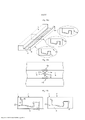
[00082] De acordo com um quarto aspecto da invenção, um método para produzir um sistema de travamento nas bordas de painéis de construção é provido. Os painéis de construção compreendem um núcleo e uma superfície de travamento formada no núcleo e se estende de modo essencialmente horizontal para que uma linha tangente até uma parte da superfície de travamento cruze uma parede adjacente essencialmente vertical formada na borda do painel adjacente à superfície de travamento. O método compreende: formar uma tira em uma parte inferior de uma primeira borda de um painel e um elemento de travamento em uma parte externa da tira protuberante, formar uma ranhura de travamento em uma segunda borda do painel e formar uma superfície de travamento essencialmente horizontal em uma parede da ranhura de travamento ou no elemento de travamento deslocando-se o painel contra uma ferramenta de entalhe fixa.[00082] According to a fourth aspect of the invention, a method for producing a locking system at the edges of building panels is provided. The building panels comprise a core and a locking surface formed in the core and extending substantially horizontally so that a tangent line to a portion of the locking surface intersects an adjacent substantially vertical wall formed at the edge of the panel adjacent the locking surface. . The method comprises: forming a strip on a lower part of a first edge of a panel and a locking element on an outside of the protruding strip, forming a locking groove on a second edge of the panel and forming an essentially horizontal locking surface in a wall of the locking groove or in the locking element by moving the panel against a fixed notching tool.
[00083] De acordo com um quinto aspecto da descrição, um conjunto de painéis de chão essencialmente idênticos é provido com um sistema de travamento mecânico compreendendo uma tira que se estende horizontalmente a partir de uma parte inferior de uma primeira borda e uma ranhura de travamento que se abre para baixo e é formada em uma segunda borda adjacente. A tira compreende um elemento de travamento projetado para cima que está configurado para cooperar com a ranhura de travamento e travar as primeira e segunda bordas em uma direção horizontal paralela ao plano principal dos primeiro e segundo painéis e em uma direção vertical perpendicular à direção horizontal. O sistema de travamento está configurado para ser travado por meio do deslocamento vertical da segunda borda contra a primeira borda, na qual uma porção superior da tira é configurada para dobrar- se para cima em direção ao segundo painel.[00083] According to a fifth aspect of the description, a set of essentially identical floor panels is provided with a mechanical locking system comprising a strip extending horizontally from a lower part of a first edge and a locking groove. which opens downwards and is formed on a second adjacent edge. The strip comprises an upwardly projecting locking element which is configured to cooperate with the locking groove and lock the first and second edges in a horizontal direction parallel to the principal plane of the first and second panels and in a vertical direction perpendicular to the horizontal direction. The locking system is configured to be locked by vertical displacement of the second edge against the first edge, in which an upper portion of the strip is configured to fold upwards towards the second panel.
[00084] De maneira opcional, a flexão ascendente da tira pode ser combinada com pelo menos uma ação dentre a torção ou a compressão da tira e/ou do elemento de travamento.[00084] Optionally, the upward bending of the strip can be combined with at least one action among the twisting or compression of the strip and/or the locking element.
[00085] O quinto aspecto da descrição é consideravelmente análogo ao primeiro aspecto, exceto pelo estágio final do deslocamento vertical orientado para baixo, no qual referência é feita às modalidades acima e aos exemplos discutidos em relação às mesmas.[00085] The fifth aspect of the description is considerably analogous to the first aspect, except for the final stage of downward-oriented vertical displacement, in which reference is made to the above modalities and the examples discussed in relation to them.
[00086] De maneira adicional, o elemento de travamento pode assumir a posição travada por meio de um deslocamento suave para cima, de modo que as superfícies de travamento superior e inferior possam se encaixar uma na outra na posição de travamento. De maneira alternativa, ele pode ser comprimido na posição travada.[00086] Additionally, the locking element can assume the locked position by means of a smooth upward displacement, so that the upper and lower locking surfaces can engage each other in the locking position. Alternatively, it can be compressed in the locked position.
[00087] De acordo com um sexto aspecto da descrição, um conjunto de painéis de chão essencialmente idênticos é provido com um sistema de travamento mecânico compreendendo uma tira que se estende horizontalmente a partir de uma parte inferior de uma primeira borda e uma ranhura de travamento que se abre para baixo e é formada em uma segunda borda adjacente. A tira compreende um elemento de travamento projetado para cima que está configurado para cooperar com a ranhura de travamento e travar as primeira e segunda bordas em uma direção horizontal paralela ao plano principal dos primeiro e segundo painéis e em uma direção vertical perpendicular à direção horizontal. O sistema de travamento está configurado para ser travado por meio do deslocamento vertical da segunda borda contra a primeira borda, de modo que a porção da tira seja configurada para ser deslocada na direção interna por meio de torção e/ou compressão da tira.[00087] According to a sixth aspect of the description, a set of essentially identical floor panels is provided with a mechanical locking system comprising a strip extending horizontally from a lower part of a first edge and a locking groove. which opens downwards and is formed on a second adjacent edge. The strip comprises an upwardly projecting locking element which is configured to cooperate with the locking groove and lock the first and second edges in a horizontal direction parallel to the principal plane of the first and second panels and in a vertical direction perpendicular to the horizontal direction. The locking system is configured to be locked by vertical displacement of the second edge against the first edge, so that the portion of the strip is configured to be displaced in the inward direction by twisting and/or compressing the strip.
[00088] O sexto aspecto da descrição é consideravelmente análogo ao primeiro aspecto, exceto pelo fato de que as flexões ascendente e descendente foram substituídas por torção e/ou compressão da tira, no qual referência é feita às modalidades acima e aos exemplos discutidos em relação às mesmas. Em particular, a porção da tira pode ser uma porção do elemento de travamento, por exemplo, uma porção superior do elemento de travamento. Além disso, a porção superior do elemento de travamento pode ser configurada para ser deslocada, durante o travamento, para dentro de um espaço provido entre uma parede da ranhura externa de travamento e uma superfície interna do elemento de travamento.[00088] The sixth aspect of the description is considerably analogous to the first aspect, except that upward and downward bending has been replaced by twisting and/or compressing the strap, in which reference is made to the above modalities and the examples discussed in relation to the same. In particular, the strip portion may be a portion of the locking element, for example, an upper portion of the locking element. Furthermore, the upper portion of the locking element may be configured to be displaced, during locking, into a space provided between an outer locking groove wall and an internal surface of the locking element.
[00089] De maneira adicional, o sistema de travamento também pode ser configurado para ser travado por meio do deslocamento de uma porção da tira na direção externa. Por exemplo, a tira pode ser destorcida e/ou descomprimida pelo menos parcialmente em direção a uma posição inicial não travada da tira.[00089] Additionally, the locking system can also be configured to be locked by shifting a portion of the strip in the outward direction. For example, the strip may be untwisted and/or decompressed at least partially towards an unlatched initial position of the strip.
[00090] De acordo com um sétimo aspecto da descrição, provê-se um conjunto de painéis de chão essencialmente idênticos compreendendo um primeiro painel e um segundo painel adjacente e sendo provido com um sistema de travamento mecânico compreendendo uma tira que se estende horizontalmente a partir de uma parte inferior de uma primeira borda do primeiro painel e uma primeira ranhura de travamento que se abre para baixo e uma segunda ranhura de travamento que se abre para baixo e é formada em uma segunda borda do segundo painel. A tira compreende um primeiro elemento de travamento projetado para cima e um segundo elemento de travamento projetado para cima provido dentro do primeiro elemento de travamento. Além disso, o segundo elemento de travamento está configurado para cooperar com a segunda ranhura de travamento e para travar as primeira e segunda bordas em uma direção horizontal perpendicular a um plano vertical definido pela junção adjacente às primeira e segunda bordas. O primeiro elemento de travamento está configurado para cooperar com a primeira ranhura de travamento e para travar as primeira e segunda bordas em uma direção vertical de modo perpendicular à dita direção horizontal. O sistema de travamento está configurado para ser travado por meio do deslocamento vertical da segunda borda contra a primeira borda, de modo que uma porção superior do elemento de travamento seja deslocada dentro de um espaço. O espaço é definido por uma cavidade entre uma parede da ranhura externa da primeira ranhura de travamento e uma superfície interna do primeiro elemento de travamento em um estado travado dos painéis.[00090] According to a seventh aspect of the description, there is provided a set of essentially identical floor panels comprising a first panel and an adjacent second panel and being provided with a mechanical locking system comprising a strip extending horizontally from there. of a lower part of a first edge of the first panel and a first downwardly opening locking groove and a downwardly opening second locking groove formed in a second edge of the second panel. The strip comprises an upwardly projecting first locking element and an upwardly projecting second locking element provided within the first locking element. Furthermore, the second locking element is configured to cooperate with the second locking groove and to lock the first and second edges in a horizontal direction perpendicular to a vertical plane defined by the joint adjacent the first and second edges. The first locking element is configured to cooperate with the first locking groove and to lock the first and second edges in a vertical direction perpendicular to said horizontal direction. The locking system is configured to be locked by vertically shifting the second edge against the first edge so that an upper portion of the locking member is shifted within a space. The space is defined by a cavity between an outer groove wall of the first locking groove and an inner surface of the first locking element in a locked state of the panels.
[00091] De acordo com uma modalidade, as primeira e segunda ranhuras de travamento são separadas por uma projeção estendida para baixo.[00091] According to one embodiment, the first and second locking grooves are separated by a downwardly extending projection.
[00092] De acordo com outra modalidade, as primeira e segunda ranhuras de travamento fazem parte de uma ranhura comum. A ranhura comum pode ter uma parede interna que coincide com uma parede da primeira ranhura de travamento e uma parede externa que coincide com uma parede da segunda ranhura de travamento. Além disso, a ranhura comum pode ter uma parede intermediária conectando as paredes superiores da ranhura das primeira e segunda ranhuras de travamento.[00092] According to another embodiment, the first and second locking grooves form part of a common groove. The common groove may have an inner wall that coincides with a wall of the first locking groove and an outer wall that coincides with a wall of the second locking groove. Furthermore, the common groove may have an intermediate wall connecting the upper groove walls of the first and second locking grooves.
[00093] O sétimo aspecto da descrição é consideravelmente análogo ao primeiro aspecto, no qual referência é feita às modalidades acima e aos exemplos discutidos em relação às mesmas. Em particular, compreende-se que a porção superior do elemento de travamento pode, de maneira opcional, se dobrar para cima, pode ser comprimida e/ou torcida e possivelmente também pode ser dobrada para baixo. Além disso, todas as modalidades do espaço de acordo com o primeiro aspecto podem ser combinadas com o sétimo aspecto.[00093] The seventh aspect of the description is considerably analogous to the first aspect, in which reference is made to the above embodiments and the examples discussed in connection therewith. In particular, it is understood that the upper portion of the locking element can optionally be bent upwards, can be compressed and/or twisted and possibly can also be bent downwards. Furthermore, all modalities of space according to the first aspect can be combined with the seventh aspect.
[00094] De maneira mais genérica, enfatiza-se que as modalidades de acordo com os vários aspectos da descrição podem ser combinadas em parte ou em sua totalidade umas com as outras. De maneira adicional, compreende-se que em todos os aspectos acima a flexão, torção, compressão ou deformação podem ser elásticas ou rígidas. Breve Descrição dos Desenhos[00094] More generally, it is emphasized that the modalities according to the various aspects of the description can be combined in part or in their entirety with each other. In addition, it is understood that in all of the above aspects the bending, torsion, compression or deformation may be elastic or rigid. Brief Description of Drawings
[00095] Uma descrição será feita a seguir em conexão com modalidades exemplares e, mais detalhadamente, com referência aos desenhos exemplares em anexo, nos quais:[00095] A description will be given below in connection with exemplary embodiments and, in more detail, with reference to the attached exemplary drawings, in which:
[00096] As Figuras 1a-g ilustram um sistema de travamento por dobra de acordo com princípios conhecidos.[00096] Figures 1a-g illustrate a bend locking system according to known principles.
[00097] As Figuras 2a-c ilustram princípios conhecidos para formar sistemas de travamento.[00097] Figures 2a-c illustrate known principles for forming locking systems.
[00098] As Figuras 3a-e ilustram flexão vertical e separação de borda.[00098] Figures 3a-e illustrate vertical bending and edge separation.
[00099] As Figuras 4a-f ilustram flexão de partes protuberantes. As Figuras 5a-b ilustram uma primeira e uma segunda seção de borda de um sistema de travamento de acordo com uma modalidade.[00099] Figures 4a-f illustrate bending of protruding parts. Figures 5a-b illustrate first and second edge sections of a locking system according to one embodiment.
[000100] As Figuras 6a-b ilustram as primeira e segunda seções de borda do sistema de travamento das Figuras 5a-b na posição travada.[000100] Figures 6a-b illustrate the first and second edge sections of the locking system of Figures 5a-b in the locked position.
[000101] As Figuras 7a-d ilustram modalidades alternativas das primeira e segunda seções de borda.[000101] Figures 7a-d illustrate alternative embodiments of the first and second edge sections.
[000102] As Figuras 8a-c ilustram um deslocamento vertical de uma primeira seção de borda de acordo com uma modalidade.[000102] Figures 8a-c illustrate a vertical displacement of a first edge section according to one embodiment.
[000103] As Figuras 9a-e ilustram um deslocamento vertical de uma segunda seção de borda de acordo com uma modalidade.[000103] Figures 9a-e illustrate a vertical displacement of a second edge section according to one embodiment.
[000104] As Figuras 10a-c ilustram cabeçotes de ferramenta oscilante e ferramentas giratórias de entalhe de acordo com uma modalidade.[000104] Figures 10a-c illustrate oscillating tool heads and rotary slotting tools according to one embodiment.
[000105] As Figuras 11a-f ilustram a formação de uma seção de borda com cabeçotes de ferramenta oscilante de acordo com uma modalidade.[000105] Figures 11a-f illustrate the formation of an edge section with oscillating tool heads according to one embodiment.
[000106] As Figuras 12a-b ilustram a formação com ferramentas de entalhe de acordo com diferentes modalidades.[000106] Figures 12a-b illustrate forming with carving tools according to different embodiments.
[000107] As Figuras 13a-e ilustram uma borda de painel compreendendo uma primeira e uma segunda seção de borda de acordo com uma modalidade.[000107] Figures 13a-e illustrate a panel edge comprising a first and a second edge section according to one embodiment.
[000108] As Figuras 14a-e ilustram diferentes modalidades de sistemas de travamento e sua formação.[000108] Figures 14a-e illustrate different modalities of locking systems and their formation.
[000109] As Figuras 15a-d ilustram um sistema de travamento de acordo com um segundo princípio.[000109] Figures 15a-d illustrate a locking system according to a second principle.
[000110] As Figuras 16a-c ilustram uma seção de borda do sistema de travamento de acordo com o segundo princípio.[000110] Figures 16a-c illustrate an edge section of the locking system according to the second principle.
[000111] As Figuras 17a-d ilustram um método para reforçar uma parte protuberante de acordo com uma modalidade.[000111] Figures 17a-d illustrate a method for reinforcing a protruding part according to one embodiment.
[000112] As Figuras 18a-f ilustram uma modalidade de um método de produção para formar um sistema de travamento.[000112] Figures 18a-f illustrate one embodiment of a production method for forming a locking system.
[000113] As Figuras 19a-f ilustram outra modalidade de um método de produção para formar um sistema de travamento.[000113] Figures 19a-f illustrate another embodiment of a production method for forming a locking system.
[000114] As Figuras 20a-d ilustram o travamento de bordas longas e curtas de acordo com uma modalidade e a formação de um sistema de travamento de acordo com uma modalidade.[000114] Figures 20a-d illustrate locking long and short edges in accordance with one embodiment and forming a locking system in accordance with one embodiment.
[000115] As Figuras 21a-e ilustram um sistema de travamento de borda longa de acordo com uma modalidade.[000115] Figures 21a-e illustrate a long edge locking system according to one embodiment.
[000116] As Figuras 22a-d ilustram um sistema de travamento de borda longa de acordo com uma modalidade.[000116] Figures 22a-d illustrate a long edge locking system according to one embodiment.
[000117] As Figuras 23a-d ilustram o travamento de componentes de mobília de acordo com uma modalidade.[000117] Figures 23a-d illustrate locking furniture components according to one embodiment.
[000118] As Figuras 24a-f ilustram um sistema de travamento formado de acordo com um terceiro princípio.[000118] Figures 24a-f illustrate a locking system formed according to a third principle.
[000119] As Figuras 25a-d ilustram várias modalidades de ranhuras flexíveis providas em um segundo painel de chão.[000119] Figures 25a-d illustrate various embodiments of flexible grooves provided in a second floor panel.
[000120] As Figuras 26a-b ilustram várias modalidades de fendas providas no primeiro painel de chão.[000120] Figures 26a-b illustrate various modes of slots provided in the first floor panel.
[000121] As Figuras 27a-b ilustram uma modalidade com um elemento de travamento flexível e dobrável.[000121] Figures 27a-b illustrate an embodiment with a flexible and collapsible locking element.
[000122] As Figuras 1a - 1f mostram alguns exemplos de conhecidos sistemas de travamento dobrados feitos integralmente com o núcleo 5, os quais são destinados a travar bordas curtas por meio de um deslocamento vertical de uma segunda borda do segundo painel 1' contra uma primeira borda de um primeiro painel 1. Todos os sistemas compreendem uma tira horizontalmente projetada 6 com um elemento de travamento 8 na primeira borda do primeiro painel 1 que coopera com uma ranhura de travamento 14 na segunda borda do segundo painel 1' e trava as bordas dos painéis 1, 1' horizontalmente. Diferentes métodos são usados para travar as bordas verticalmente.[000122] Figures 1a - 1f show some examples of known folded locking systems made integrally with the
[000123] A Figura 1a mostra que uma pequena lingueta 10, que coopera com uma ranhura de lingueta 9, pode ser usada para o travamento vertical. A compressão da lingueta 10 é necessária para efetuar o travamento. As bordas superiores são, durante o deslocamento vertical, espaçadas umas das outras em um espaço S, que corresponde à protuberância horizontal da lingueta 10. As bordas adjacentes devem ser unidas durante o estágio final do travamento. A fricção entre as bordas longas, que durante o estágio final do travamento, estão praticamente alinhadas no sentido horizontal e estão na posição travada, impede tal ação de união, havendo assim um maior risco de que as bordas sejam travadas em um espaço ou que o elemento de travamento 8 seja danificado. Uma considerável força por pressão é necessária para comprimir as bordas umas nas outras e as folgas de espessura podem criar outros problemas, especialmente se o segundo painel 1' for mais espesso que o primeiro painel 1 e se chocar com o subpiso antes de as superfícies superiores serem alinhadas horizontalmente. O sistema de travamento não é adequado para travar painéis que compreendam, por exemplo, um núcleo de HDF ou outros materiais não compressíveis.[000123] Figure 1a shows that a
[000124] A Figura 1b mostra um sistema de travamento similar com duas linguetas 10a, 10b e duas ranhuras de lingueta 9a, 9b. Tal sistema exige a compressão do material e causa a separação das bordas durante o travamento. As superfícies de travamento são quase verticais e possuem um ângulo de travamento LA de cerca de 60 graus contra o plano horizontal H. As linguetas protuberantes são muito pequenas e se projetam por alguns milímetros, o que corresponde às folgas normais de produção e resulta em um sistema de travamento ineficiente ou sem superfícies de travamento sobrepostas.[000124] Figure 1b shows a similar locking system with two
[000125] A Figura 1c mostra um sistema de travamento com duas linguetas 10a, 10b. O elemento de travamento compreende uma superfície de travamento que é inclinada para cima em direção à borda superior de modo a aumentar a resistência ao travamento vertical. Tal sistema de travamento é ainda mais difícil de travar do que os sistemas de travamento descritos acima e sofre das mesmas desvantagens.[000125] Figure 1c shows a locking system with two
[000126] A Figura 1d mostra uma modalidade que se baseia em elementos de travamento projetados para baixo, os quais são destinados a dobrar-se interiormente contra eles mesmos para que duas linguetas 10a, 10b possam ser inseridas nas ranhuras de lingueta. A flexibilidade que pode ser obtida ao longo da extensão vertical limitada dos elementos de travamento em um material de HDF não é suficiente para obter a força de travamento necessária para aplicações de piso. No entanto, o sistema de travamento elimina as forças de separação durante o travamento.[000126] Figure 1d shows an embodiment which is based on downwardly projecting locking elements, which are intended to fold inwardly against themselves so that two
[000127] A Figura 1e mostra um sistema de travamento no qual uma flexibilidade similar é obtida com uma ranhura formada atrás da ranhura de travamento 14. Tais sistemas de travamento sofrem das mesmas desvantagens que o sistema de travamento mostrado na Figura 1d. Um sistema de travamento similar também pode compreender superfícies de travamento 10b, 9b que são regiões encurtadas, por exemplo, conforme descrito no WO 2010/100046, de modo a reduzir os danos do meio de travamento durante a instalação quando o material está comprimido. Na prática, nenhuma redução de danos pode ser obtida.[000127] Figure 1e shows a locking system in which similar flexibility is achieved with a groove formed behind the locking
[000128] A Figura 1f mostra um sistema de travamento que compreende uma tira 6 que é dobrada para baixo durante o deslocamento vertical. O sistema de travamento é projetado para ser usado em conjunto com um método de instalação, no qual as bordas longas dos primeiro e segundo painéis estão em uma posição angulada para que as forças de fricção sejam reduzidas a um nível em que o elemento de travamento, durante um aperto ascendente, é capaz de automaticamente unir as bordas. A maior desvantagem, é que a instalação deve ser feita com painéis na posição angulada e isso é mais complicado do que a instalação convencional por meio de uma única ação de dobragem.[000128] Figure 1f shows a locking system comprising a
[000129] A Figura 1g mostra sistemas de travamento, os quais podem compreender fendas 6a na tira de travamento, por exemplo, conforme descrito no documento US 2010/0037550, ou fendas 14a atrás da ranhura de travamento, por exemplo, conforme descrito no WO 2008/116623. Tais fendas podem aumentar a flexibilidade e as possibilidades de deslocamento horizontal dos elementos de travamento de maneira considerável, e um travamento muito fácil pode ser obtido. O principal problema é que tais fendas também aumentam a flexibilidade vertical e flexibilidade, o que resultará em uma resistência de travamento muito baixa na direção vertical. Portanto, as tentativas para introduzir tais sistemas de travamento fracassaram.[000129] Figure 1g shows locking systems which may comprise
[000130] As Figuras 2a - 2c mostram que a geometria dos sistemas de travamento é restringida de vários modos pelos métodos de produção, nos quais perfiladores de ponta dupla, compreendendo uma corrente 33, uma correia 34 e várias ferramentas giratórias grandes 17 com um diâmetro de cerca de 20 cm, são usados. As Figuras 2a e 2b mostram que métodos de produção eficientes exigem que ranhuras e protuberâncias sejam formadas com ferramentas giratórias 17, que giram verticalmente ou horizontalmente ou que são anguladas para longe da corrente 33 e a correia 34. A Figura 2c mostra que apenas superfícies de travamento essencialmente verticais podem ser formadas em uma parte interna do elemento de travamento 8 ou na ranhura de travamento 14 e que ferramentas giratórias muito pequenas, com uma baixa capacidade de desfibragem podem ser usadas. Vários dos sistemas de travamento conhecidos não podem ser produzidos de um modo econômico.[000130] Figures 2a - 2c show that the geometry of the locking systems is constrained in various ways by production methods, in which double-ended profilers, comprising a
[000131] As Figuras 3a - 3e, explicam as forças de separação que podem ocorrer durante a flexão vertical, quando o segundo painel 1' está angulado contra um painel previamente instalado 1'' em uma fileira anterior e na qual essa ação de angulagem também conecta uma borda curta do segundo painel 1' a uma borda curta de um primeiro painel 1, conforme mostrado na Figura 3a. As bordas curtas são travadas por um movimento do tipo tesoura, no qual as bordas curtas são gradualmente travadas a partir de uma borda longa até a outra borda longa. As bordas curtas adjacentes dos primeiro e segundo painéis 1, 1' possuem, ao longo de suas bordas, uma seção inicial 30 que se torna ativa durante uma primeira etapa inicial da ação de flexão, uma seção mediana 31 que se torna ativa durante um segundo estágio da ação de flexão e uma seção final 32 que se torna ativa durante uma terceira etapa final da ação de flexão. O sistema de travamento mostrado se baseia em uma modalidade com uma tira 6 que, durante o deslocamento vertical, se dobra para baixo e em seguida, se dobra para cima. A Figura 3b mostra que uma parte da borda, que está próxima à borda longa onde a angulagem ocorre, está quase na posição travada, conforme mostrado pela seção transversal A-A, quando o elemento de travamento 8 e a ranhura de travamento 14 das seções medianas B-B ainda estão espaçadas umas das outras verticalmente, conforme mostrado na Figura 3c, e quando as seções de borda C-C que estão mais distantes da borda longa onde a angulagem ocorre estão espaçadas umas das outras verticalmente sem qualquer contato entre as seções transversais C-C, conforme mostrado na Figura 3d. A Figura 3e mostra a etapa final do travamento, quando as bordas são unidas por uma força de tração que é suficiente para superar a fricção entre as bordas longas do primeiro painel instalado 1'' e do segundo painel 1'. A fricção pode ser substancial, especialmente quando os painéis são longos ou quando um material com alta fricção é usado como núcleo. A alta fricção é, em grande medida, causada pela geometria do sistema de travamento de borda longa que deve ser formado com um encaixe firme entre a lingueta e a ranhura de lingueta de modo a evitar o som de rangido.[000131] Figures 3a - 3e explain the separation forces that can occur during vertical bending, when the second panel 1' is angled against a previously installed panel 1'' in a previous row and in which this angling action also connects a short edge of the second panel 1' to a short edge of a
[000132] As Figuras 4a e 4b mostram um sistema de travamento com peça única, formado em um painel de chão laminado que compreende um núcleo de HDF. O sistema de travamento é travado com aperto horizontal. O material de HDF compreende fibras de madeira 24 que, durante a produção de HDF, assumem uma posição essencialmente horizontal no material do núcleo. O perfil densidade é para que, as partes superior 5a e inferior 5b do núcleo 5 tenham uma densidade maior que as partes medianas. Essas porções externas também são reforçadas pela resina de melamina do papel impregnado da superfície 2 e nas camadas estabilizadoras 3 que, durante a laminação, penetram no núcleo 5. Isso permite que uma borda flexível resistente 6 possa ser formada, a qual, durante o travamento, dobra-se para baixo. A função de aperto é apoiada pela aba superior 9' que se dobra levemente para cima e a lingueta protuberante 10 que se dobra levemente para baixo. O elemento de travamento pode ser facilmente formado por um ângulo de travamento alto e com superfícies de travamento essencialmente verticais.[000132] Figures 4a and 4b show a one-piece locking system formed in a laminated floor panel comprising an HDF core. The locking system is locked with horizontal grip. The HDF material comprises wood fibers 24 which, during the production of HDF, assume an essentially horizontal position in the core material. The density profile is such that the
[000133] Como uma comparação, a flexão dos elementos de travamento verticalmente protuberantes 8 é mostrada nas Figuras 4c- 4f. As Figuras 4c e 4d mostram um elemento de travamento 8 que, durante o deslocamento vertical é dobrado para fora. A flexão ocorre na parte mais macia do núcleo de HDF e uma rachadura 23 ocorrerá geralmente na parte inferior do elemento de travamento 8. As Figuras 4e e 4f mostram um elemento de travamento 8 que é usado para travar contra uma ranhura de travamento 14 em uma direção horizontal H e uma direção vertical V. O travamento pode ocorrer apenas com a compressão do material, o que causa danos e rachaduras 23, 23' no sistema de travamento.[000133] As a comparison, the bending of the vertically protruding
[000134] As Figuras 5a e 5b mostram uma primeira modalidade da invenção, de acordo com um primeiro princípio. Um conjunto de painéis similares de chão 1, 1' é provido, na qual cada painel de chão compreende, de maneira preferida, uma camada de superfície 2, um núcleo 5, uma camada estabilizadora 3 e uma primeira e uma segunda borda curta. Uma primeira borda curta 4c de um primeiro painel de chão 1 pode ser travado em uma segunda borda curta adjacente 4d de um segundo painel de chão 1' similar com um deslocamento vertical da segunda borda contra a primeira borda. De acordo com a presente modalidade, o deslocamento vertical é um movimento de tesoura vertical causado pela mesma ação de angulagem que é usada para conectar as bordas longas dos painéis. A primeira borda curta 4c compreende uma tira horizontalmente projetada 6 com um elemento de travamento verticalmente protuberante 8 em sua parte externa, que coopera com uma ranhura de travamento que se abre para baixo 14 e é formada na segunda borda adjacente 4d.[000134] Figures 5a and 5b show a first embodiment of the invention, according to a first principle. A set of
[000135] De acordo com a presente modalidade, o elemento de travamento 8 é essencialmente rígido e não é destinado a ser dobrado ou comprimido durante o travamento, o que, ao contrário da tecnologia conhecida, é efetuado essencialmente por um deslocamento horizontal da parte superior do elemento de travamento 8 em direção à primeira borda superior 43. Por essencialmente rígido entende-se, neste caso, que durante o travamento, o próprio elemento de travamento é dobrado e/ou comprimido em uma direção horizontal por uma distância HD que é menos que 50% de uma superfície de travamento superior horizontalmente protuberante 11a localizada na parte superior do elemento de travamento 8, conforme mostrado na Figura 6b. O deslocamento do elemento de travamento 8 é efetuado principalmente com a flexão e/ou deformação da tira 6. O elemento de travamento compreende uma superfície interna 8a, uma superfície externa 8b e uma superfície superior ou de topo 8c. A superfície interna 8a está mais próxima a uma borda superior 43 do primeiro painel 1 do que a superfície externa 8b. De maneira mais específica, a distância horizontal entre a superfície interna 8a e a borda superior 43 é menor que a distância horizontal entre a superfície externa 8b e a borda superior 43. De acordo com a presente modalidade, a borda superior 43 é a porção da primeira borda próxima ao lado frontal do primeiro painel 1. Além disso, a borda superior 43 é provida em uma parede lateral 45 de uma indentação 44, a qual é provida na primeira borda. A indentação 44 é aberta para cima e, na posição travada, uma superfície de suporte superior 16 da projeção 46 provida na segunda borda, se encaixa na superfície de suporte inferior 15 da indentação, a qual é uma porção de uma superfície superior da tira 6a da tira 6. A ranhura de travamento 14 compreende uma parede da ranhura externa 14a, uma parede da ranhura interna 14b e uma parede superior da ranhura 14c. A projeção 46 é provida fora da ranhura de travamento 14 e compartilha a parede da ranhura externa 14a com a ranhura de travamento 14. A parede da ranhura externa 14a está mais próxima a uma borda superior 43' do segundo painel 1' do que a parede da ranhura interna 14b. De maneira mais específica, a distância horizontal entre a parede da ranhura externa 14a e a borda superior 43' é menor que a distância horizontal entre a parede da ranhura interna 14b e a borda superior 43'. O elemento de travamento 8 compreende uma superfície de travamento superior 11a formada na superfície externa 8b do elemento de travamento 8 que coopera com uma superfície de travamento inferior 11b formada na parede da ranhura interna 14b e que trava as bordas adjacentes em uma direção vertical. As superfícies de travamento superior 11a e inferior 11b estão espaçadas verticalmente para cima a partir da superfície superior 6a da tira 6. Por exemplo, as superfícies de travamento superior 11a e inferior 11b podem ser espaçadas verticalmente para cima por uma distância vertical de travamento VLD a partir de toda a superfície superior 6a ou a partir da parte mais superior da superfície superior 6a, por exemplo, a superfície de suporte inferior 15 da indentação 40. Em exemplos não limitantes, a VLD pode estar entre 20% e 70%, por exemplo, 30%, 40% ou 50%, da espessura T dos painéis de chão na direção vertical. O elemento de travamento 8 compreende uma primeira superfície de travamento 12a formada na superfície interna 8a do elemento de travamento 8 que coopera com uma segunda superfície de travamento 12b formada na parede da ranhura externa 14a e que trava as bordas adjacentes em uma direção horizontal.[000135] According to the present embodiment, the locking
[000136] De acordo com uma modalidade alternativa, o elemento de travamento 8 pode ser configurado para dobrar-se durante o travamento.[000136] According to an alternative embodiment, the locking
[000137] As bordas adjacentes compreendem, na posição travada, uma primeira seção de borda 7a e uma segunda seção de borda 7b. As seções de borda são caracterizadas pelo fato de que uma seção transversal da ranhura de travamento 14 e/ou uma seção transversal do elemento de travamento 8 varia ao longo das bordas adjacentes dos painéis 1, 1' as quais são formadas com uma geometria básica que é em seguida, modifiicada para que as primeira 7a e segunda 7b seções de borda cooperantes sejam formadas com diferentes geometrias e diferentes funções de travamento. Neste caso, as geometrias e as seções transversais são especificadas em uma vista lateral dos painéis, conforme mostrado nas Figuras 5a e 5b.[000137] Adjacent edges comprise, in the locked position, a
[000138] A primeira seção de borda 7a é preferidamente uma seção inicial 30 que se torna ativa durante uma primeira etapa inicial da ação de flexão e a segunda seção de borda 7b é preferidamente uma seção subsequente 31 ou uma seção mediana 31 que se torna ativa durante uma segunda etapa da ação de flexão.[000138] The
[000139] É evidente que, de acordo com uma modalidade alternativa, a segunda seção de borda 7b pode ser uma seção inicial 30 que se torna ativa durante uma primeira etapa inicial da ação de flexão e que a primeira seção de borda 7a pode ser uma seção subsequente 31 ou uma seção mediana 31 que se torna ativa durante uma segunda etapa da ação de flexão. Isso é mostrado na Figura 26b.[000139] It is evident that, according to an alternative embodiment, the
[000140] A Figura 5a mostra uma primeira seção de borda cooperante 7a que é usada para evitar a separação das bordas durante o travamento e para travar as bordas adjacentes horizontalmente na posição travada. A primeira seção de borda 7a não possui nenhuma função de travamento vertical, visto que uma das superfícies de travamento, nesta modalidade preferida a superfície de travamento superior 11a, foi removida. As primeira 12a e segunda 12b superfícies de travamento são preferidamente verticais e são usadas para orientar o segundo painel 1' durante o deslocamento vertical ao longo de um plano vertical VP que cruza a borda superior e externa 21 do primeiro painel 1.[000140] Figure 5a shows a first cooperating
[000141] As primeira 12a e segunda 12b superfícies de travamento, podem ser inclinadas contra o plano vertical VP. Tal geometria pode ser usada para facilitar o destravamento das bordas curtas por meio de uma ação de angulagem. Um sistema de travamento com primeira 12a e segunda 12b superfícies de travamento vertical pode ser destravado por uma ação de deslizamento ao longo das bordas curtas.[000141] The first 12a and second 12b locking surfaces can be inclined against the vertical plane VP. Such geometry can be used to facilitate the unlocking of short edges through a angling action. A locking system with first 12a and second 12b vertical locking surfaces can be unlocked by a sliding action along the short edges.
[000142] A Figura 5b mostra a segunda seção de borda 7b que é usada para travar as bordas adjacentes verticalmente. A segunda seção de borda 7b não pode evitar a separação das bordas e não possui nenhuma função de travamento horizontal, visto que uma parte do elemento de travamento 8 e/ou da ranhura de travamento 14 foi removida, de modo a formar um espaço S ao longo de um plano horizontal HP que permite a rotação ou deslocamento do elemento de travamento 8 para dentro durante o travamento, quando a segunda borda 1' é deslocada verticalmente ao longo do plano vertical VP. A rotação do elemento de travamento 8 é causada principalmente por uma flexão ascendente de uma parte da tira 6 dentro da segunda seção de borda 7b que ocorre quando uma pressão horizontal é aplicada por uma parte da parede da ranhura interna 14b da superfície externa 8b do elemento de travamento 8 durante o deslocamento vertical da segunda borda 4d contra a primeira borda 4c. Tal função de travamento provê mais vantagens. Nenhuma compressão do material é necessária e as propriedades do material da tira protuberante podem ser usadas para a obtenção da flexibilidade necessária para deslocar a parte superior do elemento de travamento 8 de modo a dispor as superfícies de travamento superior e inferior 11a, 11b na posição travada.[000142] Figure 5b shows the
[000143] De acordo com a presente modalidade, o espaço S possui uma extensão vertical substancialmente correspondente à extensão vertical da superfície interna 8a para que ele se estenda para baixo, até a superfície superior da tira 6a. É evidente que, de acordo com modalidades alternativas (não mostradas), o espaço S pode ter uma extensão vertical menor. No entanto, de maneira preferida, o espaço S está localizado em uma parte superior do elemento de travamento 8. Além disso, a extensão vertical é preferidamente maior que a extensão vertical de uma parte protuberante superior 25 formada em uma parte superior e externa do elemento de travamento 8, por exemplo, 1,5, 2 ou 3 vezes maior.[000143] According to the present embodiment, the space S has a vertical extent substantially corresponding to the vertical extent of the
[000144] Em um primeiro exemplo, a extensão vertical do espaço S varia ao longo da borda. A extensão vertical pode variar ao longo da borda a partir de uma extensão mínima vertical até uma extensão vertical máxima e em seguida, de maneira opcional, de volta para uma extensão mínima vertical. Essa variação pode ser suave.[000144] In a first example, the vertical extent of space S varies along the edge. The vertical extent can vary along the edge from a minimum vertical extent to a maximum vertical extent and then, optionally, back to a minimum vertical extent. This variation can be smooth.
[000145] Em um segundo exemplo, a extensão vertical do espaço S é constante ao longo da borda. Uma primeira e uma segunda parede do espaço S que estão espaçadas umas das outras ao longo da borda podem ser verticais e paralelas.[000145] In a second example, the vertical extent of space S is constant along the edge. A first and second wall of space S that are spaced from each other along the edge may be vertical and parallel.
[000146] A título de exemplo, o espaço S pode ser formado por meio de desfibragem, raspagem, punção, perfuração ou corte.[000146] By way of example, the S space can be formed by shredding, scraping, punching, drilling or cutting.
[000147] A tira 6 e o elemento de travamento 8 são, durante o travamento, torcidos ao longo da primeira borda curta. Na primeira seção de borda 7a, a tira 6 está essencialmente em uma posição plana e horizontal durante o travamento e na segunda seção de borda 7b, a tira 6 está dobrada para cima e o elemento de travamento 8 com sua superfície de travamento superior é girado e/ou deslocado para dentro durante o travamento.[000147] The
[000148] De maneira opcional ou alternativa, pelo menos porções da tira 6 podem ser torcidas e/ou comprimidas durante o travamento. Por exemplo, a porção entre uma parte inferior da tira 6b e a superfície superior da tira 6a e/ou o elemento de travamento 8 da tira 6 pode ser torcida e/ou comprimida. A torção pode ocorrer pelo menos em torno de um eixo que é perpendicular ao plano vertical VP. A compressão pode ocorrer pelo menos para dentro em uma direção horizontal que é perpendicular ao plano vertical VP. Em particular, a tira 6 pode ser torcida nas regiões de transição entre as primeira 7a e segunda 7b seções de borda. Além disso, a tira 6 pode se tornar comprimida na segunda seção de borda 7b e tal compressão pode facilitar o deslocamento do elemento de travamento 8 mesmo em materiais muito rígidos, visto que o teor de material da tira 6 é muito maior que o teor de material do elemento de travamento 8. Como um exemplo, pode ser mencionado que o elemento de travamento 8 pode ter uma extensão horizontal de cerca de 4 mm e a tira 6 pode se projetar horizontalmente por cerca de 8 mm a partir da parede lateral 45 e até a superfície interna 8a do elemento de travamento. Em uma compressão de 1%, o elemento de travamento irá contribuir com 0,04 mm ou com cerca de 1/3 da compressão total e a tira, com 0,08 mm ou com cerca de 2/3 da compressão total. Geralmente, o elemento de travamento em um piso laminado à base de HDF deve ser deslocado horizontalmente por uma distância de pelo menos 0,2 mm, de modo a prover uma resistência suficiente ao travamento. A distância de 0,4 mm é ainda mais preferida. Dependendo da geometria da junção e das propriedades do material, cerca de 1/3 do deslocamento necessário pode ser efetuado com a compressão do material e 2/3 com a flexão e rotação ou torção da tira e do elemento de travamento.[000148] Optionally or alternatively, at least portions of the
[000149] De maneira preferida, as superfícies de travamento superior 11a e inferior 11b são essencialmente horizontais. As superfícies de travamento estão, na modalidade ilustrada, inclinadas contra um plano horizontal HP com um ângulo de travamento LA de cerca de 20 graus. O ângulo de travamento LA é preferidamente de 0 - 45 graus. As superfícies de travamento com ângulos de travamento menores são preferidas, visto que elas provêm um travamento vertical mais resistente. O ângulo de travamento LA mais preferido é cerca de 5 - 25 graus. No entanto, é possível atingir uma resistência ao travamento suficiente em algumas aplicações com ângulos de travamento entre 45 e 60 graus. Mesmo ângulos de travamento mais altos podem ser usados, mas tais geometrias diminuiriam a resistência ao travamento de maneira considerável.[000149] Preferably, the upper 11a and lower 11b locking surfaces are essentially horizontal. The locking surfaces are, in the illustrated embodiment, inclined against a horizontal plane HP with a locking angle LA of about 20 degrees. The locking angle LA is preferably 0 - 45 degrees. Locking surfaces with smaller locking angles are preferred as they provide stronger vertical locking. The most preferred locking angle LA is about 5 - 25 degrees. However, it is possible to achieve sufficient stall strength in some applications with stall angles between 45 and 60 degrees. Even higher locking angles can be used, but such geometries would decrease the lock resistance considerably.
[000150] As Figuras 6a e 6b mostram as primeira 7a e segunda 7b seções de borda na posição travada. A primeira seção de borda 7a está configurada para que a parede da ranhura externa 14a da ranhura de travamento 14 e a superfície interna 8a do elemento de travamento 8 entrem em contato uma com a outra ao longo de um plano horizontal HP e travem a primeira borda curta e a segunda borda curta horizontalmente, e a segunda seção de borda 7b está configurada para que, ao longo do mesmo plano horizontal HP, haja um espaço S entre a parede da ranhura externa 14a da ranhura de travamento 14 e a superfície interna 8a do elemento de travamento 8. O espaço S permite que o elemento de travamento 8 possa ser girado e/ou deslocado para dentro. A primeira seção de borda 7a também está preferidamente configurada para que não haja nenhum travamento vertical e nenhuma rotação e/ou deslocamento do elemento de travamento 8, visto que pelo menos uma das superfícies de travamento 11a, 11b foi removida, e a segunda seção de borda 7b está configurada para que ela compreenda superfícies de travamento superior 11a e inferior 11b que travam as bordas verticalmente e partes protuberantes superior 25 e inferior 26 que, durante o travamento, pressionem, desloquem e/ou girem o elemento de travamento 8 para dentro. Compressão e/ou torção também são possíveis.[000150] Figures 6a and 6b show the first 7a and second 7b edge sections in the locked position. The
[000151] A Figura 6a mostra a primeira seção de borda 7a na posição travada. A primeira superfície de travamento 12a formada na superfície interna 8a do elemento de travamento 8 está em contato com a segunda superfície de travamento 12b formada na parede da ranhura interna 14a da ranhura de travamento 14. As primeira 12a e segunda 12b superfícies de travamento travam as bordas adjacentes horizontalmente e impedem a separação horizontal dos painéis 1, 1'.[000151] Figure 6a shows the
[000152] A Figura 6b mostra a segunda seção de borda 7b na posição travada. A superfície de travamento superior 11a formada na superfície externa 8b do elemento de travamento 8 está em contato com a superfície de travamento inferior 11b formada na parede da ranhura interna 14b da ranhura de travamento 14. As superfícies de travamento superior 11a e inferior 11b travam as bordas adjacentes verticalmente e impedem a separação vertical dos painéis 1, 1'.[000152] Figure 6b shows the
[000153] De acordo com a presente modalidade, há uma cavidade intermediária 47 provida entre a porção da superfície de suporte superior 16 e a porção da superfície superior da tira 6a. Visto que a espessura da tira 6 nessa área é menor que na localização da superfície de suporte inferior 15, a tira pode ser dobrada mais facilmente. A superfície de suporte superior 16 é preferidamente uma superfície plana e a projeção 50 de maneira preferida, possui uma espessura constante na direção perpendicular ao plano vertical VP, conforme medida a partir de sua camada de superfície 2. A espessura também é preferidamente constante ao longo da borda do segundo painel 1'.[000153] In accordance with the present embodiment, there is an intermediate cavity 47 provided between the upper
[000154] De acordo com uma modalidade alternativa (não mostrada), no entanto, a espessura da projeção 50 pode variar na direção perpendicular ao plano vertical VP. Desse modo, pelo menos a porção da projeção 46 pode se estender abaixo da superfície de suporte inferior 15.[000154] According to an alternative embodiment (not shown), however, the thickness of the
[000155] O espaço S é uma característica essencial nesta modalidade da invenção. Uma extensão horizontal do espaço S ao longo de um plano horizontal HP que cruza as superfícies de travamento superior 11a e inferior 11b, de maneira preferida, excede a distância horizontal HD das superfícies de travamento superior e inferior. Neste caso, a extensão horizontal do espaço S pode ser uma extensão horizontal máxima.[000155] Space S is an essential feature in this embodiment of the invention. A horizontal extension of space S along a horizontal plane HP that intersects the upper 11a and lower 11b interlock surfaces preferably exceeds the horizontal distance HD from the upper and lower interlock surfaces. In this case, the horizontal extent of space S can be a maximum horizontal extent.
[000156] A Figura 7a mostra uma modalidade preferida da primeira seção de borda 7a, onde uma parte da parede da ranhura interna 14b e da superfície de travamento inferior 11b foi removida. A Figura 7b mostra uma modalidade preferida da segunda seção de borda 7b, onde uma parte da parede da ranhura externa 14a foi removida de modo a formar o espaço S que permite ao elemento de travamento 8 girar para dentro durante o travamento.[000156] Figure 7a shows a preferred embodiment of the
[000157] De acordo com a presente modalidade, o espaço S possui uma extensão vertical substancialmente correspondente à extensão vertical da parede da ranhura externa 14a para que ele se estenda para cima, até a parede superior da ranhura 14c. É evidente que, de acordo com modalidades alternativas (não mostradas), o espaço S pode ter uma extensão vertical menor. De maneira preferida, no entanto, o espaço S está localizado adjacente à parede superior da ranhura 14c. Além disso, a extensão vertical é preferidamente maior que a extensão vertical de a parte protuberante superior 25, por exemplo, 1,5, 2 ou 3 vezes maior.[000157] In accordance with the present embodiment, the space S has a vertical extension substantially corresponding to the vertical extension of the
[000158] A extensão vertical do espaço S pode variar ou pode ser constante ao longo da borda, conforme explicado acima em relação à modalidade das Figuras 5a-b.[000158] The vertical extent of space S may vary or may be constant along the edge, as explained above in relation to the embodiment of Figures 5a-b.
[000159] As Figuras 7c e 7d mostram que as modalidades mostradas nas Figuras 5a, 5b e 7a, 7b podem ser combinadas, conforme mostrado na Figura 7c, a primeira seção de borda 7a configurada para evitar a separação das bordas e para travar horizontalmente pode ser formada de acordo com a Figura 7a, e a segunda seção de borda 7b, que compreende o espaço S e está configurada para dobrar-se e travar verticalmente, pode ser formada de acordo com as Figuras 5b e 6b. De maneira alternativa, conforme mostrado na Figura 7d, a primeira seção de borda 7a pode ser formada de acordo com a Figura 5a ou 6a e a segunda seção de borda 7b pode ser formada de acordo com a Figura 7b.[000159] Figures 7c and 7d show that the modalities shown in Figures 5a, 5b and 7a, 7b can be combined, as shown in Figure 7c, the
[000160] É válido enfatizar que qualquer uma das características adicionais e/ou opcionais descritas acima em relação às modalidades nas Figuras 5a-b, 6a-b e 7a-b, também pode ser combinada com a modalidade de acordo com as Figuras 7c e 7d.[000160] It is worth emphasizing that any of the additional and/or optional features described above in relation to the modalities in Figures 5a-b, 6a-b and 7a-b, can also be combined with the modality according to Figures 7c and 7d .
[000161] Em qualquer uma das modalidades na presente descrição, também pode haver uma cavidade superior 48 entre a parede superior da ranhura 14c e a superfície superior 8c na posição travada do primeiro 1 e do segundo 1' painel. A cavidade superior 48 pode estar localizada na segunda borda 7b e, de maneira opcional, também na primeira seção de borda 7a. Desse modo, há mais espaço provido na segunda seção de borda 7b para o elemento de travamento dobrado para cima 8.[000161] In any of the embodiments in the present description, there can also be an
[000162] De maneira adicional, é evidente que pode haver pelo menos uma primeira seção de borda 7a e pelo menos uma segunda seção de borda 7b. Em particular, pode haver uma pluralidade de primeira 7a e segunda 7b seções de borda ao longo da borda. As primeira 7a e segunda 7b seções de borda podem ser posicionadas de maneira alternativa. Em particular, as seções de borda podem ser posicionadas em uma sequência ao longo das bordas, tal como 7a, 7b, 7a, 7a, 7b, 7a, 7b, 7a ou 7a, 7b, 7a, 7b, 7a, 7b, 7a com uma primeira seção de borda 7a localizada nos cantos das bordas. De maneira alternativa, pode haver uma segunda seção de borda 7b nos cantos das bordas para que uma sequência, tal como 7b, 7a, 7b, 7b, 7a, 7b, 7a, 7b ou 7b, 7a, 7b, 7a, 7b, 7a, 7b seja provida ao longo das bordas.[000162] In addition, it is evident that there may be at least a
[000163] As Figuras 8a - 8c mostram o deslocamento vertical da primeira seção de borda 7a que, de acordo com a presente modalidade, constitui uma seção inicial 30 e que é ativada a partir de uma primeira etapa inicial da ação de flexão. As modalidades nas Figuras 8a - 8c e 9a - 9d podem ser compreendidas em conjunção com a Figura 13a. A seção final 32 que está ativa durante a etapa final da ação de flexão também é preferidamente formada com geometria similar ou idêntica à primeira seção de borda 7a. As seções inicial 30 e final 32 estão posicionadas em uma primeira e uma segunda seção de canto, respectivamente, dos primeiro 1 e segundo 1' painéis adjacentes à suas bordas longas 4a, 4b. Uma parte da superfície interna 8a do elemento de travamento 8 é formada como uma primeira superfície de travamento 12a que é essencialmente paralela a um plano vertical VP e uma parte da parede da ranhura externa 14a é formada como uma segunda superfície de travamento cooperante 12b que, de maneira preferida, está essencialmente paralela ao plano vertical VP. As primeira e segunda superfícies de travamento 12a, 12b guiam as bordas dos painéis 1, 1' durante a ação de flexão e neutralizam as forças de separação que são causadas pela segunda seção de borda 7b que se torna ativa em uma segunda etapa da ação de flexão quando a maior parte da primeira seção 7a está em uma posição horizontalmente travada, com as primeira 12a e segunda 12b superfícies de travamento em contato uma com a outra, conforme mostrado na Figura 8b. A Figura 8c mostra as bordas adjacentes em uma posição travada final.[000163] Figures 8a - 8c show the vertical displacement of the
[000164] As Figuras 9a - 9d mostram o travamento da segunda seção de borda 7b que, de acordo com a presente modalidade, constitui uma seção mediana 31 e que é ativada a partir de uma segunda etapa da ação de flexão quando as superfícies de orientação e travamento 12a, 12b da primeira seção de borda 7a estão ativas e em contato uma com a outra. A Figura 9a mostra que uma parte protuberante superior que se estende horizontalmente 25 é formada na parte externa e superior do elemento de travamento 8 e acima da superfície de travamento superior 11a e está em contato inicial com uma superfície deslizante 27 formada em uma parte inferior da parede da ranhura interna 14b. A superfície deslizante 27 se estende de modo essencialmente vertical para cima, até uma parte protuberante inferior que se estende horizontalmente 26 formada abaixo da superfície de travamento inferior 11b. A superfície deslizante 27 criará, durante o deslocamento vertical, uma força por pressão F contra a parte protuberante superior 25 e essa força irá pressionar o elemento de travamento 8 para dentro, em direção à borda superior do primeiro painel 1 e flexionar a tira 6 para cima, conforme mostrado na Figura 9b.[000164] Figures 9a - 9d show the locking of the
[000165] A pressão contra o elemento de travamento 8 criará forças de separação que tendem a deslocar o segundo painel 1' horizontalmente para longe do primeiro painel 1, mas que são neutralizadas pelas primeira e segunda superfícies de travamento 12a, 12b da primeira seção de borda 7a. A pressão que é necessária para travar as bordas pode ser reduzida, caso a superfície deslizante 27 seja essencialmente vertical e se estenda por uma distância deslizante SD substancialmente vertical, medida verticalmente ao longo da distância na qual a parede da ranhura interna 14b está em contato com a superfície externa 8b do elemento de travamento durante o deslocamento vertical, e/ou caso a extensão vertical VE do elemento de travamento 8, definida como a distância vertical a partir do ponto mais baixo da superfície superior da tira 6a até a superfície superior 8c do elemento de travamento 8, seja grande. De maneira preferida, a inclinação da superfície deslizante 27 é de 10 - 30 graus em relação a um plano vertical VP e a distância deslizante vertical SD é 0,2 - 0,6 vezes o tamanho da espessura do piso T. A distância deslizante vertical SD 0,3 - 0,5 vezes o tamanho da espessura do piso T é ainda mais preferida. De maneira preferida, a extensão vertical VE do elemento de travamento 8 é 0,1 - 0,6 vezes o tamanho da espessura do piso T e 0,2 * T - 0,5 * T é ainda mais preferível.[000165] Pressure against the locking
[000166] A flexão ascendente de uma tira é adequada para núcleos à base de madeira, tais como, por exemplo, HDF, visto que as fibras na parte superior da tira, que são sensíveis às forças de tração e tensão de cisalhamento, serão comprimidas e as fibras na parte inferior e mais resistente da tira, que são menos vulneráveis às forças de tração e tensão de cisalhamento, serão esticadas. Uma quantidade considerável de desvio por flexão 29 pode ser obtida e uma tira 6, que se estende horizontalmente a partir da borda superior por cerca de 8 mm ou pela mesma distância que a espessura do piso T, pode ser dobrada para cima em cerca de 0,05 - 1,0 mm, por exemplo, 0,1 mm ou 0,5 mm. Neste caso, o desvio por flexão 29 é definido como uma distância vertical, na direção perpendicular ao plano horizontal HP, a partir de um plano horizontal HR que é paralelo e essencialmente coincidente com o lado traseiro 60 do primeiro painel 1 em um estado destravado até a parte mais externa e mais inferior da tira 6. Desse modo, o desvio por flexão 29 varia tipicamente ao longo da borda do primeiro painel 1 e também varia durante os vários estágios do travamento. Um desvio por flexão máximo 29 pode estar localizado em uma porção mediana de uma segunda seção de borda 7b ao longo da direção de comprimento das bordas.[000166] Upward bending of a strip is suitable for wood-based cores such as, for example, HDF, as the fibers at the top of the strip, which are sensitive to tensile forces and shear stress, will be compressed and the fibers in the lower, stronger part of the strip, which are less vulnerable to tensile forces and shear stress, will be stretched. A considerable amount of bending
[000167] A Figura 9c mostra uma modalidade de acordo com a qual as superfícies de travamento superior e inferior 11a, 11b começarão a se sobrepor quando as superfícies superiores dos painéis 1, 1' ainda estiverem espaçadas verticalmente. Isso significa que a tira 6 puxará o segundo painel 1' que compreende uma superfície de suporte superior 16 em direção à superfície de suporte inferior 15 formada na borda de um primeiro painel 1 para uma posição travada final, o que reduzirá a força por pressão necessária para travar os painéis 1, 1'. Uma vantagem adicional, é que o travamento vertical pode ser feito com um pré-tensionamento para que a tira 6 seja levemente dobrada para cima na posição travada, conforme mostrado na Figura 9d. O restante do desvio por flexão 29 na posição travada pode ser de cerca de 0,05 - 0,30 mm, por exemplo, 0,1 - 0,2 mm, quando as superfícies de suporte inferior e superior 15, 16 estiverem em contato uma com a outra. De acordo com esta modalidade, o sistema de travamento está configurado para que, na posição travada, uma seção mediana 31 compreenda uma tira 6 que é dobrada para cima em relação à sua posição destravada, e uma seção inicial 30 que compreende uma tira que está essencialmente em uma posição travada similar à posição não travada. Compreende-se que pode haver partes de transição entre as primeira 7a e segunda 7b seções de borda, nas quais a tira está dobrada para cima. De acordo com uma modalidade diferente, a tira da seção inicial pode ser até mesmo levemente dobrada para trás na posição travada.[000167] Figure 9c shows an embodiment according to which the upper and
[000168] Outra vantagem é que problemas relacionados às folgas de espessura dos painéis podem ser evitados, visto que mesmo no caso em que o segundo painel 1' é mais espesso que o primeiro painel 1 e normalmente se choca com o subpiso 35 antes de as superfícies superiores atingirem o mesmo plano horizontal, o travamento pode ser feito com o desvio das bordas superiores quando a superfície da segunda borda estiver acima da primeira borda e a tira puxar os painéis para a posição correta, com superfície superiores horizontalmente alinhadas e superfícies de suportes superior e inferior 15, 16 em contato uma com a outra. Tal função de travamento também é favorável quando os painéis de chão são instalados em uma subcamada macia, tal como espuma, e uma pressão contrária proveniente do subpiso não pode ser usada para evitar uma flexão descendente da tira 6.[000168] Another advantage is that problems related to panel thickness gaps can be avoided, since even in the case where the second panel 1' is thicker than the
[000169] Uma tira formada por materiais macios, tal como um núcleo de LVT, compreendendo materiais termoplásticos e um material de enchimento, pode não ser deslocada de volta à sua posição inicial após o travamento. Isso pode ser solucionado com uma geometria de junção onde a parede superior da ranhura 14c é formada para estar em contato com a superfície superior 8c do elemento de travamento 8 durante o estágio final da ação de travamento, para que o elemento de travamento 8 e a tira 6 sejam pressionados para baixo. O sistema de travamento também pode ser formado com uma superfície de suporte externa e inferior 15a que coopera com a projeção 46 durante o travamento de modo a pressionar a tira 6 para baixo ou em direção à sua posição inicial, conforme mostrado na Figura 9b.[000169] A strip formed of soft materials, such as an LVT core, comprising thermoplastic materials and a filler material, may not be moved back to its initial position after locking. This can be solved with a joint geometry where the top wall of the
[000170] A Figura 9e mostra que a tira 6 pode ser formada para que uma parte interna 6c seja dobrada levemente para baixo e uma parte externa 6d seja dobrada levemente para cima. Tal flexão e compressão da tira também dobrará e deslocará o elemento de travamento 8 para dentro, em direção à primeira borda superior 43. As superfícies de travamento superior e inferior 11a, 11b podem, nesta modalidade, até mesmo se sobrepor durante o travamento quando os primeiro e segundo painéis ainda estiverem verticalmente deslocados em relação à posição travada final, com o segundo painel 1' espaçado verticalmente para cima a partir do primeiro painel 1.[000170] Figure 9e shows that the
[000171] As Figuras 10a e 10b mostram que cabeçotes de ferramenta oscilante e giratória 18 podem ser deslocados horizontalmente e podem ser usados para formar cavidades 42, ranhuras não lineares 36 ou podem ser deslocados verticalmente e usados para formar ranhuras 37 com diferentes profundidades em um painel 1. A Figura 10c mostra outro método econômico para formar cavidades 42 ou ranhuras 36, 37 com uma ferramenta de entalhe giratória 40. A rotação da ferramenta de entalhe giratória 40 é sincronizada com o deslocamento do painel 1 e cada dente 41 forma uma cavidade 42 em uma posição predeterminada e com uma extensão horizontal predeterminada ao longo de uma borda de um painel 1. Não é necessário deslocar a ferramenta de entalhe 40 verticalmente. A ferramenta de entalhe 40 pode ter vários conjuntos de dentes 41 e cada conjunto pode ser usado para formar uma cavidade. As cavidades 42 podem ter diferentes seções transversais dependendo da geometria dos dentes. O painel 1 pode ser deslocado com ou contra a ferramenta rotação.[000171] Figures 10a and 10b show that oscillating and rotating tool heads 18 can be offset horizontally and can be used to form
[000172] Essa tecnologia de produção pode ser usada para formar as primeira 7a e segunda 7b seções de borda.[000172] This production technology can be used to form the first 7a and second 7b edge sections.
[000173] As Figuras 11a - 11f mostram que uma ferramenta giratória 17 pode ser deslocada horizontalmente ao longo do elemento de travamento 8 ou da ranhura de travamento 14 e uma primeira 7a e uma segunda 7b seção de borda serão formadas quando a ferramenta remover inicialmente a parte protuberante superior 25 do elemento de travamento e em seguida, uma parte da superfície interna 8a do elemento de travamento, ou remover inicialmente a parte protuberante inferior 26 da ranhura de travamento 14 e em seguida, uma parte da parede da ranhura externa 14a da ranhura de travamento 14. Esse método pode ser usado para formar as seções de borda de um modo bem eficiente. O deslocamento horizontal da ferramenta giratória 17 pode ser de mais ou menos cerca de 1,0 mm, por exemplo, 0,5 mm ou 0,2 mm.[000173] Figures 11a - 11f show that a
[000174] As Figuras 12a - 12b mostram uma ferramenta de entalhe fixa 22 e uma parte da borda do segundo painel 1' que é ilustrada com a camada de superfície 2 apontando para baixo. O entalhe pode ser usado para formar uma superfície de travamento essencialmente horizontal 11b em uma parede da ranhura interna 14b da ranhura de travamento 14 mesmo quando a superfície de travamento 11b compreende uma linha tangente TL que cruza a parede da ranhura externa 14a. Uma descrição mais detalhada de entalhe pode ser encontrada no WO 2013/191632.[000174] Figures 12a - 12b show a fixed notching
[000175] A Figura 13a mostra a flexão vertical do segundo painel 1' contra um primeiro painel 1 que compreende um sistema de travamento de acordo com as Figuras 8a-c e 9a-d. As bordas compreendem uma seção inicial 30 que é formada como uma primeira seção 7a, uma seção mediana 31 que é formada como uma segunda seção 7b e uma seção final 32 que é formada como uma primeira seção 7a. As primeira 12a e segunda 12b superfícies de travamento são superfícies de orientação da seção inicial que evitam sua separação, e os painéis 1, 1' são dobrados juntos com as bordas superiores com as quais têm contato. A Figura 13b mostra uma modalidade de uma borda curta 4c do primeiro painel 1 que compreende uma seção mediana como uma segunda seção de borda 7b e que possui uma parte protuberante superior 25 com uma superfície de travamento superior 11a e uma primeira seção de borda 7a em cada lado da seção mediana 7b que compreende as superfícies de orientação 12a. Uma parte da superfície interna 8a do elemento de travamento 8 foi removida na seção mediana 7b de modo a formar um espaço S que permite a rotação interna do elemento de travamento 8, cf. Figura 5b. A Figura 13c é uma vista superior da borda curta 4c do primeiro painel 1, conforme mostrado nas Figuras 13a e 13b e mostra que uma parte da tira 6 em uma parte de transição 6c, localizada entre a primeira 7a e a segunda 7b seção de borda, é torcida durante a flexão vertical, visto que a tira é plana na primeira seção de borda 7a e dobrada para cima na segunda seção 7b. A torção aumenta a pressão do travamento usada para travar as bordas. A torção pode ser reduzida ou até mesmo eliminada, se for necessário, com uma cavidade horizontal 28 formada na tira 6 entre as primeira 7a e segunda 7b seções de borda, conforme mostrado na Figura 13d.[000175] Figure 13a shows the vertical bending of the second panel 1' against a
[000176] As Figuras 14a - 14e mostram diferentes modalidades da descrição. As modalidades nas Figuras 14a-e podem ser combinadas com qualquer uma das modalidades da descrição. A Figura 14a mostra painéis de chão que compreendem um núcleo de HDF 5 e uma tira 6 que é essencialmente formada na parte inferior 5b do núcleo 5 que possui uma densidade maior que a parte mediana. Pelo menos partes da ranhura de travamento 14 e/ou do elemento de travamento 8 podem ser revestidas com um redutor de fricção 22 de modo a diminuir a fricção durante o travamento. Por exemplo, o redutor de fricção 22 pode compreender cera. Outras substâncias exemplares para reduzir a fricção incluem óleos. Partes da ranhura de travamento 14 e/ou do elemento de travamento 8 podem ser impregnadas por um agente de reforço, por exemplo, resinas, de modo a reforçar as partes adjacente às superfícies de travamento superior e inferior 11a, 11b. Agentes de reforço exemplares incluem uma resina termoplástica, termoendurecível ou uma cola de curagem por raios UV.[000176] Figures 14a - 14e show different modes of description. The embodiments in Figures 14a-e may be combined with any of the embodiments of the description. Figure 14a shows floor panels comprising an
[000177] A Figura 14b mostra um sistema de travamento formado em um núcleo muito macio 5. A tira 6 e o elemento de travamento 8 foram feitos em tamanho maior. A superfície superior de travamento essencialmente horizontal 11b pode ser formada por uma ferramenta giratória inclinada 17 e com um ângulo de travamento LA que pode ser tão baixo quanto 20 graus. É evidente que outros ângulos de travamento LA são igualmente concebíveis. Em exemplos não limitantes, um ângulo de travamento LA entre 0° e 45° pode ser formado pela ferramenta inclinada 17.[000177] Figure 14b shows a locking system formed in a very
[000178] A Figura 14c mostra que a formação da superfície de travamento inferior 11b pode ser feita com uma ferramenta giratória e oscilante que remove apenas o material localizado principalmente dentro da segunda seção de borda 7b. Uma vantagem é que a superfície de travamento inferior 11b pode ser formada com uma ferramenta giratória que não reduzirá a extensão vertical da segunda superfície de travamento 12b.[000178] Figure 14c shows that the formation of the
[000179] A Figura 14d mostra que em algumas modalidades, a primeira seção 7a pode compreender meios de travamento 11a, 11b que travam as bordas verticalmente, de maneira preferida, principalmente por compressão do material. Os meios de travamento podem ser superfícies de travamento 11a, 11b. Em geral, as seções de borda 7a, 7b podem compreender meios de travamento complementares, conforme descrito nas Figuras 1a - 1e, por exemplo, uma pequena lingueta 10 e uma ranhura 9 nas bordas adjacentes, conforme mostrado na Figura 1a.[000179] Figure 14d shows that in some embodiments, the
[000180] A Figura 14e mostra que painéis 1, 1' com diferentes espessuras podem ser produzidos com a ferramenta situada na mesma posição em relação à camada de superfície 2. Isso significa que a tira 6 será mais espessa e mais rígida em painéis mais espessos. Isso pode ser compensado com a remoção dos materiais na parte inferior 6d da tira 6 e todos os painéis podem compreender uma tira 6 com flexibilidade e propriedades de desvio similares.[000180] Figure 14e shows that
[000181] As Figuras 15a - 15d mostram um segundo princípio da invenção. O elemento de travamento 8 compreende uma superfície de travamento superior 11a formada na superfície interna 8a e a ranhura de travamento 14 compreende uma superfície de travamento inferior 11b formada na parede da ranhura externa 14a. Um forte travamento vertical pode ser efetuado se as superfícies de travamento 11a, 11b forem essencialmente horizontais, por exemplo, dentro de 20 graus de horizontalidade. De maneira preferida, uma linha tangente TL da superfície de travamento superior 11a cruza uma parede adjacente da borda superior. Além disso, uma linha tangente TL da superfície de travamento inferior 11b cruza de maneira preferida uma parede adjacente da ranhura de travamento 14. O travamento é efetuado com uma flexão descendente da tira 6 na qual o elemento de travamento 8 é girado para fora, conforme mostrado na Figura 15b. Um problema gerado, é que a tira 6 pode continuar em uma posição dobrada para trás e as superfícies de travamento 11a, 11b podem ser espaçadas verticalmente quando as bordas superiores dos painéis 1, 1' forem alinhadas horizontalmente, conforme mostrado na Figura 15c. Uma superfície superior de orientação 13a é, portanto, formada como uma extensão da superfície de travamento superior 11a e uma superfície de orientação inferior 13b é formada como uma extensão da superfície de travamento inferior 11b. As superfícies de travamento 11a, 11b e as superfícies de orientação 13a, 13b são configurados para que as superfícies de orientação 13a, 13b se sobreponham durante o travamento e durante a flexão descendente da tira 6 quando a superfície superior 2 do segundo painel 1' é espaçada verticalmente para cima a partir da superfície superior 2 do primeiro painel 1.[000181] Figures 15a - 15d show a second principle of the invention. The locking
[000182] As Figuras 16a - 16b mostram que um sistema de travamento de acordo com um segundo princípio pode compreender uma primeira 7a e uma segunda seção de borda 7b para que a geometria do elemento de travamento 8 e/ou a ranhura de travamento 14 varie ao longo da borda. De maneira preferida, a primeira seção de borda 7a compreende apenas meios de travamento que travam as bordas em uma direção horizontal e a segunda seção de borda 7b, que, de acordo com esta modalidade, é uma seção mediana 31, compreende meios de travamento horizontal e vertical. De acordo com a presente modalidade, uma seção inicial 30 e uma seção final 32 são as primeiras seções de borda 7a. Uma vantagem da presente modalidade é que o travamento pode ser feito com menos força por pressão, a qual só precisa ser aplicada quando o segundo painel 1' estiver dobrado em um ângulo de travamento mais baixo, o qual pode ser cerca de 5 graus ou menos. A remoção das superfícies de travamento superior 11a e/ou inferior 11b localizadas dentro das primeiras seções de borda 7a pode ter uma influência negativa irrelevante na resistência ao travamento vertical, visto que a parte das bordas que constitui uma primeira seção de borda 7a é travada verticalmente pelas bordas adjacentes longas 4a, 4b, conforme mostrado na Figura 16b. A Figura 16c mostra que o sistema de travamento pode ser configurado para que ocorra uma ranhadura controlada 23 no material do núcleo 5, por exemplo, um material compreendendo fibras de madeira. Em exemplos não limitantes, o material pode ser material de HDF ou material a partir de um painel de aglomerado. Além disso, a rachadura 23 pode ser provida paralela à direção da fibra do material. A rachadura 23 pode se estender até a profundidade de cerca de 1 mm a cerca de 5 mm. A rachadura 23 pode se estender ao longo de toda a borda do primeiro painel 1 ou, de maneira alternativa, apenas ao longo de uma parte da mesma, por exemplo, em uma parte mediana. A vantagem é que será mais fácil dobrar a tira 6 para baixo, durante o travamento, do que para cima na posição travada. De acordo com a modalidade na Figura 16c, superfícies de suporte superior e inferior 15, 16 são formadas em uma parte superior dos painéis 1, 1'.[000182] Figures 16a - 16b show that a locking system according to a second principle may comprise a first 7a and a
[000183] As Figuras 17a - 17d mostram que um material de núcleo 5 pode ser localmente modificado para que ele se torne mais adequado para a formação de uma tira flexível e forte 6. Tal modificação pode ser usada em todas as modalidades da descrição. A Figura 17a mostra que a resina 20, por exemplo, uma resina termoendurecível 20, tal como, por exemplo, uma resina de formaldeído de melamina, formaldeído de ureia ou formaldeído de fenol, pode ser aplicada na forma de líquido ou pó seco em um papel estabilizador 3 ou diretamente em um material de núcleo 5. Por exemplo, o papel estabilizador 3 pode ser um papel estabilizador 3 impregnado por formaldeído de melamina. A resina também pode ser localmente injetada no núcleo 5 com alta pressão. A Figura 17b mostra que um material de núcleo 5, de maneira preferida, um painel à base de madeira, por exemplo, uma placa de HDF ou um painel de aglomerado, pode ser aplicada em papel impregnado 3 com a resina adicionada 20 antes da laminação. A Figura 17c mostra um assoalho depois da laminação quando as camadas de superfície 2 e a camada estabilizadora 3 já tinham sido laminadas no núcleo 6. As resinas 20 haviam penetrado no núcleo 5 e curado durante o processo de laminação sob calor e pressão. A Figura 17d mostra uma borda de um primeiro painel 1 que compreende uma tira 6 formada integralmente com o núcleo 5. A tira 6 é mais flexível e compreende um teor de resina maior que outras partes do núcleo 5. O aumento no teor de resina provê um material que é muito adequado para formar uma tira forte e flexível 6 a qual, durante o travamento, pode ser dobrada.[000183] Figures 17a - 17d show that a
[000184] As Figuras 18a - 18f mostram que toda a borda do segundo painel 1' que compreende uma superfície de travamento essencialmente horizontal inferior 11b contendo uma linha tangente TL que cruza uma parede da ranhura de travamento 14 pode ser formada com ferramentas giratórias 17 que são anguladas para longe da corrente 33 e da correia 34, e uma ferramenta de entalhe 19 que, de maneira preferida, como uma última etapa de maquinagem, forma a superfície de travamento 11b.[000184] Figures 18a - 18f show that the entire edge of the second panel 1' comprising an essentially horizontal
[000185] As Figuras 19a - 19e mostram que a borda do primeiro painel 1 podem ser formadas inicialmente com ferramentas giratórias maiores 17, as quais são anguladas para longe da corrente 33 e da correia 34. As primeira e segunda seções de borda 7a, 7b são formadas com uma ferramenta oscilante 18, conforme mostrado na Figura 19f. Uma ferramenta giratória de raspagem também pode ser usada.[000185] Figures 19a - 19e show that the edge of the
[000186] As Figuras 20a - 20d mostram um sistema de travamento que é particularlente adequado e adaptado para ser usado nas bordas longas dos painéis 1, 1', que são travados com um sistema dobrado de acordo com uma modalidade da invenção. O sistema de travamento compreende uma lingueta superior 10a e inferior 10b, as quais cooperam com uma ranhura superior 9a e inferior 9b da lingueta e que travam as bordas verticalmente pelo menos em uma primeira direção ascendente. Uma tira de travamento 6 com um elemento de travamento 8 coopera com uma ranhura de travamento 14 em um painel adjacente e trava a borda dos painéis horizontalmente. Uma protuberância inferior 38 é formada em uma borda do segundo painel 1', e uma parte superior 6a da tira 6 trava as bordas em uma segunda direção verticalmente para baixo. O sistema de travamento está configurado para que uma alta fricção seja obtida entre as bordas longas e ao longo das bordas, quando elas estiverem em uma posição quase travada e quando as primeira e segunda superfícies de travamento 12a, 12b da primeira seção de borda 7a do sistema de travamento de borda curta estiverem em contato uma com a outra, e as superfícies de travamento superior 11a e inferior 11b da segunda seção de borda 7b estão espaçadas verticalmente para que nenhuma força de separação seja ativada. Isso é explicado em mais detalhes nas Figuras 21a - 21e. A alta fricção é obtida principalmente com superfícies de travamento formadas no elemento de travamento 8 e na ranhura de travamento 14, as quais são mais inclinadas contra um plano horizontal HP e compreendem um ângulo de travamento LA maior que o assim chamado "ângulo livre", definido por uma linha tangente TL até um círculo com um raio R igual à distância a partir das superfícies de travamento do elemento de travamento e da ranhura de travamento até a parte superior das bordas adjacentes. A Figura 20b mostra que o sistema de travamento está configurado para que, em uma posição verticalmente angulada e travada, haja pelo menos três pontos de contato nos quais as bordas são pressionadas umas contra as outras: um primeiro ponto de contato Cp1 entre as bordas superiores, um segundo ponto de contato Cp2 entre o elemento de travamento 8 e a ranhura de travamento 14, e um terceiro ponto de contato Cp3 entre a lingueta inferior 10b e a ranhura de lingueta inferior 9b. De maneira alternativa, os pontos de contato podem ser superfícies de contato. Compreende-se que cada um dos pontos de contato forma uma linha de contato ou uma superfície de contato ao longo das bordas. As Figuras 20c e 20d mostram que o sistema de travamento pode ser formado com uma baixa quantidade de material residual em conexão com a primeira etapa de corte que compreende grandes lâminas de corte giratórias 17 e ferramentas de entalhe 19 quando uma grande placa laminada é separada em painéis individuais 1, 1'.[000186] Figures 20a - 20d show a locking system which is particularly suitable and adapted for use on the long edges of
[000187] As Figuras 21a - 21e mostram a posição das bordas longas 4a, 4b e curtas 4c, 4d durante a flexão vertical. A Figura 21a mostra o segundo painel 1', que é angulado em sua borda longa 4b contra uma borda longa 4a do painel previamente instalado 1'' em uma fileira anterior e dobrado em sua borda curta 4d contra uma borda curta 4c de um primeiro painel instalado 1 na mesma fileira. A Figura 21b mostra as bordas longas 4a, 4b da segunda 1' e o painel previamente instalado 1'' em uma posição parcialmente travada e verticalmente angulada quando três pontos de contato Cp1, Cp2, Cp3 são pressionados uns contra os outros de modo a criar uma fricção ao longo das bordas longas em uma posição verticalmente angulada. A Figura 21c mostra as bordas longas 4a, 4b do painel previamente instalado 1'' e do primeiro painel 1 em uma posição completamente travada. A Figura 21d mostra que as primeira e segunda superfícies de travamento 12a, 12b estão em contato uma com a outra na primeira seção de borda 7a e a Figura 21e mostra que, ao mesmo tempo, o elemento de travamento 8 e sua parte protuberante superior 25 localizada na segunda seção de borda 7b é espaçada da ranhura de travamento 14 e de sua superfície deslizante 27 para que nenhuma força de separação seja provocada. Isso significa que as forças de separação criadas pela segunda seção de borda 7b e a flexão da tira 6 são neutralizadas pelas primeira e segunda superfícies de travamento 12a, 12b da primeira seção de borda 7a e a fricção ao longo das bordas longas 4a, 4b criada por um pré-tensionamento e um contato, de maneira preferida, nos três pontos de contato Cp1, Cp2, Cp3 ao longo do sistema de travamento de borda longa. Como exemplo, pode ser mencionado que o sistema de travamento pode ser formado com uma primeira seção de borda 7a que se estende por uma distância de borda ED de cerca de 2 - 8 cm, por exemplo, 5 cm, a partir de uma borda longa 4a, conforme mostrado na Figura 21a e com um elemento de travamento que compreende uma extensão vertical de cerca de 0,5 - 6 mm, por exemplo, 2, 3 ou 4 mm. A segunda seção de borda 7b pode iniciar em uma distância horizontal a partir de uma borda longa de cerca de 15 - 35%, por exemplo, 20%, do comprimento da borda. As bordas longas podem ser dobradas em um ângulo de cerca de 1 - 7 graus, por exemplo, 3 graus, antes de o elemento de travamento 8 entrar em contato com a ranhura de travamento 14, e esse ângulo baixo pode ser usado para formar um sistema de travamento de borda longa que cria uma fricção muito alta ao longo das bordas longas em uma posição parcialmente travada, onde a parte superior do elemento de travamento 8 de uma borda longa sobrepõe verticalmente uma parte inferior da ranhura de travamento 14 de uma borda longa adjacente. De maneira preferida, o sistema de travamento de borda longa está configurado para que um ângulo de travamento de 3 - 5 graus possa ser obtido antes de o elemento de travamento e a ranhura de travamento da segunda seção 7b entrarem em contato um com o outro.[000187] Figures 21a - 21e show the position of the
[000188] As Figuras 22a - 22d mostram modalidades de sistemas de travamento que podem ser formadas com pré-tensionamento em uma posição parcialmente travada, conforme descrito acima. Os sistemas de travamento de acordo com as Figuras 22a - 22d são particularmente adequados e adaptados para serem usados nas bordas longas de painéis 1, 1'. Os sistemas de travamento mostrados nas Figuras 22a-d ilustram que os sistemas de travamento nas Figuras 21b e 21c podem ser formados com um quarto ponto de contato Cp4 localizado em uma parte superior de uma lingueta 10 e uma ranhura de lingueta 9.[000188] Figures 22a - 22d show embodiments of locking systems that can be formed with pre-tensioning in a partially locked position, as described above. The locking systems according to Figures 22a - 22d are particularly suitable and adapted for use on the long edges of
[000189] As Figuras 23a - 23d mostram que todas as modalidades da invenção podem ser usadas para travar, por exemplo, componentes de mobília, nos quais o segundo painel 1' que compreende uma ranhura de travamento 14 é travado verticalmente e de modo perpendicular a um primeiro painel 1 que compreende uma tira 6 e com um elemento de travamento 8. A tira 6 pode inicialmente dobrar-se para cima ou para baixo durante o deslocamento vertical do segundo painel 1' contra o primeiro painel 1 e o elemento de travamento 8 pode compreender meios de travamento que se travam de modo horizontalmente paralelo ao plano principal M1 do primeiro painel e verticalmente paralelo a um plano M2 do segundo painel 1'. O plano principal M1 do primeiro painel 1 pode ser definido como um plano horizontal que é essencialmente paralelo a um lado inferior 80 do primeiro painel 1. O plano principal M2 do segundo painel 1' pode ser definido como um plano vertical que é essencialmente paralelo a um lado externo 82 do segundo painel 1'. Os painéis 1, 1' podem ter uma primeira 7a e uma segunda 7b seção de borda, conforme descrito acima. A primeira seção de borda 7a pode ser formada para que o elemento de travamento 8 entre em contato com a ranhura de travamento 14 quando o elemento de travamento 8 e a ranhura de travamento 14 da segunda seção 7b estiverem espaçados uns dos outros, conforme mostrado nas Figuras 23a e 23c.[000189] Figures 23a - 23d show that all embodiments of the invention can be used to lock, for example, furniture components, in which the second panel 1' comprising a locking
[000190] As Figuras 24a - 24e mostram que o sistema de travamento de um primeiro 1 e um segundo 1' painel pode ser formado com um primeiro e um segundo elemento de travamento 8, 8' e uma primeira e uma segunda ranhura de travamento 14, 14'. De acordo com a presente modalidade, os primeiro 8 e segundo 8' elementos de travamento e as primeira 14 e segunda 14' ranhuras de travamento se estendem ao longo de toda a borda do primeiro painel 1 e do segundo painel 1', respectivamente. De maneira alternativa, no entanto, o segundo elemento de travamento 8' e a segunda ranhura de travamento 14' podem se estender ao longo de uma parte da borda do primeiro painel 1 e do segundo painel 1', respectivamente, de modo que a extensão do segundo elemento de travamento 8' seja menor ou substancialmente igual à extensão da segunda ranhura de travamento 14'. O segundo elemento de travamento 8' e a segunda ranhura de travamento 14' podem ser usados para evitar a separação das bordas e para travar os painéis horizontalmente e podem substituir as primeira e segunda superfícies de travamento 12a, 12b. De maneira preferida, a(s) parte(s) inferior e interna da segunda ranhura de travamento 14' e a(s) parte(s) superior e externa do segundo elemento de travamento 8' compreendem superfícies de orientação, por exemplo, partes arredondadas, conforme mostrado na Figura 24a, que se encaixem uma na outra e pressionam as bordas superiores uma em direção à outra para que as forças de separação sejam neutralizadas. Como uma alternativa, uma ou ambas as superfícies de travamento sobrepostas 11a, 11b podem ser removidas ou o primeiro elemento de travamento 8 inteiro pode ser removido da seção de canto de primeira borda, por exemplo, entre 5% e 20% do comprimento total da primeira borda.[000190] Figures 24a - 24e show that the locking system of a first 1 and a second 1' panel can be formed with a first and a
[000191] A extensão vertical do segundo elemento de travamento 8' e/ou a segunda ranhura de travamento 14' pode variar ao longo da primeira e/ou segunda borda, respectivamente. A extensão vertical pode variar a partir de uma extensão máxima para uma extensão mínima. A variação pode ser periódica. Na extensão máxima, uma superfície superior do segundo elemento de travamento 8' pode se encaixar em uma parede superior da ranhura da segunda ranhura de travamento 14'. Na extensão mínima, pode haver uma cavidade entre a superfície superior do segundo elemento de travamento 8' e a parede superior da ranhura da segunda ranhura de travamento 14'.[000191] The vertical extent of the second locking element 8' and/or the second locking groove 14' may vary along the first and/or second edge, respectively. The vertical extent can vary from a maximum extent to a minimum extent. The variation can be periodic. To the fullest extent, an upper surface of the second locking member 8' can engage a top wall of the groove of the second locking groove 14'. To the minimum extent, there may be a cavity between the upper surface of the second locking member 8' and the upper groove wall of the second locking groove 14'.
[000192] Uma ranhura flexível vertical 39 pode ser formada adjacente a uma ranhura de travamento 14 preferidamente virada para dentro em todas as modalidades da invenção.[000192] A vertical
[000193] Esta modalidade apresenta as vantagens de que ranhuras e elementos de travamento contínuos, sem nenhuma seção de borda, podem ser usados, o que simplificará a formação do sistema de travamento. Um sistema de travamento com alta resistência ao travamento vertical e horizontal pode ser formado. O espaço S entre o primeiro elemento de travamento 8 e a primeira ranhura de travamento 14 permite a rotação e/ou o deslocamento do elemento de travamento 8, conforme descrito nas modalidades anteriores. A distância horizontal D1 entre as superfícies internas 8a do primeiro elemento de travamento 8 e a superfície externa 8b' do segundo 8' elemento de travamento é preferidamente pelo menos cerca de 30% da espessura do piso FT de modo a prover flexibilidade e resistência ao travamento suficientes. A distância horizontal D1 pode ser tão pequena quanto cerca de 20% da espessura do piso. De maneira mais genérica, D1 pode estar entre 20% e 80% de FT. Uma parte superior do primeiro elemento de travamento 8 está preferidamente localizada mais próxima ao painel superfície do que uma parte superior do segundo elemento de travamento 8'. De maneira alternativa, no entanto, a parte superior do primeiro elemento de travamento 8 pode estar localizada mais próxima à superfície do painel do que a parte superior do segundo elemento de travamento 8'. Isso pode reduzir as forças de separação, visto que o segundo elemento de travamento 8' será ativado antes de o primeiro elemento 8 entrar em contato com a ranhura de travamento 14.[000193] This modality has the advantages that grooves and continuous locking elements, without any edge section, can be used, which will simplify the formation of the locking system. A locking system with high resistance to vertical and horizontal locking can be formed. The space S between the
[000194] A Figura 24f mostra uma versão mais compacta, na qual as primeira 14 e segunda 14' ranhuras de travamento estão conectadas uma na outra. A segunda ranhura de travamento 14' forma a parte externa da primeira ranhura de travamento 14. O sistema de travamento pode ter um par ou uma pluralidade de pares de superfícies de suporte superior e inferior, as quais são configuradas para cooperar em um estado travado dos painéis. Por exemplo, as superfícies de suporte 15, 16 podem ser providas entre a parte interna e inferior do primeiro painel 1 e a parte externa e inferior do segundo painel 1', e/ou as superfícies de suporte 15', 16' podem ser providas entre a parte superior do segundo elemento de travamento 8' e a parte superior da segunda ranhura de travamento 14'. Uma parte da tira de travamento 6 e do segundo elemento de travamento 8' projetada para além de uma porção de tira externa 50, de maneira preferida, fora do segundo elemento de travamento 8', pode ser removida da seção de canto da primeira borda, de modo a eliminar as forças de separação durante o estágio inicial do travamento quando o segundo painel 1' está angulado para baixo em direção ao primeiro painel 1.[000194] Figure 24f shows a more compact version, in which the first 14 and second 14' locking grooves are connected to each other. The second locking groove 14' forms the outside of the
[000195] As Figuras 25a-e ilustram várias modalidades de uma ranhura flexível 39 ou uma pluralidade da mesma. Por questão de simplicidade, o segundo elemento de travamento 8' e a segunda ranhura de travamento 14' não são mostrados, mas podem ser formados na borda do primeiro 1 e segundo painel 1' em todas as modalidades de Figuras 25a-d e 26 a-d. A Figura 25a mostra um primeiro painel 1 com uma pluralidade de primeira e segunda seções de borda 7a, 7b e uma ranhura flexível 39 que se estende ao longo de toda a borda do segundo painel 1'. A Figura 25a também mostra que pelo menos uma parte da projeção 46 pode ser removida e isso pode, em algumas modalidades, simplificar a formação da segunda seção de borda 7b.[000195] Figures 25a-e illustrate various embodiments of a
[000196] A ranhura flexível 39 também pode se estender ao longo de uma parte da borda do segundo painel 1'. Na modalidade da Figura 25b, a ranhura flexível 39 possui duas paredes na direção ao longo da borda e está localizada em uma porção central da borda, na direção de comprimento da mesma. De maneira preferida, a ranhura flexível é formada em uma porção central que corresponde à localização da(s) segunda(s) porção de borda 7b, onde a flexão da tira 6 e o travamento vertical ocorrem. A Figura 25b mostra que as primeira 7a e segunda 7b porções de borda podem ser formadas simplesmente removendo-se o material da ranhura de travamento 14. Uma vantagem é que apenas uma ferramenta oscilante ou ferramenta de entalhe giratória é necessária em uma borda curta para formar a primeira e a segunda seção. Na modalidade da Figura 25c, a ranhura flexível 39 é pelo menos parcialmente aberta em direção a um lado da borda e tem apenas uma parede na direção ao longo da borda para que está localizada em uma porção periférica da borda, na direção de comprimento da mesma.[000196] The
[000197] Geralmente, nota-se que cada parede da ranhura flexível pode ser vertical ou, de maneira alternativa, pode ter uma região de transição para que a profundidade da ranhura flexível aumente ao longo da borda a partir de uma profundidade mínima para uma profundidade máxima.[000197] It is generally noted that each wall of the flex groove may be vertical or alternatively may have a transition region so that the depth of the flex groove increases along the edge from a minimum depth to a depth maximum.
[000198] Além disso, pode haver duas ou mais ranhuras flexíveis 39 posicionadas ao longo da borda. Na modalidade da Figura 25d, há duas ranhuras flexíveis 39, as quais estão pelo menos parcialmente abertas em direção a uma respectiva borda lateral, cada uma tendo uma parede na direção ao longo da borda e estando localizada em porções periféricas opostas da borda, na direção de comprimento da mesma.[000198] In addition, there may be two or more
[000199] De maneira preferida, a ranhura flexível 39 não se estende totalmente ao longo do segundo painel 1'. A título de exemplo, a ranhura flexível 39 pode ter uma extensão vertical entre 30% e 60% da espessura máxima do painel, por exemplo, 40% ou 50%.[000199] Preferably, the
[000200] Conforme mostrado nas vistas superiores do primeiro painel 1 das Figuras 26a-b, uma ou uma pluralidade de fendas 49 pode ser formada na tira 6 ao longo da borda do primeiro painel 1 de modo a aumentar a flexibilidade da tira e ao mesmo tempo manter uma resistência ao travamento suficiente. O formato da seção transversal da fenda 49 pode ser retangular, quadrado, circular, oval, triangular, poligonal, etc. De maneira preferida, os formatos das fendas 49 são os mesmos ao longo da borda, porém, formatos variáveis também são concebíveis. As fendas podem ser formadas de um modo econômico com uma ferramenta giratória de perfuração. As fendas 49 podem ser providas em todas as modalidades apresentadas na descrição. Tais fendas e as ranhuras flexíveis previamente descritas 39 podem ser combinadas em todas as modalidades da invenção. O primeiro painel 1 pode ter uma fenda 49 e o segundo painel pode ter uma ranhura flexível 39. As fendas 49 são preferidamente providas internamente no elemento de travamento 8. De maneira preferida, as fendas 49 se estendem totalmente ao longo da tira 6 até o lado traseiro 60. De maneira alternativa, no entanto, as fendas 49 podem não se estender ao longo da tira. As fendas podem ter uma extensão vertical entre 30% e 60% da espessura mínima da tira. As fendas podem ser providas na superfície superior da tira 6a. Na modalidade das Figuras 24a-d, as fendas 49 podem ser providas em uma superfície da tira 66 que conecta a parede lateral 45 e o segundo elemento de travamento 8' ou em uma superfície da tira 67 que conecta o primeiro elemento de travamento 8 e o segundo elemento de travamento 8'. De maneira alternativa ou adicional, as fendas podem ser providas no lado traseiro 60 do primeiro painel 1.[000200] As shown in the top views of the
[000201] Na modalidade da Figura 26b, a fenda 49 é aberta em direção a um lado da borda e possui apenas uma parede na direção ao longo da borda. Essa fenda apresenta a vantagem de que a segunda seção 7b pode ser usada como uma seção inicial. A fenda 49 aumentará a flexibilidade da tira e as forças de separação serão inferiores durante o estágio inicial do travamento até que a primeira seção de borda 7a se torne ativa. Uma pequena fenda 49 pode ser formada na borda lateral oposta.[000201] In the embodiment of Figure 26b, the
[000202] Geralmente, nota-se que cada parede das fendas pode ser vertical, ou seja, paralela à direção perpendicular ao plano horizontal. Por exemplo, na modalidade da Figura 26b, na qual as fendas 49 possuem um formato circular, a superfície interna da fenda 49 pode ser cilíndrica. De maneira alternativa, no entanto, a parede pode ter uma região de transição para que a profundidade da fenda aumente a partir de uma profundidade mínima até uma profundidade máxima. Por exemplo, na modalidade da Figura 26b, a superfície interna da fenda 49 pode ser frustocônica.[000202] Generally, it is noted that each crack wall can be vertical, that is, parallel to the direction perpendicular to the horizontal plane. For example, in the embodiment of Figure 26b, in which
[000203] As Figuras 27a - 27c mostram uma modalidade compreendendo um elemento de travamento flexível 8 que pode ser dobrado e/ou comprimido para dentro durante o travamento. O elemento de travamento flexível 8 é provido em uma parte externa da tira 6 e está configurado para se encaixar na ranhura de travamento 14. Uma parte inferior e externa do elemento de travamento 8 se encaixa na superfície de travamento 11b do segundo painel 1' na segunda seção de borda 7b. Além disso, uma parte externa do elemento de travamento 8 está livre em relação à superfície de travamento 11b na primeira seção de borda 7a. Modalidades alternativas das superfícies de travamento foram descritas acima em relação a outras modalidades da descrição, nas quais referência é feita às mesmas. Em particular, a parte externa do elemento de travamento 8 pode ser constante ao longo da primeira borda e a superfície de travamento 11b pode ser encurtada nas primeiras seções de borda 7a, cf. a modalidade nas Figuras 7a-b. De maneira opcional, o elemento de travamento flexível também pode ser dobrado para cima e/ou para baixo durante o travamento.[000203] Figures 27a - 27c show an embodiment comprising a
[000204] Tais modalidades podem ser usadas em painéis de chão com materiais de núcleo flexíveis, por exemplo, um núcleo compreendendo material plástico termoendurecível, mas também podem ser usadas em outras aplicações. Conforme previamente observado, o sistema de travamento pode ser formado de acordo com qualquer modalidade anterior da descrição. A extensão horizontal do elemento de travamento 8 pode ser maior que a extensão horizontal da superfície superior da tira 6a. As partes externas do elemento de travamento 8 podem ter uma extensão vertical menor que as partes internas do elemento de travamento para aumentar a flexibilidade do elemento de travamento. A maior diferença em relação às modalidades apresentadas acima é que nenhum espaço S é necessário, visto que o elemento de travamento 8 pode ser dobrado para cima e/ou comprimido para dentro, conforme mostrado na Figura 27b. As primeiras 7a, 7a' e segundas seções de borda 7b podem ser formadas com uma simples remoção do material localizado na parte externa do elemento de travamento 8, conforme mostrado na Figura 27c, ou na parte interna da ranhura de travamento 14 (não mostrada).[000204] Such embodiments can be used in floor panels with flexible core materials, for example a core comprising thermosetting plastic material, but can also be used in other applications. As previously noted, the locking system may be formed in accordance with any of the foregoing embodiments of the description. The horizontal extent of the
[000205] A primeira seção de borda 7a' na Figura 27c é opcional e pode ser substituída por uma segunda seção de borda 7b. Em outras palavras, a segunda seção de borda 7b pode se estender por todo o caminho até uma borda lateral do primeiro painel 1.[000205] The
Claims (15)
Applications Claiming Priority (3)
| Application Number | Priority Date | Filing Date | Title |
|---|---|---|---|
| SE1451632 | 2014-12-22 | ||
| SE1451632-2 | 2014-12-22 | ||
| PCT/SE2015/051367 WO2016105266A1 (en) | 2014-12-22 | 2015-12-17 | Mechanical locking system for floor panels |
Publications (2)
| Publication Number | Publication Date |
|---|---|
| BR112017012681A2 BR112017012681A2 (en) | 2018-01-02 |
| BR112017012681B1 true BR112017012681B1 (en) | 2022-05-03 |
Family
ID=56151127
Family Applications (1)
| Application Number | Title | Priority Date | Filing Date |
|---|---|---|---|
| BR112017012681-8A BR112017012681B1 (en) | 2014-12-22 | 2015-12-17 | Set of essentially identical floor panels |
Country Status (13)
| Country | Link |
|---|---|
| US (5) | US9803374B2 (en) |
| EP (2) | EP3237704B1 (en) |
| JP (1) | JP6736556B2 (en) |
| KR (1) | KR102434995B1 (en) |
| CN (2) | CN110644720B (en) |
| BR (1) | BR112017012681B1 (en) |
| CA (1) | CA2969191C (en) |
| EA (1) | EA032721B1 (en) |
| ES (1) | ES2768959T3 (en) |
| HR (1) | HRP20192225T1 (en) |
| MY (1) | MY183576A (en) |
| PL (1) | PL3237704T3 (en) |
| WO (1) | WO2016105266A1 (en) |
Families Citing this family (76)
| Publication number | Priority date | Publication date | Assignee | Title |
|---|---|---|---|---|
| KR100972485B1 (en) | 2002-04-03 | 2010-07-26 | 뵈린게 이노베이션 에이비이 | Mechanical locking system for floorboards |
| US7841144B2 (en) | 2005-03-30 | 2010-11-30 | Valinge Innovation Ab | Mechanical locking system for panels and method of installing same |
| SI1650375T2 (en) | 2004-10-22 | 2011-04-29 | Vaelinge Innovation Ab | A set of floor panels |
| US8061104B2 (en) | 2005-05-20 | 2011-11-22 | Valinge Innovation Ab | Mechanical locking system for floor panels |
| SE533410C2 (en) | 2006-07-11 | 2010-09-14 | Vaelinge Innovation Ab | Floor panels with mechanical locking systems with a flexible and slidable tongue as well as heavy therefore |
| US8689512B2 (en) | 2006-11-15 | 2014-04-08 | Valinge Innovation Ab | Mechanical locking of floor panels with vertical folding |
| US11725394B2 (en) | 2006-11-15 | 2023-08-15 | Välinge Innovation AB | Mechanical locking of floor panels with vertical folding |
| SE531111C2 (en) | 2006-12-08 | 2008-12-23 | Vaelinge Innovation Ab | Mechanical locking of floor panels |
| WO2009061279A1 (en) | 2007-11-07 | 2009-05-14 | Välinge Innovation AB | Mechanical locking of floor panels with vertical snap folding and an installation method to connect such panels |
| US8353140B2 (en) | 2007-11-07 | 2013-01-15 | Valinge Innovation Ab | Mechanical locking of floor panels with vertical snap folding |
| BRPI0906645B1 (en) | 2008-01-31 | 2021-01-12 | Välinge Innovation AB | set of floor panels with a locking system |
| RU2524091C2 (en) * | 2009-01-30 | 2014-07-27 | Велинге Инновейшн Аб, Se | Mechanical locks of floor panels and blank of tongues |
| US11725395B2 (en) | 2009-09-04 | 2023-08-15 | Välinge Innovation AB | Resilient floor |
| US8365499B2 (en) | 2009-09-04 | 2013-02-05 | Valinge Innovation Ab | Resilient floor |
| WO2011085306A1 (en) | 2010-01-11 | 2011-07-14 | Mannington Mills, Inc. | Floor covering with interlocking design |
| PL2524093T3 (en) | 2010-01-12 | 2020-07-27 | Välinge Innovation AB | Mechanical locking system for floor panels |
| US8806832B2 (en) | 2011-03-18 | 2014-08-19 | Inotec Global Limited | Vertical joint system and associated surface covering system |
| UA114715C2 (en) | 2011-07-05 | 2017-07-25 | Сералок Інновейшн Аб | Mechanical locking of floor panels with a glued tongue |
| US9725912B2 (en) | 2011-07-11 | 2017-08-08 | Ceraloc Innovation Ab | Mechanical locking system for floor panels |
| US8650826B2 (en) | 2011-07-19 | 2014-02-18 | Valinge Flooring Technology Ab | Mechanical locking system for floor panels |
| US8857126B2 (en) | 2011-08-15 | 2014-10-14 | Valinge Flooring Technology Ab | Mechanical locking system for floor panels |
| US9216541B2 (en) | 2012-04-04 | 2015-12-22 | Valinge Innovation Ab | Method for producing a mechanical locking system for building panels |
| US8596013B2 (en) | 2012-04-04 | 2013-12-03 | Valinge Innovation Ab | Building panel with a mechanical locking system |
| MY170091A (en) | 2012-11-22 | 2019-07-04 | Ceraloc Innovation Ab | Mechanical locking system for floor panels |
| US9194134B2 (en) | 2013-03-08 | 2015-11-24 | Valinge Innovation Ab | Building panels provided with a mechanical locking system |
| PT2978909T (en) | 2013-03-25 | 2018-06-18 | Vaelinge Innovation Ab | Floorboards provided with a mechanical locking system and a method to produce such a locking system |
| US10017948B2 (en) | 2013-06-27 | 2018-07-10 | Valinge Innovation Ab | Building panel with a mechanical locking system |
| CN110453881B (en) | 2014-05-14 | 2021-07-13 | 瓦林格创新股份有限公司 | Building panel with mechanical locking system |
| US10246883B2 (en) | 2014-05-14 | 2019-04-02 | Valinge Innovation Ab | Building panel with a mechanical locking system |
| CA3148689C (en) | 2014-06-04 | 2023-05-23 | Sti Holdings, Inc. | Composite panel edge treatments and joints and cargo body having same |
| HUE061045T2 (en) | 2014-08-29 | 2023-05-28 | Vaelinge Innovation Ab | Vertical joint system for a surface covering panel |
| EP3839170A1 (en) | 2014-09-26 | 2021-06-23 | Flooring Industries Limited, SARL | Floor panel for forming a floor covering and method for manufacturing a floor panel |
| EP3594429B1 (en) | 2014-11-27 | 2021-04-21 | Välinge Innovation AB | Set of essentially identical floor panels with mechanical locking system |
| WO2016105266A1 (en) | 2014-12-22 | 2016-06-30 | Ceraloc Innovation Ab | Mechanical locking system for floor panels |
| BE1022985B1 (en) | 2015-01-16 | 2016-10-27 | Flooring Industries Limited Sarl | Floor panel for forming a floor covering |
| WO2016114712A1 (en) | 2015-01-16 | 2016-07-21 | Ceraloc Innovation Ab | Mechanical locking system for floor panels |
| BE1023310B1 (en) * | 2015-07-02 | 2017-01-31 | Unilin, Bvba | Floor panel and method for manufacturing floor panels. |
| US10837181B2 (en) * | 2015-12-17 | 2020-11-17 | Valinge Innovation Ab | Method for producing a mechanical locking system for panels |
| EP3478902B1 (en) | 2016-06-29 | 2021-02-24 | Välinge Innovation AB | Method and device for inserting a tongue |
| EP3478903B1 (en) | 2016-06-29 | 2021-09-01 | Välinge Innovation AB | A method and device for managing and separating a tongue from a tongue blank |
| JP6935431B2 (en) | 2016-06-29 | 2021-09-15 | ベーリンゲ、イノベイション、アクチボラグVaelinge Innovation Ab | Tongue insertion method and device |
| WO2018004435A1 (en) | 2016-06-30 | 2018-01-04 | Välinge Innovation AB | Device for inserting a tongue |
| AU2017335148B2 (en) | 2016-09-30 | 2023-04-20 | Välinge Innovation AB | Set of panels assembled by vertical displacement and locked together in the vertical and horizontal direction |
| DK3558609T3 (en) | 2016-12-22 | 2022-01-03 | Vaelinge Innovation Ab | DEVICE FOR INSERTING A FER IN AN INSERTING NOTICE IN A PANEL |
| ES2910350T3 (en) * | 2017-03-21 | 2022-05-12 | Flooring Ind Ltd Sarl | Panel for the formation of a lining |
| DE102017003191A1 (en) * | 2017-04-01 | 2018-10-04 | Wabco Europe Bvba | Rear spoiler device for a commercial vehicle |
| CN107435426A (en) * | 2017-08-14 | 2017-12-05 | 合肥耀世同辉科技有限公司 | It is a kind of to be used for outdoor plastic floor |
| RU2758323C1 (en) | 2017-10-25 | 2021-10-28 | Ксило Технологис Аг | Flooring system with high adaptability |
| EP3737802B1 (en) | 2018-01-09 | 2023-05-10 | Välinge Innovation AB | Set of panels |
| SE542114C2 (en) * | 2018-01-27 | 2020-02-25 | Ipendor Ab | Joining system for floor panels |
| US10814581B2 (en) | 2018-07-03 | 2020-10-27 | STI Holdings, Iinc. | Composite sidewall and cargo body having same |
| US11136072B2 (en) | 2018-08-07 | 2021-10-05 | Sti Holdings, Inc. | Cargo body with recessed logistics track |
| NL2021885B1 (en) * | 2018-10-26 | 2020-05-13 | I4F Licensing Nv | Multi-purpose tile system, tile covering, and tile |
| NL2022114B1 (en) * | 2018-12-03 | 2020-06-30 | I4F Licensing Nv | Decorative panel, and decorative floor covering consisting of said panels |
| US11060302B2 (en) | 2019-01-10 | 2021-07-13 | Valinge Innovation Ab | Unlocking system for panels |
| KR102541357B1 (en) * | 2019-01-30 | 2023-06-13 | 아이4에프 라이센싱 엔뷔 | Panel and covering including the same |
| BE1027083B1 (en) * | 2019-02-26 | 2020-09-24 | Flooring Ind Ltd Sarl | Sliding or pressure shoe for a continuous milling machine and method for manufacturing panels |
| CN117325221A (en) | 2019-03-05 | 2024-01-02 | 塞拉洛克创新股份有限公司 | Method for forming grooves in a panel element and related panel |
| US11377855B2 (en) | 2019-03-25 | 2022-07-05 | Ceraloc Innovation Ab | Mineral-based panel comprising grooves and a method for forming grooves |
| EP3718437A1 (en) | 2019-04-05 | 2020-10-07 | Välinge Innovation AB | Method for assembling a piece of furniture |
| BR112022004193A2 (en) * | 2019-09-06 | 2022-06-21 | I4F Licensing Nv | Floor and floor panel |
| EP3798386A1 (en) | 2019-09-24 | 2021-03-31 | Välinge Innovation AB | Set of panels with mechanically locking edges |
| US11479976B2 (en) | 2019-09-25 | 2022-10-25 | Valinge Innovation Ab | Panel with locking device |
| AU2020356521A1 (en) | 2019-09-25 | 2022-03-24 | Välinge Innovation AB | Panel with locking device |
| CN114466961A (en) | 2019-09-25 | 2022-05-10 | 瓦林格创新股份有限公司 | Set of panels comprising flexible grooves |
| NL2024191B1 (en) * | 2019-11-08 | 2021-07-20 | I4F Licensing Nv | Panel, in particular a floor panel or a wall panel |
| US11725398B2 (en) | 2019-12-27 | 2023-08-15 | Ceraloc Innovation Ab | Thermoplastic-based building panel comprising a balancing layer |
| WO2021225715A1 (en) | 2020-05-05 | 2021-11-11 | Owens Corning Intellectual Capital, Llc | Insulation boards with interlocking shiplap edges |
| CN115989131A (en) * | 2020-09-02 | 2023-04-18 | 塞拉洛克创新股份有限公司 | Method and arrangement for forming a groove in a plate element |
| EP3971366A1 (en) * | 2020-09-17 | 2022-03-23 | Surface Technologies GmbH & Co. KG | Panel |
| WO2022197234A1 (en) | 2021-03-19 | 2022-09-22 | Välinge Innovation AB | Building panel with a mechanical locking system |
| CN113305517B (en) * | 2021-06-21 | 2022-10-11 | 成都爱乐达航空制造股份有限公司 | Method for processing side wall holes of ribs and flanges |
| CN113833228B (en) * | 2021-09-29 | 2023-03-10 | 中山市大自然格瑞新型材料有限公司 | Floor lock catch and floor |
| US20230105946A1 (en) * | 2021-10-04 | 2023-04-06 | Välinge Innovation AB | Mechanical connection arrangement for panels |
| DE202022102571U1 (en) | 2022-05-11 | 2023-08-17 | Lignum Technologies Ag | Flooring system with improved resistance to moisture |
| KR102552313B1 (en) * | 2023-03-16 | 2023-07-07 | 주식회사 브리텍 | prefabricated deck panels |
Family Cites Families (189)
| Publication number | Priority date | Publication date | Assignee | Title |
|---|---|---|---|---|
| US753791A (en) | 1903-08-25 | 1904-03-01 | Elisha J Fulghum | Method of making floor-boards. |
| US1581345A (en) | 1924-05-19 | 1926-04-20 | Fisk Rubber Co | Paving block |
| US3077703A (en) | 1959-04-17 | 1963-02-19 | Wood Conversion Co | Roof deck structure |
| SE0001325L (en) * | 2000-04-10 | 2001-06-25 | Valinge Aluminium Ab | Locking systems for joining floorboards and floorboards provided with such locking systems and floors formed from such floorboards |
| SE0002342L (en) | 2000-06-22 | 2001-07-16 | Tarkett Sommer Ab | Floor board with connecting means |
| NL7102276A (en) | 1970-02-20 | 1971-08-24 | ||
| US3619961A (en) | 1970-03-24 | 1971-11-16 | Lois M Chamberlain | Venting roof insulation product |
| US3889736A (en) | 1973-05-18 | 1975-06-17 | Firks Exhibitions Inc | Display screen for exhibits and the like |
| US3998015A (en) | 1973-07-26 | 1976-12-21 | United States Gypsum Company | Resilient-edged wallboard and wall assembled therewith |
| DE2516843A1 (en) | 1975-04-17 | 1976-10-28 | Koepp Zellkautschuk Wilhelm | Floor mat for gymnasts - is assembled from several smaller pieces whose sides dovetail together to avoid sliding apart. in use |
| US4123885A (en) | 1976-04-30 | 1978-11-07 | Cyclops Corporation | Building panel joint |
| US4426820A (en) | 1979-04-24 | 1984-01-24 | Heinz Terbrack | Panel for a composite surface and a method of assembling same |
| EP0085196A1 (en) | 1982-01-29 | 1983-08-10 | JANSSEN & FRITSEN B.V. | Couplable mat |
| US4698945A (en) | 1983-01-05 | 1987-10-13 | Munn John B | Panel assembly and a method of installing same |
| US4953341A (en) | 1989-08-14 | 1990-09-04 | Bob Joos | Spacers for laying tile and method of use |
| US5182892A (en) | 1991-08-15 | 1993-02-02 | Louisiana-Pacific Corporation | Tongue and groove board product |
| US5274979A (en) | 1992-12-22 | 1994-01-04 | Tsai Jui Hsing | Insulating plate unit |
| US5456053A (en) | 1993-08-02 | 1995-10-10 | Fischer; Kenneth A. | Flooring installation apparatus |
| US5616389A (en) | 1995-10-30 | 1997-04-01 | Blatz; Warren J. | Surface covering tile |
| BE1010487A6 (en) | 1996-06-11 | 1998-10-06 | Unilin Beheer Bv | FLOOR COATING CONSISTING OF HARD FLOOR PANELS AND METHOD FOR MANUFACTURING SUCH FLOOR PANELS. |
| US6808777B2 (en) | 1996-11-08 | 2004-10-26 | Ab Golvabia | Flooring |
| US5845548A (en) | 1996-12-06 | 1998-12-08 | Nelson; Jerome S. C. | Flooring tools |
| US5735097A (en) | 1996-12-16 | 1998-04-07 | Cheyne; Donald C. | Platform assembly system |
| US6324809B1 (en) * | 1997-11-25 | 2001-12-04 | Premark Rwp Holdings, Inc. | Article with interlocking edges and covering product prepared therefrom |
| US7992358B2 (en) | 1998-02-04 | 2011-08-09 | Pergo AG | Guiding means at a joint |
| SE512313E (en) | 1998-06-03 | 2000-02-28 | Valinge Aluminium Ab | Locking system and floorboard |
| US7386963B2 (en) | 1998-06-03 | 2008-06-17 | Valinge Innovation Ab | Locking system and flooring board |
| SE514645C2 (en) | 1998-10-06 | 2001-03-26 | Perstorp Flooring Ab | Floor covering material comprising disc-shaped floor elements intended to be joined by separate joint profiles |
| SE515789C2 (en) | 1999-02-10 | 2001-10-08 | Perstorp Flooring Ab | Floor covering material comprising floor elements which are intended to be joined vertically |
| DE19851200C1 (en) | 1998-11-06 | 2000-03-30 | Kronotex Gmbh Holz Und Kunstha | Floor panel has a tongue and groove joint between panels with additional projections and recesses at the underside of the tongue and the lower leg of the groove for a sealed joint with easy laying |
| SE517478C2 (en) | 1999-04-30 | 2002-06-11 | Valinge Aluminium Ab | Locking system for mechanical hoisting of floorboards, floorboard provided with the locking system and method for producing mechanically foldable floorboards |
| RU2224070C2 (en) | 1999-06-30 | 2004-02-20 | Акцента Панееле + Профиле Гмбх | Plate and attachment system thereof |
| DE10001076C1 (en) | 2000-01-13 | 2001-10-04 | Huelsta Werke Huels Kg | Panel element to construct floor covering; has groove and spring on opposite longitudinal sides and has groove and tongue on opposite end faces, to connect and secure adjacent panel elements |
| SE517183C2 (en) | 2000-01-24 | 2002-04-23 | Valinge Aluminium Ab | Locking system for mechanical joining of floorboards, floorboard provided with the locking system and method for making such floorboards |
| SE518184C2 (en) | 2000-03-31 | 2002-09-03 | Perstorp Flooring Ab | Floor covering material comprising disc-shaped floor elements which are joined together by means of interconnecting means |
| DE20008708U1 (en) | 2000-05-16 | 2000-09-14 | Kronospan Tech Co Ltd | Panels with coupling agents |
| BE1013569A3 (en) | 2000-06-20 | 2002-04-02 | Unilin Beheer Bv | Floor covering. |
| DE10031639C2 (en) | 2000-06-29 | 2002-08-14 | Hw Ind Gmbh & Co Kg | Floor plate |
| US6769218B2 (en) | 2001-01-12 | 2004-08-03 | Valinge Aluminium Ab | Floorboard and locking system therefor |
| US6851241B2 (en) | 2001-01-12 | 2005-02-08 | Valinge Aluminium Ab | Floorboards and methods for production and installation thereof |
| JP4092202B2 (en) * | 2001-01-12 | 2008-05-28 | ベーリンゲ、イノベイション、アクチボラグ | Floorboard and locking system |
| US7081300B2 (en) | 2001-01-22 | 2006-07-25 | Formica Corporation | Decorative laminate assembly and method of producing same |
| SE519791C2 (en) | 2001-07-27 | 2003-04-08 | Valinge Aluminium Ab | System for forming a joint between two floorboards, floorboards therefore provided with sealing means at the joint edges and ways of manufacturing a core which is processed into floorboards |
| US8028486B2 (en) | 2001-07-27 | 2011-10-04 | Valinge Innovation Ab | Floor panel with sealing means |
| DE10138285A1 (en) | 2001-08-10 | 2003-03-06 | Akzenta Paneele & Profile Gmbh | Panel and fastening system for panels |
| SE525558C2 (en) | 2001-09-20 | 2005-03-08 | Vaelinge Innovation Ab | System for forming a floor covering, set of floorboards and method for manufacturing two different types of floorboards |
| FR2831908B1 (en) | 2001-11-02 | 2004-10-22 | Europ De Laquage Et De Faconna | DEVICE FOR ASSEMBLING THE EDGES OF PANELS, SLATS OR PANELS |
| DE10159284B4 (en) | 2001-12-04 | 2005-04-21 | Kronotec Ag | Building plate, in particular floor panel |
| KR100972485B1 (en) | 2002-04-03 | 2010-07-26 | 뵈린게 이노베이션 에이비이 | Mechanical locking system for floorboards |
| EP1350904B2 (en) | 2002-04-05 | 2012-10-24 | tilo GmbH | Floor planks |
| US7051486B2 (en) | 2002-04-15 | 2006-05-30 | Valinge Aluminium Ab | Mechanical locking system for floating floor |
| CA2483016C (en) | 2002-04-22 | 2010-08-24 | Valinge Innovation Ab | Floorboards, flooring systems and methods for manufacturing and installation thereof |
| US7739849B2 (en) | 2002-04-22 | 2010-06-22 | Valinge Innovation Ab | Floorboards, flooring systems and methods for manufacturing and installation thereof |
| DE10232996A1 (en) | 2002-07-19 | 2004-03-11 | Leitz Gmbh & Co. Kg | Connection profile for panel-like panels |
| US7617651B2 (en) | 2002-11-12 | 2009-11-17 | Kronotec Ag | Floor panel |
| DE10252866B3 (en) | 2002-11-12 | 2004-04-29 | Kronotec Ag | Panel used as a floor panel in laminate flooring comprises a support plate made of sized and compacted fiber material and having an upper side with a lower density than a lower side |
| ES2307840T3 (en) | 2002-11-15 | 2008-12-01 | Flooring Technologies Ltd. | EQUIPMENT COMPOSED BY TWO CONSTRUCTION PLATES THAT CAN JOIN BETWEEN YES AND AN INSERTED PIECE TO INTERLOCK THESE CONSTRUCTION PLATES. |
| BE1015239A3 (en) | 2002-12-09 | 2004-11-09 | Flooring Ind Ltd | Floor panel and method for linking, or removing from floor panels. |
| DE10305695B4 (en) | 2003-02-12 | 2008-01-17 | Stefan Coors | Cladding panel, in particular floor panel |
| SE0300642D0 (en) | 2003-03-11 | 2003-03-11 | Pergo Europ Ab | Process for sealing a joint |
| DE20304761U1 (en) | 2003-03-24 | 2004-04-08 | Kronotec Ag | Device for connecting building boards, in particular floor panels |
| DE10313112B4 (en) | 2003-03-24 | 2007-05-03 | Fritz Egger Gmbh & Co. | Covering with a plurality of panels, in particular floor covering, and method for laying panels |
| US7550192B2 (en) | 2003-04-30 | 2009-06-23 | Congoleum Corporation | Resilient floor tile |
| ES2367634T3 (en) | 2003-07-02 | 2011-11-07 | Interglarion Limited | PLATES WITH INSERTABLE JOINT PROFILE. |
| US20050021081A1 (en) | 2003-07-24 | 2005-01-27 | Clozex Medical, Llc | Device for laceration or incision closure |
| NL1024046C2 (en) | 2003-08-05 | 2005-02-10 | Niegel Profiel Ommanteling B V | Cladding of form-retaining parts, in particular for a floor, cladding parts to be used and method for joining the cladding parts. |
| DE20313661U1 (en) | 2003-09-05 | 2003-11-13 | Kaindl Wals M | Panel with protected V-groove |
| US7886497B2 (en) | 2003-12-02 | 2011-02-15 | Valinge Innovation Ab | Floorboard, system and method for forming a flooring, and a flooring formed thereof |
| DE102004001363A1 (en) | 2004-01-07 | 2005-08-04 | Hamberger Industriewerke Gmbh | Floor units interconnection, has panel with interlocking projection having spring blade, which lies in interlocked position with abutting face of active surface of vertical interlocking projection |
| US7516588B2 (en) | 2004-01-13 | 2009-04-14 | Valinge Aluminium Ab | Floor covering and locking systems |
| US7004790B2 (en) | 2004-05-28 | 2006-02-28 | Tyco Electronics Corporation | Electrical connector having improved terminal retention |
| BE1016216A5 (en) | 2004-09-24 | 2006-05-02 | Flooring Ind Ltd | FLOOR PANEL AND FLOOR COVERING COMPOSED OF SUCH FLOOR PANELS. |
| US7454875B2 (en) | 2004-10-22 | 2008-11-25 | Valinge Aluminium Ab | Mechanical locking system for floor panels |
| US7841144B2 (en) | 2005-03-30 | 2010-11-30 | Valinge Innovation Ab | Mechanical locking system for panels and method of installing same |
| SI1650375T2 (en) | 2004-10-22 | 2011-04-29 | Vaelinge Innovation Ab | A set of floor panels |
| US7617647B2 (en) | 2004-10-26 | 2009-11-17 | Tilediy, Llc | Underlayment for tile surface |
| CN100365234C (en) * | 2004-12-01 | 2008-01-30 | 周祖全 | Strengthened composite wood floor imitating to real wood, and preparation method |
| US8061104B2 (en) | 2005-05-20 | 2011-11-22 | Valinge Innovation Ab | Mechanical locking system for floor panels |
| DE102005024366A1 (en) | 2005-05-27 | 2006-11-30 | Kaindl Flooring Gmbh | Method for laying and mechanically connecting panels |
| DE102005028072B4 (en) | 2005-06-16 | 2010-12-30 | Akzenta Paneele + Profile Gmbh | floor panel |
| SE529076C2 (en) | 2005-07-11 | 2007-04-24 | Pergo Europ Ab | A joint for panels |
| DE102005059540A1 (en) | 2005-08-19 | 2007-06-14 | Bauer, Jörg R. | Reliably fastened to each other, flat components, and component |
| WO2007051500A1 (en) | 2005-10-31 | 2007-05-10 | Handy Tiling Holding B.V. | System for setting tiles |
| SE530653C2 (en) | 2006-01-12 | 2008-07-29 | Vaelinge Innovation Ab | Moisture-proof floor board and floor with an elastic surface layer including a decorative groove |
| DE102006011887A1 (en) | 2006-01-13 | 2007-07-19 | Akzenta Paneele + Profile Gmbh | Blocking element, panel with separate blocking element, method of installing a panel covering of panels with blocking elements, and method and device for pre-assembling a blocking element on a panel |
| DE102006006124A1 (en) | 2006-02-10 | 2007-08-23 | Flooring Technologies Ltd. | Device for locking two building panels |
| JP2007224523A (en) * | 2006-02-21 | 2007-09-06 | Toppan Printing Co Ltd | Connecting-assembling decorative material |
| GB2436570A (en) | 2006-03-30 | 2007-10-03 | Sonae | Floorboard with rebated side and end edges |
| US7900416B1 (en) | 2006-03-30 | 2011-03-08 | Connor Sport Court International, Inc. | Floor tile with load bearing lattice |
| BE1017157A3 (en) | 2006-06-02 | 2008-03-04 | Flooring Ind Ltd | FLOOR COVERING, FLOOR ELEMENT AND METHOD FOR MANUFACTURING FLOOR ELEMENTS. |
| SE533410C2 (en) | 2006-07-11 | 2010-09-14 | Vaelinge Innovation Ab | Floor panels with mechanical locking systems with a flexible and slidable tongue as well as heavy therefore |
| US7861482B2 (en) | 2006-07-14 | 2011-01-04 | Valinge Innovation Ab | Locking system comprising a combination lock for panels |
| BE1017350A6 (en) * | 2006-10-31 | 2008-06-03 | Flooring Ind Ltd | Panel for floor covering, has space that defines predetermined distance between upper edges of floor panels which are locked through coupler |
| US8689512B2 (en) | 2006-11-15 | 2014-04-08 | Valinge Innovation Ab | Mechanical locking of floor panels with vertical folding |
| SE531111C2 (en) | 2006-12-08 | 2008-12-23 | Vaelinge Innovation Ab | Mechanical locking of floor panels |
| DE102007020271A1 (en) * | 2007-02-01 | 2008-08-07 | August Hipper | Floor panel connector, has catch lug extending over area of longitudinal edges or front sides of panel, and locking part formed by circumference wall of window, where locking lug or catch lug extends through locking part in locked condition |
| US7886785B2 (en) | 2007-02-15 | 2011-02-15 | Julius Young | Machine and method for installing curved hardwood flooring |
| DE202007018662U1 (en) | 2007-03-26 | 2009-02-19 | Kronotec Ag | Panel, in particular floor panel |
| DE102007017087B4 (en) | 2007-04-10 | 2009-06-25 | Kronotec Ag | Panel, in particular floor panel |
| CN201083008Y (en) * | 2007-06-05 | 2008-07-09 | 圣象实业(深圳)有限公司 | Easy mounting snap close type reinforcement floor |
| US8220217B2 (en) | 2007-07-20 | 2012-07-17 | Innovaris Ag | Flooring system |
| DE102007042840B4 (en) | 2007-09-10 | 2010-04-22 | Flooring Technologies Ltd. | Panel, in particular floor panel |
| ATE467016T1 (en) | 2007-09-25 | 2010-05-15 | Etruria Design S R L | CORNER CONNECTION ELEMENT FOR TILES WITH BELT EDGES |
| US8353140B2 (en) | 2007-11-07 | 2013-01-15 | Valinge Innovation Ab | Mechanical locking of floor panels with vertical snap folding |
| WO2009061279A1 (en) | 2007-11-07 | 2009-05-14 | Välinge Innovation AB | Mechanical locking of floor panels with vertical snap folding and an installation method to connect such panels |
| US8011163B2 (en) | 2007-11-13 | 2011-09-06 | Sebastian Bazzano | Methods and apparatus for laying marble tile flooring |
| US7793471B2 (en) | 2007-11-30 | 2010-09-14 | David Tilghman Hill | Floating floor assembled from an array of interconnected subunits, each of which includes a stone, ceramic, or porcelain tile bonded to an injection molded polyolefin substrate |
| DE102007062430B3 (en) | 2007-12-20 | 2009-07-02 | Flooring Technologies Ltd. | Method for machining a side edge of a panel and apparatus for carrying out the method |
| US8505257B2 (en) | 2008-01-31 | 2013-08-13 | Valinge Innovation Ab | Mechanical locking of floor panels |
| BRPI0906645B1 (en) * | 2008-01-31 | 2021-01-12 | Välinge Innovation AB | set of floor panels with a locking system |
| WO2009139687A1 (en) | 2008-05-15 | 2009-11-19 | Välinge Innovation AB | Floor panels with a mechanical locking system activated by a magnetic field and a method to install the panels |
| DE102008031167B4 (en) | 2008-07-03 | 2015-07-09 | Flooring Technologies Ltd. | Method for connecting and locking glueless laying floor panels |
| DE202008010555U1 (en) | 2008-08-08 | 2009-12-17 | Akzenta Paneele + Profile Gmbh | Plastic panel with hook profile |
| US8037656B2 (en) | 2008-08-08 | 2011-10-18 | Liu David C | Flooring boards with press down locking mechanism |
| CN201261936Y (en) | 2008-09-11 | 2009-06-24 | 乐山吉象地板制品有限公司 | Tai Ji buckle floor |
| CN102239301A (en) | 2008-10-08 | 2011-11-09 | 阿姆斯特郎世界工业公司 | Flooring panel with first and second decorative surfaces |
| CN201269936Y (en) | 2008-10-10 | 2009-07-08 | 湖南省康普通信技术有限责任公司 | Tail fiber distributing groove |
| EP2208835B1 (en) * | 2009-01-16 | 2012-05-30 | Flooring Technologies Ltd. | Panelling, in particular floor panelling |
| ES2383934T3 (en) * | 2009-01-28 | 2012-06-27 | Flooring Technologies Ltd. | Panel, in particular floor panel |
| RU2524091C2 (en) | 2009-01-30 | 2014-07-27 | Велинге Инновейшн Аб, Se | Mechanical locks of floor panels and blank of tongues |
| PL2226447T3 (en) | 2009-02-27 | 2012-10-31 | Vaelinge Innovation Ab | Panelling, in particular floor panelling |
| DE102009040114A1 (en) | 2009-03-03 | 2010-09-16 | Fritz Egger Gmbh & Co. | Panel for the formation of a covering and method for the production of such a panel |
| US8266849B2 (en) | 2009-05-27 | 2012-09-18 | Mcfarland Cascade Holdings, Inc. | Interlocking platform panels and modules |
| NL2003019C2 (en) | 2009-06-12 | 2010-12-15 | 4Sight Innovation Bv | FLOOR PANEL AND FLOOR COVERAGE CONSISING OF MULTIPLE OF SUCH FLOOR PANELS. |
| BE1018802A3 (en) | 2009-06-29 | 2011-09-06 | Flooring Ind Ltd Sarl | PANEL, MORE SPECIAL FLOOR PANEL. |
| US20110011020A1 (en) | 2009-07-15 | 2011-01-20 | Chi-Feng Shen | Interlocking type plastic tile structure |
| PL2459355T3 (en) * | 2009-07-31 | 2020-09-21 | Välinge Innovation AB | Method relating to edge machining of building panels |
| US20110030300A1 (en) | 2009-08-10 | 2011-02-10 | Liu David C | Floor And Tile With Padding |
| US8365499B2 (en) | 2009-09-04 | 2013-02-05 | Valinge Innovation Ab | Resilient floor |
| DE102009048050B3 (en) | 2009-10-02 | 2011-01-20 | Guido Schulte | Surface made of mechanical interconnectable elements |
| US8534294B2 (en) | 2009-10-09 | 2013-09-17 | Philip Morris Usa Inc. | Method for manufacture of smoking article filter assembly including electrostatically charged fiber |
| US8281529B2 (en) | 2009-11-05 | 2012-10-09 | Jacob Cluff | Interlocking building structure |
| PL2524093T3 (en) | 2010-01-12 | 2020-07-27 | Välinge Innovation AB | Mechanical locking system for floor panels |
| US8881482B2 (en) | 2010-01-22 | 2014-11-11 | Connor Sport Court International, Llc | Modular flooring system |
| US8234830B2 (en) | 2010-02-04 | 2012-08-07 | Välinge Innovations AB | Mechanical locking system for floor panels |
| WO2011096879A1 (en) | 2010-02-04 | 2011-08-11 | Välinge Innovation AB | Mechanical locking system for floor panels and a tongue therefore |
| KR101245963B1 (en) | 2010-03-02 | 2013-03-21 | 오광석 | Floorboard and rotation member used to the same |
| CN201665978U (en) | 2010-03-19 | 2010-12-08 | 李琳 | Inlaying-pressure lock-type elastic base material board |
| BE1019501A5 (en) | 2010-05-10 | 2012-08-07 | Flooring Ind Ltd Sarl | FLOOR PANEL AND METHOD FOR MANUFACTURING FLOOR PANELS. |
| CA2743287C (en) | 2010-06-15 | 2018-10-02 | Joseph D. D'agostino | Articles and methods for laying ceramic tile floor |
| DE202010010620U1 (en) | 2010-07-24 | 2011-11-10 | Wolfgang Heinz | ground cover |
| US8601909B2 (en) | 2010-10-07 | 2013-12-10 | Mark L. Gelormino | Deck tool |
| CN103180533B (en) * | 2010-10-20 | 2016-03-09 | 克诺那普雷斯技术股份公司 | Comprise the surface covering of laminated panel and outside locking member |
| DE102010063976B4 (en) * | 2010-12-22 | 2013-01-17 | Akzenta Paneele + Profile Gmbh | paneling |
| US8844225B2 (en) | 2011-01-14 | 2014-09-30 | Rubber Designs, LLC | Safety surfacing tile support |
| DE102011086846A1 (en) * | 2011-01-28 | 2012-08-02 | Akzenta Paneele + Profile Gmbh | paneling |
| US8806832B2 (en) | 2011-03-18 | 2014-08-19 | Inotec Global Limited | Vertical joint system and associated surface covering system |
| EP2686502B1 (en) * | 2011-03-18 | 2019-09-11 | Välinge Innovation AB | Vertical joint system and associated surface covering system |
| UA109938C2 (en) | 2011-05-06 | 2015-10-26 | MECHANICAL LOCKING SYSTEM FOR CONSTRUCTION PANELS | |
| US8925264B2 (en) | 2011-05-09 | 2015-01-06 | Parallax Group International, Llc | Floor tiles with hybrid interlocking system |
| UA114715C2 (en) | 2011-07-05 | 2017-07-25 | Сералок Інновейшн Аб | Mechanical locking of floor panels with a glued tongue |
| MY172014A (en) * | 2011-07-11 | 2019-11-12 | Ceraloc Innovation Ab | Mechanical locking system for floor panels |
| US9725912B2 (en) | 2011-07-11 | 2017-08-08 | Ceraloc Innovation Ab | Mechanical locking system for floor panels |
| US8650826B2 (en) | 2011-07-19 | 2014-02-18 | Valinge Flooring Technology Ab | Mechanical locking system for floor panels |
| WO2013019632A1 (en) | 2011-07-29 | 2013-02-07 | American Express Travel Related Services Company, Inc. | System and method for enabling marketing channels in an ip marketplace |
| US8857126B2 (en) | 2011-08-15 | 2014-10-14 | Valinge Flooring Technology Ab | Mechanical locking system for floor panels |
| US8769905B2 (en) | 2011-08-15 | 2014-07-08 | Valinge Flooring Technology Ab | Mechanical locking system for floor panels |
| US8763340B2 (en) | 2011-08-15 | 2014-07-01 | Valinge Flooring Technology Ab | Mechanical locking system for floor panels |
| KR102197543B1 (en) | 2011-08-29 | 2020-12-31 | 세라록 이노베이션 에이비 | Mechanical locking system for floor panels |
| WO2013030686A2 (en) | 2011-08-31 | 2013-03-07 | Flooring Industries Limited, Sarl | Panel and covering assembled from such panels |
| DE102011056494A1 (en) * | 2011-12-15 | 2013-06-20 | Pergo (Europe) Ab | Set of panels with clip |
| US9216541B2 (en) | 2012-04-04 | 2015-12-22 | Valinge Innovation Ab | Method for producing a mechanical locking system for building panels |
| KR102149414B1 (en) | 2012-04-04 | 2020-08-28 | 뵈린게 이노베이션 에이비이 | Building panel with a mechanical locking system |
| US8596013B2 (en) | 2012-04-04 | 2013-12-03 | Valinge Innovation Ab | Building panel with a mechanical locking system |
| CA3053601C (en) * | 2012-06-19 | 2021-10-05 | Valinge Innovation Ab | A method for dividing a board into a first panel and a second panel, a method of forming a mechanical locking system for locking of a first and a second panel, and building panels |
| MY170091A (en) | 2012-11-22 | 2019-07-04 | Ceraloc Innovation Ab | Mechanical locking system for floor panels |
| US9194134B2 (en) | 2013-03-08 | 2015-11-24 | Valinge Innovation Ab | Building panels provided with a mechanical locking system |
| US10017948B2 (en) | 2013-06-27 | 2018-07-10 | Valinge Innovation Ab | Building panel with a mechanical locking system |
| US9260870B2 (en) * | 2014-03-24 | 2016-02-16 | Ivc N.V. | Set of mutually lockable panels |
| US10246883B2 (en) | 2014-05-14 | 2019-04-02 | Valinge Innovation Ab | Building panel with a mechanical locking system |
| CN110453881B (en) | 2014-05-14 | 2021-07-13 | 瓦林格创新股份有限公司 | Building panel with mechanical locking system |
| EP3839170A1 (en) * | 2014-09-26 | 2021-06-23 | Flooring Industries Limited, SARL | Floor panel for forming a floor covering and method for manufacturing a floor panel |
| EP3594429B1 (en) | 2014-11-27 | 2021-04-21 | Välinge Innovation AB | Set of essentially identical floor panels with mechanical locking system |
| WO2016105266A1 (en) | 2014-12-22 | 2016-06-30 | Ceraloc Innovation Ab | Mechanical locking system for floor panels |
| WO2016114712A1 (en) | 2015-01-16 | 2016-07-21 | Ceraloc Innovation Ab | Mechanical locking system for floor panels |
| EP3478902B1 (en) | 2016-06-29 | 2021-02-24 | Välinge Innovation AB | Method and device for inserting a tongue |
| JP6935431B2 (en) | 2016-06-29 | 2021-09-15 | ベーリンゲ、イノベイション、アクチボラグVaelinge Innovation Ab | Tongue insertion method and device |
| EP3478903B1 (en) | 2016-06-29 | 2021-09-01 | Välinge Innovation AB | A method and device for managing and separating a tongue from a tongue blank |
| WO2018004435A1 (en) | 2016-06-30 | 2018-01-04 | Välinge Innovation AB | Device for inserting a tongue |
| DK3558609T3 (en) | 2016-12-22 | 2022-01-03 | Vaelinge Innovation Ab | DEVICE FOR INSERTING A FER IN AN INSERTING NOTICE IN A PANEL |
| WO2019139519A1 (en) | 2018-01-10 | 2019-07-18 | Välinge Innovation AB | Subfloor joint |
| CN113396263B (en) | 2018-12-05 | 2023-02-21 | 瓦林格创新股份有限公司 | Sub-floor joint |
| US11060302B2 (en) | 2019-01-10 | 2021-07-13 | Valinge Innovation Ab | Unlocking system for panels |
| EP3718437A1 (en) | 2019-04-05 | 2020-10-07 | Välinge Innovation AB | Method for assembling a piece of furniture |
| EP3798386A1 (en) | 2019-09-24 | 2021-03-31 | Välinge Innovation AB | Set of panels with mechanically locking edges |
| CN114466961A (en) | 2019-09-25 | 2022-05-10 | 瓦林格创新股份有限公司 | Set of panels comprising flexible grooves |
| AU2020356521A1 (en) | 2019-09-25 | 2022-03-24 | Välinge Innovation AB | Panel with locking device |
| US11479976B2 (en) | 2019-09-25 | 2022-10-25 | Valinge Innovation Ab | Panel with locking device |
| US20210310256A1 (en) | 2020-04-07 | 2021-10-07 | Välinge Innovation AB | Building panels comprising a locking system |
-
2015
- 2015-12-17 WO PCT/SE2015/051367 patent/WO2016105266A1/en active Application Filing
- 2015-12-17 EP EP15873741.1A patent/EP3237704B1/en active Active
- 2015-12-17 CN CN201910938296.4A patent/CN110644720B/en active Active
- 2015-12-17 CN CN201580068629.2A patent/CN107109850B/en active Active
- 2015-12-17 US US14/973,179 patent/US9803374B2/en active Active
- 2015-12-17 CA CA2969191A patent/CA2969191C/en active Active
- 2015-12-17 KR KR1020177019452A patent/KR102434995B1/en active IP Right Grant
- 2015-12-17 ES ES15873741T patent/ES2768959T3/en active Active
- 2015-12-17 EA EA201791326A patent/EA032721B1/en not_active IP Right Cessation
- 2015-12-17 BR BR112017012681-8A patent/BR112017012681B1/en active IP Right Grant
- 2015-12-17 PL PL15873741T patent/PL3237704T3/en unknown
- 2015-12-17 JP JP2017531897A patent/JP6736556B2/en active Active
- 2015-12-17 MY MYPI2017701693A patent/MY183576A/en unknown
- 2015-12-17 EP EP19209651.9A patent/EP3636855A1/en active Pending
-
2017
- 2017-10-06 US US15/726,754 patent/US10161139B2/en active Active
-
2018
- 2018-11-29 US US16/204,185 patent/US10570625B2/en active Active
-
2019
- 2019-12-11 HR HRP20192225TT patent/HRP20192225T1/en unknown
-
2020
- 2020-01-17 US US16/745,613 patent/US11174646B2/en active Active
-
2021
- 2021-10-22 US US17/508,357 patent/US11913236B2/en active Active
Also Published As
| Publication number | Publication date |
|---|---|
| CA2969191C (en) | 2024-02-20 |
| US11913236B2 (en) | 2024-02-27 |
| US20180030737A1 (en) | 2018-02-01 |
| EP3237704A4 (en) | 2018-06-06 |
| US10570625B2 (en) | 2020-02-25 |
| ES2768959T3 (en) | 2020-06-24 |
| CA2969191A1 (en) | 2016-06-30 |
| WO2016105266A1 (en) | 2016-06-30 |
| CN110644720B (en) | 2022-03-04 |
| US11174646B2 (en) | 2021-11-16 |
| PL3237704T3 (en) | 2020-05-18 |
| EP3237704A1 (en) | 2017-11-01 |
| CN110644720A (en) | 2020-01-03 |
| US20200149289A1 (en) | 2020-05-14 |
| US20220042320A1 (en) | 2022-02-10 |
| US20160201336A1 (en) | 2016-07-14 |
| JP2017538880A (en) | 2017-12-28 |
| CN107109850A (en) | 2017-08-29 |
| HRP20192225T1 (en) | 2020-03-06 |
| BR112017012681A2 (en) | 2018-01-02 |
| EP3636855A1 (en) | 2020-04-15 |
| JP6736556B2 (en) | 2020-08-05 |
| US20190093371A1 (en) | 2019-03-28 |
| EA032721B1 (en) | 2019-07-31 |
| CN107109850B (en) | 2019-10-25 |
| US10161139B2 (en) | 2018-12-25 |
| EA201791326A1 (en) | 2017-10-31 |
| KR20170098248A (en) | 2017-08-29 |
| EP3237704B1 (en) | 2019-11-20 |
| US9803374B2 (en) | 2017-10-31 |
| MY183576A (en) | 2021-02-26 |
| KR102434995B1 (en) | 2022-08-23 |
Similar Documents
| Publication | Publication Date | Title |
|---|---|---|
| BR112017012681B1 (en) | Set of essentially identical floor panels | |
| US9771723B2 (en) | Mechanical locking system for floor panels | |
| RU2322557C2 (en) | Floor laying system and installation method (variants) | |
| CA2968208C (en) | Mechanical locking system for floor panels | |
| EP2732109B1 (en) | Mechanical locking system for floor panels | |
| EP3483357A1 (en) | Set of floor panels comprising a mechanical locking system for vertical snap folding | |
| KR20140053168A (en) | Mechanical locking system for floor panels | |
| EP4163456A1 (en) | Panel and covering | |
| KR102180904B1 (en) | Mechanical locking system for floor panels |
Legal Events
| Date | Code | Title | Description |
|---|---|---|---|
| B06U | Preliminary requirement: requests with searches performed by other patent offices: procedure suspended [chapter 6.21 patent gazette] | ||
| B09A | Decision: intention to grant [chapter 9.1 patent gazette] | ||
| B16A | Patent or certificate of addition of invention granted [chapter 16.1 patent gazette] |
Free format text: PRAZO DE VALIDADE: 20 (VINTE) ANOS CONTADOS A PARTIR DE 17/12/2015, OBSERVADAS AS CONDICOES LEGAIS. |