BR112016016558B1 - COMBINED HARVESTER AND ITS OPERATION METHOD - Google Patents
COMBINED HARVESTER AND ITS OPERATION METHOD Download PDFInfo
- Publication number
- BR112016016558B1 BR112016016558B1 BR112016016558-6A BR112016016558A BR112016016558B1 BR 112016016558 B1 BR112016016558 B1 BR 112016016558B1 BR 112016016558 A BR112016016558 A BR 112016016558A BR 112016016558 B1 BR112016016558 B1 BR 112016016558B1
- Authority
- BR
- Brazil
- Prior art keywords
- ground
- chassis
- combine
- actuators
- actuator
- Prior art date
Links
Images


Classifications
-
- B—PERFORMING OPERATIONS; TRANSPORTING
- B62—LAND VEHICLES FOR TRAVELLING OTHERWISE THAN ON RAILS
- B62D—MOTOR VEHICLES; TRAILERS
- B62D55/00—Endless track vehicles
- B62D55/08—Endless track units; Parts thereof
- B62D55/104—Suspension devices for wheels, rollers, bogies or frames
- B62D55/116—Attitude or position control of chassis by action on suspension, e.g. to compensate for a slope
-
- A—HUMAN NECESSITIES
- A01—AGRICULTURE; FORESTRY; ANIMAL HUSBANDRY; HUNTING; TRAPPING; FISHING
- A01D—HARVESTING; MOWING
- A01D41/00—Combines, i.e. harvesters or mowers combined with threshing devices
- A01D41/06—Combines with headers
-
- A—HUMAN NECESSITIES
- A01—AGRICULTURE; FORESTRY; ANIMAL HUSBANDRY; HUNTING; TRAPPING; FISHING
- A01D—HARVESTING; MOWING
- A01D41/00—Combines, i.e. harvesters or mowers combined with threshing devices
- A01D41/12—Details of combines
-
- A—HUMAN NECESSITIES
- A01—AGRICULTURE; FORESTRY; ANIMAL HUSBANDRY; HUNTING; TRAPPING; FISHING
- A01D—HARVESTING; MOWING
- A01D41/00—Combines, i.e. harvesters or mowers combined with threshing devices
- A01D41/12—Details of combines
- A01D41/127—Control or measuring arrangements specially adapted for combines
-
- A—HUMAN NECESSITIES
- A01—AGRICULTURE; FORESTRY; ANIMAL HUSBANDRY; HUNTING; TRAPPING; FISHING
- A01D—HARVESTING; MOWING
- A01D67/00—Undercarriages or frames specially adapted for harvesters or mowers; Mechanisms for adjusting the frame; Platforms
-
- A—HUMAN NECESSITIES
- A01—AGRICULTURE; FORESTRY; ANIMAL HUSBANDRY; HUNTING; TRAPPING; FISHING
- A01F—PROCESSING OF HARVESTED PRODUCE; HAY OR STRAW PRESSES; DEVICES FOR STORING AGRICULTURAL OR HORTICULTURAL PRODUCE
- A01F12/00—Parts or details of threshing apparatus
- A01F12/18—Threshing devices
-
- A—HUMAN NECESSITIES
- A01—AGRICULTURE; FORESTRY; ANIMAL HUSBANDRY; HUNTING; TRAPPING; FISHING
- A01F—PROCESSING OF HARVESTED PRODUCE; HAY OR STRAW PRESSES; DEVICES FOR STORING AGRICULTURAL OR HORTICULTURAL PRODUCE
- A01F12/00—Parts or details of threshing apparatus
- A01F12/44—Grain cleaners; Grain separators
- A01F12/446—Sieving means
-
- B—PERFORMING OPERATIONS; TRANSPORTING
- B62—LAND VEHICLES FOR TRAVELLING OTHERWISE THAN ON RAILS
- B62D—MOTOR VEHICLES; TRAILERS
- B62D55/00—Endless track vehicles
- B62D55/02—Endless track vehicles with tracks and additional ground wheels
-
- B—PERFORMING OPERATIONS; TRANSPORTING
- B62—LAND VEHICLES FOR TRAVELLING OTHERWISE THAN ON RAILS
- B62D—MOTOR VEHICLES; TRAILERS
- B62D55/00—Endless track vehicles
- B62D55/08—Endless track units; Parts thereof
- B62D55/084—Endless-track units or carriages mounted separably, adjustably or extensibly on vehicles, e.g. portable track units
-
- B—PERFORMING OPERATIONS; TRANSPORTING
- B62—LAND VEHICLES FOR TRAVELLING OTHERWISE THAN ON RAILS
- B62D—MOTOR VEHICLES; TRAILERS
- B62D55/00—Endless track vehicles
- B62D55/08—Endless track units; Parts thereof
- B62D55/104—Suspension devices for wheels, rollers, bogies or frames
- B62D55/112—Suspension devices for wheels, rollers, bogies or frames with fluid springs, e.g. hydraulic pneumatic
Landscapes
- Engineering & Computer Science (AREA)
- Chemical & Material Sciences (AREA)
- Combustion & Propulsion (AREA)
- Transportation (AREA)
- Mechanical Engineering (AREA)
- Life Sciences & Earth Sciences (AREA)
- Environmental Sciences (AREA)
- Harvester Elements (AREA)
- Combines (AREA)
Abstract
COLHEITADEIRA COMBINADA E SEU MÉTODO DE OPERAÇÃO. A presente invenção se refere a uma colheitadeira combinada que compreende um par de unidades de esteira ou meio de engate ao solo equivalente na frente da colheitadeira. As unidades de esteira são suspensas do modo conhecido na técnica, isto é, a moldura das unidades é giratória em torno de um eixo geométrico de pivô posicionado de modo central, sendo que o eixo geométrico divide a unidade de esteira entre uma porção dianteira e traseira, de modo que a pivotação da unidade de esteira resulte em inclinação para cima e para baixo das porções dianteira e traseira. Para cada uma das unidades de esteira, a colheitadeira compreende pelo menos um atuador de comprimento variável montado entre o chassi da colheitadeira e a moldura da unidade de esteira, sendo que o atuador é montado de modo que o mesmo tenha capacidade para atuar uma inclinação para cima e/ou para baixo da porção dianteira da unidade de esteira. O atuador é operado para conter uma inclinação excessiva para baixo e/ou para cima da porção dianteira da unidade. O atuador pode ser operado por um mecanismo de controle que funciona com base nas medições (...).COMBINED HARVESTER AND ITS METHOD OF OPERATION. The present invention relates to a combination combine comprising a pair of track units or equivalent ground hooking means at the front of the combine. The track units are suspended in a manner known in the art, i.e. the frame of the units is pivotable about a centrally positioned pivot axis, the axis dividing the track unit into a front and rear portion. , so that pivoting of the track unit results in up and down tilting of the front and rear portions. For each of the track units, the combine comprises at least one variable length actuator mounted between the combine chassis and the track unit frame, the actuator being mounted so that it is capable of actuating an incline to up and/or down the front portion of the conveyor unit. The actuator is operated to contain excessive downward and/or upward tilt of the front portion of the unit. The actuator can be operated by a control mechanism that works based on the measurements (...).
Description
[001] A presente invenção refere-se a colheitadeiras combinadas para reunir e processar material de colheita de um campo, em particular, as colheitadeiras equipadas com esteiras ou meio de engate ao solo equivalente.[001] The present invention relates to combine harvesters for gathering and processing crop material from a field, in particular, harvesters equipped with tracks or equivalent ground engagement means.
[002] Em terrenos que exigem uma aderência maior, colheitadeiras combinadas podem ser equipadas com um par de unidades de esteira em vez de rodas frontais. Diferentes tipos de unidades de esteira estão em uso nas colheitadeiras atuais. As unidades de esteira planas compreendem um conjunto de rodas-guia de diâmetro igual, que conduz uma esteira de borracha no formato de uma alça alongada, com rodas de truque entre as duas rodas-guia. Uma dentre as duas rodas-guia atua como a roda acionadora através de um mecanismo de acionamento adequado conectado à fonte de potência da colheitadeira. Um exemplo de tal unidade de esteira plana é mostrado no documento n° US-A-5566773. As unidades de esteira triangulares têm duas rodas-guia que repousam no chão e uma terceira roda-guia acima dessas duas e posicionada de modo central, sendo que a roda-guia superior geralmente atua como a roda de acionamento, sendo que a esteira se move na forma de uma alça triangular em torno dessas três rodas-guia e, igualmente, com rodas de truque entre as duas rodas-guia inferiores. O tipo anterior de unidade de esteira é ilustrado, por exemplo, no documento n° EP-A-2130749. Existem meios de engate ao solo sem esteira equivalentes, em que duas rodas-guia que estão em contato com o solo são substituídas por rodas dotadas de pneus.[002] In terrains that require greater grip, combine harvesters can be equipped with a pair of track units instead of front wheels. Different types of track units are in use in today's combines. Flat track units comprise a set of equal diameter idlers, which drive a rubber track in the shape of an elongated handle, with bogie wheels between the two idlers. One of the two guide wheels acts as the drive wheel through a suitable drive mechanism connected to the combine's power source. An example of such a flat belt unit is shown in document no. US-A-5566773. Triangular track units have two idlers that rest on the ground and a third idler above these two and positioned centrally, with the top idler usually acting as the drive wheel, with the track moving in the form of a triangular loop around these three idlers, and likewise with bogie wheels between the two lower idlers. The previous type of conveyor unit is illustrated, for example, in document no. EP-A-2130749. There are equivalent trackless ground engagement means in which two guide wheels which are in contact with the ground are replaced by wheels fitted with tyres.
[003] Independentemente do tipo de esteira ou unidade equivalente aplicada, as unidades de esteira são geralmente suspensas no chassi da colheitadeira em um ponto central, em torno do qual um movimento de pivotação da unidade inteira é permitido em relação ao chassi, de modo que a unidade possa inclinar para cima e para baixo a fim de se adaptar ao desnivelamento do terreno. Quando o terreno é excepcionalmente lamacento ou macio, esse mecanismo pode fazer com que a unidade de esteira fique emperrada, conforme a mesma se inclina para frente e tende a se enterrar no terreno.[003] Regardless of the type of track or equivalent unit applied, track units are generally suspended from the chassis of the combine at a central point, around which a pivotal movement of the entire unit is allowed relative to the chassis, so that the unit can tilt up and down to adapt to uneven terrain. When the ground is exceptionally muddy or soft, this mechanism can cause the track unit to bind as it leans forward and tends to dig into the ground.
[004] Meios de engate do solo pivotáveis são descritos em AT009639U1, WO2007/139878A2 e DE1580055A1.[004] Pivotable ground engagement means are described in AT009639U1, WO2007/139878A2 and DE1580055A1.
[005] A invenção se refere a uma colheitadeira combinada destinada a superar os problemas descritos acima. Tal colheitadeira combinada é revelada nas reivindicações anexas.[005] The invention relates to a combine harvester intended to overcome the problems described above. Such a combine harvester is disclosed in the appended claims.
[006] A presente invenção se refere, geralmente, a uma colheitadeira combinada que compreende um par de unidades de esteira ou meio de engate ao solo equivalente na frente da colheitadeira. As unidades de esteira são suspensas do chassi da colheitadeira da maneira conhecida na técnica, isto é, a moldura das unidades é giratória em torno de um eixo geométrico de pivô posicionado de modo central, sendo que o eixo geométrico divide a unidade de esteira entre uma porção dianteira e traseira, de modo que a pivotação da unidade de esteira resulte na inclinação para cima e para baixo das porções dianteira e traseira. Para cada uma das unidades de esteira, a colheitadeira compreende pelo menos um atuador de comprimento variável montado entre o chassi da colheitadeira e a moldura da unidade de esteira, sendo que o atuador é montado de modo que o mesmo tenha capacidade para atuar em uma inclinação para cima e/ou para baixo da porção dianteira da unidade de esteira. O atuador é operado para conter uma inclinação excessiva para baixo e/ou para cima da porção dianteira da unidade. O atuador pode ser operado por um mecanismo de controle que funciona com base nas medições realizadas por arranjos de sensor adequados que monitoram ou preveem a inclinação para baixo ou para cima. Os atuadores podem ser parte de um sistema de elevação para a moldura inteira do atuador. No último caso, o arranjo de limpeza da colheitadeira pode ser posicionado acima das unidades de esteira, sendo que o arranjo de limpeza tem uma largura funcional que é maior do que a distância entre as unidades de esteira.[006] The present invention generally relates to a combine harvester comprising a pair of track units or equivalent ground engagement means at the front of the harvester. The track units are suspended from the combine chassis in a manner known in the art, i.e. the frame of the units is pivotable about a centrally positioned pivot axis, the axis dividing the track unit into a front and rear portions such that pivoting of the track unit results in the front and rear portions tilting up and down. For each of the track units, the combine comprises at least one variable-length actuator mounted between the combine chassis and the track unit frame, the actuator being mounted so that it is capable of operating on an incline. up and/or down the front portion of the conveyor unit. The actuator is operated to contain excessive downward and/or upward tilt of the front portion of the unit. The actuator may be operated by a control mechanism that works based on measurements taken by suitable sensor arrays that monitor or predict either down or up tilt. Actuators can be part of a lift system for the entire actuator frame. In the latter case, the combine cleaning arrangement can be positioned above the draper units, the cleaning arrangement having a functional width that is greater than the distance between the draper units.
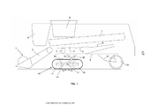
[007] A Figura 1 mostra uma imagem esquemática de uma colheitadeira combinada equipada com unidades de esteira planas, conforme conhecido na técnica.[007] Figure 1 shows a schematic image of a combine harvester equipped with flat track units, as known in the art.
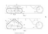
[008] A Figura 2 ilustra o chassi e as unidades de esteira planas de uma colheitadeira de acordo com uma realização da invenção.[008] Figure 2 illustrates the chassis and flat track units of a combine harvester according to an embodiment of the invention.
[009] A Figura 3 ilustra o chassi e unidades de esteira triangulares de uma colheitadeira de acordo com uma realização da invenção.[009] Figure 3 illustrates the chassis and triangular track units of a combine harvester according to an embodiment of the invention.
[010] As Figuras 4a e 4b ilustram uma realização em que o chassi inteiro pode ser elevado a uma determinada distância.[010] Figures 4a and 4b illustrate an embodiment in which the entire chassis can be lifted a certain distance.
[011] A Figura 5 ilustra o chassi e um meio de engate ao solo sem esteira em uma colheitadeira de acordo com a invenção.[011] Figure 5 illustrates the chassis and a means of coupling to the ground without a track in a combine according to the invention.
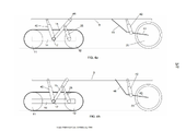
[012] As Figuras 6a e 6b ilustram configurações alternativas dos locais de montagem e o número de atuadores em uma colheitadeira de acordo com a invenção.[012] Figures 6a and 6b illustrate alternative configurations of mounting locations and the number of actuators in a combine according to the invention.
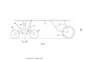
[013] As Figuras 7a e 7b ilustram uma colheitadeira de acordo com a invenção equipada com um arranjo de limpeza que tem uma largura funcional que é maior do que a distância entre as duas unidades de esteira frontais da colheitadeira.[013] Figures 7a and 7b illustrate a combine according to the invention equipped with a cleaning arrangement that has a working width that is greater than the distance between the two front track units of the combine.
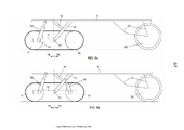
[014] As Figuras 8a e 8b mostram duas realizações adicionais que envolvem unidades de esteira triangulares, de acordo com a invenção.[014] Figures 8a and 8b show two additional embodiments involving triangular conveyor units, in accordance with the invention.
[015] As realizações da invenção serão agora descritas com referência às Figuras. A descrição detalhada não limita o escopo da invenção, a qual é definida apenas pelas reivindicações anexas. As noções de “dianteiro”, “traseiro”, “em frente a” e "atrás” usadas nessa descrição e nas reivindicações devem ser compreendidas em relação à direção longitudinal da colheitadeira, isto é, a direção entre o bico e a cauda da colheitadeira, sendo que o bico define a dianteira e a cauda define a traseira.[015] Embodiments of the invention will now be described with reference to the Figures. The detailed description does not limit the scope of the invention, which is defined only by the appended claims. The notions of “front”, “rear”, “in front of” and “behind” used in this description and in the claims must be understood in relation to the longitudinal direction of the combine, i.e. the direction between the nose and tail of the combine , with the beak defining the front and the tail defining the rear.
[016] A invenção é explicada em relação a inúmeras figuras esquemáticas. A Figura 1 mostra os principais componentes de uma colheitadeira combinada conforme conhecido no estado da técnica, equipada com um par de unidades de esteira planas 10 na frente. As colheitas são cortadas do campo pelo conjunto de plataforma 1, e supridas pelo alimentador 2 a um par de rotores de debulha e separação 3, dispostos ao longo da direção longitudinal da colheitadeira. A cabine do motorista 4 é indicada, assim como o arranjo de limpeza, que compreende um recipiente de preparação alternado 5, acoplado a tamises alternados 6, e um soprador 7 para soprar material de resíduo leve para trás da colheitadeira conforme o grão cai através dos tamises e é reunido em um tanque de grão 8. Atrás da colheitadeira (não mostrada), meios fragmentador e espalhador são montados para fragmentar os talos e folhas maiores transportados para lá pelos rotores, assim como o resíduo mais leve que permanece nos tamises 6 ou é soprado de volta ao soprador 7.[016] The invention is explained in relation to numerous schematic figures. Figure 1 shows the main components of a combine harvester as known in the prior art, equipped with a pair of
[017] As unidades de esteira planas 10 compreendem rodas-guia 11 e 12 em torno das quais uma esteira de borracha 13 é disposta para girar. As rodas de truque estão normalmente presentes, mas não são mostradas por razão de simplicidade das Figuras. Uma dentre as rodas-guia é conectada à fonte de potência da colheitadeira por um mecanismo de acionamento adequado (não mostrado). As rodas-guia são montadas em uma moldura de unidade de esteira que é esquematicamente ilustrada como uma viga 14, apesar de que, na realidade, a mesma é obviamente mais complexa e pode, por exemplo, compreender meios de amortecimento e/ou tensionamento conforme conhecidos como tais na técnica. A moldura de unidade de esteira 14 é montada no chassi da colheitadeira 9 através de uma estrutura de sustentação, ilustrada pelas vigas de sustentação 15/16, as quais são fixadas ao chassi da colheitadeira. A moldura de unidade de esteira 14 é giratória em torno de um eixo geométrico transversal 17 em relação à estrutura de sustentação 15/16 e, desse modo, em relação ao chassi 9. O eixo geométrico transversal 17 está situado entre uma porção dianteira e traseira 18 e 19 da unidade de esteira, de modo que as porções dianteira e traseira possam ser inclinadas para cima ou para baixo pelo movimento de pivotação da unidade de esteira para, desse modo, adaptar ao desnivelamento do terreno e para manter o chassi estável apesar de tal desnivelamento. Atrás da colheitadeira, um par de rodas 20 é fornecido, montado no chassi por uma estrutura de sustentação adequada 21 (incluindo amortecedores, etc.), conforme conhecido como tal na técnica.[017] The
[018] Conforme explicado no parágrafo introdutório, a capacidade da unidade de esteira para girar em torno do eixo geométrico transversal 17 é instrumental para permitir que a esteira siga o desnivelamento do terreno, mas a mesma pode ser responsável também por fazer com que a colheitadeira emperre por uma inclinação excessiva para frente das unidades de esteira as quais fazem com que as unidades se escondam dentro do terreno. A inclinação excessiva para frente da porção dianteira 18 das unidades de esteira tem menor probabilidade de ocorrer em campos suficientemente planos, mas podem, no entanto, ser um problema em campos muito desnivelados. Para solucionar esses problemas, a colheitadeira da invenção é equipada com um meio para conter uma inclinação excessiva para baixo e/ou para cima da porção dianteira 18 das unidades de esteira. A Figura 2 ilustra a operação de uma unidade de esteira plana 10' em uma colheitadeira de acordo com a invenção. Um atuador de comprimento variável 25 é montado entre a viga de sustentação 15 e um ponto 26 da moldura da unidade de esteira 14, sendo que o último ponto se localiza atrás do eixo geométrico transversal 17. Conforme a viga de sustentação 15 é conectada de modo imóvel ao chassi, o atuador é, portanto, acoplado de modo eficaz entre o chassi 9 e a unidade de esteira 10'.[018] As explained in the introductory paragraph, the ability of the track unit to rotate around the transverse
[019] O atuador 25 pode ser um atuador do tipo pistão/cilindro pneumático ou hidráulico conforme conhecido como tal na técnica. Os pontos de extremidade do atuador 25 são montados de modo giratório nos pontos 26 e 27 da moldura da unidade de esteira 14 e da viga de sustentação 15, respectivamente. A atuação do atuador 25 pode ocorrer na forma de uma extensão forçada do comprimento do atuador, empurrando-se a porção traseira 19 da unidade de esteira para baixo em relação ao chassi, de modo que a porção dianteira 18 da unidade de esteira seja inclinada para cima. Essa contenção de uma posição de inclinação para baixo excessiva da porção dianteira da unidade de esteira 18 pode ser aplicada, por exemplo, manualmente ativada a partir da cabine do motorista 4, a qualquer momento em que a colheitadeira fique emperrada da maneira descrita acima. O atuador 25 pode operar igualmente de uma maneira automática, isto é, aplicando-se uma contenção sempre que a inclinação para baixo da porção dianteira da unidade de esteira 18 exceder um valor predefinido. Isso pode ser detectado por qualquer arranjo de sensor adequado, por exemplo, um sensor de movimento giratório posicionado nos eixos geométricos de pivô 17 da unidade de esteira. Como uma alternativa ou adicionalmente a tal medição direta da posição de inclinação das unidades de esteira, o tipo de terreno em que uma inclinação excessiva para frente das unidades de esteira tem probabilidade de ocorrer pode ser detectado antes que tal inclinação para frente realmente aconteça, por exemplo, monitorando-se a pressão nos atuadores de elevação 22 (esquematicamente mostrados na Figura 1) configurados para elevar e posicionar o conjunto de plataforma 1 em relação ao solo. Esses atuadores são também atuadores do tipo pistão/cilindro e são conhecidos como tais nas colheitadeiras atuais. Durante a colheita, uma área de terreno lamacento em que as unidades de esteira da colheitadeira estão em perigo de ficarem emperradas pode ser detectada por uma queda de pressão significativa em uma das câmaras de pistão desses atuadores. Tal queda de pressão pode ser usada como um acionador para ativar os atuadores 25 nas unidades de esteira.[019] The
[020] De acordo com ainda outra realização, a medição da pressão nos próprios atuadores 25 (ou seus equivalentes mostrados em realizações adicionais descritas doravante no presente documento) é usada como um indicador muito rápido, detectável assim que a unidade de esteira começa a se engatar a uma área instável na qual a unidade tem probabilidade de ficar emperrada inclinando-se excessivamente para frente. Essa é outra forma de ativar os atuadores 25 mesmo antes da inclinação excessiva para frente ocorrer.[020] According to yet another embodiment, the pressure measurement in the
[021] De acordo com outra realização, é feita uma medição do ângulo de obliquidade da colheitadeira na direção longitudinal, isto é, medição do ângulo de um declive para cima ou para baixo em que a colheitadeira está subindo ou descendo, e o resultado é usado como uma entrada para ativar os atuadores 25 (ou qualquer equivalente descrito doravante no presente documento) para, desse modo, controlar a inclinação das unidades de esteira como uma função da obliquidade da colheitadeira. Em um declive para baixo, pode ser aplicada uma inclinação para cima da porção dianteira da unidade de esteira 18 maior em relação ao chassi do que em um declive para cima. Portanto, essa realização exige um sensor para medir o ângulo de obliquidade da colheitadeira como um todo (esse tipo de sensor é conhecido e aplicado nas colheitadeiras atuais), e um sensor que mede a inclinação das unidades de esteira em relação ao chassi (por exemplo, um sensor de rotação no eixo geométrico de pivô). O “ângulo de inclinação das unidades de esteira em relação ao chassi” é medido em relação a uma posição de referência, preferencialmente, a posição “horizontal” da colheitadeira, isto é, a posição quando a colheitadeira está em uma superfície horizontal plana com os atuadores 25 em um estado inativo. Os atuadores 25 são controlados, preferencialmente, de modo que a porção dianteira da unidade de esteira 18 seja constantemente inclinada para cima, sendo que o ângulo de inclinação em relação ao chassi está, por exemplo, entre 0,5 e 1 grau, dependendo do ângulo de declive e da direção de acionamento. Portanto, mesmo em uma superfície horizontal plana, as unidades de esteira são, então, constantemente inclinadas ligeiramente para cima, o que é benéfico para evitar que as esteiras fiquem emperrados.[021] According to another embodiment, a measurement of the angle of obliquity of the combine in the longitudinal direction is made, that is, measurement of the angle of an upward or downward slope in which the combine is going up or down, and the result is used as an input to activate the actuators 25 (or any equivalent described hereinafter) to thereby control the inclination of the track units as a function of the obliquity of the combine. On a downward slope, a greater upward slope of the forward portion of the
[022] A Figura 3 mostra uma colheitadeira equipada com um par de unidades de esteira do tipo triangular 30, sendo que cada unidade é dotada de uma roda-guia dianteira e traseira 31 e 32 e uma roda-guia central 33 para acionar uma esteira de borracha 29. A roda-guia central 33 é acionada pela fonte de potência da colheitadeira através de um mecanismo de acionamento adequado (não mostrado). A unidade de esteira é giratória em torno do eixo geométrico de rotação 34 da roda de acionamento 33, de modo que as porções dianteira e traseira 18/19 da unidade possa ser inclinada para cima e para baixo, como no caso da unidade de esteira plana da Figura 2. Um atuador 35 é novamente montado entre o chassi da colheitadeira 9 e um ponto 36 na moldura de unidade de esteira 37. O ponto de conexão 36 se localiza atrás do eixo geométrico de pivô 34 da unidade de esteira. A função do atuador 35 é a mesma que a função do atuador 25 na realização da Figura 2.[022] Figure 3 shows a combine equipped with a pair of triangular-
[023] De acordo com uma realização, os atuadores 25 ou 35 podem ser parte de um mecanismo de elevação e/ou nivelamento configurado para elevar o chassi 9 inteiro da colheitadeira combinada e/ou nivelar o chassi elevando-se a porção dianteira ou traseira do chassi separadamente. Essa realização é ilustrada nas Figuras 4a e 4b para o caso de uma colheitadeira equipada com unidades de esteira planas 10'. Um atuador de elevação 40 é montado entre o eixo geométrico de pivô 17 e o chassi 9. A viga de sustentação 15 é agora giratória em relação ao chassi 9 em seu ponto de fixação 41. Atrás da colheitadeira, os atuadores 42 são montados entre o chassi e as vigas 43 que carregam os eixos geométricos traseiros das rodas 20. A viga de sustentação 44 é giratória em ambas as extremidades. Em um sistema de nivelamento, os atuadores de elevação 40 e 42 podem ser operados separadamente.[023] According to one embodiment, the
[024] O desenho na Figura 4b mostra o chassi em uma posição elevada em relação à posição mostrada na Figura 4a. É claramente visível como o conjunto de atuadores e vigas giratórias trabalha como um mecanismo de elevação para o chassi. Em cada altura do chassi, os atuadores 25 (um em cada unidade de esteira) retêm suas funções de estabelecimento da unidade de esteira ao conter uma inclinação excessiva para frente da unidade de esteira 10'.[024] The drawing in Figure 4b shows the chassis in an elevated position compared to the position shown in Figure 4a. It is clearly visible how the set of actuators and rotating beams work as a lifting mechanism for the chassis. At each chassis height, actuators 25 (one on each track unit) retain their track unit establishing functions by countering excessive forward tilt of track unit 10'.
[025] A Figura 5 mostra um exemplo de um meio de engate ao solo sem esteira 50 ao qual a invenção pode igualmente ser aplicada. O meio de engate ao solo nessa realização é uma moldura giratória 51 que carrega uma roda dianteira e traseira 52/53 (ou preferencialmente um par dianteiro de rodas disposto em eixos geométricos na frente da moldura 51 e um par traseiro de rodas disposto em eixos geométricos na traseira da moldura 51). Um atuador 54 é novamente montado entre o chassi 9 e um ponto 56 localizado atrás do eixo geométrico de pivô 55.[025] Figure 5 shows an example of a matless ground engagement means 50 to which the invention can also be applied. The ground engaging means in that embodiment is a
[026] Em uma variação em qualquer das realizações descritas acima, ilustradas na Figura 6a, um atuador de comprimento variável 60 pode ser montado entre o chassi 9 e um ponto 61 da moldura 14 localizado em frente ao eixo geométrico de pivô lateral 17, sendo que o atuador 60 é configurado para exercer uma força de tração na porção dianteira 18 do meio de engate ao solo para, desse modo, conter a inclinação excessiva para frente descrita acima do meio de engate ao solo. De acordo com outra realização, ilustrada na Figura 6b, dois atuadores 60 e 25 podem ser montados entre o chassi 9 e as porções dianteira e traseira 18/19 do meio de engate ao solo, respectivamente. Então, os atuadores 60/25 são configurados para cooperar na contenção da inclinação excessiva para frente do meio de engate ao solo descrita acima.[026] In a variation on any of the embodiments described above, illustrated in Figure 6a, an actuator of
[027] De acordo com uma realização em que o atuador é parte de um sistema de elevação e/ou nivelamento para o chassi inteiro, a largura funcional W do arranjo de limpeza é mais larga do que a distância entre as unidades de esteira dianteiras 10', e o arranjo de limpeza 65 se estende lateralmente acima das unidades de esteira, consulte a Figura 7. A largura funcional W é definida como a largura do recipiente de limpeza 5 e/ou dos tamises 6, aquela que for maior (se houver). Então, a colheitadeira pode ser operada em um modo “baixo” e modo “alto” definido por uma posição retraída e uma estendida do mecanismo de elevação. No modo baixo (Figura 7a), a colheitadeira é adaptada para se deslocar em estradas endurecidas tais como vias públicas, nas quais a conformidade com as limitações de altura do veículo é exigida. A redução da distância entre o arranjo de limpeza 65 e as unidades de esteira 10' não é um problema visto que em terreno plano as unidades de esteira não são submetidas a grandes movimentos de inclinação. No modo alto, a colheitadeira é adaptada para operação de campo. As esteiras são permitidas mais espaço para inclinação de modo a se adaptar ao desnivelamento mais importante do terreno em comparação com estradas planas. No campo, a colheitadeira geralmente se move mais lenta e não é submetida às regulações de altura que existem nas vias públicas. O arranjo de limpeza amplo 65 permite um aumento na capacidade de grãos em comparação com colheitadeiras que têm um arranjo de limpeza que é encaixado entre as rodas frontais ou esteiras, conforme acontece no caso das colheitadeiras combinadas conhecidas atualmente.[027] According to an embodiment in which the actuator is part of a lifting and/or leveling system for the entire chassis, the functional width W of the cleaning arrangement is wider than the distance between the front track units 10 ', and the
[028] A Figura 8 mostra outras duas realizações que envolvem unidades de esteira em formato triangular. Na realização da Figura 8a, o eixo geométrico de pivô da unidade de esteira não coincide com o eixo geométrico de rotação 34 da roda-guia central 33. A unidade de esteira é giratória em torno de um eixo geométrico 38 localizado abaixo do eixo geométrico de rotação 34, em uma viga horizontal 39 que é fixada ao chassi da colheitadeira em pontos de conexão 70 e 71, pontos nos quais a viga 39 é fixada a uma estrutura vertical 72 que é parte do chassi 9. A moldura 37 da unidade de esteira é fixada de modo giratório à viga 39 no eixo geométrico de pivô 38. Novamente, o local do eixo geométrico de pivô define uma porção dianteira e traseira 18/19 da unidade de esteira. Um atuador de comprimento variável 73 é montado entre a porção traseira da viga 39 (isto é, a porção atrás do eixo geométrico de pivô) e um ponto 74 na moldura da unidade de esteira moldura 37, sendo que o ponto 74 se localiza atrás do eixo geométrico de pivô 38. O atuador 73 tem a mesma função como nas realizações prévias, de atuar o movimento de pivotação da unidade de esteira empurrando-se para baixo ou empurrando-se para cima a porção traseira 19 da unidade de esteira em relação à viga 39 e, portanto, em relação ao chassi 9. Como uma alternativa, o atuador 73 pode ser montado entre a porção dianteira da viga 39 e a porção dianteira da moldura da unidade de esteira 37, ou dois atuadores podem ser montados em qualquer dos lados do eixo geométrico de pivô 38, entre a viga 39 e a moldura da unidade de esteira 37.[028] Figure 8 shows two other embodiments involving triangular mat units. In the embodiment of Figure 8a, the track unit pivot axis does not coincide with the
[029] A Figura 8b mostra uma realização em que o mesmo tipo de unidade de esteira triangular que aquele mostrado na Figura 8a é dotado de um atuador de comprimento variável 80 conectado entre a moldura da unidade de esteira 37 (ponto 74 localizado atrás do eixo geométrico de pivô 38) e um ponto 81 no chassi 9 que não se localiza na viga horizontal 39. Essa realização é similar às realizações da Figura 3, exceto pelo fato de a unidade de esteira ser giratória em torno de um eixo geométrico 38 que é diferente do eixo geométrico de rotação 34 da roda de acionamento.[029] Figure 8b shows an embodiment in which the same type of triangular mat unit as that shown in Figure 8a is provided with a
[030] Na descrição acima, a ênfase foi feita em relação à contenção de uma inclinação excessiva para frente das unidades de esteira por um atuador de comprimento variável, empurrando-se para baixo a porção traseira da unidade de esteira 19 (atuadores 25, 35, 54, 73, 80) ou empurrando- se para cima a porção dianteira da unidade de esteira 18 em relação ao chassi da colheitadeira (atuador 60). Contudo, é evidente que os atuadores de comprimento variável 25, 35, 54, 60, 73, 80 descritos para esse propósito podem ter capacidade também de atuar o movimento inverso, isto é, empurrar para baixo a porção dianteira 18 (atuadores 25, 35, 54, 73, 80) ou empurrar para cima a porção traseira 19 (atuador 60) para, desse modo, conter uma inclinação excessiva para cima das unidades de esteira. Com a maioria dos tipos de atuadores pneumáticos ou hidráulicos, a atuação é possível na direção para cima assim como para baixo, de modo que, a inclinação para cima assim como para baixo podem ser ativamente controladas. Contudo, é possível usar também um atuador com capacidade apenas de atuar em uma direção (em direção ou para longe do chassi) ou uma combinação de vários tipos de atuador. Em qualquer das realizações descritas acima, o fato de que os atuadores 25, 35, 54, 60, 73 e 80 são mostrados como atuadores de pistão/cilindro não impede a possibilidade de que na prática diversos atuadores sejam usados para juntos realizar as funções descritas acima.[030] In the above description, emphasis was placed on the containment of excessive forward tilt of the track units by an actuator of variable length, pushing down the rear portion of the track unit 19 (
[031] É observado adicionalmente que um atuador de comprimento variável aplicável em uma colheitadeira de acordo com a invenção não se limita a um atuador pneumático ou hidráulico, mas pode incluir qualquer aparelho com capacidade para exercer uma força na porção dianteira e/ou traseira 18/19 de uma unidade de esteira, sendo que a dita força empurra a dita porção para longe do chassi da colheitadeira ou empurra a mesma em direção ao chassi.[031] It is further noted that an actuator of variable length applicable in a harvester according to the invention is not limited to a pneumatic or hydraulic actuator, but can include any device capable of exerting a force in the front and/or
[032] A invenção também se refere a métodos para operar uma colheitadeira combinada de acordo com a invenção, equipada com meios de engate ao solo do tipo de unidade de esteira ou equivalente ao mesmo, os quais são dotados de atuadores configurados para atuar a inclinação para cima e/ou para baixo da porção dianteira do meio de engate ao solo em relação ao chassi da colheitadeira. Preferencialmente, os atuadores são operáveis manualmente a partir da cabine da colheitadeira, de modo que o motorista tenha capacidade para ativar os atuadores e controlar o grau de ativação sempre que as unidades de esteira forem submetidas à inclinação excessiva. Com base nas medições de sensor, o método pode ser descrito em termos de um procedimento de controle automático que pode permanecer ainda, preferencialmente, combinado com a operação manual dos atuadores. Quando é fornecido um arranjo de sensor que mede um parâmetro que é igual ou diretamente relacionado ao ângulo de inclinação real da unidade de esteira, o método pode compreender as etapas de: • medir o parâmetro, • determinar a inclinação para baixo ou para cima da porção dianteira 18 do meio de engate ao solo, • comparar a inclinação para baixo ou para cima a um valor predefinido, • conter a inclinação para baixo ou para cima ativando-se os atuadores (25, 35, 54, 60, 73, 80). Possivelmente, a força exigida para a contenção pode ser calculada antes de ativar o atuador.[032] The invention also relates to methods for operating a combine harvester according to the invention, equipped with means of engagement to the ground of the track unit type or equivalent thereof, which are provided with actuators configured to actuate the inclination up and/or down the front portion of the ground hook relative to the combine frame. Preferably, the actuators are manually operable from the cab of the combine so that the driver has the ability to activate the actuators and control the degree of activation whenever the track units are subjected to excessive tilting. On the basis of the sensor measurements, the method can be described in terms of an automatic control procedure that can still preferably be combined with the manual operation of the actuators. Where a sensor array is provided that measures a parameter that is equal to or directly related to the actual incline angle of the treadmill unit, the method may comprise the steps of: • measuring the parameter, • determining the down or up incline of the
[033] Quando é fornecido um sensor que prevê a inclinação para baixo ou para cima antes de a mesma realmente ocorrer, tal como um sensor de pressão nos atuadores de elevação de plataforma ou nos próprios atuadores 25/35/54/60, o método pode compreender as etapas de: • detectar uma área no terreno em que a inclinação excessiva para baixo ou para cima tem maior probabilidade de ocorrer, por exemplo, detectandose uma queda de pressão nos atuadores de elevação de plataforma, sendo que a queda de pressão excede um valor de referência predefinido, • ativar os atuadores (25, 35, 54, 60, 73, 80) de uma maneira precavida, para conter a inclinação excessiva para baixo ou para cima assim que a mesma ocorrer.[033] When a sensor is provided that predicts the slope down or up before it actually occurs, such as a pressure sensor in the platform elevation actuators or in the 25/35/54/60 actuators themselves, the method may comprise the steps of: • detecting an area on the ground where excessive downward or upward tilt is more likely to occur, for example, detecting a pressure drop across the platform lift actuators where the pressure drop exceeds a preset reference value, • activate the actuators (25, 35, 54, 60, 73, 80) in a precautionary manner, to contain the excessive downward or upward tilt as soon as it occurs.
[034] De acordo com uma realização, o método da invenção monitora a obliquidade longitudinal da colheitadeira como um todo e mantém o ângulo de inclinação do meio de engate ao solo em um valor que é uma função predefinida do ângulo de obliquidade ou em um ângulo que está em uma faixa de valores, sendo que a dita faixa tem uma relação predefinida com o ângulo de obliquidade. Esse método pode compreender as etapas de: • medir a obliquidade longitudinal da colheitadeira, • determinar a partir da dita medição um valor desejado do ângulo de inclinação do meio de engate ao solo em relação ao chassi da colheitadeira, • medir o ângulo de inclinação do meio de engate ao solo em relação ao chassi da colheitadeira, • se os valores medido e desejado forem diferentes, atuar os atuadores (25, 35, 54, 60, 73, 80) até que o valor desejado seja alcançado.[034] According to one embodiment, the method of the invention monitors the longitudinal obliquity of the combine as a whole and maintains the angle of inclination of the coupling means to the ground at a value that is a predefined function of the obliquity angle or at an angle which is in a range of values, said range having a predefined relationship with the angle of obliquity. This method may comprise the steps of: • measuring the longitudinal obliquity of the combine, • determining from said measurement a desired value of the angle of inclination of the coupling means to the ground in relation to the chassis of the combine, • measuring the angle of inclination of the means of coupling to the ground in relation to the chassis of the harvester, • if the measured and desired values are different, actuate the actuators (25, 35, 54, 60, 73, 80) until the desired value is reached.
[035] Esses métodos podem ser aplicados juntos em uma colheitadeira equipada com diversos tipos de sensores (medir inclinação e prever inclinação excessiva, medir obliquidade da colheitadeira). Esses métodos podem ser aplicados como rotinas de software implantadas na colheitadeira.[035] These methods can be applied together in a combine equipped with several types of sensors (measure slope and predict excessive slope, measure harvester obliquity). These methods can be applied as software routines implemented in the combine.
Claims (17)
Applications Claiming Priority (3)
| Application Number | Priority Date | Filing Date | Title |
|---|---|---|---|
| BE2014/0030 | 2014-01-21 | ||
| BE2014/0030A BE1022418B1 (en) | 2014-01-21 | 2014-01-21 | CUTTING DISHER WITH CATERPILLAR UNITS EQUIPPED WITH ACTUATORS THAT TAKE AGAINST TIP |
| PCT/EP2015/050836 WO2015110373A1 (en) | 2014-01-21 | 2015-01-19 | Combine harvester with track units equipped with tilt-counteracting actuators |
Publications (2)
| Publication Number | Publication Date |
|---|---|
| BR112016016558A2 BR112016016558A2 (en) | 2017-08-08 |
| BR112016016558B1 true BR112016016558B1 (en) | 2022-11-16 |
Family
ID=50272207
Family Applications (1)
| Application Number | Title | Priority Date | Filing Date |
|---|---|---|---|
| BR112016016558-6A BR112016016558B1 (en) | 2014-01-21 | 2015-01-19 | COMBINED HARVESTER AND ITS OPERATION METHOD |
Country Status (5)
| Country | Link |
|---|---|
| US (1) | US10065691B2 (en) |
| EP (1) | EP3097002B1 (en) |
| BE (1) | BE1022418B1 (en) |
| BR (1) | BR112016016558B1 (en) |
| WO (1) | WO2015110373A1 (en) |
Families Citing this family (16)
| Publication number | Priority date | Publication date | Assignee | Title |
|---|---|---|---|---|
| US10864954B2 (en) * | 2015-11-03 | 2020-12-15 | Camso Inc. | Track system for traction of a vehicle |
| WO2018119350A1 (en) * | 2016-12-22 | 2018-06-28 | Superior Industries, Inc. | Plant chassis leveling apparatus, systems and methods |
| SE542243C2 (en) * | 2017-03-17 | 2020-03-24 | Komatsu Forest Ab | Suspension device for tracked vehicles |
| JP6861106B2 (en) * | 2017-06-21 | 2021-04-21 | ヤンマーパワーテクノロジー株式会社 | Green onion harvester |
| WO2019046929A1 (en) * | 2017-09-08 | 2019-03-14 | Camso Inc. | System and method for controlling a track system for traction of a vehicle |
| US10375890B2 (en) | 2017-10-30 | 2019-08-13 | Deere & Company | Level control method for an agricultural combine |
| IT201800002803A1 (en) * | 2018-02-19 | 2019-08-19 | Green Tech Innovation Srl | SELF PROPELLED VEHICLE |
| US20190317497A1 (en) * | 2018-04-13 | 2019-10-17 | Bedestrian LLC | Autonomous vehicle |
| US11008055B2 (en) | 2018-11-20 | 2021-05-18 | Deere & Company | Track management system for use with a work machine and track assembly |
| SE542937C2 (en) * | 2018-12-21 | 2020-09-15 | Eco Log Sweden Ab | Forestry vehicle comprising idler wheel and drive wheel arranged on a pivotable arm |
| DE102019104953A1 (en) | 2019-02-27 | 2020-08-27 | Claas Selbstfahrende Erntemaschinen Gmbh | Harvesting machine and method for harvesting using a harvesting machine |
| CN110042706A (en) * | 2019-05-29 | 2019-07-23 | 昆明学院 | Ballast moves flat jolt ramming automation equipment between a kind of sleeper |
| CN110029542A (en) * | 2019-05-29 | 2019-07-19 | 昆明学院 | A kind of chain bucket row stone multifunction automatic device |
| CN110144775A (en) * | 2019-05-29 | 2019-08-20 | 长春工程学院 | The integrated rail that mentions of one kind changes pillow multifunctional intelligent machinery |
| CN110144774A (en) * | 2019-05-29 | 2019-08-20 | 长春工程学院 | Fast quick change pillow multifunctional intelligent is mechanical |
| US20230129397A1 (en) * | 2021-10-25 | 2023-04-27 | Deere & Company | Work vehicle implement joint orientation system and method |
Family Cites Families (25)
| Publication number | Priority date | Publication date | Assignee | Title |
|---|---|---|---|---|
| US3233909A (en) | 1964-04-24 | 1966-02-08 | Allis Chalmers Mfg Co | Leveling system for hillside combines |
| GB1139090A (en) * | 1965-04-05 | 1969-01-08 | Raimo Mikael Kronqvist | Improvements relating to vehicle steering systems |
| IT984994B (en) | 1973-05-18 | 1974-11-20 | Bruni M | SELF-LEVELING DEVICE FOR LARGE AGRICULTURAL MACHINES |
| US4050704A (en) | 1975-09-08 | 1977-09-27 | Institutul De Cercetari Si Proiectari De Masini Agricole-Icpma | Device for maintaining an upright position of the body of a harvester-thresher machines |
| US4247126A (en) | 1979-09-27 | 1981-01-27 | Up-Right, Inc. | Hydraulic suspension for harvesting machines |
| DE3420233A1 (en) | 1984-05-30 | 1985-12-05 | Helwig Dipl.-Ing. 3523 Grebenstein Schmitt | Combine harvester |
| US4750751A (en) | 1986-11-26 | 1988-06-14 | Deere & Company | Pivoting axle for a hillside combine |
| US5178402A (en) | 1991-08-07 | 1993-01-12 | Deere & Company | Leveling assembly for a vehicle |
| DE4415689A1 (en) | 1994-05-04 | 1995-11-09 | Claas Ohg | Crawler chassis for harvesters |
| JP3090607B2 (en) | 1996-02-07 | 2000-09-25 | 井関農機株式会社 | Tilt control device in combine |
| US5839954A (en) * | 1996-10-23 | 1998-11-24 | Byron Enterprises Inc. | Sweet corn processing system |
| US6158203A (en) * | 1999-01-06 | 2000-12-12 | Scott; Phillip Ray | Over the row tractor and crop harvester |
| JP2001000032A (en) | 1999-06-17 | 2001-01-09 | Seirei Ind Co Ltd | Apparatus for controlling vehicle height of combine during turning |
| JP2001000031A (en) | 1999-06-17 | 2001-01-09 | Seirei Ind Co Ltd | Apparatus for controlling vehicle height of combine during turning |
| DE10000145C2 (en) | 2000-01-04 | 2003-05-28 | Claas Industrietechnik Gmbh | Agricultural work machine |
| JP4680355B2 (en) | 2000-08-10 | 2011-05-11 | ヤンマー株式会社 | Combine |
| US6892838B2 (en) * | 2002-03-08 | 2005-05-17 | Honda Giken Kogyo Kabushiki Kaisha | Stabilizer bar for independently suspended beam structure |
| ES2257130B1 (en) | 2003-10-08 | 2007-07-16 | Angel Carlos Irujo Lopez | LEVELING-COMPENSATOR SYSTEM FOR HARVESTING AND SIMILAR MACHINES. |
| US8180532B2 (en) | 2006-05-26 | 2012-05-15 | Deere & Company | Vector controlled leveling system for a forestry machine |
| AT9639U1 (en) * | 2006-12-22 | 2008-01-15 | Georg Jeitler | tracked vehicle |
| ITMN20080012A1 (en) | 2008-06-05 | 2009-12-06 | Tidue S R L | TRACKING MACHINE FOR WORKING MACHINE ON SOIL |
| DE102010036756A1 (en) | 2010-07-30 | 2012-02-02 | Claas Selbstfahrende Erntemaschinen Gmbh | Self-propelled harvester |
| US8849556B2 (en) * | 2011-10-28 | 2014-09-30 | Papé Machinery | Automatic leveling control |
| CH707606A1 (en) | 2013-02-05 | 2014-08-15 | Studersond Ag | Vehicle. |
| US9409459B2 (en) * | 2013-07-19 | 2016-08-09 | Papé Machinery, Inc. | 4-way leveling |
-
2014
- 2014-01-21 BE BE2014/0030A patent/BE1022418B1/en active
-
2015
- 2015-01-19 BR BR112016016558-6A patent/BR112016016558B1/en active IP Right Grant
- 2015-01-19 EP EP15700486.2A patent/EP3097002B1/en active Active
- 2015-01-19 US US15/112,651 patent/US10065691B2/en active Active
- 2015-01-19 WO PCT/EP2015/050836 patent/WO2015110373A1/en active Application Filing
Also Published As
| Publication number | Publication date |
|---|---|
| WO2015110373A1 (en) | 2015-07-30 |
| US10065691B2 (en) | 2018-09-04 |
| EP3097002A1 (en) | 2016-11-30 |
| BE1022418B1 (en) | 2016-03-25 |
| US20160332681A1 (en) | 2016-11-17 |
| EP3097002B1 (en) | 2020-04-29 |
| BR112016016558A2 (en) | 2017-08-08 |
Similar Documents
| Publication | Publication Date | Title |
|---|---|---|
| BR112016016558B1 (en) | COMBINED HARVESTER AND ITS OPERATION METHOD | |
| BR112019024053A2 (en) | PLATFORM AND FEEDER POSITIONING METHOD | |
| BR102019008303A2 (en) | HARVESTING HEAD FOR A COMBINATION, AND, METHOD FOR OPERATING A COMBINATION WITH A HARVESTING HEAD | |
| BRPI1004114A2 (en) | farm harvester, and spike height control system | |
| CA3047950A1 (en) | A cutting unit for an agricultural working machine and a method for adjusting a cutting unit | |
| WO2020004024A1 (en) | Working vehicle | |
| GB2208581A (en) | Crop lifters | |
| KR20100050327A (en) | Root-harverster with digging level adjuster | |
| JP2004276671A (en) | Working machine | |
| JP5641096B2 (en) | Seedling transplanter | |
| JP2556136B2 (en) | Combine operation device | |
| PL226241B1 (en) | Full-row berry fruit harvester | |
| JP2943262B2 (en) | Attitude control device such as combine | |
| JP3191375B2 (en) | Combine harvesting elevating sensor | |
| BR102018068365A2 (en) | METHOD FOR CONTROLLING AN ANGULAR ORIENTATION OF AN AGRICULTURAL COMBINATION | |
| JP2985262B2 (en) | Pitching control device for mobile farm machine | |
| JP2000000015A (en) | Combine harvester | |
| AU1652499A (en) | Self-levelling mobile supporting chassis | |
| BR102018068365B1 (en) | METHOD FOR CONTROLLING AN ANGULAR ORIENTATION OF AN AGRICULTURAL COMBINATION | |
| JPH0233631Y2 (en) | ||
| BR102018075938A2 (en) | HARVEST | |
| AU718169B3 (en) | Self-levelling mobile supporting chassis | |
| JPH1132556A (en) | Rolling controller of combine harvester | |
| JPH10215644A (en) | Rolling controller for combine harvester | |
| JP4901667B2 (en) | Work vehicle attitude control device |
Legal Events
| Date | Code | Title | Description |
|---|---|---|---|
| B06U | Preliminary requirement: requests with searches performed by other patent offices: procedure suspended [chapter 6.21 patent gazette] | ||
| B09A | Decision: intention to grant [chapter 9.1 patent gazette] | ||
| B16A | Patent or certificate of addition of invention granted [chapter 16.1 patent gazette] |
Free format text: PRAZO DE VALIDADE: 20 (VINTE) ANOS CONTADOS A PARTIR DE 19/01/2015, OBSERVADAS AS CONDICOES LEGAIS |