US9409459B2 - 4-way leveling - Google Patents
4-way leveling Download PDFInfo
- Publication number
- US9409459B2 US9409459B2 US14/332,933 US201414332933A US9409459B2 US 9409459 B2 US9409459 B2 US 9409459B2 US 201414332933 A US201414332933 A US 201414332933A US 9409459 B2 US9409459 B2 US 9409459B2
- Authority
- US
- United States
- Prior art keywords
- leveling
- vehicle
- rocker plate
- wheel
- actuator
- Prior art date
- Legal status (The legal status is an assumption and is not a legal conclusion. Google has not performed a legal analysis and makes no representation as to the accuracy of the status listed.)
- Active
Links
- 230000008901 benefit Effects 0.000 claims description 13
- 230000004044 response Effects 0.000 claims description 12
- 230000009471 action Effects 0.000 claims description 9
- 238000009434 installation Methods 0.000 claims 1
- 238000000034 method Methods 0.000 abstract description 39
- 230000008569 process Effects 0.000 description 21
- 238000010586 diagram Methods 0.000 description 11
- 235000013339 cereals Nutrition 0.000 description 9
- 238000013461 design Methods 0.000 description 6
- 230000007423 decrease Effects 0.000 description 4
- 239000007788 liquid Substances 0.000 description 4
- 230000007935 neutral effect Effects 0.000 description 4
- 238000010276 construction Methods 0.000 description 3
- 230000003247 decreasing effect Effects 0.000 description 3
- 238000000926 separation method Methods 0.000 description 3
- 238000009412 basement excavation Methods 0.000 description 2
- 230000005540 biological transmission Effects 0.000 description 2
- 238000004891 communication Methods 0.000 description 2
- 230000000694 effects Effects 0.000 description 2
- 239000012530 fluid Substances 0.000 description 2
- 239000000463 material Substances 0.000 description 2
- 239000000725 suspension Substances 0.000 description 2
- 241000219310 Beta vulgaris subsp. vulgaris Species 0.000 description 1
- 244000056139 Brassica cretica Species 0.000 description 1
- 235000003351 Brassica cretica Nutrition 0.000 description 1
- 240000002791 Brassica napus Species 0.000 description 1
- 235000011293 Brassica napus Nutrition 0.000 description 1
- 235000000540 Brassica rapa subsp rapa Nutrition 0.000 description 1
- 235000003343 Brassica rupestris Nutrition 0.000 description 1
- 244000025254 Cannabis sativa Species 0.000 description 1
- 241000234642 Festuca Species 0.000 description 1
- 244000068988 Glycine max Species 0.000 description 1
- 235000010469 Glycine max Nutrition 0.000 description 1
- 241001124569 Lycaenidae Species 0.000 description 1
- 240000004658 Medicago sativa Species 0.000 description 1
- 235000017587 Medicago sativa ssp. sativa Nutrition 0.000 description 1
- 244000088415 Raphanus sativus Species 0.000 description 1
- 235000006140 Raphanus sativus var sativus Nutrition 0.000 description 1
- 235000004443 Ricinus communis Nutrition 0.000 description 1
- 235000021536 Sugar beet Nutrition 0.000 description 1
- 241000219793 Trifolium Species 0.000 description 1
- 235000021307 Triticum Nutrition 0.000 description 1
- 244000098338 Triticum aestivum Species 0.000 description 1
- 240000008042 Zea mays Species 0.000 description 1
- 235000005824 Zea mays ssp. parviglumis Nutrition 0.000 description 1
- 235000002017 Zea mays subsp mays Nutrition 0.000 description 1
- 238000013459 approach Methods 0.000 description 1
- 230000000712 assembly Effects 0.000 description 1
- 238000000429 assembly Methods 0.000 description 1
- QKSKPIVNLNLAAV-UHFFFAOYSA-N bis(2-chloroethyl) sulfide Chemical compound ClCCSCCCl QKSKPIVNLNLAAV-UHFFFAOYSA-N 0.000 description 1
- 238000004140 cleaning Methods 0.000 description 1
- 235000005822 corn Nutrition 0.000 description 1
- 238000009313 farming Methods 0.000 description 1
- 230000006870 function Effects 0.000 description 1
- 230000005484 gravity Effects 0.000 description 1
- 238000003306 harvesting Methods 0.000 description 1
- 238000007689 inspection Methods 0.000 description 1
- 238000012423 maintenance Methods 0.000 description 1
- 230000007246 mechanism Effects 0.000 description 1
- 230000004048 modification Effects 0.000 description 1
- 238000012986 modification Methods 0.000 description 1
- 235000010460 mustard Nutrition 0.000 description 1
- 230000003287 optical effect Effects 0.000 description 1
- 238000012545 processing Methods 0.000 description 1
- 230000008439 repair process Effects 0.000 description 1
- 238000003860 storage Methods 0.000 description 1
Images


Classifications
-
- B—PERFORMING OPERATIONS; TRANSPORTING
- B60—VEHICLES IN GENERAL
- B60G—VEHICLE SUSPENSION ARRANGEMENTS
- B60G17/00—Resilient suspensions having means for adjusting the spring or vibration-damper characteristics, for regulating the distance between a supporting surface and a sprung part of vehicle or for locking suspension during use to meet varying vehicular or surface conditions, e.g. due to speed or load
- B60G17/015—Resilient suspensions having means for adjusting the spring or vibration-damper characteristics, for regulating the distance between a supporting surface and a sprung part of vehicle or for locking suspension during use to meet varying vehicular or surface conditions, e.g. due to speed or load the regulating means comprising electric or electronic elements
-
- B—PERFORMING OPERATIONS; TRANSPORTING
- B60—VEHICLES IN GENERAL
- B60G—VEHICLE SUSPENSION ARRANGEMENTS
- B60G15/00—Resilient suspensions characterised by arrangement, location or type of combined spring and vibration damper, e.g. telescopic type
- B60G15/02—Resilient suspensions characterised by arrangement, location or type of combined spring and vibration damper, e.g. telescopic type having mechanical spring
- B60G15/06—Resilient suspensions characterised by arrangement, location or type of combined spring and vibration damper, e.g. telescopic type having mechanical spring and fluid damper
- B60G15/067—Resilient suspensions characterised by arrangement, location or type of combined spring and vibration damper, e.g. telescopic type having mechanical spring and fluid damper characterised by the mounting on the vehicle body or chassis of the spring and damper unit
-
- B—PERFORMING OPERATIONS; TRANSPORTING
- B60—VEHICLES IN GENERAL
- B60G—VEHICLE SUSPENSION ARRANGEMENTS
- B60G17/00—Resilient suspensions having means for adjusting the spring or vibration-damper characteristics, for regulating the distance between a supporting surface and a sprung part of vehicle or for locking suspension during use to meet varying vehicular or surface conditions, e.g. due to speed or load
- B60G17/015—Resilient suspensions having means for adjusting the spring or vibration-damper characteristics, for regulating the distance between a supporting surface and a sprung part of vehicle or for locking suspension during use to meet varying vehicular or surface conditions, e.g. due to speed or load the regulating means comprising electric or electronic elements
- B60G17/016—Resilient suspensions having means for adjusting the spring or vibration-damper characteristics, for regulating the distance between a supporting surface and a sprung part of vehicle or for locking suspension during use to meet varying vehicular or surface conditions, e.g. due to speed or load the regulating means comprising electric or electronic elements characterised by their responsiveness, when the vehicle is travelling, to specific motion, a specific condition, or driver input
- B60G17/0165—Resilient suspensions having means for adjusting the spring or vibration-damper characteristics, for regulating the distance between a supporting surface and a sprung part of vehicle or for locking suspension during use to meet varying vehicular or surface conditions, e.g. due to speed or load the regulating means comprising electric or electronic elements characterised by their responsiveness, when the vehicle is travelling, to specific motion, a specific condition, or driver input to an external condition, e.g. rough road surface, side wind
-
- B—PERFORMING OPERATIONS; TRANSPORTING
- B60—VEHICLES IN GENERAL
- B60G—VEHICLE SUSPENSION ARRANGEMENTS
- B60G17/00—Resilient suspensions having means for adjusting the spring or vibration-damper characteristics, for regulating the distance between a supporting surface and a sprung part of vehicle or for locking suspension during use to meet varying vehicular or surface conditions, e.g. due to speed or load
- B60G17/015—Resilient suspensions having means for adjusting the spring or vibration-damper characteristics, for regulating the distance between a supporting surface and a sprung part of vehicle or for locking suspension during use to meet varying vehicular or surface conditions, e.g. due to speed or load the regulating means comprising electric or electronic elements
- B60G17/019—Resilient suspensions having means for adjusting the spring or vibration-damper characteristics, for regulating the distance between a supporting surface and a sprung part of vehicle or for locking suspension during use to meet varying vehicular or surface conditions, e.g. due to speed or load the regulating means comprising electric or electronic elements characterised by the type of sensor or the arrangement thereof
- B60G17/01908—Acceleration or inclination sensors
-
- B—PERFORMING OPERATIONS; TRANSPORTING
- B60—VEHICLES IN GENERAL
- B60G—VEHICLE SUSPENSION ARRANGEMENTS
- B60G2202/00—Indexing codes relating to the type of spring, damper or actuator
- B60G2202/40—Type of actuator
-
- B—PERFORMING OPERATIONS; TRANSPORTING
- B60—VEHICLES IN GENERAL
- B60G—VEHICLE SUSPENSION ARRANGEMENTS
- B60G2204/00—Indexing codes related to suspensions per se or to auxiliary parts
- B60G2204/40—Auxiliary suspension parts; Adjustment of suspensions
- B60G2204/421—Pivoted lever mechanisms for mounting suspension elements, e.g. Watt linkage
-
- B—PERFORMING OPERATIONS; TRANSPORTING
- B60—VEHICLES IN GENERAL
- B60G—VEHICLE SUSPENSION ARRANGEMENTS
- B60G2300/00—Indexing codes relating to the type of vehicle
- B60G2300/07—Off-road vehicles
-
- B—PERFORMING OPERATIONS; TRANSPORTING
- B60—VEHICLES IN GENERAL
- B60G—VEHICLE SUSPENSION ARRANGEMENTS
- B60G2400/00—Indexing codes relating to detected, measured or calculated conditions or factors
- B60G2400/05—Attitude
- B60G2400/051—Angle
- B60G2400/0512—Pitch angle
-
- B—PERFORMING OPERATIONS; TRANSPORTING
- B60—VEHICLES IN GENERAL
- B60G—VEHICLE SUSPENSION ARRANGEMENTS
- B60G2500/00—Indexing codes relating to the regulated action or device
- B60G2500/30—Height or ground clearance
-
- B—PERFORMING OPERATIONS; TRANSPORTING
- B60—VEHICLES IN GENERAL
- B60G—VEHICLE SUSPENSION ARRANGEMENTS
- B60G2800/00—Indexing codes relating to the type of movement or to the condition of the vehicle and to the end result to be achieved by the control action
- B60G2800/90—System Controller type
- B60G2800/91—Suspension Control
- B60G2800/912—Attitude Control; levelling control
Definitions
- Various vehicles or implements that are configured for negotiating sloped terrain may use leveling or tilt systems to level at least a portion of the vehicle (such as an operator cabin, a grain storage bin, etc.) while traversing the sloped terrain.
- Leveling systems can cause a portion of the vehicle to be tilted to produce the leveling desired.
- one or more axles of a vehicle may be tilted, with one end of the axle extended away from the body of the vehicle while the other end of the axle is more or less fixed or is contracted toward the body of the vehicle.
- Such leveling systems often include techniques for sensing the slope of the terrain and then compensating for the slope by leveling portions of the vehicle while the vehicle is on the slope.
- leveling systems have one or more leveling sensors (e.g., clinometers, tilt meters, etc.) that use gravity, for example, for sensing the slope of terrain.
- leveling sensors e.g., clinometers, tilt meters, etc.
- Common techniques for sensing a slope include the use of accelerometers, liquid capacitive devices, electronic devices, electrolytic devices, devices that include a gas bubble in a liquid, and pendulum devices.
- the leveling systems can compensate as much as they are capable.
- a particular leveling system has a limited capability to compensate for a slope being traversed.
- different leveling system designs have different capabilities and limitations. For example, the tilting of axles, and so forth, can be constrained by the design and construction of the chassis, frame, suspension, drive train, body components, and the like, of the vehicle.
- the devices and systems illustrated in the figures are shown as having a multiplicity of components.
- Various implementations of devices and/or systems, as described herein, may include fewer components and remain within the scope of the disclosure.
- other implementations of devices and/or systems may include additional components, or various combinations of the described components, and remain within the scope of the disclosure.
- Shapes and/or dimensions of components shown in the illustrations of the figures are for example and ease of discussion, and other shapes and or dimensions may be used and remain within the scope of the disclosure, unless specified otherwise.
- FIG. 1 is a schematic of an example leveling system implemented with respect to a vehicle, in which the techniques and devices in accordance with the present disclosure may be embodied.
- FIG. 2 is a block diagram showing example detail of a leveling system, according to an implementation.
- FIG. 3 is a series of illustrations showing implementations of example leveling systems in operation. The illustrations show example responses from the leveling systems, according to an implementation.
- FIG. 4 is a profile view of an example leveling arrangement, showing some detail of the components of the leveling arrangement while in a retracted state, according to an embodiment.
- FIG. 5 is a profile view of the example leveling arrangement of FIG. 4 , showing some detail of the components of the leveling arrangement while in a neutral state, according to an embodiment.
- FIG. 6 is a profile view of the example leveling arrangement of FIG. 4 , showing some detail of the components of the leveling arrangement while in an extended state, according to an embodiment.
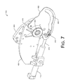
- FIG. 7 is a perspective view of an example leveling arrangement, according to an embodiment.
- FIG. 8 is another perspective view of an example leveling arrangement, according to an embodiment.
- FIG. 9 is another perspective view of an example leveling arrangement, according to an embodiment.
- FIG. 10 is another perspective view of an example leveling arrangement, according to an embodiment.
- FIG. 11 is a profile view of an example support plate of a leveling arrangement, according to an embodiment.
- FIG. 12 is a profile view of an example rocker plate of a leveling arrangement, according to an embodiment.
- FIG. 13 is a profile view of an example guide plate of a leveling arrangement, according to an embodiment.
- FIG. 14 shows example implementations of a leveling system with respect to a vehicle, according to an embodiment.
- FIG. 15 is a flow diagram illustrating an example leveling process, according to an implementation.
- Representative implementations of devices and techniques provide 4-way leveling for a vehicle, such as an overland vehicle.
- Sensors associated with the vehicle may provide signals representing one or more operating conditions of the vehicle, including forces acting on the vehicle representing a non-level condition of the vehicle, for example.
- the vehicle can be tilted or leveled based on one or more of the signals from the sensors.
- a vehicle that is traversing sloped terrain may be automatically leveled based on signals received from one or more leveling sensors configured to sense the sloped terrain.
- several or many sensors may be used to sense multiple operating conditions of a vehicle.
- the sensors may be used in various combinations to provide multiple leveling signals.
- each wheel of a vehicle may receive an independent leveling signal based on one or more of the multiple signals received from the leveling sensors.
- each wheel of the vehicle may be independently leveled (i.e., adjusted, lowered, raised, etc.) based on the vehicle receiving one or more leveling signals.
- devices and techniques for vehicle leveling are discussed in this disclosure.
- the devices and techniques are discussed with reference to example implementations illustrated in the figures.
- the devices and techniques discussed herein are referred to in the environment of an overland vehicle, such as a hillside combine harvester, for ease of discussion and illustrative convenience.
- the devices and/or techniques may also be used in other environments, with other implementations, and associated with other vehicles, systems, and the like, to provide leveling.
- vehicles and the like may have 4 or more (or less) wheels, and have various combinations of axles and suspensions.
- Advantages of the disclosed devices and techniques are varied, and include: 1) independent (4-way) leveling may occur at each wheel location; 2) greater leveling capacity and range over various types of terrain having three-dimensional slopes; 3) pitch and roll leveling provides an ability to maintain key portions of the vehicle in a level state (such as a cleaning shoe on a harvester—to optimize grain capture during separation, and also a grain tank on a harvester—saving potential losses from crop spilling); 4) greater mechanical advantage at the levelling components allows for smaller components to do greater work, or minimizes the risk of overworking the tilting mechanisms, reducing wear and energy loss; 5) maintains better traction of the vehicle and keeps proper vehicle balance; and 6) straight-forward upgrades on existing vehicles can be performed including the use of many existing components and assemblies. Other advantages of the disclosed techniques may also be present.
- FIG. 1 is a schematic of an example leveling system 102 implemented with respect to a vehicle 104 , in which the techniques and devices in accordance with the present disclosure may be embodied. It is to be understood that portions of the techniques and/or devices may be implemented as part of the vehicle 104 , as an accessory to the vehicle 104 , or as part of another system (for example as a remote system to the vehicle 104 , etc.). Further, portions of a leveling system 102 may be integrated with the vehicle 104 while other portions are remotely located.
- the vehicle 104 of the figures and the disclosure is illustrated and discussed in generic terms and often described in terms of a “hillside combine harvester” device. This is, however, for ease of discussion.
- the techniques and devices described herein with respect to leveling systems 102 is not so limited, and may be applied to other types of vehicles (e.g., farming equipment, excavation equipment, construction equipment, military vehicles, recreational vehicles, etc.) without departing from the scope of the disclosure.
- the illustrated vehicle 104 is shown as a simple vehicle having four wheels, the techniques and devices described herein are intended for implementation with vehicles having single or multiple axles, any number of wheels, and any number of steerable wheels or axles. Vehicles for overland travel are intended embodiments, as well as amphibious vehicles, and the like.
- an example leveling system 102 may be arranged to receive sensor data 106 from one or more sensors associated with a vehicle 104 .
- a vehicle 104 may be leveled by a leveling system 102 based on a first signal 202 representing a lateral force (i.e., tilt, roll) acting on the vehicle 104 and a second signal 204 representing a longitudinal force (i.e., pitch) acting on the vehicle 104 .
- the first 202 and second 204 signals may be sent by one or more vehicle sensors ( 206 , 208 ) associated with the vehicle 104 , and received by a processing or control portion 210 of the leveling system 102 , as shown in FIG. 2 .
- the leveling system 102 may use additional signals from additional sensors in combination with one or both of the first and second signals ( 202 , 204 ) and first and second sensors ( 206 , 208 ).
- the leveling system 102 may be partially or completely implemented using specialized or generic computing equipment (such as one or more processor/controllers 210 , for example) coupled to one or more local and/or remote memory devices (not shown).
- a leveling module 212 arranged to control vehicle 104 leveling may be incorporated or integrated with the processor/controller 210 , and may be stored within the one or more memory devices.
- the leveling module 212 and the processor/controller 210 may be a single unit. In other examples, the leveling module 212 may be separate from the processor/controller 210 , but may communicate with the processor/controller 210 . In one embodiment, the leveling system 102 is implemented using a CAN-based architecture. In other embodiments, the leveling system 102 may be based on other computing architectures, protocols, and/or bus systems.
- system memory e.g., memory devices
- the system memory may include stored application programs and system data.
- system memory may also include other modules, components, and the like (e.g., BIOS, controller(s), communication modules, etc.) that are used for performing the functions described herein.
- An example leveling system 102 for a vehicle 104 may include a plurality of sensors 206 , 208 coupled to the vehicle 104 .
- one or more sensors may be remote to the vehicle 104 .
- Sensors 206 , 208 may be arranged to provide information (such as sensor data 106 ) to the leveling system 102 about the operating environment of the vehicle 104 and/or the state of various vehicle 104 components and systems.
- additional or other signals may be received by the leveling system 102 , for example, to adjust or correct the leveling signals 108 , to reduce or prevent erroneous tilting of the vehicle 104 , and the like.
- the vehicle sensors 206 , 208 are clinometers (inclinometers) configured to indicate a tilt (e.g., pitch, roll, etc.) of the vehicle 104 .
- the vehicle sensors 206 , 208 may comprise one or more of an accelerometer, a gyroscope, a liquid capacitive device, an electrolytic level device, a gas bubble in liquid device, a pendulum device, and the like.
- one or more of the vehicle sensors 206 , 208 are arranged to produce a voltage proportional to a measured tilt/slope. In other embodiments, the vehicle sensors 206 , 208 are arranged to produce other types of signals, such as optical signals, magnetic signals, alternating signals, digital signals, and the like.
- the leveling system 102 may output one or more leveling signals 108 to various leveling components (e.g., leveling arrangements 402 ) of the vehicle 104 to adjust a height of an individual wheel 112 or a combination of wheels 112 with respect to the body 110 of the vehicle 104 .
- the leveling arrangements 402 may be arranged to adjust a vertical distance of a center 114 of the wheel(s) 112 from a preselected feature 116 of the body 110 or of the frame of the vehicle 104 .
- the preselected feature 116 may include features such as a mid-line of the body 110 , a top of a wheel opening of the vehicle 104 , a top of an inside wheel well, a body 110 or frame component of the vehicle 104 , and so forth.
- the preselected feature 116 is located above the center 114 of the wheel(s) 112 when the vehicle 104 is upright.
- adjusting the vertical distance of various wheel(s) 112 from the preselected feature 116 increases or decreases the ground clearance at the respective wheel(s) 112 . Adjusting the vertical distance of various wheel(s) 112 from the preselected feature 116 can level the body 110 of the vehicle 104 , notwithstanding the uneven or sloped terrain being traversed.
- individual leveling signals 108 may be output by the leveling module 212 to respective individual leveling arrangements 402 associated with individual wheels 112 of the vehicle 104 .
- a single leveling signal 108 e.g., left fore actuation, right fore actuation, left aft actuation, or right aft actuation
- a single wheel's 112 distance from the body 110 may be adjusted without any of the other wheel 112 distances from the body 110 (e.g., the preselected feature 116 ) changing.
- a combination of two or more leveling signals 108 may be sent to respective leveling arrangements 402 at respective wheels 112 to level the body 110 .
- leveling signals 108 e.g., left fore actuation, right fore actuation, left aft actuation, and right aft actuation
- the body 110 of the vehicle 104 can be uniquely leveled with respect to terrain having varying slopes.
- various leveling adjustments may be performed at individual wheels 112 by individual leveling arrangements 402 , based on the terrain 302 .
- the vehicle 104 may be on side-hill type sloped terrain 302 .
- signals 202 , 204 may be sent by the sensors 206 , 208 and received by the processor/controller 210 .
- the leveling module 212 may output one or more leveling signals 108 , in response to the sensor signals 202 , 204 received, to one or more leveling arrangements 402 to level the body 110 of the vehicle 104 .
- the leveling module 212 may send one or more of the left fore actuation, right fore actuation, left aft actuation, and right aft actuation signals 108 to leveling arrangements 402 at the respective wheel 112 locations so that the distance from one or more of the wheels 112 (e.g., center 114 ) to the preselected feature 116 on the down-hill side is increased.
- the wheels 112 e.g., center 114
- the leveling module 212 may send one or more of the left fore actuation, right fore actuation, left aft actuation, and right aft actuation signals 108 to leveling arrangements 402 at the respective wheel 112 locations so that the distance from one or more of the wheels 112 (e.g., center 114 ) to the preselected feature 116 on the up-hill side is decreased.
- the distance from one or more centers 114 of the wheels 112 to the preselected feature 116 of the body 110 has the effect of leveling the body 110 , as shown in FIG. 3 at diagram B.
- the vehicle 104 may be on longitudinally sloped terrain 302 (either uphill or downhill).
- signals 202 , 204 may be sent by the sensors 206 , 208 and received by the processor/control 210 .
- the leveling module 212 may output one or more leveling signals 108 , in response to the sensor signals 202 , 204 received, to one or more leveling arrangements 402 to level the body 110 of the vehicle 104 .
- the leveling module 212 may send one or more of the left fore actuation, right fore actuation, left aft actuation, and right aft actuation signals 108 to leveling arrangements 402 at the respective wheel 112 locations so that the distance from one or more of the wheels 112 (e.g., center 114 ) to the preselected feature 116 on the down-hill side is increased.
- the wheels 112 e.g., center 114
- the leveling module 212 may send one or more of the left fore actuation, right fore actuation, left aft actuation, and right aft actuation signals 108 to leveling arrangements 402 at the respective wheel 112 locations so that the distance from one or more of the wheels 112 (e.g., center 114 ) to the preselected feature 116 on the up-hill side is decreased.
- the distance from one or more centers 114 of the wheels 112 to the preselected feature 116 of the body 110 has the effect of leveling the body 110 , as shown in FIG. 3 at diagram D.
- both (or all) of the front (fore) wheels 112 of the vehicle 104 may be lowered (or raised) concurrently and/or both (or all) of the rear (aft) wheels 112 may be raised (or lowered) concurrently to level the vehicle 104 while on a longitudinally sloped terrain 302 .
- the fore or aft leveling described may achieve 5%-6% leveling by actuating one end (either fore or aft) of the vehicle 104 , using the leveling arrangement 402 at each wheel 112 position. Additional leveling may be achieved by actuating both ends of the vehicle 104 . In alternate embodiments, lesser or greater leveling percentages may be possible within design constraints of the vehicle 104 .
- the vehicle 104 may be on a hill having lateral and longitudinal components.
- signals 202 , 204 may be sent by the sensors 206 , 208 and received by the processor/control 210 .
- the leveling module 212 may output one or more of the left fore actuation, right fore actuation, left aft actuation, and right aft actuation signals 108 to leveling arrangements 402 at the respective wheel 112 locations to adjust the distance from one or more of the wheels 112 (e.g., centers 114 ) to the preselected feature 116 , leveling the body 110 of the vehicle 104 .
- one or more of the leveling arrangements 402 at some wheel 112 locations may increase the distance from the respective centers 114 of the wheels 112 to the preselected feature 116
- one or more other of the leveling arrangements 402 at other wheel 112 locations may decrease the distance from the respective centers 114 of the wheels 112 to the preselected feature 116 , the combination leveling the body 110 of the vehicle 104
- one or more of the leveling arrangements 402 at various wheel 112 locations may maintain the current distance from the respective centers 114 of the wheels 112 to the preselected feature 116 as part of the vehicle 104 leveling.
- the ability to raise or lower the wheels 112 at one or both ends (fore and aft) of the vehicle 104 as well as lateral (left and right) leveling of the vehicle 104 may be important when harvesting some specialized seed crops, for example.
- Many harvesters use wind or air currents to separate harvested seed or grain from “material other than grain” or MOG. Often, the air currents are used in conjunction with shaking the materials as they are collected by the harvester.
- the separation process may be sensitive to a level condition of the harvester.
- a non-level or less-level harvester may result in wasted grain that is not captured in the separation process and is spilled or blown out of the harvester, on the “low” side of the vehicle 104 , for example.
- the leveling system 102 may receive additional signals representing other aspects of the vehicle 104 .
- the vehicle 104 is leveled based on a combination of the first 202 , second 204 , and any additional signals.
- the vehicle is leveled based on one or more of the first 202 , second 204 , and any additional signals in various combinations.
- one or more of the first 202 , second 204 , and any additional signals may be received by the leveling system 102 via a controller area network (CAN) bus infrastructure.
- CAN controller area network
- other or additional bus structures, communication techniques (e.g., wired and/or wireless), protocols, and the like may be used to transmit and receive sensor signals (i.e., the first 202 , second 204 , and any other signals, etc.) to and from the leveling system 102 .
- sensor signals i.e., the first 202 , second 204 , and any other signals, etc.
- multiple other sensors and associated signals may be used in a leveling system 102 for leveling a vehicle 104 .
- the automatic leveling provided by the leveling module 212 may be canceled.
- the vehicle 104 operator may have access to controls for one or more of the leveling arrangements 402 at one or more of the wheel 112 locations.
- the operator may manually adjust the distance from one or more of the wheels 112 (e.g., centers 114 ) to the preselected feature 116 , by manually sending one or more of the left fore actuation, right fore actuation, left aft actuation, and right aft actuation signals 108 (and any other actuation signals) to the leveling arrangements 402 at the respective wheel 112 locations.
- the operator may adjust the distance from one or more of the wheels 112 to the preselected feature 116 of the body 110 for leveling the vehicle 104 , or for other purposes. For example, the operator may wish to manually extend or retract one or more of the wheels 112 while the vehicle 104 is stationary (e.g., for inspection, maintenance, repair, etc.) or while travelling (e.g., for temporary ground clearance, load shifting, traction, etc.).
- FIGS. 4-6 illustrate profile views of an example leveling arrangement 402 , showing some detail of the components of the leveling arrangement 402 while in a retracted state, a neutral state, and an extended state, respectively, according to an embodiment.
- FIGS. 7-10 are perspective views of the example leveling arrangement 402 , illustrated from various viewpoints to show detail. Additionally, FIGS. 11-13 show detailed profile views of an example support plate 404 , rocker plate 406 , and guide plate 422 , respectively.
- the foregoing figures are referred to as “the figures” in the following discussion of an example leveling arrangement 402 .
- an example leveling arrangement 402 may include a support plate 404 and a rocker plate 406 .
- the support plate 404 can be coupled to the frame or body 110 of the vehicle 104 , so as to be stationary with respect to the body 110 .
- the rocker plate 406 may be rotationally coupled to a wheel 112 of the vehicle 104 and pivotally coupled to the support plate 404 at a pivot point 408 .
- the pivot point 408 may include a bearing, a drive train component 410 , a combination of the same, or the like.
- the pivot point 408 includes the output of the transmission of the vehicle 104 .
- the rocker plate 406 is rotationally coupled to a wheel 112 at a first rotational axis, indicated by an “A” in the figures.
- the axis “A” and the pivot point 408 may be offset some preset distance, the distance determining the extent of height adjustment available at the wheel 112 . Accordingly, the location of the axis “A” may be selected or determined by the desired leveling range and by any constraints of the vehicle 104 design.
- the rocker plate 406 pivots with respect to the support plate 404 , at the pivot point 408 , during leveling.
- the axis “A” rotates at least partially around the pivot point 408 .
- the axis “A” may move from a higher extent above the pivot point 408 as shown in FIG. 4 , (thereby reducing a distance from the center 114 of the wheel 112 to the preselected feature 116 of the vehicle 104 and lowering the body 110 of the vehicle 104 /reducing the ground clearance of the body 110 at that wheel 112 location); through a neutral position where the axis “A” is somewhat level with the pivot point 408 as shown in FIG.
- the location of the axis “A” and the corresponding offset from the pivot point 408 may be selected based on desired leveling performance, within the constraints of the vehicle 104 design.
- the rocker plate 406 may include various holes, connection points, fastener joints, or the like, (“holes” 428 ) arranged to couple a wheel 112 to the rocker plate 406 .
- a wheel 112 mount or the like may be coupled to the rocker plate 406 using the holes 428 .
- a final drive assembly (not shown) is coupled to the rocker plate 406 using the holes 428 .
- the final drive assembly may receive input power from the transmission of the vehicle 104 through the drive component 410 at the pivot point 408 , for example.
- An output of the final drive assembly may turn a wheel 112 coupled to the final drive assembly.
- other wheel 112 mount and/or drive configurations may be used.
- a track assembly, a runner assembly, an air castor assembly, or the like may be used in place of the wheel 112 of the vehicle 104 .
- the leveling arrangement 402 may include an actuator 412 .
- a hydraulic, pneumatic, electric, etc. cylinder, or the like may be arranged to pivot the rocker plate 406 with respect to the support plate 404 , about the pivot point 408 .
- the actuator 412 may be arranged to pivot the rocker plate 406 in response to a leveling signal 108 , and to a degree (e.g., magnitude, amount, portion, etc.) indicated by a property (e.g., a magnitude, a frequency, content, an analog or digital code, etc.) of the leveling signal 108 .
- a degree e.g., magnitude, amount, portion, etc.
- a property e.g., a magnitude, a frequency, content, an analog or digital code, etc.
- the leveling signal 108 may be received by a control component (e.g., hydraulic control, etc., not shown) for the leveling arrangement 402 at the wheel 112 position.
- each wheel 112 position may have its own dedicated control component, or two or more wheel 112 positions may share a common control component.
- the leveling signal 108 may indicate a portion or degree of desired adjustment to the vertical distance of the center 114 of the wheel 112 from the preselected feature 116 at that wheel 112 position.
- the control component may increase or decrease fluid pressure, for example, to the actuator 412 , causing the actuator 412 to extend or retract by a corresponding amount. The extension or retraction of the actuator 412 thereby pivots the rocker plate 406 about the pivot point 408 , changing the location (including the height, for example) of the wheel 112 at that wheel 112 position.
- the actuator 412 may include a rod 414 that extends or retracts from the actuator 412 when the actuator 412 is activated (e.g., when hydraulic fluid pressure changes within the actuator 412 ).
- the leveling arrangement 402 may include a free link 416 pivotally coupled (at end 418 ) to the end of the actuator rod 414 .
- the other end 420 of the free link 416 may be pivotally coupled to the rocker plate 406 . Accordingly, the free link 416 couples the actuator 412 to the rocker plate 406 .
- the free link 416 is arranged to lengthen the rotation of the rocker plate 406 beyond the reach of the actuator rod 414 , when the actuator 412 is extended at least a preset length. Based on the free link 416 , the rotation of the rocker plate 406 and the actuator 412 action may have multiple stages of rotation or extension.
- the actuator 412 is illustrated in a retracted position (at FIG. 4 , e.g., for the lowered leveling state) or a partially extended position (at FIG. 5 , e.g., for the neutral leveling state).
- the free link 416 is held tightly against a surface of the rocker plate 406 , due to the geometry of the leveling arrangement 402 , for example, and acts as an “extension” of the rocker plate 406 .
- the actuator rod 414 can be considered to be coupled to the rocker plate 406 at the location of the “extension” (i.e., at the end 418 of the free link 416 ). Extending or retracting the actuator rod 414 within this range described may be referred to as a first stage of rotation or extension, and describes an arc based on the travel of the end 418 and the rocker plate 406 .
- the actuator 412 is illustrated in an extended position (e.g., for the raised leveling state).
- the free link 416 has been pulled away from the surface of the rocker plate 406 , at the end 418 , by the actuator rod 414 .
- the rotation of the rocker plate 406 is lengthened through an additional arc, based on the length of the free link 416 and the length of the actuator rod 414 .
- the rocker plate 406 is not rotated from the “extension” location ( 418 ) anymore, but is pulled from another point 420 on the rocker plate 406 , that is behind the “extension” point 418 .
- the point 420 on the rocker plate 406 may be determined by the length of the free link 416 , for example.
- Extending or retracting the actuator rod 414 within the range from the point where the free link 416 is pulled away from the surface of the rocker plate 406 to the full extension of the actuator rod 414 may be referred to as another stage of rotation or extension, and describes another arc based on the travel of the ends 418 and 420 and the rocker plate 406 .
- other free link designs may be used to implement other stages of rotation and extension, and provide additional rotation to the rocker plate 406 .
- the leveling arrangement 402 may include a guide plate 422 coupled to the support plate 404 , for example, and arranged to guide an action of the actuator 412 through multiple stages of extension.
- the guide plate 422 may include one or more grooves 424 arranged to guide the travel of the end of the actuator rod 414 (and also the end 418 of the free link 416 ) through the multiple stages of extension.
- the grooved guide plate 422 provides stability to the movement of the actuator rod 414 and the free link 416 .
- the grooved guide plate 422 defines the arcs and or limits of the actuator 412 and rocker plate 406 actions.
- the groove 424 may include one or more arcs and one or more stops 426 , or the like.
- the leveling arrangement 406 may include one or more cap plates 902 coupled to the rocker plate 406 .
- the cap plate(s) 902 are arranged to cap the rocker plate end 420 of the free link 416 , ensuring that the pin located at end 420 stays in place and providing support at the end 420 .
- the pin at 420 runs through the free link 416 and the rocker plate 406 , providing a pivot for the free link 416 .
- the free link 416 provides a positive mechanical advantage to the actuator 412 in pivoting the rocker plate 406 through a full range of action of the actuator 412 .
- the free link 416 amplifies the force applied by the actuator 412 , based on being in a condition of leverage in all positions. Since the free link 416 provides a greater mechanical advantage in rotating the rocker plate 406 over the actuator 412 alone, a smaller actuator 412 may be used to perform the rotation work, for example.
- three points that describe the leverage of the pivot action include the point where the actuator 412 is coupled to the frame or support plate 404 , the pivot point 408 , and the point 418 or point 420 (when the actuator 412 extended) where the actuator 412 (and free link 416 ) attach to the rocker plate 406 .
- Mechanical advantage is at the least (or not present) if the three points are collinear (e.g., 180 degrees). At any other angle, some positive mechanical advantage may be present. Mechanical advantage is greatest when the three points form approximately a 90 degree angle (as seen in FIG. 5 ).
- the three points do not approach a collinear situation throughout the range of action.
- the angle described by the three points is approximately 120 degrees.
- the angle described by the three points is approximately 30 degrees.
- the angle increases toward 90 degrees, increasing in mechanical advantage.
- a leveling arrangement 402 may be coupled to the vehicle 104 at one or more wheel 112 locations of the vehicle 104 .
- the upper diagram “A)” of FIG. 14 shows an illustration of an example combine harvester vehicle 104 wherein a leveling arrangement 402 may be applied.
- the preselected feature 116 of the vehicle 104 is a midline of the vehicle 104 .
- the midline feature 116 is above the center 114 of each of the wheels 112 of the vehicle 104 .
- other features of the vehicle 104 including features of the body 110 , chassis, frame, and so forth, may comprise the preselected feature 116 .
- one or more leveling arrangements 402 may be coupled to the vehicle 104 at one or more wheel 104 locations.
- leveling arrangements 402 may be installed at only front wheel 112 locations or rear wheel 112 locations.
- leveling arrangements 402 may be coupled to the vehicle 104 at a front (fore) position, allowing the vehicle 104 to be leveled fore-and-aft or side-to-side (e.g., port-to-starboard) based on the leveling arrangements 402 installed at the fore position.
- the leveling arrangements 402 are coupled to the vehicle 104 at an aft position (e.g., when the vehicle is steered from the fore wheel positions, and driven from the aft wheel positions, for instance).
- one or more leveling arrangements 402 may be coupled to a vehicle 104 at one or more wheel 112 locations.
- a leveling arrangement 402 is installed at each of the four (or more) wheel 112 locations, allowing the vehicle 104 to be leveled fore-and-aft or side-to-side (e.g., port-to-starboard) based on the leveling arrangements 402 installed at the multiple wheel 112 positions.
- a leveling arrangement 402 may be installed at one wheel 112 location, or at multiple wheel 112 locations.
- the leveling arrangements 402 may be coupled to a frame of the vehicle 104 , a portion of the body 110 of the vehicle 104 , a chassis of the vehicle 104 , or the like. Further, the leveling arrangements) 402 may be positioned as desired with respect to the vehicle 104 to accomplish the desired leveling while accommodating various features and components of the vehicle 104 .
- the leveling arrangement 402 is configured to be a field-installed kit.
- the leveling arrangement 402 may be added to an existing vehicle 104 , to provide leveling capability to the existing vehicle 104 .
- one or more leveling arrangements 402 may be retro-fitted to one or more wheel 112 positions of an existing vehicle 104 .
- wheel 112 components may be removed from one or more wheel 112 positions of the vehicle 104 , and a leveling arrangement 402 installed at the wheel 112 position. The wheel 112 and some or all of the wheel 112 components may be coupled to the leveling arrangement 402 .
- the leveling arrangement 402 may be retro-fitted (e.g., kitted) to a wheel 112 position of a vehicle while maintaining all or many of the wheel 112 position components and/or hardware.
- the final drive unit at a wheel 112 location of a vehicle 104 may be used with the leveling arrangement 402 .
- one or more drive shafts and the like may also be used, with some modification in some embodiments.
- FIG. 15 illustrates a representative process 1500 for implementing techniques and/or devices relative to leveling a vehicle (such as vehicle 104 , for example).
- the process 1500 may also include receiving signals from remote or local sensors, and leveling the vehicle based on the signals received.
- the example process 1500 is described with reference to FIGS. 1-14 .
- the process includes receiving, from a first vehicle sensor (such as sensor 206 , for example), a first signal representing a lateral tilt of the vehicle.
- the process includes receiving, from a second vehicle sensor (such as sensor 208 , for example), a second signal representing a pitch angle of the vehicle.
- the process includes generating a plurality of different leveling signals (such as leveling signals 108 , for example).
- each of the different leveling signals of the plurality is based on at least the first signal and the second signal, and each of the plurality of different leveling signals is generated for a different wheel position of the vehicle.
- the leveling signals are generated based on other sensor signals as well.
- the process includes leveling the vehicle (via a leveling arrangement 402 , for example) based on at least one of the first signal and the second signal.
- the leveling includes independently adjusting a location of one or more wheels of the vehicle with respect to a body of the vehicle.
- the process includes receiving a different leveling signal at each of a plurality of leveling arrangements (such as leveling arrangements 402 , for example), and leveling the vehicle via the plurality of leveling arrangements.
- the one or more wheels of the vehicle are each individually coupled to a leveling arrangement.
- the process includes leveling the vehicle longitudinally and laterally based on the vehicle traversing sloped terrain having a longitudinal slope component and a lateral slope component. In the implementation, this is accomplished by independently adjusting a height (e.g., location) of each of the wheels at each of the wheel positions via a leveling arrangement at each wheel position.
- the process includes pivoting one or more offset rocker plates (such as rocker plates 406 , for example) with respect to the body of the vehicle in response to the first signal and/or the second signal.
- the one or more wheels of the vehicle are individually coupled to the one or more offset rocker plates.
- the offset rocker plates are pivotally coupled to the body of the vehicle, via a support plate (such as support plate 404 , for example).
- the support plate is fixed to a chassis, frame, or portion of the body of the vehicle.
- the process includes adjusting a vertical distance of a center of the one or more wheels of the vehicle from a preselected feature (such as preselected feature 116 , for example) of the vehicle.
- a preselected feature such as preselected feature 116 , for example
- the preselected feature includes one of a portion of the body of the vehicle, a portion of a frame of the vehicle, a portion of a chassis of the vehicle, or the like.
- the process includes concurrently increasing a vertical distance of a first quantity of wheels of the vehicle from the preselected feature of the vehicle and/or concurrently decreasing a vertical distance of a second quantity of wheels of the vehicle from the preselected feature of the vehicle.
- the first quantity of wheels is located at a fore end of the vehicle and the second quantity of wheels is located at an aft end of the vehicle.
- one wheel of the first quantity of wheels is located at a fore end of the vehicle and another wheel of the first quantity of wheels is located at an aft end of the vehicle
- one wheel of the second quantity of wheels is located at a fore end of the vehicle and another wheel of the second quantity of wheels is located at an aft end of the vehicle.
- pairs or groups of wheels may be adjusted together to level the vehicle. For example, some wheels may be raised while other wheels are lowered. Also, some wheels may be adjusted while other wheels are maintained in position. Having independent control of adjustment at each wheel location allows these and other combinations of wheel adjustment to be automatically or manually performed to level the vehicle (or for transportation of the vehicle, etc.).
Abstract
Description
Claims (14)
Priority Applications (1)
| Application Number | Priority Date | Filing Date | Title |
|---|---|---|---|
| US14/332,933 US9409459B2 (en) | 2013-07-19 | 2014-07-16 | 4-way leveling |
Applications Claiming Priority (2)
| Application Number | Priority Date | Filing Date | Title |
|---|---|---|---|
| US201361856413P | 2013-07-19 | 2013-07-19 | |
| US14/332,933 US9409459B2 (en) | 2013-07-19 | 2014-07-16 | 4-way leveling |
Publications (2)
| Publication Number | Publication Date |
|---|---|
| US20150021866A1 US20150021866A1 (en) | 2015-01-22 |
| US9409459B2 true US9409459B2 (en) | 2016-08-09 |
Family
ID=52342969
Family Applications (1)
| Application Number | Title | Priority Date | Filing Date |
|---|---|---|---|
| US14/332,933 Active US9409459B2 (en) | 2013-07-19 | 2014-07-16 | 4-way leveling |
Country Status (1)
| Country | Link |
|---|---|
| US (1) | US9409459B2 (en) |
Cited By (5)
| Publication number | Priority date | Publication date | Assignee | Title |
|---|---|---|---|---|
| US20160161944A1 (en) * | 2014-12-05 | 2016-06-09 | Charles A. Leonard | Vehicle leveling systems, devices and methods and computer program products for leveling vehicles using smart devices |
| US20190009844A1 (en) * | 2016-06-08 | 2019-01-10 | Jiangsu University | Auto-leveling drive axle device for wheeled tractor, and leveling method |
| US10752237B2 (en) | 2017-10-27 | 2020-08-25 | Cnh Industrial America Llc | System and method for automatically leveling an agricultural implement |
| US20210394579A1 (en) * | 2019-01-26 | 2021-12-23 | Soon Gil Jang | Stabilizer for vehicle |
| US11560163B2 (en) | 2018-12-19 | 2023-01-24 | Thales Canada Inc | System and method for determining grade and acceleration due to motoring and braking |
Families Citing this family (9)
| Publication number | Priority date | Publication date | Assignee | Title |
|---|---|---|---|---|
| BE1022418B1 (en) * | 2014-01-21 | 2016-03-25 | Cnh Industrial Belgium Nv | CUTTING DISHER WITH CATERPILLAR UNITS EQUIPPED WITH ACTUATORS THAT TAKE AGAINST TIP |
| US9844184B2 (en) * | 2015-03-17 | 2017-12-19 | Agco Corporation | Header position sensing system for an agricultural harvester |
| GB2552661B (en) * | 2016-08-01 | 2019-08-28 | Jaguar Land Rover Ltd | Vehicle levelling method and apparatus |
| US11433728B2 (en) * | 2017-06-30 | 2022-09-06 | Hyperloop Technologies, Inc. | Active control system |
| CN109343520B (en) * | 2018-09-14 | 2021-05-28 | 中职北方智扬(北京)教育科技有限公司 | Unmanned driving system |
| EP3867088A4 (en) * | 2018-10-19 | 2022-07-20 | Clearmotion, Inc. | Method and apparatus for responding to road surface discontinuities |
| CN109177676B (en) * | 2018-10-31 | 2024-03-22 | 湖南农业大学 | But high ground clearance plant protection machine's leveling frame |
| GB2601355B (en) * | 2020-11-27 | 2023-09-20 | Jaguar Land Rover Ltd | Slope compensation by moving a vehicle centre of gravity |
| CN114516370A (en) * | 2022-03-03 | 2022-05-20 | 马春生 | Transverse balancing system capable of being carried on various vehicle platforms |
Citations (27)
| Publication number | Priority date | Publication date | Assignee | Title |
|---|---|---|---|---|
| US4266627A (en) * | 1978-02-22 | 1981-05-12 | Willy Habegger | Traveling assembly and wheel suspension for a rolling and stepping vehicle |
| US4397473A (en) * | 1981-08-18 | 1983-08-09 | The Regents Of The University Of California | Rough terrain vehicle |
| US4600069A (en) * | 1982-09-28 | 1986-07-15 | Standard Manufacturing Company, Inc. | Trailing arm suspension |
| US4760686A (en) * | 1986-02-04 | 1988-08-02 | Kubota Ltd. | Attachment device for front-mountable working implement |
| US4850786A (en) * | 1986-05-23 | 1989-07-25 | Standard Manufacturing Company | Container handling apparatus |
| US5018453A (en) * | 1989-12-04 | 1991-05-28 | Bankhead Enterprises, Inc. | Auxiliary railroad wheel lift assembly for road vehicle |
| US5288101A (en) * | 1992-05-28 | 1994-02-22 | Minnett Milford M | Variable rate torsion control system for vehicle suspension |
| US5700025A (en) * | 1995-05-22 | 1997-12-23 | Hyundai Motor Company | Vehicle suspension system for a steerable wheel |
| US5865444A (en) | 1994-03-21 | 1999-02-02 | Deere & Company | Body leveling suspension including a pivoting arrangement |
| US5896731A (en) | 1907-02-14 | 1999-04-27 | Deere & Company | Slope equalizing arrangement for a harvesting machine |
| US6367831B1 (en) * | 2000-10-06 | 2002-04-09 | Daimlerchrysler Corporation | Manually adjustable transverse dual leaf suspension |
| US20020050699A1 (en) * | 2000-10-26 | 2002-05-02 | Deere & Company, A Delaware Corporation | Towed implement |
| US20050098975A1 (en) * | 2003-11-11 | 2005-05-12 | Hyundai Mobis Co., Ltd. | Actuator assembly for a suspension |
| US20050116437A1 (en) * | 2003-11-27 | 2005-06-02 | Masataka Furukawa | Suspension apparatus of vehicle |
| US20050206149A1 (en) * | 2004-03-16 | 2005-09-22 | Mulhern James P | Bi-directional anti-tip system for powered wheelchairs |
| US7416201B2 (en) * | 2003-01-28 | 2008-08-26 | Steerable Wheel Systems Pty. Ltd. | Steerable single wheel unit for trailers |
| US20090057048A1 (en) * | 2007-08-28 | 2009-03-05 | Industrial Technology Research Institute | Anti-tilt apparatus and frame structure of tilting vehicle using the same |
| US7866671B2 (en) | 2009-01-12 | 2011-01-11 | Herman Madler | Automatic leveling vehicle |
| US7914020B2 (en) * | 2008-01-31 | 2011-03-29 | Roy Boston | Vehicle suspension system with a variable camber system |
| US20120166043A1 (en) * | 2010-12-22 | 2012-06-28 | Magna International Inc. | Semi-active snowmobile rear suspension |
| US8408559B1 (en) * | 2011-12-12 | 2013-04-02 | Hyundai Motor Company | Active geometry control suspension system |
| US20130147142A1 (en) * | 2011-12-12 | 2013-06-13 | Hyundai Motor Company | Active roll control system |
| US20130147141A1 (en) * | 2011-12-09 | 2013-06-13 | Hyundai Motor Company | Active roll control system |
| US20130147140A1 (en) * | 2011-12-09 | 2013-06-13 | Hyundai Motor Company | Active roll control system |
| US20150001829A1 (en) * | 2012-02-06 | 2015-01-01 | Brian David Berthold | Suspension for Mountain Bicycles |
| US20150291233A1 (en) * | 2014-04-09 | 2015-10-15 | Hagie Manufacturing Company | Variable tread width vehicle |
| US9168940B1 (en) * | 2014-08-26 | 2015-10-27 | Maciej Rafal Leszczak | Device having legs which extend and retract and method of use |
-
2014
- 2014-07-16 US US14/332,933 patent/US9409459B2/en active Active
Patent Citations (27)
| Publication number | Priority date | Publication date | Assignee | Title |
|---|---|---|---|---|
| US5896731A (en) | 1907-02-14 | 1999-04-27 | Deere & Company | Slope equalizing arrangement for a harvesting machine |
| US4266627A (en) * | 1978-02-22 | 1981-05-12 | Willy Habegger | Traveling assembly and wheel suspension for a rolling and stepping vehicle |
| US4397473A (en) * | 1981-08-18 | 1983-08-09 | The Regents Of The University Of California | Rough terrain vehicle |
| US4600069A (en) * | 1982-09-28 | 1986-07-15 | Standard Manufacturing Company, Inc. | Trailing arm suspension |
| US4760686A (en) * | 1986-02-04 | 1988-08-02 | Kubota Ltd. | Attachment device for front-mountable working implement |
| US4850786A (en) * | 1986-05-23 | 1989-07-25 | Standard Manufacturing Company | Container handling apparatus |
| US5018453A (en) * | 1989-12-04 | 1991-05-28 | Bankhead Enterprises, Inc. | Auxiliary railroad wheel lift assembly for road vehicle |
| US5288101A (en) * | 1992-05-28 | 1994-02-22 | Minnett Milford M | Variable rate torsion control system for vehicle suspension |
| US5865444A (en) | 1994-03-21 | 1999-02-02 | Deere & Company | Body leveling suspension including a pivoting arrangement |
| US5700025A (en) * | 1995-05-22 | 1997-12-23 | Hyundai Motor Company | Vehicle suspension system for a steerable wheel |
| US6367831B1 (en) * | 2000-10-06 | 2002-04-09 | Daimlerchrysler Corporation | Manually adjustable transverse dual leaf suspension |
| US20020050699A1 (en) * | 2000-10-26 | 2002-05-02 | Deere & Company, A Delaware Corporation | Towed implement |
| US7416201B2 (en) * | 2003-01-28 | 2008-08-26 | Steerable Wheel Systems Pty. Ltd. | Steerable single wheel unit for trailers |
| US20050098975A1 (en) * | 2003-11-11 | 2005-05-12 | Hyundai Mobis Co., Ltd. | Actuator assembly for a suspension |
| US20050116437A1 (en) * | 2003-11-27 | 2005-06-02 | Masataka Furukawa | Suspension apparatus of vehicle |
| US20050206149A1 (en) * | 2004-03-16 | 2005-09-22 | Mulhern James P | Bi-directional anti-tip system for powered wheelchairs |
| US20090057048A1 (en) * | 2007-08-28 | 2009-03-05 | Industrial Technology Research Institute | Anti-tilt apparatus and frame structure of tilting vehicle using the same |
| US7914020B2 (en) * | 2008-01-31 | 2011-03-29 | Roy Boston | Vehicle suspension system with a variable camber system |
| US7866671B2 (en) | 2009-01-12 | 2011-01-11 | Herman Madler | Automatic leveling vehicle |
| US20120166043A1 (en) * | 2010-12-22 | 2012-06-28 | Magna International Inc. | Semi-active snowmobile rear suspension |
| US20130147140A1 (en) * | 2011-12-09 | 2013-06-13 | Hyundai Motor Company | Active roll control system |
| US20130147141A1 (en) * | 2011-12-09 | 2013-06-13 | Hyundai Motor Company | Active roll control system |
| US20130147142A1 (en) * | 2011-12-12 | 2013-06-13 | Hyundai Motor Company | Active roll control system |
| US8408559B1 (en) * | 2011-12-12 | 2013-04-02 | Hyundai Motor Company | Active geometry control suspension system |
| US20150001829A1 (en) * | 2012-02-06 | 2015-01-01 | Brian David Berthold | Suspension for Mountain Bicycles |
| US20150291233A1 (en) * | 2014-04-09 | 2015-10-15 | Hagie Manufacturing Company | Variable tread width vehicle |
| US9168940B1 (en) * | 2014-08-26 | 2015-10-27 | Maciej Rafal Leszczak | Device having legs which extend and retract and method of use |
Cited By (7)
| Publication number | Priority date | Publication date | Assignee | Title |
|---|---|---|---|---|
| US20160161944A1 (en) * | 2014-12-05 | 2016-06-09 | Charles A. Leonard | Vehicle leveling systems, devices and methods and computer program products for leveling vehicles using smart devices |
| US20190009844A1 (en) * | 2016-06-08 | 2019-01-10 | Jiangsu University | Auto-leveling drive axle device for wheeled tractor, and leveling method |
| US10625796B2 (en) * | 2016-06-08 | 2020-04-21 | Jiangsu University | Auto-leveling drive axle device for wheeled tractor, and leveling method |
| US10752237B2 (en) | 2017-10-27 | 2020-08-25 | Cnh Industrial America Llc | System and method for automatically leveling an agricultural implement |
| US11560163B2 (en) | 2018-12-19 | 2023-01-24 | Thales Canada Inc | System and method for determining grade and acceleration due to motoring and braking |
| US20210394579A1 (en) * | 2019-01-26 | 2021-12-23 | Soon Gil Jang | Stabilizer for vehicle |
| US11731481B2 (en) * | 2019-01-26 | 2023-08-22 | Soon Gil Jang | Stabilizer for vehicle |
Also Published As
| Publication number | Publication date |
|---|---|
| US20150021866A1 (en) | 2015-01-22 |
Similar Documents
| Publication | Publication Date | Title |
|---|---|---|
| US9409459B2 (en) | 4-way leveling | |
| US8820758B2 (en) | Additional axle for agricultural machine weight redistribution | |
| US20210253185A1 (en) | Track system | |
| US8020648B2 (en) | Windrower tractor with rear wheel suspension | |
| US20060220331A1 (en) | Tilting implements and constructions for hillside implements such as hillside combine harvesters | |
| EP3269224B1 (en) | Harvester header support | |
| US20110042164A1 (en) | Apparatuses and methods for determining and controlling vehicle stability | |
| CN104955663B (en) | Rear axle of a two-track vehicle | |
| EP2389798B1 (en) | Automatically adjustable axle oscillation stops | |
| BR112016016558B1 (en) | COMBINED HARVESTER AND ITS OPERATION METHOD | |
| US4252340A (en) | Tandem wheel suspension system | |
| WO2020077220A1 (en) | Automated guided vehicle with rocker suspension | |
| US20220183229A1 (en) | Header Height Control for a Harvesting Head | |
| US11730073B2 (en) | Mounting assembly for a steerable wheel with variable track width | |
| CN108100066A (en) | A kind of adjustable creeper undercarriage and tractor | |
| US20190315183A1 (en) | A wheel axle for a combine harvester | |
| CN102717675A (en) | Steering drive axle capable of adjusting height difference | |
| US20160096547A1 (en) | Agricultural vehicle with tread width adjustment | |
| US20230322072A1 (en) | Systems and methods for vehicle suspensions | |
| IE20140278A1 (en) | Self-loading wagon | |
| SE542494C2 (en) | Load-bearing vehicle part and a wheel-driven vehicle equipped with such a vehicle part | |
| CN110972672B (en) | Potato combine harvester with self-adjusting balance system and application thereof | |
| CN211509833U (en) | Potato combine harvester with self-adjusting balance system | |
| CN110936781A (en) | Multi-degree-of-freedom suspension suitable for tractor | |
| CN117963025A (en) | Four-wheel independent steering and active leveling chassis suitable for hilly and mountain lands |
Legal Events
| Date | Code | Title | Description |
|---|---|---|---|
| AS | Assignment |
Owner name: HANSON WORLDWIDE, INC., WASHINGTON Free format text: ASSIGNMENT OF ASSIGNORS INTEREST;ASSIGNORS:WOOD, CHRISTOPHER E.;MURDOCK, CODY;REEL/FRAME:033651/0474 Effective date: 20140729 |
|
| AS | Assignment |
Owner name: PAPE' MACHINERY, INC., OREGON Free format text: ASSIGNMENT OF ASSIGNORS INTEREST;ASSIGNORS:TFC RESOURCES, INC.;HANSON WORLDWIDE, INC.;REEL/FRAME:037614/0462 Effective date: 20160126 |
|
| STCF | Information on status: patent grant |
Free format text: PATENTED CASE |
|
| AS | Assignment |
Owner name: HILLCO TECHNOLOGIES, INC., IDAHO Free format text: ASSIGNMENT OF ASSIGNORS INTEREST;ASSIGNOR:PAPE' MACHINERY, INC;REEL/FRAME:040953/0875 Effective date: 20161114 |
|
| FEPP | Fee payment procedure |
Free format text: ENTITY STATUS SET TO SMALL (ORIGINAL EVENT CODE: SMAL) |
|
| MAFP | Maintenance fee payment |
Free format text: PAYMENT OF MAINTENANCE FEE, 4TH YR, SMALL ENTITY (ORIGINAL EVENT CODE: M2551); ENTITY STATUS OF PATENT OWNER: SMALL ENTITY Year of fee payment: 4 |
|
| MAFP | Maintenance fee payment |
Free format text: PAYMENT OF MAINTENANCE FEE, 8TH YR, SMALL ENTITY (ORIGINAL EVENT CODE: M2552); ENTITY STATUS OF PATENT OWNER: SMALL ENTITY Year of fee payment: 8 |