WO2020004024A1 - Working vehicle - Google Patents
Working vehicle Download PDFInfo
- Publication number
- WO2020004024A1 WO2020004024A1 PCT/JP2019/023212 JP2019023212W WO2020004024A1 WO 2020004024 A1 WO2020004024 A1 WO 2020004024A1 JP 2019023212 W JP2019023212 W JP 2019023212W WO 2020004024 A1 WO2020004024 A1 WO 2020004024A1
- Authority
- WO
- WIPO (PCT)
- Prior art keywords
- link
- traveling
- vehicle body
- hydraulic
- wheel
- Prior art date
Links
Images


Classifications
-
- B—PERFORMING OPERATIONS; TRANSPORTING
- B60—VEHICLES IN GENERAL
- B60G—VEHICLE SUSPENSION ARRANGEMENTS
- B60G17/00—Resilient suspensions having means for adjusting the spring or vibration-damper characteristics, for regulating the distance between a supporting surface and a sprung part of vehicle or for locking suspension during use to meet varying vehicular or surface conditions, e.g. due to speed or load
- B60G17/015—Resilient suspensions having means for adjusting the spring or vibration-damper characteristics, for regulating the distance between a supporting surface and a sprung part of vehicle or for locking suspension during use to meet varying vehicular or surface conditions, e.g. due to speed or load the regulating means comprising electric or electronic elements
- B60G17/016—Resilient suspensions having means for adjusting the spring or vibration-damper characteristics, for regulating the distance between a supporting surface and a sprung part of vehicle or for locking suspension during use to meet varying vehicular or surface conditions, e.g. due to speed or load the regulating means comprising electric or electronic elements characterised by their responsiveness, when the vehicle is travelling, to specific motion, a specific condition, or driver input
- B60G17/0165—Resilient suspensions having means for adjusting the spring or vibration-damper characteristics, for regulating the distance between a supporting surface and a sprung part of vehicle or for locking suspension during use to meet varying vehicular or surface conditions, e.g. due to speed or load the regulating means comprising electric or electronic elements characterised by their responsiveness, when the vehicle is travelling, to specific motion, a specific condition, or driver input to an external condition, e.g. rough road surface, side wind
-
- B—PERFORMING OPERATIONS; TRANSPORTING
- B62—LAND VEHICLES FOR TRAVELLING OTHERWISE THAN ON RAILS
- B62D—MOTOR VEHICLES; TRAILERS
- B62D61/00—Motor vehicles or trailers, characterised by the arrangement or number of wheels, not otherwise provided for, e.g. four wheels in diamond pattern
- B62D61/12—Motor vehicles or trailers, characterised by the arrangement or number of wheels, not otherwise provided for, e.g. four wheels in diamond pattern with variable number of ground engaging wheels, e.g. with some wheels arranged higher than others, or with retractable wheels
-
- B—PERFORMING OPERATIONS; TRANSPORTING
- B60—VEHICLES IN GENERAL
- B60G—VEHICLE SUSPENSION ARRANGEMENTS
- B60G17/00—Resilient suspensions having means for adjusting the spring or vibration-damper characteristics, for regulating the distance between a supporting surface and a sprung part of vehicle or for locking suspension during use to meet varying vehicular or surface conditions, e.g. due to speed or load
- B60G17/015—Resilient suspensions having means for adjusting the spring or vibration-damper characteristics, for regulating the distance between a supporting surface and a sprung part of vehicle or for locking suspension during use to meet varying vehicular or surface conditions, e.g. due to speed or load the regulating means comprising electric or electronic elements
- B60G17/016—Resilient suspensions having means for adjusting the spring or vibration-damper characteristics, for regulating the distance between a supporting surface and a sprung part of vehicle or for locking suspension during use to meet varying vehicular or surface conditions, e.g. due to speed or load the regulating means comprising electric or electronic elements characterised by their responsiveness, when the vehicle is travelling, to specific motion, a specific condition, or driver input
- B60G17/0162—Resilient suspensions having means for adjusting the spring or vibration-damper characteristics, for regulating the distance between a supporting surface and a sprung part of vehicle or for locking suspension during use to meet varying vehicular or surface conditions, e.g. due to speed or load the regulating means comprising electric or electronic elements characterised by their responsiveness, when the vehicle is travelling, to specific motion, a specific condition, or driver input mainly during a motion involving steering operation, e.g. cornering, overtaking
-
- B—PERFORMING OPERATIONS; TRANSPORTING
- B60—VEHICLES IN GENERAL
- B60G—VEHICLE SUSPENSION ARRANGEMENTS
- B60G17/00—Resilient suspensions having means for adjusting the spring or vibration-damper characteristics, for regulating the distance between a supporting surface and a sprung part of vehicle or for locking suspension during use to meet varying vehicular or surface conditions, e.g. due to speed or load
- B60G17/015—Resilient suspensions having means for adjusting the spring or vibration-damper characteristics, for regulating the distance between a supporting surface and a sprung part of vehicle or for locking suspension during use to meet varying vehicular or surface conditions, e.g. due to speed or load the regulating means comprising electric or electronic elements
- B60G17/016—Resilient suspensions having means for adjusting the spring or vibration-damper characteristics, for regulating the distance between a supporting surface and a sprung part of vehicle or for locking suspension during use to meet varying vehicular or surface conditions, e.g. due to speed or load the regulating means comprising electric or electronic elements characterised by their responsiveness, when the vehicle is travelling, to specific motion, a specific condition, or driver input
- B60G17/0164—Resilient suspensions having means for adjusting the spring or vibration-damper characteristics, for regulating the distance between a supporting surface and a sprung part of vehicle or for locking suspension during use to meet varying vehicular or surface conditions, e.g. due to speed or load the regulating means comprising electric or electronic elements characterised by their responsiveness, when the vehicle is travelling, to specific motion, a specific condition, or driver input mainly during accelerating or braking
-
- B—PERFORMING OPERATIONS; TRANSPORTING
- B60—VEHICLES IN GENERAL
- B60G—VEHICLE SUSPENSION ARRANGEMENTS
- B60G3/00—Resilient suspensions for a single wheel
- B60G3/18—Resilient suspensions for a single wheel with two or more pivoted arms, e.g. parallelogram
- B60G3/185—Resilient suspensions for a single wheel with two or more pivoted arms, e.g. parallelogram the arms being essentially parallel to the longitudinal axis of the vehicle
-
- B—PERFORMING OPERATIONS; TRANSPORTING
- B60—VEHICLES IN GENERAL
- B60G—VEHICLE SUSPENSION ARRANGEMENTS
- B60G3/00—Resilient suspensions for a single wheel
- B60G3/18—Resilient suspensions for a single wheel with two or more pivoted arms, e.g. parallelogram
- B60G3/20—Resilient suspensions for a single wheel with two or more pivoted arms, e.g. parallelogram all arms being rigid
-
- B—PERFORMING OPERATIONS; TRANSPORTING
- B60—VEHICLES IN GENERAL
- B60G—VEHICLE SUSPENSION ARRANGEMENTS
- B60G5/00—Resilient suspensions for a set of tandem wheels or axles having interrelated movements
-
- E—FIXED CONSTRUCTIONS
- E02—HYDRAULIC ENGINEERING; FOUNDATIONS; SOIL SHIFTING
- E02F—DREDGING; SOIL-SHIFTING
- E02F9/00—Component parts of dredgers or soil-shifting machines, not restricted to one of the kinds covered by groups E02F3/00 - E02F7/00
- E02F9/08—Superstructures; Supports for superstructures
- E02F9/0841—Articulated frame, i.e. having at least one pivot point between two travelling gear units
-
- E—FIXED CONSTRUCTIONS
- E02—HYDRAULIC ENGINEERING; FOUNDATIONS; SOIL SHIFTING
- E02F—DREDGING; SOIL-SHIFTING
- E02F9/00—Component parts of dredgers or soil-shifting machines, not restricted to one of the kinds covered by groups E02F3/00 - E02F7/00
- E02F9/20—Drives; Control devices
- E02F9/22—Hydraulic or pneumatic drives
- E02F9/225—Control of steering, e.g. for hydraulic motors driving the vehicle tracks
-
- E—FIXED CONSTRUCTIONS
- E02—HYDRAULIC ENGINEERING; FOUNDATIONS; SOIL SHIFTING
- E02F—DREDGING; SOIL-SHIFTING
- E02F9/00—Component parts of dredgers or soil-shifting machines, not restricted to one of the kinds covered by groups E02F3/00 - E02F7/00
- E02F9/20—Drives; Control devices
- E02F9/22—Hydraulic or pneumatic drives
- E02F9/2257—Vehicle levelling or suspension systems
-
- B—PERFORMING OPERATIONS; TRANSPORTING
- B60—VEHICLES IN GENERAL
- B60G—VEHICLE SUSPENSION ARRANGEMENTS
- B60G2200/00—Indexing codes relating to suspension types
- B60G2200/10—Independent suspensions
- B60G2200/13—Independent suspensions with longitudinal arms only
-
- B—PERFORMING OPERATIONS; TRANSPORTING
- B60—VEHICLES IN GENERAL
- B60G—VEHICLE SUSPENSION ARRANGEMENTS
- B60G2200/00—Indexing codes relating to suspension types
- B60G2200/40—Indexing codes relating to the wheels in the suspensions
- B60G2200/44—Indexing codes relating to the wheels in the suspensions steerable
-
- B—PERFORMING OPERATIONS; TRANSPORTING
- B60—VEHICLES IN GENERAL
- B60G—VEHICLE SUSPENSION ARRANGEMENTS
- B60G2202/00—Indexing codes relating to the type of spring, damper or actuator
- B60G2202/40—Type of actuator
- B60G2202/41—Fluid actuator
- B60G2202/413—Hydraulic actuator
-
- B—PERFORMING OPERATIONS; TRANSPORTING
- B60—VEHICLES IN GENERAL
- B60G—VEHICLE SUSPENSION ARRANGEMENTS
- B60G2300/00—Indexing codes relating to the type of vehicle
- B60G2300/08—Agricultural vehicles
-
- B—PERFORMING OPERATIONS; TRANSPORTING
- B60—VEHICLES IN GENERAL
- B60G—VEHICLE SUSPENSION ARRANGEMENTS
- B60G2400/00—Indexing codes relating to detected, measured or calculated conditions or factors
- B60G2400/20—Speed
- B60G2400/204—Vehicle speed
-
- B—PERFORMING OPERATIONS; TRANSPORTING
- B60—VEHICLES IN GENERAL
- B60G—VEHICLE SUSPENSION ARRANGEMENTS
- B60G2400/00—Indexing codes relating to detected, measured or calculated conditions or factors
- B60G2400/20—Speed
- B60G2400/208—Speed of wheel rotation
-
- B—PERFORMING OPERATIONS; TRANSPORTING
- B60—VEHICLES IN GENERAL
- B60G—VEHICLE SUSPENSION ARRANGEMENTS
- B60G2400/00—Indexing codes relating to detected, measured or calculated conditions or factors
- B60G2400/25—Stroke; Height; Displacement
- B60G2400/252—Stroke; Height; Displacement vertical
-
- B—PERFORMING OPERATIONS; TRANSPORTING
- B60—VEHICLES IN GENERAL
- B60G—VEHICLE SUSPENSION ARRANGEMENTS
- B60G2400/00—Indexing codes relating to detected, measured or calculated conditions or factors
- B60G2400/50—Pressure
- B60G2400/51—Pressure in suspension unit
-
- B—PERFORMING OPERATIONS; TRANSPORTING
- B60—VEHICLES IN GENERAL
- B60G—VEHICLE SUSPENSION ARRANGEMENTS
- B60G2400/00—Indexing codes relating to detected, measured or calculated conditions or factors
- B60G2400/60—Load
-
- B—PERFORMING OPERATIONS; TRANSPORTING
- B60—VEHICLES IN GENERAL
- B60G—VEHICLE SUSPENSION ARRANGEMENTS
- B60G2400/00—Indexing codes relating to detected, measured or calculated conditions or factors
- B60G2400/60—Load
- B60G2400/64—Wheel forces, e.g. on hub, spindle or bearing
-
- B—PERFORMING OPERATIONS; TRANSPORTING
- B60—VEHICLES IN GENERAL
- B60G—VEHICLE SUSPENSION ARRANGEMENTS
- B60G2500/00—Indexing codes relating to the regulated action or device
- B60G2500/30—Height or ground clearance
-
- B—PERFORMING OPERATIONS; TRANSPORTING
- B60—VEHICLES IN GENERAL
- B60G—VEHICLE SUSPENSION ARRANGEMENTS
- B60G2800/00—Indexing codes relating to the type of movement or to the condition of the vehicle and to the end result to be achieved by the control action
- B60G2800/01—Attitude or posture control
Definitions
- the present invention relates to a work vehicle suitable for traveling on a road surface (rough terrain) having many irregularities.
- the work vehicle includes, but is not limited to, a four-wheel drive robot described below.
- the vehicle body can maintain an appropriate posture even in a work place with a lot of irregularities in a work environment in which fine dust and moisture are likely to enter while keeping the control configuration as simple as possible. A working vehicle was desired.
- the issues corresponding to [Background Art 2] are as follows.
- the wheel support structure in the above-described conventional configuration enables the vehicle to travel while maintaining the body in an appropriate posture while bending and extending the link mechanism even when the traveling road surface has irregularities.
- it is conceivable to apply such a wheel support structure to, for example, an agricultural work vehicle traveling in a field, an orchard, a mountain range, or the like.
- the wheel support structure in the above-described conventional configuration has been difficult to employ in these work vehicles.
- the vehicle body can maintain an appropriate posture even in a work place with many irregularities, and has a low center of gravity and stability.
- a work vehicle capable of moving and traveling in a state where the vehicle is running.
- the vehicle body when turning the vehicle body in one of the right and left directions, the vehicle body is turned with a speed difference between the left and right traveling wheels, or the vehicle body is provided by using a separately provided robot arm (articulated manipulator). Needs to be changed.
- the traveling wheels travel while skidding, which is disadvantageous in that the turning operation cannot be performed smoothly, and an excessive force may be applied along the lateral direction, and durability may be reduced. There is.
- the vehicle body be able to travel while maintaining an appropriate posture and to be able to get over a step satisfactorily even when traveling on a work place having many irregularities.
- the attitude change operation means A first hydraulic cylinder capable of changing a swing posture of the first link with respect to the vehicle body, A second hydraulic cylinder capable of changing the swing posture of the second link with respect to the first link, A position detection sensor that detects the swing position of the first link, and a pressure sensor that detects the pressure of the oil chamber of the second hydraulic cylinder,
- the control means controls the operation of the first hydraulic cylinder so that the swing position of the first link becomes the target position based on the detection result of the position detection sensor, and based on the detection result of the pressure sensor.
- a work vehicle configured to control the operation of the second hydraulic cylinder so that the thrust becomes a target value.
- a plurality of traveling wheels are individually supported on the vehicle body by the refraction link mechanism so as to be able to move up and down.
- the height (relative height) of each of the plurality of traveling wheels with respect to the vehicle body can be changed by changing the posture of the refraction link mechanism by the posture changing operation means. That is, the operation of the first hydraulic cylinder causes the entire bending link mechanism including the first link, the second link, and the traveling wheel to rotate around the horizontal axis at one end of the first link on the vehicle body side, thereby changing the posture. I do. Further, the operation of the second hydraulic cylinder causes the second link and the traveling wheel to rotate around the horizontal axis at one end on the first link side to change the posture.
- the swing operation of the first link is mainly used when the posture of the entire refraction link mechanism is changed to a posture according to the work situation, and the swing operation of the second link is mainly performed during work traveling. Is often used to raise and lower the traveling wheels in.
- the posture of the refraction link mechanism is changed using the hydraulic cylinder, and the hydraulic cylinder is adversely affected by fine dust and moisture, etc. Is less likely to occur.
- the second hydraulic cylinder changes the attitude of the second link provided with a traveling wheel that is grounded on the ground at its tip, and the thrust of the second hydraulic cylinder is caused by the ground reaction force of the traveling wheel from the ground. It is equivalent to the opposing force.
- the ground reaction force is reduced when the traveling wheel is lifted off the ground due to the presence of the concave portion on the ground, and the ground reaction force is increased when the traveling wheel rides on the protrusion on the ground.
- Such a change in the ground contact force is detected by the pressure sensor, and the operation of the second hydraulic cylinder is controlled so that the thrust detected based on the detection result of the pressure sensor becomes the target value, thereby controlling the traveling wheels.
- the ground reaction force is maintained at an appropriate value.
- the traveling wheels can move up and down while following the unevenness of the ground to maintain an appropriate grounding state, and each of the plurality of traveling wheels can maintain an appropriate grounding state and support the vehicle body while improving the uneven terrain. You can travel.
- a pressure sensor is provided for the first hydraulic cylinder as well as the second hydraulic cylinder in addition to the position detection sensor, so that position control and pressure
- this configuration has the disadvantage that the number of pressure sensors increases, the number of parts increases, the configuration becomes complicated, and the control configuration also becomes complicated, resulting in an increase in cost.
- the number of pressure sensors is reduced as much as possible to simplify the configuration, the control configuration is also simplified, and the cost can be reduced.
- the vehicle body can maintain an appropriate posture even in a work place having a lot of irregularities, while making the control configuration as simple as possible. It became something.
- a hydraulic motor that rotationally drives the traveling wheels is provided for each of the traveling wheels.
- the traveling wheels are driven by the hydraulic motor.
- Hydraulic motors are more likely to prevent water or dust from entering the surface than electric motors and the like even if they adhere to the surface, and are less likely to be adversely affected by this and cause malfunctions or the like.
- a configuration in which the traveling wheels are driven by using a mechanical transmission mechanism such as a transmission chain can be considered, but in this configuration, a driving source such as an engine provided in the vehicle body and the traveling wheels are connected. In between, it is necessary to provide a transmission mechanism along the bending link mechanism that can transmit while allowing the bending operation of the bending link mechanism, and the structure becomes complicated. On the other hand, in this configuration, the structure is simpler than such a mechanical transmission structure.
- an auxiliary wheel is provided at a pivotal connection point between the first link and the second link.
- the auxiliary wheels are first contacted with the ground.
- the shock when the vehicle is grounded can be absorbed to prevent damage to the vehicle body.
- the auxiliary wheels are grounded while the traveling wheels are floating by bending the plurality of bending link mechanisms upward, the work vehicle can be easily moved by manual operation.
- the means for solving [Issue 2] is as follows.
- a vehicle body with a base A plurality of traveling wheels located on each of the front and rear sides on the left and right sides of the vehicle body, A plurality of refraction link mechanisms for supporting the plurality of traveling wheels individually on the vehicle body so as to be capable of ascending and descending,
- the posture changing operation means by changing the posture of the refraction link mechanism by the posture changing operation means, it is possible to change the height of each of the plurality of traveling wheels with respect to the vehicle main body, and when traveling on the uneven ground. Even when the vehicle body is stably supported on the ground by a plurality of traveling wheels, it is possible to travel with the vehicle body maintained in an appropriate posture.
- the attitude change operation means is of a hydraulic operation type, it generally has waterproofness and dustproofness as compared with an electric type. For this reason, even if moisture or dust adheres to the surface, there is little risk of adversely affecting the operation and causing malfunction or the like. Therefore, even in a work environment in which fine dust, moisture, or the like may enter, the posture changing operation can be favorably performed.
- a hydraulic supply source for supplying hydraulic oil to the attitude change operation means.
- the hydraulic supply source includes a drive device such as an engine or an electric motor, and a drive device. And a hydraulic pump driven by the motor.
- a hydraulic supply source equipped with a large device such as an engine or an electric motor is a large device and has a large weight. Such a large and heavy hydraulic supply source is provided under the base in the vehicle body.
- the hydraulic supply source which is a heavy-weight device
- the base that is, on the lower abdomen of the vehicle body
- the position of the center of gravity of the vehicle body is lowered.
- the vehicle when traveling on a work site with a lot of unevenness, the vehicle can be moved and moved in a stable state with a low center of gravity by lowering the position of the center of gravity of the vehicle body as much as possible.
- the vehicle body can maintain an appropriate posture, even in a work place with a lot of unevenness, and has a low center of gravity and is stable. It is now possible to move and travel in a state where it has been done.
- a support frame supporting the hydraulic pressure source is connected to a lower side of the base,
- the support frame is configured to be attachable to the base and removable from the base by moving the support frame along the vehicle body lateral direction while supporting the hydraulic supply source.
- the hydraulic supply source can be stably supported by the support frame connected to the base and having sufficient support strength. Further, since the support frame can be attached to and detached from the base by moving the support frame along the lateral direction of the vehicle body, compared to a configuration in which only the hydraulic supply source is attached and detached in a narrow area below the vehicle body, The work of attaching and detaching can be easily performed, and the maintenance work such as inspection and repair can be performed in a state where the hydraulic supply source is detached from the vehicle body and the work is easy.
- the support frame is configured to be able to hold the posture of the entire work vehicle with its lower end portion in contact with the ground.
- the posture of the bending link mechanism is changed so that the plurality of traveling wheels float above the ground, and the support frame is grounded.
- the vehicle body can be supported on the ground in a state where movement is prevented while maintaining the posture of the entire vehicle body.
- the hydraulic supply source includes an engine and a hydraulic pump driven by the engine.
- the hydraulic pump is driven by the large power of the engine, and a sufficient amount of hydraulic oil can be supplied to the posture changing operation means, so that the posture changing operation can be performed smoothly and quickly.
- the refractive linkage is A first link having one end rotatably supported on the base around a horizontal axis, A second link, one end of which is rotatably supported around the horizontal axis at the other end of the first link and the traveling wheel is supported at the other end.
- the attitude change operation means A first hydraulic cylinder capable of changing the swing posture of the first link with respect to the base, A second hydraulic cylinder capable of changing a swing posture of the second link with respect to the first link.
- the first link and the second link are rotatably connected around the horizontal axis to form a bending link mechanism, and the first hydraulic cylinder changes the swing posture of the first link with respect to the vehicle body. Then, the posture of the bending link mechanism is changed by changing the swing posture of the second link with respect to the first link by the second hydraulic cylinder. Since the two postures of the pivotally connected links are individually changed by the two hydraulic cylinders, the posture change operation can be performed smoothly.
- the means for solving [Problem 3] is as follows.
- Control means for controlling the operation of the attitude change operation means Idling state detecting means for detecting whether the running wheel is idling state, When the idling state detecting means detects that the traveling wheel is idling, the control means controls the operation of the attitude changing operation means such that the lifting / lowering support mechanism lowers the traveling wheel.
- a working vehicle that is composed of:
- the vehicle main body is It is possible to travel while maintaining an appropriate posture. And, while driving a plurality of traveling wheels individually by a plurality of traveling driving devices, and traveling on a work land with many irregularities, when the idling state detecting means detects that the traveling wheel is in an idling state.
- the operation of the attitude change operation means is controlled so as to lower the traveling wheel.
- the state in which the running wheels are idling is, for example, a state in which the running wheels enter a concave portion on the ground and are lifted up, or a state where the running wheels are on the ground but slippery on a slippery road surface. It can be considered that the user is in a state where the user is in a state where the user is in a state of being. Therefore, in such a case, the traveling wheels are lowered to contact the ground so that the driving force can be transmitted. As a result, even when the vehicle body travels on a work site with a lot of unevenness while maintaining an appropriate posture, it is possible to avoid a situation in which the traveling wheels continue to idle and to maintain a good ground drive state. be able to.
- the traveling drive device includes a hydraulic motor, The idling state detecting means, A pressure sensor for detecting the internal pressure of the hydraulic oil supply path in the hydraulic motor, A determination unit configured to determine that the traveling wheel is in an idling state when the internal pressure falls below a preset value based on the detection information of the pressure sensor.
- the traveling wheels are driven by the hydraulic motor.
- Hydraulic motors have better water resistance and dust resistance than electric motors.For example, even in a work environment where there are many fine dusts such as dust generated by traveling and floating dust generated from crops, It is less likely that such an operation will adversely affect the operation and cause a malfunction.
- the idling state detecting means includes: Driving speed detecting means for detecting a driving speed of the traveling drive device, Traveling speed detecting means for detecting an actual traveling speed of the vehicle body, When the driving speed of the traveling drive device detected by the driving speed detection unit is higher than the actual traveling speed detected by the traveling speed detection unit by a set amount or more, the traveling wheel is in an idling state. Determining means for determining that
- the driving speed and the traveling speed detecting unit detect the driving speed and the actual traveling speed, and if the driving speed is higher than the actual traveling speed by a set amount or more, the traveling driving device is driven by the traveling driving device. It can be determined that the wheels are idling.
- the means for solving [Problem 4] is as follows.
- a plurality of traveling wheels located on each of the front and rear sides on the left and right sides of the vehicle body A plurality of refraction link mechanisms for supporting the plurality of traveling wheels individually on the vehicle body so as to be capable of ascending and descending,
- Attitude change operation means capable of individually changing the attitude of the plurality of refraction link mechanisms
- a plurality of turning operation means for supporting each of the plurality of refraction link mechanisms on the vehicle body so as to be able to change their orientation around a longitudinal axis
- Control means for controlling the operation of the attitude change operation means and the turning operation means, When performing an operation to change the direction of one of the left and right traveling wheels located on the front side or the left and right traveling wheels located on the rear side, the control unit determines that the center of gravity of the vehicle body is out of the vehicle longitudinal direction.
- a work vehicle configured to control the operation of the attitude change operation means so as to move toward the side opposite to the side on which the direction change operation is performed.
- the posture of the vehicle body is stabilized by changing the postures of the plurality of refraction link mechanisms and vertically moving the plurality of traveling wheels with respect to the vehicle body, even on a road surface having a lot of unevenness. It is possible to run in a state where the vehicle is in a closed state.
- the direction of the refraction link mechanism around the longitudinal axis the left and right directions of the traveling wheels with respect to the vehicle body can be changed.
- the running drive can be performed in a state where no excessive lateral force is applied to the running wheels.
- the posture changing operation means operates so as to move toward the rear side of the vehicle body.
- the posture changing operation means is operated so that the center of gravity of the vehicle body moves toward the front side of the vehicle body.
- control means is configured such that the bending link mechanism located on the side where the direction changing operation is performed in the vehicle longitudinal direction is supported by the bending link mechanism and the traveling wheel is grounded. It is configured to control the operation of the attitude change operation means so as to separate the vehicle body,
- the control means may be configured such that the refraction link mechanism, which is located on the opposite side of the vehicle body front-rear direction from the side on which the direction changing operation is performed, is supported by the refraction link mechanism and is grounded on the traveling wheel It is configured to control the operation of the posture changing operation means so as to bring the main body closer.
- the vehicle body moves upward away from the traveling wheels that are in contact with the ground.
- the vehicle body moves downward approaching the traveling wheels that are in contact with the ground.
- the vehicle body is inclined forward and backward with the side on which the direction changing operation is performed is located on the upper side and the side opposite to the side on which the direction changing operation is performed is positioned on the lower side. That is, the vehicle main body assumes a posture inclined forward and backward with the position on the side on which the direction changing operation is performed is positioned on the upper side.
- the load on the vehicle body applied to the traveling wheel on which the direction change operation is performed is smaller than the load applied evenly when the vehicle is in the horizontal posture. That is, if the front-rear posture of the vehicle body is a horizontal posture, the load is equally applied to the front traveling wheels and the rear traveling wheels, respectively, but when the vehicle body is inclined forward and backward, The load concentrates on the bending link mechanism on the side opposite to the side on which the direction changing operation is performed, and accordingly, the load on the bending link mechanism on the side on which the direction changing operation is performed is reduced. As a result, it is possible to further reduce the load received from the ground on the traveling wheel whose direction is changed.
- the refractive linkage is A first link having one end rotatably supported on a base around a horizontal axis, A second link, one end of which is rotatably supported around the horizontal axis at the other end of the first link and the traveling wheel is supported at the other end.
- the turning operation means A turning support unit that supports the first link on the vehicle body so as to be able to change its direction around the longitudinal axis, A hydraulic cylinder for turning operation for changing the direction of the first link and the second link integrally around the longitudinal axis.
- the height of the traveling wheel with respect to the vehicle body changes by changing the rocking posture of the first link with respect to the vehicle body and changing the rocking posture of the second link with respect to the first link. Then, each of the first link, the second link, and the traveling wheels supported by the second link are integrally supported by the vehicle body via the turning support portion so as to be rotatable around the longitudinal axis. .
- the height (relative height) of each of the plurality of traveling wheels with respect to the vehicle body can be changed by changing the posture of the refraction link mechanism by the posture changing operation means, and the uneven ground can be removed. Even when traveling, it is possible to travel while maintaining the vehicle body in an appropriate posture while stably supporting the ground by a plurality of traveling wheels.
- the auxiliary wheels are rotationally driven by the traveling driving device in the same manner as the traveling wheels, the auxiliary wheels can easily run on the ground above the step by the rotational power of the traveling wheels. If the rotation of the auxiliary wheels is stopped, if the wheels skid when climbing over a step, there is a risk that the wheels will hinder movement.However, the auxiliary wheels are driven to rotate and forcedly climb the steps. Therefore, there is no disadvantage that the intermediate refraction portion of the refraction link mechanism comes into contact with the ground and is caught, and the guide can be smoothly performed.
- the vehicle body can travel while maintaining an appropriate posture, and can easily get over a step.
- the traveling drive device is provided separately for each of the plurality of bending link mechanisms,
- the traveling drive device includes a hydraulic motor that drives the traveling wheels and the auxiliary wheels of each bending link mechanism.
- the traveling wheel and the auxiliary wheel are each driven by one hydraulic motor provided in the bending link mechanism.
- a dedicated hydraulic motor for driving the auxiliary wheels is separately provided in addition to the hydraulic motor for the traveling wheels.
- a hydraulic motor is more likely to prevent moisture or dust from entering the interior even if it adheres to the surface, and is less likely to be adversely affected by this and cause malfunction or the like.
- the traveling drive device is located between the intermediate refraction portion of the refraction link mechanism and a support portion of the traveling wheel.
- the traveling drive device is integrally connected to the axle of the traveling wheel or the axle of the auxiliary wheel, there are fewer restrictions on the installation of the traveling drive device. It can be installed at a position distant from the ground contact surface, and it is possible to reduce the risk of the traveling drive device coming into contact with the ground when climbing over a step or a ridge.
- the refractive linkage is A first link having one end rotatably supported on a base around a horizontal axis, A second link, one end of which is rotatably supported around the horizontal axis at the other end of the first link and the traveling wheel is supported at the other end.
- the attitude change operation means A first hydraulic cylinder capable of changing a swing posture of the first link with respect to the vehicle body, A second hydraulic cylinder capable of changing the swing posture of the second link with respect to the first link,
- the auxiliary wheel is supported at a pivotal connection point between the first link and the second link.
- Hydraulic cylinders are generally difficult for moisture and fine dust to enter, and even when moisture or dust adheres to the surface, they can be prevented from entering the inside, so that they are adversely affected and cause malfunction and the like. There is little fear. Therefore, even in a work environment where fine dust, moisture, or the like may enter, the posture changing operation can be performed satisfactorily.
- FIG. 17 is a view showing the first embodiment (hereinafter, the same up to FIG. 16), and is an overall side view of a work vehicle.
- FIG. 2 is an overall plan view of the work vehicle. It is a top view of a refraction link mechanism. It is a side view of a bending link mechanism. It is a top view showing the left turning state by a turning mechanism.
- FIG. 5 is a plan view showing a right turning state by the turning mechanism. It is a control block diagram. It is a side view at the time of changing the attachment state of an exterior frame. It is a side view at the time of changing the attachment state of an exterior frame.
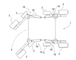
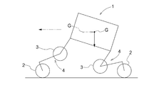
- FIG. 3 is a schematic plan view of the work vehicle in a turning state.
- FIG. 3 is a schematic plan view of the work vehicle in a straight traveling state. It is a schematic side view of a work vehicle in a straight traveling state. It is a side view of a support frame. It is a top view of a support frame. It is a front view of a support frame. It is a control block diagram by 2nd Embodiment.
- FIG. 26 is a view showing the third embodiment (hereinafter the same up to FIG. 25), and is an overall side view of a work vehicle.
- FIG. 2 is an overall plan view of the work vehicle. It is a top view of a refraction link mechanism. It is a side view of a bending link mechanism.
- FIG. 5 is a plan view showing a right turning state by the turning mechanism. It is a side view which shows the flat terrain running state of a working vehicle.
- FIG. 4 is a side view showing a state in which the work vehicle gets over the step.
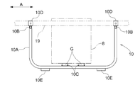
- the longitudinal direction of the vehicle body when defining the longitudinal direction of the vehicle body, it is defined along the vehicle body traveling direction, and when defining the horizontal direction of the vehicle body, the left and right are defined in a state viewed from the aircraft traveling direction. I do. That is, the direction indicated by the reference numeral (A) in FIG. 1 is the vehicle front-rear direction, and the direction indicated by the reference numeral (B) in FIG. 2 is the vehicle left-right direction.
- the work vehicle includes a vehicle body 1 that supports the entire vehicle and has a substantially rectangular shape in plan view, a plurality of (specifically, four) traveling wheels 2, and a plurality of traveling wheels. 2, a plurality of auxiliary wheels 3 provided corresponding to each of the two, a plurality of traveling wheels 2, and a refraction link mechanism 4 (an example of a vehicle body supporting portion) for supporting the plurality of traveling wheels 2 on the vehicle main body 1 so as to be freely repositionable.
- a hydraulically driven attitude change operation means 5 capable of changing the mechanism 4 and a plurality of hydraulic motors 6 for individually driving the plurality of traveling wheels 2 are provided.
- the bending link mechanism 4, the traveling wheel 2, and the auxiliary wheel 3 are provided on each of the front and rear sides of the vehicle body 1, one pair each on the right and left sides.
- the vehicle body 1 is provided with a rectangular frame-shaped body frame 7 that supports the whole, a hydraulic supply source 8 that sends out hydraulic oil toward the attitude change operation means 5, and a hydraulic supply source 8 that supplies the hydraulic oil to the attitude change operation means 5. And a valve mechanism 9 for controlling the operating oil.
- the hydraulic supply source 8 includes an engine and a hydraulic pump driven by the engine, and these are integrally connected.
- the hydraulic supply source 8 is mounted and supported by a support frame (support base) 10 connected to the lower side of the vehicle body frame 7, and is provided in a state of being located at the lower abdomen of the vehicle body 1.
- the hydraulic supply source 8 sends out and supplies hydraulic oil to the posture changing operation means 5 via a valve mechanism 9 by a hydraulic pump driven by an engine.
- the hydraulic supply 8 and the support frame 10 are connected and integrally slid laterally from the vehicle body 1 in a connected state.
- the support frame 10 can be detached, and can be mounted by sliding the support frame 10 to the vehicle body frame 7 sideways.
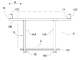
- the support frame 10 includes a pair of left and right bottom receiving members 10A formed by bending a round pipe material into a substantially U shape in side view, and front and rear sides of the bottom receiving member 10A.
- the end portions are connected to each other, and a pair of front and rear lateral support members 10B made of a round pipe material provided so as to extend to both left and right sides are integrally connected to form a frame.
- a pair of front and rear engine supports 10C are placed and connected by bolts over the left and right bottom receiving members 10A.
- connection bracket 10D made of a horizontally open channel material is connected to upper portions of both left and right end portions of the pair of front and rear sideways support members 10B.
- the left and right connection brackets 10D are open in the same direction, and are mounted laterally from one direction on a rectangular tubular front-rear frame 19 provided on both left and right lateral portions of the body frame 7 of the vehicle body 1. It is configured to be connected by bolts.
- a ground support 10E is provided below the pair of bottom receiving members 10A to support the ground receiving member 10A in a non-slip state while being grounded. Therefore, the support frame 10 is configured to be able to hold the posture of the entire vehicle body with the lower end portion in contact with the ground.
- the hydraulic supply source 8 is configured by integrally connecting the engine and a hydraulic pump.
- the hydraulic supply source 8 is mounted and supported by the front and rear engine supports 10C via the vibration-proof rubber G.
- the hydraulic pressure source 8 is provided so as to be housed under the vehicle body frame 7.
- the hydraulic supply source 8 can be slid laterally from the vehicle body 1 and removed.
- the support frame 10 can be slid laterally and attached.
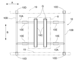
- the valve mechanism 9 is provided in a state of being mounted and supported on the upper side of the body frame 7 and includes a plurality of hydraulic control valves 11 for supplying and discharging hydraulic oil to the attitude changing operation means 5 or adjusting the flow rate.
- the upper part of the valve mechanism 9 is covered by a storage case 12.
- a control device 13 (an example of a control unit) that controls the operation of the valve mechanism 9 is provided above the storage case 12.
- an exterior frame 14 for protecting the valve mechanism 9 stored in the storage case 12, the control device 13 provided above, and the like is provided on the upper side of the body frame 7, for example, when the vehicle body 1 falls down.
- the exterior frame 14 is provided on both front and rear sides, and has a shape in which a rod-like body is bent substantially in a U shape in plan view and is bent in a substantially L shape in side view. Left and right ends are attached and fixed to the ends.
- the front and rear exterior frames 14 are provided such that their upper sides are close to each other, and have a shape that covers the outer peripheral sides of the valve mechanism 9, the control device 13, and the like.
- the front and rear exterior frames 14 are mounted so that the upper side faces outward in the front-rear direction, and a wide mounting plate is mounted above the front and rear exterior frames 14 to be used as a truck for carrying cargo. can do.
- the exterior frame 14 by attaching the exterior frame 14 so that the upper side faces one side in the front-rear direction, the exterior frame 14 can be used as a handle for a worker to grasp by hand.
- a support structure for supporting the traveling wheels 2 on the vehicle body 1 will be described.
- a plurality of (specifically, four) traveling wheels 2 are individually supported on the vehicle body 1 via the refraction link mechanism 4 so as to be vertically movable.
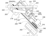
- the bending link mechanism 4 is supported by the vehicle body frame 7 so as to be rotatable around a vertical axis Y through a turning mechanism 16 (an example of turning operation means).
- the turning mechanism 16 is connected to the vehicle body frame 7 and supports the refracting link mechanism 4 in a freely rotatable manner. And a turning hydraulic cylinder (hereinafter, referred to as a turning cylinder) 18 for turning.
- a turning hydraulic cylinder hereinafter, referred to as a turning cylinder
- the vehicle-body-side support portion 17 is provided with a pair of rectangular frame-shaped front-facing frame members 19 provided at the lateral portions of the vehicle body frame 7.
- a connecting member 20 which is fitted and engaged in a state of being sandwiched from one side and is removably bolt-connected, an outer side pivotal support bracket 21 located at an outer side of the connecting member 20 in the vehicle longitudinal direction, and a connecting member 20.
- An inner pivot bracket 22 positioned at an inner location in the vehicle longitudinal direction, and a vertical pivot support shaft 23 supported by the outer pivot bracket 21.
- the refraction link mechanism 4 is rotatably supported around the axis Y.
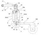
- the refraction link mechanism 4 has a base end 24 supported by the vehicle body-side support portion 17 in a state where the position in the vertical direction is fixed and rotatable around the longitudinal axis Y, and one end of the base end 24.
- a first link 25 rotatably supported around a horizontal axis X1 at a lower portion of the first link 25, and one end supported at the other end of the first link 25 rotatably around a horizontal axis X2 and the other end
- the base end portion 24 is provided in a rectangular frame shape in a plan view, and is rotatable around the vertical axis Y via the rotation support shaft 23 at a position biased inward in the vehicle width direction. In addition, it is supported by the outer-side pivot support bracket 21 of the vehicle-body-side support portion 17.
- the pivot cylinder 18 has one end rotatably connected to the inner pivot bracket 22 and the other end at a position where the base end 24 is displaced laterally with respect to the pivot 23. It is rotatably connected.
- a support shaft 27 provided at one end of the first link 25 is rotatably supported and supported on both left and right sides of the base end 24.
- the first link 25 is supported by a lower portion of the base end 24. 27 are rotatably connected around the axis.
- the first link 25 has a proximal end arm 25b and another end arm 25a. At one end of the first link 25, a base arm 25b extending diagonally upward and outward is integrally formed. The other end of the first link 25 is integrally formed with the other end arm 25a extending diagonally upward and outward.
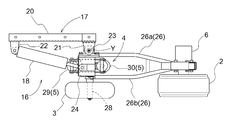
- the second link 26 includes a pair of left and right band-shaped plate bodies 26a and 26b, and is formed in a forked shape in plan view.
- a connecting portion of the second link 26 to the first link 25 is provided by a pair of plate bodies 26a and 26b.
- a connection support shaft 28 for connecting to the first link 25 is rotatably supported in a region sandwiched between the pair of plate bodies 26a and 26b.
- the traveling wheel 2 is supported at the swing-side end of the second link 26 opposite to the connection point to the first link 25.
- the swing-side end of the second link 26 is formed with an L-shaped extension 26A that extends substantially in an L-shape in a direction away from the vehicle body 1.
- the traveling wheel 2 is supported on the extension side end.
- the traveling wheel 2 is supported in a state where it is located on the outer side of the vehicle body in the left-right direction with respect to the refraction link mechanism 4. More specifically, the second link 26 is supported at the swinging end of the second link 26 so as to be located outside the vehicle body in the left-right direction.
- the hydraulic motor 6 is supported at the swing-side end of the second link 26 in a state of being located on the vehicle body inner side in the left-right direction (opposite to the traveling wheels 2).
- a posture changing operation means 5 is provided corresponding to each of the plurality of refraction link mechanisms 4 and capable of individually changing the posture of the refraction link mechanism 4.
- the posture changing operation means 5 includes a first hydraulic cylinder 29 capable of changing the swing posture of the first link 25 with respect to the vehicle body 1, and a second link 26 with respect to the first link 25.
- a second hydraulic cylinder 30 capable of changing the swinging posture is provided. The first hydraulic cylinder 29 and the second hydraulic cylinder 30 are collectively arranged near the first link 25, respectively.
- the first link 25, the first hydraulic cylinder 29, and the second hydraulic cylinder 30 are disposed in a state where the first link 25, the first hydraulic cylinder 29, and the second hydraulic cylinder 30 are located between the pair of plate bodies 26a, 26b of the second link 26 in plan view.
- the first hydraulic cylinder 29 is provided on the inner side in the vehicle longitudinal direction with respect to the first link 25 and is provided along the longitudinal direction of the first link 25.
- One end of the first hydraulic cylinder 29 is interlockingly connected to a lower portion of the base end 24 via an arcuate first interlocking member 31.
- One end of the first hydraulic cylinder 29 is interlockingly connected to a base end portion of the first link 25 via another second interlocking member 32.
- Both ends of the first interlocking member 31 and the second interlocking member 32 are pivotally connected so as to be relatively rotatable.
- the other end of the first hydraulic cylinder 29 is operatively connected to the other end side arm 25 a formed integrally with the first link 25.
- the second hydraulic cylinder 30 is provided on the opposite side of the first hydraulic cylinder 29, that is, on the outer side in the vehicle longitudinal direction with respect to the first link 25, and substantially along the longitudinal direction of the first link 25. Have been.
- One end of the second hydraulic cylinder 30 is operatively connected to a base arm 25 b formed integrally with the base of the first link 25.
- the other end of the second hydraulic cylinder 30 is interlockingly connected via a third interlocking member 34 to an arm 35 integrally formed at the base end of the second link 26.
- the other end of the second hydraulic cylinder 30 is also interlockingly connected to a swing end side portion of the first link 25 via another fourth interlocking member 36.
- the third interlocking member 34 and the fourth interlocking member 36 are pivotally connected at both side ends so as to be relatively rotatable.
- each of the first link 25, the second link 26, and the traveling wheel 2 is integrated while maintaining the relative posture constant. Specifically, it swings around the horizontal axis X1 at the pivotal connection point with respect to the base end portion 24.
- the second hydraulic cylinder 30 is extended and retracted in a state where the operation of the first hydraulic cylinder 29 is stopped, the second link 26 and the traveling wheel 2 are integrally formed while the posture of the first link 25 is kept constant. It swings around the horizontal axis X2 at the connecting point between the first link 25 and the second link 26.
- the auxiliary wheels 3 are supported by the intermediate bending portions of each of the plurality of bending link mechanisms 4 so as to be freely rotatable.
- the auxiliary wheel 3 is configured by a wheel having substantially the same outer diameter as the traveling wheel 2.
- a connection support shaft 28 that pivotally connects the first link 25 and the second link 26 is formed to extend so as to protrude outward from the second link 26 in the vehicle width direction.
- the auxiliary wheel 3 is rotatably supported at an extended projecting portion of the connection support shaft 28.
- each of the refraction link mechanism 4, the traveling wheel 2, the auxiliary wheel 3, and the posture changing operation means 5 integrally rotates around the axis Y of the rotation support shaft 23. It is freely supported by the outer pivot bracket 21. Then, by expanding and contracting the swivel cylinders 18, they are integrally rotated. From the straight running state in which the traveling wheel 2 faces in the front-rear direction, the turning operation can be performed by about 45 degrees in each of the left turning direction and the right turning direction.
- each of the turning mechanism 16, the bending link mechanism 4, the traveling wheel 2, the auxiliary wheel 3, and the attitude changing operation means 5 is provided. , Can be removed from the vehicle body 1 in a state of being integrally assembled.
- the above-described devices can be attached to the vehicle body 1 in a state of being integrally assembled.
- Hydraulic oil is supplied from the hydraulic supply source 8 to the first hydraulic cylinder 29 and the second hydraulic cylinder 30 of each of the plurality of bending link mechanisms 4 via the valve mechanism 9.
- hydraulic oil is supplied and discharged by the hydraulic control valve 11, and the first hydraulic cylinder 29 and the second hydraulic cylinder 30 can be operated to expand and contract.
- the hydraulic control valve 11 is controlled by the control device 13.
- each of the four second hydraulic cylinders 30 includes a head-side pressure sensor S1 and a cap-side pressure sensor S2.
- the head-side pressure sensor S1 detects the oil pressure in the head-side chamber of the second hydraulic cylinder 30.
- the cap-side pressure sensor S2 detects the oil pressure in the cap-side chamber of the second hydraulic cylinder 30.
- the detection results of the pressure sensors S1 and S2 are input to the control device 13.
- each of the four first hydraulic cylinders 29 and the four second hydraulic cylinders 30 is provided with a stroke sensor S3 capable of detecting the amount of expansion / contraction operation.
- the amount of expansion / contraction operation of each of the hydraulic cylinders 29 and 30 is a detection value corresponding to the swing position of the first link 25 and the second link 26 to be operated, and the stroke sensor S3 corresponds to a position detection sensor.
- the detection result of each stroke sensor S3 is input to the control device 13.
- the mounting positions of the pressure sensors S1 and S2 are not limited to the positions described above. Each of the pressure sensors S1 and S2 only needs to be able to detect (estimate) the oil pressure of the corresponding cap-side chamber or head-side chamber, and may be provided in a pipe from the valve mechanism 9 to the corresponding cap-side chamber or head-side chamber.
- the thrust required to support the vehicle body 1 is calculated based on the detection results of these sensors S1 and S2, and the supply of hydraulic oil to each of the second hydraulic cylinders 30 is controlled based on the calculation result. You.
- the vehicle body 1 is provided with an acceleration sensor S5 including, for example, a triaxial acceleration sensor.
- the front, rear, left and right inclinations of the vehicle body 1 are detected based on the detection result of the acceleration sensor S5, and the attitude of the vehicle body 1 is controlled based on the result. That is, the supply of the hydraulic oil to each of the first hydraulic cylinder 29 and the second hydraulic cylinder 30 is controlled so that the posture of the vehicle body 1 becomes the target posture.
- the traveling wheel 2 is provided with a rotation sensor S6 for detecting the rotation speed of the traveling wheel 2 driven by the hydraulic motor 6.
- Supply of hydraulic oil to the hydraulic motor 6 is controlled based on the rotation speed of the traveling wheel 2 detected by the rotation sensor S6 such that the rotation speed of the traveling wheel 2 becomes a target value.
- the configuration is such that the attitude of the refraction link mechanism 4 is changed by the hydraulic cylinders 29 and 30 as the hydraulically driven attitude change operation means 5, and the traveling drive is also performed by the hydraulic motor 6. Therefore, it is less affected by moisture, fine dust, etc., and is suitable for agricultural work.
- this working vehicle is in a normal traveling mode in a four-wheel traveling state in which all four traveling wheels 2 are in contact with the ground and all four auxiliary wheels 3 are lifted off the ground.
- various traveling modes can be adopted by changing the posture of the bending link mechanism 4 in addition to this mode.
- FIG. 7 shows a control block diagram.
- the control device 13 includes, for example, a microcomputer or the like, and can execute various controls according to a control program. Although not described in detail, the control device 13 controls the posture of the vehicle body 1 based on control information input by manual operation or control information stored in advance according to the work situation at that time. The control is performed so as to bring the state into an appropriate state. Although not shown, the control device 13 also controls the hydraulic oil for the plurality of hydraulic motors 6.
- the control device 13 detects the four first hydraulic cylinders 29 and the four second hydraulic cylinders 30 by the stroke sensors S3 provided in the respective hydraulic cylinders 29, 30.
- the hydraulic control valve 11 is switched so as to operate the hydraulic cylinders 29 and 30 so that the expansion / contraction operation amount detected by the operation becomes the detection value corresponding to the target posture.
- the expansion / contraction operation amount detected by the stroke sensor S3 provided in each hydraulic cylinder 29 is the target.
- Position control is performed to switch the hydraulic control valve 11 to operate each hydraulic cylinder 29 so that the detected value corresponds to the posture.
- the operation of the four second hydraulic cylinders 30 is controlled based on the detection information of the pressure sensors S1 and S2. Specifically, the thrust of the second hydraulic cylinder 30 is calculated based on the detection value of the head-side pressure sensor S1 and the detection value of the cap-side pressure sensor S2. Then, the operation of the second hydraulic cylinder 30 is controlled by switching the hydraulic control valve 11 so that the detected thrust becomes a target value that is set and stored in advance.
- the ground reaction force of the traveling wheels 2 is maintained at an appropriate value.
- the traveling wheels 2 move up and down while following the unevenness of the ground, and each of the traveling wheels 2 maintains an appropriate grounding state without slipping or hindering rotation. It is possible to drive satisfactorily on uneven terrain while supporting the vehicle.
- the control device 13 sets the expansion / contraction operation amount detected by the stroke sensor S3 provided in the turning cylinder 18 to a detection value corresponding to the target turning angle.
- the swing control for operating the swing cylinder 18 by switching the hydraulic control valve 11 is executed.
- the control device 13 controls the left and right traveling wheels 2 located on the front side or the left and right traveling wheels 2 located on the rear side when performing turning control while the work vehicle is moving and traveling.
- the operation of the posture changing operation means 5 is performed so that the center of gravity of the vehicle body 1 moves toward the side opposite to the direction in which the direction changing operation is performed in the vehicle longitudinal direction. Control.
- the control device 13 causes the refraction link mechanism 4 located on the side of the vehicle body front-rear direction on which the direction changing operation is performed to separate the vehicle body 1 from the traveling wheels 2 that are in contact with the ground.
- the posture changing operation means 5 is operated so as to approach the position.
- the turning cylinder 18 when the turning cylinder 18 is operated so that the left and right running wheels 2 on the front side in the vehicle body traveling direction turn leftward as shown in FIG.
- the left and right front hydraulic cylinders of the left and right bending cylinders 4 support the traveling wheels 2 on the front side of the vehicle body so that the base end of the second link 26 swings upward.
- the second hydraulic cylinder 30 is operated. As a result, the vehicle body 1 is switched to the front-back inclined position in which the front side is raised and the rear side is lowered.
- the center of gravity of the vehicle body 1 is directed to the side opposite to the side in which the direction change operation is performed in the vehicle body front-rear direction, as compared with the case where the vehicle is traveling straight. Will move.
- the load of the vehicle body 1 on the front traveling wheel 2 that is turned is received, in other words, the traveling wheel 2 serving as a movement resistance when changing the direction is received from the ground.
- the load can be reduced, and the direction can be changed smoothly.
- the stroke sensor S3 is used as the position detection sensor.
- a rotary potentiometer or the like provided at the swing support point of the first link 25 is used. Is also good.
- the configuration is such that the auxiliary wheel 3 is supported so as to be freely rotatable.
- the configuration may be such that the auxiliary wheel 3 is rotationally driven, or a configuration without such an auxiliary wheel 3 may be provided.
- the traveling wheel 2 is driven by the hydraulic motor 6.
- the power of the engine is supplied to the traveling wheel 2 via a mechanical transmission mechanism such as a chain transmission mechanism. 2 may be provided.
- various configurations may be used, such as a configuration driven by an electric motor, or a configuration in which the power of the engine is separately transmitted to the traveling wheels 2 via a speed change mechanism capable of continuously changing the speed. .
- the support frame 10 is detachably mounted on the vehicle body 1 by detaching or attaching the support frame 10 to the vehicle body frame 7 so that the hydraulic supply 8 is slid laterally.
- a configuration may be adopted in which the hydraulic supply source 8 is slid laterally with respect to the support frame 10 so that the hydraulic supply source 8 can be mounted and detachably supported.
- the support frame 10 is provided with the grounding support 10E that is grounded in a non-slip state.
- the grounding support 10E that is grounded in a non-slip state.
- a plurality of A configuration in which a caster wheel is provided and the grounding support is provided by the caster wheel may be employed.
- the hydraulic supply source 8 includes the engine and the hydraulic pump driven by the engine.
- the hydraulic pump may be driven by an electric motor instead of the engine.
- the attitude changing operation means 5 is configured to include the plurality of hydraulic cylinders 29 and 30, but instead of this configuration, the attitude is changed by providing a hydraulic motor at a pivot point between the links. It may be.
- the bending link mechanism 4 located on the side of the front-rear direction where the direction changing operation is performed separates the vehicle body 1 from the grounded traveling wheel 2 and is located on the opposite side.
- the configuration is such that the attitude changing operation means 5 is operated so that the bending link mechanism 4 moves the vehicle body 1 closer to the traveling wheel 2 that is in contact with the ground, but instead of this configuration, the direction changing operation is performed.
- the center of gravity may be moved by sliding a heavy object provided in the vehicle body 1, for example, an engine or the like, in the vehicle front-rear direction from the vehicle body 1 toward the opposite side.
- the stroke sensor S3 for detecting the amount of expansion / contraction operation of the turning cylinder 18 is provided.
- the rotary sensor provided at the pivot of the first link 25 is used. It is good also as a structure which detects the expansion / contraction operation amount with a potentiometer.
- the turning mechanism 16 (the turning operation means) is provided with the turning cylinder 18, but the turning operation may be performed by an electric motor or a hydraulic motor.
- the auxiliary wheel 3 is configured to be freely rotatable.
- the auxiliary wheel 3 may be configured to be driven to rotate, or may be configured without such an auxiliary wheel 3.
- the traveling wheels 2 are driven by the hydraulic motor 6.
- the power of the engine is supplied to the traveling wheels via a mechanical transmission mechanism such as a chain transmission mechanism. 2 may be provided.
- each of the four first hydraulic cylinders 29 and the four second hydraulic cylinders 30 is provided with a stroke sensor S3 capable of detecting a telescopic operation amount.
- the amount of expansion / contraction operation of each of the hydraulic cylinders 29 and 30 is a detection value corresponding to the swing position of the first link 25 and the second link 26 to be operated, and the detection result of each stroke sensor S3 is input to the control device 13. Is done.
- the vehicle body 1 is provided with an acceleration sensor S5 including, for example, a three-axis acceleration sensor.
- the front, rear, left and right inclinations of the vehicle body 1 are detected based on the detection result of the acceleration sensor S5, and the attitude of the vehicle body 1 is controlled based on the result. That is, the supply of the hydraulic oil to each of the first hydraulic cylinder 29 and the second hydraulic cylinder 30 is controlled so that the posture of the vehicle body 1 becomes the target posture.
- the traveling wheel 2 is provided with a rotation sensor S6 (an example of a driving speed detecting means) for detecting the rotation speed of the traveling wheel 2 driven by the hydraulic motor 6.
- Supply of hydraulic oil to the hydraulic motor 6 is controlled based on the rotation speed of the traveling wheel 2 detected by the rotation sensor S6 such that the rotation speed of the traveling wheel 2 becomes a target value.
- the configuration is such that the attitude of the refraction link mechanism 4 is changed by the hydraulic cylinders 29 and 30 as the hydraulically driven attitude change operation means 5, and the traveling drive is also performed by the hydraulic motor 6. Therefore, it is less affected by moisture, fine dust, etc., and is suitable for agricultural work.
- this working vehicle is in a normal traveling mode in a four-wheel traveling state in which all four traveling wheels 2 are in contact with the ground and all four auxiliary wheels 3 are lifted off the ground.
- various traveling modes can be adopted by changing the posture of the bending link mechanism 4 in addition to this mode.
- FIG. 17 shows a control block diagram.
- the control device 13 includes, for example, a microcomputer or the like, and can execute various controls according to a control program. Then, the control device 13 sets the posture of the vehicle body 1 in an appropriate state according to the work situation at that time based on control information input by manual operation or control information set and stored in advance. And a posture control unit 100 (an example of a control unit) that executes the control so as to perform the control.
- a posture control unit 100 an example of a control unit
- the posture control unit 100 controls each of the four hydraulic cylinders 29 and the four second hydraulic cylinders 30 for each of the hydraulic cylinders 29 in both the state where the traveling vehicle is stopped traveling and the state where the traveling vehicle is traveling. , 30 so that the operation amount of the hydraulic cylinders 29, 30 is switched by switching the hydraulic control valve 11 so that the expansion / contraction operation amount detected by the stroke sensor S3 provided in the stroke sensor S3 becomes a detection value corresponding to the target posture. Execute control.
- the control device 13 adjusts the traveling speed of the vehicle body 1 to an appropriate speed based on control information input by a manual operation or control information set and stored in advance according to the work situation at that time.
- a traveling drive control unit 101 for controlling the plurality of hydraulic motors 6 is provided.
- the traveling drive control unit 101 controls the operation of the hydraulic motor 6 such that the rotation speed of the traveling wheel 2 detected by the rotation sensor S6 becomes a target speed set in advance based on the above-described control information. I do.
- This work vehicle is provided with an idling state detecting means Q for detecting whether or not the traveling wheel 2 is idling, for example, when traveling on uneven terrain having many irregularities.
- the idling state detecting means Q detects a pressure sensor S4 for detecting an internal pressure of the hydraulic oil supply passage in the hydraulic motor 6 and, based on information detected by the pressure sensor S4, when the internal pressure falls below a preset value.
- a determination unit (determination unit 102) that determines that the traveling wheel 2 is in the idling state is configured.
- a pressure sensor S4 for detecting the internal pressure of the hydraulic oil supply passage corresponding to each of the four hydraulic motors 6 is provided. Has been entered. Then, the control device 13 compares the input detection value (internal pressure) of the pressure sensor S4 with a preset setting value, and determines whether the detection value (internal pressure) of any of the pressure sensors S4 is the setting value. When the vehicle speed is lower than the predetermined value, a determination unit 102 (an example of a determination unit) that determines that the corresponding traveling wheel 2 is idling is provided.
- the attitude control unit 100 operates the second hydraulic cylinder 30 so as to lower the corresponding traveling wheel 2, and detects the pressure sensor S4. When the value (internal pressure) returns to or above the set value, the operation of the second hydraulic cylinder 30 is stopped.
- the traveling wheel 2 idles when there is a concave portion on the ground and the traveling wheel 2 is lifted off the ground, or when traveling on a slippery road surface.
- the load pressure on the hydraulic motor 6 is greatly reduced.
- Such a change in the load pressure is detected by the pressure sensor S4, and when the detected value of the pressure sensor S4 falls below the set value, the operation of the second hydraulic cylinder 30 is controlled, so that the traveling wheel 2 is properly driven.
- This is a state in which force is exerted, and the idling state can be eliminated.
- the traveling wheels 2 move up and down while following the unevenness of the ground, and each of the traveling wheels 2 maintains an appropriate grounding state without slipping or hindering rotation. It is possible to drive satisfactorily on uneven terrain while supporting the vehicle.
- the idling state detecting means Q is configured by the pressure sensor S4 and the determination unit 102.
- the following configuration may be employed.
- a rotation sensor S6 (an example of a driving speed detecting unit) for detecting the driving speed of the hydraulic motor 6, a traveling speed detecting unit for detecting the actual traveling speed of the vehicle body 1, and a hydraulic motor detected by the rotation sensor S6.
- the discriminating means for discriminating that the traveling wheel 2 is in the idling state constitutes the idling state detecting means Q. It may be done.
- the traveling speed detecting means for example, an average value of the driving speeds of the four hydraulic motors 6 provided corresponding to the four traveling wheels 2 is obtained, and the traveling speed is obtained from the average value. You may do so.
- a measuring device that can determine the absolute traveling speed of the work vehicle with respect to the ground using a vehicle speed sensor using a millimeter wave radar may be used.
- control device 13 compares the drive speed of one hydraulic motor 6 to be measured with the actual travel speed of the vehicle body 1 measured by the travel speed detection means as described above, and determines that the drive speed is When the traveling speed becomes higher than the actual traveling speed by a set amount or more, a process of determining that the traveling wheel 2 is in the idling state is executed to determine the idling state.
- the ascent / descent support mechanism has been described as being constituted by the bending link mechanism 4 in which two links 25 and 26 are pivotally connected.
- the invention is not limited to the link mechanism, but may be a configuration in which the traveling wheels 2 are supported via a support mechanism having a cylinder structure that can expand and contract with respect to the vehicle body 1 in the vertical direction.
- the posture changing operation means 5 is configured to include the plurality of hydraulic cylinders 29, 30.
- the posture changing operation means 5 includes a hydraulic motor or an electric motor at a pivot point between the links. May be changed.
- the traveling drive device is configured by the hydraulic motor 6, but instead of this configuration, the travel drive device is driven by an electric motor, or the power of the engine can be continuously changed.
- Various configurations may be used, such as a configuration in which each is transmitted to the traveling wheels 2 via a simple transmission mechanism.
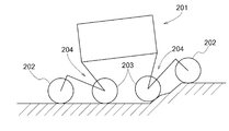
- the work vehicle includes a vehicle body 201 that supports the entire vehicle and is substantially rectangular in plan view, a plurality of (specifically, four) traveling wheels 202, and a plurality of traveling wheels 202.
- a plurality of auxiliary wheels 203 provided corresponding to each of the wheels 202;
- a refraction link mechanism 204 (an example of a lifting support mechanism) for supporting the plurality of traveling wheels 202 on the vehicle main body 201 so as to be individually changeable in position;
- a hydraulically driven attitude change operation means 205 capable of changing the link mechanism 204 and a hydraulic motor 206 (an example of a plurality of travel driving devices) for individually driving the plurality of traveling wheels 202 are provided.
- Each of the refraction link mechanism 204, the traveling wheel 202, and the auxiliary wheel 203 is provided on each of the front and rear sides of the vehicle main body 201, respectively, as a pair of left and right.
- the vehicle body 201 is provided with a rectangular frame-shaped body frame 207 that supports the whole, a hydraulic supply source 208 that sends out hydraulic oil toward the posture changing operation unit 205, and a hydraulic supply source 208 that supplies the hydraulic oil to the posture changing operation unit 205. And a valve mechanism 209 for controlling the operating oil.
- the hydraulic supply source 208 includes an engine and a hydraulic pump driven by the engine, and these are integrally connected.
- the hydraulic supply source 208 is mounted and supported by a support 210 connected to the lower side of the vehicle body frame 207, and is provided in a state of being located at the lower abdomen of the vehicle main body 201.
- the hydraulic supply source 208 sends out and supplies hydraulic oil to the posture changing operation means 205 via a valve mechanism 209 by a hydraulic pump driven by an engine. Then, although not shown, by removing the support base 210 from the body frame 207, the hydraulic supply source 208 and the support base 210 are connected and integrally slid from the vehicle body 201 to the lateral side. It is possible to remove it, and it is possible to slide it to the side and attach it again by attaching the support 210 to the vehicle body frame 207 again.
- the valve mechanism 209 is provided in a state of being mounted and supported on the upper side of the vehicle body frame 207, and includes a plurality of hydraulic control valves 211 for supplying and discharging hydraulic oil to the attitude changing operation means 205 or adjusting the flow rate.
- the upper part of the valve mechanism 209 is covered by the storage case 212.
- a control device 213 for controlling the operation of the valve mechanism 209 is provided above the storage case 212.
- an outer frame 214 for protecting the valve mechanism 209 stored in the storage case 212 and the control device 213 provided above is provided on the upper side of the vehicle body frame 207.
- the exterior frame 214 is provided on both front and rear sides, and has a shape in which a rod-shaped body is bent substantially U-shaped in plan view and is bent substantially L-shaped in side view. Left and right ends are attached and fixed to the ends.
- the front and rear exterior frames 214 are provided such that their upper sides are close to each other, and have a shape that covers the outer peripheral sides of the valve mechanism 209, the control device 213, and the like.
- a support structure for supporting the traveling wheels 202 on the vehicle body 201 will be described.
- a plurality of (specifically, four) traveling wheels 202 are individually supported on the vehicle body 201 via a refraction link mechanism 204 so as to be able to move up and down.
- the bending link mechanism 204 is supported by the vehicle body frame 207 via a turning mechanism 216 so as to be rotatable around a vertical axis Y.
- the turning mechanism 216 is connected to the vehicle body frame 207 and supports the bending link mechanism 204 so as to be rotatable.
- the turning mechanism 216 also includes a turning section 217 for turning the bending link mechanism 204 (see FIGS. 20 and 21).
- Hydraulic cylinder (hereinafter referred to as a swing cylinder) 18 is provided.
- the vehicle-body-side support portion 217 is positioned horizontally with respect to a pair of upper and lower rectangular tubular front-rear frame members 219 provided at the lateral portions of the vehicle body frame 207.
- a connection member 220 that is fitted and engaged in a state of being pinched from the outside and is removably bolted, and an outer side pivotal support bracket 221 that is located on the outer side of the connection member 220 in the vehicle longitudinal direction;
- An inner pivot bracket 222 located at an inner side of the member 220 in the longitudinal direction of the vehicle body, and a vertical pivot shaft 223 supported by the outer pivot bracket 221.
- the refracting link mechanism 204 is rotatably supported around the axis Y of the H.223.
- the bending link mechanism 204 has a base end 224 supported by the vehicle body-side support portion 217 in a state where the position in the vertical direction is fixed and rotatable around the vertical axis Y, and one end of the base end 224.
- a first link 225 rotatably supported around a horizontal axis X1 at a lower portion of the first link 225, and one end portion rotatably supported around the horizontal axis X2 at the other end of the first link 225 and the other end thereof
- a second link 226 on which the traveling wheel 202 is supported.
- the base end portion 224 is provided in a rectangular frame shape in a plan view, and is rotatable around the vertical axis Y via the rotation support shaft 223 at a position deviated inward in the vehicle width direction. In addition, it is supported by the outer side support bracket 221 of the vehicle body side support portion 217.
- the pivot cylinder 218 has one end rotatably connected to the inner pivot bracket 222 and the other end at a position where the base end 224 is laterally displaced from the pivot shaft 223. It is rotatably connected.
- a support shaft 227 provided at one end of the first link 225 is rotatably supported and supported on both left and right sides of the base end 224.
- the first link 225 is supported by a lower portion of the base end 224 with respect to the support shaft. 227 are rotatably connected around the axis.
- the first link 225 has a base end arm 225b and a second end arm 225a. At one end of the first link 225, a base arm 225b extending diagonally upward and outward is integrally formed. The other end side of the first link 225 is integrally formed with the other end side arm portion 225a extending diagonally upward and outward.
- the second link 226 includes a pair of left and right band-shaped plate bodies 226a and 226b, and is formed in a forked shape in plan view.
- a pair of plate bodies 226a and 226b are spaced from each other at the connection point of the second link 226 to the first link 225.
- a connection support shaft 228 for connecting to the first link 225 is rotatably supported in a region sandwiched between the pair of plate members 226a and 226b.
- the traveling wheel 202 is supported at the swing-side end of the second link 226 opposite to the connection point to the first link 225. As shown in FIG.
- the swing-side end of the second link 226 is formed with an L-shaped extension 226 ⁇ / b> A extending substantially in an L-shape in a direction away from the vehicle body 201.
- a traveling wheel 202 is supported on the extension side end.
- the traveling wheel 202 is supported on the refraction link mechanism 204 so as to be located outside the vehicle body in the left-right direction.
- the second link 226 is supported at the swing-side end portion in a state of being located outside the vehicle body in the left-right direction.
- a posture changing operation means 205 is provided for each of the plurality of bending link mechanisms 204, which can change the posture of the bending link mechanism 204 individually.
- the posture changing operation means 205 includes a first hydraulic cylinder 229 capable of changing the swing posture of the first link 225 with respect to the vehicle body 201, and a second link 226 with respect to the first link 225. And a second hydraulic cylinder 230 capable of changing the swinging posture of the second hydraulic cylinder 230.
- the first hydraulic cylinder 229 and the second hydraulic cylinder 230 are respectively arranged collectively near the first link 225.
- the first link 225, the first hydraulic cylinder 229, and the second hydraulic cylinder 230 are provided in a state where they are located between the pair of plate bodies 226a and 226b of the second link 226 in plan view.
- the first hydraulic cylinder 229 is located on the inner side in the vehicle longitudinal direction with respect to the first link 225, and is provided along the longitudinal direction of the first link 225.
- One end of the first hydraulic cylinder 229 is operatively connected to a lower part of the base end 224 via an arc-shaped first interlocking member 231.
- One end of the first hydraulic cylinder 229 is operatively connected to a base end side of the first link 225 via another second interlocking member 232.
- Both ends of the first interlocking member 231 and the second interlocking member 232 are pivotally connected so as to be relatively rotatable.
- the other end of the first hydraulic cylinder 229 is operatively connected to the other end side arm 225 a formed integrally with the first link 225.
- the second hydraulic cylinder 230 is provided on the opposite side of the first hydraulic cylinder 229, that is, on the outer side in the vehicle longitudinal direction with respect to the first link 225, and substantially along the longitudinal direction of the first link 225. Have been. One end of the second hydraulic cylinder 230 is operatively connected to a base arm 225 b formed integrally with the base of the first link 225. The other end of the second hydraulic cylinder 230 is operatively connected to an arm 35 integrally formed at a base end portion of the second link 226 via a third interlocking member 234. The other end of the second hydraulic cylinder 230 is also operatively connected to a swing end side portion of the first link 225 via another fourth interlocking member 236. The third interlocking member 234 and the fourth interlocking member 236 are connected to each other at both ends so as to be relatively rotatable.
- each of the first link 225, the second link 226, and the traveling wheel 202 is integrated while keeping the relative posture constant. Specifically, it swings around the horizontal axis X ⁇ b> 1 at the pivotal connection point to the base end 224.
- the second hydraulic cylinder 230 is expanded and contracted in a state where the operation of the first hydraulic cylinder 229 is stopped, the second link 226 and the traveling wheel 202 are integrally formed while the posture of the first link 225 is maintained constant.
- the first link 225 and the second link 226 swing around the horizontal axis X2 at the connection point.
- Auxiliary wheels 203 are freely rotatably supported by the intermediate bending portions of each of the plurality of bending link mechanisms 204.
- the auxiliary wheel 203 is configured by a wheel having substantially the same outer diameter as the traveling wheel 202.
- a connection support shaft 228 that pivotally connects the first link 225 and the second link 226 is formed to extend outward from the second link 226 in the vehicle width direction.
- An auxiliary wheel 203 is rotatably supported at an extended projecting portion of the connection support shaft 228.
- the hydraulic motor 206 is provided so as to be located between the intermediate bending portion of the bending link mechanism 204, that is, the position where the auxiliary wheel 203 is located, and the support portion of the traveling wheel 202. Specifically, as shown in FIG. 21, the hydraulic motor 206 is provided in a state of being mounted and supported on the upper part of the L-shaped extending portion 226A of the second link 226.
- the hydraulic motor 206 is configured to drive the traveling wheel 202 and the auxiliary wheel 203 of the bending link mechanism 204 provided with the hydraulic motor 206, respectively.
- the power of the hydraulic motor 206 is transmitted to the traveling wheels 202 and the auxiliary wheels 203 via the chain transmission mechanism 240.
- two drive sprockets 242 and 243 are supported on a lateral output shaft 241 of the hydraulic motor 206 so as to be integrally rotatable.
- the first transmission chain 245 is wound around one of the driving sprockets 242 and the driven sprocket 244 supported so as to be integrally rotatable on the rotation support shaft 202A of the traveling wheel 202.
- the second transmission chain 247 is wound around the other drive sprocket 243 of the two drive sprockets 242 and 243 and the driven sprocket 246 supported integrally and rotatably on the rotation support shaft 203A of the auxiliary wheel 203. I have.
- the periphery of the chain transmission mechanism 240 is covered with a case 248 so that weeds, stem stalks and the like are not involved.
- the two drive sprockets 242, 243 have the same diameter and the same number of teeth.
- the two driven sprockets 244 and 246 have the same diameter and the same number of teeth.
- the traveling wheel 202 and the auxiliary wheel 203 have the same outer diameter. Accordingly, the traveling wheel 202 and the auxiliary wheel 203 are synchronously driven at the same rotational speed with the rotational drive of the hydraulic motor 206.
- each of the bending link mechanism 204, the traveling wheel 202, the auxiliary wheel 203, the hydraulic motor 206, the chain transmission mechanism 240, and the attitude changing operation means 205 are integrally rotated.
- the shaft 223 is supported by the outer pivot bracket 221 so as to be rotatable around the axis Y of the shaft 223. Then, by expanding and contracting the swivel cylinders 218, they are integrally rotated. From the straight running state in which the traveling wheel 202 faces in the front-rear direction, the turning operation can be performed by about 45 degrees in each of the left turning direction and the right turning direction.
- auxiliary wheels 203 it is also possible to ground all the auxiliary wheels 203 and run with all running wheels 202 levitated.
- a running mode for example, when the vehicle rides over a step, the vehicle can be brought close to the point of the step, and the traveling wheel 202 and the second link 226 that are lifted upward are put on the step as they are to get over the step.
- the distance between the wheels contacting the ground in the front-rear direction is reduced, so that the vehicle can make a small turn.
- each of the change operation means 205 can be detached from the vehicle main body 201 in a state where they are integrally assembled. Further, by connecting the connecting member 220 to the front-facing frame body 219 by bolts, the above-described devices can be attached to the vehicle main body 201 in a state of being integrally assembled.
- Hydraulic oil is supplied from the hydraulic supply source 208 to the first hydraulic cylinder 229 and the second hydraulic cylinder 230 of each of the plurality of bending link mechanisms 204 via the valve mechanism 209.
- hydraulic oil is supplied and discharged by the hydraulic control valve 211, so that the first hydraulic cylinder 229 and the second hydraulic cylinder 230 can be operated to expand and contract.
- the traveling wheel 202 is provided with a rotation sensor S6 (an example of a driving speed detecting unit) that detects the rotational speed of the traveling wheel 202 driven by the hydraulic motor 206.
- Supply of hydraulic oil to the hydraulic motor 206 is controlled based on the rotation speed of the traveling wheel 202 detected by the rotation sensor S6 such that the rotation speed of the traveling wheel 202 becomes a target value. That is, by adjusting the flow rate of the hydraulic oil by the hydraulic control valve 211 corresponding to the hydraulic motor 206, the rotation speed of the hydraulic motor 206, that is, the traveling wheels 202 and the auxiliary wheels 203 can be changed.
- Each of the four first hydraulic cylinders 229 and the four second hydraulic cylinders 230 is provided with a stroke sensor (not shown) capable of detecting the amount of expansion / contraction operation.
- the vehicle body 201 is provided with an acceleration sensor S5 including, for example, a triaxial acceleration sensor or the like.
- the front, rear, left and right inclinations of the vehicle body 201 are detected based on the detection result of the acceleration sensor S5, and the attitude of the vehicle body 201 is controlled based on the result. That is, supply of hydraulic oil to each of the first hydraulic cylinder 229 and the second hydraulic cylinder 230 is controlled based on the detection result of the stroke sensor so that the posture of the vehicle body 201 becomes the target posture.
- the hydraulic cylinders 229 and 230 and the hydraulic motors 206 are controlled by the control device 213 based on control information input by manual operation or control information set and stored in advance.
- the power of the hydraulic motor 206 as the traveling drive device is transmitted to the traveling wheels 202 and the auxiliary wheels 203 via the chain transmission mechanism 240, but instead of this configuration, the hydraulic motor The power of the motor 206 may be transmitted to the traveling wheels 202 and the auxiliary wheels 203 via a transmission belt, or the power may be transmitted via a gear transmission mechanism in which a plurality of gears are engaged and transmitted. .
- the traveling drive device (the hydraulic motor 206) is provided so as to be located between the intermediate refraction portion of the refraction link mechanism 204 and the support portion of the traveling wheel 202.
- the traveling drive device (the hydraulic motor 206) may be supported on the vehicle body 201 side.
- the traveling drive device is configured by the hydraulic motor 206 that drives the traveling wheel 202 and the auxiliary wheel 203 provided in the corresponding bending link mechanism 204, respectively.
- various configurations may be used, such as a configuration driven by an electric motor, or a configuration in which the power of the engine is separately transmitted to the traveling wheels 202 via a speed change mechanism capable of continuously changing the speed. Is also good.
- the posture changing operation means 205 is configured to include the plurality of hydraulic cylinders 229 and 230. May be changed.
- the refraction link mechanism 204 has a configuration in which the two links 225 and 226 are pivotally connected. Instead of this configuration, the refraction link mechanism 204 may include three or more links.
Landscapes
- Engineering & Computer Science (AREA)
- Mechanical Engineering (AREA)
- Mining & Mineral Resources (AREA)
- Civil Engineering (AREA)
- General Engineering & Computer Science (AREA)
- Structural Engineering (AREA)
- Chemical & Material Sciences (AREA)
- Combustion & Propulsion (AREA)
- Transportation (AREA)
- Vehicle Body Suspensions (AREA)
Abstract
This working vehicle is provided with: a first link 25 having one end which is pivotally supported by the vehicle body 1; a second link 26 having one end which is pivotally connected to the other end of the first link 25, and having the other end by which a traveling wheel 2 is supported; a first hydraulic cylinder 29 capable of changing the rocking position of the first link 25; and a second hydraulic cylinder 30 capable of changing the rocking position, relative to the first link 25, of the second link 26. The operation of the first hydraulic cylinder 29 is controlled on the basis of the result of detection by a position detection sensor so that the rocking position of the first link 25 reaches a target position, and the operation of the second cylinder 30 is controlled on the basis of the results of detection by pressure sensors S1, S2 so that thrust reaches a target value.
Description
本発明は、凹凸の多い路面(不整地)を走行するのに適した作業車に関する。作業車は、後述する4脚輪駆動ロボットを含むが、これに限定するものではない。
The present invention relates to a work vehicle suitable for traveling on a road surface (rough terrain) having many irregularities. The work vehicle includes, but is not limited to, a four-wheel drive robot described below.
[背景技術1]
従来では、4つの走行車輪を夫々、2つの関節を持ち屈伸操作可能に構成されたリンク機構を介して車両本体に支持し、リンク機構に電動モータと減速機構等が内装され、電動モータの駆動力によりリンク機構が屈伸駆動可能に構成されたものがあった(例えば、特許文献1参照)。 [Background Art 1]
Conventionally, four traveling wheels are respectively supported on a vehicle body via a link mechanism having two joints and configured to be able to bend and extend, and the link mechanism includes an electric motor and a deceleration mechanism, and drives the electric motor. There has been a configuration in which a link mechanism is configured to be able to bend and extend by a force (for example, see Patent Document 1).
[背景技術2]
従来では、4つの走行車輪を夫々、2つの関節を持ち屈伸操作可能に構成されたリンク機構を介して本体に支持し、リンク機構に電動モータと減速機構等が内装され、電動モータの駆動力によりリンク機構が屈伸駆動可能に構成されたものがあった(例えば、特許文献1参照)。 [Background Art 2]
Conventionally, four running wheels are respectively supported on a main body via a link mechanism having two joints and configured to be able to bend and extend, and the link mechanism is provided with an electric motor and a reduction mechanism, and the driving force of the electric motor is provided. In some cases, the link mechanism is configured to be able to bend and extend (see, for example, Patent Document 1).
[背景技術3]
従来では、4つの走行車輪を夫々、2つの関節を持ち屈伸操作可能に構成されたリンク機構を介して車両本体に支持し、電動モータの駆動力によりリンク機構が屈伸駆動可能に構成され、走行車輪は電動モータにより各別に回転駆動するようにしたものがあった(例えば、特許文献1参照)。 [Background Art 3]
Conventionally, four traveling wheels are supported on a vehicle body via a link mechanism which has two joints and is configured to be able to bend and extend, and the link mechanism is configured to be able to bend and extend by a driving force of an electric motor. Some wheels are individually driven to rotate by an electric motor (for example, see Patent Document 1).
[背景技術4]
従来では、4つの走行車輪を夫々、横軸周りで揺動可能な2つの関節を持ち屈伸操作可能に構成されたリンク機構を介して車両本体に支持し、電動モータの駆動力によりリンク機構が屈伸駆動可能に構成され、走行車輪は、左右方向の向きが固定される状態で支持されたものがあった(例えば、特許文献1参照)。 [Background Art 4]
Conventionally, four traveling wheels are each supported on a vehicle body via a link mechanism having two joints capable of swinging about a horizontal axis and capable of bending and extending, and the link mechanism is driven by an electric motor. There has been a vehicle that is configured to be able to bend and extend and that the traveling wheel is supported in a state where the direction in the left-right direction is fixed (for example, see Patent Document 1).
[背景技術5]
従来では、4つの走行車輪を夫々、2つの関節を持ち屈伸操作可能に構成されたリンク機構を介して車両本体に支持し、電動モータの駆動力によりリンク機構が屈伸駆動可能に構成され、走行車輪は電動モータにより各別に回転駆動するようにしたものがあった(例えば、特許文献1参照)。 [Background Art 5]
Conventionally, four traveling wheels are supported on a vehicle body via a link mechanism which has two joints and is configured to be able to bend and extend, and the link mechanism is configured to be able to bend and extend by a driving force of an electric motor. Some wheels are individually driven to rotate by an electric motor (for example, see Patent Document 1).
[課題1]
[背景技術1]に対応する課題は、以下の通りである。
上記従来構成における車輪支持構造は、走行路面に凹凸があってもリンク機構を屈伸させながら車両本体を適正な姿勢に維持して走行することを可能にしたものである。そこで、このような車輪支持構造を、走行路面に凹凸がある作業地で走行する農用の作業車に適用することが考えられる。しかし、上記従来構成における車輪支持構造は農用の作業車には採用し難いものとなっていた。 [Issue 1]
The problems corresponding to [Background Art 1] are as follows.
The wheel supporting structure in the above-described conventional configuration enables the vehicle to run while maintaining the vehicle body in an appropriate posture while bending and extending the link mechanism even when the traveling road surface has irregularities. Therefore, it is conceivable to apply such a wheel support structure to an agricultural work vehicle traveling on a work place having unevenness on a traveling road surface. However, the wheel support structure in the above-mentioned conventional configuration has been difficult to adopt for agricultural work vehicles.
説明を加えると、農用の作業車では、作業車の近傍において、走行に伴って発生する土埃や収穫作業に伴って作物から発生する浮遊塵等の細かな塵埃が多く発生することがあり、雨水や朝露等が原因で水分が付着することもある。上記従来構成では、走行車輪を支持するためのリンク機構が、内装された電動モータにより屈伸駆動されるものであるから、細かな塵埃や水分等がリンク機構の内部に侵入すると、電動モータや減速機構等に不具合が生じるおそれがある。
In addition, in the case of agricultural work vehicles, in the vicinity of the work vehicle, a large amount of fine dust such as dust generated during traveling and floating dust generated from crops during harvesting work may be generated. In some cases, moisture may adhere due to dew or morning dew. In the above-described conventional configuration, the link mechanism for supporting the traveling wheels is driven to bend and stretch by the built-in electric motor. Therefore, when fine dust or moisture enters the link mechanism, the electric motor and the deceleration are reduced. Failure may occur in the mechanism or the like.
ところで、上記したような不利を回避するために、電動モータに比べて耐水性や耐塵性に優れた油圧シリンダを用いて屈折リンク機構を操作する構成が考えられる。このように油圧シリンダを用いて屈折リンク機構を操作する場合、屈折リンク機構における各リンク毎に油圧シリンダが必要であり、油圧シリンダの個数が多くなる。その結果、各油圧シリンダを制御するための構成が複雑になるおそれがある。
By the way, in order to avoid the above-mentioned disadvantage, a configuration in which the refraction link mechanism is operated using a hydraulic cylinder having better water resistance and dust resistance than the electric motor may be considered. When the bending link mechanism is operated using the hydraulic cylinder in this way, a hydraulic cylinder is required for each link in the bending link mechanism, and the number of hydraulic cylinders increases. As a result, the configuration for controlling each hydraulic cylinder may be complicated.
そこで、制御構成をできるだけ簡素なものにしながら、細かな塵埃や水分等が侵入するおそれが大きい作業環境において、凹凸の多い作業地であっても車両本体が適正な姿勢を維持することが可能な作業車が要望されていた。
Therefore, the vehicle body can maintain an appropriate posture even in a work place with a lot of irregularities in a work environment in which fine dust and moisture are likely to enter while keeping the control configuration as simple as possible. A working vehicle was desired.
[課題2]
[背景技術2]に対応する課題は、以下の通りである。
上記従来構成における車輪支持構造は、走行路面に凹凸があってもリンク機構を屈伸させながら本体を適正な姿勢に維持して走行することを可能にしたものである。そこで、このような車輪支持構造を、例えば、圃場、果樹園、山間値等で走行する農用の作業車に適用することが考えられる。しかし、上記従来構成における車輪支持構造はこれらの作業車には採用し難いものとなっていた。 [Issue 2]
The issues corresponding to [Background Art 2] are as follows.
The wheel support structure in the above-described conventional configuration enables the vehicle to travel while maintaining the body in an appropriate posture while bending and extending the link mechanism even when the traveling road surface has irregularities. Thus, it is conceivable to apply such a wheel support structure to, for example, an agricultural work vehicle traveling in a field, an orchard, a mountain range, or the like. However, the wheel support structure in the above-described conventional configuration has been difficult to employ in these work vehicles.
農用の作業車では、作業車の近傍において、走行に伴って発生する土埃や収穫作業に伴って作物から発生する浮遊塵等の細かな塵埃が多く発生することがあり、雨水や朝露等が原因で水分が付着することもある。上記従来構成では、走行車輪を支持するためのリンク機構が、内装された電動モータにより屈伸駆動されるものであるから、細かな塵埃や水分等がリンク機構の内部に侵入すると、電動モータや減速機構等に不具合が生じるおそれがある。
In the case of agricultural work vehicles, in the vicinity of the work vehicle, fine dust such as dust generated during traveling and floating dust generated from crops during harvesting work may be generated in large quantities, which may be caused by rainwater or morning dew. In some cases, moisture may adhere. In the above-described conventional configuration, the link mechanism for supporting the traveling wheels is driven to bend and stretch by the built-in electric motor. Therefore, when fine dust or moisture enters the link mechanism, the electric motor and the deceleration are reduced. Failure may occur in the mechanism or the like.
そこで、細かな塵埃や水分等が侵入するおそれが大きい作業環境において、凹凸の多い作業地であっても、車両本体が適正な姿勢を維持することが可能でありながら、しかも、低重心で安定した状態で移動走行することが可能な作業車が望まれていた。
Therefore, in a work environment where there is a great risk of intrusion of fine dust, moisture, etc., the vehicle body can maintain an appropriate posture even in a work place with many irregularities, and has a low center of gravity and stability. There has been a demand for a work vehicle capable of moving and traveling in a state where the vehicle is running.
[課題3]
[背景技術3]に対応する課題は、以下の通りである。
上記従来構成における車輪支持構造は、走行路面に凹凸があってもリンク機構を屈伸させながら車両本体を適正な姿勢に維持して走行することを可能にしたものである。しかし、上記従来構成では、凹凸の多い不整地を走行する際に、例えば、いずれかの走行車輪が凹部に入り込み、空回りしたような場合であってもリンク機構はそのままを姿勢を維持するので、その他の走行車輪によって車体を支持して、当該走行車輪は空回り状態が長く続く等の不利な面があり、改善の余地がある。 [Issue 3]
The issues corresponding to [Background Art 3] are as follows.
The wheel supporting structure in the above-described conventional configuration enables the vehicle to run while maintaining the vehicle body in an appropriate posture while bending and extending the link mechanism even when the traveling road surface has irregularities. However, in the above-described conventional configuration, when traveling on uneven terrain with a lot of irregularities, for example, even if one of the traveling wheels enters the concave portion and idles, the link mechanism maintains the posture as it is, The vehicle body is supported by other traveling wheels, and the traveling wheels have disadvantages such as a long idling state, and there is room for improvement.
そこで、車両本体が適正な姿勢を維持しながら凹凸の多い作業地を走行する場合であっても、複数の走行車輪が良好な接地駆動状態を確保することが可能な作業車が要望されていた。
Therefore, there has been a demand for a work vehicle capable of securing a good ground drive state with a plurality of running wheels even when the vehicle body travels on a work site with many irregularities while maintaining an appropriate posture. .
[課題4]
[背景技術4]に対応する課題は、以下の通りである。
上記従来構成は、リンク機構を屈伸させながら複数の走行装置を各別に高さ変更させることにより、凹凸の多い路面であっても車両本体の姿勢を安定させた状態で走行することが可能であるが、リンク機構は横軸芯周りで揺動して屈伸する構成であり、走行車輪は高さが変化しても向きは一定である。 [Assignment 4]
The issues corresponding to [Background Art 4] are as follows.
In the above-described conventional configuration, by changing the height of each of the plurality of traveling devices while bending and extending the link mechanism, it is possible to travel in a state where the posture of the vehicle body is stabilized even on a road surface having a lot of unevenness. However, the link mechanism swings around the horizontal axis and bends and stretches, and the direction of the traveling wheel is constant even when the height changes.
その結果、車両本体を左右いずれかの方向に旋回走行させる場合には、左右の走行車輪に速度差を付けて旋回させるか、あるいは、別途備えられたロボットアーム(多関節マニピュレータ)を用いて車体の向きを変更させる必要がある。このような構成では、走行車輪が横滑りしながら走行することになり、旋回操作が滑らかに行えない不利があるとともに、横方向に沿って無理な力が加わることがあり、耐久性が低下するおそれがある。
As a result, when turning the vehicle body in one of the right and left directions, the vehicle body is turned with a speed difference between the left and right traveling wheels, or the vehicle body is provided by using a separately provided robot arm (articulated manipulator). Needs to be changed. In such a configuration, the traveling wheels travel while skidding, which is disadvantageous in that the turning operation cannot be performed smoothly, and an excessive force may be applied along the lateral direction, and durability may be reduced. There is.
そこで、凹凸の多い路面であっても車両本体の姿勢を安定させた状態で走行することが可能なものでありながら、車体の旋回走行を無理なく円滑に行えるようにすることが望まれていた。
Therefore, it has been desired to be able to smoothly and smoothly turn the vehicle body while being able to travel in a state where the posture of the vehicle body is stabilized even on a road surface having a lot of unevenness. .
[課題5]
[背景技術5]に対応する課題は、以下の通りである。
上記従来構成では、走行路面に凹凸があっても、屈折リンク機構を屈伸させて走行車輪の車両本体に対する高さを変更させながら乗り越えていくことは可能である。しかし、例えば、作業車を農作業地等で用いることを想定した場合においては、畝等の段差を乗り越える必要があるが、上記従来構成では、屈折リンク機構におけるリンク同士が枢支連結される中間屈折部が外方に突出しているので、段差を乗り越えて移動するような場合に、中間屈折部が地面に接触して、段差を良好に乗り越えることができないおそれがある。 [Issue 5]
The problems corresponding to [Background Art 5] are as follows.
In the above-described conventional configuration, even if there is unevenness on the traveling road surface, it is possible to move over while bending the bending link mechanism to change the height of the traveling wheel with respect to the vehicle body. However, for example, when it is assumed that a work vehicle is used in an agricultural work place or the like, it is necessary to get over a step such as a ridge. However, in the above-described conventional configuration, the intermediate refraction link mechanism pivotally connects the links in the refraction link mechanism. Since the portion protrudes outward, when moving over a step, the intermediate refraction portion may come into contact with the ground and may not be able to get over the step satisfactorily.
そこで、凹凸の多い作業地を走行する場合であっても、車両本体が適正な姿勢を維持しながら走行することが可能になるとともに、段差を良好に乗り越えることができるようにすることが望まれていた。
Therefore, it is desired that the vehicle body be able to travel while maintaining an appropriate posture and to be able to get over a step satisfactorily even when traveling on a work place having many irregularities. I was
[解決手段1]
[課題1]に対応する解決手段は、以下の通りである。
車両本体の左右両側における前後夫々に位置する複数の走行車輪と、
複数の前記走行車輪を各別に昇降自在に前記車両本体に支持する複数の屈折リンク機構と、
複数の前記屈折リンク機構の姿勢を各別に変更可能な姿勢変更操作手段と、
前記姿勢変更操作手段の作動を制御する制御手段と、を備え、
前記屈折リンク機構が、
一端部が前記車両本体に横軸芯周りで回動自在に支持された第一リンクと、
一端部が前記第一リンクの他端部に横軸芯周りで回動自在に枢支連結され且つ他端部に前記走行車輪が支持された第二リンクと、を備え、
前記姿勢変更操作手段が、
前記車両本体に対する前記第一リンクの揺動姿勢を変更可能な第一油圧シリンダと、
前記第一リンクに対する前記第二リンクの揺動姿勢を変更可能な第二油圧シリンダと、を備え、
前記第一リンクの揺動位置を検出する位置検出センサと、前記第二油圧シリンダの油室の圧力を検出する圧力センサと、が備えられ、
前記制御手段は、前記位置検出センサの検出結果に基づいて前記第一リンクの揺動位置が目標位置になるように前記第一油圧シリンダの作動を制御し、前記圧力センサの検出結果に基づいて推力が目標値になるように前記第二油圧シリンダの作動を制御するように構成されている作業車。 [Solution 1]
The solution corresponding to [Problem 1] is as follows.
A plurality of traveling wheels located on each of the front and rear sides on the left and right sides of the vehicle body,
A plurality of refraction link mechanisms for supporting the plurality of traveling wheels individually on the vehicle body so as to be capable of ascending and descending,
Attitude change operation means capable of individually changing the attitude of the plurality of refraction link mechanisms,
Control means for controlling the operation of the attitude change operation means,
The refraction link mechanism,
A first link having one end rotatably supported on the vehicle body around a horizontal axis;
A second link in which one end is pivotally connected to the other end of the first link so as to be rotatable around a horizontal axis and the traveling wheel is supported in the other end.
The attitude change operation means,
A first hydraulic cylinder capable of changing a swing posture of the first link with respect to the vehicle body,
A second hydraulic cylinder capable of changing the swing posture of the second link with respect to the first link,
A position detection sensor that detects the swing position of the first link, and a pressure sensor that detects the pressure of the oil chamber of the second hydraulic cylinder,
The control means controls the operation of the first hydraulic cylinder so that the swing position of the first link becomes the target position based on the detection result of the position detection sensor, and based on the detection result of the pressure sensor. A work vehicle configured to control the operation of the second hydraulic cylinder so that the thrust becomes a target value.
本構成によれば、車両本体に対して複数の走行車輪が屈折リンク機構によって各別に昇降自在に支持される。姿勢変更操作手段によって屈折リンク機構が姿勢を変更することにより、複数の走行車輪夫々の車両本体に対する高さ(相対高さ)を変更することができる。すなわち、第一油圧シリンダの操作によって、第一リンク、第二リンク及び走行車輪を含む屈折リンク機構全体が、第一リンクの車両本体側の一端部の横軸芯周りで回動して姿勢変化する。又、第二油圧シリンダの操作によって、第二リンク及び走行車輪が第一リンク側の一端部の横軸芯周りで回動して姿勢変化する。そして、第一リンクの揺動操作は、主に、屈折リンク機構全体の姿勢を作業状況に応じた姿勢に変化させる場合に用いられ、第二リンクの揺動操作は、主に、作業走行中における走行車輪を昇降させる場合に用いられる場合が多い。
According to this configuration, a plurality of traveling wheels are individually supported on the vehicle body by the refraction link mechanism so as to be able to move up and down. The height (relative height) of each of the plurality of traveling wheels with respect to the vehicle body can be changed by changing the posture of the refraction link mechanism by the posture changing operation means. That is, the operation of the first hydraulic cylinder causes the entire bending link mechanism including the first link, the second link, and the traveling wheel to rotate around the horizontal axis at one end of the first link on the vehicle body side, thereby changing the posture. I do. Further, the operation of the second hydraulic cylinder causes the second link and the traveling wheel to rotate around the horizontal axis at one end on the first link side to change the posture. The swing operation of the first link is mainly used when the posture of the entire refraction link mechanism is changed to a posture according to the work situation, and the swing operation of the second link is mainly performed during work traveling. Is often used to raise and lower the traveling wheels in.
このように油圧シリンダを用いて、屈折リンク機構の姿勢を変更操作するものであり、油圧シリンダは、細かな塵埃や水分等が降りかかることがあっても、そのことによって悪影響を受けて動作不良等を起すおそれは少ない。
As described above, the posture of the refraction link mechanism is changed using the hydraulic cylinder, and the hydraulic cylinder is adversely affected by fine dust and moisture, etc. Is less likely to occur.
そして、凹凸の多い作業地を走行する際に、例えば、車両本体の姿勢が所定の姿勢を維持するように、第一リンクの揺動位置についての目標位置を設定しておき、位置検出センサの検出結果に基づいて第一油圧シリンダの作動が制御される。一方、第二油圧シリンダは、地面に接地する走行車輪を先端部に備えた第二リンクの姿勢を変更するものであり、第二油圧シリンダの推力は、走行車輪の地面からの接地反力に対抗する力に相当するものとなる。地面に凹部が存在して走行車輪が地面から浮き上がった状態になると接地反力は小さくなり、走行車輪が地面の突起部に乗り上げると接地反力は大きくなる。このような接地反力の変化は圧力センサにより検出され、圧力センサの検出結果に基づいて検出された推力が目標値になるように第二油圧シリンダの作動が制御されることで、走行車輪の接地反力が適正値に維持される。その結果、走行車輪が地面の凹凸に追従しながら昇降して適切な接地状態を維持でき、複数の走行車輪の夫々が適切な接地状態を維持して車両本体を支持しながら、不整地を良好に走行することができる。
Then, when traveling on a work place with a lot of irregularities, for example, a target position for the swing position of the first link is set so that the posture of the vehicle body maintains a predetermined posture, and the position detection sensor The operation of the first hydraulic cylinder is controlled based on the detection result. On the other hand, the second hydraulic cylinder changes the attitude of the second link provided with a traveling wheel that is grounded on the ground at its tip, and the thrust of the second hydraulic cylinder is caused by the ground reaction force of the traveling wheel from the ground. It is equivalent to the opposing force. The ground reaction force is reduced when the traveling wheel is lifted off the ground due to the presence of the concave portion on the ground, and the ground reaction force is increased when the traveling wheel rides on the protrusion on the ground. Such a change in the ground contact force is detected by the pressure sensor, and the operation of the second hydraulic cylinder is controlled so that the thrust detected based on the detection result of the pressure sensor becomes the target value, thereby controlling the traveling wheels. The ground reaction force is maintained at an appropriate value. As a result, the traveling wheels can move up and down while following the unevenness of the ground to maintain an appropriate grounding state, and each of the plurality of traveling wheels can maintain an appropriate grounding state and support the vehicle body while improving the uneven terrain. You can travel.
ところで、上記したような構成に代えて、適切な接地状態を維持するために、第二油圧シリンダだけでなく第一油圧シリンダについても位置検出センサに加えて圧力センサを設けて、位置制御と圧力制御とを併用して行う構成が考えられるが、この構成では、圧力センサの個数が多くなって部品点数が多く構成が複雑になるとともに、制御構成も複雑になり、コスト増を招く不利がある。これに対して、上記構成によれば、圧力センサの個数をできるだけ少なくして構成を簡素にして、制御構成も簡素にして低コスト化が図れるものとなる。
By the way, in order to maintain an appropriate grounding state instead of the above-described configuration, a pressure sensor is provided for the first hydraulic cylinder as well as the second hydraulic cylinder in addition to the position detection sensor, so that position control and pressure Although a configuration in which control is performed in combination is conceivable, this configuration has the disadvantage that the number of pressure sensors increases, the number of parts increases, the configuration becomes complicated, and the control configuration also becomes complicated, resulting in an increase in cost. . On the other hand, according to the above configuration, the number of pressure sensors is reduced as much as possible to simplify the configuration, the control configuration is also simplified, and the cost can be reduced.
従って、制御構成をできるだけ簡素なものにしながら、細かな塵埃や水分等が侵入するおそれが大きい作業環境において、凹凸の多い作業地であっても車両本体が適正な姿勢を維持することが可能なものとなった。
Therefore, in a work environment in which fine dust, moisture, and the like are likely to enter, the vehicle body can maintain an appropriate posture even in a work place having a lot of irregularities, while making the control configuration as simple as possible. It became something.
一好適実施形態では、前記走行車輪を回転駆動する油圧モータが、複数の前記走行車輪に各別に備えられている。
In a preferred embodiment, a hydraulic motor that rotationally drives the traveling wheels is provided for each of the traveling wheels.
本構成によれば、走行車輪を油圧モータにより駆動する。油圧モータは、電動モータ等に比べて、表面に水分や塵埃が付着しても内部に入り込むことを防止し易く、そのことによって悪影響を受けて動作不良等を起こすおそれは少ない。
According to this configuration, the traveling wheels are driven by the hydraulic motor. Hydraulic motors are more likely to prevent water or dust from entering the surface than electric motors and the like even if they adhere to the surface, and are less likely to be adversely affected by this and cause malfunctions or the like.
油圧モータに代えて、例えば、伝動チェーン等の機械式の伝動機構を用いて走行車輪を駆動する構成も考えられるが、この構成では、車両本体に備えられるエンジン等の駆動源と走行車輪との間において、屈折リンク機構に沿って、屈折リンク機構の屈折作動を許容しながら伝動可能な伝動機構を設ける必要があり、構造が複雑になる。これに対して本構成では、このような機械式伝動構造に比べて構造が簡素なものになる。
Instead of the hydraulic motor, for example, a configuration in which the traveling wheels are driven by using a mechanical transmission mechanism such as a transmission chain can be considered, but in this configuration, a driving source such as an engine provided in the vehicle body and the traveling wheels are connected. In between, it is necessary to provide a transmission mechanism along the bending link mechanism that can transmit while allowing the bending operation of the bending link mechanism, and the structure becomes complicated. On the other hand, in this configuration, the structure is simpler than such a mechanical transmission structure.
一好適実施形態では、前記第一リンクと前記第二リンクとの枢支連結箇所に、補助車輪が備えられている。
In one preferred embodiment, an auxiliary wheel is provided at a pivotal connection point between the first link and the second link.
本構成によれば、屈折リンク機構を上方に折り曲げて走行車輪を格納している状態で、作業車をトラックの荷台から下すとき等においては、補助車輪が最初に接地するので、作業車が地面に接地するときの衝撃を吸収して車体の損傷を防止できる。又、複数の屈折リンク機構を上方に折り曲げて走行車輪を浮かした状態で、補助車輪を接地させると、手動操作で作業車を容易に移動させることができる。
According to this configuration, when the work vehicle is lowered from the truck bed in a state where the traveling link is folded and the traveling link is folded upward, the auxiliary wheels are first contacted with the ground. The shock when the vehicle is grounded can be absorbed to prevent damage to the vehicle body. Further, when the auxiliary wheels are grounded while the traveling wheels are floating by bending the plurality of bending link mechanisms upward, the work vehicle can be easily moved by manual operation.
[解決手段2]
[課題2]に対応する解決手段は、以下の通りである。
基台を備えた車両本体と、
前記車両本体の左右両側における前後夫々に位置する複数の走行車輪と、
複数の前記走行車輪を各別に昇降自在に前記車両本体に支持する複数の屈折リンク機構と、
複数の前記屈折リンク機構の姿勢を各別に変更可能な油圧操作式の姿勢変更操作手段と、
前記姿勢変更操作手段に向けて作動油を送り出す油圧供給源と、を備え、
前記油圧供給源が、前記車両本体における前記基台の下側に配備されている作業車。 [Solution 2]
The means for solving [Issue 2] is as follows.
A vehicle body with a base,
A plurality of traveling wheels located on each of the front and rear sides on the left and right sides of the vehicle body,
A plurality of refraction link mechanisms for supporting the plurality of traveling wheels individually on the vehicle body so as to be capable of ascending and descending,
A hydraulically operated attitude change operation means capable of individually changing the attitudes of the plurality of bending link mechanisms,
A hydraulic supply source for sending hydraulic oil toward the attitude change operation means,
A work vehicle in which the hydraulic pressure source is disposed below the base in the vehicle body.
本構成によれば、姿勢変更操作手段によって屈折リンク機構の姿勢を変更することにより、複数の走行車輪夫々の車両本体に対する高さを変更することができ、凹凸のある地面を走行するときであっても、複数の走行車輪により安定的に接地支持しながら、車両本体を適正な姿勢に維持した状態で走行することが可能である。
According to this configuration, by changing the posture of the refraction link mechanism by the posture changing operation means, it is possible to change the height of each of the plurality of traveling wheels with respect to the vehicle main body, and when traveling on the uneven ground. Even when the vehicle body is stably supported on the ground by a plurality of traveling wheels, it is possible to travel with the vehicle body maintained in an appropriate posture.
姿勢変更操作手段が油圧操作式であるから、電気式のものに比べて一般的に防水性や防塵性を備えている。このため、表面に水分や塵埃が付着しても、そのことによって悪影響を受けて動作不良等を起こすおそれは少ない。従って、細かな塵埃や水分等が侵入するおそれがある作業環境であっても、良好に姿勢変更操作を行うことができる。
Since the attitude change operation means is of a hydraulic operation type, it generally has waterproofness and dustproofness as compared with an electric type. For this reason, even if moisture or dust adheres to the surface, there is little risk of adversely affecting the operation and causing malfunction or the like. Therefore, even in a work environment in which fine dust, moisture, or the like may enter, the posture changing operation can be favorably performed.
油圧操作式の姿勢変更操作手段を備えるものでは、姿勢変更操作手段に作動油を供給するための油圧供給源が必要であり、油圧供給源は、エンジンや電動モータ等の駆動装置と、駆動装置により駆動される油圧ポンプ等を備えている。エンジンや電動モータ等の大型の装置を備える油圧供給源は、大型の装置であり、大きめの重量を有するものである。このように大型で重量の大きい油圧供給源は、車両本体における基台の下側に位置する状態で配備されている。
In the apparatus having the hydraulically operated attitude change operation means, a hydraulic supply source for supplying hydraulic oil to the attitude change operation means is required. The hydraulic supply source includes a drive device such as an engine or an electric motor, and a drive device. And a hydraulic pump driven by the motor. A hydraulic supply source equipped with a large device such as an engine or an electric motor is a large device and has a large weight. Such a large and heavy hydraulic supply source is provided under the base in the vehicle body.
このように、大重量の装置である油圧供給源を基台の下側、すなわち、車両本体の下腹部に備えるので、車両本体の重心位置が低くなる。つまり、凹凸の多い作業地を走行する場合、車両本体の重心位置をできるだけ引く位置に下げて低重心で安定した状態で移動走行が可能である。
As described above, since the hydraulic supply source, which is a heavy-weight device, is provided below the base, that is, on the lower abdomen of the vehicle body, the position of the center of gravity of the vehicle body is lowered. In other words, when traveling on a work site with a lot of unevenness, the vehicle can be moved and moved in a stable state with a low center of gravity by lowering the position of the center of gravity of the vehicle body as much as possible.
従って、細かな塵埃や水分等が侵入するおそれが大きい作業環境において、凹凸の多い作業地であっても、車両本体が適正な姿勢を維持することが可能でありながら、しかも、低重心で安定した状態で移動走行することが可能となった。
Therefore, in a work environment where there is a great risk of intrusion of fine dust, moisture, etc., the vehicle body can maintain an appropriate posture, even in a work place with a lot of unevenness, and has a low center of gravity and is stable. It is now possible to move and travel in a state where it has been done.
一好適実施形態では、前記油圧供給源を支持する支持フレームが、前記基台の下側に連結され、
前記支持フレームは、前記油圧供給源を支持する状態で、車体横方向に沿って移動させることにより、前記基台に装着可能、かつ、前記基台から取り外し可能に構成されている。 In a preferred embodiment, a support frame supporting the hydraulic pressure source is connected to a lower side of the base,
The support frame is configured to be attachable to the base and removable from the base by moving the support frame along the vehicle body lateral direction while supporting the hydraulic supply source.
本構成によれば、基台に連結されて充分な支持強度を有する支持フレームにより油圧供給源を安定的に支持することができる。又、支持フレームが、車体横方向に沿って移動させることにより基台に対して装着並びに取り外し可能であるから、車両本体の下側の狭い領域で油圧供給源だけを着脱する構成に比べて、着脱させる作業が容易に行うことが可能であり、しかも、油圧供給源を車両本体から取り外して、作業し易い状態で点検修理等のメンテナンス作業を行うことができる。
According to this structure, the hydraulic supply source can be stably supported by the support frame connected to the base and having sufficient support strength. Further, since the support frame can be attached to and detached from the base by moving the support frame along the lateral direction of the vehicle body, compared to a configuration in which only the hydraulic supply source is attached and detached in a narrow area below the vehicle body, The work of attaching and detaching can be easily performed, and the maintenance work such as inspection and repair can be performed in a state where the hydraulic supply source is detached from the vehicle body and the work is easy.
一好適実施形態では、前記支持フレームは、下端部が地面に接地した状態で、作業車全体を姿勢保持可能に構成されている。
In one preferred embodiment, the support frame is configured to be able to hold the posture of the entire work vehicle with its lower end portion in contact with the ground.
本構成によれば、作業車を移動停止させた状態で位置保持させる場合には、複数の走行車輪が地面から浮上するように屈折リンク機構の姿勢を変更させておき、支持フレームを接地させることで、車体全体を姿勢保持しながら移動が阻止される状態で接地支持することができる。
According to this configuration, when the position of the work vehicle is held in a stopped state, the posture of the bending link mechanism is changed so that the plurality of traveling wheels float above the ground, and the support frame is grounded. Thus, the vehicle body can be supported on the ground in a state where movement is prevented while maintaining the posture of the entire vehicle body.
一好適実施形態では、前記油圧供給源が、エンジンと、前記エンジンにより駆動される油圧ポンプとを備える。
In a preferred embodiment, the hydraulic supply source includes an engine and a hydraulic pump driven by the engine.
本構成によれば、エンジンの大きな動力によって油圧ポンプを駆動して、十分な量の作動油を姿勢変更操作手段に供給することができ、姿勢変更操作を円滑に且つ迅速に行うことができる。
According to this configuration, the hydraulic pump is driven by the large power of the engine, and a sufficient amount of hydraulic oil can be supplied to the posture changing operation means, so that the posture changing operation can be performed smoothly and quickly.
一好適実施形態では、前記屈折リンク機構が、
一端部が前記基台に横軸芯周りで回動自在に支持された第一リンクと、
一端部が前記第一リンクの他端部に横軸芯周りで回動自在に支持され且つ他端部に前記走行車輪が支持された第二リンクと、を備え、
前記姿勢変更操作手段が、
前記基台に対する前記第一リンクの揺動姿勢を変更可能な第一油圧シリンダと、
前記第一リンクに対する前記第二リンクの揺動姿勢を変更可能な第二油圧シリンダと、を備える。 In a preferred embodiment, the refractive linkage is
A first link having one end rotatably supported on the base around a horizontal axis,
A second link, one end of which is rotatably supported around the horizontal axis at the other end of the first link and the traveling wheel is supported at the other end.
The attitude change operation means,
A first hydraulic cylinder capable of changing the swing posture of the first link with respect to the base,
A second hydraulic cylinder capable of changing a swing posture of the second link with respect to the first link.
本構成によれば、第一リンクと第二リンクとが横軸芯周りで回動自在に連結されて屈折リンク機構が構成され、第一油圧シリンダによって車両本体に対する第一リンクの揺動姿勢を変更し、第二油圧シリンダによって第一リンクに対する第二リンクの揺動姿勢を変更することで、屈折リンク機構の姿勢が変更される。このように枢支連結された2つのリンクを2つの油圧シリンダにて各別に揺動姿勢を変更させる構成であるから、姿勢変更動作が円滑に行える。
According to this configuration, the first link and the second link are rotatably connected around the horizontal axis to form a bending link mechanism, and the first hydraulic cylinder changes the swing posture of the first link with respect to the vehicle body. Then, the posture of the bending link mechanism is changed by changing the swing posture of the second link with respect to the first link by the second hydraulic cylinder. Since the two postures of the pivotally connected links are individually changed by the two hydraulic cylinders, the posture change operation can be performed smoothly.
[解決手段3]
[課題3]に対応する解決手段は、以下の通りである。
車両本体の左右両側における前後夫々に位置する複数の走行車輪と、
複数の前記走行車輪の夫々を各別に駆動する複数の走行駆動装置と、
複数の前記走行車輪を各別に昇降自在に前記車両本体に支持する昇降支持機構と、
複数の前記昇降支持機構の姿勢を各別に変更操作可能な複数の姿勢変更操作手段と、
前記姿勢変更操作手段の作動を制御する制御手段と、
前記走行車輪が空転状態であるか否かを検出する空転状態検出手段と、を備え、
前記走行車輪が空転状態であることが前記空転状態検出手段によって検出されると、前記制御手段は、前記昇降支持機構が当該走行車輪を下降させるように前記姿勢変更操作手段の作動を制御するように構成されている作業車。 [Solution 3]
The means for solving [Problem 3] is as follows.
A plurality of traveling wheels located on each of the front and rear sides on the left and right sides of the vehicle body,
A plurality of traveling drive devices that individually drive each of the plurality of traveling wheels,
An elevating and lowering support mechanism for supporting the plurality of traveling wheels individually on the vehicle body so as to be capable of ascending and descending,
A plurality of attitude change operation means capable of individually changing the attitude of the plurality of lifting support mechanisms;
Control means for controlling the operation of the attitude change operation means,
Idling state detecting means for detecting whether the running wheel is idling state,
When the idling state detecting means detects that the traveling wheel is idling, the control means controls the operation of the attitude changing operation means such that the lifting / lowering support mechanism lowers the traveling wheel. A working vehicle that is composed of:
本構成によれば、昇降支持機構によって複数の走行車輪を各別に車両本体に対して昇降させることにより、不整地等のように凹凸の多い作業地を走行する場合であっても、車両本体が適正な姿勢を維持する状態で走行することができる。そして、複数の走行駆動装置によって複数の走行車輪を各別に駆動しながら、凹凸の多い作業地を走行しているときに、空転状態検出手段によって走行車輪が空転状態であることが検出されると、当該走行車輪を下降させるように姿勢変更操作手段の作動が制御される。
According to this configuration, by moving a plurality of traveling wheels up and down individually with respect to the vehicle main body by the elevating and lowering support mechanism, even when traveling on a work land with many irregularities such as irregular terrain, the vehicle main body is It is possible to travel while maintaining an appropriate posture. And, while driving a plurality of traveling wheels individually by a plurality of traveling driving devices, and traveling on a work land with many irregularities, when the idling state detecting means detects that the traveling wheel is in an idling state. The operation of the attitude change operation means is controlled so as to lower the traveling wheel.
走行車輪が空転している状態というのは、例えば、走行車輪が地面上の凹部に入り込み、浮き上がった状態となっていたり、あるいは、走行車輪が接地しているものの滑りやすい路面であって空回りしている状態であること等が考えられる。そこで、このような場合には、走行車輪を下降させて駆動力を伝えられる程度に地面に接地させる。その結果、車両本体が適正な姿勢を維持しながら凹凸の多い作業地を走行する場合であっても、走行車輪が空回りする状態が続くことを未然に回避して良好な接地駆動状態を確保することができる。
The state in which the running wheels are idling is, for example, a state in which the running wheels enter a concave portion on the ground and are lifted up, or a state where the running wheels are on the ground but slippery on a slippery road surface. It can be considered that the user is in a state where the user is in a state where the user is in a state of being. Therefore, in such a case, the traveling wheels are lowered to contact the ground so that the driving force can be transmitted. As a result, even when the vehicle body travels on a work site with a lot of unevenness while maintaining an appropriate posture, it is possible to avoid a situation in which the traveling wheels continue to idle and to maintain a good ground drive state. be able to.
一好適実施形態では、前記走行駆動装置が、油圧モータを備え、
前記空転状態検出手段が、
前記油圧モータにおける作動油供給路の内部圧力を検出する圧力センサと、
前記圧力センサの検出情報に基づいて、前記内部圧力が予め設定されている設定値を下回ると、前記走行車輪が空転状態であると判別するように構成された判別手段と、を備える。 In a preferred embodiment, the traveling drive device includes a hydraulic motor,
The idling state detecting means,
A pressure sensor for detecting the internal pressure of the hydraulic oil supply path in the hydraulic motor,
A determination unit configured to determine that the traveling wheel is in an idling state when the internal pressure falls below a preset value based on the detection information of the pressure sensor.
本構成によれば、油圧モータにより走行車輪が駆動される。油圧モータは電動モータに比べて耐水性や耐塵性に優れており、例えば、走行に伴って発生する土埃や作物から発生する浮遊塵等の細かな塵埃が多く存在する作業環境であっても、そのことによって悪影響を受けて動作不良等を起すおそれは少ない。
According to this configuration, the traveling wheels are driven by the hydraulic motor. Hydraulic motors have better water resistance and dust resistance than electric motors.For example, even in a work environment where there are many fine dusts such as dust generated by traveling and floating dust generated from crops, It is less likely that such an operation will adversely affect the operation and cause a malfunction.
油圧モータで駆動する構成であれば、走行車輪が空回りしていると、作動油供給路の内部圧力が適正な駆動状態に比べて低下する。そこで、そのことを利用して、圧力センサによって検出される内部圧力が予め設定されている設定値を下回ると、空転していると判別する。
(4) In the case of a configuration driven by a hydraulic motor, when the traveling wheels are idling, the internal pressure of the hydraulic oil supply path is reduced as compared with an appropriate driving state. Therefore, utilizing this fact, when the internal pressure detected by the pressure sensor falls below a preset value, it is determined that the motor is idling.
従って、細かな塵埃や水分等が降りかかることがあっても、そのことによって悪影響を受けて動作不良等を起すおそれが少なく、空転状態であることも容易に検出できるものとなる。
Therefore, even if fine dust, moisture, or the like is likely to fall, there is little risk of adversely affecting the operation and causing a malfunction, and the idling state can be easily detected.
一好適実施形態では、前記空転状態検出手段が、
前記走行駆動装置の駆動速度を検出する駆動速度検出手段と、
前記車両本体の実走行速度を検出する走行速度検出手段と、
前記駆動速度検出手段にて検出される前記走行駆動装置の駆動速度が、前記走行速度検出手段にて検出される前記実走行速度よりも設定量以上高速になると、前記走行車輪が空転状態であると判別する判別手段と、を備える。 In a preferred embodiment, the idling state detecting means includes:
Driving speed detecting means for detecting a driving speed of the traveling drive device,
Traveling speed detecting means for detecting an actual traveling speed of the vehicle body,
When the driving speed of the traveling drive device detected by the driving speed detection unit is higher than the actual traveling speed detected by the traveling speed detection unit by a set amount or more, the traveling wheel is in an idling state. Determining means for determining that
本構成によれば、走行駆動装置の駆動速度が車両本体の実走行速度よりも大きければ、走行車輪が空転しているおそれが大である。そこで、駆動速度検出手段と走行速度検出手段とにより、駆動速度と実走行速度を検出して、駆動速度が実走行速度より設定量以上高速であれば、その走行駆動装置により駆動されている走行車輪が空転していると判別することができる。
According to this configuration, if the driving speed of the traveling drive device is higher than the actual traveling speed of the vehicle body, there is a high possibility that the traveling wheels are idling. Therefore, the driving speed and the traveling speed detecting unit detect the driving speed and the actual traveling speed, and if the driving speed is higher than the actual traveling speed by a set amount or more, the traveling driving device is driven by the traveling driving device. It can be determined that the wheels are idling.
従って、走行車輪と車両本体の実際の速度を比較することで、走行車輪が空転状態であるか否かを確実に検出することができる。
Therefore, by comparing the actual speed of the traveling wheel with the actual speed of the vehicle body, it is possible to reliably detect whether or not the traveling wheel is idling.
[解決手段4]
[課題4]に対応する解決手段は、以下の通りである。
車両本体の左右両側における前後夫々に位置する複数の走行車輪と、
複数の前記走行車輪を各別に昇降自在に前記車両本体に支持する複数の屈折リンク機構と、
複数の前記屈折リンク機構の姿勢を各別に変更可能な姿勢変更操作手段と、
複数の前記屈折リンク機構の夫々を縦軸芯周りで向き変更可能に前記車両本体に支持する複数の旋回操作手段と、
前記姿勢変更操作手段と前記旋回操作手段の作動を制御する制御手段と、を備え、
前部側に位置する左右の前記走行車輪又は後部側に位置する左右の前記走行車輪のいずれかを向き変更操作するとき、前記制御手段は、前記車両本体の重心位置が、車体前後方向のうち向き変更操作が行われる側とは反対側に向けて移動するように、前記姿勢変更操作手段の作動を制御するように構成されている作業車。 [Solution 4]
The means for solving [Problem 4] is as follows.
A plurality of traveling wheels located on each of the front and rear sides on the left and right sides of the vehicle body,
A plurality of refraction link mechanisms for supporting the plurality of traveling wheels individually on the vehicle body so as to be capable of ascending and descending,
Attitude change operation means capable of individually changing the attitude of the plurality of refraction link mechanisms,
A plurality of turning operation means for supporting each of the plurality of refraction link mechanisms on the vehicle body so as to be able to change their orientation around a longitudinal axis,
Control means for controlling the operation of the attitude change operation means and the turning operation means,
When performing an operation to change the direction of one of the left and right traveling wheels located on the front side or the left and right traveling wheels located on the rear side, the control unit determines that the center of gravity of the vehicle body is out of the vehicle longitudinal direction. A work vehicle configured to control the operation of the attitude change operation means so as to move toward the side opposite to the side on which the direction change operation is performed.
本構成によれば、複数の屈折リンク機構の姿勢を変更して、複数の走行車輪を車両本体に対して各別に昇降させることにより、凹凸の多い路面であっても車両本体の姿勢を安定させた状態で走行することが可能となる。又、屈折リンク機構を縦軸芯周りで向き変更することにより、走行車輪の車両本体に対する左右向きを変更することができる。左右いずれかに旋回走行させるときは、走行車輪を旋回方向に向き変更することにより、走行車輪に横向きの無理な力が加わることがない状態で走行駆動することができる。
According to this configuration, the posture of the vehicle body is stabilized by changing the postures of the plurality of refraction link mechanisms and vertically moving the plurality of traveling wheels with respect to the vehicle body, even on a road surface having a lot of unevenness. It is possible to run in a state where the vehicle is in a closed state. In addition, by changing the direction of the refraction link mechanism around the longitudinal axis, the left and right directions of the traveling wheels with respect to the vehicle body can be changed. When turning to the left or right, by turning the running wheels in the turning direction, the running drive can be performed in a state where no excessive lateral force is applied to the running wheels.
そして、車両本体が走行しているときに前部側に位置する左右の走行車輪が向き変更操作されて旋回するときは、車両本体の重心位置が、向き変更操作が行われる側とは反対側、すなわち、車体後側に向けて移動するように姿勢変更操作手段が作動する。後部側に位置する左右の走行車輪が向き変更操作されて旋回するときは、車両本体の重心位置が車体前側に向けて移動するように姿勢変更操作手段が作動する。
Then, when the left and right traveling wheels located on the front side of the vehicle main body are traveling and the direction change operation is performed to turn, the center of gravity of the vehicle main body is on the opposite side to the side on which the direction change operation is performed. That is, the posture changing operation means operates so as to move toward the rear side of the vehicle body. When the left and right traveling wheels located on the rear side are turned by the direction change operation, the posture changing operation means is operated so that the center of gravity of the vehicle body moves toward the front side of the vehicle body.
向き変更される側と反対側の走行車輪における車両本体の荷重負担は増加するが、向き変更される側の走行車輪における車両本体の荷重負担が減少する。その結果、向き変更される側の走行車輪における地面からの反力を軽減させることができ、円滑に向き変更操作させることが可能となる。
荷重 The load on the vehicle body on the traveling wheel on the side opposite to the direction to be changed increases, but the load on the vehicle body on the traveling wheel on the direction to be changed decreases. As a result, it is possible to reduce the reaction force from the ground on the traveling wheel whose direction is to be changed, and it is possible to smoothly perform the direction changing operation.
従って、凹凸の多い路面であっても車両本体の姿勢を安定させた状態で走行することが可能なものでありながら、車体の旋回走行を無理なく円滑に行えるようにすることが可能となった。
Therefore, it is possible to smoothly and smoothly perform the turning movement of the vehicle body while being able to travel in a state where the posture of the vehicle body is stabilized even on a road surface having a lot of unevenness. .
一好適実施形態では、前記制御手段は、車体前後方向のうち向き変更操作が行われる側に位置する前記屈折リンク機構が、その屈折リンク機構により支持され且つ接地している前記走行車輪に対して前記車両本体を離間させるように、前記姿勢変更操作手段の作動を制御するように構成され、
前記制御手段は、車体前後方向のうち向き変更操作が行われる側とは反対側に位置する前記屈折リンク機構が、その屈折リンク機構により支持され且つ接地している前記走行車輪に対して前記車両本体を近づけるように、前記姿勢変更操作手段の作動を制御するように構成されている。 In a preferred embodiment, the control means is configured such that the bending link mechanism located on the side where the direction changing operation is performed in the vehicle longitudinal direction is supported by the bending link mechanism and the traveling wheel is grounded. It is configured to control the operation of the attitude change operation means so as to separate the vehicle body,
The control means may be configured such that the refraction link mechanism, which is located on the opposite side of the vehicle body front-rear direction from the side on which the direction changing operation is performed, is supported by the refraction link mechanism and is grounded on the traveling wheel It is configured to control the operation of the posture changing operation means so as to bring the main body closer.
本構成によれば、向き変更操作が行われる側では、車両本体が接地している走行車輪から離間して上方側に移動する。一方、向き変更操作が行われる側とは反対側では、車両本体が接地している走行車輪に近づいて下方側に移動する。その結果、車両本体は、向き変更操作が行われる側が上側に位置し、向き変更操作が行われる側とは反対側が下側に位置する状態で前後に傾斜した姿勢になる。すなわち、車両本体が、向き変更操作が行われる側の箇所が上側に位置する状態で前後に傾斜した姿勢となる。このように車両本体が前後に傾斜することにより、車両本体の重心位置が傾斜して下側となる側に移動することになる。
According to this configuration, on the side on which the direction change operation is performed, the vehicle body moves upward away from the traveling wheels that are in contact with the ground. On the other hand, on the side opposite to the side on which the direction changing operation is performed, the vehicle body moves downward approaching the traveling wheels that are in contact with the ground. As a result, the vehicle body is inclined forward and backward with the side on which the direction changing operation is performed is located on the upper side and the side opposite to the side on which the direction changing operation is performed is positioned on the lower side. That is, the vehicle main body assumes a posture inclined forward and backward with the position on the side on which the direction changing operation is performed is positioned on the upper side. When the vehicle body tilts back and forth in this manner, the position of the center of gravity of the vehicle body tilts and moves to the lower side.
それに加えて、前後に傾斜した状態であれば、向き変更操作が行われる側の走行車輪に対して掛かる車両本体の荷重は、水平姿勢であるときに均等に掛かる荷重よりも少なくなる。すなわち、車両本体の前後姿勢が水平姿勢であれば、前部側の走行車輪と後部側の走行車輪とで、夫々均等に荷重が負担されるが、車両本体が前後に傾斜していると、向き変更操作が行われる側とは反対側の屈折リンク機構に荷重が集中し、その分、向き変更操作が行われる側の屈折リンク機構に掛かる荷重が少なくなる。その結果、向き変更される側の走行車輪における地面から受ける負荷を一層軽減させることができる。
In addition, when the vehicle is tilted forward and backward, the load on the vehicle body applied to the traveling wheel on which the direction change operation is performed is smaller than the load applied evenly when the vehicle is in the horizontal posture. That is, if the front-rear posture of the vehicle body is a horizontal posture, the load is equally applied to the front traveling wheels and the rear traveling wheels, respectively, but when the vehicle body is inclined forward and backward, The load concentrates on the bending link mechanism on the side opposite to the side on which the direction changing operation is performed, and accordingly, the load on the bending link mechanism on the side on which the direction changing operation is performed is reduced. As a result, it is possible to further reduce the load received from the ground on the traveling wheel whose direction is changed.
一好適実施形態では、前記屈折リンク機構が、
一端部が基台に横軸芯周りで回動自在に支持された第一リンクと、
一端部が前記第一リンクの他端部に横軸芯周りで回動自在に支持され且つ他端部に前記走行車輪が支持された第二リンクと、を備え、
前記旋回操作手段が、
前記第一リンクを前記縦軸芯周りで向き変更可能に前記車両本体に支持する旋回支持部と、
前記第一リンクと前記第二リンクとを一体的に前記縦軸芯周りで向き変更操作する旋回操作用の油圧シリンダと、を備える。 In a preferred embodiment, the refractive linkage is
A first link having one end rotatably supported on a base around a horizontal axis,
A second link, one end of which is rotatably supported around the horizontal axis at the other end of the first link and the traveling wheel is supported at the other end.
The turning operation means,
A turning support unit that supports the first link on the vehicle body so as to be able to change its direction around the longitudinal axis,
A hydraulic cylinder for turning operation for changing the direction of the first link and the second link integrally around the longitudinal axis.
本構成によれば、車両本体に対する第一リンクの揺動姿勢を変更し、第一リンクに対する第二リンクの揺動姿勢を変更することで、車両本体に対する走行車輪の高さが変化する。そして、第一リンク、第二リンク、及び、第二リンクに支持された走行車輪の夫々が一体的に、旋回支持部を介して、縦軸芯周りで回動自在に車両本体に支持される。
According to this configuration, the height of the traveling wheel with respect to the vehicle body changes by changing the rocking posture of the first link with respect to the vehicle body and changing the rocking posture of the second link with respect to the first link. Then, each of the first link, the second link, and the traveling wheels supported by the second link are integrally supported by the vehicle body via the turning support portion so as to be rotatable around the longitudinal axis. .
縦軸芯周りで回動操作させても、第一リンク、第二リンク、及び、走行車輪の夫々の相対姿勢は、常に同じ姿勢を維持するので、縦軸芯周りでどの位置に回動させても、屈折リンク機構を姿勢変更して走行車輪の車両本体に対する高さを変更させる操作を行うことができる。
Even if the rotation operation is performed about the vertical axis, the relative attitude of each of the first link, the second link, and the traveling wheel always maintains the same attitude. However, the operation of changing the position of the refraction link mechanism to change the height of the traveling wheel with respect to the vehicle body can be performed.
従って、複数の走行車輪の夫々について、旋回操作と車両本体に対する昇降操作とを各別に円滑に行うことができる。
Therefore, for each of the plurality of traveling wheels, the turning operation and the elevating operation with respect to the vehicle main body can be smoothly performed separately.
[解決手段5]
[課題5]に対応する解決手段は、以下の通りである。
車両本体を支持するとともに走行駆動する複数の走行車輪と、
複数の前記走行車輪を各別に昇降自在に前記車両本体に支持する複数の屈折リンク機構と、
複数の前記屈折リンク機構の姿勢を各別に変更可能な姿勢変更操作手段と、
複数の前記屈折リンク機構夫々の中間屈折部に支持された補助車輪と、
前記走行車輪及び前記補助車輪を回転駆動する走行駆動装置と、を備える作業車。 [Solution 5]
The solution corresponding to [Problem 5] is as follows.
A plurality of traveling wheels that support and drive the vehicle body and travel;
A plurality of refraction link mechanisms for supporting the plurality of traveling wheels individually on the vehicle body so as to be capable of ascending and descending,
Attitude change operation means capable of individually changing the attitude of the plurality of refraction link mechanisms,
An auxiliary wheel supported by an intermediate bending portion of each of the plurality of bending link mechanisms;
A work vehicle comprising: a traveling drive device that rotationally drives the traveling wheel and the auxiliary wheel.
本構成によれば、姿勢変更操作手段によって屈折リンク機構の姿勢を変更することにより、複数の走行車輪夫々の車両本体に対する高さ(相対高さ)を変更することができ、凹凸のある地面を走行するときであっても、複数の走行車輪により安定的に接地支持しながら、車両本体を適正な姿勢に維持した状態で走行することが可能となる。
According to this configuration, the height (relative height) of each of the plurality of traveling wheels with respect to the vehicle body can be changed by changing the posture of the refraction link mechanism by the posture changing operation means, and the uneven ground can be removed. Even when traveling, it is possible to travel while maintaining the vehicle body in an appropriate posture while stably supporting the ground by a plurality of traveling wheels.
屈折リンク機構を屈伸させて走行車輪を段差の上側に乗り上げたり、畦を跨いで畦の向こう側に移動したりする場合に、屈折リンク機構の中間屈折部が地面に接近することがあっても、中間屈折部に支持されている補助車輪が地面に接触して転動しながら案内する。
When bending the bending link mechanism and climbing the traveling wheel above the step or moving across the ridge to the other side of the ridge, even if the intermediate bending part of the bending link mechanism approaches the ground The auxiliary wheel supported by the intermediate bending portion contacts the ground and guides while rolling.
そして、補助車輪は走行車輪と同様に走行駆動装置によって回転駆動されているので、補助車輪の回転動力によって段差の上側の地面に容易に乗り上げて走行することができる。補助車輪の回転が停止している状態であれば、段差乗り越えの際に車輪が横滑りすると、却って移動の妨げになるおそれがあるが、補助車輪が回転駆動されることにより強制的に段差に乗り上げていくことになり、屈折リンク機構の中間屈折部が地面に接当して引っ掛かる等の不利がなく、円滑に乗り越えるように案内することができる。
Since the auxiliary wheels are rotationally driven by the traveling driving device in the same manner as the traveling wheels, the auxiliary wheels can easily run on the ground above the step by the rotational power of the traveling wheels. If the rotation of the auxiliary wheels is stopped, if the wheels skid when climbing over a step, there is a risk that the wheels will hinder movement.However, the auxiliary wheels are driven to rotate and forcedly climb the steps. Therefore, there is no disadvantage that the intermediate refraction portion of the refraction link mechanism comes into contact with the ground and is caught, and the guide can be smoothly performed.
従って、凹凸の多い作業地を走行する場合であっても、車両本体が適正な姿勢を維持しながら走行することが可能になるとともに、段差を良好に乗り越えることが可能となった。
Accordingly, even when traveling on a work site having a lot of irregularities, the vehicle body can travel while maintaining an appropriate posture, and can easily get over a step.
一好適実施形態では、前記走行駆動装置は、複数の前記屈折リンク機構に各別に設けられ、
前記走行駆動装置は、各屈折リンク機構の前記走行車輪及び前記補助車輪を駆動する油圧モータを備える。 In a preferred embodiment, the traveling drive device is provided separately for each of the plurality of bending link mechanisms,
The traveling drive device includes a hydraulic motor that drives the traveling wheels and the auxiliary wheels of each bending link mechanism.
本構成によれば、屈折リンク機構に備えられた1つの油圧モータによって走行車輪と補助車輪とが夫々駆動される。この構成に代えて、走行車輪用の油圧モータとは別に補助車輪を駆動するための専用の油圧モータを別途備える構成とすることも考えられるが、この構成に比べて油圧モータを兼用して構成を簡素にできる。又、油圧モータは、電動モータ等に比べて、表面に水分や塵埃が付着しても内部に入り込むことを防止し易く、そのことによって悪影響を受けて動作不良等を起こすおそれは少ない。
According to this configuration, the traveling wheel and the auxiliary wheel are each driven by one hydraulic motor provided in the bending link mechanism. Instead of this configuration, it is conceivable to provide a configuration in which a dedicated hydraulic motor for driving the auxiliary wheels is separately provided in addition to the hydraulic motor for the traveling wheels. Can be simplified. Further, compared to an electric motor or the like, a hydraulic motor is more likely to prevent moisture or dust from entering the interior even if it adheres to the surface, and is less likely to be adversely affected by this and cause malfunction or the like.
一好適実施形態では、前記走行駆動装置は、前記屈折リンク機構における前記中間屈折部と、前記走行車輪の支持部との間に位置する。
In a preferred embodiment, the traveling drive device is located between the intermediate refraction portion of the refraction link mechanism and a support portion of the traveling wheel.
本構成によれば、例えば、走行駆動装置が、走行車輪の車軸や補助車輪の車軸に一体的に連結する状態で備えられる構成に比べて、走行駆動装置の設置上の制約が少なく、例えば、接地面から離れた位置に設置させることが可能であり、段差や畝等を乗り越えるときに走行駆動装置が地面に接触するおそれを少なくすることができる。
According to this configuration, for example, as compared with a configuration in which the traveling drive device is integrally connected to the axle of the traveling wheel or the axle of the auxiliary wheel, there are fewer restrictions on the installation of the traveling drive device. It can be installed at a position distant from the ground contact surface, and it is possible to reduce the risk of the traveling drive device coming into contact with the ground when climbing over a step or a ridge.
一好適実施形態では、前記屈折リンク機構が、
一端部が基台に横軸芯周りで回動自在に支持された第一リンクと、
一端部が前記第一リンクの他端部に横軸芯周りで回動自在に支持され且つ他端部に前記走行車輪が支持された第二リンクと、を備え、
前記姿勢変更操作手段が、
前記車両本体に対する前記第一リンクの揺動姿勢を変更可能な第一油圧シリンダと、
前記第一リンクに対する前記第二リンクの揺動姿勢を変更可能な第二油圧シリンダと、を備え、
前記補助車輪は、前記第一リンクと前記第二リンクとの枢支連結箇所に支持されている。 In a preferred embodiment, the refractive linkage is
A first link having one end rotatably supported on a base around a horizontal axis,
A second link, one end of which is rotatably supported around the horizontal axis at the other end of the first link and the traveling wheel is supported at the other end.
The attitude change operation means,
A first hydraulic cylinder capable of changing a swing posture of the first link with respect to the vehicle body,
A second hydraulic cylinder capable of changing the swing posture of the second link with respect to the first link,
The auxiliary wheel is supported at a pivotal connection point between the first link and the second link.
本構成によれば、車両本体に対する第一リンクの揺動姿勢を変更し、第一リンクに対する第二リンクの揺動姿勢を変更することで、車両本体に対して走行車輪を昇降させることができる。そして、第一リンクと第二リンクとの枢支連結箇所に補助車輪が支持されるから、走行車輪の昇降操作に伴って第一リンクと第二リンクとの枢支連結箇所が地面に近づいても、補助車輪が地面に接当して円滑に案内される。又、第一リンクと第二リンクとの枢支連結用の支軸と補助車輪の支軸とを兼用することができ、支持構造の簡素化を図ることができる。
According to this configuration, by changing the swing posture of the first link with respect to the vehicle body and changing the swing posture of the second link with respect to the first link, it is possible to move the traveling wheel up and down with respect to the vehicle body. . Then, since the auxiliary wheel is supported at the pivotal connection point between the first link and the second link, the pivotal connection point between the first link and the second link approaches the ground as the traveling wheel moves up and down. Also, the auxiliary wheels come into contact with the ground and are smoothly guided. In addition, the support shaft for the pivotal connection between the first link and the second link and the support shaft for the auxiliary wheel can be shared, and the support structure can be simplified.
屈折リンク機構が2つの油圧シリンダにより姿勢変更操作される。油圧シリンダは、一般的に水分や細かな塵埃等が侵入し難く、表面に水分や塵埃が付着しても、内部に入り込むことを防止できるため、そのことによって悪影響を受けて動作不良等を起こすおそれは少ない。従って、細かな塵埃や水分等が侵入するおそれがある作業環境であっても、良好に姿勢変更操作を行える。
(4) The attitude of the refraction link mechanism is changed by the two hydraulic cylinders. Hydraulic cylinders are generally difficult for moisture and fine dust to enter, and even when moisture or dust adheres to the surface, they can be prevented from entering the inside, so that they are adversely affected and cause malfunction and the like. There is little fear. Therefore, even in a work environment where fine dust, moisture, or the like may enter, the posture changing operation can be performed satisfactorily.
その他の特徴構成、及びこれから奏する利点については、以下の説明から明らかになるだろう。
Other features and advantages to be achieved will be apparent from the following description.
以下で説明する各実施形態において、車体の前後方向を定義するときは、車体進行方向に沿って定義し、車体の左右方向を定義するときは、機体進行方向視で見た状態で左右を定義する。すなわち、図1に符号(A)で示す方向が車体前後方向であり、図2に符号(B)で示す方向が車体左右方向である。
In each of the embodiments described below, when defining the longitudinal direction of the vehicle body, it is defined along the vehicle body traveling direction, and when defining the horizontal direction of the vehicle body, the left and right are defined in a state viewed from the aircraft traveling direction. I do. That is, the direction indicated by the reference numeral (A) in FIG. 1 is the vehicle front-rear direction, and the direction indicated by the reference numeral (B) in FIG. 2 is the vehicle left-right direction.
[第1実施形態]
図1,2に示すように、作業車には、車両全体を支持する平面視で略矩形状の車両本体1と、複数(具体的には4個)の走行車輪2と、複数の走行車輪2の夫々に対応して設けられた複数の補助車輪3と、複数の走行車輪2を各別に位置変更自在に車両本体1に支持する屈折リンク機構4(車体支持部の一例)と、屈折リンク機構4を変更操作可能な油圧駆動式の姿勢変更操作手段5と、複数の走行車輪2を各別に駆動する複数の油圧モータ6とが備えられている。屈折リンク機構4、走行車輪2及び補助車輪3の夫々が、車両本体1の前後両側に夫々左右一対ずつ備えられている。 [First Embodiment]
As shown in FIGS. 1 and 2, the work vehicle includes avehicle body 1 that supports the entire vehicle and has a substantially rectangular shape in plan view, a plurality of (specifically, four) traveling wheels 2, and a plurality of traveling wheels. 2, a plurality of auxiliary wheels 3 provided corresponding to each of the two, a plurality of traveling wheels 2, and a refraction link mechanism 4 (an example of a vehicle body supporting portion) for supporting the plurality of traveling wheels 2 on the vehicle main body 1 so as to be freely repositionable. A hydraulically driven attitude change operation means 5 capable of changing the mechanism 4 and a plurality of hydraulic motors 6 for individually driving the plurality of traveling wheels 2 are provided. The bending link mechanism 4, the traveling wheel 2, and the auxiliary wheel 3 are provided on each of the front and rear sides of the vehicle body 1, one pair each on the right and left sides.
図1,2に示すように、作業車には、車両全体を支持する平面視で略矩形状の車両本体1と、複数(具体的には4個)の走行車輪2と、複数の走行車輪2の夫々に対応して設けられた複数の補助車輪3と、複数の走行車輪2を各別に位置変更自在に車両本体1に支持する屈折リンク機構4(車体支持部の一例)と、屈折リンク機構4を変更操作可能な油圧駆動式の姿勢変更操作手段5と、複数の走行車輪2を各別に駆動する複数の油圧モータ6とが備えられている。屈折リンク機構4、走行車輪2及び補助車輪3の夫々が、車両本体1の前後両側に夫々左右一対ずつ備えられている。 [First Embodiment]
As shown in FIGS. 1 and 2, the work vehicle includes a
車両本体1には、全体を支持する矩形枠状の車体フレーム7と、姿勢変更操作手段5に向けて作動油を送り出す油圧供給源8と、油圧供給源8から姿勢変更操作手段5に供給される作動油を制御する弁機構9とが備えられている。油圧供給源8は、詳述はしないが、エンジンと、エンジンによって駆動される油圧ポンプとを備えて、それらが一体的に連結されている。そして、油圧供給源8は、車体フレーム7の下側に連結された支持フレーム(支持台)10により載置支持され、車両本体1の下腹部に位置する状態で備えられている。油圧供給源8は、エンジンにて駆動される油圧ポンプにより、弁機構9を介して姿勢変更操作手段5に作動油を送り出し供給する。そして、図示はしていないが、支持フレーム10を車体フレーム7から取り外すことにより、油圧供給源8と支持フレーム10とを連結した状態で一体的に、車両本体1から横側方にスライドさせて取り外すことが可能であり、再度、支持フレーム10を車体フレーム7に取り付けることにより、横側方にスライドさせて装着することが可能である。
The vehicle body 1 is provided with a rectangular frame-shaped body frame 7 that supports the whole, a hydraulic supply source 8 that sends out hydraulic oil toward the attitude change operation means 5, and a hydraulic supply source 8 that supplies the hydraulic oil to the attitude change operation means 5. And a valve mechanism 9 for controlling the operating oil. Although not described in detail, the hydraulic supply source 8 includes an engine and a hydraulic pump driven by the engine, and these are integrally connected. The hydraulic supply source 8 is mounted and supported by a support frame (support base) 10 connected to the lower side of the vehicle body frame 7, and is provided in a state of being located at the lower abdomen of the vehicle body 1. The hydraulic supply source 8 sends out and supplies hydraulic oil to the posture changing operation means 5 via a valve mechanism 9 by a hydraulic pump driven by an engine. Then, although not shown, by removing the support frame 10 from the body frame 7, the hydraulic supply 8 and the support frame 10 are connected and integrally slid laterally from the vehicle body 1 in a connected state. The support frame 10 can be detached, and can be mounted by sliding the support frame 10 to the vehicle body frame 7 sideways.
説明を加えると、支持フレーム10は、図14,15,16に示すように、丸パイプ材を側面視で略U字形に曲げた左右一対の底部受け部材10Aと、底部受け部材10Aの前後両側端部同士を連結するとともに、左右両側に延びる状態で設けられた丸パイプ材からなる前後一対の横向き支持部材10Bとが一体的に連結されて枠体が構成されている。左右の底部受け部材10Aにわたって前後一対のエンジン支持体10Cが載置されボルト連結されている。
14, 15 and 16, the support frame 10 includes a pair of left and right bottom receiving members 10A formed by bending a round pipe material into a substantially U shape in side view, and front and rear sides of the bottom receiving member 10A. The end portions are connected to each other, and a pair of front and rear lateral support members 10B made of a round pipe material provided so as to extend to both left and right sides are integrally connected to form a frame. A pair of front and rear engine supports 10C are placed and connected by bolts over the left and right bottom receiving members 10A.
前後一対の横向き支持部材10Bにおける左右両側端部の上部に、横向き開放型のチャンネル材からなる連結ブラケット10Dが連結されている。左右の連結ブラケット10Dは同じ方向に開放しており、車両本体1の車体フレーム7における左右両側の横側箇所に備えられた角筒状の前後向きフレーム体19に一方向から横向きに装着してボルトで連結する構成となっている。又、一対の底部受け部材10Aの下部には、地面に接地した状態で滑り止めした状態で支持する接地支持体10Eが備えられている。従って、支持フレーム10は、下端部が地面に接地した状態で車体全体を姿勢保持可能に構成されている。
連結 A connection bracket 10D made of a horizontally open channel material is connected to upper portions of both left and right end portions of the pair of front and rear sideways support members 10B. The left and right connection brackets 10D are open in the same direction, and are mounted laterally from one direction on a rectangular tubular front-rear frame 19 provided on both left and right lateral portions of the body frame 7 of the vehicle body 1. It is configured to be connected by bolts. In addition, a ground support 10E is provided below the pair of bottom receiving members 10A to support the ground receiving member 10A in a non-slip state while being grounded. Therefore, the support frame 10 is configured to be able to hold the posture of the entire vehicle body with the lower end portion in contact with the ground.
油圧供給源8は、エンジンと油圧ポンプが一体的に連結して構成されており、油圧供給源8は、防振ゴムGを介して前後のエンジン支持体10Cによって載置支持されている。油圧供給源8は、車体フレーム7の下側に収納される状態で配備されている。
The hydraulic supply source 8 is configured by integrally connecting the engine and a hydraulic pump. The hydraulic supply source 8 is mounted and supported by the front and rear engine supports 10C via the vibration-proof rubber G. The hydraulic pressure source 8 is provided so as to be housed under the vehicle body frame 7.
そして、油圧供給源8を支持している状態で支持フレーム10を車体フレーム7から取り外すことにより、油圧供給源8を車両本体1から横側方にスライドさせて取り外すことが可能であり、再度、支持フレーム10を車体フレーム7に取り付けることにより、横側方にスライドさせて装着することが可能である。
Then, by removing the support frame 10 from the vehicle body frame 7 while supporting the hydraulic supply source 8, the hydraulic supply source 8 can be slid laterally from the vehicle body 1 and removed. By attaching the support frame 10 to the vehicle body frame 7, the support frame 10 can be slid laterally and attached.
弁機構9は、車体フレーム7の上側に載置支持される状態で備えられ、姿勢変更操作手段5に対する作動油の給排あるいは流量の調節等を行う複数の油圧制御弁11を備えている。弁機構9の上方は収納ケース12によって覆われている。収納ケース12の上側には、弁機構9の作動を制御する制御装置13(制御手段の一例)が備えられている。
The valve mechanism 9 is provided in a state of being mounted and supported on the upper side of the body frame 7 and includes a plurality of hydraulic control valves 11 for supplying and discharging hydraulic oil to the attitude changing operation means 5 or adjusting the flow rate. The upper part of the valve mechanism 9 is covered by a storage case 12. A control device 13 (an example of a control unit) that controls the operation of the valve mechanism 9 is provided above the storage case 12.
車体フレーム7の上側には、例えば、車両本体1が転倒したような場合に、収納ケース12に収納される弁機構9や上方に備えられる制御装置13等を保護するための外装フレーム14が備えられている。外装フレーム14は、前後両側に備えられ、棒状体が平面視で略U字形に曲げられ、且つ、側面視で略L字形に曲げられた形状となっており、車体フレーム7の前端部と後端部とに左右両側端部が取り付け固定されている。前後の外装フレーム14は、上部側が互いに近接するように設けられ、弁機構9や制御装置13等の外周側を覆う形状となっている。
On the upper side of the body frame 7, for example, when the vehicle body 1 falls down, an exterior frame 14 for protecting the valve mechanism 9 stored in the storage case 12, the control device 13 provided above, and the like is provided. Has been. The exterior frame 14 is provided on both front and rear sides, and has a shape in which a rod-like body is bent substantially in a U shape in plan view and is bent in a substantially L shape in side view. Left and right ends are attached and fixed to the ends. The front and rear exterior frames 14 are provided such that their upper sides are close to each other, and have a shape that covers the outer peripheral sides of the valve mechanism 9, the control device 13, and the like.
図8に示すように、前後の外装フレーム14を夫々、上部側が前後方向外方側に向かうように取付け、その上方に前後方向に幅広の載置板を取り付けると、荷物搬送用の台車として利用することができる。又、図9に示すように、外装フレーム14を上部側が前後方向一方側に向かうように取り付けることにより、外装フレーム14を作業者が手で握るための把手として利用することができる。
As shown in FIG. 8, the front and rear exterior frames 14 are mounted so that the upper side faces outward in the front-rear direction, and a wide mounting plate is mounted above the front and rear exterior frames 14 to be used as a truck for carrying cargo. can do. In addition, as shown in FIG. 9, by attaching the exterior frame 14 so that the upper side faces one side in the front-rear direction, the exterior frame 14 can be used as a handle for a worker to grasp by hand.
次に、走行車輪2を車両本体1に支持するための支持構造について説明する。
複数(具体的には4つ)の走行車輪2は、屈折リンク機構4を介して車両本体1に対して各別に昇降自在に支持されている。屈折リンク機構4は、旋回機構16(旋回操作手段の一例)を介して縦軸芯Y周りで回動可能に車体フレーム7に支持されている。 Next, a support structure for supporting the travelingwheels 2 on the vehicle body 1 will be described.
A plurality of (specifically, four) travelingwheels 2 are individually supported on the vehicle body 1 via the refraction link mechanism 4 so as to be vertically movable. The bending link mechanism 4 is supported by the vehicle body frame 7 so as to be rotatable around a vertical axis Y through a turning mechanism 16 (an example of turning operation means).
複数(具体的には4つ)の走行車輪2は、屈折リンク機構4を介して車両本体1に対して各別に昇降自在に支持されている。屈折リンク機構4は、旋回機構16(旋回操作手段の一例)を介して縦軸芯Y周りで回動可能に車体フレーム7に支持されている。 Next, a support structure for supporting the traveling
A plurality of (specifically, four) traveling
旋回機構16には、車体フレーム7に連結されるとともに、屈折リンク機構4を回動自在に支持する車体側支持部17(図3,4参照。旋回支持部の一例)と、屈折リンク機構4を旋回操作させる旋回用油圧シリンダ(以下、旋回シリンダと称する)18とが備えられている。
The turning mechanism 16 is connected to the vehicle body frame 7 and supports the refracting link mechanism 4 in a freely rotatable manner. And a turning hydraulic cylinder (hereinafter, referred to as a turning cylinder) 18 for turning.
説明を加えると、図3,4に示すように、車体側支持部17は、車体フレーム7における横側箇所に備えられた一対の角筒状の前後向きフレーム体19に対して、横側外方から挟み込む状態で嵌め合い係合するとともに、取外し可能にボルト連結される連結部材20と、連結部材20の車体前後方向外方側箇所に位置する外方側枢支ブラケット21と、連結部材20の車体前後方向の内方側箇所に位置する内方側枢支ブラケット22と、外方側枢支ブラケット21に支持される縦向きの回動支軸23とを備え、回動支軸23の軸芯Y周りで回動自在に屈折リンク機構4を支持している。
In addition, as shown in FIGS. 3 and 4, the vehicle-body-side support portion 17 is provided with a pair of rectangular frame-shaped front-facing frame members 19 provided at the lateral portions of the vehicle body frame 7. A connecting member 20 which is fitted and engaged in a state of being sandwiched from one side and is removably bolt-connected, an outer side pivotal support bracket 21 located at an outer side of the connecting member 20 in the vehicle longitudinal direction, and a connecting member 20. An inner pivot bracket 22 positioned at an inner location in the vehicle longitudinal direction, and a vertical pivot support shaft 23 supported by the outer pivot bracket 21. The refraction link mechanism 4 is rotatably supported around the axis Y.
屈折リンク機構4には、上下方向の位置が固定された状態で且つ縦軸芯Y周りで回動自在に車体側支持部17に支持される基端部24と、一端部が基端部24の下部に横軸芯X1周りで回動自在に支持された第一リンク25と、一端部が第一リンク25の他端部に横軸芯X2周りで回動自在に支持され且つ他端部に走行車輪2が支持された第二リンク26とが備えられている。
The refraction link mechanism 4 has a base end 24 supported by the vehicle body-side support portion 17 in a state where the position in the vertical direction is fixed and rotatable around the longitudinal axis Y, and one end of the base end 24. A first link 25 rotatably supported around a horizontal axis X1 at a lower portion of the first link 25, and one end supported at the other end of the first link 25 rotatably around a horizontal axis X2 and the other end And a second link 26 on which the traveling wheel 2 is supported.
説明を加えると、基端部24は、平面視で矩形枠状に設けられ、車体横幅方向内方側に偏倚した箇所において、回動支軸23を介して縦軸芯Y周りで回動自在に、車体側支持部17の外方側枢支ブラケット21に支持されている。旋回シリンダ18は、一端部が、内方側枢支ブラケット22に回動自在に連結され、他端部が、基端部24における回動支軸23に対して横方向に位置ずれした箇所に回動自在に連結されている。
In addition, the base end portion 24 is provided in a rectangular frame shape in a plan view, and is rotatable around the vertical axis Y via the rotation support shaft 23 at a position biased inward in the vehicle width direction. In addition, it is supported by the outer-side pivot support bracket 21 of the vehicle-body-side support portion 17. The pivot cylinder 18 has one end rotatably connected to the inner pivot bracket 22 and the other end at a position where the base end 24 is displaced laterally with respect to the pivot 23. It is rotatably connected.
基端部24の左右両側部に亘って第一リンク25の一端側に備えられた支持軸27が回動自在に架設支持され、第一リンク25は基端部24の下部に対して支持軸27の軸芯周りで回動自在に連結されている。
A support shaft 27 provided at one end of the first link 25 is rotatably supported and supported on both left and right sides of the base end 24. The first link 25 is supported by a lower portion of the base end 24. 27 are rotatably connected around the axis.
図4に示すように、第一リンク25は、基端側アーム部25bと他端側アーム部25aとを有している。第一リンク25の一端側箇所には、斜め上外方に向けて延びる基端側アーム部25bが一体的に形成されている。第一リンク25の他端側箇所には、斜め上外方に向けて延びる他端側アーム部25aが一体的に形成されている。
第一 As shown in FIG. 4, the first link 25 has a proximal end arm 25b and another end arm 25a. At one end of the first link 25, a base arm 25b extending diagonally upward and outward is integrally formed. The other end of the first link 25 is integrally formed with the other end arm 25a extending diagonally upward and outward.
図3に示すように、第二リンク26は、左右一対の帯板状の板体26a,26bを備えて平面視で二股状に形成されている。第二リンク26の第一リンク25に対する連結箇所は一対の板体26a,26bが間隔をあけている。一対の板体26a,26bで挟まれた領域に、第一リンク25と連結するための連結支軸28が回動自在に支持されている。第二リンク26の第一リンク25に対する連結箇所とは反対側の揺動側端部には走行車輪2が支持されている。図4に示すように、第二リンク26の揺動側端部は車両本体1から離れる方向に略L字状に延びるL字状延設部26Aが形成され、L字状延設部26Aの延設側端部に走行車輪2が支持されている。
第二 As shown in FIG. 3, the second link 26 includes a pair of left and right band-shaped plate bodies 26a and 26b, and is formed in a forked shape in plan view. A connecting portion of the second link 26 to the first link 25 is provided by a pair of plate bodies 26a and 26b. A connection support shaft 28 for connecting to the first link 25 is rotatably supported in a region sandwiched between the pair of plate bodies 26a and 26b. The traveling wheel 2 is supported at the swing-side end of the second link 26 opposite to the connection point to the first link 25. As shown in FIG. 4, the swing-side end of the second link 26 is formed with an L-shaped extension 26A that extends substantially in an L-shape in a direction away from the vehicle body 1. The traveling wheel 2 is supported on the extension side end.
図2に示すように、走行車輪2は、屈折リンク機構4に対して左右方向の車体外方側に位置する状態で支持されている。具体的には、第二リンク26の揺動側端部において、左右方向の車体外方側に位置する状態で支持されている。油圧モータ6は、第二リンク26の揺動側端部において、左右方向の車体内方側(走行車輪2とは反対側)に位置する状態で支持されている。
走 行 As shown in FIG. 2, the traveling wheel 2 is supported in a state where it is located on the outer side of the vehicle body in the left-right direction with respect to the refraction link mechanism 4. More specifically, the second link 26 is supported at the swinging end of the second link 26 so as to be located outside the vehicle body in the left-right direction. The hydraulic motor 6 is supported at the swing-side end of the second link 26 in a state of being located on the vehicle body inner side in the left-right direction (opposite to the traveling wheels 2).
複数の屈折リンク機構4の夫々に対応して、屈折リンク機構4の姿勢を各別に変更可能な姿勢変更操作手段5が備えられている。図3,4に示すように、姿勢変更操作手段5には、車両本体1に対する第一リンク25の揺動姿勢を変更可能な第一油圧シリンダ29と、第一リンク25に対する第二リンク26の揺動姿勢を変更可能な第二油圧シリンダ30とが備えられている。第一油圧シリンダ29及び第二油圧シリンダ30は、夫々、第一リンク25の近傍に集約して配置されている。
(4) A posture changing operation means 5 is provided corresponding to each of the plurality of refraction link mechanisms 4 and capable of individually changing the posture of the refraction link mechanism 4. As shown in FIGS. 3 and 4, the posture changing operation means 5 includes a first hydraulic cylinder 29 capable of changing the swing posture of the first link 25 with respect to the vehicle body 1, and a second link 26 with respect to the first link 25. A second hydraulic cylinder 30 capable of changing the swinging posture is provided. The first hydraulic cylinder 29 and the second hydraulic cylinder 30 are collectively arranged near the first link 25, respectively.
第一リンク25、第一油圧シリンダ29及び第二油圧シリンダ30が、平面視において、第二リンク26の一対の板体26a,26bの間に位置する状態で配備されている。第一油圧シリンダ29は、第一リンク25に対して車体前後方向内方側に位置して、第一リンク25の長手方向に沿うように設けられている。第一油圧シリンダ29の一端部が円弧状の第一連動部材31を介して基端部24の下部に連動連結されている。第一油圧シリンダ29の一端部は、別の第二連動部材32を介して第一リンク25の基端側箇所に連動連結されている。第一連動部材31及び第二連動部材32は、両側端部が夫々、相対回動可能に枢支連結されている。第一油圧シリンダ29の他端部は、第一リンク25に一体的に形成された他端側アーム部25aに連動連結されている。
(4) The first link 25, the first hydraulic cylinder 29, and the second hydraulic cylinder 30 are disposed in a state where the first link 25, the first hydraulic cylinder 29, and the second hydraulic cylinder 30 are located between the pair of plate bodies 26a, 26b of the second link 26 in plan view. The first hydraulic cylinder 29 is provided on the inner side in the vehicle longitudinal direction with respect to the first link 25 and is provided along the longitudinal direction of the first link 25. One end of the first hydraulic cylinder 29 is interlockingly connected to a lower portion of the base end 24 via an arcuate first interlocking member 31. One end of the first hydraulic cylinder 29 is interlockingly connected to a base end portion of the first link 25 via another second interlocking member 32. Both ends of the first interlocking member 31 and the second interlocking member 32 are pivotally connected so as to be relatively rotatable. The other end of the first hydraulic cylinder 29 is operatively connected to the other end side arm 25 a formed integrally with the first link 25.
第二油圧シリンダ30は、第一油圧シリンダ29とは反対側、すなわち、第一リンク25に対して車体前後方向外方側に位置して、第一リンク25の長手方向に略沿うように設けられている。第二油圧シリンダ30の一端部が第一リンク25の基端側に一体的に形成された基端側アーム部25bに連動連結されている。第二油圧シリンダ30の他端部は、第三連動部材34を介して第二リンク26の基端側箇所に一体的に形成されたアーム部35に連動連結されている。第二油圧シリンダ30の他端部は、別の第四連動部材36を介して第一リンク25の揺動端側箇所にも連動連結されている。第三連動部材34及び第四連動部材36は、両側端部が夫々、相対回動可能に枢支連結されている。
The second hydraulic cylinder 30 is provided on the opposite side of the first hydraulic cylinder 29, that is, on the outer side in the vehicle longitudinal direction with respect to the first link 25, and substantially along the longitudinal direction of the first link 25. Have been. One end of the second hydraulic cylinder 30 is operatively connected to a base arm 25 b formed integrally with the base of the first link 25. The other end of the second hydraulic cylinder 30 is interlockingly connected via a third interlocking member 34 to an arm 35 integrally formed at the base end of the second link 26. The other end of the second hydraulic cylinder 30 is also interlockingly connected to a swing end side portion of the first link 25 via another fourth interlocking member 36. The third interlocking member 34 and the fourth interlocking member 36 are pivotally connected at both side ends so as to be relatively rotatable.
第二油圧シリンダ30の作動を停止した状態で第一油圧シリンダ29を伸縮操作すると、第一リンク25、第二リンク26及び走行車輪2の夫々が、相対的な姿勢を一定に維持したまま一体的に、基端部24に対する枢支連結箇所の横軸芯X1周りで揺動する。第一油圧シリンダ29の作動を停止した状態で第二油圧シリンダ30を伸縮操作すると、第一リンク25の姿勢が一定に維持されたまま、第二リンク26及び走行車輪2が、一体的に、第一リンク25と第二リンク26との連結箇所の横軸芯X2周りで揺動する。
When the first hydraulic cylinder 29 is expanded and contracted in a state where the operation of the second hydraulic cylinder 30 is stopped, each of the first link 25, the second link 26, and the traveling wheel 2 is integrated while maintaining the relative posture constant. Specifically, it swings around the horizontal axis X1 at the pivotal connection point with respect to the base end portion 24. When the second hydraulic cylinder 30 is extended and retracted in a state where the operation of the first hydraulic cylinder 29 is stopped, the second link 26 and the traveling wheel 2 are integrally formed while the posture of the first link 25 is kept constant. It swings around the horizontal axis X2 at the connecting point between the first link 25 and the second link 26.
複数の屈折リンク機構4夫々の中間屈折部に自由回転自在に補助車輪3が支持されている。補助車輪3は走行車輪2と略同じ外径の車輪にて構成されている。第一リンク25と第二リンク26とを枢支連結する連結支軸28が、第二リンク26よりも車体横幅方向外方側に突出するように延長形成されている。連結支軸28の延長突出箇所に補助車輪3が回動自在に支持されている。
(4) The auxiliary wheels 3 are supported by the intermediate bending portions of each of the plurality of bending link mechanisms 4 so as to be freely rotatable. The auxiliary wheel 3 is configured by a wheel having substantially the same outer diameter as the traveling wheel 2. A connection support shaft 28 that pivotally connects the first link 25 and the second link 26 is formed to extend so as to protrude outward from the second link 26 in the vehicle width direction. The auxiliary wheel 3 is rotatably supported at an extended projecting portion of the connection support shaft 28.
図5,6に示すように、屈折リンク機構4、走行車輪2、補助車輪3、及び、姿勢変更操作手段5の夫々が、一体的に、回動支軸23の軸芯Y周りで回動自在に外方側枢支ブラケット21に支持されている。そして、旋回シリンダ18を伸縮させることにより、それらが一体的に回動操作される。走行車輪2が前後方向に向く直進状態から左旋回方向及び右旋回方向に夫々、約45度ずつ旋回操作させることができる。
As shown in FIGS. 5 and 6, each of the refraction link mechanism 4, the traveling wheel 2, the auxiliary wheel 3, and the posture changing operation means 5 integrally rotates around the axis Y of the rotation support shaft 23. It is freely supported by the outer pivot bracket 21. Then, by expanding and contracting the swivel cylinders 18, they are integrally rotated. From the straight running state in which the traveling wheel 2 faces in the front-rear direction, the turning operation can be performed by about 45 degrees in each of the left turning direction and the right turning direction.
尚、図示はしないが、前後向きフレーム体19に対する連結部材20のボルト連結を解除すると、旋回機構16、屈折リンク機構4、走行車輪2、補助車輪3、及び、姿勢変更操作手段5の夫々が、一体的に組付けられた状態で、車両本体1から取り外すことができる。又、前後向きフレーム体19に対して連結部材20をボルト連結することで、上記各装置が一体的に組付けられた状態で、車両本体1に取付けることができる。
Although not shown, when the bolt connection of the connecting member 20 to the front-rearward frame body 19 is released, each of the turning mechanism 16, the bending link mechanism 4, the traveling wheel 2, the auxiliary wheel 3, and the attitude changing operation means 5 is provided. , Can be removed from the vehicle body 1 in a state of being integrally assembled. In addition, by connecting the connecting member 20 to the front-rearward frame body 19 by bolts, the above-described devices can be attached to the vehicle body 1 in a state of being integrally assembled.
油圧供給源8から弁機構9を介して複数の屈折リンク機構4夫々の第一油圧シリンダ29及び第二油圧シリンダ30に作動油が供給される。弁機構9では油圧制御弁11により作動油の給排が行われて、第一油圧シリンダ29及び第二油圧シリンダ30を伸縮操作させることができる。油圧制御弁11は制御装置13によって制御される。
作 動 Hydraulic oil is supplied from the hydraulic supply source 8 to the first hydraulic cylinder 29 and the second hydraulic cylinder 30 of each of the plurality of bending link mechanisms 4 via the valve mechanism 9. In the valve mechanism 9, hydraulic oil is supplied and discharged by the hydraulic control valve 11, and the first hydraulic cylinder 29 and the second hydraulic cylinder 30 can be operated to expand and contract. The hydraulic control valve 11 is controlled by the control device 13.
又、油圧モータ6に対応する油圧制御弁11により作動油の流量調整が行われることで、油圧モータ6すなわち走行車輪2の回転速度を変更することができる。油圧制御弁11は、手動操作にて入力される制御情報あるいは予め設定記憶されている制御情報等に基づいて制御装置13によって制御される。
{Circle around (4)} By adjusting the flow rate of hydraulic oil by the hydraulic control valve 11 corresponding to the hydraulic motor 6, the rotational speed of the hydraulic motor 6, that is, the rotation speed of the traveling wheel 2 can be changed. The hydraulic control valve 11 is controlled by the control device 13 based on control information input by manual operation or control information set and stored in advance.
この作業車は種々のセンサを備える。具体的には、図1及び図7に示すように、4つの第二油圧シリンダ30の夫々について、ヘッド側圧力センサS1及びキャップ側圧力センサS2を備える。ヘッド側圧力センサS1は、第二油圧シリンダ30のヘッド側室の油圧を検出する。キャップ側圧力センサS2は、第二油圧シリンダ30のキャップ側室の油圧を検出する。各圧力センサS1,S2の検出結果は制御装置13に入力される。
作業 This work vehicle is equipped with various sensors. Specifically, as shown in FIGS. 1 and 7, each of the four second hydraulic cylinders 30 includes a head-side pressure sensor S1 and a cap-side pressure sensor S2. The head-side pressure sensor S1 detects the oil pressure in the head-side chamber of the second hydraulic cylinder 30. The cap-side pressure sensor S2 detects the oil pressure in the cap-side chamber of the second hydraulic cylinder 30. The detection results of the pressure sensors S1 and S2 are input to the control device 13.
図7に示すように、4つの第一油圧シリンダ29及び4つの第二油圧シリンダ30の夫々について、伸縮操作量を検出可能なストロークセンサS3が備えられている。各油圧シリンダ29,30の伸縮操作量は、操作対象である第一リンク25及び第二リンク26の揺動位置に対応する検出値であり、ストロークセンサS3は位置検出センサに相当する。各ストロークセンサS3の検出結果は制御装置13に入力される。
ス ト ロ ー ク As shown in FIG. 7, each of the four first hydraulic cylinders 29 and the four second hydraulic cylinders 30 is provided with a stroke sensor S3 capable of detecting the amount of expansion / contraction operation. The amount of expansion / contraction operation of each of the hydraulic cylinders 29 and 30 is a detection value corresponding to the swing position of the first link 25 and the second link 26 to be operated, and the stroke sensor S3 corresponds to a position detection sensor. The detection result of each stroke sensor S3 is input to the control device 13.
尚、各圧力センサS1,S2の取り付け位置は上記した位置に限られるものではない。各圧力センサS1,S2は、対応するキャップ側室又はヘッド側室の油圧を検出(推定)可能であればよく、弁機構9から対応するキャップ側室又はヘッド側室の間の配管に設けられてもよい。
The mounting positions of the pressure sensors S1 and S2 are not limited to the positions described above. Each of the pressure sensors S1 and S2 only needs to be able to detect (estimate) the oil pressure of the corresponding cap-side chamber or head-side chamber, and may be provided in a pipe from the valve mechanism 9 to the corresponding cap-side chamber or head-side chamber.
これらのセンサS1,S2の検出結果に基づいて、車両本体1を支持するために必要な推力が算出され、その結果に基づいて、それぞれの第二油圧シリンダ30への作動油の供給が制御される。
The thrust required to support the vehicle body 1 is calculated based on the detection results of these sensors S1 and S2, and the supply of hydraulic oil to each of the second hydraulic cylinders 30 is controlled based on the calculation result. You.
車両本体1には、例えば、三軸加速度センサ等からなる加速度センサS5が備えられている。加速度センサS5の検出結果に基づき、車両本体1の前後左右の傾きが検知され、その結果に基づいて車両本体1の姿勢が制御される。つまり、車両本体1の姿勢が目標の姿勢となるよう、それぞれの第一油圧シリンダ29及び第二油圧シリンダ30への作動油の供給が制御される。
The vehicle body 1 is provided with an acceleration sensor S5 including, for example, a triaxial acceleration sensor. The front, rear, left and right inclinations of the vehicle body 1 are detected based on the detection result of the acceleration sensor S5, and the attitude of the vehicle body 1 is controlled based on the result. That is, the supply of the hydraulic oil to each of the first hydraulic cylinder 29 and the second hydraulic cylinder 30 is controlled so that the posture of the vehicle body 1 becomes the target posture.
走行車輪2には、油圧モータ6により駆動される走行車輪2の回転速度を検出する回転センサS6が備えられている。回転センサS6にて検出された走行車輪2の回転速度に基づいて、走行車輪2の回転速度が目標の値となるように、油圧モータ6への作動油の供給が制御される。
The traveling wheel 2 is provided with a rotation sensor S6 for detecting the rotation speed of the traveling wheel 2 driven by the hydraulic motor 6. Supply of hydraulic oil to the hydraulic motor 6 is controlled based on the rotation speed of the traveling wheel 2 detected by the rotation sensor S6 such that the rotation speed of the traveling wheel 2 becomes a target value.
上述したように、油圧駆動式の姿勢変更操作手段5としての油圧シリンダ29,30により、屈折リンク機構4の姿勢を変更操作する構成であり、しかも、走行駆動も油圧モータ6にて行う構成であるから、水分や細かな塵埃等による影響を受け難く、農作業に適したものになる。
As described above, the configuration is such that the attitude of the refraction link mechanism 4 is changed by the hydraulic cylinders 29 and 30 as the hydraulically driven attitude change operation means 5, and the traveling drive is also performed by the hydraulic motor 6. Therefore, it is less affected by moisture, fine dust, etc., and is suitable for agricultural work.
この作業車は、図1に示すように、4個の走行車輪2が全て接地し且つ4個の補助車輪3が全て地面から浮上する4輪走行状態が通常の走行形態である。尚、詳述はしないが、走行形態としては、この形態以外に、屈折リンク機構4を姿勢変更することにより、種々の走行形態を採ることができる。
作業 As shown in FIG. 1, this working vehicle is in a normal traveling mode in a four-wheel traveling state in which all four traveling wheels 2 are in contact with the ground and all four auxiliary wheels 3 are lifted off the ground. Although not described in detail, as the traveling mode, various traveling modes can be adopted by changing the posture of the bending link mechanism 4 in addition to this mode.
次に、4輪走行形態における車両本体1の姿勢変更制御について説明する。
図7に、制御ブロック図を示している。制御装置13は、例えば、マイクロコンピュータ等を備えており、制御プログラムに従って種々の制御を実行可能である。詳述はしないが、制御装置13は、手動操作にて入力される制御情報あるいは予め設定されて記憶されている制御情報等に基づいて、そのときの作業状況に応じて、車両本体1の姿勢を適切な状態にするように制御を実行する。図示はしていないが、制御装置13は、複数の油圧モータ6に対する作動油の制御も行っている。 Next, the attitude change control of thevehicle body 1 in the four-wheel running mode will be described.
FIG. 7 shows a control block diagram. Thecontrol device 13 includes, for example, a microcomputer or the like, and can execute various controls according to a control program. Although not described in detail, the control device 13 controls the posture of the vehicle body 1 based on control information input by manual operation or control information stored in advance according to the work situation at that time. The control is performed so as to bring the state into an appropriate state. Although not shown, the control device 13 also controls the hydraulic oil for the plurality of hydraulic motors 6.
図7に、制御ブロック図を示している。制御装置13は、例えば、マイクロコンピュータ等を備えており、制御プログラムに従って種々の制御を実行可能である。詳述はしないが、制御装置13は、手動操作にて入力される制御情報あるいは予め設定されて記憶されている制御情報等に基づいて、そのときの作業状況に応じて、車両本体1の姿勢を適切な状態にするように制御を実行する。図示はしていないが、制御装置13は、複数の油圧モータ6に対する作動油の制御も行っている。 Next, the attitude change control of the
FIG. 7 shows a control block diagram. The
制御装置13は、作業車が走行停止している状態では、4個の第一油圧シリンダ29及び4個の第二油圧シリンダ30について、各油圧シリンダ29,30に備えられているストロークセンサS3にて検出される伸縮操作量が目標とする姿勢に対応する検出値になるように、油圧制御弁11を切り換えて各油圧シリンダ29,30を操作させる位置制御を実行する。
When the traveling vehicle is stopped, the control device 13 detects the four first hydraulic cylinders 29 and the four second hydraulic cylinders 30 by the stroke sensors S3 provided in the respective hydraulic cylinders 29, 30. The hydraulic control valve 11 is switched so as to operate the hydraulic cylinders 29 and 30 so that the expansion / contraction operation amount detected by the operation becomes the detection value corresponding to the target posture.
作業車が凹凸の多い不整地等を走行するときは、4個の第一油圧シリンダ29については、各油圧シリンダ29に備えられているストロークセンサS3にて検出される伸縮操作量が目標とする姿勢に対応する検出値になるように、各油圧シリンダ29を操作させるように油圧制御弁11を切り換える位置制御を実行する。それに対して、4個の第二油圧シリンダ30については、上記各圧力センサS1,S2の検出情報に基づいて、作動を制御する。具体的には、ヘッド側圧力センサS1の検出値とキャップ側圧力センサS2の検出値とに基づき、第二油圧シリンダ30の推力が算出される。そして、検出される推力が予め設定されて記憶されている目標値になるように、油圧制御弁11を切り換えて第二油圧シリンダ30の作動を制御する。
When the work vehicle travels on uneven terrain with a lot of irregularities, for the four first hydraulic cylinders 29, the expansion / contraction operation amount detected by the stroke sensor S3 provided in each hydraulic cylinder 29 is the target. Position control is performed to switch the hydraulic control valve 11 to operate each hydraulic cylinder 29 so that the detected value corresponds to the posture. On the other hand, the operation of the four second hydraulic cylinders 30 is controlled based on the detection information of the pressure sensors S1 and S2. Specifically, the thrust of the second hydraulic cylinder 30 is calculated based on the detection value of the head-side pressure sensor S1 and the detection value of the cap-side pressure sensor S2. Then, the operation of the second hydraulic cylinder 30 is controlled by switching the hydraulic control valve 11 so that the detected thrust becomes a target value that is set and stored in advance.
説明を加えると、地面に凹部が存在して走行車輪2が地面から浮き上がった状態になると、接地反力は小さくなり走行車輪2が空転する。このとき、第二油圧シリンダ30の推力は小さくなると想定される。一方、走行車輪2が地面の突起部に乗り上げると、接地反力は大きくなり、走行車輪2は回転が妨げられる。このとき、第二油圧シリンダ30の推力は大きくなると想定される。このような接地反力の変化は圧力センサS1、S2により検出され、圧力センサS1,S2の検出結果に基づいて検出された推力が目標値になるように第二油圧シリンダ30の作動が制御されることで、走行車輪2の接地反力が適正値に維持される。その結果、走行車輪2が地面の凹凸に追従しながら昇降して、複数の走行車輪2の夫々が空転したり、回転が妨げられたりすることなく、適切な接地状態を維持して車両本体1を支持しながら不整地を良好に走行することができる。
を Additionally, when the recess is present on the ground and the traveling wheel 2 is lifted off the ground, the ground reaction force is reduced and the traveling wheel 2 runs idle. At this time, it is assumed that the thrust of the second hydraulic cylinder 30 becomes small. On the other hand, when the traveling wheel 2 rides on the protrusion on the ground, the ground contact reaction force increases, and the rotation of the traveling wheel 2 is hindered. At this time, it is assumed that the thrust of the second hydraulic cylinder 30 increases. Such a change in the ground contact force is detected by the pressure sensors S1 and S2, and the operation of the second hydraulic cylinder 30 is controlled such that the thrust detected based on the detection results of the pressure sensors S1 and S2 becomes a target value. Thus, the ground reaction force of the traveling wheels 2 is maintained at an appropriate value. As a result, the traveling wheels 2 move up and down while following the unevenness of the ground, and each of the traveling wheels 2 maintains an appropriate grounding state without slipping or hindering rotation. It is possible to drive satisfactorily on uneven terrain while supporting the vehicle.
さらに、制御装置13は、旋回操作が指令されると、旋回シリンダ18に備えられているストロークセンサS3にて検出される伸縮操作量が目標とする旋回角に対応する検出値になるように、油圧制御弁11を切り換えて旋回シリンダ18を操作させる旋回制御を実行する。
Further, when the turning operation is commanded, the control device 13 sets the expansion / contraction operation amount detected by the stroke sensor S3 provided in the turning cylinder 18 to a detection value corresponding to the target turning angle. The swing control for operating the swing cylinder 18 by switching the hydraulic control valve 11 is executed.
制御装置13は、作業車が移動走行しているときに、旋回制御を実行して旋回走行する場合、前部側に位置する左右の走行車輪2又は後部側に位置する左右の走行車輪2のいずれかを向き変更操作するときは、車両本体1の重心位置が、車体前後方向のうち向き変更操作が行われる側とは反対側に向けて移動するように、姿勢変更操作手段5の作動を制御する。
The control device 13 controls the left and right traveling wheels 2 located on the front side or the left and right traveling wheels 2 located on the rear side when performing turning control while the work vehicle is moving and traveling. When any one of the direction changing operations is performed, the operation of the posture changing operation means 5 is performed so that the center of gravity of the vehicle body 1 moves toward the side opposite to the direction in which the direction changing operation is performed in the vehicle longitudinal direction. Control.
具体的には、制御装置13は、車体前後方向のうち向き変更操作が行われる側に位置する屈折リンク機構4が、接地している走行車輪2に対して車両本体1を離間させるように、姿勢変更操作手段5を作動させ、且つ、車体前後方向のうち向き変更操作が行われる側とは反対側に位置する屈折リンク機構4が、接地している走行車輪2に対して車両本体1を近づけるように、姿勢変更操作手段5を作動させる。
Specifically, the control device 13 causes the refraction link mechanism 4 located on the side of the vehicle body front-rear direction on which the direction changing operation is performed to separate the vehicle body 1 from the traveling wheels 2 that are in contact with the ground. The refraction link mechanism 4, which activates the posture changing operation means 5 and is located on the side opposite to the side on which the direction changing operation is performed in the longitudinal direction of the vehicle body, moves the vehicle body 1 with respect to the traveling wheels 2 which are in contact with the ground. The posture changing operation means 5 is operated so as to approach the position.
説明を加えると、例えば、図10に示すように、車体進行方向前部側の左右の走行車輪2が左方向に向き変更するように旋回シリンダ18を作動させている場合、図11に示すように、車体前部側の走行車輪2を支持する左右の屈折リンク機構4について、第二リンク26の基端側が上方に向かって揺動するように、左前側及び右前側夫々の第二油圧シリンダ30を作動させるとともに、車体後部側の走行車輪2を支持する左右の屈折リンク機構4について、第二リンク26の基端側が下方に向かって揺動するように、左後側及び右後側夫々の第二油圧シリンダ30を作動させる。その結果、車両本体1は、前部側が上昇し且つ後部側が下降する前後傾斜姿勢に切り換わる。そうすると、図12及び図13に示すように、直進状態で走行している場合に比べて、車両本体1の重心位置が、車体前後方向のうち向き変更操作が行われる側とは反対側に向けて移動することになる。
In addition, for example, as shown in FIG. 10, when the turning cylinder 18 is operated so that the left and right running wheels 2 on the front side in the vehicle body traveling direction turn leftward as shown in FIG. The left and right front hydraulic cylinders of the left and right bending cylinders 4 support the traveling wheels 2 on the front side of the vehicle body so that the base end of the second link 26 swings upward. The left and right rear sides of the left and right refraction link mechanisms 4 supporting the traveling wheels 2 on the rear side of the vehicle body, respectively, so that the base end side of the second link 26 swings downward. The second hydraulic cylinder 30 is operated. As a result, the vehicle body 1 is switched to the front-back inclined position in which the front side is raised and the rear side is lowered. Then, as shown in FIGS. 12 and 13, the center of gravity of the vehicle body 1 is directed to the side opposite to the side in which the direction change operation is performed in the vehicle body front-rear direction, as compared with the case where the vehicle is traveling straight. Will move.
上記したような前後傾斜姿勢になることにより、旋回操作される前部側の走行車輪2に対する車両本体1の荷重負担、言い換えると、向き変更するときの移動抵抗となる走行車輪2が地面から受ける負荷を軽減させることができ、円滑に向き変更操作させることが可能となる。
Due to the above-described front-rear inclination posture, the load of the vehicle body 1 on the front traveling wheel 2 that is turned is received, in other words, the traveling wheel 2 serving as a movement resistance when changing the direction is received from the ground. The load can be reduced, and the direction can be changed smoothly.
〔第1実施形態の別実施形態〕
(1)上記実施形態では、位置検出センサとして、ストロークセンサS3を用いる構成としたが、この構成に代えて、第一リンク25の揺動支持点に設けられた回転式のポテンショメータ等であってもよい。 [Another Embodiment of the First Embodiment]
(1) In the above embodiment, the stroke sensor S3 is used as the position detection sensor. However, instead of this configuration, a rotary potentiometer or the like provided at the swing support point of thefirst link 25 is used. Is also good.
(1)上記実施形態では、位置検出センサとして、ストロークセンサS3を用いる構成としたが、この構成に代えて、第一リンク25の揺動支持点に設けられた回転式のポテンショメータ等であってもよい。 [Another Embodiment of the First Embodiment]
(1) In the above embodiment, the stroke sensor S3 is used as the position detection sensor. However, instead of this configuration, a rotary potentiometer or the like provided at the swing support point of the
(2)上記実施形態では、補助車輪3が自由回転自在に支持される構成としたが、補助車輪3を回転駆動する構成としてもよく、このような補助車輪3を備えない構成としてもよい。
(2) In the above-described embodiment, the configuration is such that the auxiliary wheel 3 is supported so as to be freely rotatable. However, the configuration may be such that the auxiliary wheel 3 is rotationally driven, or a configuration without such an auxiliary wheel 3 may be provided.
(3)上記実施形態では、走行車輪2が油圧モータ6により駆動される構成としたが、この構成に代えて、例えば、エンジンの動力がチェーン伝動機構等の機械式伝動機構を介して走行車輪2に供給される構成でもよい。又は、電動モータで駆動する構成、あるいは、エンジンの動力が無段階に変速可能な変速機構を介して走行車輪2に各別に伝達される構成とする等、種々の構成を用いるようにしてもよい。
(3) In the above embodiment, the traveling wheel 2 is driven by the hydraulic motor 6. However, instead of this configuration, for example, the power of the engine is supplied to the traveling wheel 2 via a mechanical transmission mechanism such as a chain transmission mechanism. 2 may be provided. Alternatively, various configurations may be used, such as a configuration driven by an electric motor, or a configuration in which the power of the engine is separately transmitted to the traveling wheels 2 via a speed change mechanism capable of continuously changing the speed. .
(4)上記実施形態では、支持フレーム10を車体フレーム7に対して取り外したり、取り付けることにより、油圧供給源8を横側方にスライドさせて車両本体1に装着並びに取り外し可能に支持される構成としたが、この構成に代えて、支持フレーム10に対して油圧供給源8を横側方にスライドさせて装着並びに取り外し可能に支持させる構成としてもよい。
(4) In the above-described embodiment, the support frame 10 is detachably mounted on the vehicle body 1 by detaching or attaching the support frame 10 to the vehicle body frame 7 so that the hydraulic supply 8 is slid laterally. However, instead of this configuration, a configuration may be adopted in which the hydraulic supply source 8 is slid laterally with respect to the support frame 10 so that the hydraulic supply source 8 can be mounted and detachably supported.
(5)上記実施形態では、支持フレーム10に、滑り止め状態で接地する接地支持体10Eを備える構成としたが、この構成に代えて、例えば、左右両側に前後夫々に位置する状態で複数のキャスター輪を備え、キャスター輪により接地支持する構成を採用してもよい。この場合、キャスター輪が自由回動する状態と、回動を規制する状態とに切り換え可能なストッパー部材を備えるとよい。
(5) In the above-described embodiment, the support frame 10 is provided with the grounding support 10E that is grounded in a non-slip state. However, instead of this configuration, for example, a plurality of A configuration in which a caster wheel is provided and the grounding support is provided by the caster wheel may be employed. In this case, it is preferable to provide a stopper member that can be switched between a state in which the caster wheel freely rotates and a state in which the rotation is restricted.
(6)上記実施形態では、油圧供給源8が、エンジンと、エンジンにより駆動される油圧ポンプとを備える構成としたが、エンジンに代えて、電動モータにより油圧ポンプを駆動する構成としてもよい。
(6) In the above embodiment, the hydraulic supply source 8 includes the engine and the hydraulic pump driven by the engine. However, the hydraulic pump may be driven by an electric motor instead of the engine.
(7)上記実施形態では、姿勢変更操作手段5が複数の油圧シリンダ29,30を備える構成としたが、この構成に代えて、リンク同士の枢支点に油圧モータを備えて姿勢を変更する構成としてもよい。
(7) In the above embodiment, the attitude changing operation means 5 is configured to include the plurality of hydraulic cylinders 29 and 30, but instead of this configuration, the attitude is changed by providing a hydraulic motor at a pivot point between the links. It may be.
(8)上記実施形態では、前後方向のうち向き変更操作が行われる側に位置する屈折リンク機構4が、接地している走行車輪2に対して車両本体1を離間させ、反対側に位置する屈折リンク機構4が、接地している走行車輪2に対して車両本体1を近づけるように、姿勢変更操作手段5が作動する構成としたが、この構成に代えて、向き変更操作が行われる側から反対側に向けて車両本体1に備えられる重量物、例えば、エンジン等を車体前後方向にスライド移動させることにより重心位置を移動させるようにしてもよい。
(8) In the above-described embodiment, the bending link mechanism 4 located on the side of the front-rear direction where the direction changing operation is performed separates the vehicle body 1 from the grounded traveling wheel 2 and is located on the opposite side. The configuration is such that the attitude changing operation means 5 is operated so that the bending link mechanism 4 moves the vehicle body 1 closer to the traveling wheel 2 that is in contact with the ground, but instead of this configuration, the direction changing operation is performed. The center of gravity may be moved by sliding a heavy object provided in the vehicle body 1, for example, an engine or the like, in the vehicle front-rear direction from the vehicle body 1 toward the opposite side.
(9)上記実施形態では、旋回シリンダ18の伸縮操作量を検出するストロークセンサS3が備えられる構成としたが、この構成に代えて、第一リンク25の揺動支点に設けられた回転式のポテンショメータにより伸縮操作量を検出する構成としてもよい。
(9) In the above embodiment, the stroke sensor S3 for detecting the amount of expansion / contraction operation of the turning cylinder 18 is provided. However, instead of this configuration, the rotary sensor provided at the pivot of the first link 25 is used. It is good also as a structure which detects the expansion / contraction operation amount with a potentiometer.
(10)上記実施形態では、旋回機構16(旋回操作手段)に旋回シリンダ18が備えられる構成としたが、電動モータや油圧モータにより旋回操作させる構成としてもよい。
(10) In the above embodiment, the turning mechanism 16 (the turning operation means) is provided with the turning cylinder 18, but the turning operation may be performed by an electric motor or a hydraulic motor.
(11)上記実施形態では、補助車輪3が自由回転自在に支持される構成としたが、補助車輪3を回転駆動する構成としてもよく、このような補助車輪3を備えない構成としてもよい。
(11) In the above embodiment, the auxiliary wheel 3 is configured to be freely rotatable. However, the auxiliary wheel 3 may be configured to be driven to rotate, or may be configured without such an auxiliary wheel 3.
(12)上記実施形態では、走行車輪2が油圧モータ6により駆動される構成としたが、この構成に代えて、例えば、エンジンの動力がチェーン伝動機構等の機械式伝動機構を介して走行車輪2に供給される構成でもよい。
(12) In the above embodiment, the traveling wheels 2 are driven by the hydraulic motor 6. However, instead of this configuration, for example, the power of the engine is supplied to the traveling wheels via a mechanical transmission mechanism such as a chain transmission mechanism. 2 may be provided.
[第2実施形態]
第2実施形態は、図17に示す制御ブロック図の構成が第1実施形態の図7に示すものと相違し、その他の構成については第1実施形態と共通である。以下、相違点を中心に説明する。
図17に示すように、4つの第一油圧シリンダ29及び4つの第二油圧シリンダ30の夫々について、伸縮操作量を検出可能なストロークセンサS3が備えられている。各油圧シリンダ29,30の伸縮操作量は、操作対象である第一リンク25及び第二リンク26の揺動位置に対応する検出値であり、各ストロークセンサS3の検出結果は制御装置13に入力される。 [Second embodiment]
In the second embodiment, the configuration of the control block diagram shown in FIG. 17 is different from that of the first embodiment shown in FIG. 7, and other configurations are common to the first embodiment. Hereinafter, the differences will be mainly described.
As shown in FIG. 17, each of the four firsthydraulic cylinders 29 and the four second hydraulic cylinders 30 is provided with a stroke sensor S3 capable of detecting a telescopic operation amount. The amount of expansion / contraction operation of each of the hydraulic cylinders 29 and 30 is a detection value corresponding to the swing position of the first link 25 and the second link 26 to be operated, and the detection result of each stroke sensor S3 is input to the control device 13. Is done.
第2実施形態は、図17に示す制御ブロック図の構成が第1実施形態の図7に示すものと相違し、その他の構成については第1実施形態と共通である。以下、相違点を中心に説明する。
図17に示すように、4つの第一油圧シリンダ29及び4つの第二油圧シリンダ30の夫々について、伸縮操作量を検出可能なストロークセンサS3が備えられている。各油圧シリンダ29,30の伸縮操作量は、操作対象である第一リンク25及び第二リンク26の揺動位置に対応する検出値であり、各ストロークセンサS3の検出結果は制御装置13に入力される。 [Second embodiment]
In the second embodiment, the configuration of the control block diagram shown in FIG. 17 is different from that of the first embodiment shown in FIG. 7, and other configurations are common to the first embodiment. Hereinafter, the differences will be mainly described.
As shown in FIG. 17, each of the four first
図1に示すように、車両本体1には、例えば、三軸加速度センサ等からなる加速度センサS5が備えられている。加速度センサS5の検出結果に基づき、車両本体1の前後左右の傾きが検知され、その結果に基づいて車両本体1の姿勢が制御される。つまり、車両本体1の姿勢が目標の姿勢となるよう、それぞれの第一油圧シリンダ29及び第二油圧シリンダ30への作動油の供給が制御される。
As shown in FIG. 1, the vehicle body 1 is provided with an acceleration sensor S5 including, for example, a three-axis acceleration sensor. The front, rear, left and right inclinations of the vehicle body 1 are detected based on the detection result of the acceleration sensor S5, and the attitude of the vehicle body 1 is controlled based on the result. That is, the supply of the hydraulic oil to each of the first hydraulic cylinder 29 and the second hydraulic cylinder 30 is controlled so that the posture of the vehicle body 1 becomes the target posture.
走行車輪2には、油圧モータ6により駆動される走行車輪2の回転速度を検出する回転センサS6(駆動速度検出手段の一例)が備えられている。回転センサS6にて検出された走行車輪2の回転速度に基づいて、走行車輪2の回転速度が目標の値となるように、油圧モータ6への作動油の供給が制御される。
The traveling wheel 2 is provided with a rotation sensor S6 (an example of a driving speed detecting means) for detecting the rotation speed of the traveling wheel 2 driven by the hydraulic motor 6. Supply of hydraulic oil to the hydraulic motor 6 is controlled based on the rotation speed of the traveling wheel 2 detected by the rotation sensor S6 such that the rotation speed of the traveling wheel 2 becomes a target value.
上述したように、油圧駆動式の姿勢変更操作手段5としての油圧シリンダ29,30により、屈折リンク機構4の姿勢を変更操作する構成であり、しかも、走行駆動も油圧モータ6にて行う構成であるから、水分や細かな塵埃等による影響を受け難く、農作業に適したものになる。
As described above, the configuration is such that the attitude of the refraction link mechanism 4 is changed by the hydraulic cylinders 29 and 30 as the hydraulically driven attitude change operation means 5, and the traveling drive is also performed by the hydraulic motor 6. Therefore, it is less affected by moisture, fine dust, etc., and is suitable for agricultural work.
この作業車は、図1に示すように、4個の走行車輪2が全て接地し且つ4個の補助車輪3が全て地面から浮上する4輪走行状態が通常の走行形態である。尚、詳述はしないが、走行形態としては、この形態以外に、屈折リンク機構4を姿勢変更することにより、種々の走行形態を採ることができる。
作業 As shown in FIG. 1, this working vehicle is in a normal traveling mode in a four-wheel traveling state in which all four traveling wheels 2 are in contact with the ground and all four auxiliary wheels 3 are lifted off the ground. Although not described in detail, as the traveling mode, various traveling modes can be adopted by changing the posture of the bending link mechanism 4 in addition to this mode.
次に、4輪走行形態における車両本体1の動作制御について説明する。
図17に、制御ブロック図を示している。制御装置13は、例えば、マイクロコンピュータ等を備えており、制御プログラムに従って種々の制御を実行可能である。そして、制御装置13は、手動操作にて入力される制御情報あるいは予め設定されて記憶されている制御情報等に基づいて、そのときの作業状況に応じて、車両本体1の姿勢を適切な状態にするように制御を実行する姿勢制御部100(制御手段の一例)を備えている。 Next, operation control of thevehicle body 1 in the four-wheel running mode will be described.
FIG. 17 shows a control block diagram. Thecontrol device 13 includes, for example, a microcomputer or the like, and can execute various controls according to a control program. Then, the control device 13 sets the posture of the vehicle body 1 in an appropriate state according to the work situation at that time based on control information input by manual operation or control information set and stored in advance. And a posture control unit 100 (an example of a control unit) that executes the control so as to perform the control.
図17に、制御ブロック図を示している。制御装置13は、例えば、マイクロコンピュータ等を備えており、制御プログラムに従って種々の制御を実行可能である。そして、制御装置13は、手動操作にて入力される制御情報あるいは予め設定されて記憶されている制御情報等に基づいて、そのときの作業状況に応じて、車両本体1の姿勢を適切な状態にするように制御を実行する姿勢制御部100(制御手段の一例)を備えている。 Next, operation control of the
FIG. 17 shows a control block diagram. The
姿勢制御部100は、作業車が走行停止している状態及び移動走行している状態のいずれにおいても、4個の第一油圧シリンダ29及び4個の第二油圧シリンダ30について、各油圧シリンダ29,30に備えられているストロークセンサS3にて検出される伸縮操作量が目標とする姿勢に対応する検出値になるように、油圧制御弁11を切り換えて各油圧シリンダ29,30を操作させる位置制御を実行する。
The posture control unit 100 controls each of the four hydraulic cylinders 29 and the four second hydraulic cylinders 30 for each of the hydraulic cylinders 29 in both the state where the traveling vehicle is stopped traveling and the state where the traveling vehicle is traveling. , 30 so that the operation amount of the hydraulic cylinders 29, 30 is switched by switching the hydraulic control valve 11 so that the expansion / contraction operation amount detected by the stroke sensor S3 provided in the stroke sensor S3 becomes a detection value corresponding to the target posture. Execute control.
制御装置13は、手動操作にて入力される制御情報あるいは予め設定されて記憶されている制御情報等に基づいて、そのときの作業状況に応じて、車両本体1の走行速度が適切な速度になるように複数の油圧モータ6を制御する走行駆動制御部101を備えている。走行駆動制御部101は、回転センサS6にて検出された走行車輪2の回転速度が、上記したような制御情報に基づいて予め設定される目標速度となるように、油圧モータ6の作動を制御する。
The control device 13 adjusts the traveling speed of the vehicle body 1 to an appropriate speed based on control information input by a manual operation or control information set and stored in advance according to the work situation at that time. A traveling drive control unit 101 for controlling the plurality of hydraulic motors 6 is provided. The traveling drive control unit 101 controls the operation of the hydraulic motor 6 such that the rotation speed of the traveling wheel 2 detected by the rotation sensor S6 becomes a target speed set in advance based on the above-described control information. I do.
この作業車には、凹凸の多い不整地を走行するとき等において、走行車輪2が空転状態であるか否かを検出する空転状態検出手段Qが備えられている。空転状態検出手段Qは、油圧モータ6における作動油供給路の内部圧力を検出する圧力センサS4と、圧力センサS4の検出情報に基づいて、内部圧力が予め設定されている設定値を下回ると、走行車輪2が空転状態であると判別する判別手段(判別部102)とにより構成されている。
This work vehicle is provided with an idling state detecting means Q for detecting whether or not the traveling wheel 2 is idling, for example, when traveling on uneven terrain having many irregularities. The idling state detecting means Q detects a pressure sensor S4 for detecting an internal pressure of the hydraulic oil supply passage in the hydraulic motor 6 and, based on information detected by the pressure sensor S4, when the internal pressure falls below a preset value. A determination unit (determination unit 102) that determines that the traveling wheel 2 is in the idling state is configured.
説明を加えると、図1,17に示すように、4個の油圧モータ6の夫々に対応させて作動油供給路の内部圧力を検出する圧力センサS4が備えられ、その検出結果は制御装置13に入力されている。そして、制御装置13は、入力される圧力センサS4の検出値(内部圧力)を予め設定されている設定値と比較して、いずれかの圧力センサS4の検出値(内部圧力)が設定値を下回っていると、該当する走行車輪2が空転していると判別する判別部102(判別手段の一例)を備えている。
In addition, as shown in FIGS. 1 and 17, a pressure sensor S4 for detecting the internal pressure of the hydraulic oil supply passage corresponding to each of the four hydraulic motors 6 is provided. Has been entered. Then, the control device 13 compares the input detection value (internal pressure) of the pressure sensor S4 with a preset setting value, and determines whether the detection value (internal pressure) of any of the pressure sensors S4 is the setting value. When the vehicle speed is lower than the predetermined value, a determination unit 102 (an example of a determination unit) that determines that the corresponding traveling wheel 2 is idling is provided.
判別部102により空転していると判別された走行車輪2があるときは、姿勢制御部100が、該当する走行車輪2を下降させるように第二油圧シリンダ30を作動させ、圧力センサS4の検出値(内部圧力)が設定値以上にまで復帰すると、第二油圧シリンダ30を作動を停止させる。
When there is a traveling wheel 2 determined to be idling by the determination unit 102, the attitude control unit 100 operates the second hydraulic cylinder 30 so as to lower the corresponding traveling wheel 2, and detects the pressure sensor S4. When the value (internal pressure) returns to or above the set value, the operation of the second hydraulic cylinder 30 is stopped.
説明を加えると、地面に凹部が存在して走行車輪2が地面から浮き上がった状態になったり、滑り易い路面を走行している場合等において、走行車輪2が空転する。このとき、油圧モータ6に対する負荷圧力が大きく低下することが想定される。このような負荷圧力の変化は圧力センサS4により検出され、圧力センサS4の検出値が設定値を下回ると、第二油圧シリンダ30の作動が制御されることで、走行車輪2が適正な走行駆動力を発揮する状態となり、空転状態を解消することができる。その結果、走行車輪2が地面の凹凸に追従しながら昇降して、複数の走行車輪2の夫々が空転したり、回転が妨げられたりすることなく、適切な接地状態を維持して車両本体1を支持しながら不整地を良好に走行することができる。
を Additionally, the traveling wheel 2 idles when there is a concave portion on the ground and the traveling wheel 2 is lifted off the ground, or when traveling on a slippery road surface. At this time, it is assumed that the load pressure on the hydraulic motor 6 is greatly reduced. Such a change in the load pressure is detected by the pressure sensor S4, and when the detected value of the pressure sensor S4 falls below the set value, the operation of the second hydraulic cylinder 30 is controlled, so that the traveling wheel 2 is properly driven. This is a state in which force is exerted, and the idling state can be eliminated. As a result, the traveling wheels 2 move up and down while following the unevenness of the ground, and each of the traveling wheels 2 maintains an appropriate grounding state without slipping or hindering rotation. It is possible to drive satisfactorily on uneven terrain while supporting the vehicle.
〔第2実施形態の別実施形態〕
(1)上記実施形態では、圧力センサS4と判別部102とにより空転状態検出手段Qが構成されるものを示したが、この構成に代えて、次のように構成するものでもよい。 [Another Embodiment of Second Embodiment]
(1) In the above embodiment, the idling state detecting means Q is configured by the pressure sensor S4 and thedetermination unit 102. However, instead of this configuration, the following configuration may be employed.
(1)上記実施形態では、圧力センサS4と判別部102とにより空転状態検出手段Qが構成されるものを示したが、この構成に代えて、次のように構成するものでもよい。 [Another Embodiment of Second Embodiment]
(1) In the above embodiment, the idling state detecting means Q is configured by the pressure sensor S4 and the
すなわち、油圧モータ6の駆動速度を検出する回転センサS6(駆動速度検出手段の一例)と、車両本体1の実走行速度を検出する走行速度検出手段と、回転センサS6にて検出される油圧モータ6の駆動速度が、走行速度検出手段にて検出される実走行速度よりも設定量以上高速になると、走行車輪2が空転状態であると判別する判別手段とにより、空転状態検出手段Qが構成されるものでもよい。
That is, a rotation sensor S6 (an example of a driving speed detecting unit) for detecting the driving speed of the hydraulic motor 6, a traveling speed detecting unit for detecting the actual traveling speed of the vehicle body 1, and a hydraulic motor detected by the rotation sensor S6. When the driving speed of the driving wheel 6 is higher than the actual traveling speed detected by the traveling speed detecting means by a set amount or more, the discriminating means for discriminating that the traveling wheel 2 is in the idling state constitutes the idling state detecting means Q. It may be done.
説明を加えると、走行速度検出手段としては、例えば、4個の走行車輪2に対応して設けられる4個の油圧モータ6による駆動速度の平均値を求めて、その平均値で走行速度を求めるようにしてもよい。この構成に代えて、ミリ波レーダを用いた車速センサを用いて作業車の地面に対する絶対的な走行速度を求めることが可能な計測装置を用いるようにしてもよい。
In addition, as the traveling speed detecting means, for example, an average value of the driving speeds of the four hydraulic motors 6 provided corresponding to the four traveling wheels 2 is obtained, and the traveling speed is obtained from the average value. You may do so. Instead of this configuration, a measuring device that can determine the absolute traveling speed of the work vehicle with respect to the ground using a vehicle speed sensor using a millimeter wave radar may be used.
そして、制御装置13が、測定対象である1つの油圧モータ6の駆動速度と、上記したような走行速度検出手段にて計測される車両本体1の実走行速度とを比較して、駆動速度が実走行速度よりも設定量以上高速になると、走行車輪2が空転状態であると判別する処理を実行して空転状態を判別する構成である。
Then, the control device 13 compares the drive speed of one hydraulic motor 6 to be measured with the actual travel speed of the vehicle body 1 measured by the travel speed detection means as described above, and determines that the drive speed is When the traveling speed becomes higher than the actual traveling speed by a set amount or more, a process of determining that the traveling wheel 2 is in the idling state is executed to determine the idling state.
(2)上記実施形態では、昇降支持機構が、2個のリンク25,26が枢支連結された屈折リンク機構4にて構成されるものを示したが、この構成に代えて、3個以上のリンクを備えるものでもよく、リンク機構に限らず、車両本体1に対して上下方向に伸縮可能なシリンダ構造の支持機構を介して走行車輪2を支持する構成等であってもよい。
(2) In the above-described embodiment, the ascent / descent support mechanism has been described as being constituted by the bending link mechanism 4 in which two links 25 and 26 are pivotally connected. The invention is not limited to the link mechanism, but may be a configuration in which the traveling wheels 2 are supported via a support mechanism having a cylinder structure that can expand and contract with respect to the vehicle body 1 in the vertical direction.
(3)上記実施形態では、姿勢変更操作手段5が複数の油圧シリンダ29,30を備える構成としたが、この構成に代えて、リンク同士の枢支点に油圧モータや電動モータ等を備えて姿勢を変更する構成としてもよい。
(3) In the above embodiment, the posture changing operation means 5 is configured to include the plurality of hydraulic cylinders 29, 30. However, instead of this configuration, the posture changing operation means 5 includes a hydraulic motor or an electric motor at a pivot point between the links. May be changed.
(4)上記実施形態では、走行駆動装置が油圧モータ6にて構成されるものを示したが、この構成に代えて、電動モータで駆動する構成、あるいは、エンジンの動力が無段階に変速可能な変速機構を介して走行車輪2に各別に伝達される構成とする等、種々の構成を用いるようにしてもよい。
(4) In the above embodiment, the traveling drive device is configured by the hydraulic motor 6, but instead of this configuration, the travel drive device is driven by an electric motor, or the power of the engine can be continuously changed. Various configurations may be used, such as a configuration in which each is transmitted to the traveling wheels 2 via a simple transmission mechanism.
[第3実施形態]
図18,図19に示すように、作業車には、車両全体を支持する平面視で略矩形状の車両本体201と、複数(具体的には4個)の走行車輪202と、複数の走行車輪202の夫々に対応して設けられた複数の補助車輪203と、複数の走行車輪202を各別に位置変更自在に車両本体201に支持する屈折リンク機構204(昇降支持機構の一例)と、屈折リンク機構204を変更操作可能な油圧駆動式の姿勢変更操作手段205と、複数の走行車輪202を各別に駆動する油圧モータ206(複数の走行駆動装置の一例)とが備えられている。屈折リンク機構204、走行車輪202及び補助車輪203の夫々が、車両本体201の前後両側に夫々左右一対ずつ備えられている。 [Third embodiment]
As shown in FIGS. 18 and 19, the work vehicle includes avehicle body 201 that supports the entire vehicle and is substantially rectangular in plan view, a plurality of (specifically, four) traveling wheels 202, and a plurality of traveling wheels 202. A plurality of auxiliary wheels 203 provided corresponding to each of the wheels 202; a refraction link mechanism 204 (an example of a lifting support mechanism) for supporting the plurality of traveling wheels 202 on the vehicle main body 201 so as to be individually changeable in position; A hydraulically driven attitude change operation means 205 capable of changing the link mechanism 204 and a hydraulic motor 206 (an example of a plurality of travel driving devices) for individually driving the plurality of traveling wheels 202 are provided. Each of the refraction link mechanism 204, the traveling wheel 202, and the auxiliary wheel 203 is provided on each of the front and rear sides of the vehicle main body 201, respectively, as a pair of left and right.
図18,図19に示すように、作業車には、車両全体を支持する平面視で略矩形状の車両本体201と、複数(具体的には4個)の走行車輪202と、複数の走行車輪202の夫々に対応して設けられた複数の補助車輪203と、複数の走行車輪202を各別に位置変更自在に車両本体201に支持する屈折リンク機構204(昇降支持機構の一例)と、屈折リンク機構204を変更操作可能な油圧駆動式の姿勢変更操作手段205と、複数の走行車輪202を各別に駆動する油圧モータ206(複数の走行駆動装置の一例)とが備えられている。屈折リンク機構204、走行車輪202及び補助車輪203の夫々が、車両本体201の前後両側に夫々左右一対ずつ備えられている。 [Third embodiment]
As shown in FIGS. 18 and 19, the work vehicle includes a
車両本体201には、全体を支持する矩形枠状の車体フレーム207と、姿勢変更操作手段205に向けて作動油を送り出す油圧供給源208と、油圧供給源208から姿勢変更操作手段205に供給される作動油を制御する弁機構209とが備えられている。油圧供給源208は、詳述はしないが、エンジンと、エンジンによって駆動される油圧ポンプとを備えて、それらが一体的に連結されている。そして、油圧供給源208は、車体フレーム207の下側に連結された支持台210により載置支持され、車両本体201の下腹部に位置する状態で備えられている。油圧供給源208は、エンジンにて駆動される油圧ポンプにより、弁機構209を介して姿勢変更操作手段205に作動油を送り出し供給する。そして、図示はしていないが、支持台210を車体フレーム207から取り外すことにより、油圧供給源208と支持台210とを連結した状態で一体的に、車両本体201から横側方にスライドさせて取り外すことが可能であり、再度、支持台210を車体フレーム207に取り付けることにより、横側方にスライドさせて装着することが可能である。
The vehicle body 201 is provided with a rectangular frame-shaped body frame 207 that supports the whole, a hydraulic supply source 208 that sends out hydraulic oil toward the posture changing operation unit 205, and a hydraulic supply source 208 that supplies the hydraulic oil to the posture changing operation unit 205. And a valve mechanism 209 for controlling the operating oil. Although not described in detail, the hydraulic supply source 208 includes an engine and a hydraulic pump driven by the engine, and these are integrally connected. The hydraulic supply source 208 is mounted and supported by a support 210 connected to the lower side of the vehicle body frame 207, and is provided in a state of being located at the lower abdomen of the vehicle main body 201. The hydraulic supply source 208 sends out and supplies hydraulic oil to the posture changing operation means 205 via a valve mechanism 209 by a hydraulic pump driven by an engine. Then, although not shown, by removing the support base 210 from the body frame 207, the hydraulic supply source 208 and the support base 210 are connected and integrally slid from the vehicle body 201 to the lateral side. It is possible to remove it, and it is possible to slide it to the side and attach it again by attaching the support 210 to the vehicle body frame 207 again.
弁機構209は、車体フレーム207の上側に載置支持される状態で備えられ、姿勢変更操作手段205に対する作動油の給排あるいは流量の調節等を行う複数の油圧制御弁211を備えている。弁機構209の上方は収納ケース212によって覆われている。収納ケース212の上側には、弁機構209の作動を制御する制御装置213が備えられている。
The valve mechanism 209 is provided in a state of being mounted and supported on the upper side of the vehicle body frame 207, and includes a plurality of hydraulic control valves 211 for supplying and discharging hydraulic oil to the attitude changing operation means 205 or adjusting the flow rate. The upper part of the valve mechanism 209 is covered by the storage case 212. Above the storage case 212, a control device 213 for controlling the operation of the valve mechanism 209 is provided.
車体フレーム207の上側には、例えば、車両本体201が転倒したような場合に、収納ケース212に収納される弁機構209や上方に備えられる制御装置213等を保護するための外装フレーム214が備えられている。外装フレーム214は、前後両側に備えられ、棒状体が平面視で略U字形に曲げられ、且つ、側面視で略L字形に曲げられた形状となっており、車体フレーム207の前端部と後端部とに左右両側端部が取り付け固定されている。前後の外装フレーム214は、上部側が互いに近接するように設けられ、弁機構209や制御装置213等の外周側を覆う形状となっている。
On the upper side of the vehicle body frame 207, for example, when the vehicle body 201 falls down, an outer frame 214 for protecting the valve mechanism 209 stored in the storage case 212 and the control device 213 provided above is provided. Have been. The exterior frame 214 is provided on both front and rear sides, and has a shape in which a rod-shaped body is bent substantially U-shaped in plan view and is bent substantially L-shaped in side view. Left and right ends are attached and fixed to the ends. The front and rear exterior frames 214 are provided such that their upper sides are close to each other, and have a shape that covers the outer peripheral sides of the valve mechanism 209, the control device 213, and the like.
次に、走行車輪202を車両本体201に支持するための支持構造について説明する。
複数(具体的には4つ)の走行車輪202は、屈折リンク機構204を介して車両本体201に対して各別に昇降自在に支持されている。屈折リンク機構204は、旋回機構216を介して縦軸芯Y周りで回動自在に車体フレーム207に支持されている。 Next, a support structure for supporting the travelingwheels 202 on the vehicle body 201 will be described.
A plurality of (specifically, four) travelingwheels 202 are individually supported on the vehicle body 201 via a refraction link mechanism 204 so as to be able to move up and down. The bending link mechanism 204 is supported by the vehicle body frame 207 via a turning mechanism 216 so as to be rotatable around a vertical axis Y.
複数(具体的には4つ)の走行車輪202は、屈折リンク機構204を介して車両本体201に対して各別に昇降自在に支持されている。屈折リンク機構204は、旋回機構216を介して縦軸芯Y周りで回動自在に車体フレーム207に支持されている。 Next, a support structure for supporting the traveling
A plurality of (specifically, four) traveling
旋回機構216には、車体フレーム207に連結されるとともに、屈折リンク機構204を回動自在に支持する車体側支持部217(図20,図21参照)と、屈折リンク機構204を旋回操作させる旋回用油圧シリンダ(以下、旋回シリンダと称する)18とが備えられている。
The turning mechanism 216 is connected to the vehicle body frame 207 and supports the bending link mechanism 204 so as to be rotatable. The turning mechanism 216 also includes a turning section 217 for turning the bending link mechanism 204 (see FIGS. 20 and 21). Hydraulic cylinder (hereinafter referred to as a swing cylinder) 18 is provided.
説明を加えると、図20,図21に示すように、車体側支持部217は、車体フレーム207における横側箇所に備えられた上下一対の角筒状の前後向きフレーム体219に対して、横側外方から挟み込む状態で嵌め合い係合するとともに、取外し可能にボルト連結される連結部材220と、連結部材220の車体前後方向外方側箇所に位置する外方側枢支ブラケット221と、連結部材220の車体前後方向の内方側箇所に位置する内方側枢支ブラケット222と、外方側枢支ブラケット221に支持される縦向きの回動支軸223とを備え、回動支軸223の軸芯Y周りで回動自在に屈折リンク機構204を支持している。
In addition, as shown in FIGS. 20 and 21, the vehicle-body-side support portion 217 is positioned horizontally with respect to a pair of upper and lower rectangular tubular front-rear frame members 219 provided at the lateral portions of the vehicle body frame 207. A connection member 220 that is fitted and engaged in a state of being pinched from the outside and is removably bolted, and an outer side pivotal support bracket 221 that is located on the outer side of the connection member 220 in the vehicle longitudinal direction; An inner pivot bracket 222 located at an inner side of the member 220 in the longitudinal direction of the vehicle body, and a vertical pivot shaft 223 supported by the outer pivot bracket 221. The refracting link mechanism 204 is rotatably supported around the axis Y of the H.223.
屈折リンク機構204には、上下方向の位置が固定された状態で且つ縦軸芯Y周りで回動自在に車体側支持部217に支持される基端部224と、一端部が基端部224の下部に横軸芯X1周りで回動自在に支持された第一リンク225と、一端部が第一リンク225の他端部に横軸芯X2周りで回動自在に支持され且つ他端部に走行車輪202が支持された第二リンク226とが備えられている。
The bending link mechanism 204 has a base end 224 supported by the vehicle body-side support portion 217 in a state where the position in the vertical direction is fixed and rotatable around the vertical axis Y, and one end of the base end 224. A first link 225 rotatably supported around a horizontal axis X1 at a lower portion of the first link 225, and one end portion rotatably supported around the horizontal axis X2 at the other end of the first link 225 and the other end thereof And a second link 226 on which the traveling wheel 202 is supported.
説明を加えると、基端部224は、平面視で矩形枠状に設けられ、車体横幅方向内方側に偏倚した箇所において、回動支軸223を介して縦軸芯Y周りで回動自在に、車体側支持部217の外方側枢支ブラケット221に支持されている。旋回シリンダ218は、一端部が、内方側枢支ブラケット222に回動自在に連結され、他端部が、基端部224における回動支軸223に対して横方向に位置ずれした箇所に回動自在に連結されている。
In addition, the base end portion 224 is provided in a rectangular frame shape in a plan view, and is rotatable around the vertical axis Y via the rotation support shaft 223 at a position deviated inward in the vehicle width direction. In addition, it is supported by the outer side support bracket 221 of the vehicle body side support portion 217. The pivot cylinder 218 has one end rotatably connected to the inner pivot bracket 222 and the other end at a position where the base end 224 is laterally displaced from the pivot shaft 223. It is rotatably connected.
基端部224の左右両側部に亘って第一リンク225の一端側に備えられた支持軸227が回動自在に架設支持され、第一リンク225は基端部224の下部に対して支持軸227の軸芯周りで回動自在に連結されている。
A support shaft 227 provided at one end of the first link 225 is rotatably supported and supported on both left and right sides of the base end 224. The first link 225 is supported by a lower portion of the base end 224 with respect to the support shaft. 227 are rotatably connected around the axis.
図21に示すように、第一リンク225は、基端側アーム部225bと他端側アーム部225aとを有している。第一リンク225の一端側箇所には、斜め上外方に向けて延びる基端側アーム部225bが一体的に形成されている。第一リンク225の他端側箇所には、斜め上外方に向けて延びる他端側アーム部225aが一体的に形成されている。
第一 As shown in FIG. 21, the first link 225 has a base end arm 225b and a second end arm 225a. At one end of the first link 225, a base arm 225b extending diagonally upward and outward is integrally formed. The other end side of the first link 225 is integrally formed with the other end side arm portion 225a extending diagonally upward and outward.
図20に示すように、第二リンク226は、左右一対の帯板状の板体226a,226bを備えて平面視で二股状に形成されている。第二リンク226の第一リンク225に対する連結箇所は一対の板体226a,226bが間隔をあけている。一対の板体226a,226bで挟まれた領域に、第一リンク225と連結するための連結支軸228が回動自在に支持されている。第二リンク226の第一リンク225に対する連結箇所とは反対側の揺動側端部には走行車輪202が支持されている。図21に示すように、第二リンク226の揺動側端部は車両本体201から離れる方向に略L字状に延びるL字状延設部226Aが形成され、L字状延設部226Aの延設側端部に走行車輪202が支持されている。
As shown in FIG. 20, the second link 226 includes a pair of left and right band-shaped plate bodies 226a and 226b, and is formed in a forked shape in plan view. A pair of plate bodies 226a and 226b are spaced from each other at the connection point of the second link 226 to the first link 225. A connection support shaft 228 for connecting to the first link 225 is rotatably supported in a region sandwiched between the pair of plate members 226a and 226b. The traveling wheel 202 is supported at the swing-side end of the second link 226 opposite to the connection point to the first link 225. As shown in FIG. 21, the swing-side end of the second link 226 is formed with an L-shaped extension 226 </ b> A extending substantially in an L-shape in a direction away from the vehicle body 201. A traveling wheel 202 is supported on the extension side end.
図19に示すように、走行車輪202は、屈折リンク機構204に対して左右方向の車体外方側に位置する状態で支持されている。具体的には、第二リンク226の揺動側端部において、左右方向の車体外方側に位置する状態で支持されている。
走 行 As shown in FIG. 19, the traveling wheel 202 is supported on the refraction link mechanism 204 so as to be located outside the vehicle body in the left-right direction. Specifically, the second link 226 is supported at the swing-side end portion in a state of being located outside the vehicle body in the left-right direction.
複数の屈折リンク機構204の夫々に対応して、屈折リンク機構204の姿勢を各別に変更可能な姿勢変更操作手段205が備えられている。図20,図21に示すように、姿勢変更操作手段205には、車両本体201に対する第一リンク225の揺動姿勢を変更可能な第一油圧シリンダ229と、第一リンク225に対する第二リンク226の揺動姿勢を変更可能な第二油圧シリンダ230とが備えられている。第一油圧シリンダ229及び第二油圧シリンダ230は、夫々、第一リンク225の近傍に集約して配置されている。
姿勢 A posture changing operation means 205 is provided for each of the plurality of bending link mechanisms 204, which can change the posture of the bending link mechanism 204 individually. As shown in FIGS. 20 and 21, the posture changing operation means 205 includes a first hydraulic cylinder 229 capable of changing the swing posture of the first link 225 with respect to the vehicle body 201, and a second link 226 with respect to the first link 225. And a second hydraulic cylinder 230 capable of changing the swinging posture of the second hydraulic cylinder 230. The first hydraulic cylinder 229 and the second hydraulic cylinder 230 are respectively arranged collectively near the first link 225.
第一リンク225、第一油圧シリンダ229及び第二油圧シリンダ230が、平面視において、第二リンク226の一対の板体226a,226bの間に位置する状態で配備されている。第一油圧シリンダ229は、第一リンク225に対して車体前後方向内方側に位置して、第一リンク225の長手方向に沿うように設けられている。第一油圧シリンダ229の一端部が円弧状の第一連動部材231を介して基端部224の下部に連動連結されている。第一油圧シリンダ229の一端部は、別の第二連動部材232を介して第一リンク225の基端側箇所に連動連結されている。第一連動部材231及び第二連動部材232は、両側端部が夫々、相対回動可能に枢支連結されている。第一油圧シリンダ229の他端部は、第一リンク225に一体的に形成された他端側アーム部225aに連動連結されている。
The first link 225, the first hydraulic cylinder 229, and the second hydraulic cylinder 230 are provided in a state where they are located between the pair of plate bodies 226a and 226b of the second link 226 in plan view. The first hydraulic cylinder 229 is located on the inner side in the vehicle longitudinal direction with respect to the first link 225, and is provided along the longitudinal direction of the first link 225. One end of the first hydraulic cylinder 229 is operatively connected to a lower part of the base end 224 via an arc-shaped first interlocking member 231. One end of the first hydraulic cylinder 229 is operatively connected to a base end side of the first link 225 via another second interlocking member 232. Both ends of the first interlocking member 231 and the second interlocking member 232 are pivotally connected so as to be relatively rotatable. The other end of the first hydraulic cylinder 229 is operatively connected to the other end side arm 225 a formed integrally with the first link 225.
第二油圧シリンダ230は、第一油圧シリンダ229とは反対側、すなわち、第一リンク225に対して車体前後方向外方側に位置して、第一リンク225の長手方向に略沿うように設けられている。第二油圧シリンダ230の一端部が第一リンク225の基端側に一体的に形成された基端側アーム部225bに連動連結されている。第二油圧シリンダ230の他端部は、第三連動部材234を介して第二リンク226の基端側箇所に一体的に形成されたアーム部35に連動連結されている。第二油圧シリンダ230の他端部は、別の第四連動部材236を介して第一リンク225の揺動端側箇所にも連動連結されている。第三連動部材234及び第四連動部材236は、両側端部が夫々、相対回動可能に枢支連結されている。
The second hydraulic cylinder 230 is provided on the opposite side of the first hydraulic cylinder 229, that is, on the outer side in the vehicle longitudinal direction with respect to the first link 225, and substantially along the longitudinal direction of the first link 225. Have been. One end of the second hydraulic cylinder 230 is operatively connected to a base arm 225 b formed integrally with the base of the first link 225. The other end of the second hydraulic cylinder 230 is operatively connected to an arm 35 integrally formed at a base end portion of the second link 226 via a third interlocking member 234. The other end of the second hydraulic cylinder 230 is also operatively connected to a swing end side portion of the first link 225 via another fourth interlocking member 236. The third interlocking member 234 and the fourth interlocking member 236 are connected to each other at both ends so as to be relatively rotatable.
第二油圧シリンダ230の作動を停止した状態で第一油圧シリンダ229を伸縮操作すると、第一リンク225、第二リンク226及び走行車輪202の夫々が、相対的な姿勢を一定に維持したまま一体的に、基端部224に対する枢支連結箇所の横軸芯X1周りで揺動する。第一油圧シリンダ229の作動を停止した状態で第二油圧シリンダ230を伸縮操作すると、第一リンク225の姿勢が一定に維持されたまま、第二リンク226及び走行車輪202が、一体的に、第一リンク225と第二リンク226との連結箇所の横軸芯X2周りで揺動する。
When the first hydraulic cylinder 229 is expanded and contracted in a state where the operation of the second hydraulic cylinder 230 is stopped, each of the first link 225, the second link 226, and the traveling wheel 202 is integrated while keeping the relative posture constant. Specifically, it swings around the horizontal axis X <b> 1 at the pivotal connection point to the base end 224. When the second hydraulic cylinder 230 is expanded and contracted in a state where the operation of the first hydraulic cylinder 229 is stopped, the second link 226 and the traveling wheel 202 are integrally formed while the posture of the first link 225 is maintained constant. The first link 225 and the second link 226 swing around the horizontal axis X2 at the connection point.
複数の屈折リンク機構204夫々の中間屈折部に自由回転自在に補助車輪203が支持されている。補助車輪203は走行車輪202と略同じ外径の車輪にて構成されている。第一リンク225と第二リンク226とを枢支連結する連結支軸228が、第二リンク226よりも車体横幅方向外方側に突出するように延長形成されている。連結支軸228の延長突出箇所に補助車輪203が回動自在に支持されている。
補助 Auxiliary wheels 203 are freely rotatably supported by the intermediate bending portions of each of the plurality of bending link mechanisms 204. The auxiliary wheel 203 is configured by a wheel having substantially the same outer diameter as the traveling wheel 202. A connection support shaft 228 that pivotally connects the first link 225 and the second link 226 is formed to extend outward from the second link 226 in the vehicle width direction. An auxiliary wheel 203 is rotatably supported at an extended projecting portion of the connection support shaft 228.
油圧モータ206は、屈折リンク機構204における中間屈折部すなわち補助車輪203が位置する箇所と、走行車輪202の支持部との間に位置する状態で備えられている。具体的には、図21に示すように、油圧モータ206は、第二リンク226のL字状延設部226Aの上部に載置支持される状態で設けられている。
The hydraulic motor 206 is provided so as to be located between the intermediate bending portion of the bending link mechanism 204, that is, the position where the auxiliary wheel 203 is located, and the support portion of the traveling wheel 202. Specifically, as shown in FIG. 21, the hydraulic motor 206 is provided in a state of being mounted and supported on the upper part of the L-shaped extending portion 226A of the second link 226.
油圧モータ206は、その油圧モータ206が備えられる屈折リンク機構204における走行車輪202及び補助車輪203を夫々駆動するように構成されている。油圧モータ206の動力がチェーン伝動機構240を介して走行車輪202及び補助車輪203に伝達される。図20に示すように、油圧モータ206の横向きの出力軸241に2つの駆動スプロケット242,243が一体回転可能に支持されている。そのうちの一方の駆動スプロケット242と、走行車輪202の回転支軸202Aに一体回転可能に支持される従動スプロケット244とに亘って第一伝動チェーン245が巻回されている。2つの駆動スプロケット242,243のうちの他方の駆動スプロケット243と、補助車輪203の回転支軸203Aに一体回転可能に支持される従動スプロケット246とに亘って第二伝動チェーン247が巻回されている。雑草や茎稈屑等を巻き込むことがないように、チェーン伝動機構240は周囲がケース248により覆われている。
The hydraulic motor 206 is configured to drive the traveling wheel 202 and the auxiliary wheel 203 of the bending link mechanism 204 provided with the hydraulic motor 206, respectively. The power of the hydraulic motor 206 is transmitted to the traveling wheels 202 and the auxiliary wheels 203 via the chain transmission mechanism 240. As shown in FIG. 20, two drive sprockets 242 and 243 are supported on a lateral output shaft 241 of the hydraulic motor 206 so as to be integrally rotatable. The first transmission chain 245 is wound around one of the driving sprockets 242 and the driven sprocket 244 supported so as to be integrally rotatable on the rotation support shaft 202A of the traveling wheel 202. The second transmission chain 247 is wound around the other drive sprocket 243 of the two drive sprockets 242 and 243 and the driven sprocket 246 supported integrally and rotatably on the rotation support shaft 203A of the auxiliary wheel 203. I have. The periphery of the chain transmission mechanism 240 is covered with a case 248 so that weeds, stem stalks and the like are not involved.
2つの駆動スプロケット242,243は同一径で且つ同一の歯数に形成されている。2つの従動スプロケット244,246は同一径で且つ同一の歯数に形成されている。又、走行車輪202と補助車輪203とは同一の外径寸法に構成されている。従って、油圧モータ206の回転駆動に伴って、走行車輪202と補助車輪203とが同一回転速度で同期駆動される。
The two drive sprockets 242, 243 have the same diameter and the same number of teeth. The two driven sprockets 244 and 246 have the same diameter and the same number of teeth. The traveling wheel 202 and the auxiliary wheel 203 have the same outer diameter. Accordingly, the traveling wheel 202 and the auxiliary wheel 203 are synchronously driven at the same rotational speed with the rotational drive of the hydraulic motor 206.
図22,図23に示すように、屈折リンク機構204、走行車輪202、補助車輪203、油圧モータ206、チェーン伝動機構240、及び、姿勢変更操作手段205の夫々が、一体的に、回動支軸223の軸芯Y周りで回動自在に外方側枢支ブラケット221に支持されている。そして、旋回シリンダ218を伸縮させることにより、それらが一体的に回動操作される。走行車輪202が前後方向に向く直進状態から左旋回方向及び右旋回方向に夫々、約45度ずつ旋回操作させることができる。
As shown in FIGS. 22 and 23, each of the bending link mechanism 204, the traveling wheel 202, the auxiliary wheel 203, the hydraulic motor 206, the chain transmission mechanism 240, and the attitude changing operation means 205 are integrally rotated. The shaft 223 is supported by the outer pivot bracket 221 so as to be rotatable around the axis Y of the shaft 223. Then, by expanding and contracting the swivel cylinders 218, they are integrally rotated. From the straight running state in which the traveling wheel 202 faces in the front-rear direction, the turning operation can be performed by about 45 degrees in each of the left turning direction and the right turning direction.
平地走行するときには、例えば、図24に示すように、全ての走行車輪202と全ての補助車輪203とを夫々、接地させた状態で回転駆動することで、全ての走行車輪202及び全ての補助車輪203による駆動力によって旋回走行を円滑に行うことができる。そして、段差を乗り越えていくような場合には、例えば、図25に示すように、進行方向後側の屈折リンク機構204に支持される走行車輪202及び補助車輪203、並びに、進行方向前側の屈折リンク機構204に支持される補助車輪203を、下段の走行面にて接地して走行しながら、進行方向前側の屈折リンク機構204に支持される走行車輪202を段差の上側に載置させて、段差を乗り越えることができる。このとき、進行方向前側の屈折リンク機構204に支持される補助車輪203が回転駆動されることにより、段差の乗り越えが円滑に行える。
When traveling on level ground, for example, as shown in FIG. 24, all the traveling wheels 202 and all the auxiliary wheels 203 are driven by rotating all the traveling wheels 202 and all the auxiliary wheels 203, respectively. The cornering can be smoothly performed by the driving force by the driving force 203. Then, in the case of going over a step, for example, as shown in FIG. 25, the traveling wheel 202 and the auxiliary wheel 203 supported by the traveling link mechanism 204 on the rear side in the traveling direction, and the bending on the front side in the traveling direction. The auxiliary wheels 203 supported by the link mechanism 204 are grounded on the lower running surface while traveling, and the traveling wheels 202 supported by the refraction link mechanism 204 on the front side in the traveling direction are placed on the upper side of the step. You can get over the steps. At this time, the auxiliary wheels 203 supported by the refraction link mechanism 204 on the front side in the traveling direction are rotationally driven, so that it is possible to smoothly climb over the step.
又、図示はしていないが、全ての補助車輪203を接地させるとともに、全ての走行車輪202を浮上させた状態で走行することも可能である。このような走行形態であれば、例えば、段差を乗り越えるような場合、段差の間際まで近づけることができ、上方に持ち上げている走行車輪202と第二リンク226を、そのまま段差に載せて乗り越えていくことが可能であり、さらに、接地する車輪の前後方向の間隔が小さくなり、小回り旋回走行が行える等の利点がある。
Although not shown, it is also possible to ground all the auxiliary wheels 203 and run with all running wheels 202 levitated. In such a running mode, for example, when the vehicle rides over a step, the vehicle can be brought close to the point of the step, and the traveling wheel 202 and the second link 226 that are lifted upward are put on the step as they are to get over the step. In addition, there is an advantage that the distance between the wheels contacting the ground in the front-rear direction is reduced, so that the vehicle can make a small turn.
図示はしないが、前後向きフレーム体219に対する連結部材220のボルト連結を解除すると、旋回機構216、屈折リンク機構204、走行車輪202、補助車輪203、油圧モータ206、チェーン伝動機構240、及び、姿勢変更操作手段205の夫々が、一体的に組付けられた状態で、車両本体201から取り外すことができる。又、前後向きフレーム体219に対して連結部材220をボルト連結することで、上記各装置が一体的に組付けられた状態で、車両本体201に取付けることができる。
Although not shown, when the bolt connection of the connecting member 220 to the longitudinal frame body 219 is released, the turning mechanism 216, the bending link mechanism 204, the traveling wheel 202, the auxiliary wheel 203, the hydraulic motor 206, the chain transmission mechanism 240, and the posture Each of the change operation means 205 can be detached from the vehicle main body 201 in a state where they are integrally assembled. Further, by connecting the connecting member 220 to the front-facing frame body 219 by bolts, the above-described devices can be attached to the vehicle main body 201 in a state of being integrally assembled.
油圧供給源208から弁機構209を介して複数の屈折リンク機構204夫々の第一油圧シリンダ229及び第二油圧シリンダ230に作動油が供給される。弁機構209では油圧制御弁211により作動油の給排が行われて、第一油圧シリンダ229及び第二油圧シリンダ230を伸縮操作させることができる。
作 動 Hydraulic oil is supplied from the hydraulic supply source 208 to the first hydraulic cylinder 229 and the second hydraulic cylinder 230 of each of the plurality of bending link mechanisms 204 via the valve mechanism 209. In the valve mechanism 209, hydraulic oil is supplied and discharged by the hydraulic control valve 211, so that the first hydraulic cylinder 229 and the second hydraulic cylinder 230 can be operated to expand and contract.
図18に示すように、走行車輪202には、油圧モータ206により駆動される走行車輪202の回転速度を検出する回転センサS6(駆動速度検出手段の一例)が備えられている。回転センサS6にて検出された走行車輪202の回転速度に基づいて、走行車輪202の回転速度が目標の値となるように、油圧モータ206への作動油の供給が制御される。
すなわち、油圧モータ206に対応する油圧制御弁211により作動油の流量調整が行われることで、油圧モータ206すなわち走行車輪202及び補助車輪203の回転速度を変更することができる。 As shown in FIG. 18, the travelingwheel 202 is provided with a rotation sensor S6 (an example of a driving speed detecting unit) that detects the rotational speed of the traveling wheel 202 driven by the hydraulic motor 206. Supply of hydraulic oil to the hydraulic motor 206 is controlled based on the rotation speed of the traveling wheel 202 detected by the rotation sensor S6 such that the rotation speed of the traveling wheel 202 becomes a target value.
That is, by adjusting the flow rate of the hydraulic oil by thehydraulic control valve 211 corresponding to the hydraulic motor 206, the rotation speed of the hydraulic motor 206, that is, the traveling wheels 202 and the auxiliary wheels 203 can be changed.
すなわち、油圧モータ206に対応する油圧制御弁211により作動油の流量調整が行われることで、油圧モータ206すなわち走行車輪202及び補助車輪203の回転速度を変更することができる。 As shown in FIG. 18, the traveling
That is, by adjusting the flow rate of the hydraulic oil by the
4つの第一油圧シリンダ229及び4つの第二油圧シリンダ230の夫々には、伸縮操作量を検出可能なストロークセンサ(図示せず)が備えられている。又、車両本体201には、例えば、三軸加速度センサ等からなる加速度センサS5が備えられている。加速度センサS5の検出結果に基づき、車両本体201の前後左右の傾きが検知され、その結果に基づいて車両本体201の姿勢が制御される。つまり、ストロークセンサの検出結果に基づいて、車両本体201の姿勢が目標の姿勢となるよう、それぞれの第一油圧シリンダ229及び第二油圧シリンダ230への作動油の供給が制御される。
Each of the four first hydraulic cylinders 229 and the four second hydraulic cylinders 230 is provided with a stroke sensor (not shown) capable of detecting the amount of expansion / contraction operation. Further, the vehicle body 201 is provided with an acceleration sensor S5 including, for example, a triaxial acceleration sensor or the like. The front, rear, left and right inclinations of the vehicle body 201 are detected based on the detection result of the acceleration sensor S5, and the attitude of the vehicle body 201 is controlled based on the result. That is, supply of hydraulic oil to each of the first hydraulic cylinder 229 and the second hydraulic cylinder 230 is controlled based on the detection result of the stroke sensor so that the posture of the vehicle body 201 becomes the target posture.
上記各油圧シリンダ229,230及び各油圧モータ206は、手動操作にて入力される制御情報あるいは予め設定記憶されている制御情報等に基づいて、制御装置213によって制御される。
The hydraulic cylinders 229 and 230 and the hydraulic motors 206 are controlled by the control device 213 based on control information input by manual operation or control information set and stored in advance.
上述したように、油圧シリンダ229,230により屈折リンク機構204の姿勢を変更操作し、走行駆動も油圧モータ206にて行う構成であるから、水分や細かな塵埃等による影響を受け難く、農作業に適したものになる
As described above, since the posture of the refraction link mechanism 204 is changed by the hydraulic cylinders 229 and 230, and the traveling drive is performed by the hydraulic motor 206, it is hardly affected by moisture, fine dust, and the like. Be suitable
〔第3実施形態の別実施形態〕
(1)上記実施形態では、走行駆動装置としての油圧モータ206の動力がチェーン伝動機構240を介して走行車輪202及び補助車輪203に伝達される構成としたが、この構成に代えて、油圧モータ206の動力が伝動ベルトを介して走行車輪202及び補助車輪203に伝達される構成としてもよく、あるいは、複数のギアが噛み合って動力伝達されるギア伝動機構を介して動力伝達する構成としてもよい。 [Another Embodiment of Third Embodiment]
(1) In the above embodiment, the power of thehydraulic motor 206 as the traveling drive device is transmitted to the traveling wheels 202 and the auxiliary wheels 203 via the chain transmission mechanism 240, but instead of this configuration, the hydraulic motor The power of the motor 206 may be transmitted to the traveling wheels 202 and the auxiliary wheels 203 via a transmission belt, or the power may be transmitted via a gear transmission mechanism in which a plurality of gears are engaged and transmitted. .
(1)上記実施形態では、走行駆動装置としての油圧モータ206の動力がチェーン伝動機構240を介して走行車輪202及び補助車輪203に伝達される構成としたが、この構成に代えて、油圧モータ206の動力が伝動ベルトを介して走行車輪202及び補助車輪203に伝達される構成としてもよく、あるいは、複数のギアが噛み合って動力伝達されるギア伝動機構を介して動力伝達する構成としてもよい。 [Another Embodiment of Third Embodiment]
(1) In the above embodiment, the power of the
(2)上記実施形態では、走行駆動装置(油圧モータ206)が、屈折リンク機構204における中間屈折部と走行車輪202の支持部との間に位置する状態で備えられる構成としたが、この構成に代えて、走行駆動装置(油圧モータ206)が、車両本体201側に支持される構成としてもよい。
(2) In the above embodiment, the traveling drive device (the hydraulic motor 206) is provided so as to be located between the intermediate refraction portion of the refraction link mechanism 204 and the support portion of the traveling wheel 202. Instead, the traveling drive device (the hydraulic motor 206) may be supported on the vehicle body 201 side.
(3)上記実施形態では、走行駆動装置が、該当する屈折リンク機構204に備えられた走行車輪202及び補助車輪203を夫々駆動する油圧モータ206にて構成されるものを示したが、この構成に代えて、電動モータで駆動する構成、あるいは、エンジンの動力が無段階に変速可能な変速機構を介して走行車輪202に各別に伝達される構成とする等、種々の構成を用いるようにしてもよい。
(3) In the above embodiment, the traveling drive device is configured by the hydraulic motor 206 that drives the traveling wheel 202 and the auxiliary wheel 203 provided in the corresponding bending link mechanism 204, respectively. Instead, various configurations may be used, such as a configuration driven by an electric motor, or a configuration in which the power of the engine is separately transmitted to the traveling wheels 202 via a speed change mechanism capable of continuously changing the speed. Is also good.
(4)上記実施形態では、姿勢変更操作手段205が複数の油圧シリンダ229,230を備える構成としたが、この構成に代えて、リンク同士の枢支点に油圧モータや電動モータ等を備えて姿勢を変更する構成としてもよい。
(4) In the above-described embodiment, the posture changing operation means 205 is configured to include the plurality of hydraulic cylinders 229 and 230. May be changed.
(5)上記実施形態では、屈折リンク機構204が、2個のリンク225,226が枢支連結される構成としたが、この構成に代えて、3個以上のリンクを備えるものでもよい。
(5) In the above embodiment, the refraction link mechanism 204 has a configuration in which the two links 225 and 226 are pivotally connected. Instead of this configuration, the refraction link mechanism 204 may include three or more links.
〔第1実施形態、第2実施形態〕
1 車両本体
2 走行車輪
4 昇降支持機構(屈折リンク機構)
5 姿勢変更操作手段
6 走行駆動装置(油圧モータ)
7 基台(車体フレーム)
8 油圧供給源
10 支持フレーム
13 制御手段
15 制御手段
16 旋回操作手段
17 旋回支持部
18 旋回シリンダ
25 第一リンク
26 第二リンク
29 第一油圧シリンダ
30 第二油圧シリンダ
100 制御手段(姿勢制御部)
102 判別手段(判別部)
S1,S2 圧力センサ
S3 位置検出センサ
S4 圧力センサ
S6 駆動速度検出手段(回転センサ)
Q 空転状態検出手段 [First Embodiment, Second Embodiment]
DESCRIPTION OFSYMBOLS 1 Vehicle main body 2 Running wheel 4 Elevation support mechanism (reflection link mechanism)
5 Attitude change operation means 6 Traveling drive (hydraulic motor)
7 base (body frame)
Reference Signs List 8 hydraulic supply source 10 support frame 13 control means 15 control means 16 turning operation means 17 turning support part 18 turning cylinder 25 first link 26 second link
29 firsthydraulic cylinder 30 second hydraulic cylinder 100 control means (posture control unit)
102 Discrimination means (discrimination unit)
S1, S2 Pressure sensor S3 Position detection sensor S4 Pressure sensor S6 Drive speed detection means (rotation sensor)
Q Idle state detection means
1 車両本体
2 走行車輪
4 昇降支持機構(屈折リンク機構)
5 姿勢変更操作手段
6 走行駆動装置(油圧モータ)
7 基台(車体フレーム)
8 油圧供給源
10 支持フレーム
13 制御手段
15 制御手段
16 旋回操作手段
17 旋回支持部
18 旋回シリンダ
25 第一リンク
26 第二リンク
29 第一油圧シリンダ
30 第二油圧シリンダ
100 制御手段(姿勢制御部)
102 判別手段(判別部)
S1,S2 圧力センサ
S3 位置検出センサ
S4 圧力センサ
S6 駆動速度検出手段(回転センサ)
Q 空転状態検出手段 [First Embodiment, Second Embodiment]
DESCRIPTION OF
5 Attitude change operation means 6 Traveling drive (hydraulic motor)
7 base (body frame)
29 first
102 Discrimination means (discrimination unit)
S1, S2 Pressure sensor S3 Position detection sensor S4 Pressure sensor S6 Drive speed detection means (rotation sensor)
Q Idle state detection means
[第3実施形態]
201 車両本体
202 走行車輪
203 補助車輪
204 屈折リンク機構
205 姿勢変更操作手段
206 走行駆動装置
225 第一リンク
226 第二リンク
229 第一油圧シリンダ
230 第二油圧シリンダ
X1,X2 横軸芯
[Third embodiment]
Reference Signs List 201 Vehicle main body 202 Running wheel 203 Auxiliary wheel 204 Refractive link mechanism 205 Posture changing operation means 206 Traveling drive device 225 First link 226 Second link 229 First hydraulic cylinder 230 Second hydraulic cylinder X1, X2 Horizontal axis
201 車両本体
202 走行車輪
203 補助車輪
204 屈折リンク機構
205 姿勢変更操作手段
206 走行駆動装置
225 第一リンク
226 第二リンク
229 第一油圧シリンダ
230 第二油圧シリンダ
X1,X2 横軸芯
[Third embodiment]
Claims (18)
- 車両本体の左右両側における前後夫々に位置する複数の走行車輪と、
複数の前記走行車輪を各別に昇降自在に前記車両本体に支持する複数の屈折リンク機構と、
複数の前記屈折リンク機構の姿勢を各別に変更可能な姿勢変更操作手段と、
前記姿勢変更操作手段の作動を制御する制御手段と、を備え、
前記屈折リンク機構が、
一端部が前記車両本体に横軸芯周りで回動自在に支持された第一リンクと、
一端部が前記第一リンクの他端部に横軸芯周りで回動自在に枢支連結され且つ他端部に前記走行車輪が支持された第二リンクと、を備え、
前記姿勢変更操作手段が、
前記車両本体に対する前記第一リンクの揺動姿勢を変更可能な第一油圧シリンダと、
前記第一リンクに対する前記第二リンクの揺動姿勢を変更可能な第二油圧シリンダと、を備え、
前記第一リンクの揺動位置を検出する位置検出センサと、前記第二油圧シリンダの油室の圧力を検出する圧力センサと、が備えられ、
前記制御手段は、前記位置検出センサの検出結果に基づいて前記第一リンクの揺動位置が目標位置になるように前記第一油圧シリンダの作動を制御し、前記圧力センサの検出結果に基づいて推力が目標値になるように前記第二油圧シリンダの作動を制御するように構成されている作業車。 A plurality of traveling wheels located on each of the front and rear sides on the left and right sides of the vehicle body,
A plurality of refraction link mechanisms for supporting the plurality of traveling wheels individually on the vehicle body so as to be capable of ascending and descending,
Attitude change operation means capable of individually changing the attitude of the plurality of refraction link mechanisms,
Control means for controlling the operation of the attitude change operation means,
The refraction link mechanism,
A first link having one end rotatably supported on the vehicle body around a horizontal axis;
A second link in which one end is pivotally connected to the other end of the first link so as to be rotatable around a horizontal axis and the traveling wheel is supported in the other end.
The attitude change operation means,
A first hydraulic cylinder capable of changing a swing posture of the first link with respect to the vehicle body,
A second hydraulic cylinder capable of changing the swing posture of the second link with respect to the first link,
A position detection sensor that detects the swing position of the first link, and a pressure sensor that detects the pressure of the oil chamber of the second hydraulic cylinder,
The control means controls the operation of the first hydraulic cylinder so that the swing position of the first link becomes the target position based on the detection result of the position detection sensor, and based on the detection result of the pressure sensor. A work vehicle configured to control the operation of the second hydraulic cylinder so that the thrust becomes a target value. - 前記走行車輪を回転駆動する油圧モータが、複数の前記走行車輪に各別に備えられている請求項1に記載の作業車。 The work vehicle according to claim 1, wherein a hydraulic motor that rotationally drives the traveling wheels is provided separately for each of the traveling wheels.
- 前記第一リンクと前記第二リンクとの枢支連結箇所に、補助車輪が備えられている請求項1又は2に記載の作業車。 The work vehicle according to claim 1 or 2, wherein an auxiliary wheel is provided at a pivotal connection point between the first link and the second link.
- 基台を備えた車両本体と、
前記車両本体の左右両側における前後夫々に位置する複数の走行車輪と、
複数の前記走行車輪を各別に昇降自在に前記車両本体に支持する複数の屈折リンク機構と、
複数の前記屈折リンク機構の姿勢を各別に変更可能な油圧操作式の姿勢変更操作手段と、
前記姿勢変更操作手段に向けて作動油を送り出す油圧供給源と、を備え、
前記油圧供給源が、前記車両本体における前記基台の下側に配備されている作業車。 A vehicle body with a base,
A plurality of traveling wheels located on each of the front and rear sides on the left and right sides of the vehicle body,
A plurality of refraction link mechanisms for supporting the plurality of traveling wheels individually on the vehicle body so as to be capable of ascending and descending,
A hydraulically operated attitude change operation means capable of individually changing the attitudes of the plurality of bending link mechanisms,
A hydraulic supply source for sending hydraulic oil toward the attitude change operation means,
A work vehicle in which the hydraulic pressure source is disposed below the base in the vehicle body. - 前記油圧供給源を支持する支持フレームが、前記基台の下側に連結され、
前記支持フレームは、前記油圧供給源を支持する状態で、車体横方向に沿って移動させることにより、前記基台に装着可能、かつ、前記基台から取り外し可能に構成されている請求項4に記載の作業車。 A support frame that supports the hydraulic supply is connected to a lower side of the base,
5. The support frame according to claim 4, wherein the support frame is configured to be mounted on the base and to be removable from the base by moving the support frame along the vehicle body lateral direction while supporting the hydraulic supply source. 6. The working vehicle described. - 前記支持フレームは、下端部が地面に接地した状態で、作業車全体を姿勢保持可能に構成されている請求項5に記載の作業車。 6. The work vehicle according to claim 5, wherein the support frame is configured to be able to hold the entire work vehicle in a posture in a state where a lower end portion is in contact with the ground.
- 前記油圧供給源が、エンジンと、前記エンジンにより駆動される油圧ポンプとを備える請求項4~6のいずれか1項に記載の作業車。 The work vehicle according to any one of claims 4 to 6, wherein the hydraulic supply source includes an engine and a hydraulic pump driven by the engine.
- 前記屈折リンク機構が、
一端部が前記基台に横軸芯周りで回動自在に支持された第一リンクと、
一端部が前記第一リンクの他端部に横軸芯周りで回動自在に支持され且つ他端部に前記走行車輪が支持された第二リンクと、を備え、
前記姿勢変更操作手段が、
前記基台に対する前記第一リンクの揺動姿勢を変更可能な第一油圧シリンダと、
前記第一リンクに対する前記第二リンクの揺動姿勢を変更可能な第二油圧シリンダと、を備える請求項4~7のいずれか1項に記載の作業車。 The refraction link mechanism,
A first link having one end rotatably supported on the base around a horizontal axis,
A second link, one end of which is rotatably supported around the horizontal axis at the other end of the first link and the traveling wheel is supported at the other end.
The attitude change operation means,
A first hydraulic cylinder capable of changing the swing posture of the first link with respect to the base,
The work vehicle according to any one of claims 4 to 7, further comprising: a second hydraulic cylinder capable of changing a swing posture of the second link with respect to the first link. - 車両本体の左右両側における前後夫々に位置する複数の走行車輪と、
複数の前記走行車輪の夫々を各別に駆動する複数の走行駆動装置と、
複数の前記走行車輪を各別に昇降自在に前記車両本体に支持する昇降支持機構と、
複数の前記昇降支持機構の姿勢を各別に変更操作可能な複数の姿勢変更操作手段と、
前記姿勢変更操作手段の作動を制御する制御手段と、
前記走行車輪が空転状態であるか否かを検出する空転状態検出手段と、を備え、
前記走行車輪が空転状態であることが前記空転状態検出手段によって検出されると、前記制御手段は、前記昇降支持機構が当該走行車輪を下降させるように前記姿勢変更操作手段の作動を制御するように構成されている作業車。 A plurality of traveling wheels located on each of the front and rear sides on the left and right sides of the vehicle body,
A plurality of traveling drive devices that individually drive each of the plurality of traveling wheels,
An elevating and lowering support mechanism for supporting the plurality of traveling wheels individually on the vehicle body so as to be capable of ascending and descending,
A plurality of attitude change operation means capable of individually changing the attitude of the plurality of lifting support mechanisms;
Control means for controlling the operation of the attitude change operation means,
Idling state detecting means for detecting whether the running wheel is idling state,
When the idling state detecting means detects that the traveling wheel is idling, the control means controls the operation of the attitude changing operation means such that the lifting / lowering support mechanism lowers the traveling wheel. A working vehicle that is composed of: - 前記走行駆動装置が、油圧モータを備え、
前記空転状態検出手段が、
前記油圧モータにおける作動油供給路の内部圧力を検出する圧力センサと、
前記圧力センサの検出情報に基づいて、前記内部圧力が予め設定されている設定値を下回ると、前記走行車輪が空転状態であると判別するように構成された判別手段と、を備える請求項9に記載の作業車。 The traveling drive device includes a hydraulic motor,
The idling state detecting means,
A pressure sensor for detecting the internal pressure of the hydraulic oil supply path in the hydraulic motor,
10. A determining means configured to determine that the running wheel is in an idling state when the internal pressure falls below a preset value based on the detection information of the pressure sensor. The working vehicle described in. - 前記空転状態検出手段が、
前記走行駆動装置の駆動速度を検出する駆動速度検出手段と、
前記車両本体の実走行速度を検出する走行速度検出手段と、
前記駆動速度検出手段にて検出される前記走行駆動装置の駆動速度が、前記走行速度検出手段にて検出される前記実走行速度よりも設定量以上高速になると、前記走行車輪が空転状態であると判別する判別手段と、を備える請求項9に記載の作業車。 The idling state detecting means,
Driving speed detecting means for detecting a driving speed of the traveling drive device,
Traveling speed detecting means for detecting an actual traveling speed of the vehicle body,
When the driving speed of the traveling drive device detected by the driving speed detection unit is higher than the actual traveling speed detected by the traveling speed detection unit by a set amount or more, the traveling wheel is in an idling state. The work vehicle according to claim 9, further comprising: a determination unit configured to determine whether or not the work vehicle has the work vehicle. - 車両本体の左右両側における前後夫々に位置する複数の走行車輪と、
複数の前記走行車輪を各別に昇降自在に前記車両本体に支持する複数の屈折リンク機構と、
複数の前記屈折リンク機構の姿勢を各別に変更可能な姿勢変更操作手段と、
複数の前記屈折リンク機構の夫々を縦軸芯周りで向き変更可能に前記車両本体に支持する複数の旋回操作手段と、
前記姿勢変更操作手段と前記旋回操作手段の作動を制御する制御手段と、を備え、
前部側に位置する左右の前記走行車輪又は後部側に位置する左右の前記走行車輪のいずれかを向き変更操作するとき、前記制御手段は、前記車両本体の重心位置が、車体前後方向のうち向き変更操作が行われる側とは反対側に向けて移動するように、前記姿勢変更操作手段の作動を制御するように構成されている作業車。 A plurality of traveling wheels located on each of the front and rear sides on the left and right sides of the vehicle body,
A plurality of refraction link mechanisms for supporting the plurality of traveling wheels individually on the vehicle body so as to be capable of ascending and descending,
Attitude change operation means capable of individually changing the attitude of the plurality of refraction link mechanisms,
A plurality of turning operation means for supporting each of the plurality of refraction link mechanisms on the vehicle body so as to be able to change their orientation around a longitudinal axis,
Control means for controlling the operation of the attitude change operation means and the turning operation means,
When performing an operation to change the direction of one of the left and right traveling wheels located on the front side or the left and right traveling wheels located on the rear side, the control unit determines that the center of gravity of the vehicle body is out of the vehicle longitudinal direction. A work vehicle configured to control the operation of the attitude change operation means so as to move toward the side opposite to the side on which the direction change operation is performed. - 前記制御手段は、車体前後方向のうち向き変更操作が行われる側に位置する前記屈折リンク機構が、その屈折リンク機構により支持され且つ接地している前記走行車輪に対して前記車両本体を離間させるように、前記姿勢変更操作手段の作動を制御するように構成され、
前記制御手段は、車体前後方向のうち向き変更操作が行われる側とは反対側に位置する前記屈折リンク機構が、その屈折リンク機構により支持され且つ接地している前記走行車輪に対して前記車両本体を近づけるように、前記姿勢変更操作手段の作動を制御するように構成されている請求項12に記載の作業車。 The control means causes the refraction link mechanism, which is located on the side of the vehicle body front-rear direction on which the direction changing operation is performed, to separate the vehicle body from the traveling wheel supported by the refraction link mechanism and grounded. As described above, it is configured to control the operation of the attitude change operation means,
The control means may be configured such that the refraction link mechanism, which is located on the opposite side of the vehicle body front-rear direction from the side on which the direction changing operation is performed, is supported by the refraction link mechanism and is grounded on the traveling wheel. 13. The work vehicle according to claim 12, wherein the work vehicle is configured to control the operation of the posture changing operation means so as to bring the body closer. - 前記屈折リンク機構が、
一端部が基台に横軸芯周りで回動自在に支持された第一リンクと、
一端部が前記第一リンクの他端部に横軸芯周りで回動自在に支持され且つ他端部に前記走行車輪が支持された第二リンクと、を備え、
前記旋回操作手段が、
前記第一リンクを前記縦軸芯周りで向き変更可能に前記車両本体に支持する旋回支持部と、
前記第一リンクと前記第二リンクとを一体的に前記縦軸芯周りで向き変更操作する旋回操作用の油圧シリンダと、を備える請求項12又は13に記載の作業車。 The refraction link mechanism,
A first link having one end rotatably supported on a base around a horizontal axis,
A second link, one end of which is rotatably supported around the horizontal axis at the other end of the first link and the traveling wheel is supported at the other end.
The turning operation means,
A turning support unit that supports the first link on the vehicle body so as to be able to change its direction around the longitudinal axis,
14. The work vehicle according to claim 12, further comprising: a hydraulic cylinder for a turning operation that integrally changes the direction of the first link and the second link around the longitudinal axis. 15. - 車両本体を支持するとともに走行駆動する複数の走行車輪と、
複数の前記走行車輪を各別に昇降自在に前記車両本体に支持する複数の屈折リンク機構と、
複数の前記屈折リンク機構の姿勢を各別に変更可能な姿勢変更操作手段と、
複数の前記屈折リンク機構夫々の中間屈折部に支持された補助車輪と、
前記走行車輪及び前記補助車輪を回転駆動する走行駆動装置と、を備える作業車。 A plurality of traveling wheels that support and drive the vehicle body and travel;
A plurality of refraction link mechanisms for supporting the plurality of traveling wheels individually on the vehicle body so as to be capable of ascending and descending,
Attitude change operation means capable of individually changing the attitude of the plurality of refraction link mechanisms,
An auxiliary wheel supported by an intermediate bending portion of each of the plurality of bending link mechanisms;
A work vehicle comprising: a traveling drive device that rotationally drives the traveling wheel and the auxiliary wheel. - 前記走行駆動装置は、複数の前記屈折リンク機構に各別に設けられ、
前記走行駆動装置は、各屈折リンク機構の前記走行車輪及び前記補助車輪を駆動する油圧モータを備える請求項15に記載の作業車。 The traveling drive device is provided separately for each of the plurality of bending link mechanisms,
The work vehicle according to claim 15, wherein the traveling drive device includes a hydraulic motor that drives the traveling wheel and the auxiliary wheel of each of the bending link mechanisms. - 前記走行駆動装置は、前記屈折リンク機構における前記中間屈折部と、前記走行車輪の支持部との間に位置する請求項16に記載の作業車。 The work vehicle according to claim 16, wherein the traveling drive device is located between the intermediate bending portion in the bending link mechanism and a support portion of the running wheel.
- 前記屈折リンク機構が、
一端部が基台に横軸芯周りで回動自在に支持された第一リンクと、
一端部が前記第一リンクの他端部に横軸芯周りで回動自在に支持され且つ他端部に前記走行車輪が支持された第二リンクと、を備え、
前記姿勢変更操作手段が、
前記車両本体に対する前記第一リンクの揺動姿勢を変更可能な第一油圧シリンダと、
前記第一リンクに対する前記第二リンクの揺動姿勢を変更可能な第二油圧シリンダと、を備え、
前記補助車輪は、前記第一リンクと前記第二リンクとの枢支連結箇所に支持されている請求項15から17のいずれか1項に記載の作業車。
The refraction link mechanism,
A first link having one end rotatably supported on a base around a horizontal axis,
A second link, one end of which is rotatably supported around the horizontal axis at the other end of the first link and the traveling wheel is supported at the other end.
The attitude change operation means,
A first hydraulic cylinder capable of changing a swing posture of the first link with respect to the vehicle body,
A second hydraulic cylinder capable of changing the swing posture of the second link with respect to the first link,
The work vehicle according to any one of claims 15 to 17, wherein the auxiliary wheel is supported at a pivotal connection point between the first link and the second link.
Priority Applications (3)
| Application Number | Priority Date | Filing Date | Title |
|---|---|---|---|
| US17/047,807 US11498632B2 (en) | 2018-06-25 | 2019-06-12 | Work vehicle |
| CN201980031218.4A CN112119004B (en) | 2018-06-25 | 2019-06-12 | Working vehicle |
| EP19824511.0A EP3812250A4 (en) | 2018-06-25 | 2019-06-12 | Working vehicle |
Applications Claiming Priority (10)
| Application Number | Priority Date | Filing Date | Title |
|---|---|---|---|
| JP2018119979A JP6899800B2 (en) | 2018-06-25 | 2018-06-25 | Work platform |
| JP2018-119978 | 2018-06-25 | ||
| JP2018-119979 | 2018-06-25 | ||
| JP2018119981A JP6934455B2 (en) | 2018-06-25 | 2018-06-25 | Work platform |
| JP2018119982A JP6937725B2 (en) | 2018-06-25 | 2018-06-25 | Work platform |
| JP2018-119981 | 2018-06-25 | ||
| JP2018119980A JP6899801B2 (en) | 2018-06-25 | 2018-06-25 | Work platform |
| JP2018119978A JP6899799B2 (en) | 2018-06-25 | 2018-06-25 | Work platform |
| JP2018-119980 | 2018-06-25 | ||
| JP2018-119982 | 2018-06-25 |
Publications (1)
| Publication Number | Publication Date |
|---|---|
| WO2020004024A1 true WO2020004024A1 (en) | 2020-01-02 |
Family
ID=68986420
Family Applications (1)
| Application Number | Title | Priority Date | Filing Date |
|---|---|---|---|
| PCT/JP2019/023212 WO2020004024A1 (en) | 2018-06-25 | 2019-06-12 | Working vehicle |
Country Status (4)
| Country | Link |
|---|---|
| US (1) | US11498632B2 (en) |
| EP (1) | EP3812250A4 (en) |
| CN (1) | CN112119004B (en) |
| WO (1) | WO2020004024A1 (en) |
Families Citing this family (3)
| Publication number | Priority date | Publication date | Assignee | Title |
|---|---|---|---|---|
| WO2023141656A1 (en) * | 2022-01-24 | 2023-07-27 | Winthrop Dada | Vehicle suspension system with active adjustment of wheel caster angle and ride height |
| CN116373806B (en) * | 2023-03-24 | 2023-10-17 | 中国水利水电第四工程局有限公司 | Building transport vechicle climbing auxiliary device |
| CN116931574A (en) * | 2023-07-24 | 2023-10-24 | 国广顺能(上海)能源科技有限公司 | Multi-mode tracking method for car body, storage medium and electronic equipment |
Citations (5)
| Publication number | Priority date | Publication date | Assignee | Title |
|---|---|---|---|---|
| JPH061157U (en) * | 1991-06-17 | 1994-01-11 | 三菱重工業株式会社 | Leg / wheeled vehicle |
| JPH09501630A (en) * | 1993-08-19 | 1997-02-18 | デ オリベイラ,フェルナンド ホセ ネリー | System to be applied to universal ground vehicles with traction means attached to articulated arms |
| JPH09131679A (en) * | 1995-11-08 | 1997-05-20 | Eiji Nakano | Travel controller of traveling robot |
| JPH09142347A (en) | 1995-11-24 | 1997-06-03 | Mitsubishi Heavy Ind Ltd | Rough terrain moving device |
| JP2007161105A (en) * | 2005-12-14 | 2007-06-28 | Ihi Aerospace Co Ltd | Mobile robot |
Family Cites Families (21)
| Publication number | Priority date | Publication date | Assignee | Title |
|---|---|---|---|---|
| US507947A (en) * | 1893-10-31 | vaughn | ||
| JPS55170182U (en) | 1979-05-24 | 1980-12-06 | ||
| US4558758A (en) | 1983-12-02 | 1985-12-17 | Erwin Littman | Prime mover |
| CA1244061A (en) * | 1984-10-15 | 1988-11-01 | Daniel R. St. Onge | Tuck-a-way tag axle assembly for work vehicle |
| US4931491A (en) * | 1988-11-25 | 1990-06-05 | Savin Roland R | Coating composition exhibiting improved resistance to environmental attack |
| US4932491A (en) * | 1989-03-21 | 1990-06-12 | The United States Of America As Represented By The Administrator Of The National Aeronautics And Space Administration | Body steered rover |
| GB8913809D0 (en) * | 1989-06-15 | 1989-08-02 | Group Lotus | Vehicle suspension system |
| JP3340770B2 (en) * | 1992-12-02 | 2002-11-05 | 株式会社クボタ | Work vehicle |
| US5718443A (en) * | 1995-12-12 | 1998-02-17 | St. Onge; Daniel R. | Longitudinally and vertically adjustable axle assembly |
| KR100599471B1 (en) * | 2003-11-11 | 2006-07-12 | 현대모비스 주식회사 | actuator assembly for a suspension |
| JP2005212671A (en) | 2004-01-30 | 2005-08-11 | Mitsuba Corp | Method for controlling conveying device with power assist, and conveying device with power assist |
| WO2007081452A1 (en) * | 2006-01-05 | 2007-07-19 | Scruggs Donald E | Arakodile vehicles |
| DE102007034840A1 (en) * | 2007-07-26 | 2009-01-29 | Dr. Ing. H.C. F. Porsche Aktiengesellschaft | Suspension system for a motor vehicle and method for driving dynamics control |
| AT507947B1 (en) * | 2009-02-20 | 2011-06-15 | Univ Graz Tech | MODULAR ROBOTIC DRIVE |
| AT14540U1 (en) * | 2013-06-13 | 2016-01-15 | Amst Systemtechnik Gmbh | Highly dynamic self-propelled driving simulator and method for simulating a transition from an unaccelerated to an accelerated state |
| CN104401420B (en) * | 2014-11-02 | 2016-06-29 | 盐城工学院 | Folding wheel mechanism and wheel method for folding thereof |
| US10308108B2 (en) | 2015-03-30 | 2019-06-04 | Kubota Corporation | Working machine |
| JP6482352B2 (en) | 2015-03-30 | 2019-03-13 | 株式会社クボタ | Working machine |
| JP6728804B2 (en) | 2016-03-15 | 2020-07-22 | 株式会社タダノ | Anti-slip device for railroad vehicle |
| JP6902728B2 (en) * | 2017-09-08 | 2021-07-14 | パナソニックIpマネジメント株式会社 | Mobile |
| CN112172434B (en) * | 2020-10-15 | 2021-10-29 | 皖西学院 | Air suspension device |
-
2019
- 2019-06-12 US US17/047,807 patent/US11498632B2/en active Active
- 2019-06-12 CN CN201980031218.4A patent/CN112119004B/en active Active
- 2019-06-12 WO PCT/JP2019/023212 patent/WO2020004024A1/en unknown
- 2019-06-12 EP EP19824511.0A patent/EP3812250A4/en active Pending
Patent Citations (5)
| Publication number | Priority date | Publication date | Assignee | Title |
|---|---|---|---|---|
| JPH061157U (en) * | 1991-06-17 | 1994-01-11 | 三菱重工業株式会社 | Leg / wheeled vehicle |
| JPH09501630A (en) * | 1993-08-19 | 1997-02-18 | デ オリベイラ,フェルナンド ホセ ネリー | System to be applied to universal ground vehicles with traction means attached to articulated arms |
| JPH09131679A (en) * | 1995-11-08 | 1997-05-20 | Eiji Nakano | Travel controller of traveling robot |
| JPH09142347A (en) | 1995-11-24 | 1997-06-03 | Mitsubishi Heavy Ind Ltd | Rough terrain moving device |
| JP2007161105A (en) * | 2005-12-14 | 2007-06-28 | Ihi Aerospace Co Ltd | Mobile robot |
Non-Patent Citations (1)
| Title |
|---|
| See also references of EP3812250A4 |
Also Published As
| Publication number | Publication date |
|---|---|
| CN112119004B (en) | 2023-01-31 |
| US11498632B2 (en) | 2022-11-15 |
| CN112119004A (en) | 2020-12-22 |
| EP3812250A4 (en) | 2022-07-13 |
| EP3812250A1 (en) | 2021-04-28 |
| US20210163089A1 (en) | 2021-06-03 |
Similar Documents
| Publication | Publication Date | Title |
|---|---|---|
| US11524735B2 (en) | Work vehicle | |
| WO2020004024A1 (en) | Working vehicle | |
| CN111247055B (en) | Working vehicle | |
| CN110494349B (en) | Working vehicle | |
| CN111247057B (en) | Working vehicle | |
| JP6745750B2 (en) | Work vehicle | |
| JP6758278B2 (en) | Work vehicle | |
| US11040589B2 (en) | Work vehicle | |
| KR20180086001A (en) | Moving flatform self-maintaining horizontal posture | |
| JP6899801B2 (en) | Work platform | |
| JP6843040B2 (en) | Work platform | |
| JP6899799B2 (en) | Work platform | |
| JP7117989B2 (en) | work vehicle | |
| JP6758277B2 (en) | Work vehicle | |
| JP6937725B2 (en) | Work platform | |
| JP6739387B2 (en) | Work vehicle | |
| JP6899800B2 (en) | Work platform | |
| JP6765294B2 (en) | Hydraulic robot | |
| JP6934455B2 (en) | Work platform | |
| JP6701112B2 (en) | Work vehicle | |
| JP6701111B2 (en) | Work vehicle | |
| JP7450525B2 (en) | work vehicle | |
| JP2023092156A (en) | work vehicle | |
| JPS61280205A (en) | Rolling controller of rice planter | |
| JPH03151810A (en) | Traveling-controlling device in combine and the like |
Legal Events
| Date | Code | Title | Description |
|---|---|---|---|
| 121 | Ep: the epo has been informed by wipo that ep was designated in this application |
Ref document number: 19824511 Country of ref document: EP Kind code of ref document: A1 |
|
| NENP | Non-entry into the national phase |
Ref country code: DE |
|
| ENP | Entry into the national phase |
Ref document number: 2019824511 Country of ref document: EP Effective date: 20210125 |