WO2025142249A1 - 電動トラクタ - Google Patents
電動トラクタ Download PDFInfo
- Publication number
- WO2025142249A1 WO2025142249A1 PCT/JP2024/041616 JP2024041616W WO2025142249A1 WO 2025142249 A1 WO2025142249 A1 WO 2025142249A1 JP 2024041616 W JP2024041616 W JP 2024041616W WO 2025142249 A1 WO2025142249 A1 WO 2025142249A1
- Authority
- WO
- WIPO (PCT)
- Prior art keywords
- frame
- transmission case
- attached
- floor
- brake
- Prior art date
- Legal status (The legal status is an assumption and is not a legal conclusion. Google has not performed a legal analysis and makes no representation as to the accuracy of the status listed.)
- Pending
Links
Images









Classifications
-
- B—PERFORMING OPERATIONS; TRANSPORTING
- B60—VEHICLES IN GENERAL
- B60K—ARRANGEMENT OR MOUNTING OF PROPULSION UNITS OR OF TRANSMISSIONS IN VEHICLES; ARRANGEMENT OR MOUNTING OF PLURAL DIVERSE PRIME-MOVERS IN VEHICLES; AUXILIARY DRIVES FOR VEHICLES; INSTRUMENTATION OR DASHBOARDS FOR VEHICLES; ARRANGEMENTS IN CONNECTION WITH COOLING, AIR INTAKE, GAS EXHAUST OR FUEL SUPPLY OF PROPULSION UNITS IN VEHICLES
- B60K1/00—Arrangement or mounting of electrical propulsion units
-
- B—PERFORMING OPERATIONS; TRANSPORTING
- B60—VEHICLES IN GENERAL
- B60K—ARRANGEMENT OR MOUNTING OF PROPULSION UNITS OR OF TRANSMISSIONS IN VEHICLES; ARRANGEMENT OR MOUNTING OF PLURAL DIVERSE PRIME-MOVERS IN VEHICLES; AUXILIARY DRIVES FOR VEHICLES; INSTRUMENTATION OR DASHBOARDS FOR VEHICLES; ARRANGEMENTS IN CONNECTION WITH COOLING, AIR INTAKE, GAS EXHAUST OR FUEL SUPPLY OF PROPULSION UNITS IN VEHICLES
- B60K17/00—Arrangement or mounting of transmissions in vehicles
- B60K17/04—Arrangement or mounting of transmissions in vehicles characterised by arrangement, location or kind of gearing
- B60K17/06—Arrangement or mounting of transmissions in vehicles characterised by arrangement, location or kind of gearing of change-speed gearing
-
- B—PERFORMING OPERATIONS; TRANSPORTING
- B62—LAND VEHICLES FOR TRAVELLING OTHERWISE THAN ON RAILS
- B62D—MOTOR VEHICLES; TRAILERS
- B62D21/00—Understructures, i.e. chassis frame on which a vehicle body may be mounted
-
- B—PERFORMING OPERATIONS; TRANSPORTING
- B62—LAND VEHICLES FOR TRAVELLING OTHERWISE THAN ON RAILS
- B62D—MOTOR VEHICLES; TRAILERS
- B62D24/00—Connections between vehicle body and vehicle frame
- B62D24/02—Vehicle body, not intended to move relatively to the vehicle frame, and mounted on vibration absorbing mountings, e.g. rubber pads
-
- B—PERFORMING OPERATIONS; TRANSPORTING
- B62—LAND VEHICLES FOR TRAVELLING OTHERWISE THAN ON RAILS
- B62D—MOTOR VEHICLES; TRAILERS
- B62D49/00—Tractors
Definitions
- the present invention relates to the configuration of the driving section in an electric tractor.
- Patent Document 1 a driving section where an operator sits is provided on a machine body provided with front and rear wheels.
- An engine is provided in front of the driving section, a front axle case to which the front wheels are attached is provided below the engine, and a transmission case to which the rear wheels are attached is provided below the driving section.
- a transmission shaft is connected between the engine and the transmission case, and a front wheel transmission shaft is connected between the transmission case and the front axle case.
- electric tractors In the field of tractors, electric tractors have been proposed that are equipped with an electric motor that generates power for traveling, and an electric motor that generates power and hydraulic pressure to operate an equipped working device.
- the present invention aims to configure an electric tractor so that a driving unit can be installed without difficulty.
- the electric tractor of the present invention comprises a driving section having a floor underneath, an electric motor provided below the floor that generates power for traveling or power and hydraulic pressure for operating the installed work equipment, and a storage frame provided below the floor that stores the electric motor, and the floor is attached to the storage frame.
- the electric motor which is a heavy object, is positioned low below the floor of the driver's section and close to the center of the front and rear of the electric tractor, which allows the electric tractor to have a lower center of gravity, resulting in a favorable weight balance for the electric tractor and improving the driving performance of the electric tractor.
- a storage frame for storing the electric motor is provided, and the storage frame is provided below the floor of the driver's section.
- the storage frame is configured to have sufficient strength since it stores the electric motor, which is a heavy object.
- the floor of the driver's section is attached to the storage frame, and the driver's section (floor) is supported by the storage frame with sufficient strength.
- a transmission mechanism for transmitting the power of the electric motor is provided inside, a transmission case is provided that is connected to the rear of the housing frame, and the driving section is attached to the transmission case.
- the transmission case is constructed to have sufficient strength since the rear running gear is attached thereto.
- the transmission case is connected to the rear of the storage frame, and by connecting the storage frame having sufficient strength to the transmission case having sufficient strength, the overall rigidity of the electric tractor is improved.
- the driving section is attached to the transmission case, and the driving section (floor) is supported with sufficient strength by the accommodation frame and the transmission case.
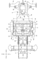
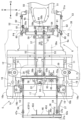
- FIG. 2 is a plan view of the vicinity of a front frame, a storage frame, and a transmission case when the front loader device is installed.
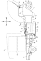
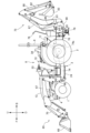
- FIG. 2 is a left side view of the electric tractor equipped with a front loader device and a backhoe device.
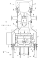
- FIG. 2 is a plan view of the front frame, storage frame, transmission case and the surrounding area when the front loader device and the backhoe device are installed.
- the machine body 3 has a front frame 4, a housing frame 5, and a transmission case 6.
- the front frame 4 is connected to a front portion 14 (see Figures 5 to 9) of the housing frame 5, and the transmission case 6 is connected to a rear portion 15 (see Figures 5 to 9) of the housing frame 5 to form the machine body 3.
- a first electric motor 11 and a second electric motor 12, which serve as power sources, are housed in the housing frame 5. In this case, the front frame 4 becomes the first front frame.
- a front axle case 7 is attached to the front frame 4, and the right and left front wheels 1 are attached to the front axle case 7.
- the right and left rear wheels 2 are attached to the transmission case 6.
- the driver's section 8, in which the operator sits, is provided across the accommodation frame 5 and the transmission case 6.
- the ROPS frame 9 is attached to the transmission case 6, extends upward, and is provided behind the driver's section 8.
- a battery 10 that supplies power to the electric motors 11, 12 is attached to the front frame 4, and a bonnet 13 that covers the battery 10 is provided.
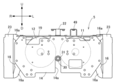
- the storage frame 5 has a front portion 14, a rear portion 15, a right side portion 16, a left side portion 16, and frames 17, 19, 20, 21, etc.
- the right and left side portions 16 of the storage frame 5 correspond to the right and left portions of the storage frame 5.
- the frame 17 is connected in the front-to-rear direction between the left and right central parts of the upper part of the rear surface of the front section 14 and the left and right central parts of the upper part of the front surface of the rear section 15.
- the frame 19 is connected in the left-to-right direction between the upper parts of the right and left lateral sections 16.
- the bracket 22 is connected between the frame 17 and the frame 19. In this case, the frame 17 becomes the upper frame of the storage frame 5.
- the electric motor 11 is provided on the left side of the recess 14a in the front part 14 and the opening 15a in the rear part 15 of the storage frame 5.
- the electric motor 12 is provided on the right side of the recess 14a in the front part 14 and the opening 15a in the rear part 15 of the storage frame 5.
- an upper mounting portion 16a is provided on the upper part of the front portion of the horizontal portion 16, facing diagonally upward, and a lower mounting portion 16a is provided on the lower part of the front portion of the horizontal portion 16, facing diagonally downward.
- the right mounting portion 23 is connected across the mounting portion 16a of the right side portion 16 of the storage frame 5.
- the left mounting portion 23 is connected across the mounting portion 16a of the left side portion 16 of the storage frame 5.
- a work device such as a front loader device 65 (see FIG. 14) is attached to the right and left mounting portions 23.
- the right and left inverters 24 are attached to the right and left lateral parts 16 of the storage frame 5, and are provided behind the mounting part 23. As described below, a speed change pedal 35 is provided on the driving part 8.
- the power of the battery 10 is supplied to the left inverter 24, and based on the operation of the gear shift pedal 35, the left inverter 24 converts the DC power of the battery 10 into AC power and supplies it to the electric motor 11, causing the electric motor 11 to operate in the forward direction (to move the electric tractor forward) and in the reverse direction (to move the electric tractor backward).
- FIG. 1 (Configuration of front frame and front axle case) As shown in Figures 1, 3 and 4, right and left front frames 4 are provided, and the front frames 4 are connected to the upper part of the front surface of the front portion 14 (see Figures 5 to 9) of the storage frame 5 and extend forward.
- Right and left front frames 26 are provided. At the lower part of the front surface of the front portion 14 (see Figures 5 to 9) of the storage frame 5, the rear part of the front frame 26 is connected to the lower part of the front frame 4, and the front part of the front frame 26 is connected to the front-to-rear middle part of the front frame 4. In this case, the front frame 26 becomes the second front frame.
- the battery 10 is attached to the top of the front frame 4, and the rear end of the battery 10 is located forward of the front ends of the electric motors 11, 12.
- the front axle case 7 front wheels 1 is attached to the lower front part of the front frame 4 in a rolling manner, and is located below the battery 10 and forward of the electric motors 11, 12.
- a flat cover 27 is attached across the right and left front frames 26.
- the front frames 26 and the cover 27 are inclined upwards toward the front, with the front portions of the front frame 26 and the cover 27 being higher than the rear portions of the front frame 26 and the cover 27.
- the cover 27 serves as a front wheel transmission shaft protection member.
- the right and left front frames 4, 26 and the cover 27 have the same left-right width W2.
- the left-right width W1 of the storage frame 5 is greater than the left-right width W2 of the right and left front frames 4, 26 and the cover 27.
- the output shaft 11b of the electric motor 11 is located at the position of an imaginary line L1 extending rearward from the left front frame 4, 26.
- the output shaft 12b of the electric motor 12 is located at the position of an imaginary line L2 extending rearward from the right front frame 4, 26.
- the left-right width W2 between the right and left front frames 4, 26 and the cover 27 is approximately the same as the left-right width (spacing) of the output shafts 11b, 12b of the electric motors 11, 12.
- the transmission case 6 has a front portion 6a, a rear portion 6b, and right and left rear axle cases 6c, and the right and left rear wheels 2 are attached to the rear axle cases 6c of the transmission case 6.
- the front portion 6a of the transmission case 6 is connected to the rear portion of the rear portion 15 of the housing frame 5, and the transmission case 6 is provided rearward of the electric motors 11, 12.
- the left-right width W1 of the housing frame 5 is greater than the left-right widths W3 and W4 of the front part 6a of the transmission case 6.
- the left-right widths W3 and W4 of the front part 6a of the transmission case 6 are greater than the left-right width W5 of the rear part 6b of the transmission case 6.
- a hydraulic multi-plate type running clutch (not shown), an auxiliary transmission (not shown), and a rear wheel differential (not shown) are provided inside the transmission case 6.
- the auxiliary transmission is configured as a gear shift type and is capable of changing speeds between high and low.
- the power of the output shaft 11b of the electric motor 11 is transmitted to the running clutch, from the running clutch to the auxiliary transmission, and from the auxiliary transmission to the rear wheels 2 via the rear wheel differential.
- the hydraulic multi-plate type running clutch, the auxiliary transmission, and the rear wheel differential form the transmission mechanism.
- the power branched off between the sub-transmission device and the rear wheel differential device is transmitted to the front wheel transmission shaft 31 (described below), from which it is transmitted to the front wheel differential device (not shown) inside the front axle case 7, and from which it is transmitted to the front wheels 1.
- the PTO shaft 28 is provided facing backward on the rear part 6b of the transmission case 6, and the mid-PTO shaft 29 is provided facing forward on the bottom of the rear part 6b of the transmission case 6.
- a hydraulic multi-plate type PTO clutch (not shown) and a PTO transmission system (not shown) are provided inside the transmission case 6.
- the power of the output shaft 12b of the electric motor 12 is transmitted to the PTO clutch, from the PTO clutch to the PTO transmission system, and from the PTO transmission system to the PTO shaft 28 and mid-PTO shaft 29.
- the PTO clutch and the PTO transmission system form the transmission mechanism.
- a pipe member 30 is connected in the front-to-rear direction between the rear portion 15 of the housing frame 5 and the front axle case 7.
- the front wheel transmission shaft 31 described above is provided inside the pipe member 30, and is connected between the inside of the transmission case 6 and the front wheel differential device of the front axle case 7.
- the pipe member 30 and the front wheel transmission shaft 31 are provided in the recess 14a in the front part 14 of the storage frame 5, and the front wheel transmission shaft 31 is provided in the opening 15a in the rear part 15 of the storage frame 5.
- the bearing portion 32 is provided in the opening 15a of the rear portion 15 of the storage frame 5.
- the front wheel transmission shaft 31 is supported by the bearing portion 32 and is supported by the rear portion 15 of the storage frame 5 via the bearing portion 32.
- the rear end of the pipe member 30 is attached to the bearing portion 32.
- the pipe member 30 and the front wheel transmission shaft 31 are provided at a height that overlaps with the electric motors 11, 12 in a side view. Specifically, the pipe member 30 and the front wheel transmission shaft 31 are provided between the output shafts 11b, 12b of the electric motors 11, 12 and the lower ends of the electric motors 11, 12 in a side view, and are provided above the frame 21 of the storage frame 5.
- the driver's section 8 is provided with a steering wheel 33 for steering the front wheels 1, a driver's seat 34, the aforementioned speed change pedal 35, right and left brake pedals 36, 37, a floor 38, etc.
- the support plate 42c is formed as a long, flat plate and is connected to the left-right center of the lower part of the partition wall 42a.
- the support plate 42d is formed as a flat plate and is connected to the left-right center of the partition wall 42a and extends rearward.
- a fully hydraulic power steering device 43 is attached to the lower part of the support plate 42c of the support frame 42, and the power steering device 43 is attached to the lower part of the steering handle 33 on the support frame 42.
- a steering shaft 33a extending downward from the base of the steering handle 33 is connected to the power steering device 43.
- the steering cylinder 44 is attached to the front axle case 7, and hydraulic oil is supplied to the steering cylinder 44 from the power steering device 43.
- the steering shaft 33a of the steering wheel 33 operates the power steering device 43, hydraulic oil is supplied from the power steering device 43 to the steering cylinder 44, and the steering cylinder 44 is actuated to steer the front wheels 1.
- the pillar frame 18 is formed in an arch shape when viewed from the front, and is disposed adjacent to the front side of the support frame 42 .
- right and left brackets 16b are provided on the front portions of the upper parts of the right and left horizontal portions 16 of the storage frame 5.
- the right and left lower portions of the pillar frame 18 are connected to the right and left brackets 16b of the storage frame 5 (horizontal portions 16), and the pillar frame 18 extends upward from the storage frame 5.
- the bonnet 13 is attached to the top of the pillar frame 18 so as to be pivotable about an axis along the left-right direction.
- the bonnet 13 can be opened and closed between a closed position (see Figure 1) and an open position above the closed position.
- a pipe member 46 is connected along the left-right direction to an upper portion of a support plate 42d of the support frame 42.
- a fulcrum shaft 47 is attached to the pipe member 46 so as to be rotatable about an axis P1 along the left-right direction, and a left portion of the fulcrum shaft 47 is rotatably supported by a bracket 42e connected to a partition wall portion 42a of the support frame 42.
- the boss portion 36a is connected to the top of the right brake pedal 36, and the boss portion 36a of the right brake pedal 36 is connected to the left portion of the fulcrum shaft 47, and the right brake pedal 36 extends downward from the fulcrum shaft 47.
- the right brake pedal 36 and the fulcrum shaft 47 swing together around the axis P1.
- the boss portion 37a is connected to the top of the left brake pedal 37, and the boss portion 37a of the left brake pedal 37 is rotatably attached to the left portion of the fulcrum shaft 47, and the left brake pedal 37 extends downward from the fulcrum shaft 47.
- the left brake pedal 37 swings around the axis P1 independently of the right brake pedal 36 and the fulcrum shaft 47.
- a right brake 50 capable of braking the right rear wheel 2 and a right brake 51 capable of braking the left rear wheel 2 are provided on the rear part 6b of the transmission case 6.
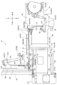
- a right linking mechanism 52 is connected between the right brake pedal 36 and the right brake 50 as described below.
- a left linking mechanism 53 is connected between the left brake pedal 37 and the left brake 51 as described below.
- the right linking rod 54 is connected between the arm 47a of the fulcrum shaft 47 and the arm 56a of the pipe member 56.
- the left linking rod 54 is connected between the arm 37b of the left brake pedal 37 and the arm 55a of the linking shaft 55.
- two pipe members 64 are connected to an upper side of the rear part 6b of the transmission case 6 with a gap therebetween in the left-right direction.
- a linking shaft 58 is attached to the pipe members 64 so as to be rotatable about an axis P3 along the left-right direction.
- An arm 58a is connected to the left end of the linking shaft 58, and an arm 58b is connected to the left-right center of the linking shaft 58 (the portion between the two pipe members 64).
- the right connecting rod 61 is provided behind the right portion of the front part 6a of the transmission case 6 and laterally outward of the right lateral part of the rear part 6b of the transmission case 6 along the vertical direction.
- the left connecting rod 61 is provided rearward of the left portion of the front portion 6a of the transmission case 6 and laterally outward of the left lateral portion of the rear portion 6b of the transmission case 6 along the vertical direction.
- the right linking rod 62 is connected in the front-to-rear direction between the right crank member 60 and the operating part 50a of the right brake 50.
- the left linking rod 62 is connected in the front-to-rear direction between the left crank member 60 and the operating part 51a of the left brake 51.
- the right linking rod 57 is operated forward
- the pipe member 59 is operated in the counterclockwise direction in FIG. 10
- the right linking rod 61 is operated upward
- the right crank member 60 is operated in the counterclockwise direction in FIG. 10
- the right linking rod 62 is operated backward
- the operating part 50a of the right brake 50 is operated backward, thereby applying the brake to the right brake 50.
- the boom 67 is attached to the upper end of the base 66 so as to be able to swing up and down, and a boom cylinder 69 that swings the boom 67 up and down is connected between the base 66 and the boom 67.
- the bucket 68 is attached to the front end of the right and left boom 67 so as to be able to swing up and down, and a bucket cylinder 70 that swings the bucket 68 up and down is connected between the boom 67 and the bucket 68.
- the swing bracket 80 is attached to the base 76 so that it can swing left and right, and a swing cylinder 85 that swings the swing bracket 80 left and right is connected between the base 76 and the swing bracket 80.
- An arm 82 is attached to the boom 81 so as to be swingable back and forth, and an arm cylinder 87 which swings the arm 82 back and forth is connected between the boom 81 and the arm 82 .
- a bucket 83 is attached to the arm 82 so as to be swingable back and forth, and a bucket cylinder 88 which swings the bucket 83 back and forth is connected between the arm 82 and the bucket 83 .
- the base 66 of the front loader device 65 is connected to the mounting portion 23 of the storage frame 5, as shown in Figures 14 to 17, the front ends of the right front and rear frames 73, 74 are connected to the outer lateral surface of the right base 66 of the front loader device 65, and the rear ends of the right front and rear frames 73, 74 are connected to the right rear axle case 6c of the transmission case 6.
- the front ends of the left front and rear frames 73, 74 are connected to the outer lateral surface of the left base 66 of the front loader device 65, and the rear ends of the left front and rear frames 73, 74 are connected to the left rear axle case 6c of the transmission case 6.
- the right and left rear axle cases 6c of the transmission case 6 are the parts to which the right and left running devices (rear wheels 2) of the transmission case 6 are attached.
- the base 66 of the front loader device 65 is sandwiched between the mounting portion 23 and the front ends of the front and rear frames 73, 74, and the mounting portion 23, the front ends of the front and rear frames 73, 74, and the base 66 of the front loader device 65 are fastened together.
- right and left rear mounting parts 74a are provided at the rear of the right and left front and rear frames 74.
- the base 76 of the backhoe device 75 is attached to the rear mounting parts 74a of the front and rear frames 74.
- a control valve unit 71 provided with a plurality of electromagnetically operated control valves is attached to the front of right front and rear frames 73, 74.
- An operation lever 72 for operating the control valve unit 71 is provided to the right of the driving section 8.
- the control valve unit 71 serves as the control valve.
- the electric motor 12 drives a hydraulic pump (not shown), and hydraulic oil from the hydraulic pump is supplied to a control valve unit 71, which then supplies and discharges the hydraulic oil to the boom cylinder 69 and bucket cylinder 70 of the front loader device 65.
- the hydraulic oil from the hydraulic pump is also supplied to hydraulic equipment (not shown) such as the power steering device 43 (see FIG. 11) equipped on the electric tractor, and the hydraulic equipment such as the power steering device 43 operates using the supplied hydraulic oil.
- the operator in the driver's seat 34 can operate the control valve of the control valve unit 71 by operating the operating lever 72 to operate the boom 67 and bucket 68 of the front loader device 65.
- the worker When operating the backhoe device 75 , the worker switches the hydraulic pump to a state in which hydraulic oil is supplied to the backhoe device 75 .
- An operator sits on the work seat 77 of the backhoe device 75 and lowers the right and left outriggers 79 to touch the ground.
- the operator on the work seat 77 can operate the swing bracket 80, boom 81, arm 82, and bucket 83 of the backhoe device 75 by operating the operation lever 78 to operate a control valve (not shown) of the backhoe device 75.
- the hydraulic pump may be configured to be driven by an electric motor (not shown) separate from the electric motors 11 and 12 .
- the hydraulic pump may be configured to be driven by the electric motor 11.
- the control valve unit 71 may be attached to the left front and rear frames 73, 74.
- the right linking rod 57 may be provided in the front-to-rear direction between the raised portion 38a of the floor 38 and the storage frame 5
- the left linking rod 57 may be provided in the front-to-rear direction between the left portion of the floor 38 and the left lateral portion 16 of the storage frame 5.
- the raised portion 38a of the floor 38 may be eliminated, and the entire surface of the floor 38 may be formed flat.
- the right and left brakes 50, 51 may be eliminated, and a single brake (not shown) capable of braking both the right and left rear wheels 2 may be provided.
- the electric motor 11 and 12 When the electric motors 11 and 12 are arranged side by side in the left-right direction, the electric motor 11 may be provided on the right and the electric motor 12 may be provided on the left.
- the battery 10 , the electric motors 11 and 12 , and the housing frame 5 may be arranged so that the rear end of the battery 10 is located slightly rearward of the front ends of the electric motors 11 and 12 .
- One electric motor 11 may be accommodated in the accommodation frame 5 .
- the left-right width W1 of the housing frame 5 and the left-right width W3 of the front portion 6a of the transmission case 6 may be substantially the same.
- the electric motor 12 may be attached to a portion separate from the housing frame 5.
- Two electric motors 11 may be accommodated in the accommodation frame 5 side by side in the left-right direction. According to this configuration, one electric motor 11 serves as the first electric motor 11, and the other electric motor 11 serves as the second electric motor 11. In this case, the electric motor 11 may be attached to a portion other than the accommodation frame 5.
- One electric motor 12 may be accommodated in the accommodation frame 5 .
- the left-right width W1 of the accommodation frame 5 and the left-right width W3 of the front portion 6a of the transmission case 6 may be substantially the same.
- the electric motor 11 may be attached to a portion separate from the accommodation frame 5.
- Two electric motors 12 may be accommodated in the accommodation frame 5 side by side in the left-right direction. According to this configuration, one electric motor 12 serves as the first electric motor 12, and the other electric motor 12 serves as the second electric motor 12. In this case, the electric motor 11 may be attached to a portion other than the accommodation frame 5.
- the front portions of the electric motors 11 , 12 may be connected to the front portion 14 of the storage frame 5 . According to this configuration, the casings of the electric motors 11, 12 become part of the accommodating frame 5, thereby improving the rigidity of the accommodating frame 5.
- the front and rear frames 73 , 74 may be connected across the mounting portion 23 of the storage frame 5 and the rear axle case 6 c of the transmission case 6 .
- the backhoe device 75 may be attached to the rear mounting portion 74a of the front and rear frames 74.
- the vehicle may be configured as a rear two-wheel drive type instead of a four-wheel drive type. According to this configuration, the pipe member 30, the front wheel transmission shaft 31, the bearing portion 32, the opening 15b in the rear portion 15 and the recess 14a in the front portion 14 of the storage frame 5, etc. are eliminated.
- right and left crawler-type running devices may be attached to the transmission case 6 .
- the electric tractor may be configured as a hybrid type electric tractor equipped with an engine (not shown) and electric motors 11, 12 as a power source.
- the driving section 8 having the floor 38 thereunder is provided.
- the electric motors 11, 12 are provided below the floor 38 and generate power for traveling or power and hydraulic pressure for operating the installed work devices (front loader device 65 and backhoe device 75).
- the storage frame 5 is provided below the floor 38 and stores the electric motors 11, 12. The floor 38 is attached to the storage frame 5.
- the widths W3, W4 in the left-right direction of the front part 6a of the transmission case 6 are smaller than the width W1 in the left-right direction of the housing frame 5 and larger than the width W5 in the left-right direction of the rear part 6b of the transmission case 6.
- the linking mechanisms 52, 53 extend from between the raised portion 38a and the housing frame 5 to a position above the rear portion 6b of the transmission case 6.
- the upper and lower portions are provided behind the front portion 6a of the transmission case 6 and laterally outward of the rear portion 6b of the transmission case 6.
Landscapes
- Engineering & Computer Science (AREA)
- Chemical & Material Sciences (AREA)
- Combustion & Propulsion (AREA)
- Transportation (AREA)
- Mechanical Engineering (AREA)
- Body Structure For Vehicles (AREA)
Abstract
電動トラクタは、下部にフロア38を有する運転部と、フロア38の下方に設けられ、走行用の動力又は装備された作業装置を作動させる動力と油圧とを発生する電動モータ11,12と、フロア38の下方に設けられ、電動モータ11,12を収容する収容フレーム5とが備えられる。フロア38が、収容フレーム5に取り付けられる。
Description
本発明は、電動トラクタにおいて運転部の構成に関する。
トラクタでは、特許文献1に開示されているように、動力源としてのエンジンが設けられたものがある。
特許文献1では、前輪及び後輪が設けられた機体に、作業者が搭乗する運転部が設けられている。エンジンが運転部の前方に設けられ、前輪が取り付けられた前車軸ケースがエンジンの下方に設けられており、後輪が取り付けられたミッションケースが運転部の下方に設けられている。伝動軸が、エンジンとミッションケースとに亘って接続され、前輪伝動軸が、ミッションケースと前車軸ケースとに亘って接続されている。
特許文献1では、前輪及び後輪が設けられた機体に、作業者が搭乗する運転部が設けられている。エンジンが運転部の前方に設けられ、前輪が取り付けられた前車軸ケースがエンジンの下方に設けられており、後輪が取り付けられたミッションケースが運転部の下方に設けられている。伝動軸が、エンジンとミッションケースとに亘って接続され、前輪伝動軸が、ミッションケースと前車軸ケースとに亘って接続されている。
トラクタでは、走行用の動力を発生する電動モータや、装備された作業装置を作動させる動力と油圧とを発生する電動モータを装備した電動トラクタが提案されている。
本発明は、電動トラクタにおいて運転部が無理なく設けられるように構成することを目的としている。
本発明は、電動トラクタにおいて運転部が無理なく設けられるように構成することを目的としている。
本発明の電動トラクタは、下部にフロアを有する運転部と、前記フロアの下方に設けられ、走行用の動力又は装備された作業装置を作動させる動力と油圧とを発生する電動モータと、前記フロアの下方に設けられ、前記電動モータを収容する収容フレームとが備えられ、前記フロアが、前記収容フレームに取り付けられている。
本発明によると、重量物である電動モータが、運転部のフロアの下方という低い位置に配置され、電動トラクタの前後中央に近い位置に配置されるので、電動トラクタの低重心化を図ることができ、電動トラクタとして好ましい重量バランスが得られて、電動トラクタの走行性能が向上する。
本発明によると、電動モータを収容する収容フレームが設けられ、収容フレームが運転部のフロアの下方に設けられている。収容フレームは、重量物である電動モータを収容するものなので、十分な強度を有するように構成される。
本発明によると、運転部のフロアが収容フレームに取り付けられて、運転部(フロア)が収容フレームにより十分な強度で支えられる。
本発明によると、運転部のフロアが収容フレームに取り付けられて、運転部(フロア)が収容フレームにより十分な強度で支えられる。
本発明において、右及び左の後の走行装置が取り付けられ、前記電動モータの動力が伝達される伝動機構が内部に設けられ、前記収容フレームの後部に連結されたミッションケースが備えられ、前記運転部が、前記ミッションケースに取り付けられていると好適である。
ミッションケースは、後の走行装置が取り付けられるので、十分な強度を有するように構成される。
本発明によると、ミッションケースが収容フレームの後部に連結されており、十分な強度を有する収容フレームと十分な強度を有するミッションケースとが連結されることにより、電動トラクタの全体の剛性が向上する。
本発明によると、運転部がミッションケースに取り付けられて、運転部(フロア)が収容フレーム及びミッションケースにより十分な強度で支えられる。
本発明によると、ミッションケースが収容フレームの後部に連結されており、十分な強度を有する収容フレームと十分な強度を有するミッションケースとが連結されることにより、電動トラクタの全体の剛性が向上する。
本発明によると、運転部がミッションケースに取り付けられて、運転部(フロア)が収容フレーム及びミッションケースにより十分な強度で支えられる。
本発明において、前記フロアと前記収容フレームとの間及び前記運転部と前記ミッションケースとの間に設けられ、弾性変形可能な支持部が備えられ、前記フロアが、前記支持部を介して前記収容フレームに取り付けられ、前記運転部が、前記支持部を介して前記ミッションケースに取り付けられていると好適である。
本発明によると、運転部(フロア)が、弾性変形可能な支持部を介して収容フレーム及びミッションケースに支えられ、走行時等の振動の運転部への伝達が支持部により抑えられるので、運転部に搭乗する作業者の快適性を向上させることができる。
本発明において、前記収容フレームの右部の上部分と左部の上部分とに亘って、左右方向に沿って連結されたフレームが備えられ、前記フロアと前記収容フレームとの間の前記支持部が、前記フレームに取り付けられていると好適である。
本発明によると、フレームが、収容フレームの右部の上部分と左部の上部分とに亘って左右方向に沿って連結されているので、収容フレームが補強され、収容フレームの剛性が向上する。
本発明によると、支持部が収容フレームのフレームに取り付けられており、収容フレームのフレームが支持部の取付部材に兼用されるので、構造の簡素化を図ることができる。
本発明によると、支持部が収容フレームのフレームに取り付けられており、収容フレームのフレームが支持部の取付部材に兼用されるので、構造の簡素化を図ることができる。
本発明において、前記フロアに取り付けられ、前記フロアから上方に向けて延出された支持フレームが備えられ、操向操作を行う操縦ハンドルが、前記支持フレームに取り付けられていると好適である。
本発明によると、支持フレームがフロアに取り付けられ、操縦ハンドルが支持フレームに取り付けられている。これにより、支持フレームが収容フレームにより十分な強度で支えられ、操縦ハンドルが支持フレームを介して収容フレームにより十分な強度で支えられる。
本発明において、前記操縦ハンドルによる操向操作を補助するパワーステアリング装置が、前記支持フレームにおける前記操縦ハンドルの下方の部分に取り付けられていると好適である。
本発明によると、操縦ハンドルが支持フレームに取り付けられ、パワーステアリング装置が支持フレームにおける操縦ハンドルの下方の部分に取り付けられることにより、操縦ハンドルに加えて、パワーステアリング装置が支持フレームを介して収容フレームにより十分な強度で支えられる。
本発明において、前記収容フレームに取り付けられ、前記収容フレームから上方に向けて延出されたピラーフレームと、前記ピラーフレームの前方に設けられたボンネットとが備えられ、前記ボンネットが、閉位置と前記閉位置よりも上側の開位置とに亘って開閉可能に、前記ピラーフレームに取り付けられていると好適である。
本発明によると、ピラーフレームが収容フレームに取り付けられ、ボンネットがピラーフレームに開閉可能に取り付けられている。これにより、ピラーフレームが収容フレームにより十分な強度で支えられ、ボンネットがピラーフレームを介して収容フレームにより十分な強度で支えられる。
本発明において、前記フロアに取り付けられ、前記フロアから上方に向けて延出された支持フレームと、走行用のブレーキとが備えられ、前記ブレーキを操作するブレーキペダルが、前記支持フレームに取り付けられていると好適である。
本発明によると、支持フレームがフロアに取り付けられ、ブレーキペダルが支持フレームに取り付けられている。これにより、支持フレームが収容フレームにより十分な強度で支えられ、ブレーキペダルが支持フレームを介して収容フレームにより十分な強度で支えられる。
本発明において、右及び左の後の走行装置が取り付けられ、前記電動モータの動力が伝達される伝動機構が内部に設けられ、前記収容フレームの後部に連結されたミッションケースと、前記ミッションケースに設けられ、前記走行装置を制動可能な前記ブレーキと、前記ブレーキペダルと前記ブレーキとに亘って接続され、前記ブレーキペダルの操作を前記ブレーキに伝達して、前記ブレーキを制動操作する連係機構とが備えられ、前記連係機構が、前記フロアと前記収容フレームとの間に、前後方向に沿って設けられていると好適である。
ミッションケースは、後の走行装置が取り付けられるので、十分な強度を有するように構成される。
本発明によると、ミッションケースが収容フレームの後部に連結されており、十分な強度を有する収容フレームと十分な強度を有するミッションケースとが連結されることにより、電動トラクタの全体の剛性が向上する。
本発明によると、ミッションケースが収容フレームの後部に連結されており、十分な強度を有する収容フレームと十分な強度を有するミッションケースとが連結されることにより、電動トラクタの全体の剛性が向上する。
本発明によると、ブレーキがミッションケースに設けられた場合、ブレーキペダルとブレーキとに亘って接続された連係機構が、運転部のフロアと収容フレームとの間に前後方向に沿って設けられている。これにより、運転部のフロアと収容フレームとの間の空間が連係機構の配置に有効に利用されるので、連係機構の配置のコンパクト化を図ることができる。
本発明において、前記フロアの左右中央部分に、前記フロアの他の部分よりも上方に向けて盛り上がるように屈曲する盛り上がり部が、前後方向に沿って形成され、前記連係機構が、前記盛り上がり部と前記収容フレームとの間に、前後方向に沿って設けられていると好適である。
本発明によると、盛り上がり部が運転部のフロアの左右中央部分に前後方向に沿って設けられており、運転部のフロアの盛り上がり部と収容フレームとに間に、前後方向に沿ってトンネル状の空間が形成される。これにより、連係機構が運転部のフロアの盛り上がり部と収容フレームとに間に無理なく設けられるのであり、連係機構の配置のコンパクト化を図るという面で有利である。
作業者が運転部の運転席に着座して右足及び左足をフロアに置いた場合や、作業者が運転部のフロアに立っている場合、運転部のフロアの左右中央部分は、作業者の右足及び左足の間に位置していることが多い。
これにより、盛り上がり部が運転部のフロアの左右中央部分に前後方向に沿って設けられても、運転部のフロアの盛り上がり部が作業者の作業の妨げになることはない。
これにより、盛り上がり部が運転部のフロアの左右中央部分に前後方向に沿って設けられても、運転部のフロアの盛り上がり部が作業者の作業の妨げになることはない。
本発明において、第1の前記電動モータと、第2の前記電動モータとが備えられ、第1の前記電動モータと第2の前記電動モータとが、左右方向に沿って並べて前記収容フレームに収容され、前記収容フレームの左右方向の横幅は、前記ミッションケースの左右方向の横幅よりも大きく、前記連係機構は、前記盛り上がり部と前記収容フレームとの間から、前記ミッションケースの上方の位置に延出され、前記連係機構は、前記ミッションケースの上方の位置と前記ミッションケースの横側部の上方の位置とに亘って設けられた左右部分と、前記左右部分と前記ミッションケースの横側部の位置とに亘って、前記ミッションケースの横外方に上下方向に沿って設けられた上下部分と、前記上下部分と前記ブレーキの操作部とに亘って前後方向に沿って接続された前後部分とを有していると好適である。
本発明によると、第1の電動モータと第2の電動モータとが備えられた場合、第1の電動モータ及び第2の電動モータが左右方向に沿って並べて設けられることにより、第1の電動モータ及び第2の電動モータが、前後方向で略同じ位置に設けられ、上下方向で略同じ高さに設けられるので、電動トラクタにおいて好ましい重量バランスが得られ、電動トラクタの走行性能の向上の面で有利である。
本発明によると、第1の電動モータ及び第2の電動モータが、左右方向に沿って並べて収容フレームに収容されるので、収容フレームの前後方向の長さが抑えられる。これに対して、収容フレームの左右方向の横幅は大きくなる。
本発明によると、後の走行装置が取り付けられたミッションケースが、左右方向の横幅の大きな収容フレームの後部に連結され後方に向けて延出されることによって、収容フレームは、後の走行装置と干渉することなく、側面視で後の走行装置の前方に無理なく設けられる。
本発明によると、連係機構は、運転部のフロアの盛り上がり部と収容フレームとの間から、ミッションケースの上方の位置に延出され、ミッションケースの横側部の上方の位置に延出され(左右部分)、ミッションケースの横側部に沿って下方に延出され(上下部分)、後方に向けて延出されて(前後部分)、ブレーキの操作部に接続されている。
これにより、連係機構が収容フレーム及びミッションケースに沿って配置されるので、連係機構の配置のコンパクト化を図るという面で有利である。
これにより、連係機構が収容フレーム及びミッションケースに沿って配置されるので、連係機構の配置のコンパクト化を図るという面で有利である。
本発明において、前記ミッションケースの前部の左右方向の横幅は、前記収容フレームの左右方向の横幅よりも小さく、且つ、前記ミッションケースの後部の左右方向の横幅よりも大きく、前記連係機構は、前記盛り上がり部と前記収容フレームとの間から、前記ミッションケースの後部の上方の位置に延出され、前記上下部分が、前記ミッションケースの前部の後方、且つ、前記ミッションケースの後部の横外方に設けられていると好適である。
本発明によると、ミッションケースの前部が収容フレームの後部に連結される場合、ミッションケースの前部の左右方向の横幅は、ミッションケースの後部の左右方向の横幅よりも大きい。
これにより、収容フレームの左右方向の横幅、ミッションケースの前部の左右方向の横幅、ミッションケースの後部の左右方向の横幅が、順番に小さくなるので、収容フレームとミッションケースとの連結部分(ミッションケースの前部)の剛性が向上する。
これにより、収容フレームの左右方向の横幅、ミッションケースの前部の左右方向の横幅、ミッションケースの後部の左右方向の横幅が、順番に小さくなるので、収容フレームとミッションケースとの連結部分(ミッションケースの前部)の剛性が向上する。
本発明によると、連係機構は、運転部のフロアの盛り上がり部と収容フレームとの間から、ミッションケースの後部の上方の位置に延出され、ミッションケースの前部の後方でミッションケースの後部の横外方を通って延出される(上下部分)。
これにより、連係機構が、ミッションケースの前部及び後部に沿って配置されるのであり、連係機構の配置のコンパクト化を図るという面で有利である。
これにより、連係機構が、ミッションケースの前部及び後部に沿って配置されるのであり、連係機構の配置のコンパクト化を図るという面で有利である。
本発明において、右の前記走行装置を制動可能な右の前記ブレーキと、左の前記走行装置を制動可能な左の前記ブレーキと、右の前記ブレーキペダルと、左の前記ブレーキペダルと、右の前記ブレーキペダルと右の前記ブレーキとに亘って接続された右の前記連係機構と、左の前記ブレーキペダルと左の前記ブレーキとに亘って接続された左の前記連係機構とが備えられていると好適である。
本発明によると、右及び左のブレーキ、右及び左のブレーキペダル、右及び左の連係機構が備えられている。作業者は、右のブレーキペダルを踏み操作することによって、右のブレーキにより右の後の走行装置に制動を掛けることができ、左のブレーキペダルを踏み操作することによって、左のブレーキにより左の後の走行装置に制動を掛けることができる。
本発明によると、右及び左のブレーキ、右及び左のブレーキペダル、右及び左の連係機構が備えられた電動トラクタに適した構成が得られる。
本発明によると、右及び左のブレーキ、右及び左のブレーキペダル、右及び左の連係機構が備えられた電動トラクタに適した構成が得られる。
図1~図17は、電動トラクタを示しており、図1~図17において、Fは前方向を示し、Bは後方向を示し、Uは上方向を示し、Dは下方向を示し、Rは右方向を示し、Lは左方向を示している。
(電動トラクタの全体構成)
図1及び図2に示すように、右及び左の前輪1が、機体3の前部に設けられ、右及び左の後輪2が、機体3の後部に設けられて、機体3が前輪1及び後輪2により支えられている。この場合、後輪2が後の走行装置となる。
図1及び図2に示すように、右及び左の前輪1が、機体3の前部に設けられ、右及び左の後輪2が、機体3の後部に設けられて、機体3が前輪1及び後輪2により支えられている。この場合、後輪2が後の走行装置となる。
機体3は、前フレーム4 収容フレーム5及びミッションケース6を有している。収容フレーム5の前部14(図5~図9参照)に前フレーム4が連結され、収容フレーム5の後部15(図5~図9参照)にミッションケース6が連結されて、機体3が構成されている。動力源としての第1の電動モータ11及び第2の電動モータ12が、収容フレーム5に収容されている。この場合、前フレーム4が第1前フレームとなる。
前車軸ケース7が、前フレーム4に取り付けられており、右及び左の前輪1が、前車軸ケース7に取り付けられている。右及び左の後輪2が、ミッションケース6に取り付けられている。
作業者が搭乗する運転部8が、収容フレーム5及びミッションケース6に亘って設けられている。ロプスフレーム9が、ミッションケース6に取り付けられ上方に向けて延出されて、運転部8の後方に設けられている。電動モータ11,12に電力を供給するバッテリ10が、前フレーム4に取り付けられており、バッテリ10を覆うボンネット13が設けられている。
(収容フレームの構成)
図5~図9に示すように、収容フレーム5は、前部14、後部15、右の横部16、左の横部16、フレーム17,19,20,21等を有している。この場合、収容フレーム5の右及び左の横部16が、収容フレーム5の右部及び左部となる。
図5~図9に示すように、収容フレーム5は、前部14、後部15、右の横部16、左の横部16、フレーム17,19,20,21等を有している。この場合、収容フレーム5の右及び左の横部16が、収容フレーム5の右部及び左部となる。
前部14及び後部15は、上下方向及び左右方向に沿った平板状に構成されている。右及び左の横部16は、上下方向及び前後方向に沿った平板状で少し湾曲して構成されている。前部14の後面部の右部分及び左部分に、横部16の前部分が連結され、後部15の前面部の右部分及び左部分に、横部16の後部分が連結されている。
フレーム17が、前部14の後面部の上部分の左右中央部分と、後部15の前面部の上部分の左右中央部分とに亘って前後方向に沿って連結されている。フレーム19が、右及び左の横部16の上部分に亘って左右方向に沿って連結されている。ブラケット22が、フレーム17とフレーム19とに亘って連結されている。この場合、フレーム17が収容フレーム5の上フレームとなる。
右及び左のフレーム20が、右及び左の横部16の下部分に、前後方向に沿って連結されている。フレーム21が、右及び左のフレーム20に亘って、左右方向に沿って連結されている。前部14の下部分の左右中央部分に、下向きに開放され上方に向いた凹部14aが設けられている。後部15の左右中央部分に、開口部15aが開口されている。この場合、フレーム21が収容フレーム5の下フレームとなる。
(収容フレームにおける電動モータの収容の構成)
図5~図8に示すように、電動モータ11,12が、収容フレーム5の内部(前部14と後部15との間、右及び左の横部16の間、フレーム17,19とフレーム21との間)に、左右方向に沿って並べて設けられている。電動モータ11,12は、同じ出力を有する同じものである。
図5~図8に示すように、電動モータ11,12が、収容フレーム5の内部(前部14と後部15との間、右及び左の横部16の間、フレーム17,19とフレーム21との間)に、左右方向に沿って並べて設けられている。電動モータ11,12は、同じ出力を有する同じものである。
電動モータ11の後端部のフランジ部11aが、収容フレーム5の後部15の前面部の左部分に連結されている。電動モータ12の後端部のフランジ部12aが、収容フレーム5の後部15の前面部の右部分に連結されている。電動モータ11,12の出力軸11b,12bが、電動モータ11,12のフランジ部11a,12aの位置に、後方に向けて前後方向に沿って設けられている。
収容フレーム5の内部において、電動モータ11が収容フレーム5の前部14の凹部14a及び後部15の開口部15aに対して左側に設けられている。電動モータ12が収容フレーム5の前部14の凹部14a及び後部15の開口部15aに対して右側に設けられている。
図3に示すように、平板状のカバー25が、収容フレーム5の底部である右及び左の横部16の下部分に亘って取り付けられ、収容フレーム5の前部14及び後部15の下部分に亘って取り付けられている。この場合、カバー25が電動モータ保護部材となる。
(作業装置を取り付ける為の取付部及びインバータの構成)
図5~図9に示すように、収容フレーム5の右及び左の横部16において、上の取付部16aが横部16の前部分の上部分に斜め上向きに設けられており、下の取付部16aが横部16の前部分の下部分に斜め下向きに設けられている。
図5~図9に示すように、収容フレーム5の右及び左の横部16において、上の取付部16aが横部16の前部分の上部分に斜め上向きに設けられており、下の取付部16aが横部16の前部分の下部分に斜め下向きに設けられている。
右の取付部23が、収容フレーム5の右の横部16の取付部16aに亘って連結されている。左の取付部23が、収容フレーム5の左の横部16の取付部16aに亘って連結されている。後述するように、フロントローダ装置65(図14参照)等の作業装置が右及び左の取付部23に取り付けられる。
図1~図4に示すように、右及び左のインバータ24が、収容フレーム5の右及び左の横部16に取り付けられており、取付部23の後方に設けられている。後述するように、変速ペダル35が、運転部8に設けられている。
バッテリ10の電力が左のインバータ24に供給され、変速ペダル35の操作に基づいて、左のインバータ24においてバッテリ10の直流電力が交流電力に変換されて電動モータ11に供給され、電動モータ11が正転作動(電動トラクタの前進)及び逆転作動(電動トラクタの後進)する。
バッテリ10の電力が右のインバータ24に供給され、右のインバータ24においてバッテリ10の直流電力が交流電力に変換されて電動モータ12に供給され、電動モータ12が作動する。電動モータ12は、後述するように油圧ポンプ(図示せず)を駆動するので、正転作動し、逆転作動は行わない。
(前フレーム及び前車軸ケースの構成)
図1,3,4に示すように、右及び左の前フレーム4が設けられており、前フレーム4が収容フレーム5の前部14(図5~図9参照)の前面部の上部分に連結されて、前方に向けて延出されている。
図1,3,4に示すように、右及び左の前フレーム4が設けられており、前フレーム4が収容フレーム5の前部14(図5~図9参照)の前面部の上部分に連結されて、前方に向けて延出されている。
右及び左の前フレーム26が設けられている。収容フレーム5の前部14(図5~図9参照)の前面部の下部分において、前フレーム4の下方の部分に、前フレーム26の後部が連結され、前フレーム26の前部が前フレーム4の前後中間部に連結されている。この場合、前フレーム26が第2前フレームとなる。
バッテリ10が、前フレーム4の上部に取り付けられており、バッテリ10の後端部が電動モータ11,12の前端部よりも前側に設けられている。前車軸ケース7(前輪1)が、前フレーム4の前部の下部にローリング可能に取り付けられており、バッテリ10の下方に設けられ、電動モータ11,12よりも前側に設けられている。
平板状のカバー27が、右及び左の前フレーム26に亘って取り付けられている。前フレーム26及びカバー27は、側面視で、前フレーム26及びカバー27の前部が前フレーム26及びカバー27の後部よりも高い前上がり傾斜姿勢となっている。この場合、カバー27が前輪伝動軸保護部材となる。
図4に示すように、右及び左の前フレーム4,26とカバー27とは、同じ左右方向の横幅W2を有している。収容フレーム5の左右方向の横幅W1は、右及び左の前フレーム4,26とカバー27との左右方向の横幅W2よりも大きい。
平面視で、左の前フレーム4,26から後方に延出された仮想線L1の位置に、電動モータ11の出力軸11bが位置している。右の前フレーム4,26から後方に延出された仮想線L2の位置に、電動モータ12の出力軸12bが位置している。これにより、右及び左の前フレーム4,26とカバー27との左右方向の横幅W2と、電動モータ11,12の出力軸11b,12bの左右方向の横幅(間隔)とは、ほぼ同じである。
(ミッションケースの構成)
図3及び図4に示すように、ミッションケース6は、前部6aと、後部6bと、右及び左の後車軸ケース6cとを有しており、右及び左の後輪2が、ミッションケース6の後車軸ケース6cに取り付けられている。ミッションケース6の前部6aが、収容フレーム5の後部15の後面部に連結されており、ミッションケース6は電動モータ11,12よりも後側に設けられている。
図3及び図4に示すように、ミッションケース6は、前部6aと、後部6bと、右及び左の後車軸ケース6cとを有しており、右及び左の後輪2が、ミッションケース6の後車軸ケース6cに取り付けられている。ミッションケース6の前部6aが、収容フレーム5の後部15の後面部に連結されており、ミッションケース6は電動モータ11,12よりも後側に設けられている。
収容フレーム5の左右方向の横幅W1は、ミッションケース6の前部6aの左右方向の横幅W3,W4よりも大きい。ミッションケース6の前部6aの左右方向の横幅W3,W4は、ミッションケース6の後部6bの左右方向の横幅W5よりも大きい。
油圧多板型式の走行クラッチ(図示せず)、副変速装置(図示せず)及び後輪デフ装置(図示せず)が、ミッションケース6の内部に設けられている。副変速装置は、ギヤ変速式に構成されて、高低2段に変速可能である。電動モータ11の出力軸11bの動力が、走行クラッチに伝達され、走行クラッチから副変速装置に伝達され、副変速装置から後輪デフ装置を介して後輪2に伝達される。この場合、油圧多板式の走行クラッチ、副変速装置及び後輪デフ装置が伝動機構となる。
ミッションケース6の内部において、副変速装置と後輪デフ装置との間から分岐した動力が、後述する前輪伝動軸31に伝達され、前輪伝動軸31から前車軸ケース7の内部の前輪デフ装置(図示せず)に伝達され、前輪デフ装置から前輪1に伝達される。
PTO軸28が、ミッションケース6の後部6bに後向きに設けられ、ミッドPTO軸29が、ミッションケース6の後部6bの底部に、前向きに設けられている。油圧多板型式のPTOクラッチ(図示せず)及びPTO伝動系(図示せず)が、ミッションケース6の内部に設けられている。電動モータ12の出力軸12bの動力が、PTOクラッチに伝達され、PTOクラッチからPTO伝動系に伝達されて、PTO伝動系からPTO軸28及びミッドPTO軸29に伝達される。この場合、PTOクラッチ及びPTO伝動系が伝動機構となる。
電動トラクタにおいて、ロータリ耕耘装置(図示せず)等の作業装置が機体3の後部に取り付けられた場合、PTO軸28の動力が作業装置に伝達される。モーア(図示せず)等の作業装置が、機体3の下部で前輪1及び後輪2の間に取り付けられた場合、ミッドPTO軸29の動力が作業装置に伝達される。
(前輪伝動軸の構成)
図3及び図4に示すように、パイプ部材30が、収容フレーム5の後部15と前車軸ケース7とに亘って、前後方向に沿って接続されている。前述の前輪伝動軸31が、パイプ部材30の内部に設けられ、ミッションケース6の内部と前車軸ケース7の前輪デフ装置とに亘って接続されている。
図3及び図4に示すように、パイプ部材30が、収容フレーム5の後部15と前車軸ケース7とに亘って、前後方向に沿って接続されている。前述の前輪伝動軸31が、パイプ部材30の内部に設けられ、ミッションケース6の内部と前車軸ケース7の前輪デフ装置とに亘って接続されている。
図7,8,9に示すように、収容フレーム5において、パイプ部材30及び前輪伝動軸31は収容フレーム5の前部14の凹部14aに設けられ、前輪伝動軸31は収容フレーム5の後部15の開口部15aに設けられている。
軸受け部32が、収容フレーム5の後部15の開口部15aに設けられている。前輪伝動軸31が、軸受け部32により支えられて、軸受け部32を介して収容フレーム5の後部15に支えられている。パイプ部材30の後端部が、軸受け部32に取り付けられている。
図3,4,7,8に示すように、パイプ部材30及び前輪伝動軸31は、平面視で右及び左の前フレーム4,26の間に設けられ、カバー27の上方に設けられている。パイプ部材30及び前輪伝動軸31は、平面視で電動モータ11の出力軸11bと電動モータ12の出力軸12bとの間に設けられており、収容フレーム5の左右中央に設けられ、収容フレーム5のフレーム17の真下に設けられている。
パイプ部材30及び前輪伝動軸31は、側面視で電動モータ11,12と重複する高さに設けられている。具体的には、パイプ部材30及び前輪伝動軸31は、側面視で電動モータ11,12の出力軸11b,12bと電動モータ11,12の下端部との間に設けられ、収容フレーム5のフレーム21の上方に設けられている。
(運転部の構成)
図1及び図2に示すように、運転部8に、前輪1を操向操作する操縦ハンドル33、運転席34、前述の変速ペダル35、右及び左のブレーキペダル36,37、フロア38等が設けられている。
図1及び図2に示すように、運転部8に、前輪1を操向操作する操縦ハンドル33、運転席34、前述の変速ペダル35、右及び左のブレーキペダル36,37、フロア38等が設けられている。
図12及び図13に示すように、弾性変形可能なゴム製の右及び左の支持部39が、収容フレーム5のフレーム19の右部分及び左部分に設けられており、支持部39が、運転部8の下部に設けられたフロア38と収容フレーム5(フレーム19)との間に設けられている。
図3及び図4に示すように、弾性変形可能なゴム製の右及び左の支持部40が、ミッションケース6の後部6bの右部分及び左部分に設けられており、支持部40が、運転部8の後部とミッションケース6の後部6bとの間に設けられている。
図3,4,12,13に示すように、フロア38が、支持部39に取り付けられ、支持部39を介して収容フレーム5に取り付けられて支えられており、変速ペダル35がフロア38の右部に設けられている。運転部8の後部が、支持部40に取り付けられ、支持部40を介してミッションケース6の後部6bに取り付けられて支えられている。
図1及び図2に示すように、足掛け用のステップ41がフロア38の左部に取り付けられており、作業者は主に機体3に対して左側から運転部8に乗降する。
収容フレーム5及び電動モータ11,12が、フロア38の下方に設けられている。バッテリ10の後端部が電動モータ11,12の前端部よりも前側に位置するように、バッテリ10が、運転部8よりも前側に設けられている。
収容フレーム5及び電動モータ11,12が、フロア38の下方に設けられている。バッテリ10の後端部が電動モータ11,12の前端部よりも前側に位置するように、バッテリ10が、運転部8よりも前側に設けられている。
(運転部の支持フレームの構成)
図10及び図11に示すように、支持フレーム42が、フロア38に取り付けられて、フロア38から上方に向けて延出されている。支持フレーム42は、隔壁部42aと、ピラー部42bと、支持板42c,42dとを有している。
図10及び図11に示すように、支持フレーム42が、フロア38に取り付けられて、フロア38から上方に向けて延出されている。支持フレーム42は、隔壁部42aと、ピラー部42bと、支持板42c,42dとを有している。
支持フレーム42において、隔壁部42aは、平板状に形成されてフロア38の前部に取り付けられており、ボンネット13の内部及びバッテリ10と運転部8とを仕切る。ピラー部42bは、正面視でアーチ状に形成されて、隔壁部42aの外周部に連結されている。
支持フレーム42において、支持板42cは、縦長の平板状に形成されており、隔壁部42aの下部分の左右中央部分に連結されている。支持板42dは、平板状に形成されており、隔壁部42aの左右中央部分に連結されて後方に向けて延出されている。
(支持フレームにおける操縦ハンドル、パワーステアリング装置、表示部に関する構成)
図11に示すように、操縦ハンドル33の基部が、支持フレーム42の支持板42cの上部及び支持板42dに取り付けられて、操縦ハンドル33が支持フレーム42に取り付けられている。
図11に示すように、操縦ハンドル33の基部が、支持フレーム42の支持板42cの上部及び支持板42dに取り付けられて、操縦ハンドル33が支持フレーム42に取り付けられている。
全油圧型式のパワーステアリング装置43が、支持フレーム42の支持板42cの下部に取り付けられて、パワーステアリング装置43が、支持フレーム42における操縦ハンドル33の下方の部分に取り付けられている。操縦ハンドル33の基部から下方に向けて延出されたステアリング軸33aが、パワーステアリング装置43に接続されている。
図2,3,4に示すように、ステアリングシリンダ44が、前車軸ケース7に取り付けられており、パワーステアリング装置43からの作動油がステアリングシリンダ44に供給される。
操縦ハンドル33が操作されると、操縦ハンドル33のステアリング軸33aによりパワーステアリング装置43が操作され、パワーステアリング装置43からステアリングシリンダ44に作動油が供給され、ステアリングシリンダ44が作動して前輪1が操向操作される。
図2及び図11に示すように、表示部45が、支持フレーム42における支持板42c,42dの上方の部分に取り付けられている。表示部45は、液晶パネルにより構成されており、各種の情報が表示部45に表示される。
(ピラーフレーム及びボンネットに関する構成)
図10及び図12に示すように、正面視でアーチ状に構成されたピラーフレーム18が設けられており、ピラーフレーム18は、支持フレーム42に対して前側に隣接するように設けられている。
図10及び図12に示すように、正面視でアーチ状に構成されたピラーフレーム18が設けられており、ピラーフレーム18は、支持フレーム42に対して前側に隣接するように設けられている。
図5,9,12に示すように、収容フレーム5の右及び左の横部16の上部分の前部分に、右及び左のブラケット16bが設けられている。ピラーフレーム18の右及び左の下部分が、収容フレーム5(横部16)の右及び左のブラケット16bに連結されており、ピラーフレーム18が収容フレーム5から上方に向けて延出されている。
この場合、ピラーフレーム18の下部分と収容フレーム5(横部16)のブラケット16bとの間に、支持部39,40は設けられておらず、ピラーフレーム18の下部分は、収容フレーム5(横部16)のブラケット16bに直接に連結されている。
図1及び図2に示すように、ボンネット13が、左右方向に沿った軸芯周りに揺動可能にピラーフレーム18の上部に取り付けられている。ボンネット13は、閉位置(図1参照)と閉位置よりも上側の開位置とに亘って開閉可能である。
(支持フレームにおけるブレーキペダルに関する構成)
図10~図13に示すように、パイプ部材46が、支持フレーム42の支持板42dの上部に、左右方向に沿って連結されている。支点軸47が、左右方向に沿った軸芯P1周りに回転可能にパイプ部材46に取り付けられており、支持フレーム42の隔壁部42aに連結されたブラケット42eにより、支点軸47の左部が回転可能に支えられている。
図10~図13に示すように、パイプ部材46が、支持フレーム42の支持板42dの上部に、左右方向に沿って連結されている。支点軸47が、左右方向に沿った軸芯P1周りに回転可能にパイプ部材46に取り付けられており、支持フレーム42の隔壁部42aに連結されたブラケット42eにより、支点軸47の左部が回転可能に支えられている。
右のブレーキペダル36の上部にボス部36aが連結され、右のブレーキペダル36のボス部36aが支点軸47の左部に連結されており、右のブレーキペダル36が支点軸47から下方に向けて延出されている。右のブレーキペダル36と支点軸47とは、一体で軸芯P1周りに揺動する。
左のブレーキペダル37の上部にボス部37aが連結され、左のブレーキペダル37のボス部37aが支点軸47の左部に回転可能に取り付けられており、左のブレーキペダル37が支点軸47から下方に向けて延出されている。左のブレーキペダル37は、右のブレーキペダル36及び支点軸47とは関係なく独立に軸芯P1周りに揺動する。
運転席34に着座する作業者は、左足で右及び左のブレーキペダル36,37を図10に示す姿勢から前方に向けて踏み操作する。戻しバネ48が、右及び左のブレーキペダル36,37のボス部36a,37aに取り付けられている。作業者が右及び左のブレーキペダル36,37から左足を離すと、右及び左のブレーキペダル36,37は戻しバネ48により図10に示す姿勢に戻る。
(ブレーキペダルとブレーキとに亘って接続される連係機構の構成)-1
図10,11,12に示すように、右の後輪2を制動可能な右のブレーキ50と、左の後輪2を制動可能な右のブレーキ51とが、ミッションケース6の後部6bに設けられている。右の連係機構52が、右のブレーキペダル36と右のブレーキ50とに亘って、以下の説明のように接続されている。左の連係機構53が、左のブレーキペダル37と左のブレーキ51とに亘って、以下の説明のように接続されている。
図10,11,12に示すように、右の後輪2を制動可能な右のブレーキ50と、左の後輪2を制動可能な右のブレーキ51とが、ミッションケース6の後部6bに設けられている。右の連係機構52が、右のブレーキペダル36と右のブレーキ50とに亘って、以下の説明のように接続されている。左の連係機構53が、左のブレーキペダル37と左のブレーキ51とに亘って、以下の説明のように接続されている。
右の連係機構52は、右の連係ロッド54と、パイプ部材56と、右の連係ロッド57と、パイプ部材59と、右のクランク部材60と、右の連係ロッド61と、右の連係ロッド62とを有している。この場合、パイプ部材59が左右部分となり、連係ロッド61が上下部分となり、連係ロッド62が前後部分となる。
左の連係機構53は、左の連係ロッド54と、連係軸55と、左の連係ロッド57と、連係軸58と、左のクランク部材60と、左の連係ロッド61と、左の連係ロッド62とを有している。この場合、連係軸58が左右部分となり、連係ロッド61が上下部分となり、連係ロッド62が前後部分となる。
ブラケット49が収容フレーム5のフレーム19に連結されており、2個のパイプ部材63が、左右方向で間隔を空けて収容フレーム5のブラケット22,49の各々に連結されている。連係軸55が、左右方向に沿った軸芯P2周りに回転可能にパイプ部材63に取り付けられている。アーム55aが連係軸55の左端部に連結され、アーム55bが連係軸55の左右中央部(2個のパイプ部材63の間の部分)に連結されている。
パイプ部材56が、連係軸55とは独立に軸芯P2周り回転可能に、連係軸55の右部に取り付けられている。アーム56aがパイプ部材56の右端部に連結され、アーム56bがパイプ部材56の左端部に連結されている。
右の連係ロッド54が、支点軸47のアーム47aとパイプ部材56のアーム56aとに亘って接続されている。左の連係ロッド54が、左のブレーキペダル37のアーム37bと連係軸55のアーム55aとに亘って接続されている。
(ブレーキペダルとブレーキとに亘って接続される連係機構の構成)-2
図10~図13に示すように、2個のパイプ部材64が、左右方向で間隔を空けてミッションケース6の後部6bの上側部に連結されている。連係軸58が、左右方向に沿った軸芯P3周りに回転可能にパイプ部材64に取り付けられている。アーム58aが連係軸58の左端部に連結され、アーム58bが連係軸58の左右中央部(2個のパイプ部材64の間の部分)に連結されている。
図10~図13に示すように、2個のパイプ部材64が、左右方向で間隔を空けてミッションケース6の後部6bの上側部に連結されている。連係軸58が、左右方向に沿った軸芯P3周りに回転可能にパイプ部材64に取り付けられている。アーム58aが連係軸58の左端部に連結され、アーム58bが連係軸58の左右中央部(2個のパイプ部材64の間の部分)に連結されている。
パイプ部材59が、連係軸58とは独立に軸芯P3周り回転可能に、連係軸58の右部に取り付けられている。アーム59aがパイプ部材59の右端部に連結され、アーム59bがパイプ部材59の左端部に連結されている。
右の連係ロッド57が、パイプ部材56のアーム56bとパイプ部材59のアーム59bとに亘って接続されている。左の連係ロッド57が、連係軸55のアーム55bと連係軸58のアーム58bとに亘って接続されている。
運転部8のフロア38において、フロア38の左右中央部分に、フロア38の他の部分よりも上方に向けて盛り上がるように屈曲する盛り上がり部38aが形成されており、盛り上がり部38aはフロア38の前端部と後端部とに亘って前後方向に沿って設けられている。
右及び左の連係ロッド57が、フロア38の盛り上がり部38aと収容フレーム5との間に、左右方向に沿って並べて設けられ、前後方向に沿って設けられている。右及び左の連係ロッド57は、ミッションケース6の後部5bの上方の位置(連係軸58及びパイプ部材59)まで延出されている。
(ブレーキペダルとブレーキとに亘って接続される連係機構の構成)-3
図10及び図12に示すように、連係軸58の右部及びパイプ部材59は、ミッションケース6の後部6bの左右中央部から右の横外方に延出され、ミッションケース6の後部6bの右の横側部の上方まで延出されている。連係軸58の左部は、ミッションケース6の後部6bの左右中央部から左の横外方に延出され、ミッションケース6の後部6bの左の横側部の上方まで延出されている。
図10及び図12に示すように、連係軸58の右部及びパイプ部材59は、ミッションケース6の後部6bの左右中央部から右の横外方に延出され、ミッションケース6の後部6bの右の横側部の上方まで延出されている。連係軸58の左部は、ミッションケース6の後部6bの左右中央部から左の横外方に延出され、ミッションケース6の後部6bの左の横側部の上方まで延出されている。
右及び左のクランク部材60が、左右方向に沿った軸芯P4周りに揺動可能に、ミッションケース6の後部6bの右及び左の横側部に取り付けられている。右の連係ロッド61が、パイプ部材59のアーム59aと右のクランク部材60とに亘って接続されている。
左の連係ロッド61が、連係軸58のアーム58aと左のクランク部材60とに亘って接続されている。
左の連係ロッド61が、連係軸58のアーム58aと左のクランク部材60とに亘って接続されている。
右の連係ロッド61は、ミッションケース6の前部6aの右部分の後方で、且つ、ミッションケース6の後部6bの右の横側部の横外方に、上下方向に沿って設けられている。
左の連係ロッド61は、ミッションケース6の前部6aの左部分の後方で、且つ、ミッションケース6の後部6bの左の横側部の横外方に、上下方向に沿って設けられている。
左の連係ロッド61は、ミッションケース6の前部6aの左部分の後方で、且つ、ミッションケース6の後部6bの左の横側部の横外方に、上下方向に沿って設けられている。
右の連係ロッド62が、右のクランク部材60と右のブレーキ50の操作部50aとに亘って、前後方向に沿って接続されている。左の連係ロッド62が、左のクランク部材60と左のブレーキ51の操作部51aとに亘って、前後方向に沿って接続されている。
(ブレーキペダルによるブレーキの操作状態)
図10~図13に示すように、右のブレーキペダル36が前方に向けて踏み操作されることにより、支点軸47が図10の時計方向に操作され、右の連係ロッド54が上方に操作され、パイプ部材56が図10の時計方向に操作される。
図10~図13に示すように、右のブレーキペダル36が前方に向けて踏み操作されることにより、支点軸47が図10の時計方向に操作され、右の連係ロッド54が上方に操作され、パイプ部材56が図10の時計方向に操作される。
パイプ部材56が図10の時計方向に操作されることにより、右の連係ロッド57が前方に操作され、パイプ部材59が図10の反時計方向に操作され、右の連係ロッド61が上方に操作され、右のクランク部材60が図10の反時計方向に操作され、右の連係ロッド62が後方に操作され、右のブレーキ50の操作部50aが後方に操作されて、右のブレーキ50が制動操作される。
左のブレーキペダル37が前方に向けて踏み操作されることにより、左の連係ロッド54が上方に操作され、連係軸55が図10の時計方向に操作される。
連係軸55が図10の時計方向に操作されることにより、左の連係ロッド57が前方に操作され、連係軸58が図10の反時計方向に操作され、左の連係ロッド61が上方に操作され、左のクランク部材60が図10の反時計方向に操作され、左の連係ロッド62が後方に操作され、左のブレーキ51の操作部51aが後方に操作されて、左のブレーキ51が制動操作される。
連係軸55が図10の時計方向に操作されることにより、左の連係ロッド57が前方に操作され、連係軸58が図10の反時計方向に操作され、左の連係ロッド61が上方に操作され、左のクランク部材60が図10の反時計方向に操作され、左の連係ロッド62が後方に操作され、左のブレーキ51の操作部51aが後方に操作されて、左のブレーキ51が制動操作される。
(フロントローダ装置の構成)
図14及び図15に示すように、電動トラクタでは、作業装置であるフロントローダ装置65が装備されることがある。
図14及び図15に示すように、電動トラクタでは、作業装置であるフロントローダ装置65が装備されることがある。
フロントローダ装置65は、右及び左の基部66と、右及び左のブーム67と、バケット68と、右及び左のブームシリンダ69と、右及び左のバケットシリンダ70とを有している。
ブーム67が基部66の上端部に上下揺動可能に取り付けられ、ブーム67を上下に揺動操作するブームシリンダ69が、基部66とブーム67とに亘って接続されている。バケット68が右及び左のブーム67の前端部に上下揺動可能に取り付けられ、バケット68を上下に揺動操作するバケットシリンダ70が、ブーム67とバケット68とに亘って接続されている。
(バックホウ装置の構成)
図16及び図17に示すように、電動トラクタでは、作業装置であるフロントローダ装置65及び作業装置であるバックホウ装置75が装備されることがある。フロントローダ装置65は、図14及び図15と同じである。
図16及び図17に示すように、電動トラクタでは、作業装置であるフロントローダ装置65及び作業装置であるバックホウ装置75が装備されることがある。フロントローダ装置65は、図14及び図15と同じである。
バックホウ装置75は、基部76と、作業席77と、操作レバー78と、右及び左のアウトリガー79と、スイングブラケット80と、ブーム81と、アーム82と、バケット83と、右及び左のアウトリガーシリンダ84と、スイングシリンダ85と、ブームシリンダ86と、アームシリンダ87と、バケットシリンダ88とを有している。
枠状に構成された基部76に、作業席77及び操作レバー78が設けられている。右及び左のアウトリガー79が上下揺動可能に基部76に取り付けられ、アウトリガー79を上下に揺動操作するアウトリガーシリンダ84が、基部76とアウトリガー79とに亘って接続されている。
スイングブラケット80が左右揺動可能に基部76に取り付けられており、スイングブラケット80を左右に揺動操作するスイングシリンダ85が、基部76とスイングブラケット80とに亘って接続されている。
ブーム81が上下揺動可能にスイングブラケット80に取り付けられており、ブーム81を上下に揺動操作するブームシリンダ86が、スイングブラケット80とブーム81とに亘って接続されている。
アーム82が前後揺動可能にブーム81に取り付けられており、アーム82を前後に揺動操作するアームシリンダ87が、ブーム81とアーム82とに亘って接続されている。
バケット83が前後揺動可能にアーム82に取り付けられており、バケット83を前後に揺動操作するバケットシリンダ88が、アーム82とバケット83とに亘って接続されている。
バケット83が前後揺動可能にアーム82に取り付けられており、バケット83を前後に揺動操作するバケットシリンダ88が、アーム82とバケット83とに亘って接続されている。
(フロントローダ装置及びバックホウ装置が電動トラクタに装備される状態の構成)
図14~図17に示すように、フロントローダ装置65が装備される場合、フロントローダ装置65において、右の基部66の下部が収容フレーム5の右の取付部23の横外面部に連結され、左の基部66の下部が収容フレーム5の左の取付部23の横外面部に連結される。
図14~図17に示すように、フロントローダ装置65が装備される場合、フロントローダ装置65において、右の基部66の下部が収容フレーム5の右の取付部23の横外面部に連結され、左の基部66の下部が収容フレーム5の左の取付部23の横外面部に連結される。
フロントローダ装置65だけが装備される場合、図14及び図15に示すように、右及び左の前後フレーム73が使用される。フロントローダ装置65及びバックホウ装置75が装備される場合、図16及び図17に示すように、右及び左の前後フレーム74が使用される。
前述のように、フロントローダ装置65の基部66が収容フレーム5の取付部23に連結された状態において、図14~図17に示すように、右の前後フレーム73,74の前端部が、フロントローダ装置65の右の基部66の横外面部に連結され、右の前後フレーム73,74の後端部が、ミッションケース6の右の後車軸ケース6cに連結される。
左の前後フレーム73,74の前端部が、フロントローダ装置65の左の基部66の横外面部に連結され、左の前後フレーム73,74の後端部が、ミッションケース6の左の後車軸ケース6cに連結される。この場合、ミッションケース6の右及び左の後車軸ケース6cが、ミッションケース6における右及び左の走行装置(後輪2)が取り付けられる部分となる。
フロントローダ装置65の基部66が、取付部23と前後フレーム73,74の前端部との間に挟まれて、取付部23と前後フレーム73,74の前端部とフロントローダ装置65の基部66とが、共締め連結される。
図16及び図17に示すように、右及び左の前後フレーム74において、前後フレーム74の後部に、右及び左の後取付部74aが設けられている。バックホウ装置75が装備される場合、バックホウ装置75の基部76が、前後フレーム74の後取付部74aに取り付けられる。
(フロントローダ装置及びバックホウ装置の操作の構成)
図14~図17に示すように、複数の電磁操作型式の制御弁が設けられた制御弁ユニット71が、右の前後フレーム73,74の前部に取り付けられる。制御弁ユニット71を操作する操作レバー72が、運転部8の右部に設けられる。この場合、制御弁ユニット71が制御弁となる。
図14~図17に示すように、複数の電磁操作型式の制御弁が設けられた制御弁ユニット71が、右の前後フレーム73,74の前部に取り付けられる。制御弁ユニット71を操作する操作レバー72が、運転部8の右部に設けられる。この場合、制御弁ユニット71が制御弁となる。
電動モータ12により油圧ポンプ(図示せず)が駆動され、油圧ポンプの作動油が、制御弁ユニット71に供給され、制御弁ユニット71から、フロントローダ装置65のブームシリンダ69及びバケットシリンダ70に給排操作される。油圧ポンプの作動油は、電動トラクタに装備されたパワーステアリング装置43(図11参照)等の油圧機器(図示せず)にも供給され、パワーステアリング装置43等の油圧機器は供給された作動油により作動する。
運転席34の作業者は、操作レバー72を操作することにより、制御弁ユニット71の制御弁を操作して、フロントローダ装置65のブーム67及びバケット68の操作を行うことができる。
バックホウ装置75を作動させる場合、作業者は、前述の油圧ポンプの作動油が、バックホウ装置75に供給される状態に切り換え操作する。
作業者は、バックホウ装置75の作業席77に着座し、右及び左のアウトリガー79を下降操作して地面に接地させる。作業席77の作業者は、操作レバー78を操作してバックホウ装置75の制御弁(図示せず)を操作することにより、バックホウ装置75のスイングブラケット80、ブーム81、アーム82及びバケット83の操作を行うことができる。
作業者は、バックホウ装置75の作業席77に着座し、右及び左のアウトリガー79を下降操作して地面に接地させる。作業席77の作業者は、操作レバー78を操作してバックホウ装置75の制御弁(図示せず)を操作することにより、バックホウ装置75のスイングブラケット80、ブーム81、アーム82及びバケット83の操作を行うことができる。
(前後フレームの構成)
図14~図17に示すように、前後フレーム73,74は、平面視でクランク状に形成されている。右及び左の前後フレーム73,74の前部の左右方向の横幅(間隔)W6,W8は、右及び左の前後フレーム73,74の後部の左右方向の横幅(間隔)W7,W9よりも大きい。右及び左の前後フレーム73,74の後部の左右方向の横幅(間隔)W7,W9は、収容フレーム5の左右方向の横幅W1(図4参照)と、ほぼ同じである。
図14~図17に示すように、前後フレーム73,74は、平面視でクランク状に形成されている。右及び左の前後フレーム73,74の前部の左右方向の横幅(間隔)W6,W8は、右及び左の前後フレーム73,74の後部の左右方向の横幅(間隔)W7,W9よりも大きい。右及び左の前後フレーム73,74の後部の左右方向の横幅(間隔)W7,W9は、収容フレーム5の左右方向の横幅W1(図4参照)と、ほぼ同じである。
右の前後フレーム73,74が、右のインバータ24の右の横外方及びミッションケース6の右の横外方に前後方向に沿って設けられ、制御弁ユニット71が右の前後フレーム73,74の前部に取り付けられている。左の前後フレーム73,74が、左のインバータ24の左の横外方及びミッションケース6の左の横外方に前後方向に沿って設けられている。右及び左の前後フレーム73,74は、側面視で、インバータ24、収容フレーム5及びミッションケース6と重複する高さに設けられている。
右及び左の前後フレーム73,74の後部の左右方向の横幅(間隔)W7,W9が、右及び左の前後フレーム73,74の前部の左右方向の横幅(間隔)W6,W8よりも小さいので、右及び左の前後フレーム73,74の後部が後輪2に干渉することはない。
(発明の実施の第1別形態)
走行用の動力を発生する電動モータ11に比べて、電動モータ12の方が大きな出力を必要とすることがあるので、電動モータ12が電動モータ11よりも大きな出力を有するものに構成されてもよい。
走行用の動力を発生する電動モータ11に比べて、電動モータ12の方が大きな出力を必要とすることがあるので、電動モータ12が電動モータ11よりも大きな出力を有するものに構成されてもよい。
(発明の実施の第2別形態)
PTO軸28及びミッドPTO軸29が廃止されてもよい。
この構成によると、作動油により作動する作業装置だけが電動トラクタに装備可能となる。
PTO軸28及びミッドPTO軸29が廃止されてもよい。
この構成によると、作動油により作動する作業装置だけが電動トラクタに装備可能となる。
作業装置が装備された場合、電動モータ12により駆動される油圧ポンプの作動油は、電動トラクタに装備されたパワーステアリング装置43等の油圧機器及び作業装置に供給される。作業装置が装備されない場合、電動モータ12により駆動される油圧ポンプの作動油は、電動トラクタに装備されたパワーステアリング装置43等の油圧機器に供給される。
(発明の実施の第3別形態)
電動モータ12が、PTO軸28及びミッドPTO軸29に動力を伝達し、油圧ポンプを駆動しないように構成されてもよい。
電動モータ12が、PTO軸28及びミッドPTO軸29に動力を伝達し、油圧ポンプを駆動しないように構成されてもよい。
この構成によると、油圧ポンプは、電動モータ11,12とは別の電動モータ(図示せず)により駆動されるように構成されてもよい。
油圧ポンプは、電動モータ11により駆動されるように構成されてもよい。この場合、制御弁ユニット71が左の前後フレーム73,74に取り付けられるとよい。
油圧ポンプは、電動モータ11により駆動されるように構成されてもよい。この場合、制御弁ユニット71が左の前後フレーム73,74に取り付けられるとよい。
(発明の実施の第4別形態)
全油圧式のパワーステアリング装置43及びステアリングシリンダ44が廃止されてもよい。
全油圧式のパワーステアリング装置43及びステアリングシリンダ44が廃止されてもよい。
この構成によると、前輪1を操向操作する機構として、ラックアンドピニオン型式やピットマンアーム型式のステアリング機構(図示せず)が備えられ、操縦ハンドル33から延出されたステアリング軸33aが、ステアリング機構に接続されるように構成されるとよい。これにより、操縦ハンドル33の操作力が、ステアリング軸33a及びステアリング機構を介して前輪1に直接に伝達されて、前輪1が操向操作される。
この場合、操縦ハンドル33の操作を補助するパワーステアリング装置(図示せず)が備えられてもよい。
この場合、操縦ハンドル33の操作を補助するパワーステアリング装置(図示せず)が備えられてもよい。
(発明の実施の第5別形態)
右及び左の連係機構52,53において、左の連係ロッド57がフロア38の盛り上がり部38aと収容フレーム5との間に前後方向に沿って設けられ、右の連係ロッド57がフロア38の右部と収容フレーム5の右の横部16との間に前後方向に沿って設けられてもよい。
右及び左の連係機構52,53において、左の連係ロッド57がフロア38の盛り上がり部38aと収容フレーム5との間に前後方向に沿って設けられ、右の連係ロッド57がフロア38の右部と収容フレーム5の右の横部16との間に前後方向に沿って設けられてもよい。
右及び左の連係機構52,53において、右の連係ロッド57がフロア38の盛り上がり部38aと収容フレーム5との間に前後方向に沿って設けられ、左の連係ロッド57がフロア38の左部と収容フレーム5の左の横部16との間に前後方向に沿って設けられてもよい。
右及び左の連係機構52,53において、右の連係ロッド57がフロア38の右部と収容フレーム5の右の横部16との間に前後方向に沿って設けられ、左の連係ロッド57がフロア38の左部と収容フレーム5の左の横部16との間に前後方向に沿って設けられてもよい。
(発明の実施の第6別形態)
フロア38において、盛り上がり部38aが廃止されて、フロア38の全面が平面状に形成されてもよい。
フロア38において、盛り上がり部38aが廃止されて、フロア38の全面が平面状に形成されてもよい。
(発明の実施の第7別形態)
右及び左のブレーキ50,51が廃止され、右及び左の後輪2の両方を制動可能な1個のブレーキ(図示せず)が備えられてもよい。
右及び左のブレーキ50,51が廃止され、右及び左の後輪2の両方を制動可能な1個のブレーキ(図示せず)が備えられてもよい。
この構成によると、右及び左のブレーキペダル36,37が廃止され、1個のブレーキペダル(図示せず)が、支持フレーム42の右部に取り付けられ、左の連係機構53が廃止されるように構成されるとよい。
(発明の実施の第8別形態)
電動モータ11,12が左右方向に沿って並べて設けられる場合、電動モータ11が右に設けられ、電動モータ12が左に設けられてもよい。
バッテリ10の後端部が電動モータ11,12の前端部よりも少し後側に位置するように、バッテリ10や電動モータ11,12、収容フレーム5が配置されてもよい。
電動モータ11,12が左右方向に沿って並べて設けられる場合、電動モータ11が右に設けられ、電動モータ12が左に設けられてもよい。
バッテリ10の後端部が電動モータ11,12の前端部よりも少し後側に位置するように、バッテリ10や電動モータ11,12、収容フレーム5が配置されてもよい。
(発明の実施の第9別形態)
1個の電動モータ11が収容フレーム5に収容されてもよい。
この構成によると、収容フレーム5の左右方向の横幅W1と、ミッションケース6の前部6aの左右方向の横幅W3とが、ほぼ同じになってもよい。この場合、電動モータ12が収容フレーム5とは別の部分に取り付けられてもよい。
1個の電動モータ11が収容フレーム5に収容されてもよい。
この構成によると、収容フレーム5の左右方向の横幅W1と、ミッションケース6の前部6aの左右方向の横幅W3とが、ほぼ同じになってもよい。この場合、電動モータ12が収容フレーム5とは別の部分に取り付けられてもよい。
(発明の実施の第10別形態)
2個の電動モータ11が収容フレーム5に左右方向に沿って並べて収容されてもよい。
この構成によると、一方の電動モータ11が第1の電動モータ11となり、他方の電動モータ11が第2の電動モータ11となる。この場合、電動モータ12が収容フレーム5とは別の部分に取り付けられてもよい。
2個の電動モータ11が収容フレーム5に左右方向に沿って並べて収容されてもよい。
この構成によると、一方の電動モータ11が第1の電動モータ11となり、他方の電動モータ11が第2の電動モータ11となる。この場合、電動モータ12が収容フレーム5とは別の部分に取り付けられてもよい。
(発明の実施の第11別形態)
1個の電動モータ12が収容フレーム5に収容されてもよい。
この構成によると、収容フレーム5の左右方向の横幅W1と、ミッションケース6の前部6aの左右方向の横幅W3とが、ほぼ同じになってもよい。この場合、電動モータ11が収容フレーム5とは別の部分に取り付けられてもよい。
1個の電動モータ12が収容フレーム5に収容されてもよい。
この構成によると、収容フレーム5の左右方向の横幅W1と、ミッションケース6の前部6aの左右方向の横幅W3とが、ほぼ同じになってもよい。この場合、電動モータ11が収容フレーム5とは別の部分に取り付けられてもよい。
(発明の実施の第12別形態)
2個の電動モータ12が収容フレーム5に左右方向に沿って並べて収容されてもよい。
この構成によると、一方の電動モータ12が第1の電動モータ12となり、他方の電動モータ12が第2の電動モータ12となる。この場合、電動モータ11が収容フレーム5とは別の部分に取り付けられてもよい。
2個の電動モータ12が収容フレーム5に左右方向に沿って並べて収容されてもよい。
この構成によると、一方の電動モータ12が第1の電動モータ12となり、他方の電動モータ12が第2の電動モータ12となる。この場合、電動モータ11が収容フレーム5とは別の部分に取り付けられてもよい。
(発明の実施の第13別形態)
電動モータ11,12の前部が、収容フレーム5の前部14に連結されてもよい。
この構成によると、電動モータ11,12のケーシングが収容フレーム5の一部となるので、収容フレーム5の剛性が向上する。
電動モータ11,12の前部が、収容フレーム5の前部14に連結されてもよい。
この構成によると、電動モータ11,12のケーシングが収容フレーム5の一部となるので、収容フレーム5の剛性が向上する。
(発明の実施の第14別形態)
フロントローダ装置65及びバックホウ装置75が装備されない場合において、前後フレーム73,74が収容フレーム5の取付部23とミッションケース6の後車軸ケース6cとに亘って連結されてもよい。
フロントローダ装置65及びバックホウ装置75が装備されない場合において、前後フレーム73,74が収容フレーム5の取付部23とミッションケース6の後車軸ケース6cとに亘って連結されてもよい。
フロントローダ装置65が装備されない状態で、前後フレーム74が収容フレーム5の取付部23とミッションケース6の後車軸ケース6cとに亘って連結された場合、バックホウ装置75が前後フレーム74の後取付部74aに取り付けられてもよい。
(発明の実施の第15別形態)
4輪駆動型式ではなく、後2輪駆動型式に構成されてもよい。
この構成によると、パイプ部材30及び前輪伝動軸31、軸受け部32、収容フレーム5の後部15の開口部15b及び前部14の凹部14a等は廃止される。
4輪駆動型式ではなく、後2輪駆動型式に構成されてもよい。
この構成によると、パイプ部材30及び前輪伝動軸31、軸受け部32、収容フレーム5の後部15の開口部15b及び前部14の凹部14a等は廃止される。
(発明の実施の第16別形態)
後輪2に代えて、クローラ型式の右及び左の走行装置(図示せず)がミッションケース6に取り付けられてもよい。
後輪2に代えて、クローラ型式の右及び左の走行装置(図示せず)がミッションケース6に取り付けられてもよい。
動力源として電動モータ11,12だけが備えられた電動トラクタではなく、動力源としてエンジン(図示せず)及び電動モータ11,12が備えられたハイブリッド型式の電動トラクタに構成されてもよい。
(請求項との対応)―1
以上の構成により、下部にフロア38を有する運転部8が備えられている。フロア38の下方に設けられ、走行用の動力又は装備された作業装置(フロントローダ装置65及びバックホウ装置75)を作動させる動力と油圧とを発生する電動モータ11,12が備えられている。フロア38の下方に設けられ、電動モータ11,12を収容する収容フレーム5が備えられている。フロア38が、収容フレーム5に取り付けられている。
以上の構成により、下部にフロア38を有する運転部8が備えられている。フロア38の下方に設けられ、走行用の動力又は装備された作業装置(フロントローダ装置65及びバックホウ装置75)を作動させる動力と油圧とを発生する電動モータ11,12が備えられている。フロア38の下方に設けられ、電動モータ11,12を収容する収容フレーム5が備えられている。フロア38が、収容フレーム5に取り付けられている。
右及び左の後の走行装置(後輪2)が取り付けられ、電動モータ11,12の動力が伝達される伝動機構が内部に設けられ、収容フレーム5の後部15に連結されたミッションケース6が備えられている。運転部8が、ミッションケース6に取り付けられている。
フロア38と収容フレーム5との間及び運転部8とミッションケース6との間に設けられ、弾性変形可能な支持部39,40が備えられている。フロア38が、支持部39を介して収容フレーム5に取り付けられ、運転部8が、支持部40を介してミッションケース6に取り付けられている。
収容フレーム5の右部(右の横部16)の上部分と左部(左の横部16)の上部分とに亘って、左右方向に沿って連結されたフレーム19が備えられている。フロア38と収容フレーム5との間の支持部39が、フレーム19に取り付けられている。
収容フレーム5の右部(右の横部16)の上部分と左部(左の横部16)の上部分とに亘って、左右方向に沿って連結されたフレーム19が備えられている。フロア38と収容フレーム5との間の支持部39が、フレーム19に取り付けられている。
(請求項との対応)―2
以上の構成により、フロア38に取り付けられ、フロア38から上方に向けて延出された支持フレーム42が備えられている。
以上の構成により、フロア38に取り付けられ、フロア38から上方に向けて延出された支持フレーム42が備えられている。
操向操作を行う操縦ハンドル33が、支持フレーム42に取り付けられている。
操縦ハンドル33による操向操作を補助するパワーステアリング装置43が、支持フレーム42における操縦ハンドル33の下方の部分に取り付けられている。
操縦ハンドル33による操向操作を補助するパワーステアリング装置43が、支持フレーム42における操縦ハンドル33の下方の部分に取り付けられている。
収容フレーム5に取り付けられ、収容フレーム5から上方に向けて延出されたピラーフレーム18が備えられている。ピラーフレーム18の前方に設けられたボンネット13が備えられている。ボンネット13が、閉位置と前記閉位置よりも上側の開位置とに亘って開閉可能に、ピラーフレーム18に取り付けられている。
(請求項との対応)―3
以上の構成により、走行用のブレーキ50,51が備えられ、ブレーキ50,51を操作するブレーキペダル36,37が、支持フレーム42に取り付けられている。
ブレーキ50,51は、ミッションケース6に設けられ、走行装置(後輪2)を制動可能である。
以上の構成により、走行用のブレーキ50,51が備えられ、ブレーキ50,51を操作するブレーキペダル36,37が、支持フレーム42に取り付けられている。
ブレーキ50,51は、ミッションケース6に設けられ、走行装置(後輪2)を制動可能である。
ブレーキペダル36,37とブレーキ50,51とに亘って接続され、ブレーキペダル36,37の操作をブレーキ50,51に伝達して、ブレーキ50,51を制動操作する連係機構52,53が備えられている。
連係機構52,53(連係ロッド57)が、フロア38と収容フレーム5との間に、前後方向に沿って設けられている。
フロア38の左右中央部分に、フロア38の他の部分よりも上方に向けて盛り上がるように屈曲する盛り上がり部38aが、前後方向に沿って形成されている。連係機構52,53(連係ロッド57)が、盛り上がり部38aと収容フレーム5との間に、前後方向に沿って設けられている。
フロア38の左右中央部分に、フロア38の他の部分よりも上方に向けて盛り上がるように屈曲する盛り上がり部38aが、前後方向に沿って形成されている。連係機構52,53(連係ロッド57)が、盛り上がり部38aと収容フレーム5との間に、前後方向に沿って設けられている。
(請求項との対応)―4
以上の構成により、第1の電動モータ11と、第2の電動モータ12とが備えられ、第1の電動モータ11と第2の電動モータ12とが、左右方向に沿って並べて収容フレーム5に収容されている。
収容フレーム5の左右方向の横幅W1は、ミッションケース6の左右方向の横幅W3,W4,W5よりも大きい。
以上の構成により、第1の電動モータ11と、第2の電動モータ12とが備えられ、第1の電動モータ11と第2の電動モータ12とが、左右方向に沿って並べて収容フレーム5に収容されている。
収容フレーム5の左右方向の横幅W1は、ミッションケース6の左右方向の横幅W3,W4,W5よりも大きい。
連係機構52,53(連係ロッド57)は、盛り上がり部38aと収容フレーム5との間から、ミッションケース6の上方の位置に延出されている。
連係機構52,53は、ミッションケース6の上方の位置とミッションケース6の横側部の上方の位置とに亘って設けられた左右部分(連係軸58及びパイプ部材59)と、左右部分(連係軸58及びパイプ部材59)とミッションケース6の横側部の位置とに亘って、ミッションケース6の横外方に上下方向に沿って設けられた上下部分(連係ロッド61)と、上下部分(連係ロッド61)とブレーキ50,51の操作部50a,51aとに亘って前後方向に沿って接続された前後部分(連係ロッド62)とを有している。
連係機構52,53は、ミッションケース6の上方の位置とミッションケース6の横側部の上方の位置とに亘って設けられた左右部分(連係軸58及びパイプ部材59)と、左右部分(連係軸58及びパイプ部材59)とミッションケース6の横側部の位置とに亘って、ミッションケース6の横外方に上下方向に沿って設けられた上下部分(連係ロッド61)と、上下部分(連係ロッド61)とブレーキ50,51の操作部50a,51aとに亘って前後方向に沿って接続された前後部分(連係ロッド62)とを有している。
ミッションケース6の前部6aの左右方向の横幅W3,W4は、収容フレーム5の左右方向の横幅W1よりも小さく、且つ、ミッションケース6の後部6bの左右方向の横幅W5よりも大きい。
連係機構52,53(連係ロッド57)は、盛り上がり部38aと収容フレーム5との間から、ミッションケース6の後部6bの上方の位置に延出される。上下部分(連係ロッド61)が、ミッションケース6の前部6aの後方、且つ、ミッションケース6の後部6bの横外方に設けられている。
連係機構52,53(連係ロッド57)は、盛り上がり部38aと収容フレーム5との間から、ミッションケース6の後部6bの上方の位置に延出される。上下部分(連係ロッド61)が、ミッションケース6の前部6aの後方、且つ、ミッションケース6の後部6bの横外方に設けられている。
右の走行装置(後輪2)を制動可能な右のブレーキ50と、左の走行装置(後輪2)を制動可能な左のブレーキ51と、右のブレーキペダル36と、左のブレーキペダル37とが備えられている。右のブレーキペダル36と右のブレーキ50とに亘って接続された右の連係機構52と、左のブレーキペダル37と左のブレーキ51とに亘って接続された左の連係機構53とが備えられている。
本発明は、電動トラクタに適用できる。
2 後輪(後の走行装置)
5 収容フレーム
6 ミッションケース
6a ミッションケースの前部
6b ミッションケースの後部
8 運転部
11 電動モータ(第1の電動モータ)
12 電動モータ(第2の電動モータ)
13 ボンネット
15 収容フレームの後部
16 収容フレームの横部(右部)(左部)
18 ピラーフレーム
19 フレーム
33 操縦ハンドル
36 ブレーキペダル
37 ブレーキペダル
38 フロア
38a フロアの盛り上がり部
39 支持部
40 支持部
42 支持フレーム
43 パワーステアリング装置
50 ブレーキ
50a ブレーキの操作部
51 ブレーキ
51a ブレーキの操作部
52 連係機構
53 連係機構
58 連係軸(連係機構の左右部分)
59 パイプ部材(連係機構の左右部分)
61 連係ロッド(連係機構の上下部分)
62 連係ロッド(連係機構の前後部分)
65 フロントローダ装置(作業装置)
75 バックホウ装置(作業装置)
W1 収容フレームの左右方向の横幅
W3 ミッションケースの左右方向の横幅(ミッションケースの前部の左右方向の横
幅)
W4 ミッションケースの左右方向の横幅(ミッションケースの前部の左右方向の横
幅)
W5 ミッションケースの左右方向の横幅(ミッションケースの後部の左右方向の横
幅)
5 収容フレーム
6 ミッションケース
6a ミッションケースの前部
6b ミッションケースの後部
8 運転部
11 電動モータ(第1の電動モータ)
12 電動モータ(第2の電動モータ)
13 ボンネット
15 収容フレームの後部
16 収容フレームの横部(右部)(左部)
18 ピラーフレーム
19 フレーム
33 操縦ハンドル
36 ブレーキペダル
37 ブレーキペダル
38 フロア
38a フロアの盛り上がり部
39 支持部
40 支持部
42 支持フレーム
43 パワーステアリング装置
50 ブレーキ
50a ブレーキの操作部
51 ブレーキ
51a ブレーキの操作部
52 連係機構
53 連係機構
58 連係軸(連係機構の左右部分)
59 パイプ部材(連係機構の左右部分)
61 連係ロッド(連係機構の上下部分)
62 連係ロッド(連係機構の前後部分)
65 フロントローダ装置(作業装置)
75 バックホウ装置(作業装置)
W1 収容フレームの左右方向の横幅
W3 ミッションケースの左右方向の横幅(ミッションケースの前部の左右方向の横
幅)
W4 ミッションケースの左右方向の横幅(ミッションケースの前部の左右方向の横
幅)
W5 ミッションケースの左右方向の横幅(ミッションケースの後部の左右方向の横
幅)
Claims (13)
- 下部にフロアを有する運転部と、
前記フロアの下方に設けられ、走行用の動力又は装備された作業装置を作動させる動力と油圧とを発生する電動モータと、
前記フロアの下方に設けられ、前記電動モータを収容する収容フレームとが備えられ、
前記フロアが、前記収容フレームに取り付けられている電動トラクタ。 - 右及び左の後の走行装置が取り付けられ、前記電動モータの動力が伝達される伝動機構が内部に設けられ、前記収容フレームの後部に連結されたミッションケースが備えられ、
前記運転部が、前記ミッションケースに取り付けられている請求項1に記載の電動トラクタ。 - 前記フロアと前記収容フレームとの間及び前記運転部と前記ミッションケースとの間に設けられ、弾性変形可能な支持部が備えられ、
前記フロアが、前記支持部を介して前記収容フレームに取り付けられ、
前記運転部が、前記支持部を介して前記ミッションケースに取り付けられている請求項2に記載の電動トラクタ。 - 前記収容フレームの右部の上部分と左部の上部分とに亘って、左右方向に沿って連結されたフレームが備えられ、
前記フロアと前記収容フレームとの間の前記支持部が、前記フレームに取り付けられている請求項3に記載の電動トラクタ。 - 前記フロアに取り付けられ、前記フロアから上方に向けて延出された支持フレームが備えられ、
操向操作を行う操縦ハンドルが、前記支持フレームに取り付けられている請求項1~4のいずれか1項に記載の電動トラクタ。 - 前記操縦ハンドルによる操向操作を補助するパワーステアリング装置が、前記支持フレームにおける前記操縦ハンドルの下方の部分に取り付けられている請求項5に記載の電動トラクタ。
- 前記収容フレームに取り付けられ、前記収容フレームから上方に向けて延出されたピラーフレームと、
前記ピラーフレームの前方に設けられたボンネットとが備えられ、
前記ボンネットが、閉位置と前記閉位置よりも上側の開位置とに亘って開閉可能に、前記ピラーフレームに取り付けられている請求項1~6のいずれか1項に記載の電動トラクタ。 - 前記フロアに取り付けられ、前記フロアから上方に向けて延出された支持フレームと、
走行用のブレーキとが備えられ、
前記ブレーキを操作するブレーキペダルが、前記支持フレームに取り付けられている請求項1~7のいずれか1項に記載の電動トラクタ。 - 右及び左の後の走行装置が取り付けられ、前記電動モータの動力が伝達される伝動機構が内部に設けられ、前記収容フレームの後部に連結されたミッションケースと、
前記ミッションケースに設けられ、前記走行装置を制動可能な前記ブレーキと、
前記ブレーキペダルと前記ブレーキとに亘って接続され、前記ブレーキペダルの操作を前記ブレーキに伝達して、前記ブレーキを制動操作する連係機構とが備えられ、
前記連係機構が、前記フロアと前記収容フレームとの間に、前後方向に沿って設けられている請求項8に記載の電動トラクタ。 - 前記フロアの左右中央部分に、前記フロアの他の部分よりも上方に向けて盛り上がるように屈曲する盛り上がり部が、前後方向に沿って形成され、
前記連係機構が、前記盛り上がり部と前記収容フレームとの間に、前後方向に沿って設けられている請求項9に記載の電動トラクタ。 - 第1の前記電動モータと、第2の前記電動モータとが備えられ、
第1の前記電動モータと第2の前記電動モータとが、左右方向に沿って並べて前記収容フレームに収容され、
前記収容フレームの左右方向の横幅は、前記ミッションケースの左右方向の横幅よりも大きく、
前記連係機構は、前記盛り上がり部と前記収容フレームとの間から、前記ミッションケースの上方の位置に延出され、
前記連係機構は、前記ミッションケースの上方の位置と前記ミッションケースの横側部の上方の位置とに亘って設けられた左右部分と、前記左右部分と前記ミッションケースの横側部の位置とに亘って、前記ミッションケースの横外方に上下方向に沿って設けられた上下部分と、前記上下部分と前記ブレーキの操作部とに亘って前後方向に沿って接続された前後部分とを有している請求項10に記載の電動トラクタ。 - 前記ミッションケースの前部の左右方向の横幅は、前記収容フレームの左右方向の横幅よりも小さく、且つ、前記ミッションケースの後部の左右方向の横幅よりも大きく、
前記連係機構は、前記盛り上がり部と前記収容フレームとの間から、前記ミッションケースの後部の上方の位置に延出され、
前記上下部分が、前記ミッションケースの前部の後方、且つ、前記ミッションケースの後部の横外方に設けられている請求項11に記載の電動トラクタ。 - 右の前記走行装置を制動可能な右の前記ブレーキと、左の前記走行装置を制動可能な左の前記ブレーキと、右の前記ブレーキペダルと、左の前記ブレーキペダルと、右の前記ブレーキペダルと右の前記ブレーキとに亘って接続された右の前記連係機構と、左の前記ブレーキペダルと左の前記ブレーキとに亘って接続された左の前記連係機構とが備えられている請求項9~12のいずれか1項に記載の電動トラクタ。
Applications Claiming Priority (2)
| Application Number | Priority Date | Filing Date | Title |
|---|---|---|---|
| JP2023221673 | 2023-12-27 | ||
| JP2023-221673 | 2023-12-27 |
Publications (1)
| Publication Number | Publication Date |
|---|---|
| WO2025142249A1 true WO2025142249A1 (ja) | 2025-07-03 |
Family
ID=96217442
Family Applications (1)
| Application Number | Title | Priority Date | Filing Date |
|---|---|---|---|
| PCT/JP2024/041616 Pending WO2025142249A1 (ja) | 2023-12-27 | 2024-11-25 | 電動トラクタ |
Country Status (1)
| Country | Link |
|---|---|
| WO (1) | WO2025142249A1 (ja) |
Citations (7)
| Publication number | Priority date | Publication date | Assignee | Title |
|---|---|---|---|---|
| JPS54170211U (ja) * | 1978-05-16 | 1979-12-01 | ||
| JP2003136970A (ja) * | 2001-10-30 | 2003-05-14 | Iseki & Co Ltd | 電動式動力農機 |
| JP2008265374A (ja) * | 2007-04-16 | 2008-11-06 | Kubota Corp | キャビン付き走行車両 |
| JP2013022980A (ja) * | 2011-07-15 | 2013-02-04 | Kubota Corp | 電動トラクタ |
| KR20130040287A (ko) * | 2011-10-14 | 2013-04-24 | 대동공업주식회사 | 전기구동식 농용 작업차 |
| JP2013141875A (ja) * | 2012-01-10 | 2013-07-22 | Kubota Corp | 電動トラクタ |
| JP2013153728A (ja) * | 2012-01-31 | 2013-08-15 | Kubota Corp | トラクタ |
-
2024
- 2024-11-25 WO PCT/JP2024/041616 patent/WO2025142249A1/ja active Pending
Patent Citations (7)
| Publication number | Priority date | Publication date | Assignee | Title |
|---|---|---|---|---|
| JPS54170211U (ja) * | 1978-05-16 | 1979-12-01 | ||
| JP2003136970A (ja) * | 2001-10-30 | 2003-05-14 | Iseki & Co Ltd | 電動式動力農機 |
| JP2008265374A (ja) * | 2007-04-16 | 2008-11-06 | Kubota Corp | キャビン付き走行車両 |
| JP2013022980A (ja) * | 2011-07-15 | 2013-02-04 | Kubota Corp | 電動トラクタ |
| KR20130040287A (ko) * | 2011-10-14 | 2013-04-24 | 대동공업주식회사 | 전기구동식 농용 작업차 |
| JP2013141875A (ja) * | 2012-01-10 | 2013-07-22 | Kubota Corp | 電動トラクタ |
| JP2013153728A (ja) * | 2012-01-31 | 2013-08-15 | Kubota Corp | トラクタ |
Similar Documents
| Publication | Publication Date | Title |
|---|---|---|
| JP7792880B2 (ja) | 作業車 | |
| WO2024142480A1 (ja) | 電動作業車 | |
| WO2025142249A1 (ja) | 電動トラクタ | |
| JP5568417B2 (ja) | トラクタ | |
| JP2003212147A (ja) | 乗用トラクタのフレーム | |
| WO2025142304A1 (ja) | 電動トラクタ | |
| JP7789124B2 (ja) | 電動作業車 | |
| WO2025142275A1 (ja) | 電動トラクタ | |
| WO2025142303A1 (ja) | 電動トラクタ | |
| JP2024101025A5 (ja) | ||
| JP7792881B2 (ja) | 作業車 | |
| WO2025142295A1 (ja) | 電動トラクタ | |
| JP7517084B2 (ja) | 作業車両 | |
| JP7788980B2 (ja) | 作業車 | |
| JP7519983B2 (ja) | 電動作業車 | |
| JP7499737B2 (ja) | 電動作業車 | |
| WO2025142247A1 (ja) | 電動トラクタ | |
| US11370289B2 (en) | Work vehicle | |
| WO2025142248A1 (ja) | 電動トラクタ | |
| JP7519982B2 (ja) | 電動作業車 | |
| JP7738543B2 (ja) | 作業車 | |
| CN114802427B (zh) | 作业车辆 | |
| JPH069862Y2 (ja) | トラクタの操作レバ−支持構造 | |
| JP2014008054A (ja) | 自走式作業車両 | |
| JP2003040149A (ja) | 乗用管理機 |
Legal Events
| Date | Code | Title | Description |
|---|---|---|---|
| 121 | Ep: the epo has been informed by wipo that ep was designated in this application |
Ref document number: 24912141 Country of ref document: EP Kind code of ref document: A1 |