WO2025142244A1 - バルブ - Google Patents
バルブ Download PDFInfo
- Publication number
- WO2025142244A1 WO2025142244A1 PCT/JP2024/041577 JP2024041577W WO2025142244A1 WO 2025142244 A1 WO2025142244 A1 WO 2025142244A1 JP 2024041577 W JP2024041577 W JP 2024041577W WO 2025142244 A1 WO2025142244 A1 WO 2025142244A1
- Authority
- WO
- WIPO (PCT)
- Prior art keywords
- inner member
- orifice plate
- pressing
- protrusion
- passage
- Prior art date
- Legal status (The legal status is an assumption and is not a legal conclusion. Google has not performed a legal analysis and makes no representation as to the accuracy of the status listed.)
- Pending
Links
Images





Classifications
-
- F—MECHANICAL ENGINEERING; LIGHTING; HEATING; WEAPONS; BLASTING
- F16—ENGINEERING ELEMENTS AND UNITS; GENERAL MEASURES FOR PRODUCING AND MAINTAINING EFFECTIVE FUNCTIONING OF MACHINES OR INSTALLATIONS; THERMAL INSULATION IN GENERAL
- F16K—VALVES; TAPS; COCKS; ACTUATING-FLOATS; DEVICES FOR VENTING OR AERATING
- F16K47/00—Means in valves for absorbing fluid energy
- F16K47/04—Means in valves for absorbing fluid energy for decreasing pressure or noise level, the throttle being incorporated in the closure member
-
- F—MECHANICAL ENGINEERING; LIGHTING; HEATING; WEAPONS; BLASTING
- F16—ENGINEERING ELEMENTS AND UNITS; GENERAL MEASURES FOR PRODUCING AND MAINTAINING EFFECTIVE FUNCTIONING OF MACHINES OR INSTALLATIONS; THERMAL INSULATION IN GENERAL
- F16K—VALVES; TAPS; COCKS; ACTUATING-FLOATS; DEVICES FOR VENTING OR AERATING
- F16K47/00—Means in valves for absorbing fluid energy
- F16K47/08—Means in valves for absorbing fluid energy for decreasing pressure or noise level and having a throttling member separate from the closure member, e.g. screens, slots, labyrinths
- F16K47/14—Means in valves for absorbing fluid energy for decreasing pressure or noise level and having a throttling member separate from the closure member, e.g. screens, slots, labyrinths the throttling member being a perforated membrane
Definitions
- This disclosure relates to a valve incorporating an orifice.
- a pressure-type flow control device with an orifice-integrated valve is used to supply an accurately metered amount of processing gas to a processing chamber in a short time.
- an orifice plate is placed on a body, and a seat valve body, inner disk, diaphragm, etc. are placed on the orifice plate, and the bonnet is screwed to the body, whereby the orifice plate is sealed and fixed by the protrusions of the valve seat body.
- Some pressure-type flow control devices with a valve with a built-in orifice have a flow self-diagnosis function that self-diagnoses whether there is an abnormality in the controlled flow rate due to orifice clogging, corrosion, etc.
- the flow self-diagnosis function detects the presence or absence of an abnormality by comparing the initial pressure drop characteristics of the device with the pressure drop characteristics at the time of diagnosis.
- the cause of the abnormality was a change in the amount of leakage generated from the sealing part of the orifice plate, which has low surface contact and deforms (curves) over time. For this reason, it is necessary to ensure that the orifice plate does not deform and that surface contact and sealing properties are ensured between the orifice plate and the clamping part that holds it.
- one of the objectives of this disclosure is to provide a valve that can ensure surface contact and sealing performance of the seal portion between the orifice plate and the member that presses against it.
- a valve comprises a body having a accommodating recess in which a first inlet passage and a first outlet passage are formed and which opens to the top surface with the first inlet passage and the first outlet passage opening to the bottom surface, an orifice plate disposed on the bottom surface of the accommodating recess and having an orifice formed therein, an inner member disposed within the accommodating recess and having a second inlet passage communicating with the first inlet passage and a second outlet passage communicating with the first outlet passage formed therein, and a fixing ring located above the inner member and screwed into a threaded portion formed on the inner surface of the accommodating recess to press the inner member toward the bottom surface.
- the first outlet passage opens at the center of the bottom surface of the accommodating recess, and a ring-shaped plate support surface and abutment surface are formed around it in this order.
- the second outlet passage opens at the center of the lower surface of the inner member, and a ring-shaped pressing surface and abutment surface are formed around it in this order.
- the pressing surface is provided with a ring-shaped pressing protrusion. In the process of tightening the fixing ring into the accommodating recess and the abutment surface coming into close contact with the abutment surface, the pressing protrusion presses the orifice plate, and the seal portion between the orifice plate and the body and the inner member is sealed.
- the pressing protrusion before being pressed against the orifice plate and deformed has an outer edge that is arc-shaped in cross section and is located between a first position and a second position in the radial direction of the pressing surface, the first position being a position in which the top of the pressing protrusion before being deformed is located slightly outside the inner end of the escape groove in the radial direction, and the second position being a position in which the inner end of the pressing protrusion before being deformed is located slightly inside the inner end of the escape groove in the radial direction.
- the gasket may be arranged on the bottom surface of the storage recess and have through holes communicating with the first inlet passage and the second inlet passage, and a first annular protrusion may be provided on the bottom surface of the storage recess so as to surround the opening of the first inlet passage and the opening of the first outlet passage, and a second annular protrusion may be provided on the lower surface of the inner member so as to surround the opening of the second inlet passage and the opening of the second outlet passage, and when the fixing ring is tightened into the storage recess, the first protrusion may bite into the lower surface of the gasket and the second protrusion may bite into the upper surface of the gasket, forming a seal.
- the present invention provides a valve that can ensure the sealing performance of the seal between the orifice plate and the member that presses against it.
- FIG. 2 is a cross-sectional view of a valve according to an embodiment of the present disclosure.
- FIG. 2 is an enlarged cross-sectional view of a main part of the valve 1 of FIG. 1.
- FIG. 4A is a perspective view of an inner member
- FIG. 4B is a cross-sectional view of the inner member.
- 1A is a perspective view of a fixing ring
- FIG. 1B is a cross-sectional view of the fixing ring.
- FIG. 2 is a plan view of the thrust ring.
- 6 is an explanatory diagram of the positional relationship between a pressing protrusion of the inner member and a relief groove of the body.
- FIG. 13 is a diagram showing a state in which the outer peripheral edge portion of the orifice plate is pressed by a pressing protrusion portion and bent toward the relief groove side.
- FIG. 1 is a cross-sectional view of the valve 1 in the closed state according to this embodiment.
- FIG. 2 is an enlarged cross-sectional view of a main portion of the valve 1 in FIG. 1.
- the valve 1 according to this embodiment is a diaphragm valve with a built-in orifice.
- the body portion 2 includes a body 10, a gasket 15, an orifice plate 20, an inner member 30, a valve seat 40, a fixing ring 50, a thrust ring 60, a diaphragm 70, and a pressure adapter 80.
- the body 10 is formed in a block shape from a metal material such as stainless steel.
- the body 10 is formed with a first inlet passage 11 and a first outlet passage 12, and is provided with a receiving recess 13 having a circular cross-sectional hole that opens to the upper surface of the body 10.
- the gasket 15, orifice plate 20, inner member 30, valve seat 40, fixing ring 50, thrust ring 60, diaphragm 70, and pressure adapter 80 constitute the valve elements in this embodiment.
- the bottom surface of the storage recess 13 has a first outlet passage 12 opening in the center, and around it, a ring-shaped plate support surface 13a, a cylindrical portion 13b, an annular recess 13c, and an abutted surface 13d are formed in this order in a concentric shape.
- the plate support surface 13a is flat, and an annular escape groove 13e (see Figure 7) is formed on its outer periphery.
- the cylindrical portion 13b is provided so as to protrude upward.
- the first inlet passage 11 opens on the bottom surface 13f of the annular recess 13c, and a ring-shaped first protrusion 13g is provided.
- the first protrusion 13g is located outside the opening.
- the abutted surface 13d has a flat shape and is the surface that abuts against the abutment surface 30c of the inner member 30 described below.
- a female thread portion 13h is formed on the inner surface of the upper part of the storage recess 13. The surfaces that make up the plate support surface 13a, the cylindrical portion 13b, the annular recess 13c, and the abutment surface 13d correspond to the bottom surface of the accommodation recess 13.
- the gasket 15 is an annular member made of a soft material, and in this embodiment is made of a metal such as annealed stainless steel. That is, the gasket 15 is made of a metal that is softer than the body 10 and the inner member 30.
- the gasket 15 is disposed in the annular recess 13c, and has a through hole 15a that communicates with the first inlet passage 11. Because the gasket 15 is made of a soft material, when the valve element is fixed to the body 10, the first protrusion 13g is configured to bite into the lower surface 15b of the gasket 15, sealing the connection between the first inlet passage 11 and the through hole 15a.
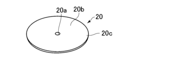
- FIG. 3 is a perspective view of the orifice plate 20.
- the orifice plate 20 is disposed on the body 10, and an orifice 20a that communicates with the first outlet passage 12 is formed therein.
- the orifice plate 20 is a thin disk made of a metal such as stainless steel, and an orifice 20a is formed in the center.
- the orifice plate 20 is disposed on the plate support surface 13a of the accommodating recess 13, and is fixed by being sandwiched between the plate support surface 13a and the pressing surface 30a of the inner member 30.
- the orifice plate 20 is configured to narrow the opening of the second outlet passage 32 of the inner member 30. Although only one orifice 20a is formed in the orifice plate 20, multiple orifices 20a may be formed.
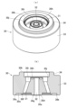
- FIGS. 4(a) and (b) are a perspective view and a cross-sectional view of the inner member 30.
- the inner member 30 is disposed in the accommodation recess 13 and is positioned on the gasket 15 and the orifice plate 20.
- the inner member 30 has four second inlet passages 31 and one second outlet passage 32. Each second inlet passage 31 is connected to the first inlet passage 11 via the through hole 15a.
- the second outlet passage 32 is connected to the first outlet passage 12 via the orifice 20a.
- the inner member 30 is made of a metal such as stainless steel having the same hardness as the body 10, and has a stepped cylindrical shape having a large diameter portion 33 and a small diameter portion 34 located inside the large diameter portion 33 and having an upper end protruding upward on the outer periphery.
- the outer periphery of the large diameter portion 33 fits into the inner periphery of the lower part of the accommodation recess 13 of the body 10 to position the inner member 30 itself with respect to the body 10.
- the second outflow passage 32 penetrates the center of the inner member 30.
- the second outflow passage 32 opens in the center of the underside of the inner member 30, and around it, an annular pressing surface 30a, an annular recess 30b, and an abutment surface 30c are formed in this order in a concentric shape.
- the pressing surface 30a is flat, and an annular pressing protrusion 30d is provided on its outer periphery.
- the second inflow passage 31 opens on the bottom surface 30e of the annular recess 30b, and an annular second protrusion 30f is provided to surround the opening.
- the second protrusion 30f faces the first protrusion 13g in the vertical direction over its entire circumference.
- the annular recess 30b forms a protrusion 30g that protrudes downward at the center of the bottom of the inner member 30.
- the pressing surface 30a and the pressing protrusion 30d are formed on the protrusion 30g.
- the protrusion 30g is inserted into the cylindrical portion 13b.
- the surfaces that make up the pressing surface 30a, the annular recess 30b, and the abutment surface 30c correspond to the lower surface of the inner member 30.
- the contact surface 30c is flat and contacts the contacted surface 13d of the body 10 when the valve element is fixed to the body 10.
- the pressing protrusion 30d is configured to press the upper surface 20b of the orifice plate 20 to seal the connection between the second outlet passage 32 and the first outlet passage 12.
- the second protrusion 30f is configured to bite into the upper surface 15c of the gasket 15 to seal the connection between the second inlet passage 31 and the through hole 15a.
- the pressing protrusion 30d Before pressing the orifice plate 20, the pressing protrusion 30d has an outer edge that is arc-shaped in cross section (see FIG. 7). The pressing protrusion 30d is deformed when pressing the orifice plate 20 and bending the outer peripheral edge 20c (see FIG. 8).
- the second outlet passage 32 opens in the center of the upper surface of the inner member 30, and is surrounded by a circular seat arrangement groove 30h, an annular outlet groove 30i, a diaphragm support portion 30j, and an annular upper end surface 30k, in this order, in a concentric manner.
- the four second inflow passages 31 are formed at equal intervals in the circumferential direction on the circumference.
- the lower end of each second inflow passage 31 opens into the annular recess 30b, and the upper end opens into the annular outlet groove 30i.
- the number of second inflow passages 31 may be one or more.
- Each second inflow passage 31 is inclined inward as it goes upward.
- the lower end of each second inflow passage 31 is connected to the first inflow passage 11 of the body 10 via the through hole 15a of the gasket 15.
- the valve seat 40 is an annular member provided around the opening of the second outlet passage 32 on the upper surface of the inner member 30.
- the valve seat 40 is made of, for example, fluororesin (PTFE).
- PTFE fluororesin
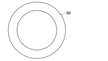
- Figure 6 is a plan view of the thrust ring 60.
- the thrust ring 60 is a generally washer-shaped stainless steel plate coated with a sliding material.
- the thrust ring 60 reduces friction during rotation when the fixing ring 50 is tightened to secure the valve element to the body 10, and prevents the inner member 30 from rotating.
- the thrust ring 60 is not limited to a stainless steel plate coated with a sliding material, and can be any material that can reduce friction during rotation of the fixing ring 50.
- the thrust ring 60 can be made of, for example, a synthetic resin material with excellent sliding properties, or it can be a thrust bearing.
- the diaphragm 70 defines a part of the flow path, and is elastically deformed by being pressed by the diaphragm pressing member 6. When the diaphragm 70 abuts against the valve seat 40, the flow path is closed, and when it is separated from the valve seat 40, the flow path is opened.
- the actuator 3 includes a bonnet 4, an actuator cap 5, a diaphragm retainer 6, a stem 7, a piston 8, and a compression coil spring 9.
- the bonnet 4 is generally cylindrical and has a lower portion 4a, an intermediate portion 4b, and an upper portion 4c.
- the lower portion 4a is inserted into the body 10, and the outer periphery of the upper end portion of the lower portion 4a is screwed into the body 10, thereby fixing the bonnet 4 to the body 10.
- the lower portion 4a penetrates the inner periphery 50b of the fixing ring 50, and its lower end face presses against the pressing adapter 80.
- the intermediate portion 4b is located above the lower portion 4a, and the outer shape of the intermediate portion 4b is a hexagonal column.
- the upper portion 4c is provided to extend upward from the outer edge of the intermediate portion 4b.
- the actuator cap 5 is generally cylindrical with a lid and has an outer tube portion 5a, an upper cover portion 5b, and an inner tube portion 5c.
- the actuator cap 5 is fixed to the bonnet 4 by screwing the lower end of the outer tube portion 5a into the upper portion 4c of the bonnet 4.
- the upper cover portion 5b is provided so as to cover the upper end of the outer tube portion 5a.
- the inner tube portion 5c is connected to the inner end of the upper cover portion 5b.
- the bonnet 4 and the actuator cap 5 form an accommodation space 5d that accommodates the piston 8 and the compression coil spring 9.
- the diaphragm retainer 6 is provided above the diaphragm 70 and is supported by the lower part 4a of the bonnet 4 so that it can move up and down.
- the stem 7 is supported by the middle part 4b of the bonnet 4 so that it can move up and down, and is configured to open and close the flow path by moving toward and away from the diaphragm 70.
- the piston 8 is integral with the stem 7, is provided above the stem 7, and is supported by the bonnet 4 and the actuator cap 5 so that it can move up and down.
- the piston 8 has a base 8a and an upper protrusion 8b.
- the base 8a is generally disk-shaped, and the stem 7 is provided integrally on its lower surface.
- the upper protrusion 8b is generally cylindrical, and extends upward from the upper surface of the base 8a.
- a pressure chamber 8c is defined by the lower surface of the base 8a of the piston 8 and the upper surface of the middle part 4b of the bonnet 4.
- the piston 8 has a driving fluid introduction passage 8d that extends from its upper end to the pressure chamber 8c.
- the compression coil spring 9 is disposed between the lower surface of the upper cover part 5b of the actuator cap 5 and the upper surface of the base 8a of the piston 8, and constantly biases the piston 8 downward.
- Figure 7 is an explanatory diagram of the positional relationship between the pressing protrusion 30d and the clearance groove 13e of the body 10 before pressing the orifice plate 20.
- the outer diameter of the orifice plate 20 is configured to be larger than the outer shape of the plate support surface 13a, and the outer peripheral edge portion 20c of the orifice plate 20 is located on the clearance groove 13e.
- the pressing protrusion 30d has an arc-shaped outer edge in a cross-sectional view.
- the position of the pressing protrusion 30d before deformation provided on the pressing surface 30a is the innermost (center side) position shown in Figure 7 (a), and the position shown in Figure 7 (b) is the outermost (outside) position.
- the pressing protrusion 30d shown in Figure 7 (a) is provided on the pressing surface 30a so that the top P1 is located slightly outside the inner end X of the clearance groove 13e (the outer end of the plate support surface 13a) in the radial direction of the pressing surface 30a.
- the pressing protrusion 30d shown in FIG. 7(b) is provided on the pressing surface 30a so that the inner end P2 of the pressing protrusion 30d is located slightly inside the inner end X of the clearance groove 13e.
- the pressing protrusion 30d is preferably provided between the position shown in FIG. 7(a) (first position) and the position shown in FIG. 7(b) (second position) in the radial direction of the pressing surface 30a.
- the orifice plate 20 is placed on the plate support surface 13a of the accommodating recess 13.
- the gasket 15 is placed in the annular recess 13c of the accommodating recess 13.
- the valve seat 40 is fitted into the seat placement groove 30h of the inner member 30.
- This inner member 30 is placed in the accommodating recess 13 of the body 10.
- the protruding portion 30g of the inner member 30 is inserted into the cylindrical portion 13b.
- Two thrust rings 60 are placed on the annular upper end surface 30k of the inner member 30.
- the male thread portion 50a of the fixing ring 50 is screwed into the female thread portion 13h of the accommodating recess 13, and the fixing ring 50 is tightened until the abutting surface 30c of the inner member 30 abuts against the abutted surface 13d of the body 10, thereby fixing the gasket 15, the orifice plate 20, and the inner member 30 to the body 10.
- the fixing ring 50 When the fixing ring 50 begins to be tightened, the second protrusion 30f of the inner member 30 contacts the upper surface 15c of the gasket 15, and the pressing protrusion 30d of the inner member 30 does not contact the orifice plate 20. After the fixing ring 50 is tightened and the first protrusion 13g and the second protrusion 30f bite into the gasket 15, the pressing protrusion 30d contacts the upper surface 20b of the orifice plate 20 (see Figures 7(a) and (b)). When the fixing ring 50 is tightened further, the outer peripheral edge 20c of the orifice plate 20 is pressed by the pressing protrusion 30d and bent toward the escape groove 13e (see Figures 8(a) and (b)).
- the pressing protrusion 30d is crushed and deformed from the shape shown in Figure 7.
- the fastening of the fixing ring 50 is completed by fastening the fixing ring 50 until the pressing surface 30a of the inner member 30 is in close contact with the upper surface 20b of the orifice plate 20 and the abutting surface 30c of the inner member 30 is in contact with the abutted surface 13d of the body 10.
- FIG. 8(a) the positional relationship between the pressing protrusion 30d and the clearance groove 13e corresponds to FIG. 7(a)
- FIG. 8(b) the positional relationship between the pressing protrusion 30d and the clearance groove 13e corresponds to FIG. 7(b).
- the sealing of the seal portion between the orifice plate 20 and the body 10 and the inner member 30 is completed by tightening the fixing ring 50 until the abutment surface 30c of the inner member 30 is in close contact with the abutted surface 13d of the body 10.
- the tolerances are set so that the seal portion between the orifice plate 20 and the body 10 and the inner member 30 is reliably sealed during the process from when the pressing protrusion 30d comes into contact with the upper surface 20b of the orifice plate 20 until the abutment surface 30c and the abutted surface 13d are in close contact with each other.
- the tolerances in question are the tolerance (build-up tolerance) between the plate support surface 13a and the abutment surface 13d of the body 10, the tolerance (build-up tolerance) of the thickness of the orifice plate 20, and the tolerance (build-up tolerance) between the pressing surface 30a and the abutment surface 30c of the inner member 30.
- a circular escape groove 13e is formed on the outer peripheral edge of the plate support surface 13a, and the outer peripheral edge portion 20c of the orifice plate 20 is pressed by the pressing protrusion portion 30d and bent toward the escape groove 13e. This improves surface contact, improves sealing performance, and suppresses deformation of the orifice plate 20.
- the pressing protrusion 30d is provided between a first position and a second position in the radial direction of the pressing surface 30a.
- the first position is a position where the top P1 of the pressing protrusion 30d is located slightly outside the inner end X of the clearance groove 13e in the radial direction of the pressing surface 30a.
- the second position is a position where the inner end P2 of the pressing protrusion 30d is located slightly inside the inner end X of the clearance groove 13e in the radial direction of the pressing surface 30a. This improves surface contact, thereby improving sealing properties and suppressing deformation of the orifice plate 20.
- the first protrusion 13g bites into the lower surface 15b of the gasket 15, and the second protrusion 30f bites into the upper surface 15c of the gasket 15, forming a seal. This allows the sealing of the sealing portion of the orifice plate 20 and the sealing portion of the gasket 15 to be performed simultaneously.
- the gasket 15 is made of a metal such as annealed stainless steel, but in cases where heat resistance is not required, a resin material such as fluororesin (PCTFE) may be used.
- a thrust ring 60 is used to reduce friction of the fixed ring 50, but if the inner member 30 does not rotate, the thrust ring 60 does not need to be used.
- Valve 10 Body 11: First inlet passage 12: First outlet passage 13: Storage recess 13a: Plate support surface 13b: Cylindrical portion 13c: Annular recess 13d: Contact surface 13e: escape groove, 13g: first protrusion, 13h: female thread portion 15: gasket 15b: lower surface, 15c: upper surface 20: orifice plate 20a: orifice, 20c: outer periphery 30: inner member 30a: pressing surface, 30b: annular recess, 30c: contact surface, 30d: pressing protrusion, 30f: second protrusion, 31: second inflow passage, 32: second outflow passage, 50: fixing ring, P1: top of pressing protrusion, P2: inner end of pressing protrusion, X: inner end of escape groove
Landscapes
- Engineering & Computer Science (AREA)
- General Engineering & Computer Science (AREA)
- Mechanical Engineering (AREA)
- Valve Housings (AREA)
- Check Valves (AREA)
- Pipe Accessories (AREA)
Abstract
オリフィスプレートとそれを挟圧する部材と間のシール部のシール性を確保可能なバルブを提供する。 バルブは、第1流入路と第1流出路とが底面に開口する収容凹部を有するボディと、オリフィスプレートと、第2流入路および第2流出路が形成されたインナー部材と、インナー部材を底面に向かって押圧する固定リングとを備える。収容凹部の底面の中心には第1流出路が開口し、その周囲にそれぞれ環状のプレート支持面および被当接面が形成され、インナー部材の下面の中心には第2流出路が開口し、その周囲にそれぞれ環状の押圧面および当接面が形成され、押圧面には環状の押圧突起部が設けられている。固定リングを収容凹部に対して締め込み当接面が被当接面に密着する過程において、押圧突起部がオリフィスプレートを押圧してオリフィスプレートとボディおよびインナー部材との間のシール部がシールされる。
Description
本開示は、オリフィスを内蔵するバルブに関する。
半導体製造プロセスにおいて、例えば、ALD(Atomic Layer Deposition)およびALE(Atomic Layer Etching)等の微細プロセスでは、処理チャンバに短時間で正確に計量した処理ガスを供給するために、オリフィス内蔵バルブを有する圧力式流量制御装置が用いられる。特許文献1のオリフィス内蔵バルブでは、オリフィスプレートをボディ上に配置し、オリフィスプレート上に座弁体、インナーディスク、ダイヤフラム等を載せて、ボンネットをボディに螺合することにより、弁座体の突条でオリフィスプレートをシール、固定している。
オリフィス内蔵バルブを有する圧力式流量制御装置は、オリフィスのつまり、腐食等による制御流量の異常の有無を自己診断する流量自己診断機能を有するものがある。流量自己診断機能では、装置の初期の圧力降下特性と、診断時の圧力降下特性とを比較して、異常の有無を検知する。従来例のようなオリフィス内蔵バルブにおいて、流量自己診断機能で診断された異常の原因について調査等を行うと、オリフィスプレートのシール部の面接触性が低く、経時的に変形(湾曲)するため、オリフィスプレートのシール部から発生するリーク量の変化が異常の原因であると推察された。このため、オリフィスプレートが変形せず、かつ、オリフィスプレートとそれを保持する挟圧部との間の面接触性及びシール性の確保が求められる。
オリフィスプレートとそれを挟圧する部材との間のシール部が適切な面接触性とシール性を有するようにするため、ボンネットのボディへの締付けトルクを管理することも必要である。この場合に、ボンネットとボディとの螺合部の面の粗さの違いにより、同トルクをかけたとしても締付け角度が異なり、オリフィスプレートに大きな締付け力が加わりオリフィスプレートが変形する可能性、または、オリフィスプレート等の部材に十分な締付け力が加わらずシール性が不十分となる可能性がある。このため、オリフィスプレートにかかる力を均一にする必要がある。
そこで本開示は、オリフィスプレートとそれを挟圧する部材と間のシール部の面接触性とシール性を確保可能なバルブを提供することを目的の一つとする。
上記目的を解決するために、本発明の一態様であるバルブは、第1流入路および第1流出路が形成され、上面に開口して前記第1流入路と前記第1流出路とが底面に開口する収容凹部を有するボディと、前記収容凹部の前記底面の上に配置され、オリフィスが形成されたオリフィスプレートと、前記収容凹部内に配置され、前記第1流入路に連通する第2流入路および前記第1流出路に連通する第2流出路が形成されたインナー部材と、前記インナー部材の上側に位置し、前記収容凹部の内周面に形成されたネジ部に螺合して、前記インナー部材を前記底面に向かって押圧する固定リングと、を備える。前記収容凹部の前記底面の中心には、前記第1流出路が開口し、その周囲にそれぞれ環状のプレート支持面および被当接面がこの順に形成され、前記インナー部材の下面の中心には、第2流出路が開口し、その周囲にそれぞれ環状の押圧面および当接面がこの順に形成され、前記押圧面には環状の押圧突起部が設けられ、前記固定リングを前記収容凹部に対して締め込み前記当接面が前記被当接面に密着する過程において、前記押圧突起部が前記オリフィスプレートを押圧して、前記オリフィスプレートと前記ボディおよび前記インナー部材との間のシール部がシールされるように構成されている。
前記プレート支持面の外周縁には、環状の逃げ溝が形成され、前記オリフィスプレートの外周縁部は、前記押圧突起部に押されて前記逃げ溝側へ屈曲していてもよい。
前記オリフィスプレートを押圧して変形する前の前記押圧突起部は、断面視でその外縁が円弧状をなし、前記押圧面の径方向において第1位置と第2位置との間に設けられ、前記第1位置は、前記変形する前の前記押圧突起部の頂部が、前記径方向において前記逃げ溝の内端よりも僅かに外側に位置する状態の位置であり、前記第2位置は、前記変形する前の前記押圧突起部の内端が、前記径方向において前記逃げ溝の内端よりも僅かに内側に位置する状態の位置であってもよい。
前記収容凹部の前記底面の上に配置され、前記第1流入路および前記第2流入路に連通する貫通孔を有するガスケットをさらに備え、前記収容凹部の前記底面には、前記第1流入路の開口部および前記第1流出路の開口部を包囲するように環状の第1突起部が設けられ、前記インナー部材の下面には、前記第2流入路の開口部および前記第2流出路の開口部を包囲するように環状の第2突起部が設けられ、前記固定リングを前記収容凹部に対して締め込むと、前記第1突起部が前記ガスケットの下面に食い込み、前記第2突起部が前記ガスケットの上面に食い込んで、それぞれシールが形成されるように構成されていてもよい。
本発明によれば、オリフィスプレートとそれを挟圧する部材と間のシール部のシール性を確保可能なバルブを提供することができる。
本開示の一実施形態に係るバルブについて、図面を参照して説明する。
図1は、本実施形態に係る閉状態のバルブ1の断面図である。図2は、図1のバルブ1の要部を拡大した拡大断面図である。本実施形態に係るバルブ1はオリフィス内蔵のダイヤフラムバルブである。
バルブ1は、例えば、ダイヤフラムバルブであり、ボディ部2と、アクチュエータ3とを備える。なお、以下の説明において、バルブ1のアクチュエータ3側を上側、バルブ1のボディ部2側を下側として説明する。
ボディ部2は、ボディ10と、ガスケット15と、オリフィスプレート20と、インナー部材30と、バルブシート40と、固定リング50と、スラストリング60と、ダイヤフラム70と、押えアダプタ80とを備える。
ボディ10は、ステンレス鋼等の金属材料でブロック状に形成されている。ボディ10には、第1流入路11と第1流出路12が形成され、ボディ10の上面に開口する断面円形の孔を有する収容凹部13を備える。なお、ガスケット15、オリフィスプレート20、インナー部材30、バルブシート40、固定リング50、スラストリング60、ダイヤフラム70、および、押えアダプタ80は、本実施形態においてバルブ要素を構成している。
収容凹部13の底面には、中央部に第1流出路12が開口し、その周囲には、それぞれ環状のプレート支持面13a、筒状部13b、環状凹部13c、および、被当接面13dが、この順に同心円状に形成されている。プレート支持面13aは平面状をなし、その外周縁には、環状の逃げ溝13e(図7参照)が形成されている。筒状部13bは、上側へ突出するように設けられている。環状凹部13cの底面13fには、第1流入路11が開口し、環状の第1突起部13gが設けられている。第1突起部13gは当該開口の外側に位置している。被当接面13dは、平面状をなし、インナー部材30の後述の当接面30cが当接する面である。収容凹部13の上側部の内周面には雌ネジ部13hが形成されている。プレート支持面13a、筒状部13b、環状凹部13c、および、被当接面13dを構成する面が、収容凹部13の底面に相当する。
ガスケット15は、軟質の材料で構成された環状の部材であり、本実施形態では焼鈍したステンレス鋼等の金属により構成されている。すなわち、ガスケット15は、ボディ10およびインナー部材30より柔らかい金属により構成されている。ガスケット15は、環状凹部13cに配置され、第1流入路11に連通する貫通孔15aを有する。ガスケット15は、軟質の材料で構成されているので、バルブ要素をボディ10に固定する際、第1突起部13gがガスケット15の下面15bに食い込んで、第1流入路11と貫通孔15aとの接続部をシールするように構成されている。
図3は、オリフィスプレート20の斜視図である。図2、3に示すように、オリフィスプレート20は、ボディ10上に配置され、第1流出路12に連通するオリフィス20aが形成されている。オリフィスプレート20は、ステンレス鋼等の金属製の薄い円盤であり、中心部にオリフィス20aが形成されている。オリフィスプレート20は、収容凹部13のプレート支持面13aに配置され、プレート支持面13aとインナー部材30の押圧面30aとの間に挟持されて固定されている。オリフィスプレート20は、インナー部材30の第2流出路32の開口部を絞るように構成されている。なお、オリフィスプレート20にオリフィス20aを1つのみ形成したが、複数形成してもよい。
図4(a)、(b)は、インナー部材30の斜視図および断面図である。図2、4に示すように、インナー部材30は、収容凹部13内に配置され、ガスケット15およびオリフィスプレート20上に位置している。インナー部材30には、4本の第2流入路31および1本の第2流出路32が形成されている。各第2流入路31は、貫通孔15aを介して第1流入路11に連通している。第2流出路32は、オリフィス20aを介して第1流出路12に連通している。インナー部材30は、ボディ10と同じ硬度を有するステンレス鋼等の金属により構成され、外周側に、大径部33と大径部33の内側に位置し上端が上側に突出する小径部34とを有する略段付円筒状をなしている。大径部33の外周面は、ボディ10の収容凹部13の下側部の内周面に嵌合して、インナー部材30自体をボディ10に対して位置決めする。
第2流出路32は、インナー部材30の中央部を貫通している。インナー部材30の下面には、中央部に第2流出路32が開口し、その周囲には、それぞれ環状の押圧面30a、環状凹部30b、および当接面30cがこの順に同心円状に形成されている。押圧面30aは、平面状をなし、その外周側には、環状の押圧突起部30dが設けられている。環状凹部30bの底面30eには、第2流入路31が開口し、開口部を包囲するように環状の第2突起部30fが設けられている。第2突起部30fは、その全周に渡って、上下方向において第1突起部13gに対向している。環状凹部30bにより、インナー部材30の底部の中央部は、下側へ突出する突出部30gを構成している。突出部30gに押圧面30aおよび押圧突起部30dが形成されている。バルブ要素をボディ10に固定する際、突出部30gは筒状部13bに挿入される。押圧面30a、環状凹部30b、および当接面30cを構成する面が、インナー部材30の下面に相当する。
当接面30cは、平面状をなし、バルブ要素をボディ10に固定する際、ボディ10の被当接面13dに当接する。押圧突起部30dがオリフィスプレート20の上面20bを押圧して、第2流出路32と第1流出路12との接続部をシールするように構成されている。第2突起部30fがガスケット15の上面15cに食い込んで、第2流入路31と貫通孔15aとの接続部をシールするように構成されている。押圧突起部30dは、オリフィスプレート20を押圧する前は、断面視でその外縁が円弧状をなしている(図7参照)。押圧突起部30dは、オリフィスプレート20を押圧しその外周縁部20cを屈曲させるときに変形する(図8参照)。
インナー部材30の上面側には、中央部に第2流出路32が開口し、その周囲には、それぞれ円環状のシート配置溝30h、環状流出溝30i、ダイヤフラム支持部30j、および環状上端面30kがこの順に同心円状に形成されている。4本の第2流入路31は、円周上の周方向に等間隔に形成されている。各第2流入路31は、下端が環状凹部30bに開口し、上端が環状流出溝30iに開口している。第2流入路31の本数は、1本以上であればよい。各第2流入路31は、上方に向かうにつれて内側に傾斜している。各第2流入路31の下端は、ガスケット15の貫通孔15aを介して、ボディ10の第1流入路11に連通している。
バルブシート40は、インナー部材30の上面の第2流出路32の開口部周囲に設けられた円環状の部材である。バルブシート40は、例えば、フッ素樹脂(PTFE)製である。バルブシート40は、インナー部材30のシート配置溝30hに嵌め込まれている。
図5(a)、(b)は、固定リング50の斜視図および断面図である。図2、5に示すように、固定リング50は、ステンレス鋼等の金属により構成され、略円環状をなしている。固定リング50の外周面には雄ねじ部50aが形成され、内周面50bには回転工具と係合するダブルヘックス構造が形成されている。固定リング50の下面側には、プレート収容凹部50cが形成されている。プレート収容凹部50cには、2枚のスラストリング60が収容される。
図6は、スラストリング60の平面図である。スラストリング60は、略ワッシャ状をなすステンレス鋼板に摺動材をコーティングした部材である。スラストリング60により、バルブ要素をボディ10に固定する際、固定リング50で締め付けるための回転時の摩擦を低減し、インナー部材30の供回りを防止している。スラストリング60は、ステンレス鋼板に摺動材をコーティングした部材に限られず、固定リング50の回転時の摩擦を低減できるものであればなんでもよい。スラストリング60は、例えば、摺動性に優れた合成樹脂材料により構成されていてもよいし、スラストベアリングであってもよい。
図2に示すように、ダイヤフラム70は、インナー部材30の上に配置され、バルブシート40から離間またはバルブシート40に当接して、第2流入路31と第2流出路32との間を連通または遮断する部材である。ダイヤフラム70は、特殊ステンレス鋼等の金属製薄板およびニッケル・コバルト合金薄板を積層したものの中央部を上方へ膨出させることにより形成されている。ダイヤフラム70は、インナー部材30のダイヤフラム支持部30jにより支持され、リング状の押えアダプタ80を介して、アクチュエータ3のボンネット4の下側部4aによって押圧されることにより固定される。ダイヤフラム70は、流路の一部を画定しており、ダイヤフラム押え6により押圧されて弾性変形し、バルブシート40に当接すると流路が閉鎖され、バルブシート40から離間すると流路が開放される。
図1に示すように、アクチュエータ3は、ボンネット4と、アクチュエータキャップ5と、ダイヤフラム押え6と、ステム7と、ピストン8と、圧縮コイルばね9とを備える。
ボンネット4は、略円筒状をなし、下側部4aと、中間部4bと、上側部4cとを有する。下側部4aは、ボディ10に挿入され、下側部4aの上端部の外周部をボディ10に対し螺合させることにより、ボンネット4がボディ10に対し固定されている。下側部4aは、固定リング50の内周面50b内を貫通し、その下端面は押えアダプタ80を押圧している。中間部4bは、下側部4aの上側に位置し、中間部4bの外形は6角柱状をなしている。上側部4cは、中間部4bの外縁部から上方に延びるように設けられている。
アクチュエータキャップ5は、略有蓋円筒状をなし、外筒部5aと、上蓋部5bと、内筒部5cとを有する。外筒部5aの下端部をボンネット4の上側部4cに螺合させることにより、アクチュエータキャップ5がボンネット4に固定されている。上蓋部5bは、外筒部5aの上端を覆うように設けられている。内筒部5cは、上蓋部5bの内端部に接続されている。ボンネット4とアクチュエータキャップ5とにより、ピストン8および圧縮コイルばね9を収容する収容空間5dが形成されている。
ダイヤフラム押え6は、ダイヤフラム70の上側に設けられ、ボンネット4の下側部4aにより上下方向に移動可能に支持されている。ステム7は、ボンネット4の中間部4bにより上下方向に移動可能に支持され、ダイヤフラム70に対して近接および離間移動することにより、流路を開閉させるように構成されている。
ピストン8は、ステム7と一体的に構成され、ステム7の上側に設けられ、ボンネット4およびアクチュエータキャップ5により上下方向に移動可能に支持されている。ピストン8は、基部8aと、上突出部8bとを有する。基部8aは、略円盤状をなし、その下面にステム7が一体的に設けられている。上突出部8bは、略円筒状をなし、基部8aの上面から上側に向かって延びている。ピストン8の基部8aの下面とボンネット4の中間部4bの上面とにより圧力室8cが画成されている。ピストン8には、その上端から圧力室8cまで延びる駆動流体導入路8dが形成されている。圧縮コイルばね9は、アクチュエータキャップ5の上蓋部5bの下面とピストン8の基部8aの上面との間に配置されており、ピストン8を常に下側に付勢している。
バルブ1へ駆動流体が供給されると、駆動流体は、駆動流体導入路8dを通過して、圧力室8cに流入する。圧力室8cに駆動流体が流入すると、ピストン8が、圧縮コイルばね9の付勢力に抗して上昇する。これにより、ステム7が先端に設けられたピストン8が上死点に移動し、ダイヤフラム70の弾性力および流体(ガス)の圧力によりダイヤフラム押え6が上側に移動し、第2流入路31と第2流出路32とが連通し、バルブ1は開状態となる。
次に、オリフィスプレート20を押圧して変形する前の押圧突起部30dとボディ10の逃げ溝13eとの位置関係について図7を参照して説明する。
図7は、オリフィスプレート20を押圧する前の押圧突起部30dとボディ10の逃げ溝13eとの位置関係の説明図である。オリフィスプレート20の外径は、プレート支持面13aの外形よりも大きく構成され、オリフィスプレート20の外周縁部20cは、逃げ溝13e上に位置する。押圧突起部30dは、断面視でその外縁が円弧状をなしている。例えば、押圧面30aに設けられる変形前の押圧突起部30dの位置は、図7(a)に示す位置が最も内側(中心側)の位置であり、図7(b)に示す位置が最も外側(外側)の位置である。図7(a)に示す押圧突起部30dは、押圧面30aの径方向において、頂部P1が逃げ溝13eの内端X(プレート支持面13aの外端)よりも僅かに外側に位置するように押圧面30aに設けられている。図7(b)に示す押圧突起部30dは、押圧突起部30dの内端P2が逃げ溝13eの内端Xよりも僅かに内側に位置するように押圧面30aに設けられている。本実施形態において、押圧突起部30dは、押圧面30aの径方向において、図7(a)に示す位置(第1位置)と図7(b)に示す位置(第2位置)との間に設けられていることが好ましい。
次に、バルブ1の組立手順について図1、2を参照して説明する。
オリフィスプレート20が収容凹部13のプレート支持面13aに配置される。ガスケット15が収容凹部13の環状凹部13cに配置される。バルブシート40が、インナー部材30のシート配置溝30hに嵌め込まれる。このインナー部材30は、ボディ10の収容凹部13に載置される。この時、インナー部材30の突出部30gが、筒状部13bに挿入される。2枚のスラストリング60が、インナー部材30の環状上端面30k上に配置される。固定リング50の雄ねじ部50aが収容凹部13の雌ネジ部13hに螺合され、インナー部材30の当接面30cがボディ10の被当接面13dに当接するまで固定リング50を締め込むことにより、ガスケット15、オリフィスプレート20、およびインナー部材30がボディ10に固定される。
ダイヤフラム70がインナー部材30のダイヤフラム支持部30jに配置され、押えアダプタ80がダイヤフラム70上に配置され、アクチュエータ3のボンネット4が収容凹部13の雌ネジ部13hにねじ込まれる。これにより、本実施形態のバルブ1が組み立てられる。
固定リング50の締め込みを始めた時点で、インナー部材30の第2突起部30fは、ガスケット15の上面15cに接触し、インナー部材30の押圧突起部30dは、オリフィスプレート20に接触していない。固定リング50を締め込み、第1突起部13gおよび第2突起部30fがガスケット15に食い込んだ後に、押圧突起部30dは、オリフィスプレート20の上面20bに接触する(図7(a)、(b)参照)。固定リング50をさらに締め込むと、オリフィスプレート20の外周縁部20cが押圧突起部30dに押されて逃げ溝13e側へ屈曲する(図8(a)、(b)参照)。この時、押圧突起部30dは、押しつぶされて図7に示した形状から変形する。インナー部材30の押圧面30aが、オリフィスプレート20の上面20bに密着し、インナー部材30の当接面30cがボディ10の被当接面13dに当接するまで固定リング50を締め込むことにより、固定リング50の締め付けが完了する。図8(a)は、押圧突起部30dと逃げ溝13eとの位置関係が図7(a)に対応し、図8(b)は、押圧突起部30dと逃げ溝13eとの位置関係が図7(b)に対応する。
このように、本実施形態のバルブ1では、インナー部材30の当接面30cがボディ10の被当接面13dに密着するまで固定リング50を締め付けることで、オリフィスプレート20と、ボディ10およびインナー部材30との間のシール部のシールが完了するように構成されている。これにより、トルク管理等しなくても、オリフィスプレート20とそれを挟圧する部材との間のシール部のシール性を容易に確保することができる。このため、異なるバルブ1間でのシール部のシール性を容易に均一にすることができる。本実施形態では、押圧突起部30dがオリフィスプレート20の上面20bに接触してから当接面30cと被当接面13dとが密着するまでの過程において、オリフィスプレート20とボディ10およびインナー部材30との間のシール部が確実にシールされるように公差の設定がなされている。当該公差とは、ボディ10のプレート支持面13aと被当接面13dとの公差(積み上げ公差)、オリフィスプレート20の厚さの公差(積み上げ公差)、および、インナー部材30の押圧面30aと当接面30cとの公差(積み上げ公差)である。
プレート支持面13aの外周縁には、環状の逃げ溝13eが形成され、オリフィスプレート20の外周縁部20cは、押圧突起部30dに押されて逃げ溝13e側へ屈曲している。これにより、面接触性が向上するため、シール性も向上し、オリフィスプレート20の変形を抑制することができる。
押圧突起部30dは、押圧面30aの径方向において第1位置と第2位置との間に設けられている。第1位置は、押圧面30aの径方向において、押圧突起部30dの頂部P1が逃げ溝13eの内端Xよりも僅かに外側に位置する位置である。第2位置は、押圧面30aの径方向において、押圧突起部30dの内端P2が逃げ溝13eの内端Xよりも僅かに内側に位置する位置である。これにより、面接触性が向上するため、シール性も向上し、オリフィスプレート20の変形を抑制することができる。
固定リング50を収容凹部13に対して締め込むと、第1突起部13gがガスケット15の下面15bに食い込み、第2突起部30fがガスケット15の上面15cに食い込んで、それぞれシールが形成されるように構成されている。これにより、オリフィスプレート20のシール部のシールと、ガスケット15のシール部のシールとを同時に行うことができる。
本開示は、上述した実施例に限定されない。当業者であれば、本開示の範囲内で、種々の追加や変更等を行うことができる。
例えば、ガスケット15を焼鈍したステンレス鋼等の金属で構成したが、耐熱性がそれほど要求されない場合等では、例えば、フッ素樹脂(PCTFE)等の樹脂材料であってもよい。固定リング50の摩擦低減のためにスラストリング60を用いたが、インナー部材30の供回りが発生しなければスラストリング60を用いなくてもよい。
1:バルブ
10:ボディ
11:第1流入路
12:第1流出路
13:収容凹部
13a:プレート支持面、13b:筒状部、13c:環状凹部、13d:被当接面、
13e:逃げ溝、13g:第1突起部、13h:雌ネジ部
15:ガスケット
15b:下面、15c:上面
20:オリフィスプレート
20a:オリフィス、20c:外周縁部
30:インナー部材
30a:押圧面、30b:環状凹部、30c:当接面、30d:押圧突起部、
30f:第2突起部、31:第2流入路、32:第2流出路
50:固定リング
P1:押圧突起部の頂部
P2:押圧突起部の内端
X:逃げ溝の内端
10:ボディ
11:第1流入路
12:第1流出路
13:収容凹部
13a:プレート支持面、13b:筒状部、13c:環状凹部、13d:被当接面、
13e:逃げ溝、13g:第1突起部、13h:雌ネジ部
15:ガスケット
15b:下面、15c:上面
20:オリフィスプレート
20a:オリフィス、20c:外周縁部
30:インナー部材
30a:押圧面、30b:環状凹部、30c:当接面、30d:押圧突起部、
30f:第2突起部、31:第2流入路、32:第2流出路
50:固定リング
P1:押圧突起部の頂部
P2:押圧突起部の内端
X:逃げ溝の内端
Claims (4)
- 第1流入路および第1流出路が形成され、上面に開口して前記第1流入路と前記第1流出路とが底面に開口する収容凹部を有するボディと、
前記収容凹部の前記底面の上に配置され、オリフィスが形成されたオリフィスプレートと、
前記収容凹部内に配置され、前記第1流入路に連通する第2流入路および前記第1流出路に連通する第2流出路が形成されたインナー部材と、
前記インナー部材の上側に位置し、前記収容凹部の内周面に形成されたネジ部に螺合して、前記インナー部材を前記底面に向かって押圧する固定リングと、を備え、
前記収容凹部の前記底面の中心には、前記第1流出路が開口し、その周囲にそれぞれ環状のプレート支持面および被当接面がこの順に形成され、
前記インナー部材の下面の中心には、第2流出路が開口し、その周囲にそれぞれ環状の押圧面および当接面がこの順に形成され、前記押圧面には環状の押圧突起部が設けられ、
前記固定リングを前記収容凹部に対して締め込み前記当接面が前記被当接面に密着する過程において、前記押圧突起部が前記オリフィスプレートを押圧して、前記オリフィスプレートと前記ボディおよび前記インナー部材との間のシール部がシールされるように構成された、バルブ。 - 前記プレート支持面の外周縁には、環状の逃げ溝が形成され、
前記オリフィスプレートの外周縁部は、前記押圧突起部に押されて前記逃げ溝側へ屈曲している、請求項1に記載のバルブ。 - 前記オリフィスプレートを押圧して変形する前の前記押圧突起部は、断面視でその外縁が円弧状をなし、前記押圧面の径方向において第1位置と第2位置との間に設けられ、
前記第1位置は、前記変形する前の前記押圧突起部の頂部が、前記径方向において前記逃げ溝の内端よりも僅かに外側に位置する状態の位置であり、前記第2位置は、前記変形する前の前記押圧突起部の内端が、前記径方向において前記逃げ溝の内端よりも僅かに内側に位置する状態の位置である、請求項2に記載のバルブ。 - 前記収容凹部の前記底面の上に配置され、前記第1流入路および前記第2流入路に連通する貫通孔を有するガスケットをさらに備え、
前記収容凹部の前記底面には、前記第1流入路の開口部および前記第1流出路の開口部を包囲するように環状の第1突起部が設けられ、
前記インナー部材の下面には、前記第2流入路の開口部および前記第2流出路の開口部を包囲するように環状の第2突起部が設けられ、
前記固定リングを前記収容凹部に対して締め込むと、前記第1突起部が前記ガスケットの下面に食い込み、前記第2突起部が前記ガスケットの上面に食い込んで、それぞれシールが形成されるように構成されている、請求項1に記載のバルブ。
Applications Claiming Priority (2)
| Application Number | Priority Date | Filing Date | Title |
|---|---|---|---|
| JP2023-220853 | 2023-12-27 | ||
| JP2023220853 | 2023-12-27 |
Publications (1)
| Publication Number | Publication Date |
|---|---|
| WO2025142244A1 true WO2025142244A1 (ja) | 2025-07-03 |
Family
ID=96217481
Family Applications (1)
| Application Number | Title | Priority Date | Filing Date |
|---|---|---|---|
| PCT/JP2024/041577 Pending WO2025142244A1 (ja) | 2023-12-27 | 2024-11-25 | バルブ |
Country Status (1)
| Country | Link |
|---|---|
| WO (1) | WO2025142244A1 (ja) |
Citations (3)
| Publication number | Priority date | Publication date | Assignee | Title |
|---|---|---|---|---|
| JPH07139649A (ja) * | 1993-11-15 | 1995-05-30 | Motoyama Seisakusho:Kk | ダイヤフラム弁構造 |
| WO2001094824A1 (en) * | 2000-06-05 | 2001-12-13 | Fujikin Incorporated | Orifice-built-in valve |
| WO2020158512A1 (ja) * | 2019-01-31 | 2020-08-06 | 株式会社フジキン | 流路アセンブリ、この流路アセンブリを用いたバルブ装置、流体制御装置、半導体製造装置および半導体製造方法 |
-
2024
- 2024-11-25 WO PCT/JP2024/041577 patent/WO2025142244A1/ja active Pending
Patent Citations (3)
| Publication number | Priority date | Publication date | Assignee | Title |
|---|---|---|---|---|
| JPH07139649A (ja) * | 1993-11-15 | 1995-05-30 | Motoyama Seisakusho:Kk | ダイヤフラム弁構造 |
| WO2001094824A1 (en) * | 2000-06-05 | 2001-12-13 | Fujikin Incorporated | Orifice-built-in valve |
| WO2020158512A1 (ja) * | 2019-01-31 | 2020-08-06 | 株式会社フジキン | 流路アセンブリ、この流路アセンブリを用いたバルブ装置、流体制御装置、半導体製造装置および半導体製造方法 |
Also Published As
| Publication number | Publication date |
|---|---|
| TW202526204A (zh) | 2025-07-01 |
Similar Documents
| Publication | Publication Date | Title |
|---|---|---|
| US5669596A (en) | Diaphragm valve | |
| JP6335926B2 (ja) | 溶接されたダイヤフラム弁座担体を有するダイヤフラム弁 | |
| US5295662A (en) | Fluid flow-controller with improved diaphragm | |
| KR0153229B1 (ko) | 다이어프램 밸브 | |
| EP0892204B1 (en) | Improved diaphragm valve with leak detection | |
| JP2604279Y2 (ja) | ダイアフラム弁 | |
| CN102803800B (zh) | 用于流体压力装置的阀结构 | |
| US11306830B2 (en) | Valve device | |
| CN100380031C (zh) | 流体控制器 | |
| JPH08219304A (ja) | ダイヤフラム弁 | |
| JP7653780B2 (ja) | ダイヤフラムの製造方法、バルブ用ダイヤフラム及びこれを備えるダイヤフラムバルブ | |
| WO2025142244A1 (ja) | バルブ | |
| JP2005321061A (ja) | 高温用弁 | |
| TWI920822B (zh) | 閥 | |
| TWI828342B (zh) | 內部設有孔口之閥及流量控制裝置 | |
| WO2025154454A1 (ja) | バルブおよびバルブの組立方法 | |
| TWI807271B (zh) | 閥裝置 | |
| JP7025915B2 (ja) | ダイヤフラムバルブ | |
| US2952274A (en) | Multiport valve | |
| JP7348628B2 (ja) | アクチュエータ及びそれを備えたエアオペレートバルブ | |
| JPS6367481A (ja) | ダイヤフラム弁 | |
| JP7401896B2 (ja) | バルブ | |
| JP7480981B2 (ja) | バルブ装置 | |
| JP2025048349A (ja) | オリフィス内蔵バルブおよび流量制御装置 | |
| JP5764315B2 (ja) | ダイヤフラム弁 |
Legal Events
| Date | Code | Title | Description |
|---|---|---|---|
| 121 | Ep: the epo has been informed by wipo that ep was designated in this application |
Ref document number: 24912136 Country of ref document: EP Kind code of ref document: A1 |