WO2025142149A1 - 電動トラクタ - Google Patents
電動トラクタ Download PDFInfo
- Publication number
- WO2025142149A1 WO2025142149A1 PCT/JP2024/039808 JP2024039808W WO2025142149A1 WO 2025142149 A1 WO2025142149 A1 WO 2025142149A1 JP 2024039808 W JP2024039808 W JP 2024039808W WO 2025142149 A1 WO2025142149 A1 WO 2025142149A1
- Authority
- WO
- WIPO (PCT)
- Prior art keywords
- electric motor
- power
- electric
- battery
- frame
- Prior art date
- Legal status (The legal status is an assumption and is not a legal conclusion. Google has not performed a legal analysis and makes no representation as to the accuracy of the status listed.)
- Pending
Links
Images




Classifications
-
- B—PERFORMING OPERATIONS; TRANSPORTING
- B60—VEHICLES IN GENERAL
- B60K—ARRANGEMENT OR MOUNTING OF PROPULSION UNITS OR OF TRANSMISSIONS IN VEHICLES; ARRANGEMENT OR MOUNTING OF PLURAL DIVERSE PRIME-MOVERS IN VEHICLES; AUXILIARY DRIVES FOR VEHICLES; INSTRUMENTATION OR DASHBOARDS FOR VEHICLES; ARRANGEMENTS IN CONNECTION WITH COOLING, AIR INTAKE, GAS EXHAUST OR FUEL SUPPLY OF PROPULSION UNITS IN VEHICLES
- B60K1/00—Arrangement or mounting of electrical propulsion units
- B60K1/02—Arrangement or mounting of electrical propulsion units comprising more than one electric motor
-
- B—PERFORMING OPERATIONS; TRANSPORTING
- B60—VEHICLES IN GENERAL
- B60K—ARRANGEMENT OR MOUNTING OF PROPULSION UNITS OR OF TRANSMISSIONS IN VEHICLES; ARRANGEMENT OR MOUNTING OF PLURAL DIVERSE PRIME-MOVERS IN VEHICLES; AUXILIARY DRIVES FOR VEHICLES; INSTRUMENTATION OR DASHBOARDS FOR VEHICLES; ARRANGEMENTS IN CONNECTION WITH COOLING, AIR INTAKE, GAS EXHAUST OR FUEL SUPPLY OF PROPULSION UNITS IN VEHICLES
- B60K1/00—Arrangement or mounting of electrical propulsion units
- B60K1/04—Arrangement or mounting of electrical propulsion units of the electric storage means for propulsion
-
- E—FIXED CONSTRUCTIONS
- E02—HYDRAULIC ENGINEERING; FOUNDATIONS; SOIL SHIFTING
- E02F—DREDGING; SOIL-SHIFTING
- E02F9/00—Component parts of dredgers or soil-shifting machines, not restricted to one of the kinds covered by groups E02F3/00 - E02F7/00
- E02F9/02—Travelling-gear, e.g. associated with slewing gears
-
- F—MECHANICAL ENGINEERING; LIGHTING; HEATING; WEAPONS; BLASTING
- F16—ENGINEERING ELEMENTS AND UNITS; GENERAL MEASURES FOR PRODUCING AND MAINTAINING EFFECTIVE FUNCTIONING OF MACHINES OR INSTALLATIONS; THERMAL INSULATION IN GENERAL
- F16H—GEARING
- F16H57/00—General details of gearing
- F16H57/02—Gearboxes; Mounting gearing therein
Definitions
- the electric tractor disclosed in Japanese Patent Application Laid-Open No. 2014-143965 is equipped with a battery, a first electric motor for driving (referred to in the document as “driving system electric motor (7)"), and a second electric motor for at least one of working and hydraulic drive (referred to in the document as “electric motor (6)").
- JP 2014-143965 A In a configuration where two electric motors are provided, one for driving and one for working, securing space for the electric motors and reducing procurement costs tend to be issues.
- the two electric motors disclosed in JP 2014-143965 A are of different types. This tends to increase motor procurement costs and make the layout of the electric motors complicated.
- the object of the present invention is to provide an electric tractor that has a simple and inexpensive configuration and can accommodate two electric motors in a compact arrangement.
- the electric tractor of the present invention is equipped with a battery that stores electric power, a first electric motor for driving that receives electric power from the battery, and a second electric motor for at least one of working and hydraulic driving that receives electric power from the battery, and is characterized in that the size of the first electric motor and the size of the second electric motor are the same or approximately the same.
- the first electric motor and the second electric motor are the same size, it is necessary to prepare only one type of electric motor, which reduces procurement and management costs.
- the layout of the two electric motors is likely to be a simple configuration.
- the risk of workers mistakenly installing different types of electric motors during the assembly process is avoided. This realizes an electric tractor that can compactly arrange two electric motors with a simple and inexpensive configuration.
- the capacity of the first electric motor and the capacity of the second electric motor are the same or approximately the same.
- the first electric motor and the second electric motor have the same capacity, it is only necessary to prepare one type of electric motor, which further reduces procurement costs and management costs. In addition, the risk of workers mistakenly installing different types of electric motors during the assembly process is avoided.
- a power transmission device that transmits at least one of the power for traveling and the power for working, and it is preferable that the power transmission device is disposed behind the first electric motor and the second electric motor.
- the power transmission device preferably has a power transmission mechanism that transmits the power and a housing case that houses the power transmission mechanism, and the first electric motor and the second electric motor are cantilever-supported at the front of the housing case.
- housing cases for power transmission devices in tractors have traditionally often been used as frame structures. For this reason, with this configuration, it is possible to configure the housing case to function both as a frame structure and as a support for the two electric motors.
- a traveling device driven by the traveling power and a work output unit that supplies the work power to a work device are provided, and that the power transmission device is provided with a first power transmission mechanism that transmits the power from the first electric motor to the traveling device and a second power transmission mechanism that transmits the power from the second electric motor to the work output unit.
- the power transmission system for driving and the power transmission system for working are completely independent.
- each of the first electric motor and the second electric motor only needs to be driven with the power required.
- the first electric motor and the second electric motor are arranged so that their output shafts are at the same or approximately the same height in the vertical direction.
- This configuration makes it easy to simplify the layout of the two electric motors.
- the first electric motor and the second electric motor are arranged side by side to the left and right of each other.
- the driver's section 3, in which the operator sits, is located above the accommodation frame A and the transmission case 15.
- the ROPS frame 31 is attached to the transmission case 15, extends upward, and is located at the rear of the driver's section 3.
- the battery 4 that supplies power to the electric motors M1, M2 is attached to the first front frame 2, and a bonnet 12 is provided to cover the battery 4.
- the front frame 6 and front wall portion 15F are configured as flat plates extending in the up-down and left-right directions.
- the front frame 6 and front wall portion 15F extend across the lateral direction of the fuselage 1, from the right to the left of the fuselage 1.
- the right and left side frames 5 are configured as flat plates extending in the up-down and front-to-rear directions, and are slightly curved (see Figure 8).
- the front portion of the side frame 5 is connected to the right and left portions of the rear surface of the front frame 6, and the rear portion of the side frame 5 is connected to the right and left portions of the front surface of the front wall portion 15F.
- the upper frame 19 extends in the left-right direction across the upper portions of the right and left horizontal frames 5.
- the upper frame 19 is connected to each of the upper portions of the right and left horizontal frames 5.
- the rotation axis X1 of the electric motor M1 and the rotation axis X2 of the electric motor M2 are located at the same position in the vertical direction and extend parallel to each other in the same direction.
- the output shaft of the electric motor M1 and the output shaft of the electric motor M2 extend parallel to each other in the same direction.
- the front wheel transmission shaft 17 extends along each of the rotation axis X1 and the rotation axis X2. That is, the electric motor M1 and the electric motor M2 are arranged so that their output shafts are at the same (including approximately the same) height in the vertical direction.
- the electric motor M1 and the electric motor M2 are arranged so that their output shafts extend parallel to each other (including approximately the same) in the same direction (including approximately the same).
- the front wheel transmission shaft 17 corresponds to the "transmission shaft".
- the rotation axis X1 of the electric motor M1 and the rotation axis X2 of the electric motor M2 are each located at a position that overlaps with the lower edge of the front and rear frame portions 2F of the first front frame 2 in the vertical direction.
- the electric motors M1 and M2 are arranged so that the rotation axis X1 and X2 are located at the same position (including approximately the same position) as the lower edge of the front and rear frame portions 2F in the vertical direction.
- the left-right width of electric motor M1 is the same as the left-right width of electric motor M2.
- the radial width of electric motor M1 and the radial width of electric motor M2 are the same (including approximately the same).
- the front-rear width of electric motor M1 and the front-rear width of electric motor M2 are the same.
- the width of electric motor M1 in the direction of rotation axis X1 and the width of electric motor M2 in the direction of rotation axis X2 are the same (including approximately the same).
- the size of electric motor M1 and the size of electric motor M2 are the same (including approximately the same).
- the capacity of electric motor M1 and the capacity of electric motor M1 are the same (including approximately the same). This makes it easier to reduce the production costs and procurement costs of electric motors M1 and M2.
- the cases of electric motor M1 and electric motor M2 are each formed into a cylindrical shape. Electric motor M1 and electric motor M2 are arranged with a gap between them so that there is a space between the cases of electric motor M1 and electric motor M2. A front wheel transmission shaft 17 that transmits driving power to the front wheels 10 passes through this space (see Figures 4 and 8).
- the power transmission device T is for transmitting driving power to the front wheels 10.
- a front wheel transmission shaft 17 extends forward from the power transmission device T.
- the front frame 6, first front frame 2, front axle case 10A, and left and right front wheels 10 are located in front of the electric motor M1 and electric motor M2.
- the front wheel transmission shaft 17 extends from the power transmission device T (transmission case 15) through the space between the electric motor M1 and electric motor M2, the space in the recess 6a, and the space below the first front frame 2 to the front axle case 10A.
- the front wheel transmission shaft 17 receives driving power from the power transmission device T and transmits it to the front axle case 10A.
- the front wheel transmission shaft 17 extends in the fore-and-aft direction between the power transmission device T (transmission case 15) and the front axle case 10A of the front wheels 10.
- the electric motor M1 and the power transmission device T (transmission case 15) are disposed behind the first front frame 2, and the front wheel transmission shaft 17 extends between the power transmission device T (transmission case 15) and the front axle case 10A.
- the front wheel transmission shaft 17 extends from the side where the electric motors M1, M2 are located to the front axle case 10A, and transmits driving power to the front wheels 10.
- the electric motor M1 and the electric motor M2 are disposed between the front wheels 10 and the power transmission device T.
- the front wheel transmission shaft 17 passes between the electric motor M1 and the electric motor M2.
- the battery 4 supplies power to two inverters 14A and 14B.
- Each of the inverters 14A and 14B receives DC current from the battery 4 and converts it into three-phase AC current.
- the DC power of the battery 4 is converted to AC power in the left inverter 14A and supplied to the electric motor M1. This causes the electric motor M1 to operate.
- the DC power of the battery 4 is converted to AC power in the right inverter 14B and supplied to the electric motor M2, which then operates the electric motor M2.
- Inverter 14A is disposed on the side opposite electric motor M1 across lateral frame 5 on the left side of the machine body.
- Inverter 14B is disposed on the side opposite electric motor M2 across lateral frame 5 on the right side of the machine body.
- inverters 14A, 14B for electric motor M1 and electric motor M2 are disposed on the left and right outer sides of electric motor M1 and electric motor M2.
- Inverters 14A, 14B are disposed so that their respective upper portions are positioned below floor 35 in the vertical direction.
- each of the inverters 14A and 14B is disposed behind the loader mounting portion 8.
- the loader mounting portion 8 and the inverters 14A and 14B are adjacent to each other in the front-rear direction. That is, the inverter 14A is adjacent to the electric motor M1 in the left-right direction, and is adjacent to the loader mounting portion 8 on the left side of the machine body in the front-rear direction. Furthermore, the inverter 14B is adjacent to the electric motor M2 in the left-right direction, and is adjacent to the loader mounting portion 8 on the right side of the machine body in the front-rear direction.
- Inverter 14A is located on the inside side of the aircraft relative to step 34. In other words, inverters 14A and 14B overlap with step 34 in a side view of the aircraft.
- the upper mounting portion 5a is provided on the upper part of the front portion of the horizontal frame 5, facing diagonally upward, and the lower mounting portion 5a is provided on the lower part of the front portion of the horizontal frame 5, facing diagonally downward.
- the right loader mounting portion 8 is connected to the mounting portion 5a of the right lateral frame 5, and the left loader mounting portion 8 is connected to the mounting portion 5a of the left lateral frame 5. As described below, a work device such as a front loader F (see FIG. 3) is attached to the right and left loader mounting portions 8. Each of the left and right loader mounting portions 8 supports a work device such as a front loader F so that it can be attached and detached.
- a loader mounting portion 8 is supported on the front of each of the left and right lateral frames 5.
- Each of the left and right loader mounting portions 8 is located laterally outboard of the aircraft body relative to the lateral frames 5.
- the front end portion of each of the left and right loader mounting portions 8 is located forward of the lateral frames 5.
- Each of the left and right loader mounting portions 8 is adjacent to the outer lateral end portion of the front frame 6.
- the loader mounting part 8 on the left side of the machine body is adjacent to the front side of the step 34. In the front-rear direction, the loader mounting part 8 is disposed between the front wheel 10 and the step 34. In addition, the loader mounting part 8 is disposed between the battery 4 and the electric motors M1, M2 in the front-rear direction. The loader mounting part 8 is disposed laterally outboard of the battery 4 in the left-right direction.
- the base end of the front loader F is connected to the loader mounting part 8 as shown in FIG. 3.
- the front end of the reinforcing beam 9 is connected to the base end of the front loader F.
- the base end of the front loader F is sandwiched between the loader mounting part 8 and the front end of the reinforcing beam 9 in the left-right direction.
- the left and right reinforcing beams 9 extend forward and backward, and the rear ends of the left and right reinforcing beams 9 are supported by the axle cases of the rear wheels 11 in the transmission case 15.
- the left and right reinforcing beams 9 cover the transmission case 15 from the outside of the side of the vehicle to the front and rear.
- the left and right reinforcing beams 9 are connected to the loader mounting part 8 and the power transmission device T, respectively, and reinforce the support structure of the loader mounting part 8 for supporting the front loader F.
- the inverters 14A and 14B are located laterally inside the vehicle body relative to the left and right reinforcing beams 9.
- the electric tractor is provided with a first front frame 2 on the right and left sides of the body.
- the first front frame 2 is connected to an upper portion of the front part of the front frame 6 of the storage frame A and extends forward.
- the second front frame 7 is connected across the front-to-rear central portion of the first front frame 2 and the lower portion of the front frame 6.
- the rear portion of the second front frame 7 is connected to the lower portion of the first front frame 2.
- the front portion of the second front frame 7 is connected to the front-to-rear central portion of the first front frame 2.
- a flat cover 7P is attached across the right and left second front frames 7.
- the front of the second front frame 7 and the cover 7P are higher than the rear of the second front frame 7 and the cover 7P.
- the second front frame 7 and the cover 7P are in a forward-upward tilted position.
- the rotation axis X1 of the electric motor M1 is adjacent to the first front frame 2 on the left side of the machine body 1 and the second front frame 7 on the left side of the machine body in the left-right direction of the machine body 1. Furthermore, the rotation axis X2 of the electric motor M2 is adjacent to the first front frame 2 on the right side of the machine body 1 and the second front frame 7 on the right side of the machine body in the left-right direction of the machine body 1.
- the left-right width W2 of the left and right first front frames 2, the left and right second front frames 7, and the cover 7P is approximately the same as the left-right width (spacing) of the rotation axis centers X1 and X2 of the output shafts of the electric motors M1 and M2.
- the driving power transmission mechanism 15A receives rotational power from the electric motor M1 and transmits the rotational power to the left and right front wheels 10 and the left and right rear wheels 11 while changing the speed using a gear-type transmission mechanism. As a result, the left and right front wheels 10 and the left and right rear wheels 11 are rotated and driven by the driving power from the electric motor M1. In other words, the driving power transmission mechanism 15A transmits the driving power from the electric motor M1 to the front wheels 10 and rear wheels 11. In other words, the left and right front wheels 10 and the left and right rear wheels 11 are driven based on the driving power.
- the control device 20 outputs command signals to the inverters 14A and 14B in response to commands from the work travel operating device 37.
- the inverter 14A adjusts the three-phase AC power (voltage value, frequency, current value, etc.) supplied from the battery 4 to the electric motor M1 to control the output of the electric motor M1.
- the inverter 14B adjusts the three-phase AC power supplied from the battery 4 to the electric motor M2 to control the output of the electric motor M2.
- the battery 4 is equipped with a charge/discharge control unit 4A.
- the charge/discharge control unit 4A is configured to control the discharge current and charge current of the battery 4 based on the output voltage, receiving voltage, and heat generation temperature of the battery 4.
- the battery 4 outputs a large amount of power to the inverters 14A and 14B, so the amount of heat generated by the battery 4 also increases. Temperature management is also important to properly manage the charge and discharge amounts of the battery 4. For this reason, a water-cooled temperature control flow path is implemented inside the battery 4. A battery temperature control device 25 is provided near the battery 4 to supply liquid refrigerant to this temperature control flow path.
- the battery heater 25C is provided between the pump 25D and the inlet of the temperature control flow path inside the battery 4.
- the charge and discharge control unit 4A operates the battery heater 25C to warm the refrigerant. This allows the temperature of the battery 4 to be quickly raised to a temperature appropriate for charging and discharging.
- the circuit of the charging control unit 22 is electrically connected to each of the charging socket 36 and the power distribution unit 13.
- the charging control unit 22 may be, for example, a power module or a PLC (programmable logic controller) having a microcomputer that executes a program based on a control signal from the control device 20, or it may be a relay circuit that operates based on an electrical signal from the control device 20.
- the charging control unit 22 controls the charging voltage and charging current for the battery 4 when charging the battery 4 (including quick charging).
- the charging control unit 22 adjusts the power received from the charging socket 36 and supplies it to the battery 4 as charging power.
- the electric tractor is equipped with an electrical equipment battery 24 that supplies power to the control device 20 and other electrical equipment.
- the electrical equipment battery 24 is, for example, a lead battery.
- the electrical equipment battery 24 supplies low-voltage (for example, 12 volts) power to drive the electrical equipment.
- the output voltage of the electrical equipment battery 24 is lower than the output voltage of the battery 4.
- the battery 24 for electrical equipment is charged with power supplied from the battery 4 via the DC/DC converter 23.
- the DC/DC converter 23 can supply power to the low-voltage electrical equipment after reducing the voltage of the battery 4 to that of the battery 24 for electrical equipment.
- the DC/DC converter 23 can also supply power to the battery 24 for electrical equipment.
- the DC/DC converter 23 is connected to both the battery 4 and the battery 24 for electrical equipment so that it can conduct electricity, and can receive power from the battery 4, reduce the voltage, and transmit it to the battery 24 for electrical equipment.
- the battery 4 can supply power to the battery 24 for electrical equipment and charge the battery 24 for electrical equipment.
- the battery 24 for electrical equipment can be charged with power received from the battery 4 via the DC/DC converter 23.
- the battery 4 is supported by the first front frame 2 and the second front frame 7.
- the first front frame 2 is provided with the left and right front and rear frame parts 2F, the left and right inner reinforcement frames 2R, the left and right auxiliary frames 2H, the cover 2P, and the connecting plate 2T.
- the front and rear frame part 2F on the right side of the vehicle body supports the right part of the battery 4 from below.
- the front and rear frame part 2F on the left side of the vehicle body supports the left part of the battery 4 from below.
- the left and right front and rear frame parts 2F support the front axle case 10A in a rolling manner via a cross frame that is connected to each of the left and right front and rear frame parts 2F and extends to the left and right.
- the left and right front and rear frame parts 2F are used to support both the battery 4 and the front axle case 10A.
- the rear end of the inner reinforcement frame 2R is connected to the front frame 6 extending laterally.
- Each of the left and right inner reinforcement frames 2R is connected across the front and rear to the front and rear frame sections 2F adjacent to the outer side of the aircraft. In other words, the front and rear frame sections 2F are supported across the front and rear of the inner reinforcement frame 2R.
- Each of the left and right inner reinforcement frames 2R is formed so that it is thicker on the left and right sides as it approaches the rear. In other words, the left and right inner reinforcement frames 2R are formed so that their width in the left-right direction of the fuselage 1 increases toward the rear (the side where the front frame 6 is located).
- the rear portions of each of the left and right inner reinforcement frames 2R extend lower in the vertical direction than the front portions. In other words, the rear portions of each of the left and right inner reinforcement frames 2R are formed so that they are thicker in the vertical direction than the front portions. In this way, each of the left and right inner reinforcement frames 2R is connected to the front and rear frame portions 2F adjacent to the outer lateral sides of the fuselage and reinforces the support structure of the battery 4.
- Each of the left and right inner reinforcement frames 2R is provided with an extension portion 2s.
- An extension portion 2s is formed on the upper portion of each of the left and right inner reinforcement frames 2R, and the extension portion 2s extends laterally inward of the aircraft body along the left-right direction of the aircraft body.
- a flat connecting plate 2T is connected to this extension portion 2s. This configuration increases the rigidity of the rear portion of the first front frame 2.
- the front end of the inner reinforcement frame 2R is located rearward of the front axle case 10A.
- the front portion of the inner reinforcement frame 2R overlaps with the front portion of the second front frame 7 in the front-to-rear direction.
- An auxiliary frame 2H is provided at the locations where the front portions of the inner reinforcement frame 2R and the second front frame 7 are located.
- the auxiliary frame 2H is connected to each of the front and rear frame portions 2F, the inner reinforcement frame 2R, and the second front frame 7. In other words, the front portion of the inner reinforcement frame 2R and the front portion of the second front frame 7 are connected to each other via the auxiliary frame 2H. This strengthens the support structure at the rear of the first front frame 2.
- the pumps 26B, 26C and the battery heater 25C are disposed in the space between the battery 4 and the front axle case 10A and between the left and right front and rear frame portions 2F of the first front frame 2.
- the pumps 26B, 26C and the battery heater 25C are disposed between the battery 4 and the front wheel transmission shaft 17 extending in the front-rear direction in the up-down direction.
- the pump 25D, the pumps 26B, 26C and the battery heater 25C are disposed below the battery 4 and on the front side of the vehicle body with respect to the electric motors M1, M2.
- Refrigerant pumps 25D, 26B are each bolted to the front and rear frame section 2F on the left side of the aircraft.
- Pump 26C is bolted to the second front frame 7 on the left side of the aircraft.
- Pump 26B is located behind pump 25D, and pump 26C is located behind pump 26B.
- a power steering unit 27 is located to the right of pump 25D.
- the battery heater 25C is fixed with bolts to the underside of the connecting plate 2T. In other words, the battery heater 25C is supported by the left and right inner reinforcing frames 2R via the connecting plate 2T.
- a pump 25D is disposed in front of the first front frame 2. In other words, the battery heater 25C and pump 25D of the battery temperature adjustment device 25 are supported by the first front frame 2.
Landscapes
- Engineering & Computer Science (AREA)
- Mechanical Engineering (AREA)
- General Engineering & Computer Science (AREA)
- Chemical & Material Sciences (AREA)
- Combustion & Propulsion (AREA)
- Transportation (AREA)
- Mining & Mineral Resources (AREA)
- Civil Engineering (AREA)
- Structural Engineering (AREA)
- Arrangement Or Mounting Of Propulsion Units For Vehicles (AREA)
Abstract
電力を蓄えるバッテリ4と、電力を蓄えるバッテリ4から電力の供給を受けて駆動する走行用のための第一電動モータM1と、電力を蓄えるバッテリ4から電力の供給を受けて駆動する作業用と油圧駆動用との少なくとも一方のための第二電動モータM2と、が備えられている電動トラクタ。走行用のための第一電動モータM1のサイズ、及び、作業用と油圧駆動用との少なくとも一方のための第二電動モータM2のサイズは、同一または略同一である。
Description
本発明は、電動トラクタに関する。
例えば日本国特開2014-143965号公報に開示された電動トラクタに、バッテリと、走行用のための第一電動モータ(文献では「走行系電動モータ(7)」)と、作業用と油圧駆動用との少なくとも一方のための第二電動モータ(文献では「電動モータ(6)」)と、が備えられている。
走行用と作業用とで二個の電動モータが設けられる構成では、電動モータの配置スペースの確保や調達コストの低減が課題となりがちである。日本国特開2014-143965号公報に開示された二個の電動モータの種別が夫々異なる構成である。このため、モータの調達コスト等が上昇し易く、電動モータの配置レイアウトが複雑になり易い。
本発明の目的は、簡素かつ安価な構成で二個の電動モータをコンパクトに配置可能な電動トラクタを提供することにある。
本発明の電動トラクタでは、電力を蓄えるバッテリと、前記バッテリから電力の供給を受けて駆動する走行用のための第一電動モータと、前記バッテリから電力の供給を受けて駆動する作業用と油圧駆動用との少なくとも一方のための第二電動モータと、が備えられ、前記第一電動モータのサイズ、及び、前記第二電動モータのサイズは同一または略同一であることを特徴とする。
本発明によると、第一電動モータ及び第二電動モータが同サイズであるため、電動モータを一種類だけ用意すれば良いため、調達コスト及び管理コストが低減される。また、二個の電動モータの配置レイアウトがシンプルな構成になり易い。加えて、組み立て工程において、工員が異なる種類の電動モータを間違って装着する虞が回避される。これにより、簡素かつ安価な構成で二個の電動モータをコンパクトに配置可能な電動トラクタが実現される。
本発明において、前記第一電動モータの容量、及び、前記第二電動モータの容量は同一または略同一であると好適である。
本発明によると、第一電動モータ及び第二電動モータが同容量であるため、電動モータを一種類だけ用意すれば良いため、調達コスト及び管理コストが一層低減される。また、組み立て工程において、工員が異なる種類の電動モータを間違って装着する虞が回避される。
本発明において、前記走行用と前記作業用との少なくとも一方の動力を伝達する動力伝達装置が備えられ、前記動力伝達装置は、前記第一電動モータ及び前記第二電動モータの後方に配置されていると好適である。
トラクタの後部には、従来から動力伝達系の機構が多く配置されている。本構成であれば、動力伝達装置が第一電動モータ及び第二電動モータの後方に配置される構成によって、トラクタの後部に配置された動力伝達系の機構の構成は従来のトラクタの構成のままにできる。
本発明において、前記動力伝達装置は、前記動力を伝達する動力伝達機構と、前記動力伝達機構を収容する収容ケースを有し、前記第一電動モータ及び前記第二電動モータは、前記収容ケースの前部に片持ち支持されていると好適である。
本構成によって、第一電動モータ及び第二電動モータは、収容ケースによって強固に支持される。また、トラクタにおける動力伝達装置の収容ケースは、従来からフレーム構造体として用いられることが多い。このため、本構成であれば、収容ケースをフレーム構造体と二個の電動モータの支持体とに兼用する構成が可能である。
本発明において、前記走行用の動力で駆動する走行装置と、前記作業用の動力を作業装置へ供給する作業用出力部と、が備えられ、前記動力伝達装置に、前記第一電動モータからの動力を前記走行装置へ伝達する第一動力伝達機構と、前記第二電動モータからの動力を前記作業用出力部へ伝達する第二動力伝達機構と、が備えられていると好適である。
本構成であれば、走行用の動力伝達系統と、作業用の動力伝達系統と、が完全に独立した構成になる。この構成であれば、第一電動モータと第二電動モータとの夫々は、必要な動力だけで駆動すれば良い。つまり、走行用の動力だけが必要な場合には第一電動モータのみが駆動し、作業用の動力だけが必要な場合には第二電動モータのみが駆動する構成が可能となる。これにより、バッテリに蓄えられた電力が効率よく利用される。
本発明において、前記第一電動モータ及び前記第二電動モータは、夫々の出力軸が上下方向において同一または略同一の高さとなるように配置されていると好適である。
本構成によって、二個の電動モータの配置レイアウトがシンプルな構成になり易い。
本発明において、前記第一電動モータ及び前記第二電動モータは、夫々の出力軸が、同一の向きに平行、または、略同一の向きに略平行に延びるように配置されていると好適である。
本構成によって、二個の電動モータの配置レイアウトがシンプルな構成になり易い。
本発明において、前記第一電動モータ及び前記第二電動モータは、互いに左右に並ぶように配置されていると好適である。
本構成によって、二個の電動モータの配置レイアウトがシンプルな構成になり易い。
本発明において、搭乗者が搭乗するフロアを有する運転部が備えられ、前記第一電動モータ及び前記第二電動モータは、夫々の上部が上下方向において前記フロアと同じまたは前記フロアよりも下側に位置するように配置されていると好適である。
本構成であれば、フロアの下方に二個の電動モータが配置される。このため、フロアの下方空間が有効に活用され、かつ、二個の電動モータの配置レイアウトが一層シンプルになる。
本発明において、前記第一電動モータの径方向の幅、及び、前記第二電動モータの径方向の幅は同一または略同一であると好適である。
本構成によって、二個の電動モータの配置レイアウトがシンプルな構成になり易い。
本発明において、前記第一電動モータの軸芯方向の幅、及び、前記第二電動モータの軸芯方向の幅は同一または略同一であると好適である。
本構成によって、二個の電動モータの配置レイアウトがシンプルな構成になり易い。
本発明において、前記走行用の動力で駆動する走行装置と、前記走行用の動力を前記走行装置へ伝達するための動力伝達装置と、前記動力伝達装置から前記走行用の動力を受け取って前記走行装置へ伝達する伝達軸と、が備えられ、前記第一電動モータ及び前記第二電動モータは、前記走行装置と前記動力伝達装置との間に配置され、前記伝達軸は、前記第一電動モータと前記第二電動モータとの間を通されていると好適である。
本構成によって、第一電動モータと第二電動モータと伝達軸とが纏まって配置され、動力伝達系統の構成がコンパクトになり易い。
本発明において、前記第一電動モータ及び前記第二電動モータは、前記バッテリに対して機体後側に配置されていると好適である。
本構成によって、第一電動モータ及び第二電動モータが、バッテリに対して上下に配置されたり前側に配置されたりする構成と比較して、第一電動モータ及び第二電動モータを電動トラクタの前後左右の中心領域に配置し易くなる。これにより、電動トラクタの重心が安定し易い。
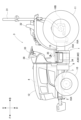
本発明の電動トラクタを例示する実施形態を図1~図8に示す電動トラクタに基づいて説明する。図1~図8において、「F」は前方向を示し、「B」は後方向を示し、「U」は上方向を示し、「D」は下方向を示し、「R」は右方向を示し、「L」は左方向を示している。
〔電動トラクタの全体構成〕
図1~図3に示すように、右及び左の前輪10が、機体1の前部に設けられ、後の走行装置である右及び左の後輪11が、機体1の後部に設けられている。機体1は、前輪10及び後輪11を支持する。
図1~図3に示すように、右及び左の前輪10が、機体1の前部に設けられ、後の走行装置である右及び左の後輪11が、機体1の後部に設けられている。機体1は、前輪10及び後輪11を支持する。
機体1は、第一前フレーム2,収容フレームA、及び、ミッションケース15を有する。収容フレームAの前部に第一前フレーム2が連結され、収容フレームAの後部にミッションケース15が連結されて、機体1のフレーム構造が構成されている。動力源としての電動モータM1及び電動モータM2が、収容フレームAに収容されている。ミッションケース15は『収容ケース』に相当する。
前車軸ケース10Aが、第一前フレーム2に取り付けられており、右及び左の前輪10が、前車軸ケース10Aに取り付けられている。左右の前輪10は前車軸ケース10Aによって支持されている。前車軸ケース10Aは左右方向に沿って延びる。前車軸ケース10Aは、左右の前輪10を支持するとともに左右の前輪10へ動力を伝達する車軸を収容する。第一前フレーム2は前車軸ケース10Aを支持する。前輪10及び前車軸ケース10Aは、『走行装置』の一例である。
ミッションケース15は左右の後輪11に動力を伝達する車軸ケースを含む。このため、ミッションケース15は左右の後輪11を支持する。右及び左の後輪11が、ミッションケース15に取り付けられている。ミッションケース15は左右の後輪11を支持する。
作業者が搭乗する運転部3が、収容フレームA及びミッションケース15の上方に設けられている。ロプスフレーム31が、ミッションケース15に取り付けられ上方に向けて延出されて、運転部3の後部に設けられている。電動モータM1,M2に電力を供給するバッテリ4が、第一前フレーム2に取り付けられており、バッテリ4を覆うボンネット12が設けられている。
バッテリ4は第一前フレーム2に載置支持されている。換言すると、第一前フレーム2はバッテリ4を下方で支持する。第一前フレーム2は、バッテリ4の支持と、前輪10の前車軸ケース10Aの支持と、に兼用されている。また、バッテリ4は第一前フレーム2よりも上側に位置する。バッテリ4は、走行用、作業用、及び、油圧駆動用の電力を蓄える。
ボンネット12は、機体左右方向に沿う横軸芯まわりに揺動可能することによって開閉可能に構成されている。ボンネット12が閉状態であるとき、バッテリ4は、ボンネット12に覆われる。
本実施形態の電動トラクタは、走行用の駆動系統と作業用の駆動系統とで独立した二個の駆動系統を有する。具体的には、図2に示すように、電動トラクタに、走行用のための電動モータM1と、作業用及び油圧駆動用のための電動モータM2と、が備えられている。また、二個の電動モータM1,M2に対応して、電動トラクタに、二個のインバータ14A,14Bが備えられている。二個の電動モータM1,M2はバッテリ4に対して機体後側に配置されている。電動モータM1は、バッテリ4から電力の供給を受けて駆動する走行用のモータである。電動モータM2は、バッテリ4から電力の供給を受けて駆動する作業用のモータである。インバータ14A,14Bは電動モータM1,M2の機体横外方に設けられている。電動モータM1は『第一電動モータ』に相当する。電動モータM2は『第二電動モータ』に相当する。
〔運転部の構成〕
図1~図3に示すように、運転部3はバッテリ4及びボンネット12の後方に設けられている。運転部3に、ロプスフレーム31、運転席32、前輪10を操向操作する操縦ハンドル33、ステップ34、フロア35、充電ソケット36、作業走行操作具37、及び、表示部38等が設けられている。運転部3は収容フレームA及びミッションケース15に支持されている。
図1~図3に示すように、運転部3はバッテリ4及びボンネット12の後方に設けられている。運転部3に、ロプスフレーム31、運転席32、前輪10を操向操作する操縦ハンドル33、ステップ34、フロア35、充電ソケット36、作業走行操作具37、及び、表示部38等が設けられている。運転部3は収容フレームA及びミッションケース15に支持されている。
足掛け用のステップ34がフロア35の右部に取り付けられており、作業者(搭乗者)は主に機体1に対して左側から運転部3に対する乗降を行う。作業者は、ステップ34から運転部3のフロア35に搭乗し、運転席32に着座可能である。
オペレータが操縦ハンドル33を操作すると、左右の前輪10は操向操作される。なお、操縦ハンドル33は、図7に示すパワーステアリングユニット27とユニバーサルジョイントを介して連結されている。
詳述はしないが、作業走行操作具37に、走行速度を調節するアクセル操作具と、後述するミッドPTO軸16A及びリヤPTO軸16Bの回転速度を調節する操作具と、が含まれる。これにより、オペレータは、運転部3において、各種の運転操作を行うことができる。なお、作業走行操作具37は、各種操作具の操作量を検出するポテンショメータを有する。
表示部38は、例えば、車体の走行状態、作業状態、バッテリ4の情報(充電量や温度)等を表示する。
充電ソケット36は、操縦ハンドル33の右方、かつ、フロア35の真上に設けられている。作業者等が充電ソケット36に充電器のアダプタを挿入すると、バッテリ4が充電される。充電ソケット36は、バッテリ4に対して充電するための受電電力を受け入れる。充電ソケット36の規格は、例えばCHAdeMO、CCS2、GB/T、ChaoJi、NACS等であって良い。
収容フレームA、電動モータM1,M2、インバータ14A,14B、及び、ミッションケース15が、フロア35よりも下側に配置されている。また、バッテリ4はフロア35よりも上側に配置されている。加えて、バッテリ4の後端部が電動モータM1,M2の前端部よりも前側に位置するように、バッテリ4が、運転部3よりも前側に設けられている。
〔収容フレームの構成〕
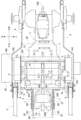
図4及び図5に示すように、収容フレームAは、前部フレーム6、ミッションケース15の前壁部分15F、右部である右の横部フレーム5、左部である左の横部フレーム5、上部フレーム19等を有する。なお、ミッションケース15の前壁部分15Fは、ミッションケース15の構成と、収容フレームAの構成と、に兼用される。前壁部分15Fは『収容ケースの前部』に相当する。
図4及び図5に示すように、収容フレームAは、前部フレーム6、ミッションケース15の前壁部分15F、右部である右の横部フレーム5、左部である左の横部フレーム5、上部フレーム19等を有する。なお、ミッションケース15の前壁部分15Fは、ミッションケース15の構成と、収容フレームAの構成と、に兼用される。前壁部分15Fは『収容ケースの前部』に相当する。
前部フレーム6及び前壁部分15Fは、上下方向及び左右方向に沿った平板状に構成されている。前部フレーム6及び前壁部分15Fは、機体1の横方向に沿って、機体1の右部と左部とに亘って延びている。右及び左の横部フレーム5は、上下方向及び前後方向に沿った平板状で少し湾曲して構成されている(図8参照)。前部フレーム6の後面部の右部分及び左部分に、横部フレーム5の前部分が連結され、前壁部分15Fの前面部の右部分及び左部分に、横部フレーム5の後部分が連結されている。
上部フレーム19が、右及び左の横部フレーム5の上部分に亘って左右方向に沿って延びている。上部フレーム19は右及び左の横部フレーム5の上部分の夫々に連結されている。
電動モータ保護部材である平板状のカバー18が、収容フレームAの底部である右及び左の横部フレーム5の下部分に亘って取り付けられ、かつ、収容フレームAの前部フレーム6及び前壁部分15Fの下部分に亘って取り付けられている。
二個の電動モータM1,M2は、平面視において、ミッションケース15の前壁部分15Fと、左右の横部フレーム5と、前部フレーム6と、に囲まれている。ミッションケース15の前壁部分15Fと、左右の横部フレーム5と、前部フレーム6と、カバー18と、上部フレーム19と、は電動モータM1,M2の収容フレームAとして構成されている。つまり、本実施形態のトラクタのフレームは、二個の電動モータM1,M2を前後、左右、上方、及び、下方から囲む収容フレームAとしても構成されている。収容フレームAは電動モータM1,M2を収容する。これにより、二個の電動モータM1,M2が異物と接触する虞が軽減される。
第一前フレーム2の後端部と前部フレーム6の前面部分とが連結されている。横部フレーム5の前端部と前部フレーム6の後面部分とが連結されている。横部フレーム5の後端部と、ミッションケース15の前壁部分15Fと、が連結されている。このことから、収容フレームAは、第一前フレーム2とミッションケース15との間に介在するフレーム体である。
〔収容フレームにおける電動モータの収容の構成〕
図1~図5に基づいて電動モータM1,M2の収容の構成について説明する。本実施形態の電動モータM1,M2は、運転部3のフロア35の下方、かつ、収容フレームAの内部(前部フレーム6と前壁部分15Fとの間、右及び左の横部フレーム5の間)に、左右に並ぶように配置されている。
図1~図5に基づいて電動モータM1,M2の収容の構成について説明する。本実施形態の電動モータM1,M2は、運転部3のフロア35の下方、かつ、収容フレームAの内部(前部フレーム6と前壁部分15Fとの間、右及び左の横部フレーム5の間)に、左右に並ぶように配置されている。
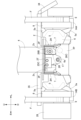
図4に示すように、バッテリ4が運転部3のフロア35よりも上側に配置され、電動モータM1と電動モータM2とがフロア35よりも下側に配置されている。なお、バッテリ4は、バッテリ4は、バッテリ4の下部が上下方向においてフロア35と同じ位置(略同じ位置を含む)に位置するように配置されている。電動モータM1,M2は、夫々の上部が上下方向においてフロア35よりも下側に位置するように配置されている。電動モータM1と電動モータM2とが第一前フレーム2に対して後側に配置されている。
電動モータM1の後端部のフランジ部が、ミッションケース15の前壁部分15Fの前面部の左部にボルトで連結されており、電動モータM2の後端部のフランジ部が、ミッションケース15の前壁部分15Fの右部にボルトで連結されている。つまり、電動モータM1,M2の夫々は、ミッションケース15の前壁部分15Fに片持ち支持されている。電動モータM1,M2の出力軸が、電動モータM1,M2の後端部のフランジ部の位置に、後方に向けて前後方向に沿って設けられている。
図4及び図5に示すように、電動モータM1の回転軸芯X1と、電動モータM2の回転軸芯X2と、の夫々は、上下方向において同一の位置に位置し、かつ、平行に同じ向きに延びる。このことから、電動モータM1の出力軸と、電動モータM2の出力軸と、が平行に同じ向きに延びる。また、前輪伝達軸17は、回転軸芯X1と回転軸芯X2との夫々に沿って延びる。即ち、電動モータM1及び電動モータM2は、夫々の出力軸が上下方向において同一(略同一を含む)の高さとなるように配置されている。また、電動モータM1及び電動モータM2は、夫々の出力軸が、同一の向き(略同一の向きを含む)に平行(略平行を含む)に延びるように配置されている。前輪伝達軸17は『伝達軸』に相当する。
図4に示すように、電動モータM1の回転軸芯X1と、電動モータM2の回転軸芯X2と、の夫々は、上下方向において第一前フレーム2における前後フレーム部2Fの下縁部と重複する位置に位置する。換言すると、電動モータM1,M2は、夫々の回転軸芯X1,X2が上下方向において前後フレーム部2Fの下縁部と同じ位置(略同じ位置を含む)に位置するように配置されている。
収容フレームAの内部において、電動モータM1が収容フレームAの前部フレーム6の凹部6a(図7及び図8参照)及び前壁部分15Fの左右中央部分に対して左側に設けられている。電動モータM2が収容フレームAの前部フレーム6の凹部6a及び前壁部分15Fの左右中央部分に対して右側に設けられている。
電動モータM1の左右幅と、電動モータM2の左右幅と、が同一である。換言すると、電動モータM1の径方向の幅、及び、電動モータM2の径方向の幅は同一(略同一を含む)である。また、電動モータM1の前後幅と、電動モータM2の前後幅と、が同一である。換言すると、電動モータM1の回転軸芯X1方向の幅、及び、電動モータM2の回転軸芯X2方向の幅は同一(略同一を含む)である。つまり、電動モータM1のサイズ、及び、電動モータM2のサイズは同一(略同一を含む)である。また、電動モータM1の容量、及び、電動モータM1の容量は同一(略同一を含む)である。これにより、電動モータM1,M2の生産コストや調達コスト等が低減され易くなる。
電動モータM1と電動モータM2との夫々のケースは円筒形に形成されている。電動モータM1と電動モータM2との夫々のケースの間にスペースが存在するように、電動モータM1及び電動モータM2は間隔を空けて配置されている。このスペースに、前輪10へ走行用の動力を伝達する前輪伝達軸17が通されている(図4及び図8参照)。
動力伝達装置Tは、走行用の動力を前輪10へ伝達するためのものである。そして、動力伝達装置Tから前方へ前輪伝達軸17が延ばされている。電動モータM1と電動モータM2の前方に、前部フレーム6、第一前フレーム2、前車軸ケース10A、及び、左右の前輪10が位置する。前輪伝達軸17は、動力伝達装置T(ミッションケース15)から、電動モータM1と電動モータM2との間のスペースと、凹部6aのスペースと、第一前フレーム2の下方のスペースと、を通されて前車軸ケース10Aへ延びる。前輪伝達軸17は、動力伝達装置Tから走行用の動力を受け取って前車軸ケース10Aへ伝達する。
前輪伝達軸17は、動力伝達装置T(ミッションケース15)と、前輪10の前車軸ケース10Aと、に亘って前後方向に延びている。つまり、第一前フレーム2の後方に電動モータM1及び動力伝達装置T(ミッションケース15)が配置され、動力伝達装置T(ミッションケース15)と前車軸ケース10Aとに亘って前輪伝達軸17が延ばされている。換言すると、第一前フレーム2において前輪伝達軸17は、電動モータM1,M2の位置する側から前車軸ケース10Aへ延ばされるとともに、前輪10へ走行用の動力を伝達する。
電動モータM1及び電動モータM2は、前輪10と動力伝達装置Tとの間に配置されている。そして前輪伝達軸17は、電動モータM1と電動モータM2との間を通されている。
〔インバータ、及び、インバータに対して機体横外側に配置された機器の構成〕
右及び左のインバータ14A,14Bが、収容フレームAの右及び左の横部フレーム5に取り付けられている。インバータ14Aは機体左側の横部フレーム5に支持され、インバータ14Bは機体右側の横部フレーム5に支持されている。つまり、インバータ14A,14Bの夫々は収容フレームAに支持されている。
右及び左のインバータ14A,14Bが、収容フレームAの右及び左の横部フレーム5に取り付けられている。インバータ14Aは機体左側の横部フレーム5に支持され、インバータ14Bは機体右側の横部フレーム5に支持されている。つまり、インバータ14A,14Bの夫々は収容フレームAに支持されている。
バッテリ4は、二個のインバータ14A,14Bへ電力を供給する。インバータ14A,14Bの夫々は、バッテリ4から直流電流を受け取って三相交流の交流電流に変換する。
作業走行操作具37における走行用の操作具の操作に基づいて、左のインバータ14Aにおいてバッテリ4の直流電力が交流電力に変換されて電動モータM1に供給される。これにより、電動モータM1が作動する。
作業走行操作具37における作業用の操作具の操作に基づいて、右のインバータ14Bにおいてバッテリ4の直流電力が交流電力に変換されて電動モータM2に供給され、電動モータM2が作動する。
インバータ14Aは、機体左側の横部フレーム5を挟んで電動モータM1の位置する側と反対側に配置されている。また、インバータ14Bは、機体右側の横部フレーム5を挟んで電動モータM2の位置する側と反対側に配置されている。つまり、電動モータM1と電動モータM2との夫々のインバータ14A,14Bが、電動モータM1及び電動モータM2に対して左右外側に配置されている。インバータ14A,14Bは、夫々の上部が上下方向においてフロア35よりも下側に位置するように配置されている。
また、インバータ14A,14Bの夫々はローダ取付部8の後方に配置されている。ローダ取付部8とインバータ14A,14Bとは前後方向に隣り合う。即ち、インバータ14Aは、左右方向において電動モータM1と隣り合い、かつ、前後方向において機体左側のローダ取付部8と隣り合う。また、インバータ14Bは、左右方向において電動モータM2と隣り合い、かつ、前後方向において機体右側のローダ取付部8と隣り合う。
インバータ14Aはステップ34に対して機体横内側に位置する。換言すると、インバータ14A,14Bは、機体側面視においてステップ34と重複する。
インバータ14Aに、電動モータM1に対する通電ケーブルを接続する通電接続口14Cが備えられている。また、インバータ14Bに、電動モータM2に対する通電ケーブルを接続する通電接続口14Dが備えられている。
通電接続口14Cはインバータ14Aの後縁部に設けられ、通電接続口14Dはインバータ14Bの後縁部に設けられている。通電接続口14Cに通電ケーブルが接続され、通電接続口14Cから通電ケーブルを介して電動モータM1に交流電力が供給される。通電接続口14Dに通電ケーブルが接続され、通電接続口14Dから通電ケーブルを介して電動モータM2に交流電力が供給される。通電接続口14C,14Dの夫々は、ローダ取付部8の位置する側と反対側に設けられている。これにより、ローダ取付部8にフロントローダFが装着される際に、フロントローダFと、通電接続口14C,14Dの夫々から延ばされる通電ケーブルと、が接触する虞が回避される。
図2及び図5に示すように、油圧配管用のバルブユニット28は、インバータ14Bに対して機体横外側で隣接し、かつ、機体右側のローダ取付部8に対して機体後側で隣接する。油圧配管用のバルブユニット28は、後述の補強ビーム9に対して機体横外側に配置されている。油圧配管用のバルブユニット28は、横部フレーム5に連結支持される構成であっても良いし、補強ビーム9に連結支持される構成であっても良い。図示はしないが、フロントローダFの右側のアームの基端部に、の油圧配管のコネクタが備えられている。バルブユニット28から延びる油圧配管が、フロントローダFの油圧配管のコネクタと接続される。つまり、バルブユニット28は、ローダ取付部8にフロントローダFが装着された際に、フロントローダFの油圧機構に油圧系統を接続可能なように構成されている。なお、機体1の後部にバックホウが装着される場合、バルブユニット28は、バックホウの油圧機構に油圧系統を接続可能な構成であっても良い。
〔作業装置を取り付けるための取付部の構成〕
図5及び図8に示すように、収容フレームAの右及び左の横部フレーム5において、上の取付部5aが横部フレーム5の前部分の上部分に斜め上向きに設けられており、下の取付部5aが横部フレーム5の前部分の下部分に斜め下向きに設けられている。
図5及び図8に示すように、収容フレームAの右及び左の横部フレーム5において、上の取付部5aが横部フレーム5の前部分の上部分に斜め上向きに設けられており、下の取付部5aが横部フレーム5の前部分の下部分に斜め下向きに設けられている。
右のローダ取付部8が、右の横部フレーム5の取付部5aに連結され、左のローダ取付部8が、左の横部フレーム5の取付部5aに連結されている。後述するように、フロントローダF等の作業装置(図3参照)が、右及び左のローダ取付部8に取り付けられる。左右のローダ取付部8の夫々は、フロントローダF等の作業装置を着脱可能なように支持する。
左右の横部フレーム5の夫々の前部に、ローダ取付部8が支持されている。左右のローダ取付部8の夫々は、横部フレーム5よりも機体横外側に位置する。また、左右のローダ取付部8の夫々の前端部は、横部フレーム5よりも前側に位置する。左右のローダ取付部8の夫々は、前部フレーム6の横外端部に隣接する。
機体左側のローダ取付部8は、ステップ34に対して前側で隣り合う。前後方向においてローダ取付部8は、前輪10とステップ34との間に配置されている。また、ローダ取付部8は、前後方向においてバッテリ4と電動モータM1,M2との間に配置されている。ローダ取付部8は、左右方向においてバッテリ4よりも機体横外側に配置されている。
電動トラクタにフロントローダFが装着されると、図3に示すように、フロントローダFの基端部とローダ取付部8とが連結される。このとき、フロントローダFの基端部に、補強ビーム9の前端部が連結される。フロントローダFの基端部は、左右方向においてローダ取付部8と補強ビーム9の前端部とに挟まれる。そして左右の補強ビーム9は前後に延び、左右の補強ビーム9の夫々の後端部がミッションケース15における後輪11の車軸ケースに支持されている。左右の補強ビーム9は、ミッションケース15を機体横外側から前後に亘って覆う。この構成によって、フロントローダFのモーメント荷重に対する耐久性が強化されている。つまり、左右の補強ビーム9は、ローダ取付部8と動力伝達装置Tとの夫々に連結されるとともに、フロントローダFを支持するためのローダ取付部8の支持構造を補強する。また、インバータ14A,14Bは、左右の補強ビーム9よりも機体横内側に位置する。
〔前フレーム及び前車軸ケースの構成〕
図4及び図5に示すように、電動トラクタに右及び機体左側の第一前フレーム2が設けられている。第一前フレーム2が収容フレームAの前部フレーム6の前面部の上部分に連結されて、前方に向けて延出されている。
図4及び図5に示すように、電動トラクタに右及び機体左側の第一前フレーム2が設けられている。第一前フレーム2が収容フレームAの前部フレーム6の前面部の上部分に連結されて、前方に向けて延出されている。
図4に示すように、第一前フレーム2の前後中央部分と、前部フレーム6の下部と、に亘って第二前フレーム7が連結されている。収容フレームAの前部フレーム6の前面部の下部分において、第一前フレーム2の下方の部分に、第二前フレーム7の後部が連結されている。第二前フレーム7の前部が第一前フレーム2の前後中間部に連結されている。
バッテリ4が、第一前フレーム2の上部に取り付けられており、バッテリ4の後端部が電動モータM1,M2の前端部よりも前側に設けられている。前車軸ケース10Aの前後中央、かつ、左右中央の箇所が、第一前フレーム2の前部の下部にローリング可能に取り付けられている。第一前フレーム2は左右の前輪10に対してローリング可能である。前車軸ケース10A(前輪10)は、バッテリ4の下方に設けられ、かつ、電動モータM1,M2よりも前側に設けられている。
平板状のカバー7Pが、右及び左の第二前フレーム7に亘って取り付けられている。機体側面視において、第二前フレーム7及びカバー7Pの前部が、第二前フレーム7及びカバー7Pの後部よりも高い。つまり、第二前フレーム7及びカバー7Pは、前上がり傾斜姿勢となっている。
第一前フレーム2の後端部は前部フレーム6の上部に連結されている。第一前フレーム2と前部フレーム6と第二前フレーム7とによって、機体側面視において三角形状のフレームが形成されている。これにより、トラクタの機体前部におけるフレーム構造が強化されている。
左右の第一前フレーム2、左右の第二前フレーム7、及び、カバー7Pは、同じ左右方向の横幅W2を有する。収容フレームAの左右方向の横幅W1は、左右の第一前フレーム2、左右の第二前フレーム7、及び、カバー7Pの左右方向の横幅W2よりも大きい。
平面視で、電動モータM1の回転軸芯X1は、機体1の左右方向において、機体左側の第一前フレーム2、及び、機体左側の第二前フレーム7に近接する。また、電動モータM2の回転軸芯X2は、機体1の左右方向において、機体右側の第一前フレーム2、及び、機体右側の第二前フレーム7に近接する。これにより、左右の第一前フレーム2、左右の第二前フレーム7、及び、カバー7Pの左右方向の横幅W2と、電動モータM1,M2の出力軸の回転軸芯X1,X2の左右方向の横幅(間隔)と、は略同じである。
〔動力伝達装置の構成〕
図6に示すように、動力伝達装置Tに、走行用の動力伝達機構15Aと、作業用の動力伝達機構15Bと、油圧ポンプ15Cと、が備えられている。ミッションケース15は、走行用の動力伝達機構15Aと、作業用の動力伝達機構15Bと、油圧ポンプ15Cと、を収容する。つまり、動力伝達装置Tは、ミッションケース15と、走行用の動力伝達機構15Aと、作業用の動力伝達機構15Bと、油圧ポンプ15Cと、を有する。走行用の動力伝達機構15Aは『第一動力伝達機構』に相当する。作業用の動力伝達機構15Bは『第二動力伝達機構』に相当する。油圧ポンプ15Cは『作業用出力部』の一例である。
図6に示すように、動力伝達装置Tに、走行用の動力伝達機構15Aと、作業用の動力伝達機構15Bと、油圧ポンプ15Cと、が備えられている。ミッションケース15は、走行用の動力伝達機構15Aと、作業用の動力伝達機構15Bと、油圧ポンプ15Cと、を収容する。つまり、動力伝達装置Tは、ミッションケース15と、走行用の動力伝達機構15Aと、作業用の動力伝達機構15Bと、油圧ポンプ15Cと、を有する。走行用の動力伝達機構15Aは『第一動力伝達機構』に相当する。作業用の動力伝達機構15Bは『第二動力伝達機構』に相当する。油圧ポンプ15Cは『作業用出力部』の一例である。
走行用の動力伝達機構15Aは、電動モータM1から回転動力を受け取り、当該回転動力をギヤ式変速機構で変速しながら左右の前輪10、及び、左右の後輪11へ伝達する。これにより、左右の前輪10、及び、左右の後輪11は、電動モータM1からの走行用の動力で回転駆動する。つまり、走行用の動力伝達機構15Aは、走行用の動力を電動モータM1から前輪10及び後輪11へ伝達する。換言すると、左右の前輪10、及び、左右の後輪11は、走行用の電力に基づいて駆動する。
また、電動トラクタに、ミッドPTO軸16AとリヤPTO軸16Bとが備えられている。作業用の動力伝達機構15Bは、電動モータM2から回転動力を受け取り、当該回転動力をミッドPTO軸16A、及び、リヤPTO軸16Bへ分配する。これにより、ミッドPTO軸16A及びリヤPTO軸16Bが回転駆動する。
ミッドPTO軸16AまたはリヤPTO軸16Bに作業装置が接続されていれば、ミッドPTO軸16A、または、リヤPTO軸16Bの回転動力によって、作業装置が駆動する。つまり、作業用の動力伝達機構15Bは、作業用の動力を電動モータM2からミッドPTO軸16A、及び、リヤPTO軸16Bへ伝達する。そして、ミッドPTO軸16A、及び、リヤPTO軸16Bは、作業用の動力を作業装置へ供給する。
油圧ポンプ15Cは、電動モータM2から回転動力を受け取って回転駆動する。油圧ポンプ15Cは、電動トラクタにおける油圧系統の駆動源である。このため、例えばトラクタにフロントローダFが装着されていると、油圧ポンプ15Cによって作動油が圧送され、フロントローダFは作動油の油圧に基づいて作動する。つまり、油圧ポンプ15C、作業用の油圧を作業装置へ供給する。
このように、動力伝達装置Tは、走行用の動力伝達と作業用の動力伝達と油圧駆動用とに兼用されている。つまり、動力伝達装置Tに、電動モータM1からの動力を前輪10及び後輪11へ伝達する走行用の動力伝達機構15Aと、電動モータM2からの動力をミッドPTO軸16A、及び、リヤPTO軸16Bへ伝達する作業用の動力伝達機構15Bと、油圧駆動用の油圧ポンプ15Cと、が備えられている。また、動力伝達装置Tは、電動モータM1及び電動モータM2の後方に配置されている。
ミッドPTO軸16Aと接続される作業装置は、例えば草刈装置、ロータリーレーキ、切葉装置、散布装置等であっても良い。また、ミッドPTO軸16Aは、機体1の前部に装着される作業装置のためのフロントPTO軸として用いられても良い。リヤPTO軸16Bと接続される作業装置は、カルティベータ、播種装置、プランタ、施肥装置、切葉装置、散布装置、草刈装置、ベーラー、マルチャー、ストーンピッカー、ロータリーレーキ、及び、テッダー、牽引式の収穫選別装置、摘芯装置、中耕管理装置、畝立装置、等であっても良い。
〔電動トラクタの駆動システムについて〕
図6に示すように、作業走行操作具37の操作に応じて電動モータM1,M2の駆動を制御する制御装置20が備えられている。制御装置20は、電動トラクタの制御系の中核要素であり、複数のECUの集合体として構成されている。
図6に示すように、作業走行操作具37の操作に応じて電動モータM1,M2の駆動を制御する制御装置20が備えられている。制御装置20は、電動トラクタの制御系の中核要素であり、複数のECUの集合体として構成されている。
制御装置20は、例えばCAN(Controller Area Network)方式の信号用ハーネス21を介して、バッテリ4の充放電制御部4A、インバータ14A,14B、電動モータM1,M2、充電制御部22、DC/DCコンバータ23、作業走行操作具37、及び、表示部38等とデータを通信可能に接続されている。
制御装置20は、作業走行操作具37の指令に応じて、インバータ14A,14Bに指令信号を出力する。インバータ14Aは、制御装置20の指令信号に応じて、バッテリ4から電動モータM1に供給される三相交流の電力(電圧値、周波数、及び、電流値等)を調整して電動モータM1の出力を制御する。同様に、インバータ14Bは、制御装置20の指令信号に応じて、バッテリ4から電動モータM2に供給される三相交流の電力を調整して電動モータM2の出力を制御する。
制御装置20は表示部38の作動を制御する。このため、表示部38に、電動モータM1,M2の作動状況やバッテリ4の情報等が表示される。
バッテリ4は、例えばリチウムイオンバッテリである。図示はしないが、バッテリ4は、低電圧の小型の単位電池(セル)を多数積層した状態で構成されている。バッテリ4の出力電圧は、例えば400ボルトである。単位電池(セル)は収納ケースによって収納されている。これら単位電池(セル)は、当該収納ケースによって密閉されている。
バッテリ4は電源分配ユニット13と通電接続されている。また、電源分配ユニット13は、インバータ14A,14Bと、DC/DCコンバータ23と、の夫々にも通電接続されている。このため、電源分配ユニット13は、バッテリ4からの電力を、インバータ14A,14Bと、DC/DCコンバータ23と、の夫々に分配するハブとして機能する。また、電源分配ユニット13は、充電制御部22を介して充電ソケット36とも接続されている。電源分配ユニット13は、充電ソケット36からの充電電力を受け取ってバッテリ4へ送電するように構成されている。
バッテリ4に充放電制御部4Aが備えられている。充放電制御部4Aは、バッテリ4の出力電圧、受電電圧、及び、発熱温度等に基づいてバッテリ4の放電電流や充電電流等を制御するように構成されている。
バッテリ4はインバータ14A,14Bに大きな電力を出力するため、バッテリ4の発熱量も大きくなる。また、バッテリ4の充電量や放電量を適切に管理するための温度管理も重要になる。このため、バッテリ4の内部には水冷式の調温流路が実装されている。この調温流路に液体の冷媒を供給するためのバッテリ調温装置25が、バッテリ4の近傍に備えられている。
バッテリ調温装置25に、バッテリ用ラジエータ25Aと、リザーバータンク25Bと、バッテリ用ヒータ25Cと、ポンプ25Dと、が備えられている。リザーバータンク25Bに冷媒が貯蔵されている。ポンプ25Dはバッテリ4を冷却する冷媒を圧送する。バッテリ用ヒータ25Cは、冷媒を温めることによってバッテリ4を昇温させる。ポンプ25Dが稼働すると、冷媒は、リザーバータンク25Bから、バッテリ用ヒータ25C、ポンプ25D、バッテリ4の内部の調温流路、及び、バッテリ用ラジエータ25Aの順に循環する。これにより、バッテリ調温装置25は、バッテリ4の温度を調節するように構成されている。
バッテリ用ヒータ25Cは、ポンプ25Dと、バッテリ4の内部の調温流路の入口と、の間に設けられている。バッテリ4の温度が低温であると、バッテリ4の充放電の電流は少なくなる。このような状態で電動トラクタが起動されるとき、充放電制御部4Aはバッテリ用ヒータ25Cを稼働させ、冷媒を温める。これにより、バッテリ4の温度が、充放電に適切な温度に素早く昇温される。
バッテリ用ラジエータ25Aは、バッテリ4の内部の調温流路の出口と、リザーバータンク25Bと、の間に設けられている。このため、バッテリ4の内部の調温流路で熱せられた冷媒が、バッテリ用ラジエータ25Aで冷却され、リザーバータンク25Bに戻される。
充電制御部22の回路は、充電ソケット36と電源分配ユニット13との夫々に通電接続されている。充電制御部22は、例えば制御装置20からの制御信号に基づいてプログラムを実行するマイクロコンピュータを有するパワーモジュールやPLC(プログラマブル・ロジック・コントローラ)であっても良いし、制御装置20からの電気信号に基づいて作動するリレー回路であっても良い。充電制御部22は、バッテリ4を充電(急速充電を含む)する際のバッテリ4に対する充電電圧や充電電流を制御する。充電制御部22は、充電ソケット36からの受電電力を調節してバッテリ4に充電電力として供給する。
電動トラクタには、バッテリ4の他に、制御装置20及びその他の電装品に電力を供給する電装品用バッテリ24が備えられている。電装品用バッテリ24は、例えば鉛バッテリである。電装品用バッテリ24は、電装品を駆動するために低電圧(例えば12ボルト)の電力を供給する。電装品用バッテリ24の出力電圧はバッテリ4の出力電圧よりも低い。
電装品用バッテリ24は、DC/DCコンバータ23を介してバッテリ4から供給される電力にて充電される。DC/DCコンバータ23は、バッテリ4の電圧を電装品用バッテリ24の電圧に降下したうえで、低電圧の電装品へ電力を供給可能である。また、DC/DCコンバータ23は、電装品用バッテリ24へも電力を供給可能である。つまり、DC/DCコンバータ23は、バッテリ4と電装品用バッテリ24との夫々に対して通電可能に接続され、バッテリ4からの電力を受電し、電圧降下して電装品用バッテリ24へ送電可能である。このことから、バッテリ4は、電装品用バッテリ24へ電力を供給し、電装品用バッテリ24を充電可能である。換言すると、電装品用バッテリ24は、DC/DCコンバータ23を介してバッテリ4から受電した電力で充電可能である。
バッテリ4からの電力を高電圧で受電する強電系の装置は、発熱によって高温になりがちである。このため、電動トラクタに、強電系の装置を冷却するための高圧機器用冷却装置26が備えられている。高圧機器用冷却装置26に、高圧機器用ラジエータ26Aと、ポンプ26B,26Cと、が備えられている。ポンプ26B,26Cは直列に接続されている。ポンプ26B,26Cは、インバータ14A,14B、電動モータM1,M2、DC/DCコンバータ23等の、電力に基づいて稼働する強電系の装置を冷却する冷媒を圧送する。ポンプ26B,26Cが稼働すると、冷媒は、インバータ14A,14B、電動モータM1,M2、DC/DCコンバータ23等の強電系の機器における冷却流路を流れて、当該強電系の装置を冷却する。そして当該強電系の装置によって熱せられた冷媒は、高圧機器用ラジエータ26Aによって冷却される。なお、強電系の装置における冷却流路の順番は、適宜変更可能である。
〔前フレームにおけるバッテリ支持の補強構造〕
上述の通り、バッテリ4は第一前フレーム2及び第二前フレーム7に支持されている。図7及び図8に示すように、第一前フレーム2に、左右の前後フレーム部2Fと、左右の内側補強フレーム2Rと、左右の補助フレーム2Hと、カバー2Pと、連結プレート2Tと、が備えられている。機体右側の前後フレーム部2Fは、バッテリ4の機体右部分を下方で支持する。機体左側の前後フレーム部2Fは、バッテリ4の機体左部分を下方で支持する。図示はしないが、左右の前後フレーム部2Fは、左右の前後フレーム部2Fの夫々に連結されて左右に延びる横架フレームを介して、前車軸ケース10Aをローリング可能に支持する。つまり、左右の前後フレーム部2Fは、バッテリ4の支持と、前車軸ケース10Aの支持と、に兼用されている。
上述の通り、バッテリ4は第一前フレーム2及び第二前フレーム7に支持されている。図7及び図8に示すように、第一前フレーム2に、左右の前後フレーム部2Fと、左右の内側補強フレーム2Rと、左右の補助フレーム2Hと、カバー2Pと、連結プレート2Tと、が備えられている。機体右側の前後フレーム部2Fは、バッテリ4の機体右部分を下方で支持する。機体左側の前後フレーム部2Fは、バッテリ4の機体左部分を下方で支持する。図示はしないが、左右の前後フレーム部2Fは、左右の前後フレーム部2Fの夫々に連結されて左右に延びる横架フレームを介して、前車軸ケース10Aをローリング可能に支持する。つまり、左右の前後フレーム部2Fは、バッテリ4の支持と、前車軸ケース10Aの支持と、に兼用されている。
前後フレーム部2Fは機体1の前後方向に沿って延び、前後フレーム部2Fの前後中央部分の下方に前車軸ケース10Aが位置する。換言すると、前後フレーム部2Fは、前後中央部分において前車軸ケース10Aを支持する状態で前後に延びる。
バッテリ4の重量は、バッテリ4の容量が大きくなるほど重たくなりがちである。図5、図7及び図8に示すように、本実施形態では、機体左側の前後フレーム部2Fの後部に機体左側の内側補強フレーム2Rが連結され、機体右側の前後フレーム部2Fの後部に機体右側の内側補強フレーム2Rが連結されている。図7及び図8では、左右の内側補強フレーム2Rが、太線で囲まれた状態で示されている。
内側補強フレーム2Rの後端部は横方向に延びる前部フレーム6に連結されている。左右の内側補強フレーム2Rの夫々は、前部と後部とに亘って、機体横外側に隣接する前後フレーム部2Fと連結されている。換言すると、内側補強フレーム2Rの前部と後部とに亘って前後フレーム部2Fが支持されている。
左右の内側補強フレーム2Rは左右の前後フレーム部2Fに対して機体横内側に位置する。換言すると、第一前フレーム2における左右の前後フレーム部2Fは内側補強フレーム2Rに対して機体横外側に位置する。
左右の内側補強フレーム2Rの夫々は、後側ほど左右に肉厚になるように形成されている。つまり、左右の内側補強フレーム2Rは、機体1の左右方向における夫々の幅が後側(前部フレーム6の位置する側)ほど広くなるように形成されている。左右の内側補強フレーム2Rの夫々の後部は、上下方向において前部よりも下側に延ばされている。換言すると、左右の内側補強フレーム2Rの夫々の後部は、上下方向において前部よりも肉厚になるように形成されている。このように、左右の内側補強フレーム2Rの夫々は、機体横外側に隣接する前後フレーム部2Fに連結されるとともにバッテリ4の支持構造を補強する。
左右の内側補強フレーム2Rの夫々に延出部2sが備えられている。左右の内側補強フレーム2Rの夫々の上部に延出部2sが形成され、延出部2sは機体左右方向に沿って機体横内方に延ばされている。この延出部2sに、平板状の連結プレート2Tが連結されている。この構成によって、第一前フレーム2の後部における剛性が高められている。
内側補強フレーム2Rの前端部は前車軸ケース10Aよりも後側に位置する。内側補強フレーム2Rの前部は、前後方向において第二前フレーム7の前部と重複する。内側補強フレーム2Rの前部と第二前フレーム7の前部との夫々が位置する箇所に補助フレーム2Hが備えられている。補助フレーム2Hは、前後フレーム部2Fと内側補強フレーム2Rと第二前フレーム7との夫々に連結されている。つまり、内側補強フレーム2Rの前部と第二前フレーム7の前部との夫々が、補助フレーム2Hを介して互いに連結されている。これにより、第一前フレーム2の後部における支持構造が強化されている。
〔前フレームにおける冷媒用機器の支持構造〕
図7及び図8に示すように、本実施形態では、バッテリ4と前車軸ケース10Aとの間、かつ、第一前フレーム2の左右の前後フレーム部2Fの間の空間に、ポンプ26B,26C、及び、バッテリ用ヒータ25Cが配置されている。ポンプ26B,26C、及び、バッテリ用ヒータ25Cは、上下方向において、バッテリ4と、前後に延びる前輪伝達軸17と、の間に配置されている。ポンプ25D,ポンプ26B,26C、及び、バッテリ用ヒータ25Cは、バッテリ4の下方、かつ、電動モータM1,M2に対して機体前側に配置されている。
図7及び図8に示すように、本実施形態では、バッテリ4と前車軸ケース10Aとの間、かつ、第一前フレーム2の左右の前後フレーム部2Fの間の空間に、ポンプ26B,26C、及び、バッテリ用ヒータ25Cが配置されている。ポンプ26B,26C、及び、バッテリ用ヒータ25Cは、上下方向において、バッテリ4と、前後に延びる前輪伝達軸17と、の間に配置されている。ポンプ25D,ポンプ26B,26C、及び、バッテリ用ヒータ25Cは、バッテリ4の下方、かつ、電動モータM1,M2に対して機体前側に配置されている。
冷媒用のポンプ25D,26Bの夫々は機体左側の前後フレーム部2Fにボルト固定されている。また、ポンプ26Cは機体左側の第二前フレーム7にボルト固定されている。ポンプ26Bはポンプ25Dの後方に配置され、ポンプ26Cはポンプ26Bの後方に配置されている。なお、ポンプ25Dの右方に、パワーステアリングユニット27が配置されている。
バッテリ用ヒータ25C、ポンプ25D及びポンプ26Bの夫々は、左右方向において左右の前後フレーム部2Fの間に配置されている。また、バッテリ用ヒータ25C、ポンプ25D及びポンプ26Bの夫々は、上下方向において、機体左側の前後フレーム部2Fの上縁部と下縁部との間、かつ、機体右側の前後フレーム部2Fの上縁部と下縁部との間に配置されている。この状態で、左右の前後フレーム部2Fの下縁部の夫々にカバー2Pが連結されている。カバー2Pは、バッテリ4の下方、かつ、左右の前後フレーム部2Fの間の空間を下方から覆う。このため、ポンプ25Dは、左右の前後フレーム部2Fと、バッテリ4と、カバー2Pと、によって、上下左右を囲まれる。これにより、ポンプ25Dは上下方向及び左右方向において異物と接触し難くなる。
バッテリ用ヒータ25Cは、連結プレート2Tの下面部分にボルト固定されている。つまり、バッテリ用ヒータ25Cは連結プレート2Tを介して左右の内側補強フレーム2Rに支持されている。また、第一前フレーム2の前部にポンプ25Dが配置されている。つまり、第一前フレーム2にバッテリ調温装置25のバッテリ用ヒータ25C及びポンプ25Dが支持されている。
バッテリ用ヒータ25C及びポンプ25D,26Bは、左右方向において左右の内側補強フレーム2Rの間に配置され、かつ、上下方向において左右の内側補強フレーム2Rの上縁部と下縁部との間に位置する。また、バッテリ用ヒータ25C及びポンプ25D,26Bは、上下方向においてバッテリ4と前車軸ケース10Aとの間に配置されている。加えて、バッテリ用ヒータ25C及びポンプ26Bは、前後方向において電動モータM1,M2と前車軸ケース10Aとの間に配置されている。
ポンプ26Cは、左右の第二前フレーム7の下縁部に対して上側に位置するように配置されている。この状態で、左右の第二前フレーム7の下縁部の夫々にカバー7Pが連結されている。カバー7Pは、バッテリ4の下方、かつ、左右の第二前フレーム7の間の空間を下方から覆う。この構成によって、ポンプ26B,26C及びバッテリ用ヒータ25Cは、左右の前後フレーム部2Fと、左右の第二前フレーム7と、バッテリ4と、連結プレート2Tと、カバー7Pと、によって、上下左右を囲まれる。これにより、ポンプ26B,26C及びバッテリ用ヒータ25Cの夫々は上下方向及び左右方向において異物と接触し難くなる。
〔別実施形態〕
本発明は、上述の実施形態に例示された構成に限定されるものではなく、以下、本発明の代表的な別実施形態を例示する。
本発明は、上述の実施形態に例示された構成に限定されるものではなく、以下、本発明の代表的な別実施形態を例示する。
(1)上述の実施形態では、走行用のための電動モータM1のサイズ、及び、作業用及び油圧駆動用のための電動モータM2のサイズは同一であるが、略同一であっても良い。具体的には、電動モータM1の径方向の幅、及び、電動モータM2の径方向の幅が略同一であっても良いし、電動モータM1の回転軸芯X1方向の幅、及び、電動モータM2の回転軸芯X2方向の幅が略同一であっても良い。また、電動モータM1と電動モータM2との型式が異なっていても良いし、電動モータM1と電動モータM2との容量が異なっていても良い。
(2)上述の実施形態では、電動モータM1及び電動モータM2は、前壁部分15Fに片持ち支持されているが、この実施形態に限定されない。例えば、電動モータM1と電動モータM2との夫々の前部は、前部フレーム6に支持される構成であっても良いし、第一前フレーム2に支持される構成であっても良い。
(3)上述の実施形態では、動力伝達装置Tは、電動モータM1及び電動モータM2の後方に配置されているが、この実施形態に限定されない。例えば、電動トラクタが四輪操舵仕様である場合、動力伝達装置Tは、電動モータM1及び電動モータM2の前方に配置される構成であっても良いし、電動モータM1と電動モータM2との間に配置される構成であっても良い。また、前輪伝達軸17が電動モータM1と電動モータM2との間を通されていなくても良い。また、『伝達軸』は後輪11へ伝達する軸であっても良い。
(4)上述の実施形態では、走行用の動力伝達系統と作業用の動力伝達系統との夫々は、完全に独立した駆動系として構成されているが、この実施形態に限定されない。例えば、走行用の動力伝達機構15Aと、作業用の動力伝達機構15Bと、の間にクラッチが介在し、走行用のための電動モータM1が、作業用及び油圧駆動用のための電動モータM2のトルクをアシスト可能な構成であっても良い。また、作業用及び油圧駆動用のための電動モータM2が、走行用のための電動モータM1のトルクをアシスト可能な構成であっても良い。
(5)上述の実施形態では、『走行装置』は前輪10及び前車軸ケース10Aである。この実施形態に限定されず、『走行装置』はクローラ(セミクローラを含む)を有する転輪機構であっても良い。
(6)上述の実施形態では、電動モータM2は、作業用と油圧駆動用とに兼用されている。この実施形態に限定されず、電動モータM2は、作業用と油圧駆動用との一方に用いられる構成であっても良い。
(7)上述の実施形態では、バッテリ4は走行用と作業用と油圧駆動用とのための電力を蓄える。この実施形態に限定されず、例えば第一前フレーム2に支持されるバッテリ4は、走行用と作業用と油圧駆動用との少なくとも一つのための電力を蓄える構成であっても良い。この場合、当該少なくとも一つに該当しない電力を蓄えるバッテリが、電動トラクタの他の箇所に配置される構成であっても良い。
なお、上述の実施形態(別実施形態を含む、以下同じ)で開示される構成は、矛盾が生じない限り、他の実施形態で開示される構成と組み合わせて適用することが可能である。また、本明細書において開示された実施形態は例示であって、本発明の実施形態はこれに限定されず、本発明の目的を逸脱しない範囲内で適宜改変することが可能である。
本発明は、電動トラクタに適用可能である。
3 :運転部
4 :バッテリ
10 :前輪(走行装置)
10A :前車軸ケース(走行装置)
15 :ミッションケース(収容ケース)
15A :動力伝達機構(第一動力伝達機構)
15B :動力伝達機構(第二動力伝達機構)
15C :油圧ポンプ(作業用出力部)
15F :前壁部分(収容ケースの前部)
16A :ミッドPTO軸(作業用出力部)
16B :リヤPTO軸(作業用出力部)
17 :前輪伝達軸(伝達軸)
35 :フロア
M1 :電動モータ(第一電動モータ)
M2 :電動モータ(第二電動モータ)
T :動力伝達装置
X1 :第一電動モータの回転軸芯
X2 :第二電動モータの回転軸芯
4 :バッテリ
10 :前輪(走行装置)
10A :前車軸ケース(走行装置)
15 :ミッションケース(収容ケース)
15A :動力伝達機構(第一動力伝達機構)
15B :動力伝達機構(第二動力伝達機構)
15C :油圧ポンプ(作業用出力部)
15F :前壁部分(収容ケースの前部)
16A :ミッドPTO軸(作業用出力部)
16B :リヤPTO軸(作業用出力部)
17 :前輪伝達軸(伝達軸)
35 :フロア
M1 :電動モータ(第一電動モータ)
M2 :電動モータ(第二電動モータ)
T :動力伝達装置
X1 :第一電動モータの回転軸芯
X2 :第二電動モータの回転軸芯
Claims (13)
- 電力を蓄えるバッテリと、
前記バッテリから電力の供給を受けて駆動する走行用のための第一電動モータと、
前記バッテリから電力の供給を受けて駆動する作業用と油圧駆動用との少なくとも一方のための第二電動モータと、が備えられ、
前記第一電動モータのサイズ、及び、前記第二電動モータのサイズは同一または略同一である電動トラクタ。 - 前記第一電動モータの容量、及び、前記第二電動モータの容量は同一または略同一である請求項1に記載の電動トラクタ。
- 前記走行用と前記作業用との少なくとも一方の動力を伝達する動力伝達装置が備えられ、
前記動力伝達装置は、前記第一電動モータ及び前記第二電動モータの後方に配置されている請求項1または2に記載の電動トラクタ。 - 前記動力伝達装置は、前記動力を伝達する動力伝達機構と、前記動力伝達機構を収容する収容ケースを有し、
前記第一電動モータ及び前記第二電動モータは、前記収容ケースの前部に片持ち支持されている請求項3に記載の電動トラクタ。 - 前記走行用の動力で駆動する走行装置と、
前記作業用の動力を作業装置へ供給する作業用出力部と、が備えられ、
前記動力伝達装置に、前記第一電動モータからの動力を前記走行装置へ伝達する第一動力伝達機構と、前記第二電動モータからの動力を前記作業用出力部へ伝達する第二動力伝達機構と、が備えられている請求項3または4に記載の電動トラクタ。 - 前記第一電動モータ及び前記第二電動モータは、夫々の出力軸が上下方向において同一または略同一の高さとなるように配置されている請求項1から5の何れか一項に記載の電動トラクタ。
- 前記第一電動モータ及び前記第二電動モータは、夫々の出力軸が、同一の向きに平行、または、略同一の向きに略平行に延びるように配置されている請求項1から6の何れか一項に記載の電動トラクタ。
- 前記第一電動モータ及び前記第二電動モータは、互いに左右に並ぶように配置されている請求項1から7の何れか一項に記載の電動トラクタ。
- 搭乗者が搭乗するフロアを有する運転部が備えられ、
前記第一電動モータ及び前記第二電動モータは、夫々の上部が上下方向において前記フロアと同じまたは前記フロアよりも下側に位置するように配置されている請求項8に記載の電動トラクタ。 - 前記第一電動モータの径方向の幅、及び、前記第二電動モータの径方向の幅は同一または略同一である請求項8または9に記載の電動トラクタ。
- 前記第一電動モータの軸芯方向の幅、及び、前記第二電動モータの軸芯方向の幅は同一または略同一である請求項8から10の何れか一項に記載の電動トラクタ。
- 前記走行用の動力で駆動する走行装置と、
前記走行用の動力を前記走行装置へ伝達するための動力伝達装置と、
前記動力伝達装置から前記走行用の動力を受け取って前記走行装置へ伝達する伝達軸と、が備えられ、
前記第一電動モータ及び前記第二電動モータは、前記走行装置と前記動力伝達装置との間に配置され、
前記伝達軸は、前記第一電動モータと前記第二電動モータとの間を通されている請求項8から11の何れか一項に記載の電動トラクタ。 - 前記第一電動モータ及び前記第二電動モータは、前記バッテリに対して機体後側に配置されている請求項1から12の何れか一項に記載の電動トラクタ。
Applications Claiming Priority (2)
| Application Number | Priority Date | Filing Date | Title |
|---|---|---|---|
| JP2023-221312 | 2023-12-27 | ||
| JP2023221312 | 2023-12-27 |
Publications (1)
| Publication Number | Publication Date |
|---|---|
| WO2025142149A1 true WO2025142149A1 (ja) | 2025-07-03 |
Family
ID=96218864
Family Applications (1)
| Application Number | Title | Priority Date | Filing Date |
|---|---|---|---|
| PCT/JP2024/039808 Pending WO2025142149A1 (ja) | 2023-12-27 | 2024-11-08 | 電動トラクタ |
Country Status (1)
| Country | Link |
|---|---|
| WO (1) | WO2025142149A1 (ja) |
Citations (4)
| Publication number | Priority date | Publication date | Assignee | Title |
|---|---|---|---|---|
| JP2008306813A (ja) * | 2007-06-06 | 2008-12-18 | Komatsu Ltd | 電動車両の駆動装置 |
| JP2013034439A (ja) * | 2011-08-09 | 2013-02-21 | Mitsubishi Agricultural Machinery Co Ltd | 乗用田植機 |
| JP2016193651A (ja) * | 2015-03-31 | 2016-11-17 | 株式会社 神崎高級工機製作所 | 移動体用モータユニット |
| WO2021131249A1 (ja) * | 2019-12-26 | 2021-07-01 | 株式会社クボタ | 電動作業車 |
-
2024
- 2024-11-08 WO PCT/JP2024/039808 patent/WO2025142149A1/ja active Pending
Patent Citations (4)
| Publication number | Priority date | Publication date | Assignee | Title |
|---|---|---|---|---|
| JP2008306813A (ja) * | 2007-06-06 | 2008-12-18 | Komatsu Ltd | 電動車両の駆動装置 |
| JP2013034439A (ja) * | 2011-08-09 | 2013-02-21 | Mitsubishi Agricultural Machinery Co Ltd | 乗用田植機 |
| JP2016193651A (ja) * | 2015-03-31 | 2016-11-17 | 株式会社 神崎高級工機製作所 | 移動体用モータユニット |
| WO2021131249A1 (ja) * | 2019-12-26 | 2021-07-01 | 株式会社クボタ | 電動作業車 |
Similar Documents
| Publication | Publication Date | Title |
|---|---|---|
| EP4173865A1 (en) | Electric tractor | |
| EP3678892B1 (en) | Agricultural vehicle having electrical drive line | |
| JP7313109B2 (ja) | 電動草刈機 | |
| JP7769113B2 (ja) | 作業車両 | |
| US12151584B2 (en) | Working vehicle | |
| US20250031593A1 (en) | Platform structure of electrically-driven tractor | |
| CN119421800A (zh) | 作业车辆 | |
| US10667464B2 (en) | Mower unit | |
| JP7763345B2 (ja) | 作業車両 | |
| WO2024004906A1 (ja) | 作業車両 | |
| WO2024004915A1 (ja) | 農業用作業車両 | |
| WO2024004914A1 (ja) | 農業トラクタ | |
| WO2025142171A1 (ja) | 電動トラクタ | |
| WO2025142186A1 (ja) | 電動トラクタ | |
| WO2025142202A1 (ja) | 電動トラクタ | |
| US12409740B2 (en) | Electric work vehicle | |
| TW202517134A (zh) | 作業車輛 | |
| JP2024047247A (ja) | 作業車 | |
| TW202517133A (zh) | 作業車輛 | |
| US20240270318A1 (en) | Electric work vehicle | |
| JP2025028587A (ja) | 電動車両 | |
| WO2024004907A1 (ja) | 作業車両 | |
| WO2023119834A1 (ja) | 電動作業車 | |
| WO2024004905A1 (ja) | 作業車両 | |
| WO2025142225A1 (ja) | 電動トラクタ |
Legal Events
| Date | Code | Title | Description |
|---|---|---|---|
| 121 | Ep: the epo has been informed by wipo that ep was designated in this application |
Ref document number: 24912042 Country of ref document: EP Kind code of ref document: A1 |