WO2025142121A1 - 電力伝送装置および電力伝送システム - Google Patents
電力伝送装置および電力伝送システム Download PDFInfo
- Publication number
- WO2025142121A1 WO2025142121A1 PCT/JP2024/039110 JP2024039110W WO2025142121A1 WO 2025142121 A1 WO2025142121 A1 WO 2025142121A1 JP 2024039110 W JP2024039110 W JP 2024039110W WO 2025142121 A1 WO2025142121 A1 WO 2025142121A1
- Authority
- WO
- WIPO (PCT)
- Prior art keywords
- conductor
- power
- power transmission
- spacer
- housing
- Prior art date
- Legal status (The legal status is an assumption and is not a legal conclusion. Google has not performed a legal analysis and makes no representation as to the accuracy of the status listed.)
- Pending
Links
Images







Classifications
-
- B—PERFORMING OPERATIONS; TRANSPORTING
- B64—AIRCRAFT; AVIATION; COSMONAUTICS
- B64D—EQUIPMENT FOR FITTING IN OR TO AIRCRAFT; FLIGHT SUITS; PARACHUTES; ARRANGEMENT OR MOUNTING OF POWER PLANTS OR PROPULSION TRANSMISSIONS IN AIRCRAFT
- B64D27/00—Arrangement or mounting of power plants in aircraft; Aircraft characterised by the type or position of power plants
- B64D27/02—Aircraft characterised by the type or position of power plants
- B64D27/30—Aircraft characterised by electric power plants
- B64D27/35—Arrangements for on-board electric energy production, distribution, recovery or storage
-
- H—ELECTRICITY
- H01—ELECTRIC ELEMENTS
- H01B—CABLES; CONDUCTORS; INSULATORS; SELECTION OF MATERIALS FOR THEIR CONDUCTIVE, INSULATING OR DIELECTRIC PROPERTIES
- H01B9/00—Power cables
-
- H—ELECTRICITY
- H01—ELECTRIC ELEMENTS
- H01B—CABLES; CONDUCTORS; INSULATORS; SELECTION OF MATERIALS FOR THEIR CONDUCTIVE, INSULATING OR DIELECTRIC PROPERTIES
- H01B9/00—Power cables
- H01B9/06—Gas-pressure cables; Oil-pressure cables; Cables for use in conduits under fluid pressure
Definitions
- Patent Documents 1 and 2 show examples of the configuration of a cable for power transmission.
- the cable described in Patent Documents 1 and 2 comprises a conductor defining a hollow interior, a casing surrounding the conductor, an electrical insulator disposed between the conductor and the casing, and a fluid disposed in the hollow interior of the conductor.
- the electrical insulator disposed between the conductor and the casing is a pressurized fluid, a solid, or the like.
- the present disclosure has been made to solve the above problems, and aims to provide a power transmission device and a power transmission system that can suppress the occurrence of dielectric breakdown.
- the power transmission device includes a first conductor to which a positive voltage of DC power is applied, a second conductor to which a negative voltage of the DC power is applied, a first spacer made of an insulator that separates the first conductor and the second conductor, a second spacer made of an insulator having a hollow portion and containing the first conductor, the second conductor, and the first spacer in the hollow portion, and a conduit for containing the second spacer, and the first spacer has a first surface facing the first conductor and a second surface facing the second conductor.
- the first surface having a plurality of first convex portions and a plurality of first concave portions
- the second surface having a plurality of second convex portions and a plurality of second concave portions
- each of the first concave portions being arranged so as to include each position where each line connecting each contact point between the second conductor and each of the second convex portions and the first conductor in the shortest distance passes through the first surface
- each of the second concave portions being arranged so as to include each position where each line connecting each contact point between the first conductor and each of the first convex portions and the second conductor in the shortest distance passes through the second surface.
- the power transmission system comprises one or more of the above power transmission devices, an AC/DC power conversion device housed in a first housing that receives AC power, converts it to DC power, and outputs it to the power transmission device, an ORF power conversion device housed in a second housing that receives DC power from the power transmission device, converts it to AC power, and outputs it, a pressurizing unit that introduces pressurized fluid into the one or more power transmission devices, the first housing, and the second housing, and an exhaust unit that exhausts the pressurized fluid from the one or more power transmission devices, the first housing, and the second housing.
- the power transmission device and power transmission system disclosed herein can suppress the occurrence of dielectric breakdown.
- FIG. 1 is a cross-sectional view of a power transfer device according to a first embodiment of the present disclosure.
- 1 is a perspective view of a power transfer device according to a first embodiment of the present disclosure.
- FIG. FIG. 2 is a perspective view of a conductor and a spacer according to a first embodiment of the present disclosure.
- FIG. 2 is a perspective view of a spacer according to a first embodiment of the present disclosure.
- FIG. 1 is a perspective view of a conduit according to a first embodiment of the present disclosure.
- 1 is a cross-sectional view of a power transfer device according to a first embodiment of the present disclosure.
- FIG. 2 is a perspective view of another example of a spacer according to the first embodiment of the present disclosure.
- FIG. 2 is a partially enlarged cross-sectional view of a spacer and a conductor according to the first embodiment of the present disclosure.
- FIG. 4 is a diagram showing an example of a relationship between a gap length between a conductor and a spacer and a gap electric field conductor according to the first embodiment of the present disclosure.
- 4A to 4C are diagrams illustrating an example of a creepage distance between conductors according to the first embodiment of the present disclosure.
- 4A to 4C are diagrams illustrating an example of a creepage distance between conductors according to the first embodiment of the present disclosure.
- FIG. 11 is a diagram showing an example of specifications of a power transfer device according to a second embodiment of the present disclosure.
- FIG. 13 is a schematic diagram illustrating a configuration example of a power transfer system according to a third embodiment of the present disclosure.
- FIG. 13 is a schematic diagram illustrating a configuration example of a power transfer system according to a third embodiment of the present disclosure.
- FIG. 13 is a schematic diagram illustrating a configuration example of a power transfer system according to a third embodiment of the present disclosure.
- FIG. 13 is a schematic diagram illustrating a configuration example of a power transfer system according to a fourth embodiment of the present disclosure.
- FIG. 13 is a schematic diagram illustrating a configuration example of a power transfer system according to a fourth embodiment of the present disclosure.
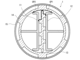
- FIG. 1 is a cross-sectional view of the power transmission device according to the first embodiment of the present disclosure.
- FIG. 2 is a perspective view of the power transmission device according to the first embodiment of the present disclosure.
- FIG. 3 is a perspective view of a conductor and a spacer according to the first embodiment of the present disclosure.
- FIG. 4 is a perspective view of a spacer according to the first embodiment of the present disclosure.
- FIG. 5 is a perspective view of a conduit according to the first embodiment of the present disclosure.
- the power transmission device 1 includes a first conductor 11, a second conductor 12, a first spacer 13, a second spacer 14, and a conduit 15.
- the power transmission device 1 is a device for transmitting DC power.
- the first conductor 11 and the second conductor 12 are electric wires that constitute the main line of the DC power circuit, and a positive voltage (positive pole) of DC power is applied to the first conductor 11, and a negative voltage (negative pole) of DC power is applied to the second conductor 12.
- the conductor is a material with a relatively high electrical conductivity, and can be made of, for example, copper, aluminum, or other metals.
- the first spacer 13 is an insulator that separates the first conductor 11 and the second conductor 12.
- an insulator is an object through which electric current flows very little.
- the second spacer 14 is an insulator that has a hollow portion 141 and contains the first conductor 11, the second conductor 12, and the first spacer 13 in the hollow portion 141.
- the second spacer 14 separates the first conductor 11 and the second conductor 12 from the electric conduit 15.
- the electric conduit 15 is a conductor that contains the second spacer 14.
- the electric conduit 15 is formed of a metal such as aluminum.
- the electric conduit 15 can also be referred to as a metal conduit.
- a fluid 16, such as air at atmospheric pressure, a pressurized gas, or a pressurized fluid such as liquid, is introduced into the electric conduit 15.
- the fluid 16 forms an insulating layer and functions as a cooling medium for air-cooling or water-cooling the first conductor 11, the second conductor 12, etc.
- the electric conduit 15 can be grounded, for example.
- the first conductor 11 and the second conductor 12 and the first spacer 13, the first conductor 11 and the second conductor 12 and the second spacer 14, and the second spacer 14 and the electric conduit 15 are assembled in contact or with a certain gap allowed, and are not fixed to each other. However, each component may be fixed as appropriate.
- the contact state or gap between the first conductor 11 and the second conductor 12 and the first spacer 13, between the first conductor 11 and the second conductor 12 and the second spacer 14, and between the second spacer 14 and the electric conduit 15 change depending on, for example, the temperature state and the magnitude of the repulsive force acting between the first conductor 11 and the second conductor 12 due to the electromagnetic force, etc.
- the first spacer 13 has a first surface 131 facing the first conductor 11 and a second surface 132 facing the second conductor 12, the first surface 131 having a plurality of first convex portions 133 and a plurality of first concave portions 134, and the second surface 132 having a plurality of second convex portions 135 and a plurality of second concave portions 136.
- each first concave portion 134 is arranged so as to include each position PA where each line LA connecting each contact point 137 between the second conductor 12 and each second convex portion 135 and the first conductor 11 in the shortest distance passes through the first surface 131.
- each second concave portion 136 is arranged so as to include each position PB where each line LB connecting each contact point 138 between the first conductor 11 and each first convex portion 133 and the second conductor 12 in the shortest distance passes through the second surface 132.
- an insulating material layer made of the first spacer 13 and a fluid layer such as an air layer made of a fluid such as air 16 are always arranged in series between the portions of the first conductor 11 and the second conductor 12 where a potential difference occurs. Therefore, with this configuration, even if dielectric breakdown occurs in the fluid layer, the dielectric breakdown can be prevented by the insulating material layer, so that the occurrence of dielectric breakdown between the first conductor 11 and the second conductor 12 can be suppressed.
- the second spacer 14 also has a third surface 142 facing the conduit 15, as shown in Figs. 4 and 6.
- the third surface 142 also has a number of third recesses 143.
- each of the third recesses 143 is arranged so as to include each position PC where each line LC that connects the fourth surface 144 of the second spacer 14 forming the hollow portion 141 with each contact point 145 of the first conductor 11 or the second conductor 12 and the conduit 15 in the shortest distance passes through the third surface 142.
- an insulating layer made of the second spacer 14 and a fluid layer such as an air layer made of a fluid such as air 16 are always arranged in series between the first conductor 11 and the second conductor 12 and the conduit 15 where a potential difference occurs. Therefore, with this configuration, even if dielectric breakdown occurs in the fluid layer, the dielectric breakdown can be prevented by the insulating layer, so that the occurrence of dielectric breakdown between the first conductor 11 and the second conductor 12 and the conduit 15 can be suppressed.
- the first conductor 11 and the second conductor 12 have a first plate-shaped portion B1 that faces the first spacer 13 and extends in the direction of DC power transmission, and one or more second plate-shaped portions B2 that extend toward the fourth surface 144 from the first plate-shaped portion B1 as a base end B11.
- the one or more second plate-shaped portions B2 also include a plate-shaped portion B21 that extends vertically from the plate surface B12 of the first plate-shaped portion B1.
- FIG. 7 is a perspective view of another example of the first spacer 13 (first spacer 13a) according to the first embodiment of the present disclosure.
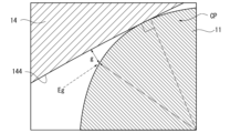
- Figure 8 is a partially enlarged cross-sectional view of the spacer and conductor according to the first embodiment of the present disclosure.
- Figure 9 is a diagram showing an example of the relationship between the gap length g between the conductor and spacer according to the first embodiment of the present disclosure and the gap electric field Eg (double logarithmic scale).
- Figures 10 and 11 are diagrams showing examples of the creepage distance between the conductors according to the first embodiment of the present disclosure.
- Figure 8 shows a partially enlarged contact portion between the first conductor 11 and the second spacer 14.
- the first conductor 11 and the second conductor 12 have a curved shape at the portion CP that contacts the fourth surface 144.
- the curved shape of the portion CP was set by performing a simulation using the finite element method or the like to determine the relationship between the gap length g and the gap electric field Eg shown in Figure 9 so as to avoid the discharge region.
- the shapes of the first conductor 11, the second conductor 12, and the first spacer 13 are set so that the necessary creepage distances can be secured for the creepage distance CP1 of the first spacer 13 between the first conductor 11 and the second conductor 12, and the creepage distance CP2 of the second spacer 14 between the first conductor 11 and the second conductor 12.
- a fluid layer such as an air layer and an insulating material layer are arranged in series between the first conductor 11 and the second conductor 12 where a potential difference occurs, and between the first conductor 11 and the second conductor 12 and the electric conduit 15, so that the occurrence of dielectric breakdown can be suppressed.
- the shape of the conductor and insulating material is adopted such that the creepage distance of the insulating material where a high voltage occurs is equal to or greater than the insulation distance, so that the resistance to insulation can be improved.
- the round-trip current path is placed inside a metal tube, making it easier to reduce weight compared to when the outbound and return paths are configured using separate cables. Also, because the positive and negative conductors face each other, the Coulomb force can be increased to suppress radiation, thereby reducing electromagnetic radiation.
- the cooling margin is greatly improved by selecting a high heat resistant material for the insulating material in contact with the transmission line (conductor).
- the material can be selected according to the concept under conditions that are established in terms of electric field, cooling, and strength. For example, multiple specifications that can be adopted are prepared so that the conductor material can be aluminum if weight is emphasized, and copper can be selected if transmission efficiency is emphasized.
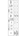
- FIG. 12 shows an example of setting material specifications.
- the upper limit of the heat generation temperature of the transmission line is raised, so that the cooling flow rate (flow velocity) can be reduced and a realistic solution can be obtained.
- a high heat resistant material such as fluororesin
- the cooling flow rate flow velocity
- copper or aluminum as the material of the transmission line, it can be reflected in the design that emphasizes weight (lightweight: aluminum) and efficiency (low loss: copper).
- Figs. 13 to 15 are schematic diagrams showing a configuration example of a power transmission system according to a third embodiment of the present disclosure.
- the aircraft 20 shown in Fig. 13 is an electric aircraft in which electric power generated by a generator 22 driven by an aircraft engine 21 is transmitted as DC power via a transmission line 102 to drive a boundary layer suction (BLI (Boundary Layer Ingestion)) fan 23 provided at the rear.
- the transmission line 102 is configured using a plurality of the power transmission devices 1 of the first embodiment. However, the transmission line 102 may be configured by one power transmission device 1.
- the power transmission system 100 includes a generator 22, a converter (AC/DC power conversion device) 101 that receives AC power generated by the generator 22, converts it to DC power and outputs it to the power transmission device 1, a transmission line 102, and an inverter (AC/DC power conversion device) 103 that receives DC power from the power transmission device 1, converts it to AC power and outputs it.
- a converter AC/DC power conversion device
- AC/DC power conversion device AC/DC power conversion device
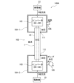
- power transmission system 100A in FIG. 14 includes a transmission line 102 (one or more power transmission devices 1), a converter 101 housed in a first housing 104-1, an inverter 103 housed in a second housing 104-2, a pressurizing unit 105 such as a pump that introduces pressurized fluid such as air into the transmission line 102, the first housing 104-1, and the second housing 104-2, and an exhaust unit 106 that exhausts the pressurized fluid from the transmission line 102, the first housing 104-1, and the second housing 104-2 while maintaining the pressurized state.
- a transmission line 102 one or more power transmission devices 1
- a converter 101 housed in a first housing 104-1
- an inverter 103 housed in a second housing 104-2
- a pressurizing unit 105 such as a pump that introduces pressurized fluid such as air into the transmission line 102, the first housing 104-1, and the second housing 104-2
- an exhaust unit 106 that exhausts the pressurized
- the electric conduit 15 of the power transmission device 1 and the first and second housings 104-1 and 104-2 are electrically connected by a connection unit 111, and are sealed so that the power transmission device 1, the first housing 104-1, and the second housing 104-2 form a pressurized space together.
- the pressurizing unit 105 includes a pressurizing unit 105-1 that introduces pressurized fluid into the power transmission device 1, a pressurizing unit 105-2 that introduces pressurized fluid into the first housing 104-1, and a pressurizing unit 105-3 that introduces pressurized fluid into the second housing 104-2.
- the exhaust unit 106 includes an exhaust unit 106-1 that exhausts the pressurized fluid from the power transfer device 1, an exhaust unit 106-2 that exhausts the pressurized fluid from the first housing 104-1, and an exhaust unit 106-3 that exhausts the pressurized fluid from the second housing 104-2.
- the power transmission path between the power transfer device 1 and the first and second housings 104-1 and 104-2 passes through a non-pressurized area, so power is transmitted using, for example, a thick, insulated wire CW.
- the breakdown voltage of a fluid layer such as air can be increased by applying pressure, making it possible to suppress the occurrence of dielectric breakdown in the transmission line 102, converter 101, and inverter 103.
- a conduit 15 metal conduit with low resistance is made to function as a current return path (return line for power transmission).
- the conduit 15 is electrically connected to also function as a current return path in the airframe structure, and the number of current return paths is significantly reduced.
- lightning current can be passed by connecting both ends of the conduit 15 to the airframe, and the effect of significantly reducing the number of current return paths made of copper wires required for the airframe structure can be obtained.
- the metal conduit resistance of the electric conduit 15 ( ⁇ 120 mm, thickness 2.5 mm, is about 3 u ⁇ /m for aluminum, and even if a total lightning current of 200 kA flows through a 10 m metal conduit, the voltage generated at both ends will be about 6 V (3E-6 x 200E3), and the impact on the system is tolerable.
- the power transmission system 100C shown in FIG. 16 is a case of a monopole conductor return type power transmission system
- the power transmission system 100D shown in FIG. 17 is a case of a bipole neutral conductor type power transmission system.
- the embodiment of the present disclosure has been described above in detail with reference to the drawings, the specific configuration is not limited to this embodiment, and design changes and the like within the scope of the present disclosure are also included.
- the shapes of the first conductor 11 and the second conductor 12 are not limited to those described above.
- the number of second plate-shaped portions B2 is not limited to three, and may be two or less, or four or more.
- the second plate-shaped portion B2 may have a shape extending radially from the first plate-shaped portion B1, for example.
- the power transfer device 1 and the power transfer system 100 described in each embodiment can be understood, for example, as follows.
- the power transmission device 1 comprises a first conductor 11 to which a positive voltage of DC power is applied, a second conductor 12 to which a negative voltage of the DC power is applied, a first spacer 13 made of an insulator separating the first conductor 11 and the second conductor 12, a second spacer 14 made of an insulator having a hollow portion 141 and containing the first conductor 11, the second conductor 12, and the first spacer 13 in the hollow portion 141, and a conduit 15 made of a conductor containing the second spacer 14, wherein the first spacer 13 has a first surface 131 facing the first conductor 11 and a second surface 132 facing the second conductor 12,
- the first surface 131 has a plurality of first convex portions 133 and a plurality of first concave portions 134
- the second surface 132 has a plurality of second convex portions 135 and a plurality of second concave portions 136, and each of the first concave portions 134 is arranged so that each line LA connecting
- the power transmission device 1 according to the second aspect is the power transmission device 1 according to (1), in which the second spacer 14 has a third surface 142 facing the electric conduit 15, and the third surface 142 has a plurality of third recesses 143, and each of the third recesses 143 is arranged so as to include each position PC where each line LC that connects the fourth surface 144 of the second spacer forming the hollow portion 141 and each contact point 145 between the first conductor 11 or the second conductor 12 and the electric conduit 15 in the shortest distance passes through the third surface 142.
- the power transmission device 1 according to the third aspect is the power transmission device 1 according to (1) or (2), in which the first conductor 11 and the second conductor 12 have a first plate-shaped portion B1 that faces the first spacer 13 and extends in the direction of transmission of DC power, and one or more second plate-shaped portions B2 that extend in the direction of the fourth surface 144 with the first plate-shaped portion B1 as a base end B11.
- the power transmission device 1 according to the fourth aspect is the power transmission device 1 according to (3), in which one or more of the second plate-shaped portions B2 include a plate-shaped portion B21 extending vertically from the plate surface B12 of the first plate-shaped portion B1.
- the power transmission device 1 according to the fifth aspect is the power transmission device 1 according to (2) to (4), in which the first conductor 11 and the second conductor 12 have a curved shape (part CP) at the portion in contact with the fourth surface 144.
- the power transmission device 1 according to the sixth aspect is the power transmission device 1 according to any one of (1) to (5), in which a pressurized fluid is introduced into the electric conduit 15.
- the seventh aspect of the power transmission device 1 is the power transmission device 1 of (1) to (6), which is mounted on an aircraft and in which the conduit 15 is connected to the return line of the power transmission.
- the power transmission system 100 (100A and 100B) according to the eighth aspect includes one or more power transmission devices 1 of (1) to (7), an AC/DC power conversion device (converter 101) housed in a first housing 104-1 that receives AC power, converts it to DC power, and outputs it to the power transmission device, an AC/DC power conversion device (inverter 103) housed in a second housing 104-2 that receives DC power from the power transmission device, converts it to AC power, and outputs it, a pressurizing unit that introduces pressurized fluid into the one or more power transmission devices, the first housing, and the second housing, and an exhaust unit that exhausts the pressurized fluid from the one or more power transmission devices, the first housing, and the second housing.
- an AC/DC power conversion device (converter 101) housed in a first housing 104-1 that receives AC power, converts it to DC power, and outputs it to the power transmission device
- an AC/DC power conversion device inverter 103 housed in a second housing 104
- the power transmission system 100A according to the ninth aspect is the power transmission system 100A according to (8), in which one or more of the power transmission devices, the first housing, and the second housing integrally form a pressurized space.
- the power transmission device and power transmission system disclosed herein can suppress the occurrence of dielectric breakdown.
- REFERENCE SIGNS LIST 1 power transmission device 100
- power transmission system 11 first conductor 12
- second conductor 13 first spacer 14
- electric conduit 16 electric conduit
Landscapes
- Engineering & Computer Science (AREA)
- Aviation & Aerospace Engineering (AREA)
- Gas-Insulated Switchgears (AREA)
Abstract
電力伝送装置は、直流電力の正電圧が印加される第1導体と、直流電力の負電圧が印加される第2導体と、第1導体と第2導体とを離隔する絶縁体の第1スペーサと、第2スペーサと、電線管とを備え、第1スペーサは、第1導体に対向する複数の第1凸部と複数の第1凹部とを有する第1面と、第2導体に対向する複数の第2凸部と複数の第2凹部とを有する第2面とを有し、各第1凹部は、第2導体と各第2凸部との各接触点と第1導体とを最短距離で結ぶ各線が第1面を貫く各位置を包含するよう配置され、各第2凹部は、第1導体と各第1凸部との各接触点と第2導体とを最短距離で結ぶ各線が第2面を貫く各位置を包含するよう配置されている。
Description
本開示は、電力伝送装置および電力伝送システムに関する。本願は、2023年12月28日に、日本に出願された特願2023-222687号に基づき優先権を主張し、その内容をここに援用する。
特許文献1および2には、電力伝送用のケーブルの構成例が示されている。特許文献1および2に記載されているケーブルは、中空の内部を画定する導体と、導体を取り囲むケーシングと、導体とケーシングとの間に配置される電気絶縁体と、導体の中空内部に配置された流体とを備える。この構成において、導体とケーシングとの間に配置される電気絶縁体は、加圧流体、固体等である。
しかしながら、特許文献1および2に記載のケーブルでは、電気絶縁体を加圧流体とした場合、高高度条件において例えばケーシングからのリークによって加圧状態が維持できなくなった場合、絶縁破壊が発生するおそれがあるという課題がある。
本開示は、上記課題を解決するためになされたものであって、絶縁破壊の発生を抑制することがきる電力伝送装置および電力伝送システムを提供することを目的とする。
上記課題を解決するために、本開示に係る電力伝送装置は、直流電力の正電圧が印加される第1導体と、前記直流電力の負電圧が印加される第2導体と、前記第1導体と前記第2導体とを離隔する絶縁体の第1スペーサと、中空部を有し、前記第1導体と前記第2導体と前記第1スペーサとを前記中空部に包蔵する絶縁体の第2スペーサと、前記第2スペーサを包蔵する導体の電線管とを備え、前記第1スペーサは、前記第1導体に対向する第1面と、前記第2導体に対向する第2面とを有し、前記第1面は複数の第1凸部と複数の第1凹部とを有し、前記第2面は複数の第2凸部と複数の第2凹部とを有し、各前記第1凹部は、前記第2導体と各前記第2凸部との各接触点と前記第1導体とを最短距離で結ぶ各線が前記第1面を貫く各位置を包含するよう配置され、各前記第2凹部は、前記第1導体と各前記第1凸部との各接触点と前記第2導体とを最短距離で結ぶ各線が前記第2面を貫く各位置を包含するよう配置されている。
本開示に係る電力伝送システムは、1または複数の上記電力伝送装置と、第1筐体に収納され、交流電力を入力し直流電力に変換して前記電力伝送装置へ出力する交直電力変換装置と、第2筐体に収納され、前記電力伝送装置から直流電力を入力し交流電力に変換して出力する直交電力変換装置と、1または複数の前記電力伝送装置と前記第1筐体と前記第2筐体内へ加圧流体を導入する加圧部と、1または複数の前記電力伝送装置と前記第1筐体と前記第2筐体から加圧流体を排気する排気部と、を備える。
本開示の電力伝送装置および電力伝送システムによれば、絶縁破壊の発生を抑制することができる。
<第1実施形態>
図1~図11を参照して、本開示の第1実施形態に係る電力伝送装置について説明する。図1は、本開示の第1実施形態に係る電力伝送装置の断面図である。図2は、本開示の第1実施形態に係る電力伝送装置の斜視図である。図3は、本開示の第1実施形態に係る導体およびスペーサの斜視図である。図4は、本開示の第1実施形態に係るスペーサの斜視図である。図5は、本開示の第1実施形態に係る電線管の斜視図である。なお、各図において同一または対応する構成には同一の符号を用いて説明を適宜省略する。また、本明細書で使用される「第1」、「第2」、「第3」、および「第4」という文言は、ある構成要素を別の構成要素と区別するために交換可能に使用される。
図1~図11を参照して、本開示の第1実施形態に係る電力伝送装置について説明する。図1は、本開示の第1実施形態に係る電力伝送装置の断面図である。図2は、本開示の第1実施形態に係る電力伝送装置の斜視図である。図3は、本開示の第1実施形態に係る導体およびスペーサの斜視図である。図4は、本開示の第1実施形態に係るスペーサの斜視図である。図5は、本開示の第1実施形態に係る電線管の斜視図である。なお、各図において同一または対応する構成には同一の符号を用いて説明を適宜省略する。また、本明細書で使用される「第1」、「第2」、「第3」、および「第4」という文言は、ある構成要素を別の構成要素と区別するために交換可能に使用される。
図1~図5に示すように、本開示の第1実施形態に係る電力伝送装置1は、第1導体11と、第2導体12と、第1スペーサ13と、第2スペーサ14と、電線管15とを備える。電力伝送装置1は、直流電力を伝送するための装置である。
第1導体11と第2導体12とは、直流電力の電路の本線を構成する電線であり、第1導体11には直流電力の正電圧(正極)が印加され、第2導体12には直流電力の負電圧(負極)が印加される。なお、本実施形態において、導体とは、電気の伝導率が比較的大きな物質であり、例えば、銅、アルミニウム、その他の金属等で構成することができる。
第1スペーサ13は、第1導体11と第2導体12とを離隔する絶縁体である。本実施形態において、絶縁体とは、電流が極めて流れにくい物体である。第2スペーサ14は、中空部141を有し、第1導体11と第2導体12と第1スペーサ13とを中空部141に包蔵する絶縁体である。第2スペーサ14は、第1導体11および第2導体12と電線管15とを離隔する。電線管15は、第2スペーサ14を包蔵する導体である。電線管15は、例えばアルミニウム等の金属で形成される。電線管15は、金属コンジット(conduit)等ともいうことができる。電線管15内には、大気圧の空気等の流体、加圧された気体、液体等の加圧流体等の流体16が導入されている。流体16は、絶縁層を形成するとともに、第1導体11、第2導体12等を空冷または水冷する冷却媒体として機能する。また、電線管15は例えば接地することができる。
なお、第1導体11および第2導体12と第1スペーサ13間、第1導体11および第2導体12と第2スペーサ14間、第2スペーサ14と電線管15間は、接触または一定の間隙を許容した状態で組み合わされており、互いに固定されてはない。ただし、各構成間は適宜固定してもよい。例えば、第1導体11および第2導体12と第1スペーサ13間、第1導体11および第2導体12と第2スペーサ14間、第2スペーサ14と電線管15間の接触状態や間隙は、例えば温度状態や第1導体11および第2導体12間に電磁力によって働く斥力の大きさ等によって変化する。
第1スペーサ13は、第1導体11に対向する第1面131と、第2導体12に対向する第2面132とを有し、第1面131は複数の第1凸部133と複数の第1凹部134とを有し、第2面132は複数の第2凸部135と複数の第2凹部136とを有する。図6に示すように、各第1凹部134は、第2導体12と各第2凸部135との各接触点137と第1導体11とを最短距離で結ぶ各線LAが第1面131を貫く各位置PAを包含するよう配置されている。また、各第2凹部136は、第1導体11と各第1凸部133との各接触点138と第2導体12とを最短距離で結ぶ各線LBが第2面132を貫く各位置PBを包含するよう配置されている。
この構成によれば、電位差が発生する第1導体11と第2導体12の部位間には、第1スペーサ13による絶縁材層と、空気等の流体16による空気層等の流体層が必ず直列に配置されることなる。このため、この構成によれば、流体層の絶縁破壊が発生したとしても、絶縁材層によって絶縁破壊を阻止することができるため、第1導体11と第2導体12との間の絶縁破壊の発生を抑制することがきる。
また、第2スペーサ14は、図4および図6に示すように、電線管15に対向する第3面142を有する。また、第3面142は複数の第3凹部143を有する。また、各第3凹部143は、図6に示すように、中空部141を形成する第2スペーサ14の第4面144と第1導体11または第2導体12との各接触点145と電線管15とを最短距離で結ぶ各線LCが第3面142を貫く各位置PCを包含するように配置されている。
この構成によれば、電位差が発生する第1導体11および第2導体12と電線管15の部位間には、第2スペーサ14による絶縁材層と、空気等の流体16による空気層等の流体層が必ず直列に配置されることなる。このため、この構成によれば、流体層の絶縁破壊が発生したとしても、絶縁材層によって絶縁破壊を阻止することができるため、第1導体11および第2導体12と電線管15の間の絶縁破壊の発生を抑制することがきる。
また、本実施形態では、第1導体11および第2導体12は、図1に示すように、第1スペーサ13に対向し、直流電力の伝送方向に延在する第1板状部B1と、第1板状部B1を基端部B11として第4面144方向へ伸長する1または複数の第2板状部B2とを備える。また、1または複数の第2板状部B2は、第1板状部B1の板面B12から垂直方向に延びる板状部B21を含む。この構成によれば、冷却効率の向上(表面積の増大、抵抗値の減少等)と軽量化とをバランスよく獲得することができる。
なお、第1スペーサ13および第2スペーサ14の形状は上記のものに限定されず、例えば図7に示す第1スペーサ13aのように、第1凸部133、第1凹部134、第2凸部135および第2凹部136は、直流電力の伝送方向に対して不連続であってもよい。図7は、本開示の第1実施形態に係る第1スペーサ13の他の例(第1スペーサ13a)の斜視図である。
次に、図8~図11を参照して、各部の形状等の設定例について説明する。図8は、本開示の第1実施形態に係るスペーサと導体の一部拡大断面図である。図9は、本開示の第1実施形態に係る導体とスペーサ間のギャップ長gとギャップ電界Egとの関係(両対数目盛)の一例を示す図である。図10および図11は、本開示の第1実施形態に係る導体間の沿面距離の例を示す図である。図8は、第1導体11と、第2スペーサ14との接触部を一部拡大して示す。第1導体11および第2導体12については、第4面144と接触する部分CPに曲面形状を有している。部分CPの曲面形状は、有限要素法等によるシミュレーションを実施し、図9に示すギャップ長gとギャップ電界Egとの関係を求め、放電領域を回避できるように設定した。また、図10および図11に示すように第1導体11と第2導体12間の第1スペーサ13の沿面距離CP1と、第1導体11と第2導体12間の第2スペーサ14の沿面距離CP2については、必要な沿面距離を確保できるように、第1導体11と第2導体12と第1スペーサ13の形状を設定した。
以上のように本実施形態によれば、電位差が発生する第1導体11と第2導体12との間、ならびに、第1導体11および第2導体12と電線管15との間に、空気層等の流体層と、絶縁材層とが直列して配置されるようにしたので、絶縁破壊の発生を抑制することがきる。また、高電圧が発生する絶縁材沿面距離を絶縁距離以上とする導体および絶縁材の形状を採用したので、絶縁に対する耐性を向上させることができた。
また、本実施形態では、往復電流路を金属管内に入れているので、往路と復路を別のケーブルを用いて構成する場合と比較して、軽量化しやすい。また、正負の導体が対向しているため、クーロン力を高めて放射抑制を図ることができ、電磁放射を低減することができる。
<第2実施形態>
次に第2実施形態としてコンセプトに応じた材料選定について説明する。本実施形態においては、伝送路(導体)に接する絶縁材に高耐熱材を選定することで冷却裕度を大幅に向上させている。また、電界、冷却、強度面で成立する条件にてコンセプトに応じて材料を選択できるようにしている。例えば、重量重視なら導体の材料をアルミとし、伝送効率重視なら銅を選択できるように採用可能な仕様を複数用意した。図12は、材料の仕様の設定例を示す。絶縁材にフッ素樹脂等の高耐熱材を使うことで、伝送路の発熱温度の上限が上がるため、冷却流量(流速)を下げることができ、現実解を得ることができる。また、伝送路の材料として銅もしくはアルミを選択することで、重量重視(軽量:アルミ)、効率重視(低損失:銅)の設計に反映できることを確認した。
次に第2実施形態としてコンセプトに応じた材料選定について説明する。本実施形態においては、伝送路(導体)に接する絶縁材に高耐熱材を選定することで冷却裕度を大幅に向上させている。また、電界、冷却、強度面で成立する条件にてコンセプトに応じて材料を選択できるようにしている。例えば、重量重視なら導体の材料をアルミとし、伝送効率重視なら銅を選択できるように採用可能な仕様を複数用意した。図12は、材料の仕様の設定例を示す。絶縁材にフッ素樹脂等の高耐熱材を使うことで、伝送路の発熱温度の上限が上がるため、冷却流量(流速)を下げることができ、現実解を得ることができる。また、伝送路の材料として銅もしくはアルミを選択することで、重量重視(軽量:アルミ)、効率重視(低損失:銅)の設計に反映できることを確認した。
<第3実施形態>
次に、図13~図15を参照して、第1実施形態の電力伝送装置1を、航空機に適用する場合を第3実施形態として説明する。図13~図15は、本開示の第3実施形態に係る電力伝送システムの構成例を示す模式図である。図13に示す航空機20は、航空用エンジン21によって駆動される発電機22で発電した電力を伝送路102によって直流送電し、後部に設けられた境界層吸い込み(BLI(Boundary Layer Ingestion))ファン23を駆動する電動航空機である。伝送路102は、第1実施形態の電力伝送装置1を複数用いて構成されている。ただし、伝送路102は1つの電力伝送装置1で構成されていてもよい。電力伝送システム100は、発電機22と、発電機22が発電した交流電力を入力し直流電力に変換して電力伝送装置1へ出力するコンバータ(交直電力変換装置)101と、伝送路102と、電力伝送装置1から直流電力を入力し交流電力に変換して出力するインバータ(直交電力変換装置)103とを備える。
次に、図13~図15を参照して、第1実施形態の電力伝送装置1を、航空機に適用する場合を第3実施形態として説明する。図13~図15は、本開示の第3実施形態に係る電力伝送システムの構成例を示す模式図である。図13に示す航空機20は、航空用エンジン21によって駆動される発電機22で発電した電力を伝送路102によって直流送電し、後部に設けられた境界層吸い込み(BLI(Boundary Layer Ingestion))ファン23を駆動する電動航空機である。伝送路102は、第1実施形態の電力伝送装置1を複数用いて構成されている。ただし、伝送路102は1つの電力伝送装置1で構成されていてもよい。電力伝送システム100は、発電機22と、発電機22が発電した交流電力を入力し直流電力に変換して電力伝送装置1へ出力するコンバータ(交直電力変換装置)101と、伝送路102と、電力伝送装置1から直流電力を入力し交流電力に変換して出力するインバータ(直交電力変換装置)103とを備える。
図13に示す電力伝送システム100は、例えば図14に電力伝送システム100Aとして示すように、伝送路102(1または複数の電力伝送装置1)と、第1筐体104-1に収納されたコンバータ101と、第2筐体104-2に収納されたインバータ103と、伝送路102と第1筐体104-1と第2筐体104-2との中へ空気等を加圧した加圧流体を導入するポンプ等の加圧部105と、伝送路102と第1筐体104-1と第2筐体104-2とから加圧状態を保持した状態で加圧流体を排気する排気部106と、を備える。電力伝送装置1の電線管15と、第1筐体104-1および第2筐体104-2とは、接続部111によって、電気的に接続されるとともに、電力伝送装置1と第1筐体104-1と第2筐体104-2とが一体的に加圧空間を形成するように密閉されている。
図15は、図13に示す電力伝送システム100の他の構成例を電力伝送システム100Bとして示す。図15に示す電力伝送システム100Bでは、伝送路102(電力伝送装置1)と第1筐体104-1と第2筐体104-2とが個々に加圧空間を形成する。電力伝送装置1の電線管15にはフランジ112-1および112-2が両端部に設けられ、電線管15とフランジ112-1および112-2によって密閉空間を形成する。この場合、加圧部105は、電力伝送装置1内へ加圧流体を導入する加圧部105-1と、第1筐体104-1内へ加圧流体を導入する加圧部105-2と、第2筐体104-2内へ加圧流体を導入する加圧部105-3とを含む。また、排気部106は、電力伝送装置1から加圧流体を排気する排気部106-1と、第1筐体104-1から加圧流体を排気する排気部106-2と、第2筐体104-2から加圧流体を排気する排気部106-3とを含む。また、電力伝送装置1と、第1筐体104-1および第2筐体104-2との間の電力伝送路は非予圧領域を通過するので例えば絶縁性を有する厚い皮膜電線CWを利用して電力を伝送する。
本実施形態によれば、空気等の流体層の破壊電圧を加圧によって高くすることができるので、伝送路102と、コンバータ101と、インバータ103における絶縁破壊の発生を抑制することがきる。
<第4実施形態>
次に、第4実施形態について図16および図17を参照して説明する。本実施形態では、抵抗が小さい電線管15(金属コンジット)を電流リターン路(電力送電の帰線)として機能させる。図16および図17に示す電力伝送システム100Cおよび100Dでは、電線管15を機体構造における電流リターン路を兼ねる電気接続とし、電流リターン路の本数を大幅減少させる。本実施形態によれば、例えば、電線管15の両端を機体に接続することで雷電流を流すことができ、機体構造として必要となる銅線による電流リターン路の本数を大幅に減らせる効果が得られる。例えば、電線管15の金属コンジット抵抗(Φ120mm、厚み2.5mm、アルミでは3uΩ/m程度であり、10mの金属コンジットに全雷電流200kAが流れたとしても両端に発生する電圧は6V程度(3E-6×200E3)となり、システムへの影響は許容できる。なお、図16に示す電力伝送システム100Cは、単極導体帰路方式の送電方式の場合であり、図17に示す電力伝送システム100Dは、双極中性線導体方式の送電方式の場合である。
次に、第4実施形態について図16および図17を参照して説明する。本実施形態では、抵抗が小さい電線管15(金属コンジット)を電流リターン路(電力送電の帰線)として機能させる。図16および図17に示す電力伝送システム100Cおよび100Dでは、電線管15を機体構造における電流リターン路を兼ねる電気接続とし、電流リターン路の本数を大幅減少させる。本実施形態によれば、例えば、電線管15の両端を機体に接続することで雷電流を流すことができ、機体構造として必要となる銅線による電流リターン路の本数を大幅に減らせる効果が得られる。例えば、電線管15の金属コンジット抵抗(Φ120mm、厚み2.5mm、アルミでは3uΩ/m程度であり、10mの金属コンジットに全雷電流200kAが流れたとしても両端に発生する電圧は6V程度(3E-6×200E3)となり、システムへの影響は許容できる。なお、図16に示す電力伝送システム100Cは、単極導体帰路方式の送電方式の場合であり、図17に示す電力伝送システム100Dは、双極中性線導体方式の送電方式の場合である。
(その他の実施形態)
以上、本開示の実施の形態について図面を参照して詳述したが、具体的な構成はこの実施の形態に限られるものではなく、本開示の要旨を逸脱しない範囲の設計変更等も含まれる。例えば、第1導体11および第2導体12の形状は上記のものに限定されない。例えば、第2板状部B2は3枚に限らず、2枚以下または4枚以上であってもよい。また、第2板状部B2は、例えば、第1板状部B1から放射状に伸びる形状を有していてもよい。
以上、本開示の実施の形態について図面を参照して詳述したが、具体的な構成はこの実施の形態に限られるものではなく、本開示の要旨を逸脱しない範囲の設計変更等も含まれる。例えば、第1導体11および第2導体12の形状は上記のものに限定されない。例えば、第2板状部B2は3枚に限らず、2枚以下または4枚以上であってもよい。また、第2板状部B2は、例えば、第1板状部B1から放射状に伸びる形状を有していてもよい。
<付記>
各実施形態に記載の電力伝送装置1および電力伝送システム100は、例えば以下のように把握される。
各実施形態に記載の電力伝送装置1および電力伝送システム100は、例えば以下のように把握される。
(1)第1の態様に係る電力伝送装置1は、直流電力の正電圧が印加される第1導体11と、前記直流電力の負電圧が印加される第2導体12と、前記第1導体11と前記第2導体12とを離隔する絶縁体の第1スペーサ13と、中空部141を有し、前記第1導体11と前記第2導体12と前記第1スペーサ13とを前記中空部141に包蔵する絶縁体の第2スペーサ14と、前記第2スペーサ14を包蔵する導体の電線管15とを備え、前記第1スペーサ13は、前記第1導体11に対向する第1面131と、前記第2導体12に対向する第2面132とを有し、前記第1面131は複数の第1凸部133と複数の第1凹部134とを有し、前記第2面132は複数の第2凸部135と複数の第2凹部136とを有し、各前記第1凹部134は、前記第2導体12と各前記第2凸部135との各接触点137と前記第1導体11とを最短距離で結ぶ各線LAが前記第1面131を貫く各位置PAを包含するよう配置され、各前記第2凹部136は、前記第1導体11と各前記第1凸部133との各接触点138と前記第2導体12とを最短距離で結ぶ各線LBが前記第2面132を貫く各位置PBを包含するよう配置されている。本態様および以下の各態様によれば、絶縁破壊の発生を抑制することがきる。
(2)第2の態様に係る電力伝送装置1は、(1)の電力伝送装置1であって、前記第2スペーサ14は、前記電線管15に対向する第3面142を有し、前記第3面142は複数の第3凹部143を有し、各前記第3凹部143は、前記中空部141を形成する前記第2スペーサの第4面144と前記第1導体11または前記第2導体12との各接触点145と前記電線管15とを最短距離で結ぶ各線LCが前記第3面142を貫く各位置PCを包含するように配置されている。
(3)第3の態様に係る電力伝送装置1は、(1)または(2)の電力伝送装置1であって、前記第1導体11および前記第2導体12は、前記第1スペーサ13に対向し、直流電力の伝送方向に延在する第1板状部B1と、前記第1板状部B1を基端部B11として前記第4面144方向へ伸長する1または複数の第2板状部B2とを備える。
(4)第4の態様に係る電力伝送装置1は、(3)の電力伝送装置1であって、1または複数の前記第2板状部B2は、前記第1板状部B1の板面B12から垂直方向に延びる板状部B21を含む。
(5)第5の態様に係る電力伝送装置1は、(2)~(4)の電力伝送装置1であって、前記第1導体11および前記第2導体12は、前記第4面144と接触する部分に曲面形状(部分CP)を有している。
(6)第6の態様に係る電力伝送装置1は、(1)~(5)の電力伝送装置1であって、前記電線管15内に加圧流体が導入されている。
(7)第7の態様に係る電力伝送装置1は、(1)~(6)の電力伝送装置1であって、航空機に搭載されていて、前記電線管15が電力送電の帰線に接続されている。
(8)第8の態様に係る電力伝送システム100(100Aおよび100B)は、1または複数の(1)~(7)の電力伝送装置1と、第1筐体104-1に収納され、交流電力を入力し直流電力に変換して前記電力伝送装置へ出力する交直電力変換装置(コンバータ101)と、第2筐体104-2に収納され、前記電力伝送装置から直流電力を入力し交流電力に変換して出力する直交電力変換装置(インバータ103)と、1または複数の前記電力伝送装置と前記第1筐体と前記第2筐体内へ加圧流体を導入する加圧部と、1または複数の前記電力伝送装置と前記第1筐体と前記第2筐体から加圧流体を排気する排気部と、を備える。
(9)第9の態様に係る電力伝送システム100Aは、(8)の電力伝送システム100Aであって、1または複数の前記電力伝送装置と前記第1筐体と前記第2筐体とが加圧空間を一体的に形成する。
本開示の電力伝送装置および電力伝送システムによれば、絶縁破壊の発生を抑制することができる。
1…電力伝送装置
100…電力伝送システム
11…第1導体
12…第2導体
13…第1スペーサ
14…第2スペーサ
15…電線管
16…流体
100…電力伝送システム
11…第1導体
12…第2導体
13…第1スペーサ
14…第2スペーサ
15…電線管
16…流体
Claims (9)
- 直流電力の正電圧が印加される第1導体と、
前記直流電力の負電圧が印加される第2導体と、
前記第1導体と前記第2導体とを離隔する絶縁体の第1スペーサと、
中空部を有し、前記第1導体と前記第2導体と前記第1スペーサとを前記中空部に包蔵する絶縁体の第2スペーサと、
前記第2スペーサを包蔵する導体の電線管と、
を備え、
前記第1スペーサは、前記第1導体に対向する第1面と、前記第2導体に対向する第2面とを有し、
前記第1面は複数の第1凸部と複数の第1凹部とを有し、
前記第2面は複数の第2凸部と複数の第2凹部とを有し、
各前記第1凹部は、前記第2導体と各前記第2凸部との各接触点と前記第1導体とを最短距離で結ぶ各線が前記第1面を貫く各位置を包含するよう配置され、
各前記第2凹部は、前記第1導体と各前記第1凸部との各接触点と前記第2導体とを最短距離で結ぶ各線が前記第2面を貫く各位置を包含するよう配置されている、
電力伝送装置。 - 前記第2スペーサは、前記電線管に対向する第3面を有し、
前記第3面は複数の第3凹部を有し、
各前記第3凹部は、前記中空部を形成する前記第2スペーサの第4面と前記第1導体または前記第2導体との各接触点と前記電線管とを最短距離で結ぶ各線が前記第3面を貫く各位置を包含するように配置されている、
請求項1に記載の電力伝送装置。 - 前記第1導体および前記第2導体は、前記第1スペーサに対向し、直流電力の伝送方向に延在する第1板状部と、前記第1板状部を基端部として前記第4面方向へ伸長する1または複数の第2板状部と、
を備える請求項2に記載の電力伝送装置。 - 1または複数の前記第2板状部は、前記第1板状部の板面から垂直方向に延びる板状部を含む、
請求項3に記載の電力伝送装置。 - 前記第1導体および前記第2導体は、前記第4面と接触する部分に曲面形状を有している、
請求項4に記載の電力伝送装置。 - 前記電線管内に加圧流体が導入されている、
請求項5に記載の電力伝送装置。 - 航空機に搭載されていて、
前記電線管が電力送電の帰線に接続されている、
請求項1から6のいずれか1項に記載の電力伝送装置。 - 1または複数の請求項1に記載の電力伝送装置と、
第1筐体に収納され、交流電力を入力し直流電力に変換して前記電力伝送装置へ出力する交直電力変換装置と、
第2筐体に収納され、前記電力伝送装置から直流電力を入力し交流電力に変換して出力する直交電力変換装置と、
1または複数の前記電力伝送装置と前記第1筐体と前記第2筐体内へ加圧流体を導入する加圧部と、
1または複数の前記電力伝送装置と前記第1筐体と前記第2筐体から加圧流体を排気する排気部と、
を備える電力伝送システム。 - 1または複数の前記電力伝送装置と前記第1筐体と前記第2筐体とが加圧空間を一体的に形成する、
請求項8に記載の電力伝送システム。
Applications Claiming Priority (2)
| Application Number | Priority Date | Filing Date | Title |
|---|---|---|---|
| JP2023222687A JP2025104697A (ja) | 2023-12-28 | 2023-12-28 | 電力伝送装置および電力伝送システム |
| JP2023-222687 | 2023-12-28 |
Publications (1)
| Publication Number | Publication Date |
|---|---|
| WO2025142121A1 true WO2025142121A1 (ja) | 2025-07-03 |
Family
ID=96218932
Family Applications (1)
| Application Number | Title | Priority Date | Filing Date |
|---|---|---|---|
| PCT/JP2024/039110 Pending WO2025142121A1 (ja) | 2023-12-28 | 2024-11-01 | 電力伝送装置および電力伝送システム |
Country Status (2)
| Country | Link |
|---|---|
| JP (1) | JP2025104697A (ja) |
| WO (1) | WO2025142121A1 (ja) |
Citations (3)
| Publication number | Priority date | Publication date | Assignee | Title |
|---|---|---|---|---|
| JPS54107079U (ja) * | 1978-01-13 | 1979-07-27 | ||
| JP2007049813A (ja) * | 2005-08-09 | 2007-02-22 | Chugoku Electric Power Co Inc:The | 管路の内部スペーサー及び管路の内部スペーサーの先導具 |
| CN214279669U (zh) * | 2021-03-22 | 2021-09-24 | 山东聚辰电缆有限公司 | 一种风能发电设备用电力电缆 |
-
2023
- 2023-12-28 JP JP2023222687A patent/JP2025104697A/ja active Pending
-
2024
- 2024-11-01 WO PCT/JP2024/039110 patent/WO2025142121A1/ja active Pending
Patent Citations (3)
| Publication number | Priority date | Publication date | Assignee | Title |
|---|---|---|---|---|
| JPS54107079U (ja) * | 1978-01-13 | 1979-07-27 | ||
| JP2007049813A (ja) * | 2005-08-09 | 2007-02-22 | Chugoku Electric Power Co Inc:The | 管路の内部スペーサー及び管路の内部スペーサーの先導具 |
| CN214279669U (zh) * | 2021-03-22 | 2021-09-24 | 山东聚辰电缆有限公司 | 一种风能发电设备用电力电缆 |
Also Published As
| Publication number | Publication date |
|---|---|
| JP2025104697A (ja) | 2025-07-10 |
Similar Documents
| Publication | Publication Date | Title |
|---|---|---|
| CN211127444U (zh) | 一种集成化电驱系统 | |
| US11451118B2 (en) | Conductor arrangement and transportable electrical drive device | |
| US9490555B1 (en) | System or connector for voltage bus structures | |
| JP2025104697A (ja) | 電力伝送装置および電力伝送システム | |
| US11783987B2 (en) | Transformer and power module including the same | |
| US3325588A (en) | Removable bus conductor connector | |
| US12348011B2 (en) | Sinusoidal tubular conducting busbar | |
| EP1774541B1 (en) | Flexible high temperature cables | |
| CN105720785A (zh) | 一种单管多段液态金属磁流体发电机 | |
| CN103112413B (zh) | 用于并行配线电路的可扩展连接系统 | |
| SE531321C2 (sv) | Högspänningskabelanslutning | |
| WO2022221996A1 (en) | Bus-duct and associated manufacturing method | |
| CN110199371A (zh) | 具有改善的散热的继电器组件以及具有所述继电器组件的变换器装置 | |
| US10615098B2 (en) | Dielectric heat path devices, and systems and methods using the same | |
| WO2025134561A1 (ja) | 電力伝送システム、部分放電検出方法および電力伝送装置 | |
| US12401180B2 (en) | Electric power device and moving object with electric power device | |
| CN218919921U (zh) | 一种紧凑密集型母线槽 | |
| CN223274426U (zh) | 一种高压控制器和电机 | |
| JP7566213B1 (ja) | ガス絶縁開閉装置 | |
| CN223347713U (zh) | 一种断路器 | |
| EP4636345A1 (en) | Thermal and mechanical management device and system comprising such a device | |
| CN213304928U (zh) | 一种全屏蔽型母线槽 | |
| CN222301432U (zh) | 一种组合电器和柔直系统启动回路 | |
| EP4636788A1 (en) | Electrically insulated heat and mechanical link, system comprising such an electrically insulated heat and mechanical link, and a method for manufacturing such an electrically insulated heat and mechanical link | |
| CN120915152A (zh) | 航空高压直流发电机构型可变式输出整流装置 |
Legal Events
| Date | Code | Title | Description |
|---|---|---|---|
| 121 | Ep: the epo has been informed by wipo that ep was designated in this application |
Ref document number: 24912014 Country of ref document: EP Kind code of ref document: A1 |