WO2025141908A1 - 作業車両 - Google Patents
作業車両 Download PDFInfo
- Publication number
- WO2025141908A1 WO2025141908A1 PCT/JP2024/022576 JP2024022576W WO2025141908A1 WO 2025141908 A1 WO2025141908 A1 WO 2025141908A1 JP 2024022576 W JP2024022576 W JP 2024022576W WO 2025141908 A1 WO2025141908 A1 WO 2025141908A1
- Authority
- WO
- WIPO (PCT)
- Prior art keywords
- power
- vehicle body
- harvesting device
- output shaft
- traveling
- Prior art date
- Legal status (The legal status is an assumption and is not a legal conclusion. Google has not performed a legal analysis and makes no representation as to the accuracy of the status listed.)
- Pending
Links
Images



























Classifications
-
- A—HUMAN NECESSITIES
- A01—AGRICULTURE; FORESTRY; ANIMAL HUSBANDRY; HUNTING; TRAPPING; FISHING
- A01B—SOIL WORKING IN AGRICULTURE OR FORESTRY; PARTS, DETAILS, OR ACCESSORIES OF AGRICULTURAL MACHINES OR IMPLEMENTS, IN GENERAL
- A01B71/00—Construction or arrangement of setting or adjusting mechanisms, of implement or tool drive or of power take-off; Means for protecting parts against dust, or the like; Adapting machine elements to or for agricultural purposes
- A01B71/02—Setting or adjusting mechanisms
-
- B—PERFORMING OPERATIONS; TRANSPORTING
- B62—LAND VEHICLES FOR TRAVELLING OTHERWISE THAN ON RAILS
- B62D—MOTOR VEHICLES; TRAILERS
- B62D49/00—Tractors
-
- B—PERFORMING OPERATIONS; TRANSPORTING
- B62—LAND VEHICLES FOR TRAVELLING OTHERWISE THAN ON RAILS
- B62D—MOTOR VEHICLES; TRAILERS
- B62D49/00—Tractors
- B62D49/06—Tractors adapted for multi-purpose use
Definitions
- the present invention relates to a work vehicle for performing work such as agricultural work.
- Patent Document 1 A work vehicle disclosed in the following Patent Document 1 is known in the prior art.
- the work vehicle (tractor) disclosed in Patent Document 1 comprises a running body, a power unit (engine) mounted on the running body, an output shaft (PTO shaft) for extracting power generated by the power unit to the rear, and a mounting section (three-point linkage mechanism) for mounting a work implement (cultivator) to the rear of the running body.
- the above-mentioned work vehicle can output the power generated by the power unit from the output shaft to the rear of the traveling body and transmit it to the work equipment attached to the mounting part.
- the power generated by the power unit cannot be output above the traveling body and transmitted to the work equipment.
- the present invention was made in consideration of the above problems, and aims to provide a work vehicle that can output the power generated by the power unit above the running body and transmit it to the work equipment.
- a work vehicle comprises a running body, a power unit mounted on the running body, a mounting section that can mount a work device having a power input section to which power is input onto the running body and that allows at least the power input section to be mounted onto the running body, and a power transmission mechanism that outputs the power generated by the power unit above the running body so that it can be transmitted to the work device.
- the power transmission mechanism may have an upward output shaft that extends upward and outputs the power generated by the power unit above the traveling body.
- It may be equipped with a lateral output shaft that outputs the power generated by the power unit forward, backward, or to the side, and the upward output shaft may branch off from the middle of the lateral output shaft and extend upward.
- the work vehicle may be equipped with a lateral output shaft that outputs the power generated by the power unit forward, backward, or to the side, and the power transmission mechanism may have a change mechanism that allows the lateral output shaft to be changed to an upward direction that extends upward.
- the change mechanism may include a lifting device that raises and lowers a second working device located in front or behind the traveling body, and the lifting device may change the lateral output shaft to an upward direction when the second working device is not attached.
- the work vehicle may be equipped with a lateral output shaft that outputs the power generated by the power unit forward, backward, or to the side, and the power transmission mechanism may have a gear transmission mechanism that extracts power from a mid-way point of the lateral output shaft and outputs it above the traveling body.
- the work vehicle may be equipped with a lateral output shaft that outputs the power generated by the power unit forward, backward, or to the side, and the power transmission mechanism may have a belt transmission mechanism that extracts power from a mid-way portion of the lateral output shaft and outputs it above the traveling body.
- the working device may have a downward input shaft connected to the upward output shaft as the power input section.
- the working device may have, as the power input section, a downward input shaft that is connected to the lateral output shaft that has been changed to face upward.
- the gear transmission mechanism may have an output gear that outputs the power taken from the middle of the horizontal output shaft to above the traveling body, and the working device may have an input gear that meshes with the output gear as the power input section.
- the work vehicle includes a running body, a power unit mounted on the running body, a working device having a power input unit to which power is input, a mounting unit that allows the working device to be mounted on the running body and at least the power input unit to be mounted on the running body, and a power transmission mechanism that outputs the power generated by the power unit above the running body so that it can be transmitted to the working device.
- the work system motor 6 may be a hydraulic motor.
- the hydraulic motor is driven by hydraulic oil supplied from a hydraulic pump.
- the hydraulic pump is driven by the travel system motor 5, the hydraulic motor (work system motor 6) is driven by the hydraulic oil supplied from the hydraulic pump, and the external output shaft is driven by the drive of the hydraulic motor.
- the work vehicle 1 may be equipped with a work system motor 6 that is a hydraulic motor in addition to the work system motor 6 that is an electric motor.
- the wheels 30 are arranged on the sides of the vehicle body 2.
- the left front wheel 3LF and the left rear wheel 3LB are arranged on the left side of the vehicle body 2.
- the right front wheel 3RF and the right rear wheel 3RB are arranged on the right side of the vehicle body 2.
- the size (diameter and width) of the rear wheels (left rear wheel 3LB, right rear wheel 3RB) is larger than the size (diameter and width) of the front wheels (left front wheel 3LF, right front wheel 3RF).
- the work vehicle 1 is equipped with a lifting device 10 that can be raised and lowered by mounting a work device 300 different from the work device 200 described below.
- the different work device 300 will be referred to as the "second work device 300" below.
- the second work device 300 can be detachably mounted to the lifting device 10.
- the lifting device 10 is provided at the rear of the vehicle body 2.
- Figure 5 is a view of the lifting device 10 as seen from the rear.
- the lifting device 10 may also be provided at the front or side (left or right) of the vehicle body 2.
- the type of the second work device 300 attached to the lifting device 10 is not particularly limited.
- the second work device 300 may be a device for performing agricultural work (farm work), a device for performing civil engineering work, a device for performing construction work, a device for performing transportation work, etc.
- the lifting device 10 is composed of a three-point link mechanism. Specifically, as shown in FIG. 5, the lifting device 10 has a lift arm 10a, a lower link 10b, a top link 10c, a lift rod 10d, and a lift cylinder 10e.
- the front end of the lift arm 10a is supported on the upper rear part of the vehicle body 2 so that it can swing upward or downward.
- the lift arm 10a swings (lifts and lowers) when driven by the lift cylinder 10e.
- the lift cylinder 10e is composed of a hydraulic cylinder.
- the lift cylinder 10e is connected to a hydraulic pump (not shown) via a control valve (not shown).
- the hydraulic pump is driven by the work system motor 6.
- the control valve is an electromagnetic valve or the like whose flow path is controlled to open and close by the control device 15.
- the flow of hydraulic oil discharged from the hydraulic pump can be controlled by the control valve to extend and retract the lift cylinder 10e.
- the front end of the lower link 10b is supported on the rear lower part of the vehicle body 2 so that it can swing upward or downward.
- the front end of the top link 10c is supported on the rear part of the vehicle body 2 above the lower link 10b so that it can swing upward or downward.
- the lift rod 10d connects the lift arm 10a to the lower link 10b.
- the second work device 300 is connected to the rear part of the lower link 10b and the rear part of the top link 10c. When the lift cylinder 10e is driven (extends and retracts), the lift arm 10a rises and lowers, and the lower link 10b connected to the lift arm 10a via the lift rod 10d rises and lowers. As a result, the second work device 300 swings upward or downward (rises and falls) with the front part of the lower link 10b as a fulcrum.
- the second work device 300 attached to the lifting device 10 is towed by the work vehicle 1 as the work vehicle 1 travels.
- a cart or the like for transporting agricultural products or the like may be attached to the lifting device 10.
- the work vehicle 1 is equipped with a positioning device 11.
- the positioning device 11 can detect the position of the vehicle body 2 (positioning information including latitude and longitude) using a satellite positioning system (positioning satellite) such as D-GPS, GPS, GLONASS, Hokuto, Galileo, and Michibiki.
- a satellite positioning system positioning satellite
- the positioning device 11 receives satellite signals transmitted from the positioning satellites (position of the positioning satellite, transmission time, correction information, etc.), and detects the position of the vehicle body 2 (e.g., latitude, longitude) based on the satellite signals.
- the positioning device 11 has a receiving device 12 and an inertial measurement unit (IMU) 13.
- the receiving device 12 has an antenna and the like and is a device that receives satellite signals transmitted from positioning satellites, and is attached to the vehicle body 2.
- the inertial measurement unit 13 has an acceleration sensor that detects acceleration, a gyro sensor that detects angular velocity, and the like.
- the inertial measurement unit 13 is attached to the vehicle body 2.
- the inertial measurement unit 13 can detect the roll angle, pitch angle, yaw angle, etc. of the vehicle body 2.
- the yaw angle may be detected by installing multiple positioning devices 11.
- the work vehicle 1 is equipped with a communication device 14.
- the communication device 14 includes a communication circuit for communicating via an in-vehicle network and a wireless communication circuit for wireless communication.
- the wireless communication circuit can directly or indirectly wirelessly communicate with an external device using the IEEE 802.11 series of communication standards such as Wi-Fi (Wireless Fidelity, registered trademark), BLE (Bluetooth (registered trademark) Low Energy), LPWA (Low Power, Wide Area), and LPWAN (Low-Power Wide-Area Network).
- the communication device 14 may be provided with a communication circuit capable of wirelessly communicating with an external device, for example, via a mobile phone communication network or a data communication network.
- the external device may be, for example, a personal computer, a smartphone, a tablet computer, a PDA, or a server.
- the external device may include, for example, an operation device 80, which will be described later.
- the work vehicle 1 is equipped with a control device 15.
- the control device 15 is mounted on the traveling body 100.
- the control device 15 is a device that performs various controls of the work vehicle 1.
- the control device 15 is equipped with a calculation unit (CPU, etc.) and a memory unit (RAM, ROM, etc.).
- the memory unit may include an external memory provided outside the control device 15.
- the control device 15 is connected to the various devices and mechanisms shown in FIG. 7 via an in-vehicle LAN (on-board network) such as a CAN (Controller Area Network) or a communication line.
- LAN on-board network
- CAN Controller Area Network
- the control device 15 controls the operation of various devices and mechanisms communicatively connected to the control device 15 by the calculation unit executing various control programs stored in the memory unit.
- the functions of each control unit of the control device 15 (automatic driving control unit 15A, height change control unit 15B) described below are realized by the calculation unit executing predetermined control programs stored in the memory unit.
- the control device 15 includes an automatic driving control unit 15A.
- the automatic driving control unit 15A controls the automatic driving of the traveling machine body 100.
- the traveling machine body 100 is equipped with a control device 15 that performs automatic driving.
- the automatic driving control unit 15A can execute line-type automatic driving control and autonomous-type automatic driving control.
- line-type automatic driving control the automatic driving control unit 15A controls the operation of the steering mechanism 60, the transmission 9, the motor 5, etc., which will be described later, so that the traveling machine body 100 (vehicle body 2) moves along a predetermined planned driving line.
- the automatic driving control unit 15A sets the direction of travel (steering direction) and vehicle speed (vehicle speed) of the vehicle body 2 based on the results of sensing (detecting objects) around the traveling body 100 (vehicle body 2) using the positioning device 11, etc., and controls the operation of the steering mechanism 60, transmission 9, motor 5, etc. to achieve the set steering and vehicle speed.
- the automatic driving control unit 15A may be configured to be able to execute either the line-type automatic driving control or the autonomous automatic driving control.
- the configuration of the automatic driving control unit 15A is not limited to the configuration described above.
- the control device 15 of the traveling body 100 includes an automatic driving control unit 15A, so that the work vehicle 1 can perform automatic driving (unmanned driving) without an operator on board. Therefore, the traveling body 100 of the illustrated embodiment does not have a driver's seat where an operator sits.
- the work vehicle 1 may be a vehicle that an operator rides in and performs automatic driving.
- the work vehicle 1 may be a vehicle that an operator rides in and drives to perform driving.
- a driver's seat is provided in the vehicle body 2.
- the work vehicle 1 is equipped with a lighting device 16.
- the lighting device 16 is provided on the vehicle body 2.
- the lighting device 16 includes at least a headlight that illuminates the area in front of the vehicle body 2.
- the lighting device 16 may include a plurality of work lights that illuminate the area around the vehicle body 2.
- the work lights can, for example, illuminate the sides (left and right) of the vehicle body 2 or the rear of the vehicle body 2.
- the lighting device 16 may also include status indicator lights, left and right lights, brake lights, etc.
- the work vehicle 1 is equipped with an alarm device 17.
- the alarm device 17 alerts people around the vehicle body 2 of danger (approaching vehicle body 2, etc.) by sound, light, etc.
- the alarm device 17 is composed of a speaker, warning light, etc.
- the right frame 18R is provided on the right side of the vehicle body 2.
- the right frame 18R extends in the up-down direction along the vehicle body 2.
- the right frame 18R also extends in the front-rear direction along the vehicle body 2.
- the right frame 18R connects the right front wheel 3RF and the right rear wheel 3RB.
- the first connector 21R3 connects the first front support 21R1 and the first rear support 21R2.
- the first connector 21R3 is composed of frame material 21AR, frame material 21BR, frame material 21CR, frame material 21DR, and frame material 21ER.
- Frame material 21AR extends in the front-to-rear direction and connects the upper part of the first front support 21R1 to the upper part of the first rear support 21R2.
- Frame material 21BR extends in the front-to-rear direction to the right of frame material 21AR.
- Frame material 21CR connects the front part of frame material 21AR to the front part of frame material 21BR.
- Frame material 21DR connects the rear part of frame material 21AR to the rear part of frame material 21BR.
- Frame material 21ER connects the midpoint of frame material 21AR in the fore-and-aft direction to the midpoint of frame material 21BR in the fore-and-aft direction.
- the configuration of the frame structure 18 is not limited to the configuration shown in the figure.
- the frame structure 18 may include a connection frame that connects the second left frame 20L and the second right frame 22R.
- the connection frame can connect, for example, the upper part of the second left frame 20L and the upper part of the second right frame 22R.
- the connection frame also becomes the movable frame 32.
- the drive unit 40 includes a first drive unit 41 for driving the left front wheel 3LF, a second drive unit 42 for driving the right front wheel 3RF, a third drive unit 43 for driving the left rear wheel 3LB, and a fourth drive unit 44 for driving the right rear wheel 3RB.
- the first drive unit 41, the second drive unit 42, the third drive unit 43, and the fourth drive unit 44 each have a drive device 45 and a transmission mechanism 50 described below.
- the first drive unit 41 and the second drive unit 42 each have a steering mechanism 60 described below.
- Each drive unit is attached to the frame structure 18.
- the third drive unit 43 has a motor 5LB and a transmission mechanism 50LB that transmits the power of the motor 5LB to the left rear wheel 3LB.
- the transmission mechanism 50LB is composed of a gear mechanism including multiple gears.
- the fourth drive unit 44 has a motor 5RB and a transmission mechanism 50RB that transmits the power of the motor 5RB to the right rear wheel 3RB.
- the transmission mechanism 50RB is composed of a gear mechanism including multiple gears.
- the drive unit 40 has a steering mechanism 60 that changes the direction of the wheels 30.
- the steering mechanism 60 is a mechanism that changes the direction of the front wheels (left front wheel 3LF and right front wheel 3RF) among the wheels 30.
- the steering mechanism 60 includes a left steering mechanism 60L that changes the direction of the left front wheel 3LF, and a right steering mechanism 60R that changes the direction of the right front wheel 3RF.
- the first drive unit 41 is equipped with a left steering mechanism 60L.
- the second drive unit 42 is equipped with a right steering mechanism 60R.
- the left steering mechanism 60L can rotate the left front wheel 3LF around the axis AX1 by driving the cylinder 62 to extend and retract the rod 62a.
- the right steering mechanism 60R can rotate the right front wheel 3RF around the axis AX2 by driving the cylinder 62 to extend and retract the rod 62a.
- the traveling direction of the traveling body 100 can be changed by driving the steering mechanism 60 to change the orientation of the left front wheel 3LF and the right front wheel 3RF.
- the motor of the drive device 45 may be an in-wheel motor.
- all of the left front wheel 3LF, right front wheel 3RF, left rear wheel 3LB, and right rear wheel 3RB may be driven by the in-wheel motor, or only some of the wheels (for example, the left front wheel 3LF and the right front wheel 3RF, or the left rear wheel 3LB and the right rear wheel 3RB) may be driven by the in-wheel motor.
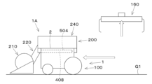
- the crops cut by the cutting device of the harvesting section 210 are transported by the conveyor of the transport section 220, passing through the inside of the cylindrical body 221 and moving diagonally upward from the front (or rear) of the lower part of the traveling body 100 to above the traveling body 100.
- the storage section 230 stores the crops transported by the transport section 220.
- the storage section 230 is composed of, for example, a grain tank.
- the storage section 230 stores the crops transported by the transport section 220 and passed through the threshing section 240.
- the threshing section 240 is located above the traveling body 100 and on the left side of the harvesting device 200 (the left side of the harvester 1A).
- the rear part of the tubular body 221 is connected to the threshing section 240.
- the crops transported through the inside of the tubular body 221 are supplied to the threshing section 240 for threshing processing.
- a discharge section 250 is provided that cuts and discharges the straw generated by the threshing process.
- the discharge section 250 is located at the rear of the harvesting device 200 (the rear of the harvester 1A).
- the storage section 230 stores the grains that have been threshed and sorted by the threshing section 240.
- the storage section 230 is located above the traveling body 100 and on the right side of the harvesting device 200 (the right side of the harvester 1A).
- the discharge section 260 is connected to the storage section 230.
- the discharge section 260 can discharge the crops (grains) stored in the storage section 230 to the outside by driving an auger or the like. When the storage section (grain tank) 230 becomes full, the crops (grains) stored in the storage section 230 are discharged by the discharge section 260.
- the harvesting device 200 is equipped with a base plate 270 that supports each component part (harvesting section 210, conveying section 220, storage section 230, threshing section 240, release section 250, discharge section 260) that has a harvesting function.
- the harvesting section 210 is arranged below the base plate 270 (below and in front of the base plate 270). More specifically, the harvesting section 210 is arranged below and in front of the base plate 270.
- the front part of the conveying section 220 is arranged below the base plate 270. More specifically, the front part of the conveying section 220 is arranged below and in front of the base plate 270.
- the rear part of the conveying section 220 is arranged above the base plate 270.
- the threshing section 240 and storage section 230 are fixed onto the base plate 270.
- the substrate 270 is, for example, a plate that is approximately rectangular in plan view. In the example shown in FIG. 16, the substrate 270 has a rectangular shape with a portion cut out. The shape, size, and thickness of the substrate 270 can be changed as appropriate depending on the shape, size, weight, etc. of the components of the harvesting device 200 (the storage section 230, the threshing section 240) that are fixed onto the substrate 270.
- the shape, size, and thickness of the substrate 270 can also be changed depending on the mounting structure (described later) of the harvesting device 200 to the traveling body 100. For example, when recesses 501, insertion holes 503, protrusions 504, grooves 505, etc., described later, are provided on the substrate 270, the thickness of the substrate 270 can be increased as necessary.
- the mounting unit 400 allows at least the power input unit 280 of the harvesting device 200 to be mounted on the traveling body 100. Therefore, the harvesting device 200 is mounted so that at least the power input unit 280 is disposed on the traveling body 100. This allows the harvesting device 200 to receive power from the traveling body 100 on the traveling body 100.
- the harvesting device 200 is mounted so that at least a portion of the drive unit (such as the threshing unit 240) that is driven by the power input from the power input unit 280 is disposed on the traveling body 100 (above the vehicle body 2).
- the harvesting device 200 is disposed so that at least a portion of the harvesting unit 210 is located below the upper end of the vehicle body 2 (near the ground).
- the harvesting device 200 is constructed separately from the running body 100, and can be attached and detached to the running body 100. As described above, the harvesting device 200 can be made smaller and lighter, which makes it easier to attach and detach the harvesting device 200 to the running body 100.
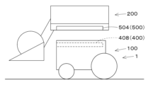
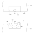
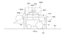
- Figure 17 shows a first example of the mounting structure of the harvesting device 200 to the traveling body 100.
- the attachment/detachment mechanism 400 has a convex portion 401 that protrudes upward from the top surface of the traveling body 100 (top surface of the vehicle body 2).
- the top of the vehicle body 2 is provided with a convex portion 401 that protrudes upward.
- the convex portion 401 is configured to be able to rise and fall. Specifically, the convex portion 401 rises and falls by raising and lowering the vehicle body 2.
- the convex portion 401 has a first tapered surface 402 that is inclined so that the width of the convex portion 401 narrows toward the top.
- the first tapered surface 402 is inclined so that the width of the convex portion 401 in the front-to-back and left-to-right directions narrows toward the top.
- the convex portion 401 is conical or frustum-shaped
- the first tapered surface 402 is composed of one curved surface.
- the convex portion 401 is pyramidal or frustum-shaped
- the first tapered surface 402 is composed of multiple flat surfaces. For example, if the convex portion 401 is quadrangular pyramidal or frustum-shaped, the first tapered surface 402 is composed of four flat surfaces (front, rear, left, and right).
- the convex portion 401 is provided as a single protuberance that covers the entire or nearly entire surface of the top surface of the vehicle body 2.
- the convex portion 401 is provided as a protuberance that covers the entire or nearly entire surface of the top surface of the vehicle body 2.
- the convex portion 401 may be a protuberance provided at multiple locations on the top surface of the vehicle body 2.
- the recess 501 can be formed, for example, in the substrate 270 of the harvesting device 200 (see Figures 11 to 14 and 16). In this case, the thickness of the substrate 270 is set to a sufficient thickness to form the recess 501. However, the recess 501 may also be formed on the underside of a part of the harvesting device 200 other than the substrate 270.
- the recess 501 has a second tapered surface 502.
- the second tapered surface 502 has a shape corresponding to the first tapered surface 402 of the protrusion 401.
- the second tapered surface 502 abuts (comes into surface contact with) the first tapered surface 402 when the harvesting device (working device) 200 is attached to the vehicle body 2.
- the first tapered surface 402 is preferably provided over the entire convex portion 401 (from the upper end to the lower end), but it is sufficient that it is provided at least on the upper portion including the upper end of the convex portion 401 (from the upper end to the middle in the vertical direction).
- the second tapered surface 502 is preferably provided over the entire concave portion 501 (from the lower end to the upper end), but it is sufficient that it is provided at least on the upper portion including the upper end of the concave portion 501 (from the upper end to the middle in the vertical direction).
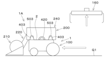
- Figure 18 shows a second example of the mounting structure of the harvesting device 200 to the traveling body 100.
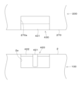
- the attachment/detachment mechanism 400 has a protrusion 403 that protrudes upward from the upper part of the traveling body 100.
- the protrusion 403 protrudes upward from the upper part of the vehicle body 2.
- the protrusion 403 protrudes upward from multiple points on the top surface of the vehicle body 2.
- the protrusion 403 can be provided near each of the four corners of the top surface of the vehicle body 2.
- the number and positions of the protrusions 403 can be changed as appropriate depending on the type and size of the harvesting device 200.
- the protrusion 403 is, for example, a rod-shaped (cylindrical, conical, truncated conical, etc.) pin.
- the protrusion 403 may be fixed to the upper surface of the traveling body 100 (the upper surface of the vehicle body 2), or may be provided so as to be retractable from the upper surface of the traveling body 100 (the upper surface of the vehicle body 2).
- the pin 404 constituting the protrusion 403 is connected to an upward rod 406 of a cylinder device 405.
- the cylinder device 405 is, for example, a hydraulic cylinder that can be driven by hydraulic oil supplied from the above-mentioned hydraulic pump.
- the multiple (all) pins 404 that make up the protrusion 403 are erected on a single plate 407, and this plate 407 is connected to an upward rod 406 of a cylinder device 405.
- This allows the multiple pins 404 to move simultaneously with the plate 407 and appear and disappear by moving (expanding) the rod 406 in the vertical direction.
- a configuration in which multiple cylinder devices 405 are provided and the multiple pins 404 are individually connected to the rods 406 of the cylinder devices 405 may also be used.
- the detachable part 500 is composed of an insertion hole 503 provided on the lower part of the harvesting device 200.
- the shape of the insertion hole 503 corresponds to the shape of the protrusion 403 of the detachable mechanism 400.
- the number and positions of the insertion holes 503 correspond to the number and positions of the protrusions 403 of the detachable mechanism 400.
- the insertion holes 503 can be formed, for example, in the base plate 270 of the harvesting device 200.
- the insertion holes 503 are provided near each of the four corners of the upper surface of the vehicle body 2 (see FIG. 6).
- the number and positions of the insertion holes 503 can be changed according to the number and positions of the protrusions 403.
- the insertion holes 503 may also be formed in a part of the harvesting device 200 other than the base plate 270.
- the harvesting device 200 can be mounted on the top of the vehicle body 2 by inserting the protrusion 403 provided on the top of the vehicle body 2 into the insertion hole 503 provided on the bottom of the harvesting device 200.
- the harvesting device 200 can be detached from the top of the vehicle body 2 by removing the protrusion 403 from the insertion hole 503.
- the insertion hole 503 is placed above the protrusion 403, and then the vehicle body 2 is raised or the harvesting device 200 is lowered, so that the protrusion 403 can be inserted into the insertion hole 503.
- the vehicle body 2 is lowered or the harvesting device 200 is raised, so that the protrusion 403 can be removed from the insertion hole 503.
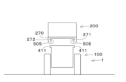
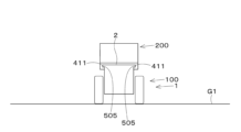
- the detachable portion 500 is composed of a groove 505 provided in the harvesting device 200.
- the groove 505 can be formed, for example, in the substrate 270.
- the substrate 270 is provided with a lower left portion 271 that protrudes downward from the left portion of the lower surface of the substrate 270 and extends in the front-rear direction, and a lower right portion 272 that protrudes downward from the right portion of the lower surface of the substrate 270 and extends in the front-rear direction.
- the groove 505 is formed on the inner surface (right surface) of the lower left portion 271 and the inner surface (left surface) of the lower right portion 272.
- the groove 505 may be formed in a portion of the harvesting device 200 other than the substrate 270.
- the upper and lower surfaces of the protrusion 411 are preferably tapered surfaces such that the vertical width of the protrusion 411 narrows toward the outer side of the protrusion 411 (the side facing the groove 505).
- the upper and lower surfaces of the groove 505 are preferably tapered surfaces such that the vertical width of the groove 505 widens toward the inner side of the groove 505 (the side facing the protrusion 411).
- the attachment/detachment mechanism 400 has a locking mechanism 420.
- the locking mechanism 420 is a mechanism that fixes the traveling machine body 100 and the harvesting device 200.
- the locking mechanism 420 is a mechanism that fixes the vehicle body 2 and the harvesting device 200.
- 24 and 25 are diagrams showing an example of the configuration of the locking mechanism 420 and the fixed part 430 fixed by the locking mechanism 420.
- the locking mechanism 420 is provided on the traveling machine body 100 (specifically, the vehicle body 2).
- the fixed part 430 is provided on the harvesting device 200.
- Figure 24 is a vertical cross-sectional view of the locking mechanism 420 and the fixed part 430 as viewed from the side.
- Figure 25 is a vertical cross-sectional view of the locking mechanism 420 and the fixed part 430 as viewed from the front. Hatching has been omitted from Figures 24 and 25 to simplify the drawings. Note that the illustrated locking mechanism 420 and fixed part 430 are merely an example, and the configuration of the locking mechanism 420 and fixed part 430 is not limited to this.
- the locking mechanism 420 is provided on the upper part of the vehicle body 2.
- the locking mechanism 420 has a locking member 421 that is arc-shaped in a side view, and a rotating shaft 422 that serves as the center of rotation of the locking member 421.
- a recess 2a is formed on the upper surface of the vehicle body 2, and the locking member 421 and the rotating shaft 422 are disposed within this recess 2a.
- the rotating shaft 422 extends in the left-right direction and rotates around an axis in the left-right direction.
- the rotating shaft 422 is directly or indirectly connected to the output shaft of a motor (not shown), and rotates when driven by the motor.
- the locking member 421 and the rotating shaft 422 are connected via a connecting part 423. As a result, the locking member 421 rotates around the rotating shaft 422 as the rotating shaft 422 rotates.
- the fixed part 430 is provided on the lower part of the base plate 270 of the harvesting device 200.
- the fixed part 430 has a fixed shaft 431 that extends in the left-right direction.
- a recess 270a is formed on the lower surface of the base plate 270, and the fixed shaft 431 is disposed within this recess 270a.
- the recess 2a formed on the upper surface of the vehicle body 2 and the recess 270a formed on the lower surface of the base plate 270 are positioned so that they overlap in the vertical direction when the harvesting device 200 is attached to the upper part of the vehicle body 2.
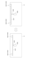
- Figure 26 shows the state when the locking mechanism 420 is not activated (left image) and the state after the locking mechanism 420 has been activated (right image).
- the engaging member 421 of the locking mechanism 420 is in the recess 2a of the vehicle body 2 and does not protrude from the top surface of the vehicle body 2. In this state, the engaging member 421 is not engaged with the fixed shaft 431 of the fixed part 430.
- the motor is driven to rotate the engaging member 421 together with the rotating shaft 422 (see arrow R1), and the engaging member 421 protrudes upward from the recess 2a of the vehicle body 2 and engages with the fixed shaft 431 in the recess 270a of the base plate 270. This fixes the traveling body 100 (specifically the vehicle body 2) and the harvesting device 200.
- the locking mechanism 420 fixes the traveling body 100 (specifically, the vehicle body 2) and the harvesting device 200 with the convex portion 401 provided on the vehicle body 2 inserted into the concave portion 501 provided on the harvesting device 200.
- the locking mechanism 420 fixes the traveling body 100 (specifically, the vehicle body 2) and the harvesting device 200 with the protrusion 403 provided on the vehicle body 2 inserted into the insertion hole 503 provided on the harvesting device 200.
- the locking mechanism 420 fixes the traveling body 100 (specifically, the vehicle body 2) and the harvesting device 200 with the protrusion 504 provided on the harvesting device 200 inserted into the groove portion 408 provided on the vehicle body 2.
- the locking mechanism 420 fixes the traveling body 100 (specifically the vehicle body 2) and the harvesting device 200 in a state in which the protrusion 411 on the vehicle body 2 is inserted into the groove 505 on the harvesting device 200.
- the locking mechanism 420 may be a mechanism for fixing the movable frame 32 attached to the vehicle body 2 and the harvesting device 200.
- the locking mechanism 420 is provided on the movable frame 32.
- the traveling body 100 and the harvesting device 200 are fixed by fixing the movable frame 32 and the harvesting device 200.
- the traveling body 100 can be provided with the convex portion 401 of the first example and the protruding portion 403 of the second example
- the harvesting device 200 can be provided with the concave portion 501 of the first example and the insertion hole 503 of the second example.
- the vehicle body 2 of the traveling machine body 100 is equipped with an attachment/detachment mechanism 400 that enables the working device (harvesting device) 200 to be attached and detached to the vehicle body 2.
- the attachment/detachment mechanism 400 has the locking mechanism 420 described above.
- the attachment/detachment mechanism 400 has a locking mechanism 420 that fixes the working device (harvesting device) 200 to the vehicle body 2 when the working device (harvesting device) 200 is placed on the vehicle body 2.
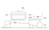
- Figures 27 to 47 show an example of a method of attaching the harvesting device 200 to the traveling body 100.
- a method of attaching the harvesting device 200 to the traveling body 100 will be explained based on Figures 27 to 47. Note that the traveling body 100 and the harvesting device 200 shown in Figures 27 to 47 are simplified versions of the traveling body 100 and the harvesting device 200 shown in Figures 1 to 5 and 10 to 14.
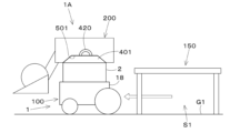
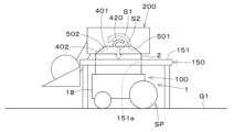
- Figures 27 to 31 show a first example of a method for mounting the harvesting device 200 to the traveling body 100.
- the first example mounting method is described below.
- the first example mounting method is used when the traveling body 100 and the harvesting device 200 have the mounting structure of the first example described above.
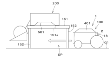
- the vehicle body 2 can be raised and lowered by the height change mechanism (lifting mechanism) 90 described above.
- the harvesting device 200 is held in a state where it is raised above the ground G1 (holding step). Specifically, the harvesting device 200 is placed on the stand 150, so that the harvesting device 200 is held in a state where it is raised above the ground G1.
- the mounting method of the first example described above can also be used when the traveling body 100 and the harvesting device 200 have the mounting structure of the second example.
- the mounting step the protrusion 403 provided on the vehicle body 2 is inserted into the insertion hole 503 provided on the harvesting device 200, and the locking mechanism 420 is operated with the protrusion 403 inserted into the insertion hole 503, thereby fixing the harvesting device 200 to the top of the vehicle body 2.
- the mounting method is the same as when the traveling body 100 and the harvesting device 200 have the mounting structure of the first example.
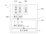
- the harvester 1A is configured so that power is supplied to the harvesting device 200 from a power unit 4 mounted on the traveling body 100 (see FIG. 48).
- the work vehicle 1 is equipped with a power transmission mechanism 600 capable of transmitting power generated from the power unit 4 to the harvesting device 200.
- the power transmission mechanism 600 outputs the power generated from the power unit 4 above the traveling body 100 so that it can be transmitted to the harvesting device 200.
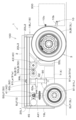
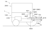
- Figure 50 is a diagram showing the work vehicle 1 equipped with the power transmission mechanism 600 of the first example, and the harvesting device 200 attached to the traveling machine body 100 of this work vehicle 1.
- the power transmission mechanism 600 of the first example has an upward output shaft 601 that extends upward and outputs the power generated by the power unit 4 above the traveling body 100.
- the upward output shaft 601 extends vertically or approximately vertically.
- the work vehicle 1 equipped with the power transmission mechanism 600 of the first example is equipped with, in addition to the upward output shaft 601, a lateral output shaft 602 that outputs the power generated by the power unit 4 rearward.
- the lateral output shaft 602 extends horizontally or approximately horizontally.
- the front end of the lateral output shaft 602 is connected to the work system motor 6 of the power unit 4.
- the rear end of the lateral output shaft 602 protrudes rearward from the vehicle body 2.
- the lateral output shaft 602 is capable of supplying power to a work device (second work device) attached to the lifting device 10 consisting of a three-point linkage mechanism.
- the upward output shaft 601 branches off from the middle of the horizontal output shaft 602 and extends upward. Specifically, a first bevel gear 603 is attached to the middle of the horizontal output shaft 602 in the extension direction (front-rear direction). A second bevel gear 604 that meshes with the first bevel gear 603 is attached to the lower end of the upward output shaft 601.
- the upward output shaft 601 branches off from the middle of the horizontal output shaft 602 as the first bevel gear 603 and the second bevel gear 604 mesh with each other.
- the upper end of the upward output shaft 601 is located near the upper end of the vehicle body 2.
- a shaft coupling 605 that can connect the shafts to each other is provided to the upper end of the upward output shaft 601.
- the power generated by the power unit 4 is transmitted to the horizontal output shaft 602, which rotates around its axis in the front-to-rear direction.
- the rotation of the horizontal output shaft 602 is transmitted from the first bevel gear 603 to the second bevel gear 604. This causes the upward output shaft 601 to rotate around its axis in the up-down direction.
- the harvesting device 200 mounted on the traveling body 100 of the work vehicle 1 equipped with the power transmission mechanism 600 of the first example has a power input unit 280 to which the power output from the power transmission mechanism 600 to the upper part of the traveling body 100 is input.
- the harvesting device 200 has a downward input shaft 281 connected to the upward output shaft 601 as the power input unit 280. The lower end of the downward input shaft 281 protrudes downward from the harvesting device 200.
- the upward output shaft 601 and the downward input shaft 281 are connected via a shaft coupling 605 (see Figure 51).
- the rotational power output from the upward output shaft 601 is input to the downward input shaft 281.
- the drive parts of the harvesting device 200 (harvesting section 210, conveying section 220, threshing section 240, discharge section 260, release section 250) are driven by the power input to the downward input shaft 281.
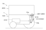
- the lifting device 10 changes the orientation of the lateral output shaft 602 to an upward orientation that extends upward.
- the lifting device 10 rises relative to the vehicle body 2, thereby changing the orientation of the lateral output shaft 602 to an upward orientation that extends upward.
- the lateral output shaft 602 is changed from a lateral orientation to an upward orientation as the lifting device 10 rises.
- the lateral output shaft 602 is changed from an upward orientation to a lateral orientation as the lifting device 10 descends.
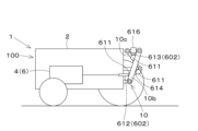
- the portion of the lateral output shaft 602 that protrudes from the traveling body 100 (vehicle body 2) (hereinafter referred to as the "protruding portion of the lateral output shaft 602") has a configuration in which multiple shafts are connected by joints 611.
- the joints 611 are configured to be bendable at least in the vertical direction.
- a universal joint that can bend in multiple directions is preferably used as the joints 611.
- the joints 611 will be described as being universal joints. However, the joints 611 are not limited to being universal joints.
- the multiple shafts include at least a first shaft 612 located on the base end side (vehicle body 2 side) of the protruding portion of the lateral output shaft 602, and a second shaft 613 located on the tip end side (opposite the vehicle body 2 side) of the protruding portion of the lateral output shaft 602.
- the number of shafts constituting the horizontal output shaft 602 may be two or three or more.
- the number of universal joints 611 can be increased according to the number of shafts constituting the horizontal output shaft 602.
- the horizontal output shaft 602 has four shafts connected by three universal joints 611.
- the horizontal output shaft 602 in the illustrated example has two more shafts (third shaft 614 and fourth shaft 615) between the first shaft 612 and second shaft 613 (see FIG. 52).
- the protruding portion of the horizontal output shaft 602 can bend at the universal joint 611. By bending the protruding portion of the horizontal output shaft 602 at the universal joint 611, the second shaft 613 can rotate upward relative to the first shaft 612.
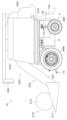
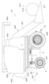
- the protruding portion of the horizontal output shaft 602 is connected to the lifting device 10. More specifically, the protruding portion of the horizontal output shaft 602 is connected to the lower link 10b and/or the top link 10c of the lifting device 10. In the example shown in FIG. 56, the protruding portion of the horizontal output shaft 602 is connected to the lower link 10b via a connecting member 617, and to the top link 10c via a connecting member 618. As a result, the protruding portion of the horizontal output shaft 602 rises and falls in conjunction with the rise and fall of the lifting device 10 (the rise and fall of the lower link 10b and the top link 10c). However, it is sufficient that the protruding portion of the horizontal output shaft 602 is connected to at least one of the lower link 10b and the top link 10c.
- the protruding portion of the horizontal output shaft 602 bends at the universal joint 611, and the second shaft 613 rotates upward or downward relative to the first shaft 612.
- the second shaft 613 rotates upward relative to the first shaft 612.
- the horizontal output shaft 602 (specifically, the second shaft 613) is changed to an upward orientation that extends upward (see Figure 53).
- the tip of the protruding portion of the horizontal output shaft 602 (the tip of the second shaft 613) is provided with a shaft coupling 616 that can connect the shafts together.
- a shaft coupling 616 that can connect the shafts together.
- the protruding portion of the horizontal output shaft 602 is disposed below the top link 10c of the lifting device 10 and above the lower link 10b (see FIG. 52, etc.).
- the protruding portion of the horizontal output shaft 602 is disposed at a position offset from the top link 10c in the left-right direction (see FIG. 56). This makes it possible to prevent the horizontal output shaft 602 from interfering with the top link 10c when the lower link 10b and the top link 10c are raised or lowered to change the orientation of the horizontal output shaft 602 (specifically, the second shaft 613) upward.
- top link 10c and/or the lower link 10b may also be configured with multiple members connected by a bendable joint (universal joint) in the same manner as the horizontal output shaft 602. This allows the top link 10c and/or the lower link 10b to bend midway in the length direction, making it easy to change the horizontal output shaft 602 connected to the lower link 10b and/or the top link 10c (specifically, the second shaft 613) to be upwardly oriented.
- a bendable joint universal joint
- the harvesting device 200 mounted on the traveling body 100 of the work vehicle 1 equipped with the power transmission mechanism 600 of the second example has a power input unit 280 to which the power output from the power transmission mechanism 600 to the upper part of the traveling body 100 is input.
- the harvesting device 200 has, as the power input unit 280, a downward input shaft 281 connected to a lateral output shaft 602 that has been changed to face upward. The lower end of the downward input shaft 281 protrudes downward from the harvesting device 200.
- the harvesting device 200 when the harvesting device 200 is attached to the upper part of the traveling body 100 with the lateral output shaft 602 (second shaft 613) of the traveling body 100 of the work vehicle 1 equipped with the second example power transmission mechanism 600 changed to an upward orientation extending upward, the lateral output shaft 602 (second shaft 613) and the downward input shaft 281 are connected via a shaft coupling 616 (see FIG. 55). As a result, the rotational power output from the lateral output shaft 602 changed to an upward orientation is input to the downward input shaft 281.
- the driving parts of the harvesting device 200 (harvesting section 210, conveying section 220, threshing section 240, discharge section 260, release section 250) are driven by the power input to the downward input shaft 281.
- the lifting device 10 may also lift the second work device 300 located in front of the traveling body 100.
- the second work device 300 located in front of the traveling body 100 can be lifted by attaching the second work device 300 to the lifting device 10 provided at the front of the vehicle body 2.
- the lateral output shaft 602 outputs the power generated by the power unit 4 forward, and the change mechanism 610 changes the lateral output shaft 602 that outputs the power forward to an upward direction that extends upward.
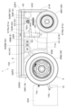
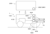
- Figure 57 shows the running body 100 of a work vehicle 1 equipped with a third example of a power transmission mechanism 600, and the harvesting device 200 attached to this running body 100.
- the third example of the power transmission mechanism 600 has a gear transmission mechanism 620 that extracts power from the middle of the lateral output shaft 602 and outputs it above the traveling body 100.
- the gear transmission mechanism 620 includes a plurality of gears.
- the gear transmission mechanism 620 includes a first gear 621, a second gear 622, a third gear 623, and a fourth gear 624.
- the first gear 621 and the second gear 622 are bevel gears.
- the first gear 621 is attached to the middle of the horizontal output shaft 602 and rotates around the axis of the horizontal output shaft 602.
- the second gear 622, the third gear 623, and the fourth gear 624 are arranged in a line in the vertical direction.
- the second gear 622 meshes with the first gear 621. By meshing the first gear 621 and the second gear 622, power can be taken from the middle of the horizontal output shaft 602.
- the third gear 623 is a spur gear located above the second gear 622 and meshes with the second gear 622.
- the fourth gear 624 is a spur gear located above the third gear 623 and meshes with the third gear 623.
- the fourth gear 624 is located near the upper end of the vehicle body 2.
- the fourth gear 624 is an output gear 624 that outputs the power extracted from the middle of the lateral output shaft 602 above the traveling body 100.
- the number of gears constituting the gear transmission mechanism 620 can be changed (increased or decreased) as appropriate.
- the number of three gears (first gear 621, third gear 623, fourth gear 624) that are aligned vertically and meshed can be increased or decreased.
- the diameter of the gears is adjusted so that the uppermost gear (output gear) is positioned near the upper end of the vehicle body 2.
- the harvesting device 200 mounted on the running body 100 of the work vehicle 1 equipped with the third example of the power transmission mechanism 600 has a power input unit 280 to which the power output from the power transmission mechanism 600 to the upper part of the running body 100 is input.
- the harvesting device 200 has an input gear 282 as the power input unit 280, which meshes with the output gear 624 (fourth gear 624) of the gear transmission mechanism 620.
- the above-mentioned configuration of the digging device is only one example, and the configuration of the digging device is not limited to the above-mentioned configuration.
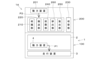
- FIG. 62 is a diagram showing an example (first example) of a power transmission path for the harvester 1A when the harvesting device 200 is a digging device that digs up crops.
- the harvesting device 200 is a digging device that digs up crops.
- power is supplied to the harvesting device (digging device) 200 from the power unit 4 mounted on the traveling body 100.
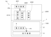
- the power generated by the power unit 4 is also supplied to the traveling device 3 of the traveling body 100 (see arrow P1).
- Figures 64 and 65 show the power transmission path of the harvester 1A when the harvesting device 200 is a pull-out device that pulls out crops.
- the harvesting device 200 is equipped with a pull-out section as the harvesting unit 210 (hereinafter referred to as the "pulling unit 210"), a transport section 220, and a storage section 230.
- the pulling-out unit 210 has a clamping section that clamps the stems and leaves of crops (carrots, radishes, etc.) planted in a field from the left and right.
- the pulling-out unit 210 pulls out the crop by pulling up the stems and leaves clamped by the clamping section along an inclined surface as it moves forward.
- the pulling-out unit 210 is located at the front of the harvesting device 200 (the front of the harvester 1A).
- the pulling-out unit 210 is provided at the front (front wheel side) or rear (rear wheel side) of the lower part of the running body 100.
- the conveying section 220 is equipped with a conveyor that conveys the crops pulled out by the pulling section 210 upward (above the running body 100).
- the front part of the conveying section 220 is connected to the pulling section 210.
- the conveying section 220 extends diagonally upward from the part connected to the pulling section 210 to above the running body 100.
- the conveying section 220 conveys the crops pulled out by the pulling section 210 from the front (or rear) of the lower part of the running body 100 to above the running body 100.
- the rear part of the conveying section 220 is connected to the storage section 230.
- the storage section 230 stores the crops transported by the conveying section 220.
- the storage section 230 is located above the running body 100.
- the above-mentioned configuration of the extraction device is just one example, and the configuration of the extraction device is not limited to the above-mentioned configuration.
- the extraction unit 210 may be configured to pull up the stem and leaf portion clamped by the clamping unit by extending and retracting the rod of the cylinder device.
- Figure 64 is a diagram showing an example (first example) of a power transmission path for the harvester 1A when the harvesting device 200 is a removal device.
- power is supplied to the harvesting device (removal device) 200 from the power unit 4 mounted on the traveling body 100.
- the power generated by the power unit 4 is also supplied to the traveling device 3 of the traveling body 100 (see arrow P1).
- the power supplied from the power unit 4 to the harvesting device (pulling device) 200 is input to the power input section 280 of the harvesting device (pulling device) 200.
- the harvesting device (pulling device) 200 can perform the harvesting work (pulling work) based on the power supplied from the power unit 4 mounted on the traveling body 100.
- FIG. 65 is a diagram showing another example (second example) of the power transmission path of the harvester 1A when the harvesting device 200 is a pull-out device.
- the harvesting device (pulling device) 200 has a separate power unit 201 that generates power for performing the harvesting work (pulling work) in addition to the power unit 4 mounted on the traveling body 100. Therefore, as shown by arrow P3, the drive unit (conveyor unit 220) of the harvesting device (pulling device) 200 is supplied with power from the power unit 201 possessed by the harvesting device (pulling device) 200. This drives the drive unit (conveyor unit 220) of the harvesting device 200, allowing the harvesting work (pulling work) to be performed.
- a preferred embodiment of the present invention provides a method for mounting a work vehicle 1, 1A and a work implement 200 as described below.
- a work vehicle 1 comprising a vehicle body 2, a traveling device 3 that supports the vehicle body 2 so that the vehicle body 2 can travel, and a lifting mechanism 90 that can raise and lower the vehicle body 2, the lifting mechanism 90 raising the vehicle body 2 with the vehicle body 2 positioned below the work device 200, and attaching the work device 200.
- the work vehicle 1 makes it possible to mount the work device 200 above the vehicle body 2. Specifically, the vehicle body 2, which is located below the work device 200, is raised by the lifting mechanism 90, so that the work device 200 can be easily mounted above the vehicle body 2.
- the lifting mechanism 90 detaches the working device 200 from the vehicle body 2 by lowering the working device 200 together with the vehicle body 2 toward the platform 150 from a state in which the working device 200 is mounted on the vehicle body 2 and positioned above the platform 150.
- the work vehicle 1 makes it possible to detach the working device 200 mounted on the vehicle body 2. Specifically, by lowering the working device 200 mounted on the vehicle body 2 together with the vehicle body 2 toward the platform 150, the vehicle body 2 can be lowered leaving the working device 200 on the platform 150, and the working device 200 can be detached from the vehicle body 2.
- the power unit 4 includes a battery 7 and motors 5, 6 driven by power supplied from the battery 7, and the lifting mechanism 90 lifts the vehicle body 2 on which the battery 7 and the motors 5, 6 are mounted to mount the work device 200.
- (Item A5) A work vehicle 1 according to any one of items A1 to A4, in which the vehicle body 2 is provided with an attachment/detachment mechanism 400 that enables the working device 200 to be attached and detached to the vehicle body 2.
- the attachment/detachment mechanism 400 allows the work device 200 to be attached to and detached from the vehicle body 2.
- the work device 200 can be fixed to the vehicle body 2 by the locking mechanism 420 while the work device 200 is placed on the vehicle body 2. This makes it possible to reliably prevent the work device 200 from coming off the vehicle body 2 during work, etc.
- (Item A7) A work vehicle 1 described in items A1 to A6, in which a convex portion 401 that protrudes upward is provided on the upper portion of the vehicle body 2, and a concave portion 501 into which the convex portion 401 fits when the work device 200 is attached to the vehicle body 2 is provided on the lower portion of the work device 200.
- the recess 501 fits into the protrusion 401, so that the work device 200 can be securely attached to the upper part of the vehicle body 2.
- the convex portion 401 has a first tapered surface 402 that is inclined so that the width of the convex portion 401 narrows toward the top, and the concave portion 501 has a second tapered surface 502 that abuts against the first tapered surface 402 when the working device 200 is attached to the vehicle body 2.
- the second tapered surface 502 abuts against the first tapered surface 402, so that the work device 200 can be accurately positioned and attached to the upper part of the vehicle body 2.
- the work vehicle 1 according to item A9 can be used for harvesting work by positioning the harvesting device 200 mounted on the upper part of the vehicle body 2 at a height suitable for cutting, digging, and uprooting crops.
- a work vehicle 1 comprising a traveling body 100, a power unit 4 mounted on the traveling body 100, a mounting section 400 capable of mounting a work device 200 having a power input section 280 to which power is input to the traveling body 100, and allowing at least the power input section 280 to be mounted on the traveling body 100, and a power transmission mechanism 600 that outputs the power generated by the power unit 4 above the traveling body 100 so that it can be transmitted to the work device 200.
- the power generated by the power unit 4 can be output above the traveling body 100 and transmitted to the working device 200. Specifically, the power generated by the power unit 4 can be transmitted to the working device 200 via the power input unit 280 mounted on the traveling body 100 by the mounting unit 400.
- the power transmission mechanism 600 has an upward output shaft 601 that extends upward and outputs the power generated by the power unit 4 above the traveling body 100.
- the power generated by the power unit 4 can be output above the traveling body 100 by the upward output shaft 601. Therefore, the power generated by the power unit 4 can be easily and reliably transmitted to the power input section 280 of the work device 200 mounted on the traveling body 100.
- Item B3 A work vehicle 1 as described in Item B2, which is equipped with a lateral output shaft 602 that outputs the power generated by the power unit 4 forward, backward, or to the side, and the upward output shaft 601 branches off from the middle of the lateral output shaft 602 and extends upward.
- the work vehicle 1 according to item B3 can extract the power generated by the power unit 4 from the middle of the horizontal output shaft 602 and transmit it to the upward output shaft 601 that extends upward.
- (Item B4) A work vehicle 1 described in any of Items B1 to B3, which is equipped with a lateral output shaft 602 that outputs the power generated by the power unit 4 forward, backward, or to the side, and the power transmission mechanism 600 has a change mechanism 610 that can change the lateral output shaft 602 to an upward direction that extends upward.
- Item B6 A work vehicle 1 described in Item B1, which is equipped with a lateral output shaft 602 that outputs the power generated by the power unit 4 forward, backward, or to the side, and the power transmission mechanism 600 has a gear transmission mechanism 620 that extracts power from the middle of the lateral output shaft 602 and outputs it above the traveling body 100.
- the power generated by the power unit 4 can be taken from the middle of the lateral output shaft 602 by the gear transmission mechanism 620 and transmitted to the upper part of the traveling body 100.
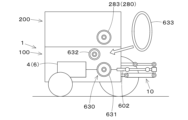
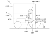
- Item B7 A work vehicle 1 described in Item B1, which is equipped with a lateral output shaft 602 that outputs the power generated by the power unit 4 forward, backward, or to the side, and the power transmission mechanism 600 has a belt transmission mechanism 630 that extracts power from the middle of the lateral output shaft 602 and outputs it above the traveling body 100.
- the power output above the traveling body 100 can be input to the work device 200 attached to the attachment part 400 via the power input part 280.
- the power output by the output pulley 631 to the upper side of the traveling body 100 can be input to the work device 200 attached to the attachment part 400 via the belt 633 and the input pulley 283.
- a work vehicle 1A comprising a traveling body 100, a power unit 4 mounted on the traveling body 100, a work device 200 having a power input section 280 to which power is input, a mounting section 400 that allows the work device 200 to be mounted on the traveling body 100 and at least the power input section 280 to be mounted on the traveling body 100, and a power transmission mechanism 600 that outputs the power generated by the power unit 4 above the traveling body 100 so that it can be transmitted to the work device 200.
Landscapes
- Engineering & Computer Science (AREA)
- Mechanical Engineering (AREA)
- Chemical & Material Sciences (AREA)
- Combustion & Propulsion (AREA)
- Transportation (AREA)
- Life Sciences & Earth Sciences (AREA)
- Soil Sciences (AREA)
- Environmental Sciences (AREA)
- Agricultural Machines (AREA)
Abstract
動力装置から発生する動力を走行機体の上方に出力して作業装置に伝達することができる作業車両を提供する。作業車両(1,1A)は、走行機体(100)と、前記走行機体(100)に搭載された動力装置(4)と、動力が入力される動力入力部(280)を有する作業装置(200)を前記走行機体(100)に装着可能であって、少なくとも前記動力入力部(280)を前記走行機体(100)の上に装着可能とする装着部(400)と、前記動力装置(4)から発生する動力を前記作業装置(200)へ伝達可能に前記走行機体(100)の上方に出力する動力伝達機構(600)と、を備えている。
Description
本発明は、農作業等の作業を行うための作業車両に関する。
従来、下記特許文献1に開示された作業車両が知られている。特許文献1に開示された作業車両(トラクタ)は、走行機体と、走行機体に搭載された動力装置(エンジン)と、動力装置から発生する動力を後方に取り出すための出力軸(PTO軸)と、走行機体の後方に作業装置(耕耘機)を装着するための装着部(3点リンク機構)とを備えている。
上記した作業車両は、動力装置から発生する動力を、出力軸から走行機体の後方に出力して、装着部に装着された作業装置に伝達することができる。しかし、動力装置から発生する動力を走行機体の上方に出力して作業装置に伝達することはできない。
本発明は、上記問題に鑑みてなされたものであって、動力装置から発生する動力を走行機体の上方に出力して作業装置に伝達することができる作業車両を提供することを目的とする。
本発明の一実施形態に係る作業車両は、走行機体と、前記走行機体に搭載された動力装置と、動力が入力される動力入力部を有する作業装置を前記走行機体に装着可能であって、少なくとも前記動力入力部を前記走行機体の上に装着可能とする装着部と、前記動力装置から発生する動力を前記作業装置へ伝達可能に前記走行機体の上方に出力する動力伝達機構と、を備えている。
前記動力伝達機構は、上方に向けて延伸して前記動力装置から発生する動力を前記走行機体の上方に出力する上向き出力軸を有していてもよい。
前記動力装置から発生する動力を前方又は後方又は側方に出力する横向き出力軸を備え、前記上向き出力軸は、前記横向き出力軸の中途部から分岐して上方に向けて延伸していてもよい。
作業車両は、前記動力装置から発生する動力を前方又は後方又は側方に出力する横向き出力軸を備え、前記動力伝達機構は、前記横向き出力軸を上方に向けて延伸する上向きに変更可能とする変更機構を有していてもよい。
前記変更機構は、前記走行機体の前方又は後方に位置する第2作業装置を昇降する昇降装置を含み、前記昇降装置は、前記第2作業装置が装着されない場合に前記横向き出力軸を上向きに変更するようにしてもよい。
作業車両は、前記動力装置から発生する動力を前方又は後方又は側方に出力する横向き出力軸を備え、前記動力伝達機構は、前記横向き出力軸の中途部から動力を取り出して前記走行機体の上方に出力する歯車伝達機構を有していてもよい。
作業車両は、前記動力装置から発生する動力を前方又は後方又は側方に出力する横向き出力軸を備え、前記動力伝達機構は、前記横向き出力軸の中途部から動力を取り出して前記走行機体の上方に出力するベルト伝達機構を有していてもよい。
作業車両は、前記装着部に装着される作業装置を備え、前記作業装置は、前記動力伝達機構から前記走行機体の上方に出力された動力が入力される動力入力部を有していてもよい。
前記作業装置は、前記動力入力部として、前記上向き出力軸と接続される下向き入力軸を有していてもよい。
前記作業装置は、前記動力入力部として、上向きに変更された前記横向き出力軸と接続される下向き入力軸を有していてもよい。
前記歯車伝達機構は、前記横向き出力軸の中途部から取り出した動力を前記走行機体の上方に出力する出力歯車を有し、前記作業装置は、前記動力入力部として、前記出力歯車と噛み合う入力歯車を有していてもよい。
前記ベルト伝達機構は、前記横向き出力軸の中途部から動力を取り出す出力プーリと、前記出力プーリに掛けられて前記出力プーリから動力を伝達するベルトと、を有し、前記作業装置は、前記動力入力部として、前記ベルトが掛けられて前記出力プーリから動力が伝達される入力プーリを有していてもよい。
作業車両は、走行機体と、前記走行機体に搭載された動力装置と、動力が入力される動力入力部を有する作業装置と、前記作業装置を前記走行機体に装着可能であって、少なくとも前記動力入力部を前記走行機体の上に装着可能とする装着部と、前記動力装置から発生する動力を前記作業装置へ伝達可能に前記走行機体の上方に出力する動力伝達機構と、を備えている。
本発明に係る作業車両によれば、動力装置から発生する動力を走行機体の上方に出力して作業装置に伝達することができる。
以下、本発明に係る作業車両1の好適な実施形態について説明する。作業車両1が行う作業としては、例えば、農業に関する作業、工業(土木、建築等)に関する作業、輸送に関する作業等が挙げられるが、これらの作業には限定されない。本発明の好適な実施形態の場合、作業車両1が行う作業は農業に関する作業(農作業)である。以下、作業車両1により行われる作業が農作業である場合を例として説明する。この場合、作業車両1は、農作業車両である。
図1~図7は、作業車両1の一実施形態を示す図である。図1は、作業車両1の斜視図である。図2は、作業車両1の左側面図である。図3は、作業車両1の右側面図である。図4は、作業車両1の正面図である。図5は、作業車両1の背面図である。図6は、作業車両1の平面図である。図7は、作業車両1の全体構成を示すブロック図である。
図1~図6に示すように、作業車両1は、走行機体100と、走行機体100に搭載された動力装置4(図2,図3参照)とを備えている。走行機体100は、車体2と、車体2を走行可能に支持する走行装置3とを備えている。本実施形態の場合、車体2は、内部空間を有する略直方体形状に形成されている。但し、車体2の形状は、略直方体形状には限定されない。車体2の内部空間には、各種の装置や機器が収容されている。
図2,図3に示すように、車体2の内部空間には、走行装置3を駆動させるための動力装置4が搭載(収容)されている。動力装置4は、走行装置3を駆動させる動力を発生し、当該動力が走行装置3に供給される。図7に示すように、動力装置4は、モータ5及びバッテリ7を含む。本実施形態の場合、車体2には、動力装置4として、バッテリ7が搭載(収容)されている。
モータ5は、走行装置3を駆動させる動力を発生する走行系モータである。モータ5は、電力によって駆動する電動モータである。モータ5には、インバータ23が接続されている。インバータ23は、後述する制御装置15からの制御信号に基づいてモータ5の回転を制御する。バッテリ7は、モータ5に供給される電力を蓄電する。但し、動力装置4は、モータ5に代えてエンジンを含むものであってもよい。また、動力装置4は、燃料電池を含むものであってもよい。
図7に示すように、動力装置4は、走行系モータであるモータ5に加えて、作業系モータであるモータ6を備えている。作業系モータは、走行装置3とは異なる装置や機構を駆動させる動力を発生させる。モータ6は、バッテリ7から供給される電力によって駆動する電動モータである。モータ6の回転はインバータ23により制御することができる。以下、モータ5を「走行系モータ5」と表記し、モータ6を「作業系モータ6」と表記する場合がある。
モータ(走行系モータ5、作業系モータ6)は、車体2に搭載することができる。走行系モータ5と作業系モータ6とは、互いに独立して駆動することができる。作業系モータ6は、後述する油圧シリンダを作動させる油圧ポンプを駆動させるためのモータである。また、作業系モータ6は、外部出力軸を駆動させるためのモータでもある。
外部出力軸は、作業系モータ6の動力を車体2の外部に取り出すための出力軸である。つまり、作業車両1は、作業系モータ6の動力を車体2の外部に取り出すための外部出力軸を備えている。外部出力軸は、例えばPTO軸である。作業車両1は、外部出力軸として、後述する上向き出力軸601及び/又は横向き出力軸602を備えている(図50~図61参照)。上向き出力軸601と横向き出力軸602については、後程、詳しく説明する。
作業系モータ6は、油圧モータであってもよい。油圧モータは、油圧ポンプから供給される作動油によって駆動する。この場合、例えば、走行系モータ5により油圧ポンプを駆動し、油圧ポンプから供給される作動油によって油圧モータ(作業系モータ6)を駆動し、当該油圧モータの駆動によって外部出力軸を駆動する。また、作業車両1は、電動モータである作業系モータ6とは別に、油圧モータである作業系モータ6を備えていてもよい。
上述した通り、動力装置4の一部であるバッテリ7は、車体2に収容されている(図2,図3参照)。また、図示していないが、車体2には、さらに動力装置4(モータ5、モータ6、バッテリ7等)を冷却する冷却システム(ラジエータ、ファン、ウォーターポンプ、コンプレッサ等)と、制御装置15からの制御信号に基づいて後述する油圧シリンダ(シリンダ62、昇降シリンダ91)等を作動するための油圧システム(コントロールバルブ等)が収容されている。
車体2は、走行装置3の駆動によって走行可能である。図4,図5等に示すように、走行装置3は、車体2の左方に設けられた左走行装置3Lと、車体2の右方に設けられた右走行装置3Rとを含む。車体2は、左走行装置3Lと右走行装置3Rとの間にある。図2に示すように、左走行装置3Lは、左前輪3LFと左後輪3LBとを含む。図3に示すように、右走行装置3Rは、右前輪3RFと右後輪3RBとを含む。以下、説明の便宜上、左前輪3LF、右前輪3RF、左後輪3LB、右後輪3RBをまとめて「車輪30」と表記する場合がある。
車輪30(左前輪3LF、右前輪3RF、左後輪3LB、右後輪3RB)は、車体2の側方に配置されている。左前輪3LFと左後輪3LBは、車体2の左方に配置されている。右前輪3RFと右後輪3RBは、車体2の右方に配置されている。本実施形態の作業車両1の走行機体100の場合、後輪(左後輪3LB、右後輪3RB)の大きさ(直径及び幅)は、前輪(左前輪3LF、右前輪3RF)の大きさ(直径及び幅)よりも大きい。但し、前輪(左前輪3LF、右前輪3RF)の大きさと後輪(左後輪3LB、右後輪3RB)の大きさは、同じであってもよいし、前輪の大きさが後輪の大きさよりも大きくてもよい。
本実施形態の場合、走行装置3は、前輪(左前輪3LF、右前輪3RF)と後輪(左後輪3LB、右後輪3RB)が全てタイヤで構成された車輪型の走行装置である。但し、走行装置3は、左走行装置3L及び右走行装置3Rがクローラから構成されたクローラ型の走行装置であってもよい、また、走行装置3は、前輪と後輪のいずれか一方が車輪であっていずれか他方がクローラから構成された走行装置であってもよい。
図1~図3に示すように、作業車両1の走行機体100は、左後輪3LBの上方及び前方を覆うフェンダ55Lと、右後輪3RBの上方及び前方を覆うフェンダ55Rと、を備えている。フェンダ55L,55Rは、後述するフレーム構造体18に取り付けられている。図示していないが、走行機体100は、前輪(左前輪3LF、右前輪3RF)を覆うフェンダを備えていてもよい。
図7に示すように、作業車両1は、変速装置9を備えている。変速装置9は、変速によって走行装置3の推進力を切り換え可能である。また、変速装置9は、走行装置3の前進と後進の切り換えが可能である。変速装置9は、4つの車輪(左前輪3LF、右前輪3RF、左後輪3LB、右後輪3RB)の全てが駆動する四輪駆動状態(4WD)と、後輪(左後輪3LB、右後輪3RB)のみ又は前輪(左前輪3LF、右前輪3RF)のみが駆動する二輪駆動状態(2WD)とを切り換え可能な変速クラッチを備えていてもよい。
作業車両1は、後述する作業装置200とは別の作業装置300を装着して昇降可能な昇降装置10を備えている。以下、説明の便宜上、別の作業装置300を「第2作業装置300」という。図2,図3に示すように、昇降装置10には、第2作業装置300を着脱可能に装着することができる。昇降装置10は、車体2の後部に設けられている。図5は、昇降装置10を後方から見た図である。但し、昇降装置10は、車体2の前部又は側部(左部又は右部)に設けてもよい。
昇降装置10に装着される第2作業装置300の種類は特に限定されない。例えば、第2作業装置300として、農業に関する作業(農作業)を行う装置、土木に関する作業を行う装置、建築に関する作業を行う装置、輸送に関する作業等を行う装置が挙げられる。
農作業を行う第2作業装置300としては、例えば、肥料や薬剤等の散布物を散布する散布装置、種を撒く播種装置、土壌を耕耘する耕耘装置、土壌を耕起する耕起装置(プラウ)、除草を行う除草装置、土を寄せる土寄せ装置等が挙げられる。
昇降装置10に装着される第2作業装置300は、作業系モータ6の動力を車体2の外部に取り出すための外部出力軸(後述する上向き出力軸601及び/又は横向き出力軸602)から伝達される動力によって駆動することができる。第2作業装置300が電動式の作業装置である場合、外部出力軸から取り出される動力で駆動する代わりに、バッテリ7から電力線を介して車体2の外部に取り出した電力により駆動してもよい。
昇降装置10は、3点リンク機構から構成されている。具体的には、図5に示すように、昇降装置10は、リフトアーム10a、ロアリンク10b、トップリンク10c、リフトロッド10d、リフトシリンダ10eを有している。リフトアーム10aの前端部は、車体2の後上部に上方又は下方に揺動可能に支持されている。リフトアーム10aは、リフトシリンダ10eの駆動によって揺動(昇降)する。リフトシリンダ10eは、油圧シリンダから構成されている。リフトシリンダ10eは、コントロールバルブ(図示略)を介して油圧ポンプ(図示略)と接続されている。
油圧ポンプは、作業系モータ6によって駆動される。コントロールバルブは、制御装置15によって流路の開閉等が制御される電磁弁等である。油圧ポンプから吐出される作動油の流れをコントロールバルブで制御することによって、リフトシリンダ10eを伸縮させることができる。
ロアリンク10bの前端部は、車体2の後下部に上方又は下方に揺動可能に支持されている。トップリンク10cの前端部は、ロアリンク10bよりも上方において、車体2の後部に上方又は下方に揺動可能に支持されている。リフトロッド10dは、リフトアーム10aとロアリンク10bとを連結している。ロアリンク10bの後部及びトップリンク10cの後部には、第2作業装置300が連結される。リフトシリンダ10eが駆動(伸縮)すると、リフトアーム10aが昇降するとともに、リフトロッド10dを介してリフトアーム10aと連結されたロアリンク10bが昇降する。これにより、第2作業装置300がロアリンク10bの前部を支点として、上方又は下方に揺動(昇降)する。
昇降装置10に装着された第2作業装置300は、作業車両1の走行に伴って、作業車両1に牽引されて移動する。尚、昇降装置10には、第2作業装置300に代えて農作物等を運搬する台車等を装着してもよい。
図7に示すように、作業車両1は、測位装置11を備えている。測位装置11は、D-GPS、GPS、GLONASS、北斗、ガリレオ、みちびき等の衛星測位システム(測位衛星)により、車体2の位置(緯度、経度を含む測位情報)を検出可能である。即ち、測位装置11は、測位衛星から送信された衛星信号(測位衛星の位置、送信時刻、補正情報等)を受信し、衛星信号に基づいて、車体2の位置(例えば、緯度、経度)を検出する。
測位装置11は、受信装置12と、慣性計測装置(IMU:Inertial Measurement Unit)13とを有している。受信装置12は、アンテナ等を有していて測位衛星から送信された衛星信号を受信する装置であり、車体2に取り付けられている。慣性計測装置13は、加速度を検出する加速度センサ、角速度を検出するジャイロセンサ等を有している。慣性計測装置13は、車体2に取り付けられている。慣性計測装置13によって、車体2のロール角、ピッチ角、ヨー角等を検出することができる。尚、ヨー角については、測位装置11を複数設置することによって検出してもよい。
図7に示すように、作業車両1は、通信装置14を備えている。通信装置14には、車載ネットワークを介した通信を行うための通信回路と、無線通信を行うための無線通信回路とが含まれている。当該無線通信回路は、通信規格であるIEEE802.11シリーズのWi-Fi(Wireless Fidelity、登録商標)、BLE(Bluetooth(登録商標) Low Energy)、LPWA(Low Power, Wide Area)、LPWAN(Low-Power Wide-Area Network)等により、外部機器と直接又は間接的に無線で通信を行うことができる。他の例として、例えば携帯電話通信網又はデータ通信網等により、外部機器と無線で通信可能な通信回路を通信装置14に設けてもよい。外部機器は、例えばパーソナルコンピュータ、スマートフォン、タブレットコンピュータ、PDA、又はサーバ等である。外部機器は、例えば、後述する操作装置80を含むことができる。
図7に示すように、作業車両1は、制御装置15を備えている。制御装置15は、走行機体100に搭載されている。制御装置15は、作業車両1の様々な制御を行う装置である。制御装置15は、演算部(CPU等)及び記憶部(RAM,ROM等)を備えている。記憶部は、制御装置15の外部に設けられた外部メモリを含んでいてもよい。制御装置15は、CAN(Controller Area Network)等の車内LAN(車載ネットワーク)又は通信線を介して、図7に示された各種の装置や機構と接続されている。
制御装置15は、記憶部に記憶された各種の制御プログラムを演算部が実行することによって、制御装置15と通信可能に接続された各種の装置や機構の動作を制御する。後述する制御装置15の各制御部(自動運転制御部15A、高さ変更制御部15B)の機能は、記憶部に記憶された所定の制御プログラムを演算部が実行することによって実現される。
図7に示すように、制御装置15は、自動運転制御部15Aを含む。自動運転制御部15Aは、走行機体100の自動運転の制御を行う。つまり、走行機体100は、自動運転を行う制御装置15を備えている。自動運転制御部15Aは、ライン型自動運転制御と自律型自動運転制御とを実行可能である。ライン型自動運転制御では、自動運転制御部15Aは、予め設定された走行予定ラインに沿って走行機体100(車体2)が移動するように、後述する操舵機構60、変速装置9、モータ5等の動作を制御する。
自律型自動運転制御では、自動運転制御部15Aは、測位装置11等によって走行機体100(車体2)の周囲をセンシング(対象物を検出)した結果に基づいて、車体2の進行方向(操舵方向)及び車速(速度)等の設定を行い、設定された操舵及び車速になるように、操舵機構60、変速装置9、及びモータ5等の動作を制御する。
なお、ライン型自動運転制御と自律型自動運転制御とを、スイッチ等で切り換えることができるようにしてもよい。また、ライン型自動運転制御と自律型自動運転制御のうちのいずれか一方を実行可能に、自動運転制御部15Aを構成してもよい。但し、自動運転制御部15Aの構成は、上記した構成には限定されない。
作業車両1は、走行機体100の制御装置15が自動運転制御部15Aを含むことによって、オペレータが乗車せずに自動走行(無人走行)を行うことができる。そのため、図示の実施形態の走行機体100は、オペレータが着座する運転席を有していない。但し、作業車両1は、オペレータが乗車して自動走行を行う車両であってもよい。或いは、作業車両1は、オペレータが乗車して運転して走行を行う車両であってもよい。作業車両1が、オペレータが乗車する車両である場合、車体2に運転席が備えられる。
図7に示すように、作業車両1は、照明装置16を備えている。照明装置16は、車体2に設けられている。照明装置16は、少なくとも車体2の前方を照らす前照灯を含む。照明装置16は、前照灯に加えて、車体2の周囲を照らす複数の作業灯を含んでいてもよい。作業灯は、例えば、車体2の側方(左方、右方)や車体2の後方を照らすことができる。また、照明装置16は、状態表示灯、左右灯、ブレーキランプ等を含んでいてもよい。
図7に示すように、作業車両1は、報知装置17を備えている。報知装置17は、音や光等によって車体2の周囲にいる人に危険(車体2の接近等)を報知する。報知装置17は、スピーカや警告灯等から構成される。
図1~図6等に示すように、走行機体100は、車体2の周囲に配置され且つ車体2に取り付けられたフレーム構造体18を備えている。フレーム構造体18は、左フレーム18Lと右フレーム18Rとを含む。左フレーム18Lと右フレーム18Rは、車体2の側方に配置されたフレームである。
左フレーム18Lは、車体2の左方に設けられている。左フレーム18Lは、車体2に沿って上下方向に延びている。左フレーム18Lは、車体2に沿って前後方向にも延びている。左フレーム18Lは、左前輪3LFと左後輪3LBとを接続している。
右フレーム18Rは、車体2の右方に設けられている。右フレーム18Rは、車体2に沿って上下方向に延びている。右フレーム18Rは、車体2に沿って前後方向にも延びている。右フレーム18Rは、右前輪3RFと右後輪3RBとを接続している。
図4に示すように、車体2は、正面視において、左フレーム18Lと右フレーム18Rとの間に配置されている。言い換えれば、車体2は、左フレーム18Lと右フレーム18Rとの間に挟まれる位置に配置されている。
図8に示すように、左フレーム18Lは、第1左フレーム19Lと第2左フレーム20Lとから構成されている。第1左フレーム19Lは、第1前支柱19L1、第1後支柱19L2、第1接続体19L3から構成されている。第1前支柱19L1と第1後支柱19L2とは、前後方向に間隔を空けて配置され、互いに平行に上下方向に延びている。図1,図4に示すように、第1前支柱19L1は、車体2の前部の左方に配置されている。図5に示すように、第1後支柱19L2は、車体2の後部の左方に配置されている。第1前支柱19L1及び第1後支柱19L2は、筒状(四角筒状)に形成されている。
図9に示すように、第1接続体19L3は、第1前支柱19L1と第1後支柱19L2とを接続している。第1接続体19L3は、フレーム材19AL、フレーム材19BL、フレーム材19CL、フレーム材19DL、フレーム材19ELから構成されている。フレーム材19ALは、前後方向に延びており、第1前支柱19L1の上部と第1後支柱19L2の上部とを接続している。フレーム材19BLは、フレーム材19ALの左方にて前後方向に延びている。フレーム材19CLは、フレーム材19ALの前部とフレーム材19BLの前部とを接続している。フレーム材19DLは、フレーム材19ALの後部とフレーム材19BLの後部とを接続している。フレーム材19ELは、フレーム材19ALの前後方向の中途部とフレーム材19BLの前後方向の中途部とを接続している。
図9に示すように、第2左フレーム20Lは、第2前支柱20L1、第2後支柱20L2、第2接続体20L3から構成されている。第2前支柱20L1と第2後支柱20L2とは、前後方向に間隔を空けて配置され、互いに平行に上下方向に延びている。第2接続体20L3は、第2前支柱20L1と第2後支柱20L2とを接続している。第2接続体20L3は、前後方向に延びており、第2前支柱20L1の上部と第2後支柱20L2の上部とを接続している。
図9の下向き矢印に示すように、第2前支柱20L1は、筒状の第1前支柱19L1の内部に上方から挿入される。第2後支柱20L2は、筒状の第1後支柱19L2の内部に上方から挿入される。これにより、第1左フレーム19Lと第2左フレーム20Lとが合体される(図8参照)。第2前支柱20L1は、第1前支柱19L1に沿って上下方向に移動することができる。第2後支柱20L2は、第1後支柱19L2に沿って上下方向に移動することができる。これにより、第2左フレーム20Lは、第1左フレーム19Lに対して上下方向に移動することができる。
図9に示すように、右フレーム18Rは、第1右フレーム21Rと第2右フレーム22Rとから構成されている。第1右フレーム21Rは、第1前支柱21R1、第1後支柱21R2、第1接続体21R3から構成されている。第1前支柱21R1と第1後支柱21R2とは、前後方向に間隔を空けて配置され、互いに平行に上下方向に延びている。図1,図4に示すように、第1前支柱21R1は、車体2の前部の右方に配置されている。図5に示すように、第1後支柱21R2は、車体2の後部の右方に配置されている。第1前支柱21R1及び第1後支柱21R2は、筒状(四角筒状)に形成されている。
第1接続体21R3は、第1前支柱21R1と第1後支柱21R2とを接続している。第1接続体21R3は、フレーム材21AR、フレーム材21BR、フレーム材21CR、フレーム材21DR、フレーム材21ERから構成されている。フレーム材21ARは、前後方向に延びており、第1前支柱21R1の上部と第1後支柱21R2の上部とを接続している。フレーム材21BRは、フレーム材21ARの右方にて前後方向に延びている。フレーム材21CRは、フレーム材21ARの前部とフレーム材21BRの前部とを接続している。フレーム材21DRは、フレーム材21ARの後部とフレーム材21BRの後部とを接続している。フレーム材21ERは、フレーム材21ARの前後方向の中途部とフレーム材21BRの前後方向の中途部とを接続している。
第2右フレーム22Rは、第2前支柱22R1、第2後支柱22R2、第2接続体22R3から構成されている。第2前支柱22R1と第2後支柱22R2とは、前後方向に間隔を空けて配置され、互いに平行に上下方向に延びている。第2接続体22R3は、第2前支柱22R1と第2後支柱22R2とを接続している。第2接続体22R3は、前後方向に延びており、第2前支柱22R1の上部と第2後支柱22R2の上部とを接続している。
図9の下向き矢印に示すように、第2前支柱22R1は、筒状の第1前支柱21R1の内部に上方から挿入される。第2後支柱22R2は、筒状の第1後支柱21R2の内部に上方から挿入される。これにより、第1右フレーム21Rと第2右フレーム22Rとが合体される(図8参照)。第2前支柱22R1は、第1前支柱21R1に沿って上下方向に移動することができる。第2後支柱22R2は、第1後支柱21R2に沿って上下方向に移動することができる。これにより、第2右フレーム22Rは、第1右フレーム21Rに対して上下方向に移動することができる。
車体2は、第2左フレーム20L及び第2右フレーム22Rに取り付けられている。車体2の左部(左側面)は、第2左フレーム20Lに取り付けられている。車体2の右部(右側面)は、第2右フレーム22Rに取り付けられている。具体的には、車体2の左部(左側面)は、第2左フレーム20Lの第2接続体20L3に取り付けられている。車体2の右部(右側面)は、第2右フレーム22Rの第2接続体22R3に取り付けられている。
車体2の第2左フレーム20L(第2接続体20L3)及び第2右フレーム22R(第2接続体22R3)への取り付け方法は、特に限定されず、例えば、ボルト等の締結具により着脱可能に取り付けてもよいし、溶接や接着等により取り付けてもよい。
上述した通り、車体2は、第2左フレーム20L及び第2右フレーム22Rに取り付けられているため、左フレーム18L及び右フレーム18Rと一体に移動することができる。そのため、左フレーム18L及び右フレーム18Rが第1左フレーム19L及び第1右フレーム21Rに対して上下方向に移動したとき、車体2は第2左フレーム20L及び第2右フレーム22Rと共に上下方向に移動する。
フレーム構造体18は、走行装置3が取り付けられた固定フレーム31と、車体2に取り付けられた可動フレーム32とを有している。固定フレーム31は、上下方向に移動しないフレームである。可動フレーム32は、上下方向に移動可能なフレームである。フレーム構造体18のうち、第2左フレーム20Lと第2右フレーム22Rは、可動フレーム32である。第1左フレーム19Lと第1右フレーム21Rは、固定フレーム31である。車体2は、可動フレーム32と共に固定フレーム31に対して上下方向に移動、即ち昇降する。
後述する高さ変更機構90は、固定フレーム31に対して可動フレーム32を昇降することによって、車体2の地面からの高さを変更する。固定フレーム31には、走行装置3が取り付けられている。詳しくは、第1左フレーム19Lには、左走行装置3Lが取り付けられている。第1右フレーム21Rには、右走行装置3Rが取り付けられている。固定フレーム31に対して可動フレーム32が昇降したとき、走行装置3に対して車体2が昇降する。これにより、車体2の地面からの高さが変更される。
尚、フレーム構造体18の構成は、図示した構成には限定されない。例えば、フレーム構造体18は、第2左フレーム20Lと第2右フレーム22Rとを接続する接続フレームを備えていてもよい。この場合、接続フレームは、例えば、第2左フレーム20Lの上部と第2右フレーム22Rの上部とを接続することができる。この場合、接続フレームも可動フレーム32となる。
図7に示すように、作業車両1は、車輪(左前輪3LF、右前輪3RF、左後輪3LB、右後輪3RB)を駆動するための駆動ユニット40を備えている。駆動ユニット40は、動力を発生する駆動装置45と、駆動装置45から発生した動力を車輪30に伝達する伝達機構50と、車輪(左前輪3LF、右前輪3RF)の向きを変化させる操舵機構60とを有している。本実施形態の場合、操舵機構60は、前輪(左前輪3LF、右前輪3RF)の向きを変化させる機構であるが、後輪(左後輪3LB、右後輪3RB)の向きを変化させる機構としてもよい。また、操舵機構60は、前輪の向きと後輪の向きの両方を変化させる機構としてもよい。
図2,図3に示すように、駆動ユニット40は、左前輪3LFを駆動するための第1駆動ユニット41と、右前輪3RFを駆動するための第2駆動ユニット42と、左後輪3LBを駆動するための第3駆動ユニット43と、右後輪3RBを駆動するための第4駆動ユニット44と、を含む。第1駆動ユニット41、第2駆動ユニット42、第3駆動ユニット43及び第4駆動ユニット44は、それぞれ後述する駆動装置45及び伝達機構50を有している。第1駆動ユニット41と第2駆動ユニット42は、それぞれ後述する操舵機構60を有している。各駆動ユニットは、フレーム構造体18に取り付けられている。
本実施形態の場合、駆動装置45はモータである。詳しくは、駆動装置45は、上述した走行系モータ5である。つまり、駆動装置45を構成するモータは、上述した動力装置4に含まれるモータと同じである。以下に説明する通り、駆動ユニット40の駆動装置45を構成するモータ5は、モータ5LFとモータ5RFとモータ5LBとモータ5RBを含む。
図2に示すように、第1駆動ユニット41は、モータ5LFと、モータ5LFの動力を左前輪3LFに伝達する伝達機構50LFと、を有している。伝達機構50LFは、複数の歯車を含む歯車機構等から構成されている。第1駆動ユニット41は、モータ5LFを駆動させると、モータ5LFの動力が伝達機構50LFを介して左前輪3LFに伝達される。
図3に示すように、第2駆動ユニット42は、モータ5RFと、モータ5RFの動力を右前輪3RFに伝達する伝達機構50RFと、を有している。伝達機構50RFは、複数の歯車を含む歯車機構等から構成されている。第2駆動ユニット42は、モータ5RFを駆動させると、モータ5RFの動力が伝達機構50RFを介して右前輪3RFに伝達される。
図2に示すように、第3駆動ユニット43は、モータ5LBと、モータ5LBの動力を左後輪3LBに伝達する伝達機構50LBと、を有している。伝達機構50LBは、複数の歯車を含む歯車機構等から構成されている。第3駆動ユニット43は、モータ5LBを駆動させると、モータ5LBの動力が伝達機構50LBを介して左後輪3LBに伝達される。
図3に示すように、第4駆動ユニット44は、モータ5RBと、モータ5RBの動力を右後輪3RBに伝達する伝達機構50RBと、を有している。伝達機構50RBは、複数の歯車を含む歯車機構等から構成されている。第4駆動ユニット44は、モータ5RBを駆動させると、モータ5RBの動力が伝達機構50RBを介して右後輪3RBに伝達される。
図7に示すように、駆動ユニット40は、車輪30の向きを変化させる操舵機構60を有している。本実施形態の場合、操舵機構60は、車輪30のうち、前輪(左前輪3LFと右前輪3RF)の向きを変化させる機構である。図2,図3に示すように、操舵機構60は、左前輪3LFの向きを変化させる左操舵機構60Lと、右前輪3RFの向きを変化させる右操舵機構60Rと、を含む。
図2に示すように、第1駆動ユニット41は、左操舵機構60Lを備えている。図3に示すように、第2駆動ユニット42は、右操舵機構60Rを備えている。左操舵機構60Lは、シリンダ62を駆動してロッド62aを伸縮することによって、左前輪3LFを軸心AX1回りに回転させることができる。同様に、右操舵機構60Rは、シリンダ62を駆動してロッド62aを伸縮することによって、右前輪3RFを軸心AX2回りに回転させることができる。このように、操舵機構60を駆動して、左前輪3LFと右前輪3RFの向きを変更することによって、走行機体100の進行方向を変更することができる。
尚、駆動装置45の異なる実施形態として、駆動装置45のモータをホイルインモータとしてもよい。この場合、左前輪3LF、右前輪3RF、左後輪3LB、右後輪3RBの全てをホイルインモータにより駆動してもよいし、一部(例えば、左前輪3LFと右前輪3RF、又は左後輪3LBと右後輪3RB)をホイルインモータにより駆動してもよい。
図7に示すように、作業車両1は、第1検出装置70を備えている。第1検出装置70は、車体2の周囲の状況を検出する。第1検出装置70により検出される車体2の周囲の状況は、例えば、車体2の走行を阻害する障害物等である。
図7に示すように、第1検出装置70は、カメラ(撮像装置)71、センサ72、算出部73を有している。本実施形態の場合、第1検出装置70は、カメラ71とセンサ72の両方を備えているが、いずれか一方のみを備えるものであってもよい。
カメラ71は、CCD(Charge Coupled Devices)イメージセンサを搭載したCCDカメラや、CMOS(Complementary Metal Oxide Semiconductor)イメージセンサを搭載したCMOSカメラ等から構成される。カメラ71は、車体2に搭載されて車体2の周囲を撮像する。カメラ71は、車体2の前方、後方、左方、右方のうち、少なくとも車体2の進行方向を含む一方向以上を撮像することができればよい。好ましくは、カメラ71は、車体2の前方、後方、側方(左方、右方)を撮像するように配置される。カメラ71は、車体2の前方、後方、側方(左方、右方)以外の方向(例えば、右前方、左前方、前下方、後下方等)を撮像できるように配置してもよい。
カメラ71は、車体2の周囲を撮像して、画像信号を生成する。算出部73は、生成された画像信号を処置する信号処理回路を含むコンピュータ等からなる。信号処理回路は、カメラ71から出力された画像信号に基づいて、対象物の状態(対象物の有無、対象物の位置、対象物の種類、対象物の大きさ等)を検出する。対象物には、前述した障害物等が含まれる。
センサ72は、光学式のセンサであって、例えば、ライダー(LiDAR: Light Detection And Ranging)から構成される。ライダー(レーザセンサ)は、レーザダイオード等の光源から1秒間に何百万回ものパルス状の測定光(レーザ光)を照射し、当該測定光を回転ミラーで反射することにより水平方向又は鉛直方向に走査して、所定の検出範囲(センシング範囲)に投光する。そして、ライダーは、測定光の対象物による反射光を、受光素子で受光する。算出部73の信号処理回路は、ライダーの受光素子から出力された受光信号に基づいて、対象物の状態(対象物の有無、対象物の位置、対象物の種類、対象物の大きさ等)を検出する。対象物には、前述した障害物等が含まれる。また、信号処理回路は、ライダーにより測定光を照射してから、反射光を受光するまでの時間に基づいて、対象物までの距離を検出する(TOF(Time of Flight)法)。尚、ライダーによる距離の検出方法は、TOF法以外の方法であってもよい。
センサ72は、音波式のセンサであってもよい。センサ72は、光学式のセンサと音波式のセンサの両方を有していることが好ましいが、いずれか一方を有するものであってもよい。音波式のセンサは、例えば、ソナー等の空中超音波センサから構成される。空中超音波センサは、送波器により測定波(超音波)を所定の検出範囲に発信し、当該測定波が対象物で反射した反射波を受波器で受信する。信号処理回路は、当該受波器から出力された信号に基づいて、対象物の状態(対象物の有無、対象物の位置、対象物の種類、対象物の大きさ等)を検出する。対象物には、前述した障害物等が含まれる。また、信号処理回路は、空中超音波センサにより測定波を発信してから、反射波を受波するまでの時間に基づいて、対象物までの距離を検出する(TOF(Time of Flight)法)。尚、音波式のセンサによる距離の検出方法は、TOF法以外の方法であってもよい。
上述したセンサ72は、車体2に搭載されて車体2の周囲の対象物を検出する。センサ72は、車体2の前方、後方、左方、右方のうち、少なくとも車体2の進行方向を含む一方向以上の対象物を検出することができればよい。好ましくは、センサ72は、車体2の前方、後方、側方(左方、右方)の対象物を検出するように配置される。センサ72は、車体2の前方、後方、側方(左方、右方)以外の方向(例えば、右前方、左前方、前下方、後下方等)の対象物を検出できるように配置してもよい。
図7に示すように、作業車両1の走行機体100は、高さ変更機構90を備えている。高さ変更機構90は、車体2の地面からの高さを変更する。高さ変更機構90は、バッテリ7が収容された車体2を昇降する。高さ変更機構90は、車体2の幅方向(左右方向)における左走行装置3Lと右走行装置3Rとの間の位置にて車体2を昇降する。高さ変更機構90は、車体2に取り付けられたフレーム構造体18を昇降することにより、車体2の地面からの高さを変更する。
図1~図3等に示すように、高さ変更機構90は、昇降シリンダ91を有している。昇降シリンダ91は、フレーム構造体18の可動フレーム32(第2左フレーム20L、第2右フレーム22R)を昇降する。可動フレーム32が昇降することによって車体2が昇降する。そのため、昇降シリンダ91の駆動によって、車体2を昇降させることができる。このように、高さ変更機構90は、車体2を昇降可能な機構である。以下、高さ変更機構90を「昇降機構90」という場合がある。
昇降シリンダ91は、油圧シリンダから構成されている。昇降シリンダ91は、上下方向に伸縮するロッド91aと、ロッド91aを駆動するための作動油が供給されるシリンダチューブ91bとを有している(図1~図3参照)。ロッド91aの先端には、フレーム構造体18が接続されている。昇降シリンダ91は、左昇降シリンダ91Lと右昇降シリンダ91Rとを含む。左昇降シリンダ91Lは、車体2の左方に配置されている。右昇降シリンダ91Rは、車体2の右方に配置されている。
図1,図2に示すように、左昇降シリンダ91Lのロッド91Laは、フレーム構造体18の第2左フレーム20Lに接続されている。詳しくは、左昇降シリンダ91Lのロッド91Laは、第2左フレーム20Lに固定された左板99Lに接続されている。これにより、左昇降シリンダ91Lは、ロッド91Laの伸縮によって左フレーム18Lの可動フレームである第2左フレーム20Lを昇降することができる。
図1,図3に示すように、右昇降シリンダ91Rのロッド91Raは、フレーム構造体18の第2右フレーム22Rに接続されている。詳しくは、右昇降シリンダ91Rのロッド91Raは、第2右フレーム22Rに固定された右板99Rに接続されている。これにより、右昇降シリンダ91Rは、ロッド91Raの伸縮によって右フレーム18Rの可動フレームである第2右フレーム22Rを昇降することができる。
左昇降シリンダ91Lのシリンダチューブ91Lbは、第1左フレーム19Lに固定されたブラケット(図示略)に取り付けられている。右昇降シリンダ91Rのシリンダチューブ91Rbは、第1右フレーム21Rに固定されたブラケット(図示略)に取り付けられている。
左昇降シリンダ91Lのロッド91Laが伸縮すると、第2左フレーム20Lが昇降する。右昇降シリンダ91Rのロッド91Raが伸縮すると、第2右フレーム22Rが昇降する。これにより、昇降シリンダ91(左昇降シリンダ91L、右昇降シリンダ91R)のロッド91aの伸縮に伴ってフレーム構造体18(可動フレーム32)を昇降することができる。フレーム構造体18(可動フレーム32)には車体2が取り付けられているため、昇降シリンダ91のロッド91aの伸縮に伴って車体2を昇降することができる。車体2を昇降することによって、車体2の地面からの高さを変更することができる。
図10は、昇降シリンダ91のロッド91aを伸長して車体2を上昇させた状態を示している。車体2の上昇に伴って、車体2に設けられた昇降装置10も上昇する。そのため、車体2を上昇させることによって、昇降装置10に装着した第2作業装置300を上昇させることができる。また、車体2を上昇させることによって、車体2の上部に装着した収穫装置等の作業装置200(後述する)を上昇させることもできる。
高さ変更機構(昇降機構)90の動作は、制御装置15によって制御される。図7に示すように、制御装置15は、高さ変更制御部15Bを含む。高さ変更制御部15Bは、制御装置15の演算部が記憶部に記憶されたプログラムを実行することにより、高さ変更機構90に対して制御信号を送信する。高さ変更機構90は、高さ変更制御部15Bから送信される制御信号に基づいて駆動する。つまり、高さ変更機構90は、制御装置15による制御に基づいて駆動することによって、車体2の高さを変更する。
高さ変更機構90は、車体2の高さを、予め設定された高さ範囲内において任意の高さに変更可能である。詳しくは、高さ変更機構90は、車体2の高さを、第1高さ(図1参照)と、第1高さよりも高い第2高さ(図10参照)との間で任意に変更可能である。つまり、予め設定された高さ範囲は、第1高さと第2高さとの間の範囲である。本実施形態の場合、昇降シリンダ91のロッドを最も短くしたときの車体2の高さは第1高さとなり、昇降シリンダ91のロッドを最も長くしたときの車体2の高さは第2高さとなる。
第1高さは、高さ変更機構90によって変更可能な車体2の高さの下限の高さ(下限高さ)である。第2高さは、高さ変更機構90によって変更可能な車体2の高さの上限の高さ(上限高さ)である。高さ変更機構90は、車体2の高さを、下限高さである第1高さと、上限高さである第2高さと、上限高さと下限高さとの間の任意の高さ(中間高さ)に変更可能である。
高さ変更機構90は、例えば、操作装置80(図7参照)による高さの指定に対応して車体2の高さを変更することができる。操作装置80は、車体2の高さを指定する操作を行うことができる装置である。操作装置80は、作業車両1の外部にある装置(外部機器)であって、制御装置15と無線又は有線によって通信可能に構成されている。操作装置80は、例えば、リモコン装置、タブレット、スマートフォン、PDA等の携帯型の機器である。
操作装置80は、指定したい車体2の高さを入力する入力部を備えている。入力部は、例えば、押しボタン、回転ダイヤル、タッチパネル等である。オペレータが指定したい高さを操作装置80の入力部から入力すると、入力された指定高さが制御装置15に送信される。制御装置15は、車体2の高さが指定された高さとなるように制御信号を送信して高さ変更機構90の昇降シリンダ91を駆動する。これにより、車体2の高さが、操作装置80により指定された高さに変更される。
上述した通り、車体2は左走行装置3Lと右走行装置3Rとの間に配置されている。高さ変更機構90は、車体2を左走行装置3Lと右走行装置3Rとの間にて昇降させて車体2の高さを変更する。つまり、車体2は、左走行装置3Lと右走行装置3Rとの間に形成された空間を通って上下方向に移動する。
作業車両1は、後述する動力入力部280、装着部400及び動力伝達機構600を備えている。ここでは、動力入力部280、装着部400及び動力伝達機構600の概要のみを記載し、詳細については後述する。作業車両1は、動力が入力される動力入力部280を有する作業装置200を走行機体100に装着可能とする装着部400を備えている。装着部400は、少なくとも作業装置200の動力入力部280を走行機体100上に装着可能とする。また、作業車両1は、動力装置4から発生する動力を作業装置200へ伝達可能に走行機体100の上方に出力する動力伝達機構600を備えている。
装着部400に装着可能な作業装置200は、上述した昇降装置10に装着される第2作業装置300とは別の作業装置である。作業装置200の種類は特に限定されないが、農作業を行う装置が好適に使用される。農作業を行う作業装置200としては、例えば、収穫作業を行う収穫装置が挙げられる。
以下、作業装置200が収穫作業を行う収穫装置であるとして説明し、作業装置200の一例である収穫装置を「収穫装置200」と表記する。但し、作業装置は収穫装置には限定されない。そのため、以下の説明について、収穫装置に特有の構成の説明を除き、収穫装置を作業装置と読み替えることができる。
図11~図14は、収穫装置200が走行機体100に装着された状態の作業車両1を示している。以下、収穫装置200が走行機体100に装着された状態の作業車両を、装着されていない状態の作業車両1と区別するために、「収穫機1A」又は「作業車両1A」という。
図11~図14は、収穫機(作業車両)1Aの一実施形態を示している。図11は、収穫機1Aの前方斜視図である。図12は、収穫機1Aの左側面図である。図13は、収穫機1Aの右側面図である。図14は、収穫機1Aの後方斜視図である。図11~図14に示すように、収穫機1Aは、走行機体100と収穫装置200とを備えている。尚、図11~図14では、収穫装置200の構成を簡略化して示している。
本明細書においては、収穫機1Aが収穫作業時に進行する方向(図11の矢印F方向)を収穫機1Aの前方と定義し、前方と反対側(図11の矢印B方向)を収穫機1Aの後方と定義する。従って、収穫機1Aの前部は収穫装置200の前部(後述する収穫部210等)を含み、収穫機1Aの後部は収穫装置200の後部(後述する放出部250等)を含む。
また、図11の矢印Lで示す方向を収穫機1Aの左方、矢印Rで示す方向を収穫機1Aの右方と定義する。従って、収穫機1Aの左部は収穫装置200の左部(後述する脱穀部240)を含み、収穫機1Aの右部は収穫装置200の右部(後述する収容部230)を含む。
図11~図14に示す実施形態の収穫機1Aは、走行機体100の後部(後輪側)に収穫装置200の前部が載置され、走行機体100の前部(前輪側)に収穫装置200の後部が載置された構成となっている。そのため、図11~図14に示す実施形態の収穫機1Aにおいては、収穫機1A及び収穫装置200の前後と走行機体100の前後とが反対となり、収穫機1A及び収穫装置200の左右と走行機体100の左右とが反対となっている。これにより、収穫機1Aの前部に走行機体100の後輪が位置し、収穫機1Aの後部に走行機体100の前輪が位置している。また、収穫機1Aの左部に走行機体100の右輪が位置し、収穫機1Aの右部に走行機体100の左輪が位置している。
一方、別の実施形態(図15,図31,図39,図43,図47等)では、収穫機1A及び収穫装置200の前後と走行機体100の前後とが一致し、収穫機1A及び収穫装置200の左右と走行機体100の左右とが一致している。そのため、収穫機1Aの前部に走行機体100の前輪が位置し、収穫機1Aの後部に走行機体100の後輪が位置している。また、収穫機1Aの左部に走行機体100の左輪が位置し、収穫機1Aの右部に走行機体100の右輪が位置している。
収穫装置200は、走行機体100の走行に伴って、作物の刈り取り、掘り取り、抜き取りの少なくともいずれか1つの収穫作業を行う装置である。収穫装置200によって刈り取られる作物としては、例えば、稲、麦、大豆、とうもろこし等が挙げられるが、これらに限定はされない。収穫装置200によって掘り取られる作物としては、例えば、じゃがいも、さつまいも、葱、玉葱等が挙げられるが、これらに限定はされない。収穫装置200によって抜き取られる作物としては、例えば、大根、ごぼう、人参等が挙げられるが、これらに限定はされない。
収穫装置200は、収穫部210と搬送部220と収容部230とを備えている。また、収穫装置200は、脱穀部240と放出部250と排出部260を備えている。収穫部210は、作物の刈り取り、掘り取り、抜き取りの少なくともいずれか1つの収穫作業を行う。収穫装置200は、車体2が下降した状態(車体2が第1高さにある状態)で収穫作業を行う。図11~図14は、車体2が下降した状態を示している。
図11~図14に示す実施形態の収穫機1Aが備える収穫装置200は、走行機体100の走行に伴って作物の刈り取りを行う刈り取り装置である。そのため、収穫部210は、作物(稲等)の刈り取りを行う。
収穫部210は、収穫装置200の前部(収穫機1Aの前部)に位置している。収穫部210は、走行機体100の下部の前方又は後方に設けられる。図11~図14に示す実施形態の場合、収穫部210は、走行機体100の後方(後輪側)に設けられているが、収穫部210は走行機体100の前方(前輪側)に設けてもよい(図15参照)。つまり、収穫機1Aは、走行機体100に対する収穫装置200の装着の向き(前後方向の向き)は、図11~図14に示したものと反対向きとしてもよい(図15,図31,図39,図43,図47等参照)。このように、収穫機1Aは、走行機体100に対する収穫装置200の装着の向き(前後方向の向き)は特に限定されず、例えば収穫装置200の種類や収穫作業の内容等によって変更することができる。
収穫部210は、分草具211、掻き込みリール212、切断装置(図示略)等を備えている。分草具211は、走行機体100の走行に伴って作物を左右に分ける機能を有する。掻き込みリール212は、分草具211によって分けられた作物を後方に向けて掻き込む。切断装置は、掻き込みリール212により掻き込まれた作物の株元を切断する。
搬送部220は、収穫部210で収穫された作物を走行機体100の上に搬送する。詳しくは、搬送部220は、収穫部210で収穫された作物を、走行機体100の下部の前方(又は後方)から走行機体100の上方に搬送する。搬送部220は、筒状体221と、筒状体221の内部に配置されたコンベアとを備えている。筒状体221の前部は、収穫部210と接続されている。筒状体221の後部は、走行機体100の上方に配置されている。搬送部220(筒状体221)は、収穫部210と接続された部分から斜め上方に向けて走行機体100の上方まで延びている。収穫部210の切断装置により切断された作物は、搬送部220のコンベアによって筒状体221の内部を通って、走行機体100の下部の前方(又は後方)から走行機体100の上方まで斜め上方に移動して搬送される。
収容部230は、搬送部220により搬送された作物を収容する。収容部230は、例えばグレンタンクから構成される。収容部230は、搬送部220により搬送されて脱穀部240を通過した作物を収容する。脱穀部240は、走行機体100の上方であって収穫装置200の左部(収穫機1Aの左部)に配置されている。脱穀部240には、筒状体221の後部が接続されている。筒状体221の内部を通って搬送された作物は、脱穀部240に供給されることによって脱穀処理される。脱穀部240の後部には、脱穀処理によって生じた排藁を切断して放出する放出部250が設けられている。放出部250は、収穫装置200の後部(収穫機1Aの後部)に位置している。
収容部230は、脱穀部240により脱穀処理されて選別された穀粒を収容する。収容部230は、走行機体100の上方であって収穫装置200の右部(収穫機1Aの右部)に配置されている。収容部230には、排出部260が接続されている。排出部260は、オーガ等を駆動することによって、収容部230に収容された作物(穀粒)を外部に排出することができる。収容部(グレンタンク)230が満杯になると、収容部230内に収容された作物(穀粒)が、排出部260により排出される。
収穫装置200は、収穫に関する機能を有する各構成部(収穫部210、搬送部220、収容部230、脱穀部240、放出部250、排出部260)を支持する基板270を備えている。収穫部210は、基板270よりも下方(基板270の前下方)に配置されている。詳しくは、収穫部210は、基板270の前下方に配置されている。搬送部220の前部は、基板270よりも下方に配置されている。詳しくは、搬送部220の前部は、基板270の前下方に配置されている。搬送部220の後部は、基板270の上方に配置されている。脱穀部240及び収容部230は、基板270上に固定されている。
基板270は、例えば、平面視で略矩形状の板である。図16に示す例では、基板270は、矩形の一部を切り欠いた形状とされている。基板270の形状、大きさ、厚さは、基板270上に固定される収穫装置200の構成要素(収容部230、脱穀部240)の形状、大きさ、重量等に応じて適宜変更することができる。
また、基板270の形状、大きさ、厚さは、走行機体100に対する収穫装置200の装着構造(後述する)に応じて変更することもできる。例えば、後述する凹部501,挿入孔503,突条504,溝部505等を基板270に設ける場合、必要に応じて、基板270の厚さを厚くすることができる。
図11~図14に示すように、収穫装置200は、走行機体100の上部に装着することができる。これにより、収穫装置200は、走行機体100の走行に伴って移動することができる。そのため、収穫装置200は走行装置を備えていない。つまり、収穫装置200を走行機体100の上部に装着することによって、収穫装置200に走行装置を設ける必要がない。また、走行機体100は自動運転を行うことができるため、収穫装置200は運転席を備えていない。このように、収穫装置200が走行装置や運転席を備えないことによって、収穫装置200を小型化・軽量化することができる。
尚、装着部400は、少なくとも収穫装置200が有する動力入力部280を走行機体100の上に装着可能とする。そのため、収穫装置200は、少なくとも動力入力部280が走行機体100上に配置されるように装着される。これにより、収穫装置200は、走行機体100からの動力を走行機体100上で受け取ることができる。好ましくは、収穫装置200は、動力入力部280から入力される動力によって駆動する駆動部の少なくとも一部(脱穀部240等)が走行機体100上(車体2の上方)に配置されるように装着される。また、好ましくは、収穫装置200は、少なくとも収穫部210の一部が車体2の上端部よりも下方(地面の近傍)に位置するように配置される。
収穫装置200は、走行機体100と別体に構成されており、走行機体100に対して着脱することが可能である。上述したように収穫装置200を小型化・軽量化することができることによって、走行機体100に対する収穫装置200の着脱を容易に行うことが可能となる。
次に、走行機体100に対する収穫装置200の装着構造について説明する。図17~図22は、走行機体100に対する収穫装置200の装着構造の例を示している。装着構造は、車体2に設けられた装着部400と、収穫装置200に設けられた被着脱部500とから構成されている。装着部400は、走行機体100に対して収穫装置200を着脱可能に装着することができる。そのため、以下の説明において、装着部400を「着脱機構400」と表記する場合がある。
以下、図17~図22に基づいて走行機体100に対する収穫装置200の装着構造について説明する。尚、図17~図22に示す走行機体100及び収穫装置200は、図1~図6,図10~図14等に示した走行機体100及び収穫装置200を簡略化したものである。
図17は、走行機体100に対する収穫装置200の装着構造の第1例を示している。第1例の装着構造の場合、着脱機構400は、走行機体100の上面(車体2の上面)から上方に向けて隆起する凸部401を有している。つまり、車体2の上部には、上方に向けて隆起する凸部401が設けられている。凸部401は、昇降可能に構成されている。具体的には、凸部401は、車体2を昇降することによって昇降する。
凸部401は、車体2の上面から上方に向けて隆起している。凸部401は、上方に向けて先細りとなる形状である。言い換えれば、凸部401は、上方に向かうにつれて平面視の面積が狭くなる形状である。凸部401の形状は、例えば、円錐状、円錐台状、角錐状、角錐台状、半球状等である。図17に示した実施形態の場合、凸部401の形状は、円錐台状又は角錐台状である。
凸部401は、当該凸部401の幅が上方に向けて狭くなるように傾斜した第1テーパ面402を有している。第1テーパ面402は、上方に向かうにつれて凸部401の前後方向及び左右方向の幅が小さくなるように傾斜している。第1テーパ面402は、凸部401が円錐状又は円錐台状である場合、1つの曲面から構成される。第1テーパ面402は、凸部401が角錐状又は角錐台状である場合、複数の平面から構成される。例えば、凸部401が四角錐状又は四角錐台状である場合、第1テーパ面402は4つの平面(前面、後面、左面、右面)から構成される。
図17に示す通り、凸部401は、車体2の上面の全面又は略全面にわたる1つの隆起として設けられることが好ましい。凸部401を車体2の上面の全面又は略全面にわたる隆起として設けることによって、収穫装置200を安定的に装着することができる。但し、凸部401の大きさ、形状、数は、収穫装置200の種類等に応じて適宜変更することができる。例えば、凸部401を車体2の上面の複数箇所に設けられた隆起としてもよい。
図17に示すように、第1例の装着構造の場合、被着脱部500は、収穫装置200の下面に設けられた凹部501から構成される。凹部501は、収穫装置200の下面から上向きに凹んで形成されている。つまり、収穫装置(作業装置)200の下部には、収穫装置200を車体2に装着したときに、凸部401が嵌まり込む凹部501が設けられている。凹部501の大きさ、形状、数は、凸部401の大きさ、形状、数と対応するように設定される。
凹部501は、例えば、収穫装置200の基板270(図11~図14,図16参照)に形成することができる。この場合、基板270の厚さを、凹部501を形成するために十分な厚さに設定する。但し、凹部501は、収穫装置200の基板270以外の部分の下面に形成してもよい。
凹部501は、第2テーパ面502を有している。第2テーパ面502は、凸部401の第1テーパ面402と対応する形状を有している。第2テーパ面502は、収穫装置(作業装置)200を車体2に装着したときに第1テーパ面402と当接(面接触)する。
凹部501は、収穫装置200を車体2に装着したときに着脱機構400の凸部401に対応する位置に設けられている。凹部501には、着脱機構400の凸部401が嵌入される。詳しくは後述するが、凸部401が凹部501に向けて上昇する(車体2が収穫装置200に向けて上昇する)ことによって、凸部401が凹部501に嵌入する。
第1例の装着構造によれば、車体2の上面に設けられた凸部401を、収穫装置200の下面に設けられた凹部501に嵌入することによって、車体2の上部に収穫装置200を装着することができる。また、凹部501から凸部401を外すことによって、車体2の上部から収穫装置200を離脱させることが可能となる。
より詳しくは、凸部401の上方に凹部501を配置してから、車体2を上昇させる又は収穫装置200を下降させることによって、凸部401を凹部501に嵌入することができる。これにより、車体2の上部に収穫装置200を装着することができる。また、凸部401が凹部501に嵌入された状態から、車体2を下降させる又は収穫装置200を上昇させることにより、凸部401を凹部501から外すことができる。これにより、車体2の上部から収穫装置200を離脱させることが可能となる。
上記した第1例の装着構造において、第1テーパ面402と第2テーパ面502は両方あることが好ましいが、少なくともいずれか一方があればよい。即ち、凸部401は第1テーパ面402を有するが、凹部501は第2テーパ面502を有さない構成としてもよい。また、凸部401は第1テーパ面402を有さないが、凹部501は第2テーパ面502を有する構成としてもよい。
第1テーパ面402は、凸部401の全体に(上端部から下端部にわたって)設けることが好ましいが、少なくとも凸部401の上端部を含む上部(上端部から上下方向の中途部までの範囲)に設けられていればよい。第2テーパ面502は、凹部501の全体に(下端部から上端部にわたって)設けることが好ましいが、少なくとも凹部501の上端部を含む上部(上端部から上下方向の中途部までの範囲)に設けられていればよい。即ち、第2テーパ面502は、凸部401を凹部501に嵌入したときに、凸部401の上端部を含む上部に設けられた第1テーパ面402と当接する位置(範囲)に設けられていればよい。
また、凸部401に第1テーパ面402を設ける代わりに、凸部401の上端の外周縁の角を除去する面取りをしてもよい。凹部501に第2テーパ面502を設ける代わりに、凹部501の下端の内周縁の角を除去する面取りをしてもよい。
また、上記した第1例の装着構造の変更例として、収穫装置200に凸部401を設け、走行機体100に凹部501を設けてもよい。この場合、凸部401は、収穫装置200の下面(例えば、基板270の下面)から下方に向けて隆起して形成される。また、凹部501は、走行機体100の上面(車体2の上面)から下向きに凹んで形成される。
第1例の装着構造を使用した走行機体100に対する収穫装置200の装着方法及び走行機体100から収穫装置200の離脱方法については、後ほど詳しく説明する。
図18は、走行機体100に対する収穫装置200の装着構造の第2例を示している。第2例の装着構造の場合、着脱機構400は、走行機体100の上部から上方に向けて突出する突出部403を有している。突出部403は、車体2の上部から上方に向けて突出している。突出部403は、車体2の上面の複数箇所から上方に向けて突出している。例えば、図6に示すように、突出部403は、車体2の上面の4つの角の近傍に夫々設けることができる。但し、突出部403の数及び位置は、収穫装置200の種類や大きさ等に応じて適宜変更することができる。
突出部403は、例えば、棒状(円柱状、円錐状、円錐台状等)のピンから構成される。突出部403は、走行機体100の上面(車体2の上面)に固定されていてもよいし、走行機体100の上面(車体2の上面)から出没可能に設けられていてもよい。突出部403を出没可能に設ける場合、例えば、図23に示すように、突出部403を構成するピン404をシリンダ装置405の上向きのロッド406に接続する。これにより、ロッド406を上下方向に移動(伸縮)することによって、突出部403を構成するピン404を走行機体100の上面(車体2の上面)から出没可能とすることができる。シリンダ装置405は、例えば、上述した油圧ポンプから供給される作動油により駆動可能な油圧シリンダである。
図23に示す例では、突出部403を構成する複数の(全ての)ピン404を1枚のプレート407に立設し、このプレート407をシリンダ装置405の上向きのロッド406に接続している。これにより、ロッド406を上下方向に移動(伸縮)することによって、プレート407と共に複数のピン404を同時に移動させて出没させることができる。但し、シリンダ装置405を複数設けて、複数のピン404を個別にシリンダ装置405のロッド406に接続する構成としてもよい。
図18に示すように、第2例の装着構造の場合、被着脱部500は、収穫装置200の下部に設けられた挿入孔503から構成される。挿入孔503の形状は、着脱機構400の突出部403の形状に対応している。挿入孔503の数及び位置は、着脱機構400の突出部403の数及び位置と対応している。
挿入孔503は、例えば、収穫装置200の基板270に形成することができる。突出部403が車体2の上面の4つの角の近傍に夫々設けられる場合(図6参照)、挿入孔503は基板270の下面の4つの角の近傍に夫々設けられる。但し、挿入孔503の数及び位置は、突出部403の数及び位置に対応して変更することができる。また、挿入孔503は、収穫装置200の基板270以外の部分に形成してもよい。
第2例の装着構造によれば、車体2の上部に設けられた突出部403を、収穫装置200の下部に設けられた挿入孔503に挿入することによって、車体2の上部に収穫装置200を装着することができる。また、挿入孔503から突出部403を抜脱することによって、車体2の上部から収穫装置200を離脱させることが可能となる。
突出部403が車体2の上面に固定されている構成とした場合、突出部403の上方に挿入孔503を配置してから、車体2を上昇させる又は収穫装置200を下降させることによって、突出部403を挿入孔503に挿入することができる。また、突出部403が挿入孔503に挿入された状態から、車体2を下降させる又は収穫装置200を上昇させることにより、突出部403を挿入孔503から抜脱することができる。
突出部403が車体2の上面から出没可能な構成とした場合、突出部403が車体2から突出していない状態で、突出部403の上方に挿入孔503を配置してから、突出部403を上方に移動させることにより、突出部403を挿入孔503に挿入することができる。また、突出部403が挿入孔503に挿入された状態から、突出部403を下方に移動させることにより、突出部403を挿入孔503から抜脱することができる。
第2例の装着構造を使用した走行機体100に対する収穫装置200の装着方法及び走行機体100から収穫装置200の離脱方法については、後ほど詳しく説明する。
図19,図20は、走行機体100に対する収穫装置200の装着構造の第3例を示している。第3例の装着構造の場合、着脱機構400は、走行機体100の前後方向に延びる溝部408を有している。溝部408は、車体2の上部に形成されている。図20に示すように、車体2には、車体2の上面の左部から上方に突出して前後方向に延びる左上部位409と、車体2の上面の右部から上方に突出して前後方向に延びる右上部位410とが設けられている。溝部408は、左上部位409の内面(右面)と右上部位410の内面(左面)に夫々形成されている。
第3例の装着構造の場合、被着脱部500は、収穫装置200に設けられた突条504から構成される。突条504は、収穫装置200の左側面の下部と右側面の下部に夫々設けられている。突条504は、収穫装置200の前後方向に延びている。突条504は、収穫装置200の基板270(図11~図14,図16参照)に形成することができる。但し、突条504は、収穫装置200の基板270以外の部分に形成してもよい。
第3例の装着構造によれば、収穫装置200に設けられた突条504を、車体2に設けられた溝部408にスライド挿入することによって、車体2の上部に収穫装置200を装着することができる。また、突条504を溝部408に対してスライドさせて溝部408から外すことによって、車体2の上部から収穫装置200を離脱させることができる。
上記した第3例の装着構造において、突条504の上面及び下面は、突条504の上下方向の幅が突条504の外方側(溝部408に向く側)に向けて狭くなるテーパ面とすることが好ましい。また、溝部408の上面及び下面は、溝部408の上下方向の幅が溝部408の内方側(突条504に向く側)に向けて広くなるテーパ面とすることが好ましい。
この場合、テーパ面は、突条504と溝部408の両方にあることが好ましいが、少なくともいずれか一方にあればよい。即ち、突条504はテーパ面を有するが、溝部408はテーパ面を有さない構成としてもよい。また、突条504はテーパ面を有さないが、溝部408はテーパ面を有する構成としてもよい。
第3例の装着構造を使用した走行機体100に対する収穫装置200の装着方法及び走行機体100から収穫装置200の離脱方法については、後ほど詳しく説明する。
図21,図22は、走行機体100に対する収穫装置200の装着構造の第4例を示している。第4例の装着構造の場合、着脱機構400は、走行機体100の前後方向に延びる突条411を有している。突条411は、車体2の左側面の上部と右側面の上部に夫々設けられている。突条411は、車体2の前後方向に延びている。
第4例の装着構造の場合、被着脱部500は、収穫装置200に設けられた溝部505から構成される。溝部505は、例えば、基板270に形成することができる。図22に示す例では、基板270には、基板270の下面の左部から下方に突出して前後方向に延びる左下部位271と、基板270の下面の右部から下方に突出して前後方向に延びる右下部位272とが設けられている。溝部505は、左下部位271の内面(右面)と右下部位272の内面(左面)に夫々形成されている。但し、溝部505は、収穫装置200の基板270以外の部分に形成してもよい。
第4例の装着構造によれば、車体2に設けられた突条411を、収穫装置200に設けられた溝部505にスライド挿入することによって、車体2の上部に収穫装置200を装着することができる。また、突条411を溝部505に対してスライドさせて溝部505から外すことによって、車体2の上部から収穫装置200を離脱させることができる。
上記した第4例の装着構造において、突条411の上面及び下面は、突条411の上下方向の幅が突条411の外方側(溝部505に向く側)に向けて狭くなるテーパ面とすることが好ましい。また、溝部505の上面及び下面は、溝部505の上下方向の幅が溝部505の内方側(突条411に向く側)に向けて広くなるテーパ面とすることが好ましい。
この場合、テーパ面は、突条411と溝部505の両方にあることが好ましいが、少なくともいずれか一方にあればよい。即ち、突条411はテーパ面を有するが、溝部505はテーパ面を有さない構成としてもよい。また、突条411はテーパ面を有さないが、溝部505はテーパ面を有する構成としてもよい。
第4例の装着構造を使用した走行機体100に対する収穫装置200の装着方法及び走行機体100から収穫装置200の離脱方法については、後ほど詳しく説明する。
上述した第1例~第4例の装着構造において、着脱機構400はロック機構420を有していることが好ましい。ロック機構420は、走行機体100と収穫装置200とを固定する機構である。具体的には、ロック機構420は、車体2と収穫装置200とを固定する機構である。
図24及び図25は、ロック機構420と、ロック機構420により固定される被固定部430の構成の一例を示す図である。ロック機構420は、走行機体100(具体的には車体2)に設けられる。被固定部430は、収穫装置200に設けられる。
図24は、ロック機構420及び被固定部430を側面から見た縦断面図である。図25は、ロック機構420及び被固定部430を正面から見た縦断面図である。図24及び図25では、図の簡明化のためにハッチングを省略している。尚、図示するロック機構420及び被固定部430は一例であって、ロック機構420及び被固定部430の構成はこれに限定されない。
ロック機構420は、車体2の上部に設けられている。ロック機構420は、側面視で円弧状の係止部材421と、係止部材421の回転中心となる回転軸422とを有している。車体2の上面には凹部2aが形成されており、この凹部2a内に係止部材421と回転軸422が配置されている。回転軸422は、左右方向に延びており、左右方向の軸回りに回転する。回転軸422は、モータの出力軸(図示略)と直接的又は間接的に接続されており、当該モータの駆動によって回転する。係止部材421と回転軸422とは、接続部423を介して接続されている。これにより、回転軸422の回転に伴って係止部材421が回転軸422回りに回転する。
被固定部430は、収穫装置200の基板270の下部に設けられている。被固定部430は、左右方向に延びる被固定軸431を有している。基板270の下面には凹部270aが形成されており、この凹部270a内に被固定軸431が配置されている。車体2の上面に形成された凹部2aと、基板270の下面に形成された凹部270aは、車体2の上部に収穫装置200を装着するときに上下方向に重なる位置にある。
図26は、ロック機構420が作動していない状態(左図)と、ロック機構420が作動した後の状態(右図)を示している。ロック機構420が作動していない状態では、ロック機構420の係止部材421は車体2の凹部2a内にあり、車体2の上面から突出していない。この状態では、係止部材421は、被固定部430の被固定軸431に係止されていない。
ロック機構420が作動していない状態において、モータを駆動して回転軸422と共に係止部材421を回転させると(矢印R1参照)、係止部材421が車体2の凹部2aから上方に突出して基板270の凹部270a内にある被固定軸431に係止される。これにより、走行機体100(具体的には車体2)と収穫装置200とが固定される。
第1例の装着構造の場合、ロック機構420は、車体2に設けられた凸部401が収穫装置200に設けられた凹部501に挿入された状態で、走行機体100(具体的には車体2)と収穫装置200とを固定する。第2例の装着構造の場合、ロック機構420は、車体2に設けられた突出部403が収穫装置200に設けられた挿入孔503に挿入された状態で、走行機体100(具体的には車体2)と収穫装置200とを固定する。第3例の装着構造の場合、ロック機構420は、収穫装置200に設けられた突条504が車体2に設けられた溝部408に挿入された状態で、走行機体100(具体的には車体2)と収穫装置200とを固定する。第4例の装着構造の場合、ロック機構420は、車体2に設けられた突条411が収穫装置200に設けられた溝部505に挿入された状態で、走行機体100(具体的には車体2)と収穫装置200とを固定する。
尚、ロック機構420は、車体2に取り付けられる可動フレーム32と収穫装置200とを固定する機構であってもよい。この場合、ロック機構420は、可動フレーム32に設けられる。この場合、可動フレーム32と収穫装置200とを固定することによって、走行機体100と収穫装置200とが固定される。
上述した第1例~第4例の装着構造は、組み合わせて採用することもできる。例えば、走行機体100に第1例の凸部401と第2例の突出部403を設け、収穫装置200に第1例の凹部501と第2例の挿入孔503とを設けてもよい。
上記した通り、走行機体100の車体2は、作業装置(収穫装置)200を車体2上に着脱可能とする着脱機構400を備えている。着脱機構400は、上述したロック機構420を有している。即ち、着脱機構400は、車体2上に作業装置(収穫装置)200を載せたときに、作業装置(収穫装置)200を車体2に対して固定するロック機構420を有している。
以下、走行機体100に対する収穫装置200の装着方法について説明する。図27~図47は、走行機体100に対する収穫装置200の装着方法の例を示している。以下、図27~図47に基づいて走行機体100に対する収穫装置200の装着方法について説明する。尚、図27~図47に示す走行機体100及び収穫装置200は、図1~図5,図10~図14に示した走行機体100及び収穫装置200を簡略化したものである。
図27~図31は、走行機体100に対する収穫装置200の装着方法の第1例を示している。以下、第1例の装着方法について説明する。第1例の装着方法は、走行機体100及び収穫装置200が上述した第1例の装着構造を有する場合に利用される。第1例の装着方法において、車体2の昇降は、上述した高さ変更機構(昇降機構)90により行うことができる。
先ず、図27に示すように、収穫装置200を地面G1から浮かせた状態で保持する(保持ステップ)。具体的には、収穫装置200を架台150に載置することによって、収穫装置200を地面G1から浮かせた状態で保持する。
架台150は、上板151と支柱152とを有している。上板151は、収穫装置200が載置される板である。上板151は、板材から構成されるものには限定されず、複数本の棒材を枠状に組み合わせたものであってもよい。支柱152は、地面G1に立設され、上板151を地面G1から離れた位置(高さ)に支持している。架台150の上板151の下方には、走行機体100が進入可能な空間SPが形成される。上板151には、車体2の上部が挿入される開口151aが形成されている。図32に示すように、上板151は、開口151aが形成されることによって、前方が開放された平面視略U字状とされている。
次に、図28に示すように、収穫装置200の下方に走行機体100を移動させることにより、収穫装置200の下方に車体2を位置させる(移動ステップ)。収穫装置200の下方に車体2を位置させる場合、車体2は、収穫装置200の全体の下方に位置せずともよく、少なくとも収穫装置200の車体2に装着される部分の下方に位置すればよい。これは、後述する他の装着方法においても同様である。このとき、走行機体100は、架台150の上板151の下方に形成される空間SPに配置される。移動ステップは、走行機体100の車体2の高さが、上板151と接触しない高さ(上板151よりも下方の高さ)にある状態で実行される。この状態の車体2の高さは、例えば、上述した第1高さ(下限高さ)である。
次いで、図29に示すように、収穫装置(作業装置)200の下方に位置する車体2を上昇させて、車体2上に収穫装置200を装着する(装着ステップ)。このとき、車体2は、走行装置3及びフレーム構造体18(固定フレーム31)に対して上方に移動する。装着ステップにおいて、車体2の上部は、上板151に形成された開口151aを通って架台150の上方(上板151の上方)まで上昇する。これにより、収穫装置200は、車体2と共に架台150の上方(上板151の上方)まで上昇し、車体2の上部に載せられる。このとき、車体2に設けられた凸部401は収穫装置200に設けられた凹部501に嵌入される。この凹部501への凸部401の嵌入は、第1テーパ面402が第2テーパ面502に案内されることによって円滑に行われる。
収穫装置200が車体2と共に架台150の上方まで上昇すると、収穫装置200は車体2に載せられた状態で架台150の上方(上板151の上面よりも上方)に位置する(図29参照)。この状態の車体2の高さは、例えば、上述した第2高さ(上限高さ)であるが、第1高さと第2高さの間の高さであってもよい。
その後、凸部401が凹部501に嵌入された状態で、ロック機構420を作動させる(矢印R2参照)ことにより、車体2の上部に収穫装置200を固定する。これにより、車体2に収穫装置200が装着される。
次いで、図30に示すように、収穫装置200が車体2に装着された走行機体100を架台150から離れる方向に移動させる(離脱ステップ)。これにより、走行機体100は、架台150の上板151の下方に形成される空間SPから離脱する。このとき、車体2は、平面視略U字状に形成された開口151aの前部を通過して(図32の矢印R3参照)架台150から離れることができる。
最後に、図31に示すように、収穫装置200が装着された車体2を下降させる(下降ステップ)。これにより、車体2に装着された収穫装置200の高さは、収穫作業に適した高さとなる。言い換えれば、下降ステップでは、収穫装置200は収穫作業に適した高さとなるまで車体2を下降させる。下降後の車体2の高さは、例えば、上述した第1高さ(下限高さ)である。
上記した各ステップ(保持ステップ、移動ステップ、装着ステップ、離脱ステップ、下降ステップ)の動作を実行することにより、走行機体100と収穫装置200とが別体となっている状態から走行機体100と収穫装置200とが一体化した状態になる。つまり、走行機体100と収穫装置200とを備えた作業車両1Aである収穫機1A(図11~図14参照)が構成される。そのため、この収穫機1A(作業車両1A)を使用して作物の収穫作業を行うことができる。
上記した第1例の装着方法の場合、保持ステップにおいて、収穫装置200を架台150に載せた状態で保持することができる。そのため、収穫装置200を安定した状態で地面G1から浮かせた状態で保持することができる。これにより、装着ステップを安定的に確実に行うことができる。
図33は、上記した第1例の装着方法において使用される上板151の変更例である。変更例の上板151は、前方及び後方が開放された形状とされている。つまり、開口151aは上板151の前端から後端にわたるように形成されている。言い換えれば、上板151が開口151aを挟んで左右に分割された形状となっている。この変更例の上板151を使用した場合、離脱ステップにおいて、走行機体100は、移動ステップにて空間SPに進入してきた方向と異なる方向にも同じ方向にも離脱することができる。走行機体100は、移動ステップにて後方から空間SPに進入してきた場合、前方に移動して架台150から離れることもできるし(矢印R3参照)、後方に移動して架台150から離れることもできる(矢印R4参照)。
収穫装置(作業装置)200を走行機体100から離脱するときには、図34に示すように、ロック機構420による固定を解除した後(矢印S1参照)、車体2に装着された収穫装置(作業装置)200を架台150の上方に位置させた状態(架台150の上方に浮いた状態)から、収穫装置(作業装置)200を車体2と共に架台150に向けて下降する(矢印S2参照)。これにより、収穫装置(作業装置)200が架台150の上板151の上面に載った状態となる。次いで、図35に示すように、収穫装置(作業装置)200が架台150の上板151の上面に載った状態で、車体2のみを上板151よりも低い位置まで下降する(矢印S3参照)。これにより、収穫装置(作業装置)200を車体2から離脱することができる。
上記した第1例の装着方法においては、高さ変更機構(昇降機構)90が使用される。装着ステップにおける車体2の上昇は、高さ変更機構90により行われる。高さ変更機構90は、車体2を収穫装置(作業装置)200の下方に位置させた状態で、車体2を上昇させて収穫装置(作業装置)200を装着する(図29参照)。高さ変更機構90は、バッテリ7及び/又はモータ5を含む動力装置4と、動力伝達機構600とを搭載した車体2を上昇させて収穫装置(作業装置)200を装着する。
また、高さ変更機構(昇降機構)90は、車体2に装着された収穫装置(作業装置)200を架台150の上方に位置させた状態から、収穫装置(作業装置)200を車体2と共に架台150に向けて下降することで、収穫装置(作業装置)200を車体2から離脱する(図34,図35参照)。
上記した第1例の装着方法は、走行機体100及び収穫装置200が第2例の装着構造を有する場合も利用可能である。この場合、装着ステップにおいて、車体2に設けられた突出部403を収穫装置200に設けられた挿入孔503に挿入し、突出部403が挿入孔503に挿入された状態でロック機構420を作動させることにより、車体2の上部に収穫装置200を固定する。この点以外は、第1例の装着構造を有する場合の装着方法と同じである。
図36~図39は、走行機体100に対する収穫装置200の装着方法の第2例を示している。以下、第2例の装着方法について説明する。第2例の装着方法は、走行機体100及び収穫装置200が上述した第2例の装着構造を有する場合に利用される。
先ず、図36に示すように、収穫装置200を地面G1から浮かせた状態で保持する(保持ステップ)。具体的には、収穫装置200をクレーン等の吊り上げ装置160で吊り上げることによって、収穫装置200を地面G1から浮かせた状態で保持する。吊り上げ装置160は、収穫装置200を保持した状態と保持を解除した状態とに変更可能な保持機構を備えている。図36に示す吊り上げ装置160は、保持機構として開閉可能な一対の保持爪161を備えている。
次に、図37に示すように、収穫装置200の下方に走行機体100を移動させることにより、収穫装置200の下方に車体2を位置させる(移動ステップ)。移動ステップは、走行機体100の車体2の高さが、吊り上げられた収穫装置200と接触しない高さにある状態で実行される。この状態の車体2の高さは、例えば、上述した第1高さ(下限高さ)であるが、第1高さよりも高くてもよい。車体2の高さが第1高さよりも高い場合、後述する離脱ステップの後に、収穫装置200が装着された車体2を第1高さまで下降させる。
次いで、図38に示すように、吊り上げ装置160と共に収穫装置200を下降させて、車体2上に収穫装置200を装着する(装着ステップ)。このとき、車体2に設けられた突出部403が収穫装置200に設けられた挿入孔503に挿入される。そして、突出部403が挿入孔503に挿入された状態で、ロック機構420を作動させる(矢印R2参照)ことにより、車体2の上部に収穫装置200を固定する。これにより、車体2に収穫装置200が装着される。
最後に、図39に示すように、吊り上げ装置160による収穫装置200の保持を解除して吊り上げ装置160を上昇させるとともに、収穫装置200が車体2に装着された走行機体100を吊り上げ装置160から離れる方向に移動させる(離脱ステップ)。
上記した各ステップ(保持ステップ、移動ステップ、装着ステップ、離脱ステップ)の動作を実行することにより、走行機体100と収穫装置200とを備えた収穫機(作業車両)1A(図11~図14参照)が構成される。第2例の装着方法の場合、保持ステップにおいて、第1例のように架台150を構築する必要がない。また、架台150を使用しないため、様々な位置で装着作業を実行することができる。
収穫装置200を走行機体100から離脱するときには、ロック機構420による固定を解除した後、車体2に装着された収穫装置200を吊り上げ装置160により上昇させる。これにより、車体2に設けられた突出部403が収穫装置200に設けられた挿入孔503から抜脱し、収穫装置200を車体2から離脱することができる。
上記した第2例の装着方法は、走行機体100及び収穫装置200が第1例の装着構造を有する場合も利用可能である。この場合、装着ステップにおいて、車体2に設けられた凸部401を収穫装置200に設けられた凹部501に篏入し、凸部401が凹部501に篏入された状態で、ロック機構420を作動させることにより、車体2の上部に収穫装置200を固定する。この点以外は、第2例の装着構造を有する場合の装着方法と同じである。
図40~図43は、走行機体100に対する収穫装置200の装着方法の第3例を示している。以下、第3例の装着方法について説明する。第3例の装着方法は、走行機体100及び収穫装置200が上述した第3例の装着構造を有する場合に利用される。
先ず、図40に示すように、収穫装置200を地面G1から浮かせた状態で保持する(保持ステップ)。具体的には、収穫装置200をクレーン等の吊り上げ装置160で吊り上げることによって、収穫装置200を地面G1から浮かせた状態で保持する。吊り上げ装置160は、収穫装置200を保持した状態と保持を解除した状態とに変更可能な保持機構を備えている。図40に示す吊り上げ装置160は、保持機構として開閉可能な一対の保持爪161を備えている。
次に、図41に示すように、収穫装置200に向けて走行機体100を移動(前進又は後進)させることにより、車体2上に収穫装置200を装着する(装着ステップ)。このとき、収穫装置200に設けられた突条504が車体2に設けられた溝部408にスライド挿入される(図42参照)。そして、突条504が溝部408に挿入された状態で、ロック機構420を作動させる(矢印R2参照)ことにより、車体2の上部に収穫装置200を固定する。これにより、車体2に収穫装置200が装着される。
装着ステップにおける車体2の高さは、図示例では上述した第1高さ(下限高さ)であるが、第1高さよりも高くてもよい。車体2の高さが第1高さよりも高い場合、後述する離脱ステップの後に、収穫装置200が装着された車体2を第1高さまで下降させる。
最後に、図43に示すように、吊り上げ装置160による収穫装置200の保持を解除して吊り上げ装置160を上昇させるとともに、収穫装置200が車体2に装着された走行機体100を吊り上げ装置160から離れる方向に移動させる(離脱ステップ)。
上記した各ステップ(保持ステップ、装着ステップ、離脱ステップ)の動作を実行することにより、走行機体100と収穫装置200とを備えた収穫機(作業車両)1A(図11~図14参照)が構成される。第3例の装着方法の場合も、保持ステップにおいて、第1例のように架台150を構築する必要がない。また、架台150を使用しないため、様々な位置で装着作業を実行することができる。
収穫装置200を走行機体100から離脱するときには、吊り上げ装置160の保持機構により収穫装置200を保持し、ロック機構420による固定を解除した後、走行機体100を収穫装置200に対して移動(前進又は後進)させる。このときの走行機体100の移動方向は、装着ステップにおける移動方向と反対方向である。この移動によって、収穫装置200に設けられた突条504が車体2に設けられた溝部408から外れるため、収穫装置200を車体2から離脱することができる。
図44~図47は、走行機体100に対する収穫装置200の装着方法の第4例を示している。以下、第4例の装着方法について説明する。第4例の装着方法は、走行機体100及び収穫装置200が上述した第4例の装着構造を有する場合に利用される。
先ず、図44に示すように、収穫装置200を地面G1から浮かせた状態で保持する(保持ステップ)。具体的には、収穫装置200をクレーン等の吊り上げ装置160で吊り上げることによって、収穫装置200を地面G1から浮かせた状態で保持する。吊り上げ装置160は、上述した一対の保持爪161を有する保持機構を備えている。
次に、図45に示すように、収穫装置200に向けて走行機体100を移動(前進又は後進)させることにより、車体2上に収穫装置200を装着する(装着ステップ)。このとき、収穫装置200に設けられた溝部505に車体2に設けられた突条411がスライド挿入される(図46参照)。そして、突条411が溝部505に挿入された状態で、ロック機構(図示略)を作動させることにより、車体2の上部に収穫装置200を固定する。これにより、車体2に収穫装置200が装着される。
装着ステップにおける車体2の高さは、図示例では上述した第1高さ(下限高さ)であるが、第1高さよりも高くてもよい。車体2の高さが第1高さよりも高い場合、後述する離脱ステップの後に、収穫装置200が装着された車体2を第1高さまで下降させる。
最後に、図47に示すように、吊り上げ装置160による収穫装置200の保持を解除して吊り上げ装置160を上昇させるとともに、収穫装置200が車体2に装着された走行機体100を吊り上げ装置160から離れる方向に移動させる(離脱ステップ)。
上記した各ステップ(保持ステップ、装着ステップ、離脱ステップ)の動作を実行することにより、走行機体100と収穫装置200とを備えた収穫機(作業車両)1A(図11~図14参照)が構成される。第4例の装着方法の場合も、保持ステップにおいて、第1例のように架台150を構築する必要がない。また、架台150を使用しないため、様々な位置で装着作業を実行することができる。
収穫装置200を走行機体100から離脱するときには、吊り上げ装置160の保持機構により収穫装置200を保持し、ロック機構420による固定を解除した後、走行機体100を収穫装置200に対して移動(前進又は後進)させる。このときの走行機体100の移動方向は、装着ステップにおける移動方向と反対方向である。この移動によって、車体2に設けられた突条411が収穫装置200に設けられた溝部505から外れるため、収穫装置200を車体2から離脱することができる。
以上、第1例~第4例の装着方法について説明したが、走行機体100に対する収穫装置200の装着方法は上述した方法には限定されない。例えば、上記した第1例の装着方法の保持ステップにおいても、第2例及び第3例と同様の保持ステップを実行してもよい。つまり、収穫装置200を地面G1から浮かせた状態で保持する方法として、収穫装置200を架台150に載置する代わりに、収穫装置200を吊り上げ装置160で吊り上げてもよい。この場合、移動ステップでは、吊り上げられた収穫装置200の下方に走行機体100を移動させることにより、収穫装置200の下方に車体2を位置させる。装着ステップでは、吊り上げられた収穫装置200に向けて車体2を上昇させることにより、車体2の上部に収穫装置200を装着する。装着ステップの後、吊り上げ装置を収穫装置200から外して、下降ステップを実行する。
上述した装着構造及び装着方法における凸部401、突出部403、溝部408、突条411は、走行機体100に設けられている。詳しくは、凸部401、突出部403、溝部408、突条411は、走行機体100の車体2に設けられている。具体的には、凸部401、突出部403、溝部408、突条411は、以下のように車体2の上部に設けることができる。
図1~図5に示すように、車体2の上面は、フレーム構造体18の上面よりも上方に位置している。そのため、車体2の側面の上部は、フレーム構造体18よりも上方に突出している。溝部408や突条411は、車体2の側面のフレーム構造体18よりも上方に突出している部分に設けることができる。また、車体2の上面は、フレーム構造体18により覆われずに露出している。そのため、凸部401や突出部403は、フレーム構造体18に覆われずに露出している車体2の上面に設けることができる。
但し、凸部401、突出部403、溝部408、突条411は、走行機体100の車体2以外の部分に設けてもよい。例えば、凸部401、突出部403、溝部408、突条411は、走行機体100のフレーム構造体18に設けてもよい。この場合、走行機体100に作業装置200を装着する装着構造は、車体2に対して直接的に作業装置(収穫装置)200を装着する構造ではなく、車体2に対してフレーム構造体18を介して間接的に作業装置200を装着する構造となる。つまり、作業装置200は、走行機体100のフレーム構造体18に装着される。
フレーム構造体18に作業装置200を装着する構造を採用する場合、車体2の上面はフレーム構造体18の上面よりも上方に位置していなくてもよい。この場合、フレーム構造体18の側面の上部(第2左フレーム20Lの左面の上部と第2右フレーム22Rの右面の上部)に、溝部408や突条411を設けることができる。また、車体2の上面の一部又は全部が、フレーム構造体18(上述した接続フレーム)により覆われていてもよい。この場合、フレーム構造体18の上面(接続フレームの上面)に凸部401や突出部403を設けることができる。
上記したように、フレーム構造体18に作業装置200を装着する構造を採用する場合、凸部401、突出部403、溝部408、突条411は、フレーム構造体18の可動フレーム32(第2左フレーム20L、第2右フレーム22R、接続フレーム)に設けることができる。この場合、作業装置200は、可動フレーム32を介して車体2に間接的に装着される。
次に、収穫機1A(作業車両1A)の動力伝達経路について説明する。具体的には、収穫機1Aが備える走行装置3及び収穫装置200に対して、これらの装置を駆動するための動力を伝達する経路について、複数の例を挙げて説明する。
図48は、収穫機1Aの動力伝達経路の一例(第1例)を示す図である。第1例の場合、走行機体100に搭載された動力装置4にて発生する動力は、走行装置3及び収穫装置200に供給される(矢印P1,矢印P2参照)。つまり、収穫機1Aは、走行機体100に搭載された動力装置4から収穫装置200に動力が供給される。動力装置4から収穫装置200に供給される動力は、収穫装置200の動力入力部280に入力される。
これにより、収穫装置200の駆動部(収穫部210、搬送部220、脱穀部240、排出部260、放出部250)が駆動し、収穫作業を行うことができる。このように、収穫装置200は、走行機体100に搭載された動力装置4から供給される動力に基づいて収穫作業を行う。そのため、収穫装置200には、収穫作業を行うための動力を供給する動力装置が設けられていない。また、収穫装置200は、走行装置を備えていないため、走行するための動力を供給する動力装置も設けられていない。
このように、第1例の動力伝達経路を備えた収穫機1Aの場合、走行機体100に搭載された動力装置4によって動作(収穫作業、走行)を行うことができるため、収穫装置200には動力装置が設けられていない。そのため、収穫装置200を軽量化・小型化することが可能である。
図49は、収穫機1Aの動力伝達経路の別の例(第2例)を示す図である。第2例の場合、収穫装置200は、走行機体100に搭載された動力装置4とは別に、収穫作業を行うための動力を発生する別の動力装置201を有している。走行機体100に搭載された動力装置4から発生する動力は、走行装置3に供給されるが(矢印P1参照)、収穫装置200には供給されない。収穫装置200が有する動力装置201から発生する動力は、収穫装置200の駆動部(収穫部210、搬送部220、脱穀部240、排出部260、放出部250)に供給される(矢印P3参照)。
これにより、収穫装置200の駆動部(収穫部210、搬送部220、脱穀部240、排出部260、放出部250)が駆動し、収穫作業を行うことができる。このように、収穫装置200は、当該収穫装置200が有する動力装置201から供給される動力に基づいて収穫作業を行う。そのため、走行機体100に搭載された動力装置4から収穫装置200に動力は供給されない。
第2例において、収穫装置200が有する動力装置201は、特に限定されず、走行機体100に搭載された動力装置4と同様にモータとバッテリを含むものとすることができる。また、収穫装置200が有する動力装置201は、モータに代えてエンジンを含むものであってもよいし、燃料電池を含むものであってもよい。
このように、第2例の動力伝達経路を備えた収穫機1Aの場合、走行機体100に搭載された動力装置4からの動力は、収穫装置200には伝達されない。そのため、走行機体100から収穫装置200に対して動力を伝達する機構を省略することができる。
次に、走行機体100から収穫装置200に対して動力を伝達する機構について説明する。上述した第1例の動力伝達経路を備えた収穫機1Aの場合、収穫機1Aは、走行機体100に搭載された動力装置4から収穫装置200に動力が供給される構成(図48参照)となる。この構成を採用する場合、作業車両1は、動力装置4から発生する動力を収穫装置200に伝達可能な動力伝達機構600を備える。動力伝達機構600は、動力装置4から発生する動力を収穫装置200に伝達可能に走行機体100の上方に出力する。
以下、動力伝達機構600を備えた作業車両1について説明する。図50は、第1例の動力伝達機構600を備えた作業車両1と、この作業車両1の走行機体100に装着される収穫装置200とを示す図である。
先ず、第1例の動力伝達機構600を備えた作業車両1の構成について説明する。第1例の動力伝達機構600は、上方に向けて延伸して動力装置4から発生する動力を走行機体100の上方に出力する上向き出力軸601を有している。上向き出力軸601は、垂直方向又は略垂直方向に延びている。
第1例の動力伝達機構600を備えた作業車両1は、上向き出力軸601に加えて、動力装置4から発生する動力を後方に出力する横向き出力軸602を備えている。横向き出力軸602は、水平方向又は略水平方向に延びている。横向き出力軸602の前端部は、動力装置4の作業系モータ6に接続されている。横向き出力軸602の後端部は、車体2から後方に突出している。横向き出力軸602は、3点リンク機構からなる昇降装置10に装着される作業装置(第2作業装置)に対して動力を供給可能である。
上向き出力軸601は、横向き出力軸602の中途部から分岐して上方に向けて延伸している。具体的には、横向き出力軸602の延伸方向(前後方向)の中途部には、第1傘歯車603が取り付けられている。上向き出力軸601の下端部には、第1傘歯車603と噛み合う第2傘歯車604が取り付けられている。第1傘歯車603と第2傘歯車604とが噛み合うことによって、上向き出力軸601は横向き出力軸602の中途部から分岐している。上向き出力軸601の上端部は、車体2の上端部の近傍に位置している。上向き出力軸601の上端部には、軸同士を接続可能な軸継手605が設けられている。
第1例の動力伝達機構600によれば、動力装置4から発生した動力は横向き出力軸602に伝達され、横向き出力軸602が前後方向の軸心回りに回転する。横向き出力軸602の回転は、第1傘歯車603から第2傘歯車604に伝達される。これにより、上向き出力軸601が上下方向の軸心回りに回転する。
次に、第1例の動力伝達機構600を備えた作業車両1の走行機体100に装着される収穫装置200の構成について説明する。図50に示すように、第1例の動力伝達機構600を備えた作業車両1の走行機体100に装着される収穫装置200は、動力伝達機構600から走行機体100の上方に出力される動力が入力される動力入力部280を有する。収穫装置200は、動力入力部280として、上向き出力軸601と接続される下向き入力軸281を有している。下向き入力軸281の下端部は、収穫装置200から下方に突出している。
図50の下向き矢印に示すように、第1例の動力伝達機構600を備えた作業車両1の走行機体100の上部に収穫装置200を装着すると、上向き出力軸601と下向き入力軸281とが軸継手605を介して接続される(図51参照)。これにより、上向き出力軸601から出力される回転動力が下向き入力軸281に入力される。収穫装置200の駆動部(収穫部210、搬送部220、脱穀部240、排出部260、放出部250)は、下向き入力軸281に入力された動力によって駆動される。
図52は、第2例の動力伝達機構600を備えた作業車両1の走行機体100を示す図である。第2例の動力伝達機構600は、動力装置4から発生する動力を後方に出力する横向き出力軸602を上方に向けて延伸する上向きに変更可能な変更機構610を有している。変更機構610は、走行機体100の後方に位置する第2作業装置300(図2,図3参照)を昇降する昇降装置10を含む。車体2の後部に設けられた昇降装置10に第2作業装置300を装着することによって、走行機体100の後方に位置する第2作業装置300を昇降することができる。
昇降装置10は、第2作業装置300が装着されない場合に、横向き出力軸602を上方に向けて延伸する上向きに変更する。詳しくは、昇降装置10は、第2作業装置300が装着されない場合に、車体2に対して上昇することによって、横向き出力軸602を上方に向けて延伸する上向きに変更する。言い換えれば、横向き出力軸602は、昇降装置10の上昇に伴って横向きから上向きに変更される。また、横向き出力軸602は、昇降装置10の下降に伴って上向きから横向きに変更される。
横向き出力軸602の走行機体100(車体2)から突出した部分(以下、「横向き出力軸602の突出部」という)は、複数の軸をジョイント611で接続した構成を有している。ジョイント611は、少なくとも上下方向に屈曲可能に構成されている。ジョイント611としては、複数の方向に屈曲可能なユニバーサルジョイントが好適に使用される。以下、ジョイント611がユニバーサルジョイントであるとして説明する。但し、ジョイント611は、ユニバーサルジョイントには限定されない。
図52に示すように、複数の軸は、少なくとも、横向き出力軸602の突出部の基端側(車体2側)に位置する第1軸612と、横向き出力軸602の突出部の先端側(車体2側と反対側)に位置する第2軸613とを含む。
尚、横向き出力軸602を構成する複数の軸は、2本であっても3本以上であってもよい。横向き出力軸602を構成する複数の軸の本数に合わせてユニバーサルジョイント611の数を増やすことができる。図示例の場合、横向き出力軸602は、4本の軸を3つのユニバーサルジョイント611で接続している。つまり、図示例の横向き出力軸602は、第1軸612と第2軸613との間に、さらに2つの軸(第3軸614,第4軸615)を有している(図52参照)。
横向き出力軸602の突出部は、ユニバーサルジョイント611の部分で屈曲することが可能である。横向き出力軸602の突出部は、ユニバーサルジョイント611の部分で屈曲することによって、第2軸613が第1軸612に対して上向きに回動することが可能である。
横向き出力軸602の突出部は、昇降装置10と接続されている。詳しくは、横向き出力軸602の突出部は、昇降装置10のロアリンク10b及び/又はトップリンク10cと接続されている。図56に示す例では、横向き出力軸602の突出部は、接続部材617を介してロアリンク10bと接続され、接続部材618を介してトップリンク10cと接続されている。これにより、昇降装置10の昇降(ロアリンク10b及びトップリンク10cの昇降)に伴って横向き出力軸602の突出部が昇降する。但し、横向き出力軸602の突出部は、ロアリンク10bとトップリンク10cの少なくともいずれか一方と接続されていればよい。
ロアリンク10b及びトップリンク10cが昇降すると、横向き出力軸602の突出部はユニバーサルジョイント611の部分で屈曲して、第2軸613が第1軸612に対して上向き又は下向きに回動する。ロアリンク10b及びトップリンク10cが上昇すると、第2軸613が第1軸612に対して上向きに回動する。これにより、横向き出力軸602(具体的には、第2軸613)は、上方に向けて延伸する上向きに変更される(図53参照)。
横向き出力軸602の突出部の先端(第2軸613の先端)には、軸同士を接続可能な軸継手616が設けられている。ロアリンク10b及びトップリンク10cが上昇すると、第2軸613が第1軸612に対して上向きに回動し、軸継手616は上向きになる(図53参照)。
横向き出力軸602の突出部は、昇降装置10のトップリンク10cの下方であってロアリンク10bの上方に配置されている(図52等参照)。横向き出力軸602の突出部は、左右方向において、トップリンク10cとずれた位置に配置される(図56参照)。これにより、ロアリンク10b及びトップリンク10cを昇降して横向き出力軸602(具体的には、第2軸613)を上向きに変更したときに、横向き出力軸602がトップリンク10cと干渉することを防止することができる。
尚、トップリンク10c及び/又はロアリンク10bについても、横向き出力軸602と同様に、複数の部材を屈曲可能なジョイント(ユニバーサルジョイント)で接続した構成としてもよい。これにより、トップリンク10c及び/又はロアリンク10bを、長さ方向の中途部で屈曲することが可能となるため、ロアリンク10b及び/又はトップリンク10cと接続された横向き出力軸602を(具体的には、第2軸613)を上向きに変更することが容易となる。
次に、第2例の動力伝達機構600を備えた作業車両1の走行機体100に装着される収穫装置200の構成について説明する。図54に示すように、第2例の動力伝達機構600を備えた作業車両1の走行機体100に装着される収穫装置200は、動力伝達機構600から走行機体100の上方に出力される動力が入力される動力入力部280を有する。収穫装置200は、動力入力部280として、上向きに変更された横向き出力軸602と接続される下向き入力軸281を有している。下向き入力軸281の下端部は、収穫装置200から下方に突出している。
図54に示すように、第2例の動力伝達機構600を備えた作業車両1の走行機体100の横向き出力軸602(第2軸613)を上方に向けて延伸する上向きに変更した状態で、走行機体100の上部に収穫装置200を装着すると、横向き出力軸602(第2軸613)と下向き入力軸281とが軸継手616を介して接続される(図55参照)。これにより、上向きに変更された横向き出力軸602から出力される回転動力が下向き入力軸281に入力される。収穫装置200の駆動部(収穫部210、搬送部220、脱穀部240、排出部260、放出部250)は、下向き入力軸281に入力された動力によって駆動される。
尚、昇降装置10は、走行機体100の前方に位置する第2作業装置300を昇降するものであってもよい。この場合、車体2の前部に設けられた昇降装置10に第2作業装置300を装着することによって、走行機体100の前方に位置する第2作業装置300を昇降することができる。この場合、横向き出力軸602は動力装置4から発生する動力を前方に出力し、変更機構610は動力を前方に出力する横向き出力軸602を上方に向けて延伸する上向きに変更する。
図57は、第3例の動力伝達機構600を備えた作業車両1の走行機体100と、この走行機体100に装着される収穫装置200とを示す図である。
先ず、第3例の動力伝達機構600を備えた作業車両1の走行機体100の構成について説明する。第3例の動力伝達機構600は、横向き出力軸602の中途部から動力を取り出して走行機体100の上方に出力する歯車伝達機構620を有している。歯車伝達機構620は、複数の歯車を含む。図57に示す例では、歯車伝達機構620は、第1歯車621、第2歯車622、第3歯車623、第4歯車624を含む。
第1歯車621及び第2歯車622は、傘歯車である。第1歯車621は、横向き出力軸602の中途部に取り付けられており、横向き出力軸602の軸心回りに回転する。第2歯車622、第3歯車623、第4歯車624は、上下方向に並んで配置されている。第2歯車622は、第1歯車621と?み合っている。第1歯車621と第2歯車622とが?み合うことにより、横向き出力軸602の中途部から動力を取り出すことができる。
第3歯車623は、第2歯車622の上方に配置された平歯車であり、第2歯車622と噛み合っている。第4歯車624は、第3歯車623の上方に配置された平歯車であり、第3歯車623と噛み合っている。第4歯車624は、車体2の上端部の近傍に配置されている。第4歯車624は、横向き出力軸602の中途部から取り出した動力を走行機体100の上方に出力する出力歯車624である。
横向き出力軸602が回転すると、第1歯車621が回転し、第1歯車621と噛み合う第2歯車622が回転する。第2歯車622が回転すると、第2歯車622と噛み合う第3歯車623が回転する。第3歯車623が回転すると、第3歯車623と噛み合う第4歯車624が回転する。歯車伝達機構620の最上方にある第4歯車(出力歯車)624が回転することによって、走行機体100の上方に動力を出力することができる。
歯車伝達機構620を構成する歯車の数は適宜変更(増減)することができる。例えば、上下方向に並んで噛み合った3つの歯車(第1歯車621、第3歯車623、第4歯車624)の数を増減することができる。歯車を増減する場合、歯車の径を調整することによって最も上方にある歯車(出力歯車)を車体2の上端部の近傍に配置する。
次に、第3例の動力伝達機構600を備えた作業車両1の走行機体100に装着される収穫装置200の構成について説明する。図57に示すように、第3例の動力伝達機構600を備えた作業車両1の走行機体100に装着される収穫装置200は、動力伝達機構600から走行機体100の上方に出力される動力が入力される動力入力部280を有する。収穫装置200は、動力入力部280として、歯車伝達機構620の出力歯車624(第4歯車624)と噛み合う入力歯車282を有している。
図57の下向き矢印に示すように、第3例の動力伝達機構600を備えた作業車両1の走行機体100の上部に収穫装置200を装着すると、走行機体100に設けられた出力歯車624(第4歯車624)と収穫装置200に設けられた入力歯車282とが噛み合う(図58参照)。これにより、出力歯車624(第4歯車624)から出力される回転動力が入力歯車282に入力される。収穫装置200の駆動部(収穫部210、搬送部220、脱穀部240、排出部260、放出部250)は、入力歯車282に入力された動力によって駆動される。
図59は、第4例の動力伝達機構600を備えた作業車両1の走行機体100と、この走行機体100に装着される収穫装置200とを示す図である。
先ず、第4例の動力伝達機構600を備えた作業車両1の走行機体100の構成について説明する。第4例の動力伝達機構600は、横向き出力軸602の中途部から動力を取り出して走行機体100の上方に出力するベルト伝達機構630を有している。ベルト伝達機構630は、複数のプーリを含む。図59に示す例では、ベルト伝達機構630は、複数のプーリ(出力プーリ631、テンションプーリ632)と、無端状(ループ状)のベルト633とを含む。ベルト伝達機構630を構成するプーリの数は適宜変更(増減)することができる。
出力プーリ631は、左右方向に延びる中心軸634を有している。中心軸634には、横向き出力軸602の中途部に設けられた歯車機構等の伝達機構(図示略)等を介して、横向き出力軸602の回転動力が伝達される。出力プーリ631は、横向き出力軸602の中途部から動力を取り出すプーリである。テンションプーリ632は、ベルト633にテンションを付与するためのプーリである。ベルト633は、出力プーリ631に掛けられて出力プーリ631から動力を伝達する。
次に、第4例の動力伝達機構600を備えた作業車両1の走行機体100に装着される収穫装置200の構成について説明する。図59に示すように、第4例の動力伝達機構600を備えた作業車両1の走行機体100に装着される収穫装置200は、動力伝達機構600から走行機体100の上方に出力される動力が入力される動力入力部280を有する。収穫装置200は、動力入力部280として、入力プーリ283を有している。入力プーリ283は、ベルト伝達機構630のベルト633が掛けられて出力プーリ631から動力が伝達される。
図60、図61に示すように、第4例の動力伝達機構600を備えた作業車両1の走行機体100の上部に収穫装置200を装着するとき、走行機体100に設けられた出力プーリ631と収穫装置200に設けられた入力プーリ283とにベルト633を掛け渡し、ベルト633の外面にテンションプーリ632を当接させる。これにより、出力プーリ631から出力される回転動力がベルト633を介して入力プーリ283に入力される。収穫装置200の駆動部(収穫部210、搬送部220、脱穀部240、排出部260、放出部250)は、入力プーリ283に入力された動力によって駆動される。
上記した第1例~第4例において、横向き出力軸602は、動力装置4から発生する動力を前方に出力するものであってもよい。この場合、横向き出力軸602の後端部は、車体から前方に突出する。また、昇降装置10は、横向き出力軸602から車体2の前方に出力される動力を昇降装置10に装着した第2作業装置300に入力可能なように、車体2の前部に設けることが好ましい。
また、上記した第1例~第4例において、横向き出力軸602は、動力装置4から発生する動力を側方(左方又は右方)に出力するものであってもよい。この場合、横向き出力軸602の後端部は、車体2から側方に突出する。この場合、昇降装置10は、横向き出力軸602から車体2の側方に出力される動力を、昇降装置10に装着した第2作業装置300に入力可能なように、車体2の側部に設けることが好ましい。
また、上記した動力伝達機構600は、歯車伝達機構620とベルト伝達機構630とを組み合わせた動力伝達機構としてもよい。この場合、収穫装置200の動力入力部280は、歯車伝達機構620とベルト伝達機構630とを組み合わせた動力伝達機構からの動力を入力可能な入力歯車及び/又は入力プーリを有するものとする。
上述したように、作業車両1は、動力装置4(作業系モータ6)の動力を車体2の外部に取り出すための外部出力軸として、上向き出力軸601及び/又は横向き出力軸602を備えている。上向き出力軸601から取り出される動力は、走行機体100の上部に装着される作業装置である収穫装置200に入力することができる。横向き出力軸602から取り出される動力は、横向き出力軸602が横向きの状態にある場合は、収穫装置200とは別の第2作業装置300に入力することができ、横向き出力軸602が上向きの状態に変更された場合は、収穫装置200に入力することができる。
以上説明した実施形態の構成は、収穫装置200が作物の刈り取りを行う刈り取り装置である場合だけでなく、収穫装置200が作物の掘り取りを行う掘り取り装置である場合や、収穫装置200が作物の抜き取りを行う抜き取り装置である場合にも適用することができる。
図62及び図63は、収穫装置200が作物の掘り取りを行う掘り取り装置である場合の収穫機1Aの動力伝達経路を示したものである。収穫装置200である掘り取り装置は、収穫部210としての掘り起こし部(以下、「掘り起こし部210」という)と、搬送部220と、収容部230とを備える。
掘り起こし部210は、例えば、板状又は櫛状の掘り起こし刃を備えている。掘り起こし部210は、例えば、掘り起こし刃をシリンダ装置で上下に揺動させることによって、圃場に植えられた作物(じゃがいも等)を掘り起こす。掘り起こし部210は、収穫装置200の前部(収穫機1Aの前部)に位置している。掘り起こし部210は、走行機体100の下部の前方(前輪側)又は後方(後輪側)に設けられる。
搬送部220は、掘り起こし部210により掘り起こされた作物を上方(走行機体100の上)に搬送するコンベアを備えている。搬送部220の前部は、掘り起こし部210と接続されている。搬送部220は、掘り起こし部210と接続された部分から斜め上方に向けて走行機体100の上方まで延びている。搬送部220は、掘り起こし部210で掘り起こされた作物を、走行機体100の下部の前方(又は後方)から走行機体100の上方に搬送する。搬送部220の後部は、収容部230と接続されている。収容部230は、搬送部220により搬送されてきた作物を収容する。収容部230は、走行機体100の上方に配置されている。
但し、上述した掘り取り装置の構成は、一例であって、掘り取り装置の構成は上述した構成には限定されない。
図62は、収穫装置200が作物の掘り取りを行う掘り取り装置である場合における、収穫機1Aの動力伝達経路の一例(第1例)を示す図である。矢印P2に示すように、収穫機1Aは、走行機体100に搭載された動力装置4から収穫装置(掘り取り装置)200に動力が供給される。動力装置4にて発生する動力は、走行機体100の走行装置3にも供給される(矢印P1参照)。
動力装置4から収穫装置(掘り取り装置)200に供給される動力は、収穫装置(掘り取り装置)200の動力入力部280に入力される。これにより、収穫装置(掘り取り装置)200の駆動部(掘り起こし部210、搬送部220)が駆動し、作業(掘り取り作業)を行うことができる。このように、収穫装置(掘り取り装置)200は、走行機体100に搭載された動力装置4から供給される動力に基づいて収穫作業(掘り取り作業)を行うことができる。
図63は、収穫装置200が掘り取り装置である場合における、収穫機1Aの動力伝達経路の別の例(第2例)を示す図である。第2例の場合、収穫装置(掘り取り装置)200は、走行機体100に搭載された動力装置4とは別に、収穫作業(掘り取り作業)を行うための動力を発生する別の動力装置201を有している。そのため、矢印P3に示すように、収穫装置(掘り取り装置)200の駆動部(掘り起こし部210、搬送部220)には、収穫装置(掘り取り装置)200が有する動力装置201から動力が供給される。これにより、収穫装置200の駆動部(掘り起こし部210、搬送部220)が駆動し、収穫作業(掘り取り作業)を行うことができる。
図64及び図65は、収穫装置200が作物の抜き取りを行う抜き取り装置である場合の収穫機1Aの動力伝達経路を示したものである。収穫装置200である抜き取り装置は、収穫部210としての引き抜き部(以下、「引き抜き部210」という)と、搬送部220と、収容部230とを備える。
引き抜き部210は、例えば、圃場に植えられた作物(人参、大根等)の茎葉部を左右から挟持する挟持部を有する。引き抜き部210は、挟持部により挟持された茎葉部を、前進に伴って傾斜面に沿って引き上げることによって作物を引き抜く。引き抜き部210は、収穫装置200の前部(収穫機1Aの前部)に位置している。引き抜き部210は、走行機体100の下部の前方(前輪側)又は後方(後輪側)に設けられる。
搬送部220は、引き抜き部210により引き抜かれた作物を上方(走行機体100の上)に搬送するコンベアを備えている。搬送部220の前部は、引き抜き部210と接続されている。搬送部220は、引き抜き部210と接続された部分から斜め上方に向けて走行機体100の上方まで延びている。搬送部220は、引き抜き部210で引き抜かれた作物を、走行機体100の下部の前方(又は後方)から走行機体100の上方に搬送する。搬送部220の後部は、収容部230と接続されている。収容部230は、搬送部220により搬送されてきた作物を収容する。収容部230は、走行機体100の上方に配置されている。
但し、上述した抜き取り装置の構成は、一例であって、抜き取り装置の構成は上述した構成には限定されない。例えば、引き抜き部210は、挟持部により挟持された茎葉部を、シリンダ装置のロッドの伸縮によって引き上げる構成であってもよい。
図64は、収穫装置200が抜き取り装置である場合における、収穫機1Aの動力伝達経路の一例(第1例)を示す図である。矢印P2に示すように、収穫機1Aは、走行機体100に搭載された動力装置4から収穫装置(抜き取り装置)200に動力が供給される。動力装置4にて発生する動力は、走行機体100の走行装置3にも供給される(矢印P1参照)。
動力装置4から収穫装置(抜き取り装置)200に供給される動力は、収穫装置(抜き取り装置)200の動力入力部280に入力される。これにより、収穫装置(抜き取り装置)200の駆動部(搬送部220、又は引き抜き部210と搬送部220)が駆動し、作業(抜き取り作業)を行うことができる。このように、収穫装置(抜き取り装置)200は、走行機体100に搭載された動力装置4から供給される動力に基づいて収穫作業(抜き取り作業)を行うことができる。
図65は、収穫装置200が抜き取り装置である場合における、収穫機1Aの動力伝達経路の別の例(第2例)を示す図である。第2例の場合、収穫装置(抜き取り装置)200は、走行機体100に搭載された動力装置4とは別に、収穫作業(抜き取り作業)を行うための動力を発生する別の動力装置201を有している。そのため、矢印P3に示すように、収穫装置(抜き取り装置)200の駆動部(搬送部220)には、収穫装置(抜き取り装置)200が有する動力装置201から動力が供給される。これにより、収穫装置200の駆動部(搬送部220)が駆動し、収穫作業(抜き取り作業)を行うことができる。
本発明の好適な実施形態は、以下の項目に記載の作業車両1,1A及び作業装置200の装着方法を提供する。
(項目A1)車体2と、前記車体2を走行可能に支持する走行装置3と、前記車体2を昇降可能な昇降機構90と、を備え、前記昇降機構90は、前記車体2を作業装置200の下方に位置させた状態で、前記車体2を上昇させて前記作業装置200を装着する作業車両1。
この項目A1に係る作業車両1によれば、作業装置200を車体2の上方に装着することが可能となる。具体的には、作業装置200の下方に位置する車体2を昇降機構90により上昇させることによって、車体2の上方に作業装置200を容易に装着することができる。
(項目A2)前記昇降機構90は、前記車体2に装着された前記作業装置200を架台150の上方に位置させた状態から、前記作業装置200を前記車体2と共に前記架台150に向けて下降することで前記作業装置200を前記車体2から離脱する項目A1に記載の作業車両1。
この項目A2に係る作業車両1によれば、車体2の上方に装着された作業装置200を離脱することが可能となる。具体的には、車体2に装着された作業装置200を車体2と共に架台150に向けて下降することにより、架台150上に作業装置200を残して車体2を下降することができるため、作業装置200を車体2から離脱することができる。
(項目A3)前記車体2は、動力装置4と、前記動力装置4から発生する動力を前記作業装置200に伝達する動力伝達機構600と、を搭載しており、前記昇降機構90は、前記動力装置4及び前記動力伝達機構600を搭載した前記車体2を上昇させて前記作業装置200を装着する項目A1又はA2に記載の作業車両1。
この項目A3に係る作業車両1によれば、動力装置4及び動力伝達機構600を搭載した車体2の上方に作業装置200を装着することができる。
(項目A4)前記動力装置4は、バッテリ7と、前記バッテリ7から供給される電力によって駆動するモータ5,6と、を含み、前記昇降機構90は、前記バッテリ7及び前記モータ5,6を搭載した前記車体2を上昇させて前記作業装置200を装着する項目A3に記載の作業車両1。
この項目A4に係る作業車両1によれば、バッテリ7及びモータ5,6を搭載した車体2の上方に作業装置200を装着することができる。
(項目A5)前記車体2は、前記作業装置200を前記車体2上に着脱可能とする着脱機構400を備えている項目A1~A4のいずれかに記載の作業車両1。
この項目A5に係る作業車両1によれば、着脱機構400によって作業装置200を車体2上に着脱可能とすることができる。
(項目A6)前記着脱機構400は、前記車体2上に前記作業装置200を載せたときに、前記作業装置200を前記車体2に対して固定するロック機構420を有している項目A5に記載の作業車両1。
この項目A6に係る作業車両1によれば、車体2上に作業装置200を載せた状態で、ロック機構420により作業装置200を車体2に対して固定することができる。そのため、作業中等に作業装置200が車体2上から外れることを確実に防止することができる。
(項目A7)前記車体2の上部には、上方に向けて隆起する凸部401が設けられ、前記作業装置200の下部には、前記作業装置200を前記車体2に装着したときに前記凸部401が嵌まり込む凹部501が設けられている項目A1~A6に記載の作業車両1。
この項目A7に係る作業車両1によれば、凸部401に凹部501が嵌まり込むことによって、車体2の上部に作業装置200を確実に装着することができる。
(項目A8)前記凸部401は、当該凸部401の幅が上方に向かうにつれて狭くなるように傾斜した第1テーパ面402を有し、前記凹部501は、前記作業装置200を前記車体2に装着したときに前記第1テーパ面402と当接する第2テーパ面502を有している項目A7に記載の作業車両1。
この項目A8に係る作業車両1によれば、第1テーパ面402に第2テーパ面502が当接することにより、車体2の上部に作業装置200を正確に位置決めして装着することができる。
(項目A9)前記作業装置200が、作物の刈り取り、掘り取り、抜き取りの少なくともいずれか1つの収穫作業を行う収穫装置200であって、前記収穫装置200は、前記車体2が下降した状態で前記収穫作業を行う項目A1~A8のいずれかに記載の作業車両1。
この項目A9に係る作業車両1によれば、車体2の上方に装着された収穫装置200を作物の刈り取り、掘り取り、抜き取りに適した高さに配置して収穫作業に使用することができる。
(項目A10)車体2と、前記車体2を走行可能に支持する走行装置3と、前記車体2を昇降可能な昇降機構90とを備えた走行機体100に対して、作業装置200を装着する装着方法であって、前記作業装置200の下方に位置する前記車体2を上昇させて前記車体2上に前記作業装置200を装着する装着ステップを備えている作業装置200の装着方法。
この項目A10に係る作業装置200の装着方法によれば、作業装置200を車体2の上方に装着することが可能となる。具体的には、作業装置200の下方に位置する車体2を昇降機構90により上昇させることによって、車体2の上方に作業装置200を装着することができる。
(項目B1)走行機体100と、前記走行機体100に搭載された動力装置4と、動力が入力される動力入力部280を有する作業装置200を前記走行機体100に装着可能であって、少なくとも前記動力入力部280を前記走行機体100の上に装着可能とする装着部400と、前記動力装置4から発生する動力を前記作業装置200へ伝達可能に前記走行機体100の上方に出力する動力伝達機構600と、を備えている作業車両1。
この項目B1に係る作業車両1によれば、動力装置4から発生する動力を走行機体100の上方に出力して作業装置200に伝達することができる。具体的には、動力装置4から発生する動力を装着部400により走行機体100の上に装着された動力入力部280を介して作業装置200に伝達することができる。
(項目B2)前記動力伝達機構600は、上方に向けて延伸して前記動力装置4から発生する動力を前記走行機体100の上方に出力する上向き出力軸601を有している項目B1に記載の作業車両1。
この項目B2に係る作業車両1によれば、動力装置4から発生する動力を上向き出力軸601により走行機体100の上方に出力することができる。そのため、動力装置4から発生する動力を走行機体100の上に装着された作業装置200の動力入力部280に容易に且つ確実に伝達することができる。
(項目B3)前記動力装置4から発生する動力を前方又は後方又は側方に出力する横向き出力軸602を備え、前記上向き出力軸601は、前記横向き出力軸602の中途部から分岐して上方に向けて延伸する項目B2に記載の作業車両1。
この項目B3に係る作業車両1によれば、動力装置4から発生する動力を横向き出力軸602の中途部から分岐して取り出して、上方に向けて延伸する上向き出力軸601へと伝達することができる。
(項目B4)前記動力装置4から発生する動力を前方又は後方又は側方に出力する横向き出力軸602を備え、前記動力伝達機構600は、前記横向き出力軸602を上方に向けて延伸する上向きに変更可能とする変更機構610を有している項目B1~B3のいずれかに記載の作業車両1。
この項目B4に係る作業車両1によれば、横向き出力軸602を上方に向けて延伸する上向きに変更することによって、動力装置4から横向き出力軸602に伝達される動力を上方に向けて出力することができる。また、横向き出力軸602とは別に、動力を上方に向けて出力するための出力軸を設ける必要がない。
(項目B5)前記変更機構610は、前記走行機体100の前方又は後方に位置する第2作業装置300を昇降する昇降装置10を含み、前記昇降装置10は、前記第2作業装置300が装着されない場合に前記横向き出力軸602を上向きに変更する項目B4に記載の作業車両1。
この項目B5に係る作業車両1によれば、第2作業装置300が昇降装置10に装着されている場合は、上向きに変更されていない(横向きとなっている)横向き出力軸602から昇降装置10に装着された第2作業装置300に対して動力を供給することができる。また、第2作業装置300が昇降装置10に装着されていない場合は、横向き出力軸602を上向きに変更して、装着部400に装着された作業装置200に対して動力を供給することができる。
(項目B6)前記動力装置4から発生する動力を前方又は後方又は側方に出力する横向き出力軸602を備え、前記動力伝達機構600は、前記横向き出力軸602の中途部から動力を取り出して前記走行機体100の上方に出力する歯車伝達機構620を有している項目B1に記載の作業車両1。
この項目B6に係る作業車両1によれば、動力装置4から発生する動力を、歯車伝達機構620により横向き出力軸602の中途部から取り出して走行機体100の上方に伝達することができる。
(項目B7)前記動力装置4から発生する動力を前方又は後方又は側方に出力する横向き出力軸602を備え、前記動力伝達機構600は、前記横向き出力軸602の中途部から動力を取り出して前記走行機体100の上方に出力するベルト伝達機構630を有している項目B1に記載の作業車両1。
この項目B7に係る作業車両1によれば、動力装置4から発生する動力を、ベルト伝達機構630により横向き出力軸602の中途部から取り出して走行機体100の上方に伝達することができる。
(項目B8)前記装着部400に装着される作業装置200を備え、前記作業装置200は、前記動力伝達機構600から前記走行機体100の上方に出力された動力が入力される動力入力部280を有している項目B1~B7のいずれかに記載の作業車両1。
この項目B8に係る作業車両1によれば、走行機体100の上方に出力された動力を、動力入力部280を介して、装着部400に装着される作業装置200に入力することができる。
(項目B9)前記作業装置200は、前記動力入力部280として、前記上向き出力軸601と接続される下向き入力軸281を有している項目B2を引用する項目B8に記載の作業車両1。
この項目B9に係る作業車両1によれば、上向き出力軸601により走行機体100の上方に出力された動力を、下向き入力軸281を介して装着部400に装着される作業装置200に入力することができる。
(項目B10)前記作業装置200は、前記動力入力部280として、上向きに変更された前記横向き出力軸602と接続される下向き入力軸281を有している項目B4を引用する項目B8に記載の作業車両1。
この項目B10に係る作業車両1によれば、上向きに変更された横向き出力軸602により走行機体100の上方に出力された動力を、下向き入力軸281を介して装着部400に装着される作業装置200に入力することができる。
(項目B11)前記歯車伝達機構620は、前記横向き出力軸602の中途部から取り出した動力を前記走行機体100の上方に出力する出力歯車624を有し、前記作業装置200は、前記動力入力部280として、前記出力歯車624と噛み合う入力歯車282を有している項目B6を引用する項目B8に記載の作業車両1。
この項目B11に係る作業車両1によれば、出力歯車624により走行機体100の上方に出力された動力を、入力歯車282を介して装着部400に装着される作業装置200に入力することができる。
(項目B12)前記ベルト伝達機構630は、前記横向き出力軸602の中途部から動力を取り出す出力プーリ631と、前記出力プーリ631に掛けられて前記出力プーリ631から動力を伝達するベルト633と、を有し、前記作業装置200は、前記動力入力部280として、前記ベルト633が掛けられて前記出力プーリ631から動力が伝達される入力プーリ283を有している項目B7を引用する項目B8に記載の作業車両1。
この項目B12に係る作業車両1によれば、出力プーリ631により走行機体100の上方に出力された動力を、ベルト633及び入力プーリ283を介して、装着部400に装着される作業装置200に入力することができる。
(項目B13)走行機体100と、前記走行機体100に搭載された動力装置4と、動力が入力される動力入力部280を有する作業装置200と、前記作業装置200を前記走行機体100に装着可能であって、少なくとも前記動力入力部280を前記走行機体100の上に装着可能とする装着部400と、前記動力装置4から発生する動力を前記作業装置200へ伝達可能に前記走行機体100の上方に出力する動力伝達機構600と、を備えている作業車両1A。
この項目B13に係る作業車両1Aによれば、作業装置200を備えた作業車両1Aにおいて、動力装置4から発生する動力を、装着部400により走行機体100の上に装着された動力入力部280を介して作業装置200に伝達することができる。
以上、本発明の実施形態について説明したが、今回開示された実施の形態はすべての点で例示であって制限的なものではないと考えられるべきである。本発明の範囲は上記した説明ではなくて請求の範囲によって示され、請求の範囲と均等の意味及び範囲内での全ての変更が含まれることが意図される。
1,1A 作業車両
4 動力装置
10 昇降装置
100 走行機体
200 作業装置
280 動力入力部
281 下向き入力軸
282 入力歯車
283 入力プーリ
400 装着部
600 動力伝達機構
601 上向き出力軸
602 横向き出力軸
610 変更機構
620 歯車伝達機構
624 出力歯車
630 ベルト伝達機構
631 出力プーリ
633 ベルト
4 動力装置
10 昇降装置
100 走行機体
200 作業装置
280 動力入力部
281 下向き入力軸
282 入力歯車
283 入力プーリ
400 装着部
600 動力伝達機構
601 上向き出力軸
602 横向き出力軸
610 変更機構
620 歯車伝達機構
624 出力歯車
630 ベルト伝達機構
631 出力プーリ
633 ベルト
Claims (13)
- 走行機体と、
前記走行機体に搭載された動力装置と、
動力が入力される動力入力部を有する作業装置を前記走行機体に装着可能であって、少なくとも前記動力入力部を前記走行機体の上に装着可能とする装着部と、
前記動力装置から発生する動力を前記作業装置へ伝達可能に前記走行機体の上方に出力する動力伝達機構と、
を備えている作業車両。 - 前記動力伝達機構は、上方に向けて延伸して前記動力装置から発生する動力を前記走行機体の上方に出力する上向き出力軸を有している請求項1に記載の作業車両。
- 前記動力装置から発生する動力を前方又は後方又は側方に出力する横向き出力軸を備え、
前記上向き出力軸は、前記横向き出力軸の中途部から分岐して上方に向けて延伸する請求項2に記載の作業車両。 - 前記動力装置から発生する動力を前方又は後方又は側方に出力する横向き出力軸を備え、
前記動力伝達機構は、前記横向き出力軸を上方に向けて延伸する上向きに変更可能とする変更機構を有している請求項1に記載の作業車両。 - 前記変更機構は、前記走行機体の前方又は後方に位置する第2作業装置を昇降する昇降装置を含み、
前記昇降装置は、前記第2作業装置が装着されない場合に前記横向き出力軸を上向きに変更する請求項4に記載の作業車両。 - 前記動力装置から発生する動力を前方又は後方又は側方に出力する横向き出力軸を備え、
前記動力伝達機構は、前記横向き出力軸の中途部から動力を取り出して前記走行機体の上方に出力する歯車伝達機構を有している請求項1に記載の作業車両。 - 前記動力装置から発生する動力を前方又は後方又は側方に出力する横向き出力軸を備え、
前記動力伝達機構は、前記横向き出力軸の中途部から動力を取り出して前記走行機体の上方に出力するベルト伝達機構を有している請求項1に記載の作業車両。 - 前記装着部に装着される作業装置を備え、
前記作業装置は、前記動力伝達機構から前記走行機体の上方に出力された動力が入力される前記動力入力部を有している請求項1~7のいずれか1項に記載の作業車両。 - 前記作業装置は、前記動力入力部として、前記上向き出力軸と接続される下向き入力軸を有している請求項2を引用する請求項8に記載の作業車両。
- 前記作業装置は、前記動力入力部として、上向きに変更された前記横向き出力軸と接続される下向き入力軸を有している請求項4を引用する請求項8に記載の作業車両。
- 前記歯車伝達機構は、前記横向き出力軸の中途部から取り出した動力を前記走行機体の上方に出力する出力歯車を有し、
前記作業装置は、前記動力入力部として、前記出力歯車と噛み合う入力歯車を有している請求項6を引用する請求項8に記載の作業車両。 - 前記ベルト伝達機構は、前記横向き出力軸の中途部から動力を取り出す出力プーリと、前記出力プーリに掛けられて前記出力プーリから動力を伝達するベルトと、を有し、
前記作業装置は、前記動力入力部として、前記ベルトが掛けられて前記出力プーリから動力が伝達される入力プーリを有している請求項7を引用する請求項8に記載の作業車両。 - 走行機体と、
前記走行機体に搭載された動力装置と、
動力が入力される動力入力部を有する作業装置と、
前記作業装置を前記走行機体に装着可能であって、少なくとも前記動力入力部を前記走行機体の上に装着可能とする装着部と、
前記動力装置から発生する動力を前記作業装置へ伝達可能に前記走行機体の上方に出力する動力伝達機構と、
を備えている作業車両。
Applications Claiming Priority (2)
| Application Number | Priority Date | Filing Date | Title |
|---|---|---|---|
| JP2023220484 | 2023-12-27 | ||
| JP2023-220484 | 2023-12-27 |
Publications (1)
| Publication Number | Publication Date |
|---|---|
| WO2025141908A1 true WO2025141908A1 (ja) | 2025-07-03 |
Family
ID=96217357
Family Applications (1)
| Application Number | Title | Priority Date | Filing Date |
|---|---|---|---|
| PCT/JP2024/022576 Pending WO2025141908A1 (ja) | 2023-12-27 | 2024-06-21 | 作業車両 |
Country Status (1)
| Country | Link |
|---|---|
| WO (1) | WO2025141908A1 (ja) |
Citations (3)
| Publication number | Priority date | Publication date | Assignee | Title |
|---|---|---|---|---|
| JPS5661906A (en) * | 1979-10-11 | 1981-05-27 | Multinorm Bv | Power transmitting and coupling device applying between agricultural tractor and trailed implement |
| US4738461A (en) * | 1986-11-06 | 1988-04-19 | Deere & Company | Implement hitch adaptor and transmission assembly for allowing towing tractor to turn sharply |
| JPS63173504A (ja) * | 1987-01-09 | 1988-07-18 | 井関農機株式会社 | トラクタ−の動力取出装置 |
-
2024
- 2024-06-21 WO PCT/JP2024/022576 patent/WO2025141908A1/ja active Pending
Patent Citations (3)
| Publication number | Priority date | Publication date | Assignee | Title |
|---|---|---|---|---|
| JPS5661906A (en) * | 1979-10-11 | 1981-05-27 | Multinorm Bv | Power transmitting and coupling device applying between agricultural tractor and trailed implement |
| US4738461A (en) * | 1986-11-06 | 1988-04-19 | Deere & Company | Implement hitch adaptor and transmission assembly for allowing towing tractor to turn sharply |
| JPS63173504A (ja) * | 1987-01-09 | 1988-07-18 | 井関農機株式会社 | トラクタ−の動力取出装置 |
Similar Documents
| Publication | Publication Date | Title |
|---|---|---|
| KR102001517B1 (ko) | 농업생산 무인자동화를 위한 주행 로봇 | |
| RU2441770C2 (ru) | Сцепной узел с направляющим элементом | |
| EP3219184A1 (en) | Agricultural work vehicle | |
| CN113766824B (zh) | 收割机、障碍物判定程序、记录介质、障碍物判定方法 | |
| US12420960B2 (en) | Agricultural support system and unmanned aerial vehicle | |
| JP7233950B2 (ja) | 農業機械 | |
| JP7179638B2 (ja) | 農業機械 | |
| JP2021106558A (ja) | 作業車両及び作業車両の走行管理システム | |
| JP6881336B2 (ja) | 作業車両 | |
| WO2025141908A1 (ja) | 作業車両 | |
| WO2025141909A1 (ja) | 収穫機 | |
| CN109936976A (zh) | 联合收割机、收割机、以及自动转向系统 | |
| CN114746317B (zh) | 作业车辆 | |
| WO2018172879A1 (fr) | Tracteur multitache electrique | |
| WO2025005005A1 (ja) | 作業車両及び作業装置の装着方法 | |
| EP4737132A1 (en) | Work vehicle | |
| WO2025005006A1 (ja) | 作業車両 | |
| WO2025005003A1 (ja) | 作業車両 | |
| WO2025005004A1 (ja) | 作業車両 | |
| JP7387678B2 (ja) | 農業機械 | |
| JP2025105067A (ja) | 作業車両 | |
| WO2025142355A1 (ja) | 作業車両 | |
| JP2025105068A (ja) | 作業車両 | |
| JP2026035091A (ja) | 作業車両 | |
| JP2025105066A (ja) | 作業車両 |
Legal Events
| Date | Code | Title | Description |
|---|---|---|---|
| 121 | Ep: the epo has been informed by wipo that ep was designated in this application |
Ref document number: 24911807 Country of ref document: EP Kind code of ref document: A1 |
|
| ENP | Entry into the national phase |
Ref document number: 2025566194 Country of ref document: JP Kind code of ref document: A |
|
| WWE | Wipo information: entry into national phase |
Ref document number: 2025566194 Country of ref document: JP |