WO2025141868A1 - 交流直流変換装置、回転機駆動装置及び冷凍サイクル適用機器 - Google Patents
交流直流変換装置、回転機駆動装置及び冷凍サイクル適用機器 Download PDFInfo
- Publication number
- WO2025141868A1 WO2025141868A1 PCT/JP2023/047279 JP2023047279W WO2025141868A1 WO 2025141868 A1 WO2025141868 A1 WO 2025141868A1 JP 2023047279 W JP2023047279 W JP 2023047279W WO 2025141868 A1 WO2025141868 A1 WO 2025141868A1
- Authority
- WO
- WIPO (PCT)
- Prior art keywords
- controller
- power supply
- control unit
- converter
- current
- Prior art date
- Legal status (The legal status is an assumption and is not a legal conclusion. Google has not performed a legal analysis and makes no representation as to the accuracy of the status listed.)
- Pending
Links
Images








Classifications
-
- H—ELECTRICITY
- H02—GENERATION; CONVERSION OR DISTRIBUTION OF ELECTRIC POWER
- H02M—APPARATUS FOR CONVERSION BETWEEN AC AND AC, BETWEEN AC AND DC, OR BETWEEN DC AND DC, AND FOR USE WITH MAINS OR SIMILAR POWER SUPPLY SYSTEMS; CONVERSION OF DC OR AC INPUT POWER INTO SURGE OUTPUT POWER; CONTROL OR REGULATION THEREOF
- H02M7/00—Conversion of AC power input into DC power output; Conversion of DC power input into AC power output
- H02M7/02—Conversion of AC power input into DC power output without possibility of reversal
- H02M7/04—Conversion of AC power input into DC power output without possibility of reversal by static converters
- H02M7/12—Conversion of AC power input into DC power output without possibility of reversal by static converters using discharge tubes with control electrode or semiconductor devices with control electrode
Definitions
- ACR stands for Automatic Current Regulator.
- KpACR is a proportional gain
- KsACR is an S control gain
- ⁇ n is an angular frequency
- s is a Laplace operator.
- the PS control is a control in which the S control, which is a Laplace transform expression of a cos function, is introduced in addition to the proportional control (P control).
- P control proportional control
- the PS controller 60A is configured such that the lower S controller is connected in parallel to the upper P controller.
- the S controller 62-2 is a controller that targets the first harmonic of the power supply current.
- the S controller 62-n is a controller that targets the (n-1)th harmonic of the power supply current.
- An adder 63 adds the outputs from the P controller 61 and the S controllers 62-1 to 62-n and outputs the result as a voltage command value Vctrl .
- S controllers 62 when the S controllers 62-1 to 62-n are not distinguished from one another, they may be referred to as S controllers 62. Note that although the example in FIG. 6 shows a case where n is an integer of 3 or more, n may be any integer of 2 or more.
- the PS controller 60 shown in Fig. 6 has an n-stage configuration in which n S controllers 62 are connected in parallel, i.e., a multi-stage configuration.
- the PS controller 60 shown in Fig. 6 has two or more S controllers 62 arranged for the purpose of reducing harmonics.
- the harmonic reduction means of the PS controller 60 is not limited to the S controller 62, and an R (Resonance) controller, a controller that performs simplified Fourier series expansion, etc. may also be used.
- the transfer function G R (s) of the R controller which is a type of sine wave tracking control, is shown in equation (2).
- Kr is the resonance control gain
- ⁇ 1 is the angular frequency of the current control response
- ⁇ 2 is the angular frequency of the sine wave command to be followed.
- the control unit 6 may apply an R controller having such a transfer function G R(s) . Even when the control unit 6 uses the R controller, it is possible to obtain the same effect as when the PS controller 60 is used.
- FIG. 7 is a second diagram showing a configuration example of the PS controller 60 included in the control unit 6 of the AC-DC converter 2 according to the first embodiment.
- the S controller 62-1 is a controller for the fundamental wave of the power supply current.
- the S controller 62-2 is a controller for the seventh harmonic as the first harmonic of the power supply current.
- the fundamental wave of the power supply current is represented by a fundamental wave angular frequency ⁇ 1f
- the seventh harmonic of the power supply current is represented by a seventh angular frequency ⁇ 7f .
- the control unit 6 of the AC/DC converter 2 is able to reduce harmonics by providing an S controller 62-2 that reduces a specific frequency in addition to the S controller 62-1 for fundamental wave control. That is, the control unit 6 is provided with a current controller group 64 including an S controller 62-1, which is a current controller that targets the fundamental wave of the AC power source 1, and S controllers 62-2 to 62-n, which are one or more current controllers that target the harmonics of the AC power source 1, and generates a switching signal based on the output from the current controller group 64.
- the S controller 62-1 may be referred to as the first current controller
- the S controllers 62-2 to 62-n may be referred to as the second current controllers.
- the S controller 62-1 which is a current controller targeting the fundamental wave of the current controller group 64
- the S controllers 62-2 to 62-n which are one or more current controllers targeting harmonics, are capable of tracking command values based on the internal model principle, similar to the S controller of the PS controller 60A shown in FIG. 3.
- Embodiment 2 In the AC-DC converter 2, when the bus voltage Vdc becomes larger than the peak value of the power supply voltage of the AC power supply 1, an overmodulation region occurs in which the duty ratio is 1 or more. At this time, if a plurality of S controllers 62 are performing control in the PS controller 60 of the control unit 6, each S controller 62 performs control such that each S controller 62 follows a command value. As a result, the control of each S controller 62 may interfere with each other, and the control unit 6 may not be able to perform the desired operation. For this reason, in the second embodiment, a case in which a variable limiter is provided in the subsequent stage of each S controller 62 will be described.
- the limiter 65 limits the output V P from the P controller 61 with a limit value V Lim(P) and outputs the output.
- the limit value V Lim(P) of the limiter 65 is a specified value, but it may be changeable by the limit value generator 67.
- the limiter 66-1 limits the output V S1 from the S controller 62-1 with a limit value V Lim(1) and outputs the output.
- the limit value V Lim(1) of the limiter 66-1 can be changed by the limit value generator 67.
- the limiter 66-2 limits the output V S2 from the S controller 62-2 with a limit value V Lim(2) and outputs the output.
- the limit value V Lim(2) of the limiter 66-2 can be changed by the limit value generator 67.
- the limiter 66-n limits the output V Sn from the S controller 62-n with a limit value V Lim(n) and outputs the limit value.
- the limit value V Lim(n) of the limiter 66-n can be changed by a limit value generator 67.
- the limit value generator 67 appropriately controls the limit values V Lim(1) to V Lim(n) of the limiters 66-1 to 66-n, which are variable limiters, and changes them as necessary.
- FIG. 11 is a second diagram showing a configuration example of the PS controller 60 provided in the control unit 6 of the AC-DC converter 2 according to the second embodiment.
- the S controller 62-1 is a controller for the fundamental wave of the power supply current.
- the S controller 62-2 is a controller for the seventh harmonic as the first harmonic of the power supply current.
- the fundamental wave of the power supply current is represented by a fundamental wave angular frequency ⁇ 1f
- the seventh harmonic of the power supply current is represented by a seventh angular frequency ⁇ 7f .
- the limit value V Lim(1) in the limiter 66-1 for the output V S1 from the S controller 62-1 can be expressed as in equation (3).
- the control unit 6 of the AC-DC converter 2 changes the phase of the fundamental wave current, i.e., the power supply current, of the AC power supply 1. This allows the AC-DC converter 2 to improve the harmonic suppression effect by expanding the margin of the operation amount of the sine wave tracking control.
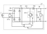
- FIG. 18 is a diagram showing an example of the configuration of an AC-DC converter 2 according to embodiment 6.
- the rectifier circuit 20 is composed of a single-phase H-bridge cell including two diodes 218a, 218b and two switching elements 220c, 220d.
- one leg is composed of a series circuit of diodes 218a, 218b, and the other leg is composed of a series circuit of switching elements 220c, 220d.
- the configuration and operation of the rectifier circuit 20 shown in FIG. 18 are publicly known, and further description will be omitted here.
- the control unit 6 generates switching signals for the two switching elements 220c, 220d using the control methods described in the first to third embodiments to drive them.
- the AC-DC converter 2 shown in FIG. 18 can achieve the same effects as those of the first to third embodiments.
- the control unit 6 generates switching signals for the two switching elements 220b, 220d using the control methods described in the first to third embodiments to drive them. This allows the AC-DC converter 2 shown in FIG. 19 to achieve the same effects as those in the first to third embodiments.
- the switching elements 220b and 220d are shown as IGBTs, but any elements capable of switching operation may be used.
- the AC-DC converter 2 shown in FIG. 19 is configured as a closed loop, but it may also be configured as an open loop. When the AC-DC converter 2 is configured as an open loop, the detection values of the voltage detectors 217a and 217b and the current detector 211 do not need to be used.
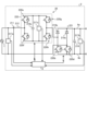
- Embodiment 8 In the eighth embodiment, a different example of the AC-DC converter 2 including the control unit 6 described in the first to third embodiments will be described. Components having the same or equivalent functions as those of the AC-DC converter 2 described in the first to third embodiments will be denoted by the same reference numerals, and a description of the overlapping contents will be omitted.
- FIG. 20 is a diagram showing an example of the configuration of an AC-DC converter 2 according to embodiment 8.
- the rectifier circuit 20 is composed of a single-phase H-bridge cell including two diodes 218a, 218b, four switching elements 220a, 220b, 220c, 220d, a capacitor 216b, and a voltage detector 217c.
- the voltage detector 217c may be provided outside the rectifier circuit 20.
- the capacitor 216 is shown as capacitor 216a.
- one leg is composed of a series circuit of diodes 218a and 218b, and the other leg is composed of a series circuit of switching elements 220a, 220b, 220c, and 220d.
- the capacitor 216b is connected between the connection point of the switching elements 220a and 220b and the connection point of the switching elements 220c and 220d.
- the voltage detection unit 217c detects the voltage of the capacitor 216b and outputs the detection value to the control unit 6.
- the control unit 6 generates a switching signal for controlling the switching elements 220a, 220b, 220c, and 220d based on the detection values of the voltage detection units 217a, 217b, and 217c and the current detection unit 211.
- the configuration and operation of the rectifier circuit 20 shown in FIG. 20 are publicly known, and further description will be omitted here.
- the control unit 6 generates switching signals for the four switching elements 220a, 220b, 220c, and 220d using the control methods described in the first to third embodiments to drive them.
- the AC-DC converter 2 shown in FIG. 20 can achieve the same effects as those in the first to third embodiments.
- the switching elements 220a, 220b, 220c, and 220d are shown as IGBTs, but any elements capable of switching operation may be used.
- the AC-DC converter 2 shown in FIG. 20 is configured as a closed loop, but it may also be configured as an open loop. When the AC-DC converter 2 is configured as an open loop, the detection values of the voltage detectors 217a, 217b, and 217c and the current detector 211 do not need to be used.
- Embodiment 9 a different example of the AC-DC converter 2 including the control unit 6 described in the first to third embodiments will be described. Components having the same or equivalent functions as those of the AC-DC converter 2 described in the first to third embodiments will be denoted by the same reference numerals, and a description of the overlapping contents will be omitted.
- FIG. 21 is a diagram showing an example of the configuration of an AC-DC converter 2 according to embodiment 9.
- the rectifier circuit 20 is composed of a single-phase H-bridge cell 221 and a switching cell 222.
- the single-phase H-bridge cell 221 includes two diodes 218a and 218c and two switching elements 220b and 220d.
- the switching cell 222 includes four switching elements 220e, 220f, 220g, and 220h, a capacitor 216c, and a voltage detection unit 217c.
- the voltage detection unit 217c may be provided outside the switching cell 222.
- diodes 218a and 218c are arranged in the upper arms of the two legs, and switching elements 220b and 220d are arranged in the lower arms of the two legs.
- switching cell 222 shown in FIG. 21 four switching elements 220e, 220f, 220g, and 220h are bridge-connected.
- the capacitor 216c is connected in parallel to the first leg consisting of the switching elements 220e and 220f and the second leg consisting of the switching elements 220g and 220h.
- the voltage detection unit 217c detects the voltage of the capacitor 216c and outputs the detection value to the control unit 6.
- the control unit 6 generates switching signals for controlling the switching elements 220b, 220d, 220e, 220f, 220g, and 220h based on the detection values of the voltage detection units 217a, 217b, and 217c and the current detection unit 211. Note that the configuration and operation of the rectifier circuit 20 shown in FIG. 21 are publicly known, and further explanation will be omitted here.
- the control unit 6 generates switching signals for the six switching elements 220b, 220d, 220e, 220f, 220g, and 220h using the control methods described in the first to third embodiments. This allows the AC-DC converter 2 shown in FIG. 21 to achieve the same effects as those in the first to third embodiments.
- switching elements 220b, 220d, 220e, 220f, 220g, and 220h are shown as IGBTs, but any elements capable of switching operation may be used.
- the AC-DC converter 2 shown in FIG. 21 is configured as a closed loop, it may also be configured as an open loop. When the AC-DC converter 2 is configured as an open loop, the detection values of voltage detectors 217a, 217b, and 217c and current detector 211 do not need to be used.
- Embodiment 10 In the tenth embodiment, a different example of the AC-DC converter 2 including the control unit 6 described in the first to third embodiments will be described. Components having the same or equivalent functions as those of the AC-DC converter 2 described in the first to third embodiments will be denoted by the same reference numerals, and a description of the overlapping contents will be omitted.
- FIG. 22 is a diagram showing an example of the configuration of an AC-DC converter 2 according to embodiment 10.
- the rectifier circuit 20 is composed of a single-phase diode bridge cell 213a and a switching cell 225.
- the switching cell 225 includes a single-phase diode bridge cell 213b and a series circuit made up of two switching elements 220a and 220b.
- the series circuit is connected in parallel to the single-phase diode bridge cell 213b.
- the capacitor 216 in FIG. 2 is replaced with two capacitors 216a and 216b connected in series.
- the series-connected capacitors 216a and 216b are connected between the DC buses 9a and 9b.
- the control unit 6 generates switching signals for controlling the switching elements 220a and 220b based on the detection values of the voltage detection units 217a and 217b and the current detection unit 211. Note that the configuration and operation of the rectifier circuit 20 shown in FIG. 22 are publicly known, and further explanation will be omitted here.
- the control unit 6 generates switching signals for the two switching elements 220a, 220b using the control methods described in the first to third embodiments to drive them.
- the AC-DC converter 2 shown in FIG. 22 can achieve the same effects as those in the first to third embodiments.
- the switching elements 220a and 220b are shown as IGBTs, but any elements capable of switching operation may be used.
- the AC-DC converter 2 shown in FIG. 22 is configured as a closed loop, but it may also be configured as an open loop. When the AC-DC converter 2 is configured as an open loop, it is not necessary to use the detection values of the voltage detectors 217a and 217b and the current detector 211.
Landscapes
- Engineering & Computer Science (AREA)
- Power Engineering (AREA)
- Rectifiers (AREA)
Priority Applications (2)
| Application Number | Priority Date | Filing Date | Title |
|---|---|---|---|
| JP2025566164A JPWO2025141868A1 (https=) | 2023-12-28 | 2023-12-28 | |
| PCT/JP2023/047279 WO2025141868A1 (ja) | 2023-12-28 | 2023-12-28 | 交流直流変換装置、回転機駆動装置及び冷凍サイクル適用機器 |
Applications Claiming Priority (1)
| Application Number | Priority Date | Filing Date | Title |
|---|---|---|---|
| PCT/JP2023/047279 WO2025141868A1 (ja) | 2023-12-28 | 2023-12-28 | 交流直流変換装置、回転機駆動装置及び冷凍サイクル適用機器 |
Publications (1)
| Publication Number | Publication Date |
|---|---|
| WO2025141868A1 true WO2025141868A1 (ja) | 2025-07-03 |
Family
ID=96217186
Family Applications (1)
| Application Number | Title | Priority Date | Filing Date |
|---|---|---|---|
| PCT/JP2023/047279 Pending WO2025141868A1 (ja) | 2023-12-28 | 2023-12-28 | 交流直流変換装置、回転機駆動装置及び冷凍サイクル適用機器 |
Country Status (2)
| Country | Link |
|---|---|
| JP (1) | JPWO2025141868A1 (https=) |
| WO (1) | WO2025141868A1 (https=) |
Citations (3)
| Publication number | Priority date | Publication date | Assignee | Title |
|---|---|---|---|---|
| JP2013150458A (ja) * | 2012-01-19 | 2013-08-01 | Daihen Corp | 電力変換回路の制御回路、この制御回路を用いた系統連系インバータシステムおよび単相pwmコンバータシステム |
| JP2016010210A (ja) * | 2014-06-24 | 2016-01-18 | パナソニックIpマネジメント株式会社 | 直流電源装置およびインバータ駆動装置およびこれを用いた空気調和機 |
| JP2017184365A (ja) * | 2016-03-29 | 2017-10-05 | 日立ジョンソンコントロールズ空調株式会社 | 電力変換装置、モータ駆動装置及びそれを用いた冷凍機器 |
-
2023
- 2023-12-28 WO PCT/JP2023/047279 patent/WO2025141868A1/ja active Pending
- 2023-12-28 JP JP2025566164A patent/JPWO2025141868A1/ja active Pending
Patent Citations (3)
| Publication number | Priority date | Publication date | Assignee | Title |
|---|---|---|---|---|
| JP2013150458A (ja) * | 2012-01-19 | 2013-08-01 | Daihen Corp | 電力変換回路の制御回路、この制御回路を用いた系統連系インバータシステムおよび単相pwmコンバータシステム |
| JP2016010210A (ja) * | 2014-06-24 | 2016-01-18 | パナソニックIpマネジメント株式会社 | 直流電源装置およびインバータ駆動装置およびこれを用いた空気調和機 |
| JP2017184365A (ja) * | 2016-03-29 | 2017-10-05 | 日立ジョンソンコントロールズ空調株式会社 | 電力変換装置、モータ駆動装置及びそれを用いた冷凍機器 |
Also Published As
| Publication number | Publication date |
|---|---|
| JPWO2025141868A1 (https=) | 2025-07-03 |
Similar Documents
| Publication | Publication Date | Title |
|---|---|---|
| JP5558530B2 (ja) | モーター駆動制御装置、圧縮機、送風機、空気調和機及び冷蔵庫又は冷凍庫 | |
| EP2309635B1 (en) | Ac-dc converter, ac-dc converter control method, motor driving device, compressor driving device, air conditioner, and heat pump-type hot-water supply device | |
| EP2667501B1 (en) | Power conversion apparatus | |
| EP3358732B1 (en) | Power conversion device and air-conditioning device using same | |
| JP5907712B2 (ja) | モータ駆動装置、およびこれを用いた機器 | |
| US20160087547A1 (en) | Power conversion device, motor drive control device equipped with power conversion device, compressor and blower equipped with motor drive control device, and air conditioner equipped with compressor or blower | |
| US7113414B2 (en) | Inverter control device for driving a motor and an air conditioner | |
| WO2010023978A1 (ja) | コンバータ回路、並びにそれを備えたモータ駆動制御装置、空気調和機、冷蔵庫、及び誘導加熱調理器 | |
| WO2016035209A1 (ja) | 電力変換装置及び冷凍サイクル装置 | |
| WO2012032910A1 (ja) | 電力変換装置、モータ駆動機器、冷凍空調機器 | |
| WO2022149206A1 (ja) | 電力変換装置、モータ駆動装置及び冷凍サイクル適用機器 | |
| KR20080014003A (ko) | 냉각 시스템용 가변속 드라이브 | |
| US20240128912A1 (en) | Power converter, motor driving apparatus, and air conditioner | |
| JP7507894B2 (ja) | 電力変換装置、モータ駆動装置及び冷凍サイクル適用機器 | |
| WO2025141868A1 (ja) | 交流直流変換装置、回転機駆動装置及び冷凍サイクル適用機器 | |
| JP7625158B1 (ja) | 交流直流変換装置、回転機駆動装置及び冷凍サイクル適用機器 | |
| JP7603907B1 (ja) | 交流直流変換装置、回転機駆動装置及び冷凍サイクル適用機器 | |
| WO2025141871A1 (ja) | 交流直流変換装置、回転機駆動装置及び冷凍サイクル適用機器 | |
| Endo et al. | Power electronics technology applied in inverter air conditioners | |
| WO2025141870A1 (ja) | 交流直流変換装置、回転機駆動装置及び冷凍サイクル適用機器 | |
| JP7603906B1 (ja) | 交流直流変換装置、回転機駆動装置及び冷凍サイクル適用機器 | |
| JP7592188B2 (ja) | 電力変換装置、モータ駆動装置および冷凍サイクル適用機器 | |
| WO2025141872A1 (ja) | 交流直流変換装置、回転機駆動装置及び冷凍サイクル適用機器 | |
| WO2025141865A1 (ja) | 交流直流変換装置、回転機駆動装置及び冷凍サイクル適用機器 | |
| WO2025141866A1 (ja) | 交流直流変換装置、回転機駆動装置及び冷凍サイクル適用機器 |
Legal Events
| Date | Code | Title | Description |
|---|---|---|---|
| 121 | Ep: the epo has been informed by wipo that ep was designated in this application |
Ref document number: 23963213 Country of ref document: EP Kind code of ref document: A1 |
|
| ENP | Entry into the national phase |
Ref document number: 2025566164 Country of ref document: JP Kind code of ref document: A |
|
| WWE | Wipo information: entry into national phase |
Ref document number: 2025566164 Country of ref document: JP |