WO2025134685A1 - 電源装置及び電源装置用電源ケース並びに電源装置の製造方法 - Google Patents
電源装置及び電源装置用電源ケース並びに電源装置の製造方法 Download PDFInfo
- Publication number
- WO2025134685A1 WO2025134685A1 PCT/JP2024/041497 JP2024041497W WO2025134685A1 WO 2025134685 A1 WO2025134685 A1 WO 2025134685A1 JP 2024041497 W JP2024041497 W JP 2024041497W WO 2025134685 A1 WO2025134685 A1 WO 2025134685A1
- Authority
- WO
- WIPO (PCT)
- Prior art keywords
- power supply
- supply device
- case body
- case
- battery modules
- Prior art date
- Legal status (The legal status is an assumption and is not a legal conclusion. Google has not performed a legal analysis and makes no representation as to the accuracy of the status listed.)
- Pending
Links
Images



Classifications
-
- H—ELECTRICITY
- H01—ELECTRIC ELEMENTS
- H01M—PROCESSES OR MEANS, e.g. BATTERIES, FOR THE DIRECT CONVERSION OF CHEMICAL ENERGY INTO ELECTRICAL ENERGY
- H01M50/00—Constructional details or processes of manufacture of the non-active parts of electrochemical cells other than fuel cells, e.g. hybrid cells
- H01M50/20—Mountings; Secondary casings or frames; Racks, modules or packs; Suspension devices; Shock absorbers; Transport or carrying devices; Holders
- H01M50/204—Racks, modules or packs for multiple batteries or multiple cells
- H01M50/207—Racks, modules or packs for multiple batteries or multiple cells characterised by their shape
- H01M50/213—Racks, modules or packs for multiple batteries or multiple cells characterised by their shape adapted for cells having curved cross-section, e.g. round or elliptic
-
- H—ELECTRICITY
- H01—ELECTRIC ELEMENTS
- H01M—PROCESSES OR MEANS, e.g. BATTERIES, FOR THE DIRECT CONVERSION OF CHEMICAL ENERGY INTO ELECTRICAL ENERGY
- H01M50/00—Constructional details or processes of manufacture of the non-active parts of electrochemical cells other than fuel cells, e.g. hybrid cells
- H01M50/20—Mountings; Secondary casings or frames; Racks, modules or packs; Suspension devices; Shock absorbers; Transport or carrying devices; Holders
- H01M50/233—Mountings; Secondary casings or frames; Racks, modules or packs; Suspension devices; Shock absorbers; Transport or carrying devices; Holders characterised by physical properties of casings or racks, e.g. dimensions
-
- H—ELECTRICITY
- H01—ELECTRIC ELEMENTS
- H01M—PROCESSES OR MEANS, e.g. BATTERIES, FOR THE DIRECT CONVERSION OF CHEMICAL ENERGY INTO ELECTRICAL ENERGY
- H01M50/00—Constructional details or processes of manufacture of the non-active parts of electrochemical cells other than fuel cells, e.g. hybrid cells
- H01M50/20—Mountings; Secondary casings or frames; Racks, modules or packs; Suspension devices; Shock absorbers; Transport or carrying devices; Holders
- H01M50/251—Mountings; Secondary casings or frames; Racks, modules or packs; Suspension devices; Shock absorbers; Transport or carrying devices; Holders specially adapted for stationary devices, e.g. power plant buffering or backup power supplies
-
- H—ELECTRICITY
- H01—ELECTRIC ELEMENTS
- H01M—PROCESSES OR MEANS, e.g. BATTERIES, FOR THE DIRECT CONVERSION OF CHEMICAL ENERGY INTO ELECTRICAL ENERGY
- H01M50/00—Constructional details or processes of manufacture of the non-active parts of electrochemical cells other than fuel cells, e.g. hybrid cells
- H01M50/20—Mountings; Secondary casings or frames; Racks, modules or packs; Suspension devices; Shock absorbers; Transport or carrying devices; Holders
- H01M50/267—Mountings; Secondary casings or frames; Racks, modules or packs; Suspension devices; Shock absorbers; Transport or carrying devices; Holders having means for adapting to batteries or cells of different types or different sizes
-
- H—ELECTRICITY
- H01—ELECTRIC ELEMENTS
- H01M—PROCESSES OR MEANS, e.g. BATTERIES, FOR THE DIRECT CONVERSION OF CHEMICAL ENERGY INTO ELECTRICAL ENERGY
- H01M50/00—Constructional details or processes of manufacture of the non-active parts of electrochemical cells other than fuel cells, e.g. hybrid cells
- H01M50/20—Mountings; Secondary casings or frames; Racks, modules or packs; Suspension devices; Shock absorbers; Transport or carrying devices; Holders
- H01M50/271—Lids or covers for the racks or secondary casings
-
- H—ELECTRICITY
- H01—ELECTRIC ELEMENTS
- H01M—PROCESSES OR MEANS, e.g. BATTERIES, FOR THE DIRECT CONVERSION OF CHEMICAL ENERGY INTO ELECTRICAL ENERGY
- H01M50/00—Constructional details or processes of manufacture of the non-active parts of electrochemical cells other than fuel cells, e.g. hybrid cells
- H01M50/20—Mountings; Secondary casings or frames; Racks, modules or packs; Suspension devices; Shock absorbers; Transport or carrying devices; Holders
- H01M50/284—Mountings; Secondary casings or frames; Racks, modules or packs; Suspension devices; Shock absorbers; Transport or carrying devices; Holders with incorporated circuit boards, e.g. printed circuit boards [PCB]
-
- H—ELECTRICITY
- H01—ELECTRIC ELEMENTS
- H01M—PROCESSES OR MEANS, e.g. BATTERIES, FOR THE DIRECT CONVERSION OF CHEMICAL ENERGY INTO ELECTRICAL ENERGY
- H01M50/00—Constructional details or processes of manufacture of the non-active parts of electrochemical cells other than fuel cells, e.g. hybrid cells
- H01M50/20—Mountings; Secondary casings or frames; Racks, modules or packs; Suspension devices; Shock absorbers; Transport or carrying devices; Holders
- H01M50/289—Mountings; Secondary casings or frames; Racks, modules or packs; Suspension devices; Shock absorbers; Transport or carrying devices; Holders characterised by spacing elements or positioning means within frames, racks or packs
- H01M50/291—Mountings; Secondary casings or frames; Racks, modules or packs; Suspension devices; Shock absorbers; Transport or carrying devices; Holders characterised by spacing elements or positioning means within frames, racks or packs characterised by their shape
-
- Y—GENERAL TAGGING OF NEW TECHNOLOGICAL DEVELOPMENTS; GENERAL TAGGING OF CROSS-SECTIONAL TECHNOLOGIES SPANNING OVER SEVERAL SECTIONS OF THE IPC; TECHNICAL SUBJECTS COVERED BY FORMER USPC CROSS-REFERENCE ART COLLECTIONS [XRACs] AND DIGESTS
- Y02—TECHNOLOGIES OR APPLICATIONS FOR MITIGATION OR ADAPTATION AGAINST CLIMATE CHANGE
- Y02E—REDUCTION OF GREENHOUSE GAS [GHG] EMISSIONS, RELATED TO ENERGY GENERATION, TRANSMISSION OR DISTRIBUTION
- Y02E60/00—Enabling technologies; Technologies with a potential or indirect contribution to GHG emissions mitigation
- Y02E60/10—Energy storage using batteries
Definitions
- This disclosure relates to a power supply device, a power supply case for the power supply device, and a method for manufacturing the power supply device.
- Battery modules which are made up of multiple rechargeable secondary battery cells such as lithium-ion secondary batteries connected in series or parallel, are used in various fields as power supplies to drive the devices they are intended to drive.
- backup power supplies are used in which multiple battery modules, each made up of multiple secondary battery cells connected in series or parallel, are inserted into a rack.
- Backup power supplies for data centers consist of multiple battery modules, electrical components, and a power supply case. Each battery module is designed to be insertable and removable. The power supply also has an internal stopper to prevent interference between the battery modules and electrical components when the battery modules are inserted or removed.
- Such stoppers are used to position the battery module when it is inserted into the rack. Specifically, when the battery module is pushed into a specified position, the stoppers come into contact with the end face of the battery module to prevent it from being pushed in any further. This holds the battery module in a fixed position. In this state, the battery side connector provided on the end face of the battery module is fitted into the case side connector mounted on the circuit board located at the back of the power supply case, and the battery module is electrically connected to the circuit board of the power supply case.
- One objective of the present disclosure is to provide a power supply device that can accommodate variations in the longitudinal length of the battery module. Another objective is to provide a power supply device that can share a power supply case even when the battery modules have different lengths. Note that the description of these objectives and objectives of the present disclosure does not preclude the existence of other objectives and objectives. Furthermore, it is not necessary for one aspect of the present disclosure to solve all of these objectives. Furthermore, it is possible to extract other objectives from the description of the specification, drawings, and claims of the present disclosure.
- the power supply device includes a plurality of battery modules each having a plurality of secondary battery cells, and a power supply case that houses the plurality of battery modules.
- the power supply case includes a case body having a first surface with a plurality of insertion/removal openings that respectively store the plurality of battery modules in an insertable/removable state, a second surface that faces the first surface, and a plate portion that is fixed to a part of the case body and is made of a separate member from the case body.
- the plate portion is provided with stopper portions that interfere with the end surfaces of the plurality of battery modules when the plurality of battery modules are inserted from each of the end surface sides of the plurality of battery modules toward the second surface side from each of the insertion/removal openings of the case body, thereby regulating the amount of insertion.
- a power supply case is a power supply case for a power supply device for storing a plurality of battery modules each having a plurality of secondary battery cells connected thereto, and includes a case body having a first surface with a plurality of insertion/removal openings for respectively storing the plurality of battery modules in an insertable/removable state, a second surface facing the first surface, and a plate portion fixed to a part of the case body and made of a separate member from the case body.
- the plate portion has stopper portions that interfere with the end faces of the battery modules when the plurality of battery modules are inserted from each end face side toward the second surface side from each insertion/removal opening of the case body, thereby regulating the amount of insertion.
- a method for manufacturing a power supply device is a method for manufacturing a power supply device including a plurality of battery modules each having a plurality of secondary battery cells, and a power supply case that houses the plurality of battery modules.
- the power supply case includes a case body having a first surface with a plurality of insertion/removal openings that respectively store the plurality of battery modules in an insertable/removable state, and a second surface opposite the first surface, and a plate portion that is fixed to a part of the case body and is made of a separate member from the case body.
- the manufacturing method includes a step of preparing the plate portion that has a stopper portion that restricts the amount of insertion by interfering with the end faces of the battery modules when the plurality of battery modules are inserted from each end face side of the plurality of battery modules toward the second face side from each insertion/removal opening of the case body, and a step of fixing the plate portion to a part of the case body.
- the plate portion with the stopper portion is made of a separate member from the case body, so that even if the length of the battery module to be inserted is changed, it is possible to deal with this by simply replacing the plate portion with the position of the stopper portion changed accordingly, thereby avoiding the need to redesign the case body.
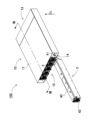
- FIG. 1 is an exploded perspective view showing a state in which one battery module is inserted into or removed from a power supply device according to a first embodiment.
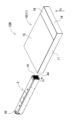
- FIG. 2 is an exploded perspective view of the power supply device of FIG. 1 as viewed from the rear side.
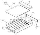
- 3 is an exploded perspective view of a power supply case of the power supply device of FIG. 1.
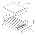
- FIG. 4 is an exploded perspective view of the power supply case of FIG. 3 as viewed from the rear side.
- FIG. 5 is an exploded perspective view of the power supply case of FIG. 4 with the circuit board and insulating sheet removed.
- FIG. 6 is an enlarged perspective view of the power supply case of FIG.
- FIG. 7 is an exploded perspective view of the power supply case of FIG. 5 with the plate portion removed.
- FIG. 8 is a vertical cross-sectional view of the power supply device of FIG. 1 taken along line VIII-VIII.
- 9 is an exploded perspective view of the battery module of FIG. 1.
- FIG. FIG. 10 is a schematic cross-sectional view of the power supply device according to the first embodiment.
- FIG. 11 is a schematic cross-sectional view showing a state in which battery modules of different lengths are inserted into the case body of FIG.
- FIG. 12 is an exploded perspective view of a power supply device according to a comparative example, as viewed from the rear side.
- FIG. 13 is an enlarged perspective view showing a stopper portion of a power supply device according to a comparative example.
- FIG. 14 is a schematic cross-sectional view showing a state in which a battery module is inserted into a power supply case in a power supply device according to a comparative example.
- FIG. 15 is a schematic cross-sectional view showing a state in which the battery module in the power supply device of FIG. 14 is elongated.
- FIG. 16 is a schematic cross-sectional view showing a power supply device according to a modified example.
- FIG. 17 is a perspective view of the plate portion.
- FIG. 18 is a perspective view showing a plate portion of the power supply device according to the second embodiment.
- FIG. 19 is a perspective view showing a plate portion of a power supply device according to the third embodiment.
- the case body has a plurality of storage spaces formed therein, each of which is connected to the plurality of insertion/removal openings and which respectively houses the plurality of battery modules.
- the end face of the plate portion is not exposed above the bottom face of each storage space.
- the mounting surface of the case body on which the plurality of battery modules are placed and the upper surface of the plate portion are formed on the same plane on the inner surface of the case body.
- the case body has a bottom opening formed by opening a portion of the bottom surface thereof, and the plate portion is positioned so as to close the bottom opening.
- the power supply device further includes a circuit board disposed inside the case body between the end faces of the plurality of battery modules and the second surface, and the plate portion is provided with a plate-side board fixing portion for fixing a portion of the circuit board.
- the case body is provided with a case side board fixing portion for fixing another part of the circuit board.
- the circuit board is placed in the case body in a position that is aligned with the insertion direction of the battery module. With the above configuration, the circuit board can be held in a horizontal position between the battery module and the second surface of the case body.
- the case body has the multiple insertion/removal openings open side-by-side on the first surface.
- the stopper portion is formed in a semicircular shape in cross section in any of the above embodiments.
- the power supply device is a backup power supply for a data center.
- the aperture size of the battery module etc. is regulated by standards, so in order to increase the capacity by making the battery module larger, it can only be extended in the depth direction.
- the power supply case itself, including the stopper portion must be redesigned.
- this can be addressed while keeping the case body common.
- the step of preparing the plate portion includes a step of determining the plate length D1 in the depth direction of the plate portion such that D1 > Lmax - Lmin, where Lmax is the expected maximum value of the module length of the battery module and Lmin is the expected minimum value of the module length of the battery module.
- the power supply device disclosed herein can be used as a stationary power supply device, for example, a backup power supply for a data center, a home, business, or factory power storage device that stores electricity generated by solar power generation or the like, or a power supply for daytime peak cutting.
- a power supply device used as a backup power supply for a data center is described. Power supplies for data centers are used by being inserted into storage spaces such as racks, in the same way as hardware such as servers, storage, and network switches. Such power supplies mounted in racks are also called power shelves, etc.
- FIGS. 7 is an exploded perspective view of the power supply case 10 of FIG. 5 with the circuit board 30 and the insulating sheet 34 removed from it;
- FIG. 8 is a vertical cross-sectional view of the power supply device 100 of FIG. 1 taken along line VIII-VIII;
- FIG. 9 is an exploded perspective view of the battery module 2 of FIG. 1;
- FIG. 10 is a schematic cross-sectional view of the power supply device 100 of embodiment 1;
- FIG. 11 is a schematic cross-sectional view of a state in which battery modules 2′ of different lengths are inserted into the case body 11 of FIG. 10.
- the power supply device 100 shown in these figures comprises a power supply case 10 and a battery module 2.
- a circuit board 30 is disposed on the rear side of the power supply case 10.
- the power supply case 10 is a member for housing one or more battery modules 2 so as to be freely insertable and removable, and constitutes the external shape of the power supply device 100.
- the power supply case 10 is composed of a case body 11 having a box-shaped external shape, and has a first surface 12 and a second surface 13 which is the opposing surface.
- the front side of the case body 11 is the first surface 12, and the back side is the second surface 13.
- the first surface 12 has insertion/removal openings 14 for inserting and removing the battery modules 2.
- the external shape of the case body 11 of the power supply case 10 is flat, the insertion/removal openings 14 are arranged horizontally on the first surface 12 on the front side, and multiple battery modules 2 are arranged side by side.
- the case body 11 is divided into four parts: a first body case 15, a second body case 16, a third body case 17, and a fourth body case 18.
- the first body case 15 and the second body case 16 form a lid, and the first body case 15 and the second body case 16 close the top of the third case, which is bent into a U-shape so that the top is open.
- the second surface 13, which is the back surface of the case body 11, is closed and mounted on the fourth body case 18.
- multiple partition plates 19 are fixed parallel to each other and spaced apart inside the case body 11 to define multiple storage spaces 3.
- Each storage space 3 is connected through an insertion/removal opening 14 and stores a battery module 2.
- multiple partition plates 19 are shown fixed to the bottom surface of the third body case 17, but it goes without saying that multiple partition plates 19 may be fixed to the first body case 15 instead of or in addition to the third body case 17.
- the second body case 16 is constructed separately from the first body case 15 so that the circuit board 30 and the plate portion 20 can be easily accessed when the multiple partition plates 19 are fixed to the first body case 15 and the third body case 17.
- circuit board 30 Furthermore, a circuit board 30 is disposed on the rear side of the case body 11, between the second surface 13 and the battery module 2. The circuit board 30 is placed inside the case body 11 in a position aligned with the insertion direction of the battery module 2. That is, the circuit board 30 is held in a horizontal position between the battery module 2 and the second surface 13.
- the circuit board 30 is equipped with electronic circuits such as a current detection circuit that detects charging and discharging currents, a circuit that detects and calculates the full charge and remaining capacity of the secondary battery cells from battery information such as the voltage and temperature of the secondary battery cells input from the battery side circuit boards of the battery blocks each having multiple secondary battery cells connected to each other, a control circuit that controls the charging and discharging of the secondary battery cells, and a protection circuit that monitors whether the battery is normal.
- the circuit board 30 is formed in a rectangular shape. In the example shown in Figure 4, the circuit board 30 is fixed in a horizontal position on the back side of the power supply case 10. This circuit board 30 is preferably made of a resin such as glass epoxy.
- an insulating sheet 34 may be interposed as shown in FIG. 5. This can improve the insulation on the back side of the circuit board 30.
- the power supply case is not limited to the above-mentioned form, and the insertion/removal openings may be stacked vertically on the case body so that the housing parts are arranged vertically.
- the housing parts may also be arranged in a checkerboard pattern. It is not necessary to insert housing parts into all of the insertion/removal openings 14 of the power supply case 10, and the number of housing parts to be inserted into the power supply case may be set according to the output and capacity required of the power supply device.
- the shape and length of the opening end of the insertion/removal opening are designed according to the size of the battery module to be inserted or removed.
- the case body 11 is made of metal such as sheet metal with excellent heat dissipation properties.
- the battery module 2 is inserted into and removed from the insertion/removal opening 14 of the case body 11.
- the external shape of the battery module 2 is formed into a rod shape extending in one direction so as to facilitate insertion and removal.
- the rod-shaped battery module 2 is preferably formed into a box shape.
- One end face of the box-shaped battery module 2 in the longitudinal direction DL is an insertion face 41 through which each housing is inserted into the case body 11.
- the other end face is an exposed face 42 that is exposed from the case body 11 in a state where the battery module is inserted into the case body 11.
- the battery module is formed into a prism shape with a square end face.
- the shape of the battery module is not limited to this, and the end face may be rectangular, octagonal, or the like.
- each battery module 2 houses multiple secondary battery cells 1 in a box-shaped module housing 43.
- Each battery module 2 outputs an output, which is generated by connecting multiple secondary battery cells 1 housed therein in series or parallel, to the power supply case 10.
- the battery module 2 is provided with a battery side connector 44 for connecting to the power supply case 10.
- the case body 11 is also provided with a case side connector 32 that connects to the battery side connector 44.
- the battery side connector 44 is provided on the insertion surface 41 side of the battery module 2.
- the case side connector 32 is provided on the circuit board 30 in a position facing the insertion surface 41 of the battery module 2.
- the battery side connector 44 and the case side connector 32 are positioned so that when the battery module 2 is inserted into the case body 11 and the insertion surface 41 comes into contact with a stopper portion 21 (described below) and stops in a position, the battery side connector 44 engages with the case side connector 32.
- the module housing 43 of the battery module 2 is formed in a box shape that extends in the front-rear direction, and has an assembly storage space for the internal assembly 45 inside.
- This module housing 43 is composed of a first module case 43A that is U-shaped in cross section and has an open bottom, and a second module case 43B that closes the bottom of the first module case 43A.
- These first module case 43A and second module case 43B are formed into a predetermined shape by bending a metal plate, for example.
- a metal plate for example, hot-dip galvanized steel plate, aluminum, or an aluminum alloy can be used.
- the assembly storage space inside the module housing 43 also contains an internal assembly 45.
- the internal assembly 45 contains a battery block including multiple secondary battery cells 1 and an output unit including an output terminal.
- the battery block contains, for example, multiple cylindrical secondary battery cells 1 arranged vertically and parallel to each other in a battery holder.
- the battery holder is preferably made of a material with excellent insulating and heat resistance, for example, a resin such as polycarbonate or ABS.
- the multiple secondary battery cells 1 are connected in parallel and in series.
- the secondary battery cells 1 are lithium ion secondary batteries.
- a battery module 2 in which the secondary battery cells 1 are lithium ion secondary batteries can have a large output relative to its volume and weight.
- lithium ion batteries instead of lithium ion batteries, lithium polymer batteries and nickel metal hydride batteries can also be used for the secondary battery cells. Therefore, the present disclosure does not specify that the secondary battery cells are lithium ion batteries, and any battery that can be charged can be used for the secondary battery cells.
- the battery block has a module board arranged in a vertical position on the side of the battery holder, and lead plates 46 connected to the end electrodes of the secondary battery cells 1 are connected to the module housing 43 to detect the intermediate potential of the secondary battery cells 1 connected to each other in series.
- the module housing 43 is equipped with an electronic circuit that detects the state of the multiple secondary battery cells 1. This electronic circuit includes a voltage detection circuit that detects the total potential and intermediate potential of the battery assembly in which the secondary battery cells 1 are connected in series or parallel, and a circuit that detects the temperature of the multiple secondary battery cells 1.
- the power supply case 10 includes a plate portion 20 that is fixed to a part of the case body 11 and is made of a separate member from the case body 11.
- the plate portion 20 is provided with stopper portions 21 that interfere with or come into contact with the end faces (insertion faces 41) of the battery modules 2 when the battery modules 2 are inserted from the respective end faces (insertion faces 41) of the case body 11 toward the second face 13 side from the respective insertion/removal openings 14 of the case body 11, thereby restricting the amount of insertion.
- the plate portion 20 provided with the stopper portions 21 out of a separate member from the case body 11, even if the module length of the battery module 2' to be inserted is changed from L1 in FIG. 10 to L2 in FIG. 11, it is possible to deal with this by preparing a plate portion 20' in which the position of the stopper portions 21' is changed accordingly, and it is possible to avoid a situation in which the case body 11 needs to be redesigned.
- the power supply device 600 for a data center is composed of a power supply case 610, a plurality of battery modules 602 that are inserted into and removed from the power supply case 610, and electrical components 630.
- the battery modules 602 are detachable and replaceable.
- a stopper portion is provided on the power supply case 610 so that the battery modules 602 and the electrical components 630 do not interfere with each other when the battery modules 602 are inserted or removed.
- the stopper portion is provided to position the insertion margin of the battery modules 602, and is also called a ring stopper or the like.
- a pin-shaped stopper portion 721 is used.
- such stopper portion 821 is used to position the battery module 802 when it is inserted into the power supply case 810. Specifically, when the battery module 802 is pushed into a specified position, the stopper portion 821 abuts against the end face of the battery module 802 so that the battery module 802 cannot be pushed in any further. This holds the battery module 802 in a fixed position. In this state, the battery side connector 844 provided on the end face of the battery module 802 is fitted into the case side connector 832 mounted on the circuit board 830 located at the back of the power supply case 810, and the battery module 802 is electrically connected to the circuit board 830 of the power supply case 810.
- Such power supplies for data centers are inserted into storage spaces such as racks before use.
- equipment used for data centers and other purposes to have hardware such as servers, storage, and network switches, including power supplies, that are standardized products.
- six battery modules used for backup purposes are mounted inside a power supply unit located in the center of the rack.
- OUs open units
- 1 OU is 1.89 inches (48 mm) and its width is 21 inches (533.4 mm).
- the power supply device 800 shown in FIG. 14 consider an example in which a battery module 902 with a total length of L2, which is longer than the module length L1 in FIG. 14, is set in the power supply case 910 as in the power supply device 900 shown in FIG. 15 in order to increase the capacity of the battery module 802.
- the board length of the circuit board 930 constituting the electrical equipment section is accordingly reduced from B1 to B2.
- the position of the stopper portion 921 for positioning the battery module 902 in a fixed position within the power supply case 910 needs to be shifted to the left of the stopper portion 821 in FIG. 14.
- the position of the stopper portion is different inside, and so it was necessary to redesign it.
- the position of the stopper portion which determines the insertion position of the battery module, varies depending on the longitudinal length of the battery module, so it was not possible to standardize the design of the power supply case for potential modules with different longitudinal lengths.
- a stopper portion 21 is provided on the plate portion 20 which is made of a separate member from the case body 11.
- This allows the case body 11 to be adapted without redesigning it, even if the length of the battery module 2 to be inserted into the case body 11 is changed from L1 to L2, by replacing it with a plate portion 20 in which the position of the stopper portion 21 has been changed accordingly.
- This makes it possible to standardize the case body 11 for a wide variety of battery modules 2, thereby reducing manufacturing costs.
- the aperture size of battery modules, etc. is regulated by standards, so in order to increase the capacity of the battery module by making it larger, it can only be extended in the depth direction.
- the power supply case itself, including the stopper portion must be redesigned.
- the stopper portion 21 on the plate portion 20, which is a separate member this can be addressed while keeping the case body 11 common.
- the position where the stopper portion 21 is provided is determined according to the module length of the battery module 2. As shown in FIG. 10, the stopper portion 21 is provided at a position L1 from the first surface 12 of the case body 11 according to the module length L1 of the battery module 2. On the other hand, when the battery module 2' has a module length L2 as shown in FIG. 11, the stopper portion 21' is provided at a position L2 from the first surface 12 on the plate portion 20'.
- the plate length D1 in the depth direction of the plate portion 20, i.e., the longitudinal direction DL in which the battery module 2 is inserted is designed according to the expected module length of the battery module 2 so that the position where the stopper portion 21 is provided can be adjusted according to the module length of the battery module 2. Specifically, it is preferable to design the plate length so that D1>(maximum module length Lmax of the expected battery module)-(minimum module length Lmin of the expected battery module).
- the plate section 20 also has a plate-side board fixing section 22 for fixing a part of the circuit board 30.
- a plate-side board fixing section 22 for fixing a part of the circuit board 30.
- the case body 11 is provided with a case side board fixing portion 36 for fixing another part of the circuit board 30.
- the circuit board 30 is fixed to the case body 11 and the plate portion 20 by the case side board fixing portion 36 and the plate side board fixing portion 22.
- the case side board fixing portion 36 and the plate side board fixing portion 22 are each configured as a cylindrical spacer with a threaded groove on the inner surface, but the case side board fixing portion 36 and the plate side board fixing portion 22 are not limited to this, and any known configuration capable of fixing the circuit board 30 can be used as appropriate.
- the fixing position of the case side board fixing portion 36 is fixed near the second surface 13 of the case body 11, while the plate side board fixing portion 22 is determined according to the board length of the circuit board 30. That is, since the board length may change depending on the module length as described above, in order to avoid redesigning the case body 11 due to the change in the board length of the circuit board 30, the plate side board fixing portion 22 of the plate portion 20 is adjusted to accommodate this.
- the position of the plate side board fixing portion 22 on the plate portion 20 is designed so that the plate side board fixing portion 22 is provided at a position approximately B1 from the second surface 13 according to the board length B1 of the circuit board 30.
- FIG. 10 the position of the plate side board fixing portion 22 on the plate portion 20 is designed so that the plate side board fixing portion 22 is provided at a position approximately B1 from the second surface 13 according to the board length B1 of the circuit board 30.
- a bottom opening 24 is provided in part of the bottom surface of the case body 11.
- the plate portion 20 is positioned so as to close the bottom opening 24. This allows the plate portion 20 to be added to the case body 11 without causing any change in height due to the addition of the plate portion 20, and prevents the plate portion 20 from interfering when the battery module 2 is pushed in.
- the edge of the plate portion 20 can be provided with a locking piece 26 that partially locks with the edge of the case body 11, as shown in Figures 7, 17, etc. This makes it easier to align the bottom surface 3B of the storage space 3 and the top surface 120A of the plate portion 20 on the same plane. Furthermore, it is preferable to form the locking piece 26 thin and adjust the position of the locking piece 26 so as not to interfere with the insertion of the battery module 2.
- the stopper portion 21B provided on the plate portion 20B is formed in a hood shape with an opening on one side.
- the hood-shaped opening surface of this stopper portion 21B interferes with, i.e., abuts against, the insertion surface 41, which is the end surface of the battery module 2.
- This type of stopper portion 21B can also be easily formed by punching a metal plate. Note that the stopper portion 21B in Fig. 18 needs to be formed so that the hood-shaped opening surface faces the insertion surface 41 of the battery module 2. This is because if the stopper portion 21B is oriented in the opposite direction, it may not be possible to restrict the pushing of the battery module 2 along the inclined surface of the hood shape.
- the stopper portion 21C provided on the plate portion 20C is formed by making a U-shaped cut in the metal plate portion 20 and raising it.
- the stopper portion 21 of this configuration also has the advantage of being easily formed.
- the stopper portion 21C in FIG. 19 is also preferably formed in a position in which the cut is on the battery module 2 side. This is because, if it is in the opposite direction, there is a concern that the raised stopper portion 21 may be knocked down by pushing the battery module 2.
- each stopper portion 21C may be formed by rotating 90° in either direction from the state shown in FIG. 19. This avoids the concern that the edge of the stopper portion 21C may interfere with the insertion surface 41 of the battery module 2 and the stopper portion 21C may be bent in a direction in which it falls down when pushed.
- the plate portion 20 is formed from a metal plate. Metal plates are preferable because they are strong and easy to process. However, as shown in FIG. 7, etc., it is necessary to consider insulation with the circuit board 30 that is fixed to the upper surface 120A of the plate portion 20, and care must be taken, such as adding an insulating sheet 34.
- the power supply device 100 includes a plurality of battery modules 2 and a power supply case 10. Each of the plurality of battery modules 2 has a plurality of secondary battery cells connected thereto.
- the power supply case 10 includes a case body 11 and a plate portion 20.
- the case body 11 has a first surface 12 with a plurality of insertion/removal openings 14 that respectively accommodate the plurality of battery modules 2 in an insertable/removable state, and a second surface 13 that faces the first surface 12.
- the plate portion 20 is fixed to a part of the case body 11 and is formed of a separate member from the case body 11.
- a plate portion 20 is prepared that has stopper portions 21 that interfere with the insertion surface 41 of the battery modules 2 to regulate the amount of insertion when the battery modules 2 are inserted from each of the insertion openings 14 of the case body 11 toward the second surface 13 from each of the insertion surfaces 41 at the end faces.
- the plate portion 20 is fixed to a part of the case body 11. In this way, by configuring the plate portion 20 with the stopper portions 21 as a separate member from the case body 11, even if the length of the battery modules 2 to be inserted is changed, it can be accommodated by simply replacing the plate portion 20 with the position of the stopper portions 21 changed accordingly, and it is possible to avoid having to redesign the case body 11.
- the process of preparing the plate portion 20 can include a process of determining the plate length D1 in the depth direction of the plate portion 20 so that D1 > Lmax - Lmin, where Lmax is the maximum module length of the expected battery module 2 and Lmin is the minimum module length of the expected battery module. This makes it possible to change the position at which the stopper portion 21 is provided within the range of the plate length of the plate portion 20, thereby making it possible to accommodate the entire range of the expected module lengths of the battery module 2.
- the power supply device, power supply case for the power supply device, and method for manufacturing the power supply device according to the present disclosure can be suitably used as a stationary power storage device, such as a power supply device for home, business, or factory use, or as a backup power source for a data center, etc.
Landscapes
- Chemical & Material Sciences (AREA)
- Chemical Kinetics & Catalysis (AREA)
- Electrochemistry (AREA)
- General Chemical & Material Sciences (AREA)
- Battery Mounting, Suspending (AREA)
Abstract
電源装置は、複数の二次電池セルを接続した複数の電池モジュールと、電源ケースとを備える。電源ケースは、複数の電池モジュールを挿抜可能な状態にそれぞれ収納する複数の挿抜口を開口した第一面と、第一面と対向する第二面と、を有するケース本体と、ケース本体の一部に固定される、ケース本体と別部材で構成されたプレート部とを備える。プレート部は、複数の電池モジュールを各端面側からそれぞれ、ケース本体の各挿抜口から第二面側に向かって挿入する際に、該電池モジュールの端面と干渉することで押し込み量を規制するストッパ部を設けている。
Description
本開示は、電源装置及び電源装置用電源ケース並びに電源装置の製造方法に関する。
リチウムイオン二次電池等の充電可能な二次電池セルを複数、直列や並列に接続した電池モジュールは、駆動対象の機器を駆動させる電源装置として各分野で利用されている。例えば、二次電池セルを複数、直列や並列に接続した電池モジュールを複数本、ラックに挿入したバックアップ用電源装置が利用されている。
データセンター向けのバックアップ用電源装置は、複数の電池モジュールと、電装部品と、電源ケースとで構成される。各電池モジュールは、挿抜可能な構造となっている。また電源装置は、電池モジュールの抜き差しの際、電池モジュールと電装部品とが干渉しないように、内部にストッパ部が設けられている。
このようなストッパを用いて、電池モジュールをラックに挿入する際の、電池モジュールの位置決めを行っている。具体的には、電池モジュールを規定の位置まで押し込んだ状態で、それ以上電池モジュールを押し込めないように、ストッパが電池モジュールの端面と当接する。これにより、電池モジュールは定位置に保持される。またこの状態で、電源ケースの奥側に配置された回路基板上に実装されたケース側コネクタに、電池モジュールの端面に設けられた電池側コネクタが嵌合されて、電池モジュールは電源ケースの回路基板と電気的に接続される。
電源装置を構成する電池モジュールの高容量、高出力化が要求されている。しかしながら、より多くの二次電池セルを含めようとして電池モジュールを長大化すると、これに応じてストッパ部の位置を変更するように、電源ケースを設計し直す必要があった。特に電池モジュールの挿入しろの位置決めとなるストッパ部の位置は、電池モジュールの長手方向の長さによって変わるため、長手方向の長さが異なる電池モジュールに対して電源ケースの設計を共通化することができないという問題があった。
本開示の一の課題は、電池モジュールの長手方向の長さが変動しても対応可能な電源装置を提供することにある。また他の課題は、電池モジュールの長さが異なる場合でも電源ケースを共通化することが可能な電源装置を提供することにある。なお、本開示のこれらの目的や課題の記載は、他の目的や課題の存在を妨げるものではない。また本開示の一態様は、これらの課題の全てを解決する必要はないものとする。さらに本開示の明細書、図面、請求項の記載から、これら以外の課題を抽出することが可能である。
本開示の一形態に係る電源装置は、複数の二次電池セルをそれぞれ有する複数の電池モジュールと、前記複数の電池モジュールを収納する電源ケースとを備える。電源ケースは、前記複数の電池モジュールを挿抜可能な状態にそれぞれ収納する複数の挿抜口を開口した第一面と、前記第一面と対向する第二面と、を有するケース本体と、前記ケース本体の一部に固定される、前記ケース本体と別部材で構成されたプレート部とを備える。前記プレート部は、前記複数の電池モジュールを前記複数の電池モジュールの各端面側からそれぞれ、前記ケース本体の前記複数の挿抜口の各挿抜口から前記第二面側に向かって挿入する際に、前記複数の電池モジュールの前記各端面と干渉することで押し込み量を規制するストッパ部を設けてなる。
また本開示の他の形態に係る電源ケースは、複数の二次電池セルを接続した複数の電池モジュールを収納するための電源装置用電源ケースであって、前記複数の電池モジュールを、挿抜可能な状態にそれぞれ収納する複数の挿抜口を開口した第一面と、前記第一面と対向する第二面と、を有するケース本体と、前記ケース本体の一部に固定される、前記ケース本体と別部材で構成されたプレート部と、を備える。前記プレート部は、前記複数の電池モジュールを各端面側からそれぞれ、前記ケース本体の各挿抜口から前記第二面側に向かって挿入する際に、該電池モジュールの端面と干渉することで押し込み量を規制するストッパ部を設けている。
さらに本開示の一形態に係る電源装置の製造方法は、複数の二次電池セルをそれぞれ有する複数の電池モジュールと、前記複数の電池モジュールを収納する電源ケースと、を備える電源装置の製造方法である。前記電源ケースは、前記複数の電池モジュールを挿抜可能な状態にそれぞれ収納する複数の挿抜口を複数開口した第一面と、前記第一面と対向する第二面と、を有するケース本体と、前記ケース本体の一部に固定される、前記ケース本体と別部材で構成されたプレート部とを備える電源ケースと、を備える。その製造方法は、前記複数の電池モジュールを前記複数の電池モジュールの各端面側からそれぞれ、前記ケース本体の各挿抜口から前記第二面側に向かって挿入する際に、該電池モジュールの端面と干渉することで押し込み量を規制するストッパ部を設けた前記プレート部を準備する工程と、前記プレート部を、前記ケース本体の一部に固定する工程とを含む。
本開示の一形態に係る電源装置及び電源装置用電源ケース並びに電源装置の製造方法によれば、ストッパ部を設けたプレート部をケース本体と別部材で構成することにより、挿入する電池モジュールの長さが変更されても、これに応じてストッパ部の位置を変更したプレート部のみを交換することで対応でき、ケース本体を再設計する事態を回避できる。
本開示の形態は、以下の構成や特徴によって特定されてもよい。
本開示の他の形態に係る電源装置は、上記形態において、前記ケース本体は、前記複数の挿抜口からそれぞれ連通して、前記複数の電池モジュールをそれぞれ収納する複数の収納空間を内部に形成している。
また本開示の他の形態に係る電源装置は、上記いずれかの形態において、各収納空間の底面において、前記プレート部の端面を該底面よりも上に表出させない。上記構成により、電池モジュールを電源ケースに挿入する際にプレート部の端面が干渉して挿入を妨げる事態を回避できる。
さらに本開示の他の形態に係る電源装置は、上記いずれかの形態において、前記ケース本体の内面において、該ケース本体の、前記複数の電池モジュールを載置する載置面と、前記プレート部の上面とが、同一平面状に形成されている。上記構成により、プレート部をケース本体に付加しつつも、プレート部の追加による高さ方向の変化を生じさせずに、電池モジュールを押し込む際にプレート部が干渉する事態を回避できる。
さらにまた本開示の他の形態に係る電源装置は、上記いずれかの形態において、前記ケース本体は、その底面の一部を開口させた底面開口を形成しており、前記プレート部が、前記底面開口を閉塞するように配置されている。
さらにまた本開示の他の形態に係る電源装置は、上記いずれかの形態において、さらに、前記ケース本体の内部において、前記複数の電池モジュールの端面と、前記第二面との間に配置される回路基板を備えており、前記プレート部は、前記回路基板の一部を固定するためのプレート側基板固定部を設けている。上記構成により、電源ケースに挿入される電池モジュールの長さの変更に応じて、回路基板の幅を変更した際にも、プレート部に設けるプレート側基板固定部の位置を、変更した回路基板の幅に応じて調整でき、ケース本体を再設計することなく、異なる奥行の回路基板に対応できる。
さらにまた本開示の他の形態に係る電源装置は、上記いずれかの形態において、前記ケース本体は、前記回路基板の他の一部を固定するためのケース側基板固定部を設けている。上記構成により、ケース本体に設けたケース側基板固定部の位置を固定しながら、プレート部に設けたプレート側基板固定部の位置を、プレート部を交換することで可変として、異なる幅の回路基板を固定することが可能となる。
さらにまた本開示の他の形態に係る電源装置は、上記いずれかの形態において、前記回路基板は、前記電池モジュールの挿入方向に沿う姿勢に、前記ケース本体内に載置されている。上記構成により、電池モジュールとケース本体の第二面の間に、回路基板を水平姿勢で保持できる。
さらにまた本開示の他の形態に係る電源装置は、上記いずれかの形態において、前記ケース本体は、前記第一面において、前記複数の挿抜口を、横並びに開口させている。上記構成により、複数の電池モジュールを横並びの姿勢で、電源ケースに対し挿抜することが可能となる。
さらにまた本開示の他の形態に係る電源装置は、上記いずれかの形態において、前記ストッパ部が、断面視において半円状に形成されている。
さらにまた本開示の他の形態に係る電源装置は、上記いずれかの形態において、前記電源装置が、データセンター用のバックアップ電源である。上記構成により、特にデータセンターのバックアップ用電源装置においては、電池モジュール等の口径のサイズが規格上で規定されているため、電池モジュールを大きくして高容量化を図るには奥行方向にしか延長できないところ、奥行方向にモジュール長さを変更するとストッパ部を含む電源ケース自体を設計し直さねばならない問題を、ストッパ部を別部材のプレート部に設けることで、ケース本体を共通としたまま対応可能とできるようになる。
さらにまた本開示の他の形態に係る電源装置の製造方法は、上記いずれかの形態において、前記プレート部を準備する工程が、電池モジュールのモジュール長さの想定される最大値をLmax、電池モジュールのモジュール長さの想定される最小値をLminとするとき、前記プレート部の奥行方向のプレート長さD1を、D1>Lmax-Lminとなるように決定する工程を含む。これにより、プレート部のプレート長さの範囲内で、ストッパ部を設ける位置を変更して、想定される電池モジュールのモジュール長さの全域に対応可能とできる。
以下、本開示の実施形態を図面に基づいて説明する。ただし、以下に示す実施形態は、本開示の技術思想を具体化するための例示であって、本開示は以下のものに特定されない。また、本明細書は特許請求の範囲に示される部材を、実施形態の部材に特定するものでは決してない。特に実施形態に記載されている構成部品の寸法、材質、形状、その相対的配置等は特に特定的な記載がない限りは、本開示の範囲をそれのみに限定する趣旨ではなく、単なる説明例にすぎない。なお、各図面が示す部材の大きさや位置関係等は、説明を明確にするため誇張していることがある。さらに以下の説明において、同一の名称、符号については同一若しくは同質の部材を示しており、詳細説明を適宜省略する。さらに、本開示を構成する各要素は、複数の要素を同一の部材で構成して一の部材で複数の要素を兼用する態様としてもよいし、逆に一の部材の機能を複数の部材で分担して実現することもできる。
本開示の電源装置は、据え置き型の電源装置、例えばデータセンターのバックアップ用電源や家庭用、事業所用、工場用の、太陽光発電等で得られた電力を蓄える蓄電装置、あるいは日中のピークカット用の電源等に利用できる。以下、本開示の一実施形態として、データセンターのバックアップ用電源として用いる電源装置について説明する。データセンター向けの電源装置は、サーバー、ストレージ、ネットワークスイッチなどのハードウェアと同じように、ラック等の収納スペースに挿入されて使用される。このようなラックに搭載される電源装置は、パワーシェルフ等とも呼ばれる。
[実施形態1]
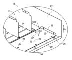
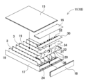
本開示の実施形態1に係る電源装置100を図1~図11に示す。これらの図において、図1は実施形態1に係る電源装置100に、一の電池モジュール2を挿抜する状態を示す分解斜視図、図2は図1の電源装置100を背面側から見た分解斜視図、図3は図1の電源装置100の電源ケース10の分解斜視図、図4は図3の電源ケース10を背面側から見た分解斜視図、図5は図4の電源ケース10から回路基板30と絶縁シート34を外した分解斜視図、図6は図5の電源ケース10の拡大斜視図、図7は図5の電源ケース10からプレート部20を外した分解斜視図、図8は図1の電源装置100のVIII-VIII線における垂直断面図、図9は図1の電池モジュール2の分解斜視図、図10は実施形態1に係る電源装置100の模式断面図、図11は図10のケース本体11に異なる長さの電池モジュール2’を挿入した状態を示す模式断面図を、それぞれ示している。これらの図に示す電源装置100は、電源ケース10と、電池モジュール2を備える。また電源ケース10の背面側には、回路基板30が配置される。
本開示の実施形態1に係る電源装置100を図1~図11に示す。これらの図において、図1は実施形態1に係る電源装置100に、一の電池モジュール2を挿抜する状態を示す分解斜視図、図2は図1の電源装置100を背面側から見た分解斜視図、図3は図1の電源装置100の電源ケース10の分解斜視図、図4は図3の電源ケース10を背面側から見た分解斜視図、図5は図4の電源ケース10から回路基板30と絶縁シート34を外した分解斜視図、図6は図5の電源ケース10の拡大斜視図、図7は図5の電源ケース10からプレート部20を外した分解斜視図、図8は図1の電源装置100のVIII-VIII線における垂直断面図、図9は図1の電池モジュール2の分解斜視図、図10は実施形態1に係る電源装置100の模式断面図、図11は図10のケース本体11に異なる長さの電池モジュール2’を挿入した状態を示す模式断面図を、それぞれ示している。これらの図に示す電源装置100は、電源ケース10と、電池モジュール2を備える。また電源ケース10の背面側には、回路基板30が配置される。
(電源ケース10)
電源ケース10は、一以上の電池モジュール2を、挿抜自在に収納するための部材であり、電源装置100の外形を構成する。電源ケース10は外形を箱状とするケース本体11で構成され、第一面12と、その対向面である第二面13を有する。図1、図2等の例では、ケース本体11の正面側を第一面12、背面側を第二面13としている。第一面12には、電池モジュール2をそれぞれ挿抜するための挿抜口14を開口している。図1、図2等の例では、電源ケース10のケース本体11の外形を平板状として、正面側の第一面12に挿抜口14を水平面状に並べており、複数の電池モジュール2を横並びに配置している。
電源ケース10は、一以上の電池モジュール2を、挿抜自在に収納するための部材であり、電源装置100の外形を構成する。電源ケース10は外形を箱状とするケース本体11で構成され、第一面12と、その対向面である第二面13を有する。図1、図2等の例では、ケース本体11の正面側を第一面12、背面側を第二面13としている。第一面12には、電池モジュール2をそれぞれ挿抜するための挿抜口14を開口している。図1、図2等の例では、電源ケース10のケース本体11の外形を平板状として、正面側の第一面12に挿抜口14を水平面状に並べており、複数の電池モジュール2を横並びに配置している。
具体的には、図3~図7の分解斜視図に示すように、ケース本体11を、第一本体ケース15と第二本体ケース16と第三本体ケース17と第四本体ケース18に4分割している。第一本体ケース15と第二本体ケース16は、蓋を構成し、上面を開口するようにコ字状に折曲した第三ケースの上面を第一本体ケース15と第二本体ケース16で閉塞する。また、ケース本体11の背面である第二面13を、第四本体ケース18で閉載する。さらにケース本体11の内部に、複数の仕切り板19を平行状に互いに離間させて固定して、複数の収納空間3を画成する。各収納空間3は、挿抜口14から連通して、電池モジュール2を収納する。なお図3~図7の例では、図示の関係上、複数の仕切り板19を第三本体ケース17の底面に固定した状態を示しているが、第三本体ケース17に代えて、あるいは第三本体ケース17に加えて、第一本体ケース15に複数の仕切り板19を固定してもよいことはいうまでもない。また第二本体ケース16は、複数の仕切り板19を第一本体ケース15や第三本体ケース17に固定した状態で、回路基板30やプレート部20にアクセスし易いように、第一本体ケース15と別に構成したものである。
(回路基板30)
さらにまたケース本体11の背面側で、第二面13と電池モジュール2との間には、回路基板30が配置される。回路基板30は、電池モジュール2の挿入方向に沿う姿勢に、ケース本体11内に載置されている。すなわち回路基板30は、電池モジュール2と第二面13の間で水平姿勢で保持される。
さらにまたケース本体11の背面側で、第二面13と電池モジュール2との間には、回路基板30が配置される。回路基板30は、電池モジュール2の挿入方向に沿う姿勢に、ケース本体11内に載置されている。すなわち回路基板30は、電池モジュール2と第二面13の間で水平姿勢で保持される。
回路基板30は、充放電の電流を検出する電流検出回路や、互いに接続された複数の二次電池セルをそれぞれ有する電池ブロックの電池側回路基板から入力される二次電池セルの電圧や温度等の電池情報から二次電池セルの満充電や残容量を検出、演算する回路や、二次電池セルの充放電を制御する制御回路、あるいは電池が正常であるかどうかを監視する保護回路等の電子回路を実装している。回路基板30は、矩形状に形成されている。図4等の例では、回路基板30は、電源ケース10の背面側において水平姿勢に固定される。この回路基板30は、例えばガラスエポキシ等の樹脂製とすることが好ましい。
また回路基板30をケース本体11内部に設置するにあたり、図5に示すように絶縁シート34を介在させてもよい。これにより、回路基板30の裏面側での絶縁性を高めることができる。
なお電源ケースは、上述した形態に限られず、筐体部を縦置きに並べるよう、挿抜口をケース本体の上下方向に積層してもよい。また、碁盤目状に筐体部を配置するよう構成してもよい。なお、電源ケース10の挿抜口14のすべてに筐体部を挿入する必要はなく、電源装置に要求される出力や容量等に応じて、電源ケースに挿入する筐体部の数を設定してもよい。また挿抜口の開口端の形状や長さは、挿抜される電池モジュールの大きさに応じて設計される。さらにケース本体11は、放熱性に優れた板金などの金属製とすることが好ましい。
(電池モジュール2)
電池モジュール2は、ケース本体11の挿抜口14に挿抜される。電池モジュール2の外形は、挿抜し易いよう一方向に延長された棒状に形成される。棒状の電池モジュール2は、箱形に形成することが好ましい。箱形の電池モジュール2は、長手方向DLの一方の端面を、ケース本体11に各筐体を挿入する挿入面41とする。また他方の端面を、ケース本体11に挿入された状態で、このケース本体11から表出する表出面42とする。図1等の例では、端面を正方形状とする角柱状に形成されている。ただ、電池モジュールの形状はこれに限らず、端面を長方形状や八角形状等としてもよい。
電池モジュール2は、ケース本体11の挿抜口14に挿抜される。電池モジュール2の外形は、挿抜し易いよう一方向に延長された棒状に形成される。棒状の電池モジュール2は、箱形に形成することが好ましい。箱形の電池モジュール2は、長手方向DLの一方の端面を、ケース本体11に各筐体を挿入する挿入面41とする。また他方の端面を、ケース本体11に挿入された状態で、このケース本体11から表出する表出面42とする。図1等の例では、端面を正方形状とする角柱状に形成されている。ただ、電池モジュールの形状はこれに限らず、端面を長方形状や八角形状等としてもよい。
各電池モジュール2は、図9に示すように箱形のモジュール筐体43に複数の二次電池セル1を収納している。各電池モジュール2は、内部の収納する複数本の二次電池セル1を直列や並列に接続した出力を、電源ケース10側に出力する。このため電池モジュール2は、電源ケース10と接続するための電池側コネクタ44を設けている。またケース本体11は、電池側コネクタ44と接続するケース側コネクタ32を設けている。
電池側コネクタ44は、電池モジュール2の挿入面41側に設けられる。またケース側コネクタ32は、回路基板30上で、電池モジュール2の挿入面41と対向する姿勢に設けられる。電池モジュール2をケース本体11に挿入し、挿入面41が後述するストッパ部21に当接して停止される位置において、電池側コネクタ44がケース側コネクタ32と係合されるように、これら電池側コネクタ44とケース側コネクタ32が配置されている。
電池モジュール2のモジュール筐体43は、図9の分解斜視図に示すように、前後方向に延長された箱形に形成されており、その内部に内部アセンブリ45のアセンブリ収納空間を設けている。このモジュール筐体43は、断面視コ字状で下面を開口した第一モジュールケース43Aと、第一モジュールケース43Aの下面を閉塞する第二モジュールケース43Bと、で構成される。これらの第一モジュールケース43A、第二モジュールケース43Bは、金属板を折曲加工するなどして所定の形状に形成している。このような金属板としては、例えば溶融亜鉛めっき鋼板、アルミニウムやアルミニウム合金が使用できる。
またモジュール筐体43の内部のアセンブリ収納空間には、内部アセンブリ45を収納している。内部アセンブリ45は、複数の二次電池セル1を含む電池ブロックと、出力端子を備える出力ユニットを備えている。電池ブロックは、例えば多数の円筒型の二次電池セル1を垂直姿勢で互いに平行な姿勢となるように並べて電池ホルダに収納している。電池ホルダは、好ましくは、絶縁性、耐熱性に優れた材質で構成され、例えばポリカーボネートやABS等の樹脂製とする。複数の二次電池セル1は、並列及び直列に接続される。この二次電池セル1は、リチウムイオン二次電池である。二次電池セル1をリチウムイオン二次電池とする電池モジュール2は、容積と重量に対する出力を大きくできる。ただ、二次電池セルには、リチウムイオン電池に代わって、リチウムポリマー電池やニッケル水素電池も使用できる。したがって、本開示は、二次電池セルをリチウムイオン電池に特定せず、二次電池セルには、充電できる全ての電池を使用できる。
さらに電池ブロックは、電池ホルダの側面に垂直姿勢でモジュール基板を配置しており、二次電池セル1の端面電極に接続されたリード板46をモジュール筐体43に接続して、互いに直列に接続される二次電池セル1の中間電位を検出している。さらに、モジュール筐体43は、複数の二次電池セル1の状態を検出する電子回路を備えている。この電子回路は、二次電池セル1が直列や並列に接続された電池集合体の総電位や、中間の電位を検出する電圧検出回路や、複数の二次電池セル1の温度を検出する回路を含んでいる。
(プレート部20)
また電源ケース10は、図5~図7、図10に示すように、ケース本体11の一部に固定される、ケース本体11と別部材で構成されたプレート部20を備えている。プレート部20は、複数の電池モジュール2を各端面(挿入面41)側からそれぞれ、ケース本体11の各挿抜口14から第二面13側に向かって挿入する際に、該電池モジュール2の端面(挿入面41)と干渉するすなわち当接することで押し込み量を規制するストッパ部21を設けている。このように、ストッパ部21を設けたプレート部20をケース本体11と別部材で構成することで、挿入する電池モジュール2’のモジュール長さが、図10のL1から図11のL2に変更されても、これに応じてストッパ部21’の位置を変更したプレート部20’を準備することで対応でき、ケース本体11を再設計する事態を回避できる。
また電源ケース10は、図5~図7、図10に示すように、ケース本体11の一部に固定される、ケース本体11と別部材で構成されたプレート部20を備えている。プレート部20は、複数の電池モジュール2を各端面(挿入面41)側からそれぞれ、ケース本体11の各挿抜口14から第二面13側に向かって挿入する際に、該電池モジュール2の端面(挿入面41)と干渉するすなわち当接することで押し込み量を規制するストッパ部21を設けている。このように、ストッパ部21を設けたプレート部20をケース本体11と別部材で構成することで、挿入する電池モジュール2’のモジュール長さが、図10のL1から図11のL2に変更されても、これに応じてストッパ部21’の位置を変更したプレート部20’を準備することで対応でき、ケース本体11を再設計する事態を回避できる。
ここで、比較例に係るデータセンター向けの電源装置600を図12の分解斜視図に示す。この図に示すようにデータセンター向けの電源装置600は、電源ケース610と、電源ケース610に挿抜される複数の電池モジュール602と、電装部品630で構成される。電池モジュール602は、着脱可能な構造となっており、交換可能に構成されている。このような電源装置600は、電池モジュール602の抜き差しの際、電池モジュール602と電装部品630とが干渉しないように、電源ケース610にストッパ部が設けられている。ストッパ部は、電池モジュール602の挿入しろの位置決めのために設けられており、輪留め等とも呼ばれる。図13の電源装置700においては、ストッパ部721としてピン状の形態のものが利用されている。
このようなストッパ部821を用いて、図14の模式断面図に示すように、電池モジュール802を電源ケース810に挿入する際、電池モジュール802の位置決めを行っている。具体的には、電池モジュール802を規定の位置まで押し込んだ状態で、それ以上電池モジュール802を押し込めないように、ストッパ部821が電池モジュール802の端面と当接する。これにより、電池モジュール802は定位置に保持される。またこの状態で、電源ケース810の奥側に配置された回路基板830上に実装されたケース側コネクタ832に、電池モジュール802の端面に設けられた電池側コネクタ844が嵌合されて、電池モジュール802は電源ケース810の回路基板830と電気的に接続される。
このようなデータセンター向けの電源装置は、ラック等の収納スペースに挿入されて使用される。一方で、データセンター向け等の用途で利用される設備類は、電源装置も含めたサーバー、ストレージ、ネットワークスイッチなどのハードウェアを規格に準拠した製品とすることが一般的となっている。例えばバックアップ用途に利用される電池モジュールは、ラックの中央に配置される電源装置の中に6つ搭載される。このような規格は複数あるところ、代表的な規格においては、ラックに搭載する機器の高さをOU(オープンユニット)と呼ばれる単位で規定されている。この内、1OUは1.89インチ(48mm)であり、その幅は21インチ(533.4mm)となっている。
近年、生成AIの需要増などにより、電源装置を構成する電池モジュール2の高容量、高出力化が要求されている。しかしながら、規格の制約により、電池モジュールの幅方向にサイズを大きくすることができない。このため、電池モジュールを大きくする必要がある。この場合、電源装置を設置するラックのサイズを変更せずに、電池モジュールを大型化するには、電源装置の奥行方向、すなわち電池モジュールを挿入する長手方向に電池モジュールを大きくする必要がある。したがって、電源装置を設置するラックの収納スペースの奥側の電装部を縮小する必要があった。
例えば図14に示す電源装置800において、電池モジュール802の容量を増やすために、図15に示す電源装置900のように全長を図14のモジュール長さL1よりも長い、L2とした電池モジュール902を、電源ケース910にセットする例を考える。電装部を構成する回路基板930の基板長さも、これに応じてB1からB2に縮小される。この場合、電池モジュール902の長さが図14の電池モジュール802よりも長いため、電池モジュール902を電源ケース910内に定位置に位置決めするためのストッパ部921の位置は、図14のストッパ部821よりも左側にずらす必要がある。この結果、図15の電源ケース910は図14の電源ケース810と外形は同じであるものの、その内部においてストッパ部を設けた位置が異なるため、新たに設計し直す必要があった。このように、電池モジュールの挿入しろ位置決めとなるストッパ部の位置は、電池モジュールの長手方向の長さによって変わるため、長手方向の長さが異なる電位モジュールに対して電源ケースの設計を共通化することはできなかった。
これに対し本実施形態に係る電源装置100では、図7の分解斜視図に示すように、ケース本体11と別部材で構成されたプレート部20にストッパ部21を設けることで、ケース本体11に挿入する電池モジュール2の長さがL1からL2に変更されても、これに応じてストッパ部21の位置を変更したプレート部20に交換すれば、ケース本体11を再設計することなく対応でき、多品種の電池モジュール2に対してもケース本体11を共通化して製造コストの削減を図ることが可能となる。
特にデータセンターのバックアップ用電源装置においては、電池モジュール等の口径のサイズが規格上で規定されているため、電池モジュールを大きくして高容量化を図るには奥行方向にしか延長できないところ、奥行方向にモジュール長さを変更するとストッパ部を含む電源ケース自体を設計し直さねばならない問題を、ストッパ部21を別部材のプレート部20に設けることで、ケース本体11を共通としたまま対応可能とできるようになる。
ストッパ部21を設ける位置は、電池モジュール2のモジュール長さに応じて決定される。図10のように、電池モジュール2のモジュール長さL1に応じて、ケース本体11の第一面12からL1の位置にストッパ部21が設けられる。一方、図11のように電池モジュール2’がモジュール長さL2の場合は、ストッパ部21’はプレート部20’において第一面12からL2の位置に設けられる。このように、電池モジュール2のモジュール長さに応じて、ストッパ部21を設ける位置を調整できるように、プレート部20の奥行方向、すなわち電池モジュール2を挿入する長手方向DLのプレート長さD1は、想定される電池モジュール2のモジュール長さに応じて設計される。具体的には、D1>(想定される電池モジュールのモジュール長さの最大値Lmax)-(想定される電池モジュールのモジュール長さの最小値Lmin)となるように、プレート長さを設計することが好ましい。
また、プレート部20は、回路基板30の一部を固定するためのプレート側基板固定部22を設けている。このような構成とすることで、図11に示すようにケース本体11に挿入される電池モジュール2’の長さの変更に応じて、回路基板30’の奥行方向の幅、すなわち基板長さを変更した際にも、プレート部20’に設けるプレート側基板固定部22’の位置を、変更した回路基板30’の基板長さに応じて調整でき、ケース本体11を再設計することなく、異なる基板長さの回路基板30に対応できる。
一方でケース本体11は、回路基板30の他の一部を固定するためのケース側基板固定部36を設けている。回路基板30は、ケース側基板固定部36とプレート側基板固定部22によって、ケース本体11及びプレート部20に固定される。図6、図7の例では、これらケース側基板固定部36やプレート側基板固定部22は、内面にねじ溝を切った円柱状のスペーサでそれぞれ構成されているが、ケース側基板固定部36やプレート側基板固定部22はこれに限定されず、回路基板30を固定可能な既知の構成を適宜利用できる。
また、ケース側基板固定部36の固定位置は、ケース本体11の第二面13側近傍に固定されている一方、プレート側基板固定部22は、回路基板30の基板長さに応じて決定される。すなわち、上述の通り基板長さは、モジュール長さによって変化することがあるため、回路基板30の基板長さの変更によって、ケース本体11を設計し直すことを避けるために、プレート部20のプレート側基板固定部22を調整することで対応している。具体的には、図10の例では、回路基板30の基板長さB1に応じて、第二面13から概ねB1の位置に、プレート側基板固定部22が設けられるように、プレート部20にプレート側基板固定部22を設ける位置を設計する。また図11の例では、モジュール長さL2に応じて短くなった回路基板30’の基板長さB2に応じて、第二面13から概ねB2の位置にプレート側基板固定部22’が配置されるように、プレート部20’にプレート側基板固定部22を設ける位置を設計する。このようにすることで、基板長さの変更にも、プレート部20の設計を変更することで対応でき、ケース本体11の共通化に資する。
プレート部20は、各収納空間3の底面3Bにおいて、プレート部20の端面120Eを底面3Bよりも上に表出させないように固定されている。いいかえると、長手方向DLに見て、収納空間3の底面3Bからプレート部20が上方向Duに突出しないようにしている。長手方向DLに見て、プレート部20の端面120Eを各収納空間3の底面3Bよりも上に表出させない。このような構成とすることで、電池モジュール2を電源ケース10に挿入する際にプレート部20の端面120Eが引っ掛かって挿入を妨げる事態を回避できる。
具体的には、プレート部20は各収納空間3の底面3Bと連なる位置に固定される。すなわち、ケース本体11の内面に画成された収納空間3に電池モジュール2を載置する載置面と、プレート部20の上面120Aとが、同一平面状となるように形成される。
図7等の例では、ケース本体11の底面の一部に底面開口24を開口させている。プレート部20は、底面開口24を閉塞するように配置されている。これにより、プレート部20をケース本体11に付加しつつも、プレート部20の追加による高さ方向の変化を生じさせずに、電池モジュール2を押し込む際にプレート部20が干渉する事態を回避できる。
[変形例]
このように、ケース本体11にプレート部20を付加しつつ、収納空間3の底面3Bとプレート部20の上面120Aを同一平面状にそろえるための構成は、底面開口24を開口させる形態に限られない。一例として、図16の模式断面図に示す変形例に係る電源装置100’では、ケース本体11の底面の一部で、プレート部20を固定する部位を部分的に凹状に窪ませた凹部24’を形成している。このような構成であっても、プレート部20の上面120Aを収納空間3の底面3Bとそろえ、またプレート部20の端面120Eが突出する事態を回避することが可能となる。またこの構成であれば、ケース本体11に開口を設ける構成に比べ、開口を設けないこと、及びケース本体11を部分的に二重にすることで、ケース本体11の剛性を高められるという利点も得られる。
このように、ケース本体11にプレート部20を付加しつつ、収納空間3の底面3Bとプレート部20の上面120Aを同一平面状にそろえるための構成は、底面開口24を開口させる形態に限られない。一例として、図16の模式断面図に示す変形例に係る電源装置100’では、ケース本体11の底面の一部で、プレート部20を固定する部位を部分的に凹状に窪ませた凹部24’を形成している。このような構成であっても、プレート部20の上面120Aを収納空間3の底面3Bとそろえ、またプレート部20の端面120Eが突出する事態を回避することが可能となる。またこの構成であれば、ケース本体11に開口を設ける構成に比べ、開口を設けないこと、及びケース本体11を部分的に二重にすることで、ケース本体11の剛性を高められるという利点も得られる。
ケース本体11は、図1、図3等に示すように、その第一面12において、複数の挿抜口14を横並びに開口させている。またプレート部20は、図5~図7等に示すように、複数の収納空間3を横切るように、収納空間3と交差する方向に延長されている。これにより、一枚のプレート部20でもって、複数の電池モジュール2の端面である挿入面41の押し込み量を規制できる。
またプレート部20の端縁には、図7、図17等に示すようにケース本体11の端縁と部分的に係止される係止片26を設けることができる。これにより、収納空間3の底面3Bとプレート部20の上面120Aとを同一平面状にそろえ易くできる。また、係止片26は、電池モジュール2の挿入の妨げとならないように、薄く形成したり、設ける位置を調整することが好ましい。
(ストッパ部21)
プレート部20、20’は、複数のストッパ部21、21’を設けている。各ストッパ部21、21’は、図10、図11等に示すように、電池モジュール2、2’をケース本体11の挿抜口14から第二面13側に向かって挿入する際に、電池モジュール2、2’の挿入面41と干渉することで押し込み量を規制する。このためストッパ部21、21’は、各収納空間3に対応する位置に、それぞれ設けられる。図10等の例では、収納空間3毎に一個のストッパ部21が設けられているが、この構成に限られず、例えば収納空間毎に複数個のストッパ部を設けてもよい。
プレート部20、20’は、複数のストッパ部21、21’を設けている。各ストッパ部21、21’は、図10、図11等に示すように、電池モジュール2、2’をケース本体11の挿抜口14から第二面13側に向かって挿入する際に、電池モジュール2、2’の挿入面41と干渉することで押し込み量を規制する。このためストッパ部21、21’は、各収納空間3に対応する位置に、それぞれ設けられる。図10等の例では、収納空間3毎に一個のストッパ部21が設けられているが、この構成に限られず、例えば収納空間毎に複数個のストッパ部を設けてもよい。
ストッパ部21は、電池モジュール2の挿入面41に干渉して、ストッパ部21の位置よりも奥側に電池モジュール2を押し込むことを妨げられれば足りるので、その形状は干渉し易い任意の形状とできる。図17の斜視図に示す例では、アーチ状にストッパ部21を形成している。ここでは、アート状のストッパ部21は断面視において半円状に形成されている。このようなストッパ部21は、プレート部20を金属板で形成する際、打ち抜きによって容易に形成できる利点が得られる。
[実施形態2]
また図18に示す実施形態2に係る電源装置では、プレート部20Bに設けたストッパ部21Bを、片面を開口させたフード状に形成している。このストッパ部21Bはフード状の開口面でもって、電池モジュール2の端面である挿入面41に干渉するすなわち当接する。このようなストッパ部21Bも同様に金属板の打ち抜き加工によって容易に形成できる。なお、図18のストッパ部21Bは、フード状の開口面が電池モジュール2の挿入面41側と対向する向きに形成する必要がある。ストッパ部21Bが逆向きでは、フード状の傾斜面に沿って電池モジュール2の押し込みを規制できない可能性があるためである。
また図18に示す実施形態2に係る電源装置では、プレート部20Bに設けたストッパ部21Bを、片面を開口させたフード状に形成している。このストッパ部21Bはフード状の開口面でもって、電池モジュール2の端面である挿入面41に干渉するすなわち当接する。このようなストッパ部21Bも同様に金属板の打ち抜き加工によって容易に形成できる。なお、図18のストッパ部21Bは、フード状の開口面が電池モジュール2の挿入面41側と対向する向きに形成する必要がある。ストッパ部21Bが逆向きでは、フード状の傾斜面に沿って電池モジュール2の押し込みを規制できない可能性があるためである。
[実施形態3]
さらに図19に示す実施形態3に係る電源装置では、プレート部20Cに設けたストッパ部21Cを、金属製のプレート部20にコ字状の切り込みを入れて引き起こすようにして形成している。この構成のストッパ部21も、容易に形成できる利点が得られる。図19のストッパ部21Cも、切り込みが電池モジュール2側となる姿勢に形成することが好ましい。逆向きでは、引き起こしたストッパ部21を、電池モジュール2の押し込みによって倒してしまう懸念があるからである。また、図19の状態から、各ストッパ部21Cをいずれかの方向に90°回転させて形成してもよい。これにより、ストッパ部21Cの端縁でもって電池モジュール2の挿入面41に干渉し、ストッパ部21Cが押し込みによって倒れる方向に曲がる懸念を回避できる。
さらに図19に示す実施形態3に係る電源装置では、プレート部20Cに設けたストッパ部21Cを、金属製のプレート部20にコ字状の切り込みを入れて引き起こすようにして形成している。この構成のストッパ部21も、容易に形成できる利点が得られる。図19のストッパ部21Cも、切り込みが電池モジュール2側となる姿勢に形成することが好ましい。逆向きでは、引き起こしたストッパ部21を、電池モジュール2の押し込みによって倒してしまう懸念があるからである。また、図19の状態から、各ストッパ部21Cをいずれかの方向に90°回転させて形成してもよい。これにより、ストッパ部21Cの端縁でもって電池モジュール2の挿入面41に干渉し、ストッパ部21Cが押し込みによって倒れる方向に曲がる懸念を回避できる。
なお以上の例では、プレート部20を金属板で形成する例を説明した。金属板は強度が高く、加工も容易であり好ましい。一方で、図7等に示すように、プレート部20の上面120Aに固定する回路基板30との絶縁を考慮する必要があり、絶縁シート34の付加等のケアが必要となる。
[電源装置の製造方法]
このような電源装置の製造方法を、以下説明する。ここでは電源装置100は、複数の電池モジュール2と、電源ケース10とを備える。複数の電池モジュール2は、それぞれ複数の二次電池セルを接続している。電源ケース10は、ケース本体11とプレート部20を備える。ケース本体11は、複数の電池モジュール2を、挿抜可能な状態にそれぞれ収納する複数の挿抜口14を開口した第一面12と、第一面12と対向する第二面13とを有する。プレート部20は、ケース本体11の一部に固定され、ケース本体11と別部材で構成される。
このような電源装置の製造方法を、以下説明する。ここでは電源装置100は、複数の電池モジュール2と、電源ケース10とを備える。複数の電池モジュール2は、それぞれ複数の二次電池セルを接続している。電源ケース10は、ケース本体11とプレート部20を備える。ケース本体11は、複数の電池モジュール2を、挿抜可能な状態にそれぞれ収納する複数の挿抜口14を開口した第一面12と、第一面12と対向する第二面13とを有する。プレート部20は、ケース本体11の一部に固定され、ケース本体11と別部材で構成される。
まず、複数の電池モジュール2を各端面である挿入面41側からそれぞれ、ケース本体11の各挿抜口14から第二面13側に向かって挿入する際に、該電池モジュール2の挿入面41と干渉することで押し込み量を規制するストッパ部21を設けたプレート部20を準備する。次に、プレート部20を、ケース本体11の一部に固定する。これにより、ストッパ部21を設けたプレート部20をケース本体11と別部材で構成することにより、挿入する電池モジュール2の長さが変更されても、これに応じてストッパ部21の位置を変更したプレート部20のみを交換することで対応でき、ケース本体11を再設計する事態を回避できる。
プレート部20を準備する工程は、想定される電池モジュール2のモジュール長さの最大値をLmax、想定される電池モジュールのモジュール長さの最小値をLminとするとき、プレート部20の奥行方向のプレート長さD1を、D1>Lmax-Lminとなるように決定する工程を含むことができる。これにより、プレート部20のプレート長さの範囲内で、ストッパ部21を設ける位置を変更して、想定される電池モジュール2のモジュール長さの全域に対応可能とできる。
本開示に係る電源装置及び電源装置用電源ケース並びに電源装置の製造方法は、据え置き型の蓄電装置、例えば家庭用、事業所用、工場用の電源装置、あるいはデータセンターのバックアップ用電源等の用途として好適に利用できる。
100,100’ 電源装置
1 二次電池セル
2 電池モジュール
3 収納空間
10 電源ケース
11 ケース本体
12 第一面
13 第二面
14 挿抜口
15 第一本体ケース
16 第二本体ケース
17 第三本体ケース
18 第四本体ケース
19 仕切り板
20,20’20B,20C プレート部
21,21’,21B,21C ストッパ部
22,22’ プレート側基板固定部
24 底面開口
24’ 凹部
26 係止片
30,30’ 回路基板
32 ケース側コネクタ
34 絶縁シート
36 ケース側基板固定部
41 挿入面
42 表出面
43 モジュール筐体;
43A 第一モジュールケース
43B 第二モジュールケース;
44 電池側コネクタ
45 内部アセンブリ
46 リード板
600 電源装置
602 電池モジュール
610 電源ケース
630 電装部品
721 ストッパ部
800 電源装置
802 電池モジュール
810 電源ケース
821 ストッパ部
832 ケース側コネクタ
844 電池側コネクタ
900 電源装置
902 電池モジュール
910 電源ケース
921 ストッパ部
930 回路基板
L1,L2 モジュール長さ
B1,B2 基板長さ
D1 プレート長さ
1 二次電池セル
2 電池モジュール
3 収納空間
10 電源ケース
11 ケース本体
12 第一面
13 第二面
14 挿抜口
15 第一本体ケース
16 第二本体ケース
17 第三本体ケース
18 第四本体ケース
19 仕切り板
20,20’20B,20C プレート部
21,21’,21B,21C ストッパ部
22,22’ プレート側基板固定部
24 底面開口
24’ 凹部
26 係止片
30,30’ 回路基板
32 ケース側コネクタ
34 絶縁シート
36 ケース側基板固定部
41 挿入面
42 表出面
43 モジュール筐体;
43A 第一モジュールケース
43B 第二モジュールケース;
44 電池側コネクタ
45 内部アセンブリ
46 リード板
600 電源装置
602 電池モジュール
610 電源ケース
630 電装部品
721 ストッパ部
800 電源装置
802 電池モジュール
810 電源ケース
821 ストッパ部
832 ケース側コネクタ
844 電池側コネクタ
900 電源装置
902 電池モジュール
910 電源ケース
921 ストッパ部
930 回路基板
L1,L2 モジュール長さ
B1,B2 基板長さ
D1 プレート長さ
Claims (13)
- 複数の二次電池セルをそれぞれ有する複数の電池モジュールと、
前記複数の電池モジュールを収納する電源ケースと、
を備える電源装置であって、
電源ケースは、
前記複数の電池モジュールを挿抜可能な状態にそれぞれ収納する複数の挿抜口を開口した第一面と、前記第一面と対向する第二面と、を有するケース本体と、
前記ケース本体の一部に固定される、前記ケース本体と別部材で構成されたプレート部と、
を備え、
前記プレート部は、前記複数の電池モジュールを前記複数の電池モジュールの各端面側からそれぞれ、前記ケース本体の前記複数の挿抜口の各挿抜口から前記第二面側に向かって挿入する際に、前記複数の電池モジュールの前記各端面と干渉することで押し込み量を規制するストッパ部を設けてなる電源装置。 - 請求項1に記載の電源装置であって、
前記ケース本体は、前記複数の挿抜口からそれぞれ連通して、前記複数の電池モジュールをそれぞれ収納する複数の収納空間を内部に形成しており、
前記複数の収納空間の各収納空間の底面において、前記プレート部の端面を該底面よりも上に表出させない電源装置。 - 請求項1に記載の電源装置であって、
前記ケース本体の内面において、前記ケース本体の、前記複数の電池モジュールを載置する載置面と、前記プレート部の上面とが、同一平面状に形成されてなる電源装置。 - 請求項1に記載の電源装置であって、
前記ケース本体は、その底面の一部を開口させた底面開口を形成しており、
前記プレート部が、前記底面開口を閉塞するように配置されてなる電源装置。 - 請求項1に記載の電源装置であって、さらに、
前記ケース本体の内部において、前記複数の電池モジュールの端面と、前記第二面との間に配置される回路基板を備えており、
前記プレート部は、前記回路基板の一部を固定するためのプレート側基板固定部を設けてなる電源装置。 - 請求項5に記載の電源装置であって、
前記ケース本体は、前記回路基板の他の一部を固定するためのケース側基板固定部を設けてなる電源装置。 - 請求項5に記載の電源装置であって、
前記回路基板は、前記電池モジュールの挿入方向に沿う姿勢に、前記ケース本体内に載置されてなる電源装置。 - 請求項1~7のいずれか一項に記載の電源装置であって、
前記ケース本体は、前記第一面において、前記複数の挿抜口を、横並びに開口させてなる電源装置。 - 請求項1~7のいずれか一項に記載の電源装置であって、
前記ストッパ部が、断面視において半円状に形成されてなる電源装置。 - 請求項1~7のいずれか一項に記載の電源装置であって、
前記電源装置が、データセンター用のバックアップ電源である電源装置。 - 複数の二次電池セルをそれぞれ有する複数の電池モジュールを収納するための電源装置用電源ケースであって、
前記複数の電池モジュールを、挿抜可能な状態にそれぞれ収納する複数の挿抜口を開口した第一面と、前記第一面と対向する第二面と、を有するケース本体と、
前記ケース本体の一部に固定される、前記ケース本体と別部材で構成されたプレート部と、
を備え、
前記プレート部は、前記複数の電池モジュールを前記複数の電池モジュールの各端面側からそれぞれ、前記ケース本体の各挿抜口から前記第二面側に向かって挿入する際に、前記複数の電池モジュールの前記各端面と干渉することで押し込み量を規制するストッパ部を設けてなる電源装置用電源ケース。 - 複数の二次電池セルをそれぞれ有する複数の電池モジュールと、
前記複数の電池モジュールを収納する電源ケースと、
を備える電源装置であり、
前記電源ケースが、
前記複数の電池モジュールを、挿抜可能な状態にそれぞれ収納する複数の挿抜口を開口した第一面と、前記第一面と対向する第二面と、を有するケース本体と、
前記ケース本体の一部に固定される、前記ケース本体と別部材で構成されたプレート部とを備える電源ケースと、
を備える、電源装置の製造方法であって、
前記複数の電池モジュールを前記複数の電池モジュールの各端面側からそれぞれ、前記ケース本体の前記複数の挿抜口の各挿抜口から前記第二面側に向かって挿入する際に、前記複数の電池モジュールの前記各端面と干渉することで押し込み量を規制するストッパ部を設けた前記プレート部を準備する工程と、
前記プレート部を、前記ケース本体の一部に固定する工程と、
を含む電源装置の製造方法。 - 請求項12に記載の電源装置の製造方法であって、
前記プレート部を準備する工程が、前記複数の電池モジュールのモジュール長さの想定される最大値をLmaxとし、前記複数の電池モジュールの前記モジュール長さの想定される最小値をLminとするとき、前記プレート部の奥行方向のプレート長さD1を、
D1>Lmax-Lmin
となるように決定する工程を含む電源装置の製造方法。
Applications Claiming Priority (2)
| Application Number | Priority Date | Filing Date | Title |
|---|---|---|---|
| JP2023-217214 | 2023-12-22 | ||
| JP2023217214 | 2023-12-22 |
Publications (1)
| Publication Number | Publication Date |
|---|---|
| WO2025134685A1 true WO2025134685A1 (ja) | 2025-06-26 |
Family
ID=96138211
Family Applications (1)
| Application Number | Title | Priority Date | Filing Date |
|---|---|---|---|
| PCT/JP2024/041497 Pending WO2025134685A1 (ja) | 2023-12-22 | 2024-11-22 | 電源装置及び電源装置用電源ケース並びに電源装置の製造方法 |
Country Status (1)
| Country | Link |
|---|---|
| WO (1) | WO2025134685A1 (ja) |
Citations (3)
| Publication number | Priority date | Publication date | Assignee | Title |
|---|---|---|---|---|
| JPH0955196A (ja) * | 1995-08-11 | 1997-02-25 | Sanyo Electric Co Ltd | パック電池 |
| JP2011249018A (ja) * | 2010-05-22 | 2011-12-08 | Sanyo Electric Co Ltd | 電池パック用充電器 |
| JP2019117753A (ja) * | 2017-12-27 | 2019-07-18 | 日立化成株式会社 | 蓄電池システム及び電力システム |
-
2024
- 2024-11-22 WO PCT/JP2024/041497 patent/WO2025134685A1/ja active Pending
Patent Citations (3)
| Publication number | Priority date | Publication date | Assignee | Title |
|---|---|---|---|---|
| JPH0955196A (ja) * | 1995-08-11 | 1997-02-25 | Sanyo Electric Co Ltd | パック電池 |
| JP2011249018A (ja) * | 2010-05-22 | 2011-12-08 | Sanyo Electric Co Ltd | 電池パック用充電器 |
| JP2019117753A (ja) * | 2017-12-27 | 2019-07-18 | 日立化成株式会社 | 蓄電池システム及び電力システム |
Similar Documents
| Publication | Publication Date | Title |
|---|---|---|
| US11063316B2 (en) | Battery module including cross beam and battery pack comprising the same | |
| US8114536B2 (en) | Frame member and battery pack employed with the same | |
| US12166240B2 (en) | Battery module and battery pack including the same | |
| US9859533B2 (en) | Energy storage apparatus | |
| JP6257951B2 (ja) | 電池モジュール | |
| CN101346832B (zh) | 框架构件及使用该框架构件的电池组 | |
| US20140030581A1 (en) | Bus bar holder and battery pack including the same | |
| US10615394B2 (en) | Energy storage apparatus | |
| CN112005400B (zh) | 电池组 | |
| JPWO2018003467A1 (ja) | 電池ブロック及び電池モジュール | |
| CN107851751B (zh) | 蓄电装置 | |
| CN115917854B (zh) | 板式ess电池组 | |
| WO2025134685A1 (ja) | 電源装置及び電源装置用電源ケース並びに電源装置の製造方法 | |
| JP2002110115A (ja) | パック電池 | |
| EP4131603B1 (en) | Battery pack and manufacturing method therefor | |
| US20230369696A1 (en) | Battery pack and manufacturing method therefor | |
| KR100853620B1 (ko) | 전지모듈 제조용 스페이서 | |
| CN223285124U (zh) | 电池包及用电装置 | |
| WO2024180980A1 (ja) | 電池モジュール及び複数の電池モジュールを備える電源装置 | |
| TW202527361A (zh) | 電池組 | |
| JP2023001760A (ja) | 蓄電装置 |
Legal Events
| Date | Code | Title | Description |
|---|---|---|---|
| 121 | Ep: the epo has been informed by wipo that ep was designated in this application |
Ref document number: 24907073 Country of ref document: EP Kind code of ref document: A1 |
|
| ENP | Entry into the national phase |
Ref document number: 2025565168 Country of ref document: JP Kind code of ref document: A |
|
| WWE | Wipo information: entry into national phase |
Ref document number: 2025565168 Country of ref document: JP |