WO2025134253A1 - ファン装置、ウェアラブルデバイスおよびファンを駆動するプログラム - Google Patents
ファン装置、ウェアラブルデバイスおよびファンを駆動するプログラム Download PDFInfo
- Publication number
- WO2025134253A1 WO2025134253A1 PCT/JP2023/045625 JP2023045625W WO2025134253A1 WO 2025134253 A1 WO2025134253 A1 WO 2025134253A1 JP 2023045625 W JP2023045625 W JP 2023045625W WO 2025134253 A1 WO2025134253 A1 WO 2025134253A1
- Authority
- WO
- WIPO (PCT)
- Prior art keywords
- fan
- user
- wind
- unit
- face
- Prior art date
- Legal status (The legal status is an assumption and is not a legal conclusion. Google has not performed a legal analysis and makes no representation as to the accuracy of the status listed.)
- Pending
Links
Images













Classifications
-
- G—PHYSICS
- G06—COMPUTING OR CALCULATING; COUNTING
- G06F—ELECTRIC DIGITAL DATA PROCESSING
- G06F3/00—Input arrangements for transferring data to be processed into a form capable of being handled by the computer; Output arrangements for transferring data from processing unit to output unit, e.g. interface arrangements
- G06F3/01—Input arrangements or combined input and output arrangements for interaction between user and computer
Definitions
- This disclosure relates to technology that supplies wind to a user wearing a wearable device on their head.
- Patent Document 1 discloses a simulation game system in which a blower is placed on a movable housing in which a user sits, maintaining the relative positional relationship between the blower and the user, and controlling the blower to blow gas toward a blowing target in real space.
- a head mounted display is worn on the user's head and provides the user with a virtual reality (VR) visual world.
- VR virtual reality
- the user can operate a game controller to perform various inputs into the visual space provided by the game.
- the HMD provides VR images to the user's entire field of vision, it enhances the user's sense of immersion in the visual world.
- the present inventor has focused on the potential of wearable devices such as HMDs and smart glasses, and has investigated the realization of technology that will further enhance the user's sense of virtual reality and augmented reality.
- the present disclosure aims to provide a technology that provides wind to a user wearing a wearable device such as an HMD, thereby enhancing the user's sense of virtual reality or augmented reality, for example.
- One aspect of the present disclosure is a fan unit that is attached to a wearable device that is worn on the user's head, and includes a first fan unit having a fan that supplies air to the front of the user's face, a second fan unit having a fan that supplies air to the left side of the user's face, and a third fan unit having a fan that supplies air to the right side of the user's face.
- Another aspect of the present invention is a wearable device that is worn on the user's head, and includes a first fan unit having a fan that supplies air to the front of the user's face, a second fan unit having a fan that supplies air to the left side of the user's face, and a third fan unit having a fan that supplies air to the right side of the user's face.
- Another aspect of the present disclosure is a program executed on a computer of an information processing device, which causes the computer to perform the following functions: control the movement of a player character based on user operation input; identify the wind direction at the position of the player character in a virtual space; generate control signals for driving each of at least three fans attached to a wearable device based on the identified wind direction; and transmit the control signals.
- FIG. 1 is a diagram illustrating an example of a configuration of an information processing system according to an embodiment.
- 1A and 1B are diagrams illustrating examples of the external shape of an HMD.
- FIG. 2 is a diagram showing functional blocks of an HMD.
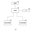
- FIG. 2 is a diagram illustrating functional blocks of the information processing device.
- FIG. 1 is a diagram showing an example of a cave route in a game.
- FIG. 4 is a diagram showing an example of a game image displayed on a display panel.
- FIG. 2 is a diagram illustrating an example of a fan device attached to an HMD.
- FIG. 13 is a diagram showing another example of a fan device attached to an HMD.
- FIG. 13 is a diagram showing another example of a fan device attached to an HMD.
- FIG. 13 is a diagram showing another example of a fan device attached to an HMD.
- FIG. 1 is a diagram illustrating an example of a configuration of an information processing system according to an embodiment.
- FIG. 13 is a diagram showing another example of a fan device attached to an HMD.
- FIG. 13 is a diagram showing another example of a fan device attached to an HMD.
- FIG. 2 is a diagram showing a state in which the fan device is attached to the HMD via a fixture.
- FIG. 2 is a diagram showing functional blocks of a fan unit.
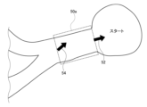
- FIG. 13 is a diagram illustrating an example of a plurality of subspaces.
- FIG. 13 is a diagram showing an example of wind parameters set in a subspace.
- FIG. 13 is a diagram showing the wind direction identified at the position of the player character.
- FIG. 1 is a diagram showing a three-dimensional representation of a subspace.
- FIG. 13 is a diagram showing an example of wind parameters set in a subspace.
- FIG. 13 is a diagram showing the wind direction identified at the position of the player character.
- 11 is a diagram showing the relative angle between the line of sight of the player character and the direction of the wind.
- FIG. 1 shows an example of the configuration of an information processing system 1 in an embodiment.
- the information processing system 1 is a game system including an information processing device 10 that executes a game, a head mounted display (HMD) 100 that is worn on the user's head, an input device 6 that the user holds and operates with his/her fingers, a recording device 11, and an output device 4 that outputs images and sounds.
- the output device 4 may be a television.
- the HMD 100 is an example of a wearable device that the user wears on his/her head, and the information processing system 1 may include wearable devices such as VR goggles, AR glasses, and smart glasses.
- the information processing device 10 is connected to an external network 2 such as the Internet via an access point (AP) 8.
- AP access point
- the recording device 11 records applications such as game software.
- the information processing device 10 may download game software from a content server (not shown) to the recording device 11 via the network 2.
- the information processing device 10 executes the game software (hereinafter simply referred to as "game") based on the user's operational input, generates image data and sound data of the game, and supplies them to the HMD 100.
- the information processing device 10 and the HMD 100 may be connected via a known wireless communication protocol, or may be connected by a cable.
- HMD100 is a display device that is worn on the user's head and displays images on a display panel located in front of the user's eyes. HMD100 separately displays an image for the left eye on the left eye display panel and an image for the right eye on the right eye display panel. These images form parallax images seen from the left and right viewpoints, achieving stereoscopic vision. Because the user views the display panel through optical lenses, the information processing device 10 supplies HMD100 with parallax image data that has been corrected for optical distortion caused by the lenses.
- the output device 4 is not necessary for the user wearing the HMD 100, but by providing the output device 4, another user can view the image displayed on the output device 4.
- the information processing device 10 may display on the output device 4 the same image as the image viewed by the user wearing the HMD 100, or may display a different image. For example, when a user wearing the HMD 100 and another user play a game together, the output device 4 may display a game image from the viewpoint of the character of the other user.
- the information processing device 10 and the input device 6 may be connected via a known wireless communication protocol, or may be connected by a cable.
- the input device 6 has multiple operating members such as operation buttons and an analog stick, and the user operates the operating members with his or her fingers while holding the input device 6.
- the input device 6 is used as a game controller.
- the game of the embodiment reflects information (operation input) obtained by the user operating the operating members of the input device 6 in the movement of the player character in a virtual three-dimensional space.
- the game may use the operation input of the left analog stick to move the player character, and the operation input of the right analog stick to change the line of sight of the player character.
- an inertial measurement unit IMU
- the game may treat the sensor data of the IMU as operation input for the input device 6 and reflect it in the movement of the player character (movement, change of line of sight, etc.).
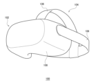
- FIG. 2 shows an example of the external shape of the HMD 100.
- the HMD 100 is composed of an output unit 102 and a fixed unit 104.
- the fixed unit 104 includes an attachment part 106 that the user wears to attach the HMD 100 to the user's head.
- the attachment part 106 has a material or structure that allows the length to be adjusted to fit the user's head circumference.
- the output unit 102 includes a housing 108 shaped to cover the left and right eyes when the user wears the HMD 100, and has a display panel inside that faces the eyes when worn.
- the display panel may be a liquid crystal panel or an organic EL panel.
- the housing 108 also has a pair of left and right optical lenses located between the display panel and the user's eyes to expand the user's field of view.
- the HMD 100 may further include speakers or earphones at positions corresponding to the user's ears, and may be configured to allow external headphones to be connected.
- FIG. 3 shows the functional blocks of the HMD 100.
- the control unit 120 is a main processor that processes and outputs various data such as image data, sound data, and sensor data, as well as commands.
- the memory unit 122 temporarily stores the data and commands processed by the control unit 120.
- the IMU 124 acquires sensor data related to the movement of the HMD 100.
- the IMU 124 may include at least a three-axis acceleration sensor and a three-axis angular velocity sensor.
- the IMU 124 detects the values of each axial component (sensor data) at a predetermined cycle (e.g., 800 Hz).
- the communication control unit 128 transmits data output from the control unit 120 to the external information processing device 10 by wired or wireless communication via a network adapter or an antenna.
- the communication control unit 128 also receives data from the information processing device 10 and outputs it to the control unit 120.
- control unit 120 When the control unit 120 receives game image data from the information processing device 10, it supplies it to the display panel 130 for display, and when it receives game sound data from the information processing device 10, it supplies it to the audio output unit 132 for audio output.
- the display panel 130 is composed of a left-eye display panel 130a and a right-eye display panel 130b, and a pair of parallax images are displayed on each display panel.
- the control unit 120 causes the communication control unit 128 to transmit the sensor data from the IMU 124 and the audio data from the microphone 126 to the information processing device 10.
- FIG. 4 shows functional blocks of the information processing device 10.
- the information processing device 10 includes a processing unit 200 and a communication unit 202, and the processing unit 200 includes an acquisition unit 210, a game execution unit 220, and a supply unit 240.
- the game execution unit 220 includes a player character control unit 222, a game image generation unit 224, a game sound generation unit 226, a posture identification unit 228, a wind direction identification unit 230, a wind speed identification unit 232, and a control signal generation unit 234.
- the communication unit 202 receives operation information of the operating members transmitted from the input device 6, and supplies it to the acquisition unit 210.
- the communication unit 202 also receives sensor data transmitted from the HMD 100, and supplies it to the acquisition unit 210.
- the functions of the components in the information processing device 10 may be implemented in circuitry or processing circuitry, including general purpose processors, application specific processors, integrated circuits, ASICs (Application Specific Integrated Circuits), a CPU (a Central Processing Unit), conventional circuits, and/or combinations thereof, configured or programmed to implement the functions described herein.
- a processor is considered to be a circuitry or processing circuitry that includes transistors and other circuits.
- a processor may be a programmed processor that executes a program stored in a memory.
- a circuit, unit, or means is hardware that is programmed to realize or executes the described functions.
- the hardware may be any hardware disclosed in this specification or any hardware that is programmed to realize or known to execute the described functions.
- the hardware is a processor that is considered to be a type of circuitry
- the circuitry, means, or unit may be a combination of hardware and software used to configure the hardware and/or processor.
- the acquisition unit 210 acquires operation information transmitted from the input device 6 and sensor data transmitted from the HMD 100, it supplies them to the game execution unit 220 as user operation input for the game.
- the game execution unit 220 executes a game in which the player character escapes from a complex cave like a maze.
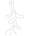
- Figure 5 shows an example of a cave route in the game. There are multiple route branching points between the start point and the goal point, and the player character can reach the goal point by following the correct route at all of the branching points.
- FIG. 6 shows an example of a game image displayed on the display panel 130.
- the game execution unit 220 of the embodiment executes a game program based on operational input from the user, and performs calculation processing to move the player character operated by the user within a cave, which is a three-dimensional virtual reality space.
- the player character control unit 222 controls the movement of the player character within the cave, specifically moving the player character based on operational input from the left analog stick, and determining the line of sight of the player character based on operational input from the right analog stick.
- the game image generating unit 224 includes a GPU (Graphics Processing Unit) that executes rendering processing, etc., and receives the results of calculation processing in the virtual reality space, and generates a game image captured from a virtual camera position in the virtual reality space.
- the game image generating unit 224 generates a game image from a first-person perspective, and generates a field of view image of the player character based on the line of sight determined by the player character control unit 222.
- the game image generating unit 224 generates a pair of parallax images consisting of a left-eye VR image and a right-eye VR image.
- the game sound generating unit 226 generates game sounds.
- the posture identification unit 228 identifies the posture of the HMD 100 using the sensor data transmitted from the HMD 100, and determines the user's line of sight.
- the game image generation unit 224 of the embodiment may use the user's line of sight identified by the posture identification unit 228 as the line of sight of the player character. Note that the game image generation unit 224 may match the user's line of sight with the line of sight of the player character (virtual camera), but may also correct the user's line of sight to determine the line of sight of the player character.
- the cave escape game is a time attack game, where the fastest time to reach the goal is competed for. If the player character takes the wrong route at a branching point, that route will become a dead end, resulting in a loss of time.
- the user is provided with hints about the direction to go, and uses those hints to select a route at each branching point.
- a fan device is attached to the HMD 100 worn on the user's head, and the fan device supplies wind to the user, providing a hint as to the direction of the cave opening (the goal point).
- the fan device of the embodiment is configured with at least three fans, and can supply wind to the user from any direction.
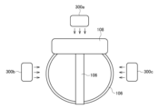
- FIG. 7 shows an example of a fan device attached to the HMD 100.
- FIG. 7 is a schematic diagram of a user wearing the HMD 100 viewed from the top of the head.
- the fan device shown in FIG. 7 has three fans, specifically fan 300a that supplies wind to the front of the user's face, fan 300b that supplies wind to the left side of the user's face, and fan 300c that supplies wind to the right side of the user's face.
- the front of the face may be referred to as the front of the head
- the left side of the face may be referred to as the left side of the head
- the right side of the face may be referred to as the right side of the head.
- FIG. 1 is a schematic diagram of a user wearing the HMD 100 viewed from the top of the head.
- the fan device shown in FIG. 7 has three fans, specifically fan 300a that supplies wind to the front of the user's face, fan 300b that supplies wind to the left side of the user's face, and fan 300c that supplies wind
- fans 300a, 300b, and 300c each indicate the direction of airflow, and fan 300a supplies wind directly in front of the user's face.
- the fan device shown in FIG. 7 includes fans 300a, 300b, and 300c, and by adjusting the rotation speed of each of the fans 300a, 300b, and 300c, it is possible to blow air in various directions onto the entire surface of the user's face (excluding the area covered by the HMD 100).
- fans 300 when there is no particular distinction between the fans included in the fan device, they may be simply referred to as "fans 300.”
- all of the multiple fans 300 are positioned below the components of the HMD 100. That is, fan 300a is positioned below the housing 108, and fans 300b and 300c are positioned below the attachment part 106 that secures the head. By positioning the fan 300 below the components of the HMD 100, the fan 300 can efficiently supply air to the user without being obstructed by the components.
- the orientation of the fan 300 is set so that the airflow direction faces the user's face (or head).
- the fan 300 may be positioned so that the airflow direction (air outlet direction) faces the central axis of the head.
- the fan 300 may be an axial flow blower that has a propeller fan and exhausts wind (air) in the axial direction during forward rotation.
- the fan 300 may also be of a type that exhausts wind (air) in the axial direction during forward rotation and sucks in wind (air) in the axial direction during reverse rotation.
- Various types of fan 300 can be used, but since it is attached to the HMD 100, it is preferable that it is small and lightweight.
- the attitude change mechanism 354 and/or the position change mechanism 356 do not need to be provided in all of the multiple fan units 320 constituting the fan device 310, but may be provided in at least one of the fan units 320.
- the fan unit 320 having the fan 300a may have the attitude change mechanism 354, and the fan unit 320 having the fans 300b and 300c may have the position change mechanism 356.
- the fan unit 320 having the fans 300b and 300c may further have the attitude change mechanism 354.
- the attitude change mechanism 354 and/or the position change mechanism 356 may be incorporated into the fan unit 320 as appropriate in order to increase the variety of winds supplied to the user.
- the player character control unit 222 controls the movement of the player character in the three-dimensional virtual space based on the user's operational input.
- the wind direction identification unit 230 identifies the wind direction at the position of the player character in the virtual space. Specifically, the wind direction identification unit 230 has a function of identifying the wind direction at the position of the player character based on information indicating the wind directions set at at least two positions in the virtual space.
- the cave which is a virtual space, is divided into multiple subspaces. It is not necessary for all areas of the cave to be divided into subspaces, but at least the areas of the cave that make up the route from the start to the goal must be divided into subspaces.
- the subspaces are areas that are set for the purpose of supplying wind to the user. While the player character is moving through the subspace, the user is supplied with wind from the fan device 310 indicating the direction to go, allowing the user to guess the correct direction of movement for the player character.
- FIG. 14 shows an example of multiple subspaces.
- the route from the start to the goal is divided into multiple subspaces 50a-50i (hereinafter referred to as "subspaces 50" unless otherwise specified).
- subspaces 50 are not set on routes that are dead ends, but in a modified example, subspaces may also be set on routes that are dead ends.
- the subspace 50 may have a rectangular parallelepiped shape and may be set to contain a three-dimensional cave. Adjacent subspaces 50 may have overlapping areas, and the multiple subspaces 50 cover the area of the cave from the start to the goal.
- a wind parameter is set in the subspace 50 to determine the wind direction within the subspace 50.
- the wind parameter includes information indicating the wind direction at at least two positions in the subspace 50.
- the wind direction determination unit 230 determines the wind direction at the position of the player character by interpolating and deriving the wind direction between the at least two positions based on the information indicating the wind direction set at the at least two positions in the subspace 50.
- the wind parameter in the subspace 50 may be set at the entrance and exit of the subspace 50.
- Figure 15 shows an example of wind parameters set in subspace 50a.
- a wind parameter 52 indicating the wind direction at the entrance is set at the entrance of subspace 50a
- a wind parameter 54 indicating the wind direction at the exit is set at the exit of subspace 50a. Note that in Figure 15, wind parameters 52, 54 are drawn to indicate two-dimensional wind direction by the direction of the arrow, but since the actual subspace 50a has a three-dimensional rectangular parallelepiped shape, wind parameters 52, 54 may indicate three-dimensional wind direction.
- the wind direction identification unit 230 identifies the wind direction at the position of the player character in the partial space 50a based on the wind parameters 52, 54 for the partial space 50a. Specifically, the wind direction identification unit 230 has a function of deriving, by interpolation, the wind direction at an arbitrary position between the entrance and exit of the partial space 50a based on the wind direction indicated by the wind parameters 52, 54. When the wind direction identification unit 230 acquires the position of the player character in the partial space 50a from the player character control unit 222, it may identify the wind direction at that position by interpolating the wind direction at the entrance and the wind direction at the exit of the partial space 50a. FIG. 16 shows the wind direction identified at the position of the player character.
- the wind direction identification unit 230 identifies the wind direction at the position of the player character from the wind parameter 52 at the entrance of the partial space 50a and the wind parameter 54 at the exit.
- the wind parameter 52 and the wind parameter 54 are set on opposite faces of a rectangular parallelepiped.
- the wind parameter 52 is a vector W E
- the wind parameter 54 is a vector W S
- the distance from the entrance to the exit of the partial space 50a is L
- the distance from the position of the player character to the exit is 1
- the wind direction at the position of the player character may be expressed as in the following formula (1).
- t l/L.
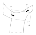
- Figure 18 shows an example of wind parameters set in subspace 50d.
- a wind parameter 56 indicating the wind direction at the entrance is set at the entrance of subspace 50d
- a wind parameter 58 indicating the wind direction at the exit is set at the exit of subspace 50d. Note that in Figure 18, wind parameters 56, 58 are drawn to indicate two-dimensional wind direction by the direction of the arrow, but since the actual subspace 50d has a three-dimensional shape, wind parameters 56, 58 may indicate three-dimensional wind direction.
- the wind direction identification unit 230 identifies the wind direction at the position of the player character in the partial space 50d based on the wind parameters 56, 58 for the partial space 50d. Specifically, the wind direction identification unit 230 has a function of deriving, by interpolation, the wind direction at an arbitrary position between the entrance and exit of the partial space 50d based on the wind direction indicated by the wind parameters 56, 58. When the wind direction identification unit 230 acquires the position of the player character in the partial space 50d from the player character control unit 222, it may identify the wind direction at that position by interpolating the wind direction at the entrance and the wind direction at the exit of the partial space 50d. FIG. 19 shows the wind direction identified at the position of the player character.
- the wind direction identification unit 230 constantly identifies the wind direction at the position of the player character, and the control signal generation unit 234 generates control signals for driving each of the at least three fans 300 attached to the HMD 100 based on the identified wind direction.
- the control signal generation unit 234 recognizes the arrangement of the multiple fans 300 attached to the HMD 100, and when there are options for the arrangement of the multiple fans 300, for example as shown in Figures 7 to 11, it is preferable for the user to register the selected arrangement of the fans 300 in advance in the control signal generation unit 234.
- the control signal generating unit 234 derives the relative angle between the line of sight of the player character and the identified wind direction.
- the control signal generating unit 234 obtains the line of sight of the player character from the player character control unit 222, and obtains the wind direction at the player character's position from the wind direction identifying unit 230.
- the control signal generating unit 234 may obtain the user's line of sight direction from the posture identifying unit 228 as the line of sight direction of the player character.
- FIG. 20 shows the relative angle ⁇ between the line of sight H of the player character and the wind direction W.
- fans 300a to 300d are arranged so that the angle between the line of sight H and the airflow direction of fan 300a is ⁇ 1 , the angle between the line of sight H and the airflow direction of fan 300b is ⁇ 2 , the angle between the line of sight H and the airflow direction of fan 300c is ⁇ 3 , and the angle between the line of sight H and the airflow direction of fan 300d is ⁇ 4.
- the wind speed is a predetermined wind speed
- control signal generator 234 derives the wind speed wn of the wind output from each fan 300 by the following formula (2).
- control signal generating unit 234 When the control signal generating unit 234 derives the wind speed wn output by each fan 300, it generates a control signal for each fan 300 to output wind at the wind speed wn . For example, when the fans 300 are driven by a PWM control signal, the control signal generating unit 234 may adjust the pulse width of the PWM control signal to control the rotation speed of each fan 300. Note that for any fan 300 for which a wind speed wn less than 0 is derived by equation (2), the control signal generating unit 234 may prohibit the rotation of that fan 300.
- the control signal generating unit 234 may generate a control signal to rotate the fan 300 in the reverse direction.
- the control signal generating unit 234 may simultaneously generate a control signal to rotate the fan 300d in the reverse direction.
- the fans 300c and 300d are arranged opposite each other with the user's head in between, the fans 300c and 300d are rotated in opposite directions to each other, so that the user can noticeably feel wind blowing to the left or right with respect to his or her head.
- the supply unit 240 transmits the control signal generated by the control signal generation unit 234 from the communication unit 202 to the fan unit 320.
- each of the multiple fan units 320 operates independently, and when the communication unit 352 in each fan unit 320 receives a control signal addressed to itself, the control unit 350 drives the fan 300 based on the control signal.
- This allows the fan device 310 to rotate the multiple fans 300 and supply the user with wind indicating the direction in which the player character should move, and the user can infer the direction in which the player character should move by sensing the wind direction.
- the fan units 320 do not operate independently, and the fan device 310 may be configured to include a control unit 350 that controls the multiple fans 300 in an integrated manner.
- the wind parameters may include information indicating the wind strength (wind speed) at at least two positions in the partial space 50.
- the wind speed determination unit 232 may have a function for deriving the wind speed between at least two positions by interpolating based on the information indicating the wind speed set at at least two positions in the partial space 50. Through this interpolation process, the wind speed determination unit 232 may determine the wind strength (wind speed) at the position of the player character.
- the wind parameter 52 set at the entrance of the partial space 50a indicates the wind direction at the entrance as well as the wind speed at the entrance
- the wind parameter 54 set at the exit of the partial space 50a indicates the wind direction at the exit as well as the wind speed at the exit.
- the wind speed is usually low in a wide cave and high in a narrow cave. Therefore, by including information on the wind speed in the wind parameters 52 and 54, it is possible to make the user feel the change in the shape of the cave.
- the wind speed the magnitude of the vector
- the fan device 310 has multiple independent fan units 320, but the fan device 310 may have multiple integrated fan units 320.
- the wind speed determination unit 232 determines the wind speed according to the wind parameters set in the partial space 50, but in a modified example, the wind speed determination unit 232 may determine the wind speed according to the movement speed of the player character. For example, if the movement speed of the player character is relatively high, the wind speed determination unit 232 may determine the wind speed to be relatively high, and if the movement speed of the player character is relatively low, the wind speed determination unit 232 may determine the wind speed to be relatively low. Note that the wind speed determination unit 232 may determine the wind speed at the position of the player character by taking into account both the wind parameters set in the partial space 50 and the movement speed of the player character.
- the control unit 350 may use the attitude change mechanism 354 to adjust the orientation of the fan 300 so that the relative angle between the user's line of sight and the airflow direction of the fan 300 becomes the relative angle ⁇ between the line of sight H of the player character and the wind direction W.
- the control unit 350 can adjust the orientation of the fan 300 so that the angle ⁇ is between the user's line of sight (the front direction of the HMD) and the airflow direction of the fan 300, thereby making it possible to present the user with an accurate wind direction.
- the control signal generation unit 234 generates a control signal indicating the angle ⁇ , and the control unit 350 adjusts the orientation of the fan 300 based on the control signal.
- the control unit 350 may use the position change mechanism 356 to change the distance between the fan 300 and the user to adjust how the wind is directed.
- the control signal generation unit 234 may use the position change mechanism 356 to generate a control signal that reduces the distance between the fan 300 and the user in situations where it is desired to clearly indicate the wind direction.
- the control signal generation unit 234 may use the position change mechanism 356 to generate a control signal that increases the distance between the fan 300 and the user.
- the temperature of the air supplied by the fan 300 may be adjustable. For example, by using a Peltier element or a heating wire, the fan 300 can supply warm air. By making the temperature of the air adjustable, it is possible to present the user with changes in the environment in the virtual space.
- a fan device attached to a wearable device worn on a user's head a first fan unit having a fan that supplies air to the front of a user's face; a second fan unit having a fan for supplying air to the left side of the user's face; a third fan unit having a fan for supplying air to the right side of the user's face;
- a fan device comprising: [Item 2] the wearable device includes a mounting component for mounting the wearable device on a user's head, and a housing for covering the user's eyes when the wearable device is mounted on the user's head; the first fan unit is attached to the housing, The second fan unit and the third fan unit are attached to the mounting component.
- the fan device according to claim 1, [Item 3] At least one of the first fan unit, the second fan unit, and the third fan unit has a mechanism for changing the direction of the fan. 2.
- the fan device further includes a fourth fan unit having a fan that mainly supplies air to the front right side of the user's face. 2.
- a wearable device that is worn on a user's head, a first fan unit having a fan that supplies air to the front of a user's face; a second fan unit having a fan for supplying air to the left side of the user's face; a third fan unit having a fan for supplying air to the right side of the user's face;
- a wearable device comprising: [Item 7] A recording medium on which a program executed in a computer of an information processing device is recorded, the program being recorded on the computer, A function of controlling the movement of a player character based on a user's operation input; A function of identifying a wind direction at a position of a player character in a virtual space; generating control signals for driving at least three fans attached to the wearable device based on the determined wind direction; a function for transmitting the control signal; A recording medium for realizing the above.
- the function of specifying the wind direction includes a function of specifying the wind direction at the position of the player character based on information indicating wind directions set at at least two positions in the virtual space; 8.
- the function of specifying the wind direction includes a function of specifying the wind direction at the position of the player character by deriving, through interpolation, the wind direction between at least two positions based on information indicating the wind directions set at the at least two positions in the virtual space; 9.
- Information indicating wind direction is set at the entrance and exit of the virtual space. 9.
- the recording medium according to item 8 [Item 11]
- the computer includes: A function for identifying wind strength at the position of a player character in a virtual space; 8.
- the function of generating a control signal includes a function of generating a control signal for driving each of the at least three fans based on the determined wind strength. 12.
- the function of generating the control signal includes a function of generating control signals for driving a first fan that supplies wind to a front side of the user's face, a second fan that supplies wind to a left side of the user's face, and a third fan that supplies wind to a right side of the user's face, 8.
- the function of generating a control signal includes a function of simultaneously generating a control signal for rotating the third fan in a reverse direction when generating a control signal for rotating the second fan in a forward direction. 14.
- This disclosure can be used in the technical field of supplying wind to a user wearing a wearable device on their head.
Landscapes
- Engineering & Computer Science (AREA)
- General Engineering & Computer Science (AREA)
- Theoretical Computer Science (AREA)
- Human Computer Interaction (AREA)
- Physics & Mathematics (AREA)
- General Physics & Mathematics (AREA)
- User Interface Of Digital Computer (AREA)
Abstract
ファン装置310は、ユーザの頭部に装着されるウェアラブルデバイスに取り付けられる。ファン装置310は、ユーザの顔の正面に風を供給するファン300a、300bを有するファンユニット320a、320bと、ユーザの顔の左側面に風を供給するファン300cを有するファンユニット320cと、ユーザの顔の右側面に風を供給するファンを有するファンユニットとを備える。
Description
本開示は、ウェアラブルデバイスを頭部に装着したユーザに風を供給する技術に関する。
特許文献1は、ユーザが搭乗する可動筐体に送風機を配置して送風機とユーザとの相対的位置関係を維持し、実空間の送風目標に向けて送風機に気体を送風させる制御を行うシミュレーションゲームシステムを開示する。
ヘッドマウントディスプレイ(Head Mounted Display : HMD)はユーザの頭部に装着されて、仮想現実(Virtual Reality : VR)の映像世界をユーザに提供する。HMDを装着したユーザはゲームコントローラを操作して、ゲームが提供する映像空間に対して様々な入力を行うことができる。HMDはユーザの視野全体にVR画像を提供するため、映像世界へのユーザの没入感を高められる。本開示者はHMDやスマートグラスなどのウェアラブルデバイスの可能性に着目し、ユーザの仮想現実感や拡張現実感をさらに高める技術を実現することについて検討した。
本開示は、HMDなどのウェアラブルデバイスを装着したユーザに風を供給して、たとえばユーザの仮想現実感や拡張現実感を高める技術を提供することを目的とする。
本開示のある態様は、ユーザの頭部に装着されるウェアラブルデバイスに取り付けられるファン装置であって、ユーザの顔の正面に風を供給するファンを有する第1ファンユニットと、ユーザの顔の左側面に風を供給するファンを有する第2ファンユニットと、ユーザの顔の右側面に風を供給するファンを有する第3ファンユニットと、を備える。
本発明の別の態様は、ユーザの頭部に装着されるウェアラブルデバイスであって、ユーザの顔の正面に風を供給するファンを有する第1ファンユニットと、ユーザの顔の左側面に風を供給するファンを有する第2ファンユニットと、ユーザの顔の右側面に風を供給するファンを有する第3ファンユニットと、を備える。
本開示の別の態様は、情報処理装置のコンピュータにおいて実行されるプログラムであって、コンピュータに、ユーザの操作入力にもとづいてプレイヤキャラクタの動きを制御する機能と、仮想空間内のプレイヤキャラクタの位置における風向きを特定する機能と、特定した風向きにもとづいて、ウェアラブルデバイスに取り付けられた少なくとも3つのファンのそれぞれを駆動するための制御信号を生成する機能と、制御信号を送信する機能とを実現させる。
なお、以上の構成要素の任意の組合せ、本開示の表現を方法、装置、システム、コンピュータプログラム、コンピュータプログラムを読み取り可能に記録した記録媒体、データ構造などの間で変換したものもまた、本開示の態様として有効である。
図1は、実施例における情報処理システム1の構成例を示す。情報処理システム1は、ゲームを実行する情報処理装置10と、ユーザの頭部に装着されるヘッドマウントディスプレイ(HMD)100と、ユーザが持って手指で操作する入力装置6と、記録装置11と、画像および音を出力する出力装置4とを備えるゲームシステムである。出力装置4はテレビであってよい。実施例においてHMD100は、ユーザが頭部に装着するウェアラブルデバイスの一例であり、情報処理システム1は、VRゴーグル、ARグラス、スマートグラスなどのウェアラブルデバイスを備えてもよい。情報処理装置10は、アクセスポイント(AP)8を介して、インターネットなどの外部のネットワーク2に接続される。
記録装置11は、ゲームソフトウェアなどのアプリケーションを記録する。情報処理装置10は、コンテンツサーバ(図示せず)からネットワーク2経由で、ゲームソフトウェアを記録装置11にダウンロードしてよい。情報処理装置10はユーザの操作入力にもとづいてゲームソフトウェア(以下、単に「ゲーム」ともいう)を実行して、ゲームの画像データおよび音データを生成し、HMD100に供給する。情報処理装置10とHMD100とは既知の無線通信プロトコルで接続されてもよく、またケーブルで接続されてもよい。
HMD100は、ユーザが頭部に装着することによりその眼前に位置する表示パネルに画像を表示する表示装置である。HMD100は、左目用表示パネルに左目用の画像を、右目用表示パネルに右目用の画像を、それぞれ別個に表示する。これらの画像は左右の視点から見た視差画像を構成し、立体視を実現する。ユーザは光学レンズを通して表示パネルを見るため、情報処理装置10は、レンズによる光学歪みを補正した視差画像データをHMD100に供給する。
HMD100を装着したユーザにとって出力装置4は必要ないが、出力装置4を用意することで、別のユーザが出力装置4の表示画像を見ることができる。情報処理装置10は、HMD100を装着したユーザが見ている画像と同じ画像を出力装置4に表示させてもよいが、別の画像を表示させてもよい。たとえばHMD100を装着したユーザと、別のユーザとが一緒にゲームをプレイするような場合、出力装置4からは、当該別のユーザのキャラクタ視点からのゲーム画像が表示されてもよい。
情報処理装置10と入力装置6とは既知の無線通信プロトコルで接続されてよく、またケーブルで接続されてもよい。入力装置6は操作ボタンやアナログスティックなどの複数の操作部材を備え、ユーザは入力装置6を把持しながら、手指で操作部材を操作する。情報処理装置10がゲームを実行する際、入力装置6はゲームコントローラとして利用される。
実施例のゲームは、ユーザが入力装置6の操作部材を操作した情報(操作入力)を、仮想3次元空間内におけるプレイヤキャラクタの動きに反映する。ゲームは、左アナログスティックの操作入力をプレイヤキャラクタの移動処理に利用し、右アナログスティックの操作入力をプレイヤキャラクタの視線方向の変更処理に利用してよい。なお入力装置6に慣性計測装置(IMU)が設けられ、IMUが計測したセンサデータが周期的に情報処理装置10に送信される場合、ゲームは、IMUのセンサデータを入力装置6の操作入力として取り扱って、プレイヤキャラクタの動き(移動、視線方向変更など)に反映してもよい。
図2は、HMD100の外観形状の例を示す。HMD100は、出力部102および固定部104から構成される。固定部104は、ユーザが被ることによりHMD100をユーザ頭部に装着させる装着部品106を含む。装着部品106はユーザの頭囲に合わせて長さの調節が可能な素材または構造をもつ。
出力部102は、HMD100をユーザが装着した状態において左右の目を覆う形状の筐体108を含み、内部には装着時に目に正対する表示パネルを備える。表示パネルは液晶パネルや有機ELパネルなどであってよい。筐体108内部にはさらに、表示パネルとユーザの目との間に位置し、ユーザの視野角を拡大する左右一対の光学レンズが備えられる。HMD100はさらに、ユーザの耳に対応する位置にスピーカーやイヤホンを備えてよく、外付けのヘッドホンが接続されるように構成されてもよい。
図3は、HMD100の機能ブロックを示す。制御部120は、画像データ、音データ、センサデータなどの各種データや、命令を処理して出力するメインプロセッサである。記憶部122は、制御部120が処理するデータや命令などを一時的に記憶する。IMU124は、HMD100の動きに関するセンサデータを取得する。IMU124は、少なくとも3軸の加速度センサおよび3軸の角速度センサを含んでよい。IMU124は、所定の周期(たとえば800Hz)で各軸成分の値(センサデータ)を検出する。
通信制御部128は、ネットワークアダプタまたはアンテナを介して、有線または無線通信により、制御部120から出力されるデータを外部の情報処理装置10に送信する。また通信制御部128は、情報処理装置10からデータを受信し、制御部120に出力する。
制御部120は、ゲーム画像データを情報処理装置10から受け取ると、表示パネル130に供給して表示させ、ゲーム音データを情報処理装置10から受け取ると、音声出力部132に供給して音声出力させる。表示パネル130は、左目用表示パネル130aと右目用表示パネル130bから構成され、各表示パネルに一対の視差画像が表示される。制御部120は、IMU124からのセンサデータ、マイク126からの音声データを、通信制御部128から情報処理装置10に送信させる。
図4は、情報処理装置10の機能ブロックを示す。情報処理装置10は、処理部200および通信部202を備え、処理部200は、取得部210、ゲーム実行部220および供給部240を備える。ゲーム実行部220は、プレイヤキャラクタ制御部222、ゲーム画像生成部224、ゲーム音生成部226、姿勢特定部228、風向特定部230、風速特定部232および制御信号生成部234を備える。通信部202は、入力装置6から送信される操作部材の操作情報を受信し、取得部210に供給する。また通信部202は、HMD100から送信されるセンサデータを受信し、取得部210に供給する。
情報処理装置10における構成要素の機能は、本明細書にて記載された機能を実現するように構成され又はプログラムされた、汎用プロセッサ、特定用途プロセッサ、集積回路、ASICs (Application Specific Integrated Circuits)、CPU (a Central Processing Unit)、従来型の回路、および/又はそれらの組合せを含む、回路(circuitry)又は処理回路(processing circuitry)において実現されてよい。プロセッサは、トランジスタやその他の回路を含む回路(circuitry)又は処理回路(processing circuitry)とみなされる。プロセッサは、メモリに格納されたプログラムを実行する、プログラムされたプロセッサ(programmed processor)であってもよい。
本明細書において、回路(circuitry)、ユニット、手段は、記載された機能を実現するようにプログラムされたハードウェア、又は実行するハードウェアである。当該ハードウェアは、本明細書に開示されているあらゆるハードウェア、又は、当該記載された機能を実現するようにプログラムされた、又は、実行するものとして知られているあらゆるハードウェアであってもよい。
当該ハードウェアが回路(circuitry)のタイプであるとみなされるプロセッサである場合、当該回路(circuitry)、手段、又はユニットは、ハードウェアと、当該ハードウェア及び又はプロセッサを構成する為に用いられるソフトウェアとの組合せであってよい。
取得部210は、入力装置6から送信される操作情報およびHMD100から送信されるセンサデータを取得すると、ゲームに対するユーザの操作入力としてゲーム実行部220に供給する。実施例におけるゲーム実行部220は、プレイヤキャラクタが、迷路のように入り組んだ洞窟を脱出するゲームを実行する。
図5は、ゲームにおける洞窟のルートの一例を示す。スタート地点からゴール地点までの間には、複数のルート分岐点が設けられており、プレイヤキャラクタは、全ての分岐点で正しいルートを進むことで、ゴール地点に到達できる。
図6は、表示パネル130に表示されるゲーム画像の例を示す。実施例のゲーム実行部220は、ユーザの操作入力をもとにゲームプログラムを実行して、3次元仮想現実空間である洞窟内においてユーザが操作するプレイヤキャラクタを動かす演算処理を行う。プレイヤキャラクタ制御部222は、洞窟内におけるプレイヤキャラクタの動きを制御し、具体的には左アナログスティックの操作入力にもとづいてプレイヤキャラクタを移動させ、右アナログスティックの操作入力にもとづいてプレイヤキャラクタの視線方向を決定する。
ゲーム画像生成部224は、レンダリング処理などを実行するGPU(Graphics Processing Unit)を含み、仮想現実空間における演算処理結果を受けて、仮想現実空間内の仮想カメラ位置から撮影したゲーム画像を生成する。この例でゲーム画像生成部224は、一人称視点でゲーム画像を生成し、プレイヤキャラクタ制御部222により決定された視線方向にもとづいて、プレイヤキャラクタの視界画像を生成する。実施例のゲーム画像生成部224は、左目用VR画像および右目用VR画像からなる一対の視差画像を生成する。ゲーム音生成部226は、ゲーム音を生成する。
姿勢特定部228は、HMD100から送信されるセンサデータを用いてHMD100の姿勢を特定し、ユーザの視線方向を決定する。実施例のゲーム画像生成部224は、姿勢特定部228により特定されたユーザの視線方向を、プレイヤキャラクタの視線方向として利用してよい。なおゲーム画像生成部224は、ユーザの視線方向をプレイヤキャラクタ(仮想カメラ)の視線方向に一致させてよいが、ユーザの視線方向を補正してプレイヤキャラクタの視線方向を決定してもよい。
洞窟脱出ゲームはタイムアタックゲームであって、ゴールまでのタイムが競われる。プレイヤキャラクタがルート分岐点で間違ったルートに進むと、そのルートは行き止まりとなり、タイムロスにつながる。ゲームプレイ中、ユーザは、進むべき方向に関するヒントを提供され、そのヒントを頼りに分岐点でルートを選択する。
現実の洞窟内で、風は洞窟の開口部から吹き込んでくるため(なお洞窟の開口部から風が吹き出すこともある)、洞窟脱出ゲームは、この風向きをヒントとして利用する。実施例の情報処理システム1では、ユーザの頭部に装着されるHMD100にファン装置を取り付け、ファン装置がユーザに風を供給することで、洞窟の開口部(ゴール地点)の方向に関するヒントを提供する。実施例のファン装置は、少なくとも3つのファンを有して構成され、ユーザに任意の方向からの風を供給できるようにする。
図7は、HMD100に取り付けられるファン装置の一例を示す。図7は、HMD100を装着したユーザを頭頂部側から見た模式図である。図7に示すファン装置は3つのファンを有し、具体的には、ユーザの顔の正面に風を供給するファン300aと、ユーザの顔の左側面に風を供給するファン300bと、ユーザの顔の右側面に風を供給するファン300cとを備える。本明細書において、顔の正面は、頭部の前面と呼んでもよく、顔の左側面は、頭部の左側面と呼んでもよく、顔の右側面は、頭部の右側面と呼んでもよい。図7において、ファン300a、300b、300cに関して描画された矢印は、それぞれ送風方向を示しており、ファン300aは、ユーザの顔の真正面に風を供給する。図7に示すファン装置はファン300a、300b、300cを備え、ファン300a、300b、300cのそれぞれの回転速度を調整することで、ユーザの顔の全面(HMD100で覆われている部分は除く)に様々な向きの風をあてることができる。以下、ファン装置が備えるファンを特に区別しない場合は、単に「ファン300」と呼ぶこともある。
複数のファン300は、いずれもHMD100の構成部品よりも下側に配置されることが好ましい。つまりファン300aは、筐体108よりも下方に配置され、ファン300b、300cは、頭部を固定する装着部品106よりも下方に配置される。ファン300がHMD100の構成部品よりも下側に配置されることで、ファン300が、構成部品に邪魔されることなく、効率的に風をユーザに供給することができる。
ファン300の向きは、送風方向がユーザの顔(または頭部)に向くように設定される。たとえばファン300は、送風方向(風出方向)が頭部中心軸を向くように配置されてよい。ファン300はプロペラファンを有し、正回転時に軸方向に風(空気)を排出する軸流送風機であってよい。またファン300は、正回転時に軸方向に風(空気)を排出し、逆回転時に軸方向に風(空気)を吸引できるタイプのものであってもよい。ファン300は様々なタイプを採用できるが、HMD100に取り付けられるため、小型で軽量であることが好ましい。
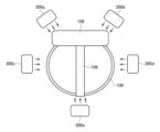
図8は、HMD100に取り付けられるファン装置の別の例を示す。図8は、HMD100を装着したユーザを頭頂部側から見た模式図である。図8に示すファン装置は4つのファンを有し、具体的には、ユーザの顔の正面に風を供給するファン300aと、ユーザの顔の正面に風を供給するファン300bと、ユーザの顔の左側面に風を供給するファン300cと、ユーザの顔の右側面に風を供給するファン300dとを備える。図8に示すファン300aは、主としてユーザの顔の正面左側に風を供給し、ファン300bは、主としてユーザの顔の正面右側に風を供給する。図8に示すファン装置は、ファン300a、300b、300c、300dを備え、ファン300a、300b、300c、300dのそれぞれの回転速度を調整することで、ユーザの顔の全面(HMD100で覆われている部分は除く)に様々な向きの風をあてることができる。
図9は、HMD100に取り付けられるファン装置の別の例を示す。図9は、HMD100を装着したユーザを頭頂部側から見た模式図である。図9に示すファン装置は4つのファンを有し、具体的には、ユーザの顔の正面に風を供給するファン300aと、ユーザの顔の左側面に風を供給するファン300bと、ユーザの顔の右側面に風を供給するファン300cと、ユーザの頭部の背面ないしは首の背面に風を供給するファン300dとを備える。図9に示すファン300dは、ユーザの頭部ないしは首の真後ろに風を供給する。図9に示すファン装置は、ファン300a、300b、300c、ファン300dを備え、ファン300a、300b、300c、300dのそれぞれの回転速度を調整することで、ユーザの顔の全面(HMD100で覆われている部分は除く)と、ユーザの頭部ないしは首の背面に様々な向きの風をあてることができる。
図10は、HMD100に取り付けられるファン装置の別の例を示す。図10は、HMD100を装着したユーザを頭頂部側から見た模式図である。図10に示すファン装置は5つのファンを有し、具体的には、ユーザの顔の正面に風を供給するファン300aと、ユーザの顔の正面に風を供給するファン300bと、ユーザの顔の左側面に風を供給するファン300cと、ユーザの顔の右側面に風を供給するファン300dと、ユーザの頭部の背面ないしは首の背面に風を供給するファン300eとを備える。図10に示すファン300aは、主としてユーザの顔の正面左側に風を供給し、ファン300bは、主としてユーザの顔の正面右側に風を供給する。図10に示すファン装置は、ファン300a、300b、300c、300d、300eを備え、ファン300a、300b、300c、300d、300eのそれぞれの回転速度を調整することで、ユーザの顔の全面(HMD100で覆われている部分は除く)と、ユーザの頭部ないしは首の背面に様々な向きの風をあてることができる。
図11は、HMD100に取り付けられるファン装置の別の例を示す。図11は、HMD100を装着したユーザを頭頂部側から見た模式図である。図11に示すファン装置は6つのファンを有し、具体的には、ユーザの顔の正面に風を供給するファン300aと、ユーザの顔の正面に風を供給するファン300bと、ユーザの顔の左側面に風を供給するファン300cと、ユーザの顔の右側面に風を供給するファン300dと、ユーザの頭部の背面ないしは首の背面に風を供給するファン300eと、ユーザの頭部の背面ないしは首の背面に風を供給するファン300fとを備える。図11に示すファン300aは、主としてユーザの顔の正面左側に風を供給し、ファン300bは、主としてユーザの顔の正面右側に風を供給し、ファン300eは、主としてユーザの頭部ないしは首の背面左側に風を供給し、ファン300fは、主としてユーザの頭部ないしは首の背面右側に風を供給する。図11に示すファン装置は、ファン300a、300b、300c、300d、300e、300fを備え、ファン300a、300b、300c、300d、300e、300fのそれぞれの回転速度を調整することで、ユーザの顔の全面(HMD100で覆われている部分は除く)と、ユーザの頭部ないしは首の背面に様々な向きの風をあてることができる。
図12は、ファン装置310が固定具330を介してHMD100に取り付けられた状態を示す。実施例のファン装置310は、ユーザに風を供給するファン300を有するファンユニットを少なくとも3つ備える。図12に示すファン装置310は、図8に示すファン配置構成を実現し、したがってユーザの顔の正面左側に風を供給するファン300aを有するファンユニット320aと、ユーザの顔の正面右側に風を供給するファン300bを有するファンユニット320bと、ユーザの顔の左側面に風を供給するファン300cを有するファンユニット320cと、ユーザの顔の右側面に風を供給するファン300dを有するファンユニット320d(図示せず)とを備える。ファンユニット320a、320b、320c、320dは、それぞれ固定具330に連結支持される連結部322a、322b、322c、322d(図示せず)を備える。以下、複数のファンユニット320a~320dを特に区別しない場合は、単に「ファンユニット320」と呼び、連結部322a~322dを特に区別しない場合は、単に「連結部322」と呼ぶこともある。なお図12に示すファン装置310は例示であって、ユーザの顔の正面に風を供給するファンは、図7に示すように1つであってもよく、またユーザの頭部または首の後ろ側に風を供給するファンが、図9~図11に示すように別途設けられてもよい。
固定具330は、ファン装置310をHMD100に取り付けるための部品であって、複数の部材により構成される。固定具330の部材は、剛性の高い筐体108や頭部周囲を固定する装着部品106に取り付けられる。固定具330は、ファンユニット320の連結部322を支持するための構造を備え、連結部322は、固定具330に支持される。HMD100がトラッキング機能などの各種機能を搭載している場合、固定具330は、HMD100の各種機能を阻害しないようにHMD100に取り付けられ、またファンユニット320は、HMD100の各種機能を阻害しないように固定具330に支持されることが好ましい。
この例で固定具330は、ユーザの顔の正面左側にファン300aを対向させる位置にファンユニット320aを支持し、ユーザの顔の正面右側にファン300bを対向させる位置にファンユニット320bを支持し、ユーザの顔の左側面にファン300cを対向させる位置にファンユニット320cを支持し、ユーザの顔の右側面にファン300dを対向させる位置にファンユニット320d(図示せず)を支持する。図示されるようにファンユニット320aおよび320bは、筐体108に固定具330を介して間接的に取り付けられ、ファンユニット320cおよび320dは、装着部品106に固定具330を介して間接的に取り付けられる。なおHMD100が連結部322を支持するための構造を備えている場合、連結部322は、固定具330を介することなく、HMD100に直接支持されてよい。また連結部322の端部にクリップが設けられ、ファンユニット320は、クリップによってHMD100に取り付けられてもよい。
図13は、ファンユニットの機能ブロックを示す。ファンユニット320は、ファン300、制御部350、通信部352、姿勢変更機構354および位置変更機構356を備える。姿勢変更機構354は、ファン300の向きを変更する機構であり、たとえばサーボモータを有してファン300の向きを所望に調整する機能を備える。位置変更機構356は、ファン300とユーザの間隔を変更する機構であり、たとえばラックアンドピニオンを有して、ファン300をユーザに対して近づけたり、遠ざけたりする機能を備える。通信部352は、情報処理装置10から、ファンユニット320を駆動制御するための制御信号を受信する。通信部352は、情報処理装置10の通信部202とケーブルで接続されてよいが、既知の無線通信プロトコルで接続されることが好ましい。ファンユニット320と情報処理装置10とが無線接続することで、ケーブルの取り回しの煩わしさを解消でき、ユーザビリティを高めることが可能となる。制御部350は、情報処理装置10から受信した制御信号にもとづいて、ファン300、姿勢変更機構354および/または位置変更機構356を駆動制御する。情報処理装置10は、ゲームの状況に応じた制御信号を生成して、ファンユニット320に送信する。
なお姿勢変更機構354および/または位置変更機構356は、ファン装置310を構成する複数のファンユニット320の全てが備える必要はなく、少なくとも1つのファンユニット320が備えてよい。たとえば図7に示すファン配置が採用される場合、ファン300aを有するファンユニット320が姿勢変更機構354を有し、ファン300b、300cを有するファンユニット320が位置変更機構356を有してよい。このときファン300b、300cを有するファンユニット320は、さらに姿勢変更機構354を有してもよい。姿勢変更機構354および/または位置変更機構356は、ユーザに供給する風のバリエーションを増やす目的で、適宜ファンユニット320に組み込まれてよい。
図4に戻って、プレイヤキャラクタ制御部222は、ユーザの操作入力にもとづいて3次元仮想空間内におけるプレイヤキャラクタの動きを制御する。風向特定部230は、仮想空間内のプレイヤキャラクタの位置における風向きを特定する。具体的に風向特定部230は、仮想空間の少なくとも2つの位置において設定された風向きを示す情報をもとに、プレイヤキャラクタの位置における風向きを特定する機能を有する。
実施例のゲームにおいて、仮想空間である洞窟は、複数の部分空間に分割されている。なお洞窟の全ての領域が部分空間に分割されている必要はなく、少なくともスタートからゴールまでのルートを構成する洞窟の領域が部分空間に分割されていればよい。実施例において部分空間は、ユーザに風を供給することを目的として設定される領域である。プレイヤキャラクタが部分空間を移動中、ユーザは、ファン装置310から進むべき方向を示す風を供給されることで、プレイヤキャラクタの正しい移動方向を推測する。
図14は、複数の部分空間の例を示す。この例では、スタートからゴールまでのルートが、複数の部分空間50a~50i(以下、特に区別しない場合は「部分空間50」と呼ぶ)に分割されている。この例では、行き止まりとなるルートに部分空間は設定されていないが、変形例では、行き止まりとなるルートにも部分空間が設定されてよい。
部分空間50は直方体の形状を有し、3次元形状の洞窟を包含するように設定されてよい。隣り合う部分空間50は重複した領域を有してよく、複数の部分空間50により、スタートからゴールまでの洞窟の領域がカバーされる。部分空間50には、当該部分空間50内における風向きを定めるための風パラメータが設定されている。風パラメータは、部分空間50の少なくとも2つの位置における風向きを示す情報を含む。風向特定部230は、部分空間50の少なくとも2つの位置において設定された風向きを示す情報をもとに、当該少なくとも2つの位置の間における風向きを補間して導出することで、プレイヤキャラクタの位置における風向きを特定する。部分空間50における風パラメータは、部分空間50の入口と出口において設定されていてよい。
図15は、部分空間50aに設定されている風パラメータの例を示す。部分空間50aの入口には、入口の風向きを示す風パラメータ52が設定されており、部分空間50aの出口には、出口の風向きを示す風パラメータ54が設定されている。なお図15には、風パラメータ52、54が、矢印の向きにより2次元的な風向きを示すように描かれているが、実際の部分空間50aは3次元の直方体形状を有しているため、風パラメータ52、54は3次元的な風向きを示してよい。
プレイヤキャラクタが部分空間50aに存在しているとき、風向特定部230は、部分空間50aにおける風パラメータ52、54にもとづいて、部分空間50a内のプレイヤキャラクタの位置における風向きを特定する。具体的に風向特定部230は、風パラメータ52、54により示される風向きをもとに、部分空間50aの入口と出口の間の任意の位置における風向きを補間して導出する機能を有する。風向特定部230は、プレイヤキャラクタ制御部222から部分空間50aにおけるプレイヤキャラクタの位置を取得すると、部分空間50aの入口における風向きと出口における風向きとから、当該位置における風向きを補間して特定してよい。
図16は、プレイヤキャラクタの位置において特定された風向きを示す。
図16は、プレイヤキャラクタの位置において特定された風向きを示す。
図17は、部分空間50aを3次元的に表現した図を示す。風向特定部230は、部分空間50aの入口における風パラメータ52と、出口における風パラメータ54から、プレイヤキャラクタの位置における風向きを特定する。部分空間50aにおいて、風パラメータ52および風パラメータ54は、直方体の対向面に設定されている。ここで風パラメータ52をベクトルWE、風パラメータ54をベクトルWS、部分空間50aの入口から出口までの間の距離をL、プレイヤキャラクタの位置と出口までの間の距離をlとすると、プレイヤキャラクタの位置における風向きは、以下の数式(1)のように表現されてよい。

ここでt=l/Lである。
図18は、部分空間50dに設定されている風パラメータの例を示す。部分空間50dの入口には、入口の風向きを示す風パラメータ56が設定されており、部分空間50dの出口には、出口の風向きを示す風パラメータ58が設定されている。なお図18においても、風パラメータ56、58が、矢印の向きにより2次元的な風向きを示すように描かれているが、実際の部分空間50dは3次元形状を有しているため、風パラメータ56、58は3次元的な風向きを示してよい。
図15に示す部分空間50aにおいては、風パラメータ52、54が直方体の対向面に設定されているが、部分空間50dにおいては、風パラメータ56、58が、直方体の任意の面に設定されている。なお風パラメータは、直方体の面に設定されるだけでなく、直方体の内部において設定されてもよい。
プレイヤキャラクタが部分空間50dに存在しているとき、風向特定部230は、部分空間50dにおける風パラメータ56、58にもとづいて、部分空間50d内のプレイヤキャラクタの位置における風向きを特定する。具体的に風向特定部230は、風パラメータ56、58により示される風向きをもとに、部分空間50dの入口と出口の間の任意の位置における風向きを補間して導出する機能を有する。風向特定部230は、プレイヤキャラクタ制御部222から部分空間50dにおけるプレイヤキャラクタの位置を取得すると、部分空間50dの入口における風向きと出口における風向きとから、当該位置における風向きを補間して特定してよい。
図19は、プレイヤキャラクタの位置において特定された風向きを示す。
図19は、プレイヤキャラクタの位置において特定された風向きを示す。
ゲームプレイ中、風向特定部230は、常にプレイヤキャラクタの位置における風向きを特定し、制御信号生成部234は、特定した風向きにもとづいて、HMD100に取り付けられた少なくとも3つのファン300のそれぞれを駆動するための制御信号を生成する。制御信号生成部234は、HMD100に取り付けられている複数のファン300の配置構成を認識しており、たとえば図7~図11に示すように複数のファン300の配置構成に選択肢がある場合、ユーザは、選択されたファン300の配置構成を事前に制御信号生成部234に登録しておくことが好ましい。
制御信号生成部234は、プレイヤキャラクタの視線方向と、特定された風向きとの相対的な角度を導出する。制御信号生成部234は、プレイヤキャラクタ制御部222からプレイヤキャラクタの視線方向を取得し、風向特定部230から、プレイヤキャラクタの位置における風向きを取得する。なお制御信号生成部234は、姿勢特定部228からユーザの視線方向を、プレイヤキャラクタの視線方向として取得してもよい。
図20は、プレイヤキャラクタの視線方向Hと風の向きWとの相対的な角度θを示す。ここで視線方向Hとファン300aの送風方向の角度はα1、視線方向Hとファン300bの送風方向の角度はα2、視線方向Hとファン300cの送風方向の角度はα3、視線方向Hとファン300dの送風方向の角度はα4となるように、ファン300a~300dが配置されているものとする。ここで風の風速を所定の風速|W|とすると、制御信号生成部234は、各ファン300から出力する風の風速wnを、以下の数式(2)により導出する。
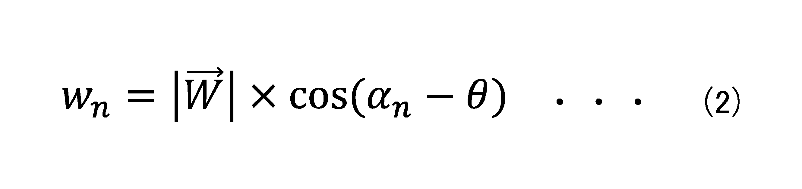
制御信号生成部234は、各ファン300が出力する風速wnを導出すると、各ファン300が風速wnで風を出力するための制御信号を生成する。たとえばファン300がPWM制御信号により駆動される場合、制御信号生成部234は、PWM制御信号のパルス幅を調整して、各ファン300の回転速度を制御してよい。なお数式(2)により、0未満の風速wnが導出されたファン300については、制御信号生成部234は、当該ファン300の回転を禁止してよい。
なお、風速wn<0の場合、制御信号生成部234は、当該ファン300を逆回転させる制御信号を生成してもよい。たとえばユーザの頭部に対して左側から風を供給するべく、制御信号生成部234が、ファン300cを正回転させる制御信号を生成するとき、制御信号生成部234は同時に、ファン300dを逆回転させる制御信号を生成してよい。特に、ファン300cとファン300dとがユーザ頭部を挟んで対向して配置されているとき、ファン300cとファン300dとを互いに反対となる向きで回転させることで、頭部に対して左方向または右方向の風をユーザに顕著に感じさせることが可能となる。
供給部240は、制御信号生成部234が生成した制御信号を通信部202からファンユニット320に送信する。実施例のファン装置310では、複数のファンユニット320のそれぞれが独立して動作し、各ファンユニット320において、通信部352が自身宛の制御信号を受信すると、制御部350は、制御信号にもとづいてファン300を駆動する。これによりファン装置310は複数のファン300を回転して、プレイヤキャラクタが進むべき方向を示す風をユーザに供給でき、ユーザは、風向きを感じることで、プレイヤキャラクタが進むべき方向を推測できる。なおファン装置310においては、ファンユニット320が独立して動作するのではなく、ファン装置310が、複数のファン300を統括して制御する制御部350を備えるように構成されてもよい。
なお以上は、風速|W|が所定値である場合について説明した。風パラメータは、部分空間50の少なくとも2つの位置における風の強さ(風速)を示す情報を含んでもよい。この場合、風速特定部232が、部分空間50の少なくとも2つの位置において設定された風速を示す情報をもとに、当該少なくとも2つの位置の間における風速を補間して導出する機能を備えてよい。この補間処理により、風速特定部232は、プレイヤキャラクタの位置における風の強さ(風速)を特定してよい。
この場合、図17を参照して、部分空間50aの入口に設定された風パラメータ52は、入口の風向きを示すとともに、入口の風速も示し、部分空間50aの出口に設定された風パラメータ54は、出口の風向きを示すとともに、出口の風速も示す。現実の洞窟内では、通常、広い洞窟における風速は小さく、狭い洞窟における風速は大きくなる傾向がある。そこで風パラメータ52、54に、風速の情報を含ませることで、ユーザに、洞窟の形状の変化を感じさせることが可能となる。具体的には、風パラメータ52であるベクトルWE、風パラメータ54であるベクトルWSに風速を示す情報(ベクトルの大きさ)をもたせることで、数式(1)を用いて、プレイヤキャラクタの位置における風向きおよび風速を特定することが可能となる。
以上、本開示を実施例をもとに説明した。上記実施例は例示であり、それらの各構成要素や各処理プロセスの組合せにいろいろな変形例が可能なこと、またそうした変形例も本開示の範囲にあることは当業者に理解されるところである。実施例では、ファン装置310が、複数の独立したファンユニット320を有することを説明したが、ファン装置310は、複数の一体化したファンユニット320を有してもよい。
実施例では、風速特定部232が、部分空間50に設定された風パラメータにしたがって風速を決定することを説明したが、変形例では、風速特定部232が、プレイヤキャラクタの移動速度に応じて風速を決定してもよい。たとえばプレイヤキャラクタの移動速度が相対的に大きければ、風速特定部232は、風速を相対的に大きく決定し、プレイヤキャラクタの移動速度が相対的に小さければ、風速特定部232は、風速を相対的に小さく決定してよい。なお風速特定部232は、部分空間50に設定された風パラメータと、プレイヤキャラクタの移動速度の双方を加味して、プレイヤキャラクタの位置における風速を決定してよい。
変形例では、制御部350が、姿勢変更機構354を用いてファン300の向きを調整して、ユーザの視線方向とファン300の送風方向との相対的な角度が、プレイヤキャラクタの視線方向Hと風の向きWとの相対的な角度θとなるようにしてもよい。ファン装置310を構成する全てのファンユニット320が姿勢変更機構354を搭載する場合、制御部350は、ユーザの視線方向(HMDの正面方向)とファン300の送風方向とが角度θとなるようにファン300の向きを調整することで、ユーザに正確な風向きを提示することが可能となる。この変形例で制御信号生成部234は、角度θを示す制御信号を生成し、制御部350は、当該制御信号にもとづいて、ファン300の向きを調整する。
変形例では、制御部350が、位置変更機構356を用いてファン300とユーザとの間隔を変更して、風のあてかたを調整してもよい。ユーザに近い位置から風が供給されると、ユーザは顔の狭い範囲で風を感じ、ユーザに遠い位置から風が供給されると、ユーザは顔の広い範囲で風を感じることになる。この感じ方の違いを利用して、制御信号生成部234は、風向きをはっきりと提示したい状況においては位置変更機構356によりファン300とユーザの間隔を近づける制御信号を生成してよい。また逆に、風向きをぼんやりと提示したい状況においては、制御信号生成部234は、位置変更機構356によりファン300とユーザの間隔を遠ざける制御信号を生成してよい。
ファン300が供給する風は、その温度を調整可能であってよい。たとえばペルチェ素子や電熱線を用いることで、ファン300は、暖かい風を供給できる。風の温度を調整可能とすることで、ユーザに対して、仮想空間における環境の変化を提示することが可能となる。
本開示は、以下の態様を含んでよい。
[項目1]
ユーザの頭部に装着されるウェアラブルデバイスに取り付けられるファン装置であって、
ユーザの顔の正面に風を供給するファンを有する第1ファンユニットと、
ユーザの顔の左側面に風を供給するファンを有する第2ファンユニットと、
ユーザの顔の右側面に風を供給するファンを有する第3ファンユニットと、
を備えるファン装置。
[項目2]
前記ウェアラブルデバイスは、当該ウェアラブルデバイスをユーザ頭部に装着させる装着部品と、当該ウェアラブルデバイスがユーザ頭部に装着された状態においてユーザの目を覆う筐体とを備えており、
前記第1ファンユニットは、前記筐体に取り付けられ、
前記第2ファンユニットおよび前記第3ファンユニットは、前記装着部品に取り付けられる、
ことを特徴とする項目1に記載のファン装置。
[項目3]
前記第1ファンユニット、前記第2ファンユニット、前記第3ファンユニットの少なくとも1つは、前記ファンの向きを変更する機構を有する、
ことを特徴とする項目1に記載のファン装置。
[項目4]
前記第1ファンユニット、前記第2ファンユニット、前記第3ファンユニットの少なくとも1つは、前記ファンとユーザの間隔を変更する機構を有する、
ことを特徴とする項目1に記載のファン装置。
[項目5]
前記第1ファンユニットのファンは、主としてユーザの顔の正面左側に風を供給し、
前記ファン装置は、さらに、主としてユーザの顔の正面右側に風を供給するファンを有する第4ファンユニットを備える、
ことを特徴とする項目1に記載のファン装置。
[項目6]
ユーザの頭部に装着されるウェアラブルデバイスであって、
ユーザの顔の正面に風を供給するファンを有する第1ファンユニットと、
ユーザの顔の左側面に風を供給するファンを有する第2ファンユニットと、
ユーザの顔の右側面に風を供給するファンを有する第3ファンユニットと、
を備えるウェアラブルデバイス。
[項目7]
情報処理装置のコンピュータにおいて実行されるプログラムを記録した記録媒体であって、前記プログラムは前記コンピュータに、
ユーザの操作入力にもとづいてプレイヤキャラクタの動きを制御する機能と、
仮想空間内のプレイヤキャラクタの位置における風向きを特定する機能と、
特定した風向きにもとづいて、ウェアラブルデバイスに取り付けられた少なくとも3つのファンのそれぞれを駆動するための制御信号を生成する機能と、
前記制御信号を送信する機能と、
を実現させるための記録媒体。
[項目8]
風向きを特定する機能は、仮想空間の少なくとも2つの位置において設定された風向きを示す情報をもとに、プレイヤキャラクタの位置における風向きを特定する機能を含む、
ことを特徴とする項目7に記載の記録媒体。
[項目9]
風向きを特定する機能は、仮想空間の少なくとも2つの位置において設定された風向きを示す情報をもとに、当該少なくとも2つの位置の間における風向きを補間して導出することで、プレイヤキャラクタの位置における風向きを特定する機能を含む、
ことを特徴とする項目8に記載の記録媒体。
[項目10]
風向きを示す情報は、仮想空間の入口と出口において設定されている、
ことを特徴とする項目8に記載の記録媒体。
[項目11]
前記コンピュータに、
仮想空間内におけるプレイヤキャラクタの位置における風の強さを特定する機能、
を実現させるための項目7に記載の記録媒体。
[項目12]
制御信号を生成する機能は、特定した風の強さにもとづいて、少なくとも3つのファンのそれぞれを駆動するための制御信号を生成する機能を含む、
ことを特徴とする項目11に記載の記録媒体。
[項目13]
制御信号を生成する機能は、ユーザの顔の正面に風を供給する第1ファンと、ユーザの顔の左側面に風を供給する第2ファンと、ユーザの顔の右側面に風を供給する第3ファンのそれぞれを駆動するための制御信号を生成する機能を含む、
ことを特徴とする項目7に記載の記録媒体。
[項目14]
制御信号を生成する機能は、第2ファンを正回転させる制御信号を生成するとき、同時に第3ファンを逆回転させる制御信号を生成する機能を含む、
ことを特徴とする項目13に記載の記録媒体。
[項目1]
ユーザの頭部に装着されるウェアラブルデバイスに取り付けられるファン装置であって、
ユーザの顔の正面に風を供給するファンを有する第1ファンユニットと、
ユーザの顔の左側面に風を供給するファンを有する第2ファンユニットと、
ユーザの顔の右側面に風を供給するファンを有する第3ファンユニットと、
を備えるファン装置。
[項目2]
前記ウェアラブルデバイスは、当該ウェアラブルデバイスをユーザ頭部に装着させる装着部品と、当該ウェアラブルデバイスがユーザ頭部に装着された状態においてユーザの目を覆う筐体とを備えており、
前記第1ファンユニットは、前記筐体に取り付けられ、
前記第2ファンユニットおよび前記第3ファンユニットは、前記装着部品に取り付けられる、
ことを特徴とする項目1に記載のファン装置。
[項目3]
前記第1ファンユニット、前記第2ファンユニット、前記第3ファンユニットの少なくとも1つは、前記ファンの向きを変更する機構を有する、
ことを特徴とする項目1に記載のファン装置。
[項目4]
前記第1ファンユニット、前記第2ファンユニット、前記第3ファンユニットの少なくとも1つは、前記ファンとユーザの間隔を変更する機構を有する、
ことを特徴とする項目1に記載のファン装置。
[項目5]
前記第1ファンユニットのファンは、主としてユーザの顔の正面左側に風を供給し、
前記ファン装置は、さらに、主としてユーザの顔の正面右側に風を供給するファンを有する第4ファンユニットを備える、
ことを特徴とする項目1に記載のファン装置。
[項目6]
ユーザの頭部に装着されるウェアラブルデバイスであって、
ユーザの顔の正面に風を供給するファンを有する第1ファンユニットと、
ユーザの顔の左側面に風を供給するファンを有する第2ファンユニットと、
ユーザの顔の右側面に風を供給するファンを有する第3ファンユニットと、
を備えるウェアラブルデバイス。
[項目7]
情報処理装置のコンピュータにおいて実行されるプログラムを記録した記録媒体であって、前記プログラムは前記コンピュータに、
ユーザの操作入力にもとづいてプレイヤキャラクタの動きを制御する機能と、
仮想空間内のプレイヤキャラクタの位置における風向きを特定する機能と、
特定した風向きにもとづいて、ウェアラブルデバイスに取り付けられた少なくとも3つのファンのそれぞれを駆動するための制御信号を生成する機能と、
前記制御信号を送信する機能と、
を実現させるための記録媒体。
[項目8]
風向きを特定する機能は、仮想空間の少なくとも2つの位置において設定された風向きを示す情報をもとに、プレイヤキャラクタの位置における風向きを特定する機能を含む、
ことを特徴とする項目7に記載の記録媒体。
[項目9]
風向きを特定する機能は、仮想空間の少なくとも2つの位置において設定された風向きを示す情報をもとに、当該少なくとも2つの位置の間における風向きを補間して導出することで、プレイヤキャラクタの位置における風向きを特定する機能を含む、
ことを特徴とする項目8に記載の記録媒体。
[項目10]
風向きを示す情報は、仮想空間の入口と出口において設定されている、
ことを特徴とする項目8に記載の記録媒体。
[項目11]
前記コンピュータに、
仮想空間内におけるプレイヤキャラクタの位置における風の強さを特定する機能、
を実現させるための項目7に記載の記録媒体。
[項目12]
制御信号を生成する機能は、特定した風の強さにもとづいて、少なくとも3つのファンのそれぞれを駆動するための制御信号を生成する機能を含む、
ことを特徴とする項目11に記載の記録媒体。
[項目13]
制御信号を生成する機能は、ユーザの顔の正面に風を供給する第1ファンと、ユーザの顔の左側面に風を供給する第2ファンと、ユーザの顔の右側面に風を供給する第3ファンのそれぞれを駆動するための制御信号を生成する機能を含む、
ことを特徴とする項目7に記載の記録媒体。
[項目14]
制御信号を生成する機能は、第2ファンを正回転させる制御信号を生成するとき、同時に第3ファンを逆回転させる制御信号を生成する機能を含む、
ことを特徴とする項目13に記載の記録媒体。
本開示は、ウェアラブルデバイスを頭部に装着したユーザに風を供給する技術分野に利用できる。
1・・・情報処理システム、2・・・ネットワーク、4・・・出力装置、6・・・入力装置、8・・・AP、10・・・情報処理装置、11・・・記録装置、50・・・部分空間、52,54,56,58・・・風パラメータ、100・・・HMD、102・・・出力部、104・・・固定部、106・・・装着部品、108・・・筐体、120・・・制御部、122・・・記憶部、124・・・IMU、126・・・マイク、128・・・通信制御部、130・・・表示パネル、130a・・・左目用表示パネル、130b・・・右目用表示パネル、132・・・音声出力部、200・・・処理部、202・・・通信部、210・・・取得部、220・・・ゲーム実行部、222・・・プレイヤキャラクタ制御部、224・・・ゲーム画像生成部、226・・・ゲーム音生成部、228・・・姿勢特定部、230・・・風向特定部、232・・・風速特定部、234・・・制御信号生成部、240・・・供給部、300,300a,300b,300c,300d,300e,300f・・・ファン、310・・・ファン装置、320,320a,320b,320c,320d・・・ファンユニット、330・・・固定具、350・・・制御部、352・・・通信部、354・・・姿勢変更機構、356・・・位置変更機構。
Claims (14)
- ユーザの頭部に装着されるウェアラブルデバイスに取り付けられるファン装置であって、
ユーザの顔の正面に風を供給するファンを有する第1ファンユニットと、
ユーザの顔の左側面に風を供給するファンを有する第2ファンユニットと、
ユーザの顔の右側面に風を供給するファンを有する第3ファンユニットと、
を備えるファン装置。 - 前記ウェアラブルデバイスは、当該ウェアラブルデバイスをユーザ頭部に装着させる装着部品と、当該ウェアラブルデバイスがユーザ頭部に装着された状態においてユーザの目を覆う筐体とを備えており、
前記第1ファンユニットは、前記筐体に取り付けられ、
前記第2ファンユニットおよび前記第3ファンユニットは、前記装着部品に取り付けられる、
ことを特徴とする請求項1に記載のファン装置。 - 前記第1ファンユニット、前記第2ファンユニット、前記第3ファンユニットの少なくとも1つは、前記ファンの向きを変更する機構を有する、
ことを特徴とする請求項1に記載のファン装置。 - 前記第1ファンユニット、前記第2ファンユニット、前記第3ファンユニットの少なくとも1つは、前記ファンとユーザの間隔を変更する機構を有する、
ことを特徴とする請求項1に記載のファン装置。 - 前記第1ファンユニットのファンは、主としてユーザの顔の正面左側に風を供給し、
前記ファン装置は、さらに、主としてユーザの顔の正面右側に風を供給するファンを有する第4ファンユニットを備える、
ことを特徴とする請求項1に記載のファン装置。 - ユーザの頭部に装着されるウェアラブルデバイスであって、
ユーザの顔の正面に風を供給するファンを有する第1ファンユニットと、
ユーザの顔の左側面に風を供給するファンを有する第2ファンユニットと、
ユーザの顔の右側面に風を供給するファンを有する第3ファンユニットと、
を備えるウェアラブルデバイス。 - 情報処理装置のコンピュータにおいて実行されるプログラムであって、前記コンピュータに、
ユーザの操作入力にもとづいてプレイヤキャラクタの動きを制御する機能と、
仮想空間内のプレイヤキャラクタの位置における風向きを特定する機能と、
特定した風向きにもとづいて、ウェアラブルデバイスに取り付けられた少なくとも3つのファンのそれぞれを駆動するための制御信号を生成する機能と、
前記制御信号を送信する機能と、
を実現させるためのプログラム。 - 風向きを特定する機能は、仮想空間の少なくとも2つの位置において設定された風向きを示す情報をもとに、プレイヤキャラクタの位置における風向きを特定する機能を含む、
ことを特徴とする請求項7に記載のプログラム。 - 風向きを特定する機能は、仮想空間の少なくとも2つの位置において設定された風向きを示す情報をもとに、当該少なくとも2つの位置の間における風向きを補間して導出することで、プレイヤキャラクタの位置における風向きを特定する機能を含む、
ことを特徴とする請求項8に記載のプログラム。 - 風向きを示す情報は、仮想空間の入口と出口において設定されている、
ことを特徴とする請求項8に記載のプログラム。 - 前記コンピュータに、
仮想空間内におけるプレイヤキャラクタの位置における風の強さを特定する機能、
を実現させるための請求項7に記載のプログラム。 - 制御信号を生成する機能は、特定した風の強さにもとづいて、少なくとも3つのファンのそれぞれを駆動するための制御信号を生成する機能を含む、
ことを特徴とする請求項11に記載のプログラム。 - 制御信号を生成する機能は、ユーザの顔の正面に風を供給する第1ファンと、ユーザの顔の左側面に風を供給する第2ファンと、ユーザの顔の右側面に風を供給する第3ファンのそれぞれを駆動するための制御信号を生成する機能を含む、
ことを特徴とする請求項7に記載のプログラム。 - 制御信号を生成する機能は、第2ファンを正回転させる制御信号を生成するとき、同時に第3ファンを逆回転させる制御信号を生成する機能を含む、
ことを特徴とする請求項13に記載のプログラム。
Priority Applications (1)
| Application Number | Priority Date | Filing Date | Title |
|---|---|---|---|
| PCT/JP2023/045625 WO2025134253A1 (ja) | 2023-12-20 | 2023-12-20 | ファン装置、ウェアラブルデバイスおよびファンを駆動するプログラム |
Applications Claiming Priority (1)
| Application Number | Priority Date | Filing Date | Title |
|---|---|---|---|
| PCT/JP2023/045625 WO2025134253A1 (ja) | 2023-12-20 | 2023-12-20 | ファン装置、ウェアラブルデバイスおよびファンを駆動するプログラム |
Publications (1)
| Publication Number | Publication Date |
|---|---|
| WO2025134253A1 true WO2025134253A1 (ja) | 2025-06-26 |
Family
ID=96137815
Family Applications (1)
| Application Number | Title | Priority Date | Filing Date |
|---|---|---|---|
| PCT/JP2023/045625 Pending WO2025134253A1 (ja) | 2023-12-20 | 2023-12-20 | ファン装置、ウェアラブルデバイスおよびファンを駆動するプログラム |
Country Status (1)
| Country | Link |
|---|---|
| WO (1) | WO2025134253A1 (ja) |
Citations (2)
| Publication number | Priority date | Publication date | Assignee | Title |
|---|---|---|---|---|
| WO2017002435A1 (ja) * | 2015-07-01 | 2017-01-05 | ソニー株式会社 | 情報処理装置、情報処理方法、およびプログラム |
| WO2018163700A1 (ja) * | 2017-03-07 | 2018-09-13 | ソニー株式会社 | コンテンツ提示システム、コンテンツ提示装置及び風提示装置 |
-
2023
- 2023-12-20 WO PCT/JP2023/045625 patent/WO2025134253A1/ja active Pending
Patent Citations (2)
| Publication number | Priority date | Publication date | Assignee | Title |
|---|---|---|---|---|
| WO2017002435A1 (ja) * | 2015-07-01 | 2017-01-05 | ソニー株式会社 | 情報処理装置、情報処理方法、およびプログラム |
| WO2018163700A1 (ja) * | 2017-03-07 | 2018-09-13 | ソニー株式会社 | コンテンツ提示システム、コンテンツ提示装置及び風提示装置 |
Non-Patent Citations (1)
| Title |
|---|
| S CARDIN, VEXO F, THALMANN D: "Head Mounted Wind", PROCEEDING OF THE 20TH ANNUAL CONFERENCE ON COMPUTER ANIMATION AND SOCIAL AGENTS (CASA2007), 15 May 2007 (2007-05-15), pages 101 - 108, XP055457221, Retrieved from the Internet <URL:http://web.cs.wpi.edu/~gogo/hive/papers/Cardin_CASA_2007.pdf> [retrieved on 20180307] * |
Similar Documents
| Publication | Publication Date | Title |
|---|---|---|
| US10313481B2 (en) | Information processing method and system for executing the information method | |
| US20180357817A1 (en) | Information processing method, program, and computer | |
| US20190116350A1 (en) | Orientation and/or position estimation system, orientation and/or position estimation method, and orientation and/or position estimation apparatus | |
| US20180189555A1 (en) | Method executed on computer for communicating via virtual space, program for executing the method on computer, and computer apparatus therefor | |
| JP6425846B1 (ja) | プログラム、情報処理装置、及び情報処理方法 | |
| JP2019128721A (ja) | ユーザの動きをアバタに反映するためのプログラム、当該プログラムを実行するための情報処理装置、およびアバタを含む映像を配信するための方法 | |
| JP2018056924A (ja) | 画像表示装置、及びこれを用いた仮想現実インタフェースデバイス | |
| JP7344716B2 (ja) | 情報処理システム、情報処理プログラム、情報処理装置および情報処理方法 | |
| JP2022171742A (ja) | プログラム、情報処理方法及び情報処理装置 | |
| JP2020004060A (ja) | プログラム、情報処理装置および方法 | |
| JP2019036122A (ja) | 情報処理方法、プログラム、およびコンピュータ | |
| JP7005406B2 (ja) | プログラム、情報処理装置、及び情報処理方法 | |
| JP2018194889A (ja) | 情報処理方法、コンピュータ及びプログラム | |
| TW201944365A (zh) | 增強第一身視角體驗的方法 | |
| JP6660321B2 (ja) | シミュレーションシステム及びプログラム | |
| JP6788129B2 (ja) | ズーム装置及び関連する方法 | |
| JP2018129692A (ja) | 頭部装着型表示装置及びシミュレーションシステム | |
| US20180246579A1 (en) | Method executed on computer for communicating via virtual space, program for executing the method on computer, and computer apparatus therefor | |
| JP6703578B2 (ja) | プログラム、方法及び情報処理装置 | |
| JP7037467B2 (ja) | プログラム、情報処理装置、及び情報処理方法 | |
| JP7313523B1 (ja) | プログラムおよび情報処理システム | |
| US10319346B2 (en) | Method for communicating via virtual space and system for executing the method | |
| JP2018026048A (ja) | 情報処理方法および当該情報処理方法をコンピュータに実行させるためのプログラム | |
| WO2023286191A1 (ja) | 情報処理装置および駆動データ生成方法 | |
| JP2022048172A (ja) | プログラム、情報処理装置、及び情報処理方法 |
Legal Events
| Date | Code | Title | Description |
|---|---|---|---|
| 121 | Ep: the epo has been informed by wipo that ep was designated in this application |
Ref document number: 23962174 Country of ref document: EP Kind code of ref document: A1 |