WO2025126540A1 - タイヤ走行性能測定装置 - Google Patents
タイヤ走行性能測定装置 Download PDFInfo
- Publication number
- WO2025126540A1 WO2025126540A1 PCT/JP2024/024809 JP2024024809W WO2025126540A1 WO 2025126540 A1 WO2025126540 A1 WO 2025126540A1 JP 2024024809 W JP2024024809 W JP 2024024809W WO 2025126540 A1 WO2025126540 A1 WO 2025126540A1
- Authority
- WO
- WIPO (PCT)
- Prior art keywords
- tire
- vehicle
- measurement target
- support
- running performance
- Prior art date
- Legal status (The legal status is an assumption and is not a legal conclusion. Google has not performed a legal analysis and makes no representation as to the accuracy of the status listed.)
- Pending
Links
Images


Classifications
-
- G—PHYSICS
- G01—MEASURING; TESTING
- G01M—TESTING STATIC OR DYNAMIC BALANCE OF MACHINES OR STRUCTURES; TESTING OF STRUCTURES OR APPARATUS, NOT OTHERWISE PROVIDED FOR
- G01M17/00—Testing of vehicles
- G01M17/007—Wheeled or endless-tracked vehicles
- G01M17/02—Tyres
Definitions
- the present invention relates to a tire running performance measuring device.
- This application claims priority based on Japanese Patent Application No. 2023-208859, filed in Japan on December 11, 2023, the entire contents of which are incorporated herein by reference.
- test tire a rail-type tire running performance measuring device that measures the running performance of a tire to be measured (hereinafter also referred to as "test tire”), in which a support that supports the test tire inside a housing is slid on a guide rail (for example, Non-Patent Document 1).
- the present invention aims to provide a tire running performance measurement device that can increase the range of tire sizes and running speeds that can be measured.
- a tire running performance measuring device for measuring the running performance of a test subject tire, comprising: Vehicles and A measurement target tire support tool that is configured separately from the vehicle and is attached to the vehicle and configured to support the measurement target tire; Equipped with The tire running performance measuring device, wherein the test object tire support tool is configured so as to be able to adjust the load applied to the test object tire.
- the present invention provides a tire running performance measuring device that can increase the range of tire sizes and running speeds that can be measured.
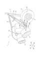
- FIG. 1 is a perspective view showing a tire running performance measuring device according to an embodiment of the present invention, as viewed from the rear right side.
- FIG. 2 is a perspective view showing the tire running performance measuring device of FIG. 1 as viewed from the rear left side.
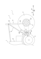
- FIG. 2 is a side view showing a schematic view of a portion of the tire running performance measuring device shown in FIG. 1 as seen from the left side.
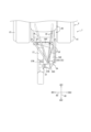
- 2 is a rear view showing the tire running performance measuring device of FIG. 1 as viewed from the rear side.
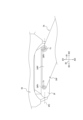
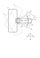
- FIG. 2 is a top view that shows a schematic view of a portion of the tire running performance measuring device of FIG. 1 as seen from above.
- FIG. FIG. 6 is a top view that shows a schematic enlarged view of a portion of FIG. 5 .
- FIG. 6 is a top view showing an enlarged view of a portion of FIG. 5 (however, a portion different from FIG. 6);
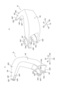
- FIG. FIG. 2 is a perspective view showing the swing arm of FIG. 1 ;
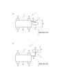
- 9(a) and 9(b) are top views each showing a schematic view of a different modified example of the tire running performance measuring device of the present invention as seen from above.
- the tire running performance measuring device can be used to measure the running performance of any type of tire, and can be suitably used, for example, to measure the running performance of tires for lunar rovers.
- the tire running performance measuring device 1 is configured to measure the running performance of a tire ET to be measured (hereinafter, also referred to as "measurement target tire ET").
- the measurement target tire ET may be any type of tire, and may be, for example, a lunar rover tire.
- a tire running performance measuring device 1 includes a vehicle V and a tire support S to be measured.
- the vehicle V may be any type of vehicle, preferably a four-wheeled vehicle.
- the vehicle V includes a vehicle body VB and a plurality of tires VT (four tires in this embodiment) mounted on the vehicle body VB (hereinafter, also referred to as "vehicle-mounted tires VT").
- the vehicle V may have any conventional vehicle configuration. It is preferable that the vehicle V is, for example, a lightweight vehicle (such as a buggy) suitable for soft ground, since this allows stable driving and measurement even on rough roads such as soft ground.
- the vehicle V is configured to automatically control the vehicle speed so as to maintain a desired vehicle speed while traveling. From the viewpoint of stable measurement at various locations and speeds, it is preferable to use a laser Doppler type vehicle speed sensor as the vehicle speed sensor. However, the vehicle V does not have to be configured to be able to automatically control the vehicle speed.
- the tire support S to be measured is configured separately from the vehicle V (and is therefore external to the vehicle V).
- the tire support S to be measured is attached to the body VB of the vehicle V.
- the tire support S to be measured is configured to support the tire ET to be measured so that the tire ET to be measured is maintained at a predetermined height and posture. During measurement (and therefore while the vehicle V is traveling), the tire ET to be measured is supported by the tire support S to be measured so that its tread surface is in contact with the road surface or the like.
- the tire running performance measuring device 1 is configured to roll a test tire ET connected to the vehicle V via a test tire support S on a road surface or the like (e.g., soft ground) while the vehicle V is running on the road surface or the like in response to driving by a driver and/or automatic driving, etc., and to measure various running performances (slip ratio, etc.) of the test tire ET during that time using various measuring devices (sensors, etc., not shown). It is preferable that the measuring device for measuring the running performance of the test target tire ET is not mounted on the vehicle V, and may be mounted on the test target tire support tool S, for example.
- the support depth direction AD and the support width direction BD fixed to the measurement target tire support S are defined.
- the support depth direction AD and the support width direction BD are parallel to the horizontal direction and perpendicular to each other.
- one side in the support depth direction AD is referred to as the "support depth direction first side AD1”
- the other side in the support depth direction AD is referred to as the "support depth direction second side AD2”.
- one side in the support width direction BD is referred to as the "support width direction first side BD1”
- the other side in the support width direction BD is referred to as the "support width direction second side BD2”.
- the support depth direction second side AD2 is the measurement target tire support S side when viewed from the vehicle V.
- each of these directions is indicated with an arrow.
- the support widthwise first side BD1 and the support widthwise second side BD2 may be reversed. That is, in this embodiment, the support widthwise first side BD1 is on the left side when the support depthwise first side AD1 is seen as the front side, but it may be on the right side when the support depthwise first side AD1 is seen as the front side.
- the right, left, front, and rear of vehicle V (as viewed from vehicle V) will be simply referred to as "right,”"left,””front,” and “rear,” respectively.
- the tire support S to be measured is located on the rear side with respect to the vehicle V. Therefore, in this embodiment, the support depth direction AD is the front-rear direction, the support depth direction first side AD1 is the front side, the support depth direction second side AD2 is the rear side, and the support width direction BD is the left-right direction. Note that, in this embodiment, the support width direction first side BD1 is the left side, and the support width direction second side BD2 is the right side.
- the tire support S to be measured may be located on any side (e.g., the left side, right side, or front side) with respect to the vehicle V.
- the support depth direction AD is the left-right direction
- the support depth direction second side AD2 is the right side
- the support width direction BD is the front-rear direction. It is preferable that the measurement target tire support S is located on the rear side with respect to the vehicle V, as in this embodiment.
- the tire support S to be measured is attached to the second side AD2 (rear side in this embodiment) of the vehicle body VB of the vehicle V in the support depth direction.
- the tire running performance measuring device 1 of this embodiment includes the vehicle V and the measurement target tire support S that is configured separately from the vehicle V and attached to the vehicle V so as to support the measurement target tire ET.
- This makes it possible to use a larger measurement target tire ET and perform measurement at a higher speed, unlike conventional rail-type devices, and ultimately increases the range of sizes of the measurement target tire ET and the running speeds that can be accommodated.
- conventional rail-type devices are basically limited to installation indoors
- the tire running performance measuring device 1 of this embodiment is configured to be movable by the vehicle V, so there are no restrictions on the place of use or storage, and it can be used anywhere, whether indoors or outdoors. Therefore, it can be used on a wide area such as a variety of grounds or vacant lots.
- the measurement target tire ET As another method for measuring the running performance of the measurement target tire ET, it is also possible to mount the measurement target tire ET on the vehicle body VB. In that case, it is sufficient if the type of the vehicle body VB and the type and size of each tire VT mounted thereon can be unified, but in reality, there are many cases where discrepancies occur, such as when the type of the vehicle body VB is different from the vehicle type suitable for the measurement target tire ET (for example, when the measurement target tire ET is for a lunar rover and the vehicle body VB is for a passenger car), or when the type and size of each remaining tire VT mounted on the vehicle body VB are different from the type and size of the measurement target tire ET (for example, when the measurement target tire ET is for a lunar rover and the remaining tires VT mounted on the vehicle body VB are for a passenger car), and in such cases, there is a risk that measurement cannot be performed under the intended conditions.
- the tire ET to be measured is independent of the vehicle V, so it is possible to use tires of a type and size as the tire ET to be measured that are significantly different from the type of the vehicle body VB of the vehicle V and the type and size of each tire VT.
- the measurement target tire support S is configured to adjust the load applied to the measurement target tire ET. More specifically, the measurement target tire support S is configured to adjust the load applied to the measurement target tire ET by adjusting the height of the rotation axis of the measurement target tire ET. By raising the height of the rotation axis of the measurement target tire ET while the tread surface of the measurement target tire ET is in contact with the road surface or the like, the load applied to the measurement target tire ET can be reduced, and for example, it is possible to reproduce the load state in an environment (e.g., the surface of the moon) where gravity is smaller than that of the earth.
- an environment e.g., the surface of the moon
- the measurement target tire support S which is configured separately from the vehicle V (i.e., outside the vehicle V), is configured to be able to adjust the load applied to the measurement target tire ET, so that the weight of the vehicle V is not applied to the measurement target tire ET.
- the load applied to the measurement target tire ET can be adjusted independently of the vehicle V, there is no need to adjust the weight of the vehicle V when adjusting the load applied to the measurement target tire ET, unlike the case where the measurement target tire ET is mounted on the vehicle body VB as described above. This makes it easy to adjust the load applied to the measurement target tire ET.
- the measurement target tire support S has a swing arm pivot shaft SP, a swing arm SA, a measurement target tire mounting part ST, a power cylinder SS, and one or more (in this embodiment, multiple) power cylinder fixing members SF.
- the swing arm pivot shaft SP is attached to the body VB of the vehicle V by fastening or the like.
- the swing arm pivot shaft SP is attached to a portion of the body VB on the second side AD2 in the support depth direction.
- the swing arm pivot shaft SP extends substantially horizontally, and more specifically, extends substantially in the support width direction BD ( Figures 5-6).
- the swing arm SA is made of a rigid body such as metal or resin, etc.
- the swing arm SA is configured to be swingable about a central axis SPC of a swing arm pivot shaft SP (FIGS. 1 to 3, 5 to 6, and 8). More specifically, the end of the swing arm SA on a first side AD1 in the support depth direction of the swing arm SA forms a pivot part SAP.
- the pivot part SAP forms a pivot mechanism with the swing arm pivot shaft SP and is configured to be swingable about a central axis SPC of the swing arm pivot shaft SP.
- the pivot part SAP of the swing arm SA extends substantially in the support width direction BD (FIGS. 5 to 6).
- the pivot part SAP is bifurcated by having a pair of opposing parts SAPF that face each other in the up-down direction (FIGS. 2 to 3 and 8).
- the pair of opposing parts SAPF are located on both the upper and lower sides of the swing arm pivot shaft SP.
- the pivot portion SAP has one or more (in this embodiment, multiple) fastening holes SAPh. More specifically, each of a pair of opposing portions SAPF has one or more (in this embodiment, multiple) fastening holes SAPh.
- the pivot portion SAP is connected to the swing arm pivot shaft SP via these fastening holes SAPh by one or more (in this embodiment, multiple) fastening members fa (bolts, pins, etc.).
- the swing arm pivot shaft SP is attached to the vehicle body VB so as to be swingable around its central axis SPC. This allows the pivot portion SAP of the swing arm SA to be swingable around the central axis SPC of the swing arm pivot shaft SP.
- the pivot mechanism consisting of the pivot part SAP of the swing arm pivot shaft SP and the swing arm SA is not limited to that of this embodiment, and may be any.
- the pivot part SAP of the swing arm SA may be configured to be swingable around the swing arm pivot shaft SP (i.e., with respect to the swing arm pivot shaft SP), so that the pivot part SAP of the swing arm SA may be configured to be swingable around the central axis SPC of the swing arm pivot shaft SP.
- the swing arm pivot shaft SP may be fixed so as not to be swingable with respect to the vehicle body VB.
- the shape and configuration of the pivot portion SAP may be different from those in this embodiment.
- the swing arm SA further has a retaining part SAS and an extension part SAE.
- the holding portion SAS of the swing arm SA is located at the end of the swing arm SA on the second side AD2 in the support depth direction.
- the holding portion SAS is configured to hold the measurement target tire mounting portion ST (specifically, the knuckle integral portion STN) (FIGS. 4, 5, and 7).
- the holding portion SAS is bifurcated by having a pair of opposing portions SASF that face each other in the up-down direction (FIGS. 1, 4, and 8).
- the pair of opposing portions SASF are located on both the upper and lower sides of the measurement target tire mounting portion ST (specifically, the knuckle integral portion STN).
- the retaining portion SAS has one or more (in this embodiment, multiple) fastening holes SASh.
- each of the pair of opposing portions SASF has one or more (in this embodiment, multiple) fastening holes SAPh.
- the retaining portion SAS is connected to the measurement target tire mounting portion ST (specifically, the knuckle integral portion STN) via these fastening holes SASh and one or more (in this embodiment, multiple) fastening members fb (bolts, pins, etc.).
- the shape and configuration of the holding portion SAS may be different from those in this embodiment.
- the extension portion SAE of the swing arm SA extends between the pivot portion SAP and the holding portion SAS substantially in the support depth direction AD.
- the end of the extension part SAE on the first side AD1 in the support depth direction is connected to the end of the pivot part SAP on the second side BD2 in the support width direction
- the end of the extension part SAE on the second side AD2 in the support depth direction is connected to the end of the holding part SAS on the second side BD2 in the support width direction.
- the swing arm SA is generally U-shaped when viewed from above (FIG. 5).
- the shape of the swing arm SA may be different from that of this embodiment.
- the holding portion SAS of the swing arm SA moves approximately vertically along an arc centered on the central axis SPC of the swing arm pivot shaft SP.
- the test target tire mounting section ST is fixed to the swing arm SA and is configured so that a test target tire ET is mounted thereon (FIGS. 4 and 5).
- the measurement target tire mounting portion ST has a wheel STW configured to mount a measurement target tire ET, a hub STH, a drive shaft STD, and a knuckle integral portion STN (FIG. 4).
- the wheel STW is fixed to the hub STH connected to the drive shaft STD.
- the knuckle integral portion STN is configured to include at least a knuckle.
- the knuckle integral portion STN is located on the outer periphery side of the drive shaft STD and supports the drive shaft STD so as to be rotatable.
- the knuckle integral portion STN may be composed of only the knuckle, or may include, in addition to the knuckle, other members fixed to the knuckle (and thus integral with the knuckle).
- the knuckle integral portion STN is fixed to the holding portion SAS of the swing arm SA by fastening or the like.
- the wheel STW and the tire ET to be measured mounted thereon are located on a first side BD1 in the support width direction with respect to the holding portion SAS of the swing arm SA.
- the rotation axes of the wheel STW and the tire ET to be measured are maintained in the substantially left-right direction.
- the swing arm SA has an extension SAE that extends substantially in the support depth direction AD, so that the holding portion SAS and therefore the measurement target tire ET can be moved farther away from the vehicle V toward the second side AD2 in the support depth direction. This makes it possible to accommodate a larger size measurement target tire ET.
- the power cylinder (electric power cylinder) SS extends in a substantially vertical direction (FIGS. 1 to 5).
- the power cylinder SS has a cylinder portion SSS and a rod portion SSR.
- the rod portion SSR has a smaller diameter than the cylinder portion SSS and is located on the inner circumferential side of the cylinder portion SSS.
- the rod portion SSR is configured to be displaceable along the extension direction (substantially vertical direction) of the power cylinder SS relative to the cylinder portion SSS. A part of the rod portion SSR extends below the lower end of the cylinder portion SSS.
- the power cylinder SS is configured to control the amount of displacement of the rod portion SSR relative to the cylinder portion SSS in response to an input from the outside.
- the load applied to the measurement target tire ET can be adjusted by adjusting the input to the power cylinder SS, and thus the amount of displacement of the rod portion SSR relative to the cylinder portion SSS.
- the rod portion SSR of the power cylinder SS is fixed to the swing arm SA. More specifically, in this embodiment, the lower end of the rod portion SSR of the power cylinder SS is fixed to a portion of the swing arm SA on the second side AD2 in the support depth direction (more specifically, an end of the extension portion SAE on the second side AD2 in the support depth direction) by fastening or the like.
- the rod portion SSR of the power cylinder SS may be fixed to any position on the swing arm SA.
- the swing arm SA is configured to be swingable around the central axis SPC of the swing arm pivot shaft SP
- the test tire mounting part ST configured to mount the test tire ET is fixed to the swing arm SA
- the rod part SSR of the power cylinder SS extending in a substantially vertical direction is fixed to the swing arm SA.
- test tire mounting part ST held by the holding part SAS of the swing arm SA and the test tire ET mounted on the test tire mounting part ST move upward or downward along an arc centered on the central axis SPC of the swing arm pivot shaft SP.
- the load applied to the tire ET to be measured can be adjusted.
- all that is required is to apply input to the power cylinder SS, so the load applied to the tire ET to be measured can be easily and instantly adjusted.
- the input to the power cylinder SS may be performed by a human operation before the measurement, and/or may be performed by a control device (not shown) using active control while the vehicle V is traveling (and thus during the measurement) so that the load applied to the tire ET to be measured is constant regardless of unevenness of the road surface, etc.
- a control device include a device configured to include a CPU, MPU, etc. configured to perform predetermined processing according to a program.
- One or more (in this embodiment, multiple) power cylinder fixing members SF are configured to fix the cylinder portion SSS of the power cylinder SS to the body VB of the vehicle V.
- the power cylinder fixing member SF is made of a rigid body such as resin or metal.
- the power cylinder fixing member SF makes it possible to fix the position of the cylinder portion SSS of the power cylinder SS to the body VB of the vehicle V, and thus makes it possible to stably adjust the load applied to the tire ET to be measured.
- the power cylinder fixing member SF extends linearly and is configured in a pipe or rod shape.
- the power cylinder fixing member SF extends from the vehicle V side to the second side AD2 in the support depth direction.
- the end of the power cylinder fixing member SF on the first side AD1 in the support depth direction is fixed to the vehicle body VB by fastening or the like, and the end of the power cylinder fixing member SF on the second side AD2 in the support depth direction is fixed to the cylinder part SSS of the power cylinder SS by fastening or the like. Since the power cylinder fixing member SF extends from the vehicle V side to the second side AD2 in the support depth direction, the power cylinder SS can be disposed at a position away from the vehicle V to the second side AD2 in the support depth direction, so that the load applied to the measurement target tire ET can be adjusted only by the power cylinder SS, separated from the vehicle V. Therefore, the load applied to the measurement target tire ET can be easily adjusted.
- the power cylinder fixing member SF may have a shape or configuration different from that of this embodiment.
- the tire running performance measuring device 1 may include a drive motor M (FIG. 4) configured to rotate the test target tire ET. This allows the test target tire ET to be rotated at a desired speed while the vehicle is running, and the slip ratio and the like of the test target tire ET during this can be measured.
- the tire running performance measuring device 1 may include a reducer in addition to the drive motor M.
- the drive motor M is preferably an in-wheel motor disposed on the inner periphery of the wheel STW on which the tire ET to be measured is mounted, as illustrated in Fig. 4. In this case, the drive motor M may be provided coaxially with the tire ET to be measured. Alternatively, the drive motor M may be provided on the vehicle body VB of the vehicle V.
- the rotational drive force from the drive motor M may be transmitted to the wheel STW on which the test tire ET is mounted via a rotational drive force transmission means such as a chain.
- a rotational drive force transmission means such as a chain.
- the drive motor M is an in-wheel motor arranged on the inner side of the wheel STW for the tire ET to be measured, it is possible to prevent sand and dust from entering the drive motor M, and also to avoid losses due to the rotational drive force transmission means, compared to when the drive motor M is mounted on the vehicle body VB and connected by a rotational drive force transmission means such as a chain.
- the tire running performance measuring device 1 does not have to include the drive motor M configured to drive and rotate the measurement target tire ET.
- the drive motor M is preferably controlled using rotation speed control. It is also preferably controlled using feedback control that targets a predetermined slip ratio.
- the tire running performance measuring device 1 may further include a clutch, and may be configured to be able to switch between a rotating shaft free mode, in which the measurement target tire ET is run without braking or driving by the drive motor M or the like, and a braking/driving mode, in which the measurement target tire ET is run while being braked or driven by the drive motor M or the like.
- the measurement target tire support S is configured to be able to adjust the angle of the tire equatorial plane of the measurement target tire ET with respect to the longitudinal direction of the vehicle V (and thus the slip angle of the measurement target tire ET). More specifically, as illustrated in Fig.
- the holding portion SAS of the swing arm SA (more specifically, each of the pair of opposing portions SASF) has a plurality of fastening holes SASh, and the knuckle integral portion STN of the measurement target tire mounting portion ST can be fixed to the holding portion SAS of the swing arm SA in a state in which the angle of the tire equatorial plane of the measurement target tire ET with respect to the longitudinal direction of the vehicle V (and thus the slip angle of the measurement target tire ET) is changed by, for example, changing the combination of the fastening holes SASh through which the plurality of fastening members fb pass, or by changing the position of the fastening member fb in one or more fastening holes SASh consisting of elongated holes.
- This allows the vehicle to run with the measurement target tire ET at a desired slip angle, and the running performance of the measurement target tire ET to be measured.
- the measurement target tire support S does not have to be configured so that the angle can be adjusted.
- the test object tire support S may be configured so that the test object tire ET can be disposed at a position that does not follow the tracks of the vehicle-mounted tires VT on both the left and right sides of the vehicle V. This can prevent the test object tire ET from running in ruts during measurement. More specifically, for example, the target tire support S may be configured so that the entire target tire ET can be disposed within either a first region X1 ( FIG. 9( a) ) located laterally inward of the vehicle-mounted tires VT on both left and right sides of the vehicle V (in each of the examples in FIGS.
- the measurement target tire support S may be configured so that the entire measurement target tire ET can be positioned within either a first region X1 ( FIG. 9( a )) located laterally inward of the vehicle-mounted tires VT on both left and right sides of the vehicle V, or a second region X2 ( FIG. 9( b ) ) located laterally outward of the vehicle-mounted tires VT on both left and right sides of the vehicle V.
- the measurement target tire support S may be configured so that the entire measurement target tire ET can be positioned within either a first region X1 ( FIG. 9( a )) located laterally inward of the vehicle-mounted tires VT on both left and right sides of the vehicle V, or a second region X2 ( FIG.
- the inner side in the left-right direction of vehicle V refers to the side closer to the center of vehicle V in the left-right direction of vehicle V
- the outer side in the left-right direction of vehicle V refers to the side farther from the center of vehicle V in the left-right direction of vehicle V.
- the measurement target tire support S may be configured to adjust the camber angle (CA) of the measurement target tire ET. This allows the measurement of the camber angle of the measurement target tire ET with the camber angle adjusted to any angle.
- CA camber angle
- the tire running performance measuring device can be used to measure the running performance of any type of tire, and can be suitably used, for example, to measure the running performance of tires for lunar rovers.
Landscapes
- Physics & Mathematics (AREA)
- General Physics & Mathematics (AREA)
- Tires In General (AREA)
Abstract
測定対象タイヤETの走行性能を測定するタイヤ走行性能測定装置1であって、車両Vと、車両とは別体に構成されるとともに車両に取り付けられ、測定対象タイヤを支持するように構成された、測定対象タイヤ支持具Sと、を備え、測定対象タイヤ支持具は、測定対象タイヤに掛かる荷重を調整できるように構成されている。
Description
本発明は、タイヤ走行性能測定装置に関する。
本願は、2023年12月11日に日本に出願された特願2023-208859号に基づく優先権を主張するものであり、その内容の全文をここに援用する。
本願は、2023年12月11日に日本に出願された特願2023-208859号に基づく優先権を主張するものであり、その内容の全文をここに援用する。
従来、測定対象とするタイヤ(以下、「測定対象タイヤ」ともいう。)の走行性能を測定するタイヤ走行性能測定装置として、筐体内において測定対象タイヤを支持する支持具をガイドレール上に摺動させるように構成された、レール式のものがある(例えば、非特許文献1)。
飯塚浩二郎、久保田孝.「軟弱地盤走行のための月面探査ローバ用走行系検証」.科学・技術研究 第1巻1号 2012年.https://www.jstage.jst.go.jp/article/sst/1/1/1_49/_pdf/-char/ja(2023年10月30日閲覧)
しかし、上述のようなタイヤ走行性能測定装置は、対応できる測定対象タイヤのサイズや走行速度に制約がある、といった懸念がある。
本発明は、対応できる測定対象タイヤのサイズや走行速度の範囲を増大できる、タイヤ走行性能測定装置を提供することを目的とする。
〔1〕測定対象タイヤの走行性能を測定するタイヤ走行性能測定装置であって、
車両と、
前記車両とは別体に構成されるとともに前記車両に取り付けられ、前記測定対象タイヤを支持するように構成された、測定対象タイヤ支持具と、
を備え、
前記測定対象タイヤ支持具は、前記測定対象タイヤに掛かる荷重を調整できるように構成されている、タイヤ走行性能測定装置。
車両と、
前記車両とは別体に構成されるとともに前記車両に取り付けられ、前記測定対象タイヤを支持するように構成された、測定対象タイヤ支持具と、
を備え、
前記測定対象タイヤ支持具は、前記測定対象タイヤに掛かる荷重を調整できるように構成されている、タイヤ走行性能測定装置。
本発明によれば、対応できる測定対象タイヤのサイズや走行速度の範囲を増大できる、タイヤ走行性能測定装置を提供することができる。
本発明に係るタイヤ走行性能測定装置は、任意の種類のタイヤの走行性能を測定するために使用されることができ、例えば、月面探査車用タイヤの走行性能を測定するために好適に使用されることができる。
以下、本発明に係るタイヤの実施形態について、図面を参照しつつ例示説明する。
各図において共通する部材・部位には同一の符号を付している。
各図において共通する部材・部位には同一の符号を付している。
図1~図8は、本発明の一実施形態に係るタイヤ走行性能測定装置1を説明するための図面である。タイヤ走行性能測定装置1は、測定対象とするタイヤET(以下、「測定対象タイヤET」ともいう。)の走行性能を測定するように構成されている。測定対象タイヤETは、任意の種類のタイヤでよく、例えば、月面探査車用タイヤでもよい。
図1~図5に示すように、タイヤ走行性能測定装置1は、車両Vと、測定対象タイヤ支持具Sと、を備えている。
図1~図5に示すように、タイヤ走行性能測定装置1は、車両Vと、測定対象タイヤ支持具Sと、を備えている。
車両Vは、任意の種類の車両でよく、4輪車両が好適である。
車両Vは、車体VBと、車体VBに装着された複数(本実施形態では4つ)のタイヤVT(以下、「車両装着タイヤVT」ともいう。)と、を備えている。車両Vは、従来一般的な任意の車両の構成からなるものでよい。
車両Vは、例えば、軟弱地盤に適した軽量の車両(バギー等)であると、軟弱地盤等の悪路においても安定した走行及び測定が可能であるので、好適である。
車両Vは、車体VBと、車体VBに装着された複数(本実施形態では4つ)のタイヤVT(以下、「車両装着タイヤVT」ともいう。)と、を備えている。車両Vは、従来一般的な任意の車両の構成からなるものでよい。
車両Vは、例えば、軟弱地盤に適した軽量の車両(バギー等)であると、軟弱地盤等の悪路においても安定した走行及び測定が可能であるので、好適である。
車両Vは、走行中において所望の車速に維持されるように、車速を自動制御できるように構成されていると、好適である。様々な場所及び速度で安定して測定する観点から、車速センサーにはレーザードップラー式車速センサーを用いると、好適である。
ただし、車両Vは、車速を自動制御できるように構成されていなくてもよい。
ただし、車両Vは、車速を自動制御できるように構成されていなくてもよい。
測定対象タイヤ支持具Sは、車両Vとは別体に構成されている(ひいては、車両Vの外部にある)。測定対象タイヤ支持具Sは、車両Vの車体VBに取り付けられている。測定対象タイヤ支持具Sは、測定対象タイヤETが所定の高さ及び姿勢に維持されるように、測定対象タイヤETを支持するように構成されている。測定中(ひいては、車両Vの走行中)において、測定対象タイヤETは、そのトレッド踏面が路面等に接地するように、測定対象タイヤ支持具Sによって支持される。
タイヤ走行性能測定装置1は、ドライバーの運転及び/又は自動運転等に応じて車両Vを路面等(例えば軟弱地盤)の上で走行させる間、測定対象タイヤ支持具Sを介して車両Vに繋がれた測定対象タイヤETを、当該路面等の上で転動させ、その間の測定対象タイヤETの種々の走行性能(スリップ率等)を、種々の測定装置(図示せず。センサー等。)により測定するように構成されている。
測定対象タイヤETの走行性能を測定する測定装置は、車両Vには搭載されていないのが好適であり、例えば、測定対象タイヤ支持具Sに搭載されていてもよい。
測定対象タイヤETの走行性能を測定する測定装置は、車両Vには搭載されていないのが好適であり、例えば、測定対象タイヤ支持具Sに搭載されていてもよい。
本明細書では、説明の便宜のため、測定対象タイヤ支持具Sに対して固定された支持具奥行方向AD及び支持具幅方向BDを定義する。支持具奥行方向AD及び支持具幅方向BDは、それぞれ水平方向に平行であり、互いに垂直である。本明細書では、支持具奥行方向ADにおける一方側を「支持具奥行方向第1側AD1」といい、支持具奥行方向ADにおける他方側を「支持具奥行方向第2側AD2」という。また、支持具幅方向BDにおける一方側を「支持具幅方向第1側BD1」といい、支持具幅方向BDにおける他方側を「支持具幅方向第2側BD2」という。支持具奥行方向第2側AD2は、車両Vから見たときの測定対象タイヤ支持具S側である。各図においてこれらの各方向を矢印とともに示している。
なお、本明細書で説明する測定対象タイヤ支持具Sの構成は、支持具幅方向第1側BD1と支持具幅方向第2側BD2とを逆にしてもよい。すなわち、支持具幅方向第1側BD1は、本実施形態では、支持具奥行方向第1側AD1を前側として見たときの左側であるが、支持具奥行方向第1側AD1を前側として見たときの右側であってもよい。
また、本明細書では、特に断りが無い限り、車両Vにおける(車両Vから見たときの)右、左、前、後を、それぞれ単に「右」、「左」、「前」、「後」という。
なお、本明細書で説明する測定対象タイヤ支持具Sの構成は、支持具幅方向第1側BD1と支持具幅方向第2側BD2とを逆にしてもよい。すなわち、支持具幅方向第1側BD1は、本実施形態では、支持具奥行方向第1側AD1を前側として見たときの左側であるが、支持具奥行方向第1側AD1を前側として見たときの右側であってもよい。
また、本明細書では、特に断りが無い限り、車両Vにおける(車両Vから見たときの)右、左、前、後を、それぞれ単に「右」、「左」、「前」、「後」という。
本実施形態において、測定対象タイヤ支持具Sは、車両Vに対して後側に位置している。したがって、本実施形態において、支持具奥行方向ADは前後方向であり、支持具奥行方向第1側AD1は前側であり、支持具奥行方向第2側AD2は後側であり、支持具幅方向BDは左右方向である。なお、本実施形態において、支持具幅方向第1側BD1は左側であり、支持具幅方向第2側BD2は右側である。
ただし、測定対象タイヤ支持具Sは、車両Vに対して任意の側(例えば、左側、右側、又は、前側)に位置してよい。例えば、測定対象タイヤ支持具Sが車両Vに対して右側に位置する場合、支持具奥行方向ADは左右方向となり、支持具奥行方向第2側AD2は右側となり、支持具幅方向BDは前後方向となる。
測定対象タイヤ支持具Sは、本実施形態のように、車両Vに対して後側に位置していると、好適である。
ただし、測定対象タイヤ支持具Sは、車両Vに対して任意の側(例えば、左側、右側、又は、前側)に位置してよい。例えば、測定対象タイヤ支持具Sが車両Vに対して右側に位置する場合、支持具奥行方向ADは左右方向となり、支持具奥行方向第2側AD2は右側となり、支持具幅方向BDは前後方向となる。
測定対象タイヤ支持具Sは、本実施形態のように、車両Vに対して後側に位置していると、好適である。
測定対象タイヤ支持具Sは、車両Vの車体VBにおける支持具奥行方向第2側AD2(本実施形態では後側)の部分に取り付けられている。
本実施形態のタイヤ走行性能測定装置1は、上述のように、車両Vと、車両Vとは別体に構成されるとともに車両Vに取り付けられ、測定対象タイヤETを支持するように構成された、測定対象タイヤ支持具Sと、を備えている。これにより、従来のレール式のものとは異なり、より大きな測定対象タイヤETの使用や、より高速度での測定が可能となり、ひいては、対応できる測定対象タイヤETのサイズや走行速度の範囲を増大できる。
また、従来のレール式のものは、基本的に設置場所が室内に限定されるが、本実施形態のタイヤ走行性能測定装置1であれば、車両Vによって移動可能に構成されているので、使用場所や保管場所に制約はなく、室内及び室外を問わず、どこでも使用が可能である。したがって、様々な地盤や空き地等の広い敷地等で使用することが可能である。
なお、測定対象タイヤETの走行性能を測定する別の手法として、測定対象タイヤETを車体VBに装着することも考えられる。その場合、車体VBの種類及びそれに装着される各タイヤVTの種類及びサイズを統一できればよいが、現実的には、車体VBの種類が測定対象タイヤETに適した車種とは異なる場合(例えば、測定対象タイヤETが月面探査車用であるのに対し、車体VBが乗用車用である場合)や、車体VBに装着された残りの各タイヤVTの種類やサイズが測定対象タイヤETの種類やサイズとは異なる場合(例えば、測定対象タイヤETが月面探査車用であるのに対し、車体VBに装着された残りの各タイヤVTが乗用車用である場合)等といった齟齬が生じる場合が多く、そのような場合、狙った条件での測定ができないおそれがある。その点、本実施形態のタイヤ走行性能測定装置1であれば、測定対象タイヤETが車両Vとは独立しているので、測定対象タイヤETとしては、車両Vにおける車体VBの種類や各タイヤVTの種類及びサイズとは大きく異なる種類及びサイズのタイヤを使用することが可能となる。
測定対象タイヤ支持具Sは、測定対象タイヤETに掛かる荷重を調整できるように構成されている。より具体的に、測定対象タイヤ支持具Sは、測定対象タイヤETの回転軸線の高さを調整することで、測定対象タイヤETに掛かる荷重を調整できるように構成されている。測定対象タイヤETのトレッド踏面を路面等に接地させつつ測定対象タイヤETの回転軸線の高さを上げることにより、測定対象タイヤETに掛かる荷重を減らすことができ、例えば、地球に比べて重力が小さい環境(例えば月面)での荷重状態を再現することが可能となる。一方、測定対象タイヤETのトレッド踏面を路面に接地させつつ測定対象タイヤETの回転軸線の高さを下げることにより、測定対象タイヤETに掛かる荷重を増やすことができる。
本実施形態のタイヤ走行性能測定装置1は、上述のように、車両Vとは別体に構成された(すなわち、車両Vの外部にある)測定対象タイヤ支持具Sが、測定対象タイヤETに掛かる荷重を調整できるように構成されているので、測定対象タイヤETには、車両Vの重量が掛からないようにされている。したがって、車両Vとは独立して測定対象タイヤETに掛かる荷重を調整できるので、仮に上述のように測定対象タイヤETを車体VBに装着する場合とは異なり、測定対象タイヤETに掛かる荷重の調整にあたって車両Vの重量の調整をする必要が無い。よって、測定対象タイヤETに掛かる荷重の調整が容易となる。
本実施形態のタイヤ走行性能測定装置1は、上述のように、車両Vとは別体に構成された(すなわち、車両Vの外部にある)測定対象タイヤ支持具Sが、測定対象タイヤETに掛かる荷重を調整できるように構成されているので、測定対象タイヤETには、車両Vの重量が掛からないようにされている。したがって、車両Vとは独立して測定対象タイヤETに掛かる荷重を調整できるので、仮に上述のように測定対象タイヤETを車体VBに装着する場合とは異なり、測定対象タイヤETに掛かる荷重の調整にあたって車両Vの重量の調整をする必要が無い。よって、測定対象タイヤETに掛かる荷重の調整が容易となる。
図1~図8に示すように、本実施形態において、測定対象タイヤ支持具Sは、スイングアームピボットシャフトSPと、スイングアームSAと、測定対象タイヤ装着部STと、パワーシリンダーSSと、1つ又は複数(本実施形態では、複数)のパワーシリンダー固定部材SFと、を有している。
スイングアームピボットシャフトSPは、車両Vの車体VBに対して、締結等により取り付けられている。本実施形態において、スイングアームピボットシャフトSPは、車体VBにおける支持具奥行方向第2側AD2の部分に取り付けられている。スイングアームピボットシャフトSPは、略水平方向に延在しており、具体的には、略支持具幅方向BDに延在している(図5~図6)。
スイングアームSAは、金属又は樹脂等の剛体から構成されている。スイングアームSAは、スイングアームピボットシャフトSPの中心軸線SPCの周りに揺動可能に構成されている(図1~図3、図5~図6、図8)。
より具体的に、スイングアームSAは、スイングアームSAにおける支持具奥行方向第1側AD1の端部が、ピボット部SAPをなしている。ピボット部SAPは、スイングアームピボットシャフトSPとの間でピボット機構をなしており、スイングアームピボットシャフトSPの中心軸線SPCの周りに揺動可能に構成されている。
本実施形態において、スイングアームSAのピボット部SAPは、略支持具幅方向BDに延在している(図5~図6)。また、ピボット部SAPは、上下方向に互いに対向する一対の対向部SAPFを有することにより、二股状をなしている(図2~図3、図8)。一対の対向部SAPFは、スイングアームピボットシャフトSPに対する上下両側に位置している。
本実施形態において、ピボット部SAPは、1つ又は複数(本実施形態では、複数)の締結穴SAPhを有している。より具体的には、一対の対向部SAPFが、それぞれ1つ又は複数(本実施形態では、複数)の締結穴SAPhを有している。ピボット部SAPは、これらの締結穴SAPhを介して、1つ又は複数(本実施形態では、複数)の締結部材fa(ボルト又はピン等)により、スイングアームピボットシャフトSPに連結されている。スイングアームピボットシャフトSPは、その中心軸線SPCの周りで揺動可能なように、車体VBに取り付けられている。これにより、スイングアームSAのピボット部SAPがスイングアームピボットシャフトSPの中心軸線SPCの周りに揺動可能に構成されている。
ただし、スイングアームピボットシャフトSPのピボット部SAPとスイングアームSAとからなるピボット機構は、本実施形態のものに限られず、任意でよい。例えば、スイングアームSAのピボット部SAPをスイングアームピボットシャフトSPの周りで(すなわち、スイングアームピボットシャフトSPに対して)揺動可能に構成し、それにより、スイングアームSAのピボット部SAPがスイングアームピボットシャフトSPの中心軸線SPCの周りに揺動可能に構成してもよい。この場合、スイングアームピボットシャフトSPを、車体VBに対して、揺動できないように固定してもよい。
また、ピボット部SAPの形状や構成は、本実施形態と異なるものでもよい。
スイングアームSAは、ピボット部SAPに加えて、保持部SASと、延長部SAEと、をさらに有している。
本実施形態において、スイングアームSAの保持部SASは、スイングアームSAにおける支持具奥行方向第2側AD2の端部に位置している。保持部SASは、測定対象タイヤ装着部ST(具体的には、ナックル一体部STN)を保持するように構成されている(図4、図5、図7)。また、保持部SASは、上下方向に互いに対向する一対の対向部SASFを有することにより、二股状をなしている(図1、図4、図8)。一対の対向部SASFは、測定対象タイヤ装着部ST(具体的には、ナックル一体部STN)に対する上下両側に位置している。
本実施形態において、保持部SASは、1つ又は複数(本実施形態では、複数)の締結穴SAShを有している。より具体的には、一対の対向部SASFが、それぞれ1つ又は複数(本実施形態では、複数)の締結穴SAPhを有している。保持部SASは、これらの締結穴SAShを介して、1つ又は複数(本実施形態では、複数)の締結部材fb(ボルト又はピン等)により、測定対象タイヤ装着部ST(具体的には、ナックル一体部STN)に連結されている。
保持部SASの形状や構成は、本実施形態と異なるものでもよい。
本実施形態において、保持部SASは、1つ又は複数(本実施形態では、複数)の締結穴SAShを有している。より具体的には、一対の対向部SASFが、それぞれ1つ又は複数(本実施形態では、複数)の締結穴SAPhを有している。保持部SASは、これらの締結穴SAShを介して、1つ又は複数(本実施形態では、複数)の締結部材fb(ボルト又はピン等)により、測定対象タイヤ装着部ST(具体的には、ナックル一体部STN)に連結されている。
保持部SASの形状や構成は、本実施形態と異なるものでもよい。
スイングアームSAの延長部SAEは、ピボット部SAPと保持部SASとの間を、略支持具奥行方向ADに延在している。
本実施形態において、延長部SAEの支持具奥行方向第1側AD1の端部は、ピボット部SAPの支持具幅方向第2側BD2の端部に連結しており、また、延長部SAEの支持具奥行方向第2側AD2の端部は、保持部SASの支持具幅方向第2側BD2の端部に連結している。それにより、スイングアームSAは、上から見たときに、全体的に略U字型をなしている(図5)。ただし、スイングアームSAの形状は、本実施形態と異なるものでもよい。
本実施形態において、延長部SAEの支持具奥行方向第1側AD1の端部は、ピボット部SAPの支持具幅方向第2側BD2の端部に連結しており、また、延長部SAEの支持具奥行方向第2側AD2の端部は、保持部SASの支持具幅方向第2側BD2の端部に連結している。それにより、スイングアームSAは、上から見たときに、全体的に略U字型をなしている(図5)。ただし、スイングアームSAの形状は、本実施形態と異なるものでもよい。
スイングアームSAがスイングアームピボットシャフトSPの中心軸線SPCの周りに揺動すると、スイングアームSAの保持部SAS(ひいては、保持部SASによって保持された測定対象タイヤ装着部ST、並びに、測定対象タイヤ装着部STに装着された測定対象タイヤET)が、スイングアームピボットシャフトSPの中心軸線SPCを中心とする円弧に沿って、略上下方向に移動する。
測定対象タイヤ装着部STは、スイングアームSAに固定されるとともに、測定対象タイヤETが装着されるように構成されている(図4~図5)。
本実施形態において、測定対象タイヤ装着部STは、測定対象タイヤETが装着されるように構成されたホイールSTWと、ハブSTHと、ドライブシャフトSTDと、ナックル一体部STNと、を有している(図4)。ホイールSTWは、ドライブシャフトSTDに連結されたハブSTHに固定されている。ナックル一体部STNは、少なくともナックルを含んで構成されている。ナックル一体部STNは、ドライブシャフトSTDの外周側に位置しており、ドライブシャフトSTDを回転自在に軸支している。ナックル一体部STNは、ナックルのみから構成されてもよいし、あるいは、ナックルに加えて、ナックルに固定された(ひいては、ナックルと一体をなす)他の部材を含んでいてもよい。ナックル一体部STNは、スイングアームSAの保持部SASに対して、締結等により固定されている。
本実施形態において、ホイールSTW及びこれに装着される測定対象タイヤETは、スイングアームSAの保持部SASに対して支持具幅方向第1側BD1に位置する。ホイールSTW及び測定対象タイヤETの回転軸線は、略左右方向に維持される。
スイングアームSAは、略支持具奥行方向ADに延在する延長部SAEを有するので、その分、保持部SASひいては測定対象タイヤETを、車両Vから支持具奥行方向第2側AD2へ遠くに離すことができる。これにより、より大きなサイズの測定対象タイヤETにも対応することができる。
パワーシリンダー(電動パワーシリンダー)SSは、略上下方向に延在している(図1~図5)。パワーシリンダーSSは、シリンダー部SSSと、ロッド部SSRと、を有している。ロッド部SSRは、シリンダー部SSSよりも小径であり、シリンダー部SSSの内周側に位置している。ロッド部SSRは、シリンダー部SSSに対して、パワーシリンダーSSの延在方向(略上下方向)に沿って変位可能に構成されている。ロッド部SSRの一部は、シリンダー部SSSの下端よりも下側へ延在している。パワーシリンダーSSは、外部からの入力に応じて、シリンダー部SSSに対するロッド部SSRの変位量を制御するように構成されている。後述のように、パワーシリンダーSSへの入力、ひいては、シリンダー部SSSに対するロッド部SSRの変位量を調整することにより、測定対象タイヤETに掛かる荷重を調整することができるようにされている。
パワーシリンダーSSのロッド部SSRは、スイングアームSAに固定されている。より具体的に、本実施形態では、パワーシリンダーSSのロッド部SSRの下端部が、スイングアームSAにおける支持具奥行方向第2側AD2の部分(さらに具体的に、延長部SAEにおける支持具奥行方向第2側AD2の端部)に、締結等により固定されている。ただし、パワーシリンダーSSのロッド部SSRは、スイングアームSAにおける任意の箇所に固定されていてよい。
パワーシリンダーSSのロッド部SSRは、スイングアームSAに固定されている。より具体的に、本実施形態では、パワーシリンダーSSのロッド部SSRの下端部が、スイングアームSAにおける支持具奥行方向第2側AD2の部分(さらに具体的に、延長部SAEにおける支持具奥行方向第2側AD2の端部)に、締結等により固定されている。ただし、パワーシリンダーSSのロッド部SSRは、スイングアームSAにおける任意の箇所に固定されていてよい。
上述のように、本実施形態では、スイングアームSAがスイングアームピボットシャフトSPの中心軸線SPCの周りに揺動可能に構成されており、測定対象タイヤETが装着されるように構成された測定対象タイヤ装着部STがスイングアームSAに固定されており、略上下方向に延在するパワーシリンダーSSのロッド部SSRが、スイングアームSAに固定されている。このような構成によれば、パワーシリンダーSSが、外部からの入力に応じて、ロッド部SSRをシリンダー部SSSに対して上側又は下側へ、当該入力に対応する変位量だけ変位させると、ロッド部SSRに固定されたスイングアームSAが、スイングアームピボットシャフトSPの中心軸線SPCの周りに上側又は下側へと揺動する。それに伴い、スイングアームSAの保持部SASによって保持された測定対象タイヤ装着部ST、並びに、測定対象タイヤ装着部STに装着された測定対象タイヤETが、スイングアームピボットシャフトSPの中心軸線SPCを中心とする円弧に沿って、上側又は下側へと移動する。これにより、測定対象タイヤETに掛かる荷重が減少又は増大する。このようにして、測定対象タイヤETに掛かる荷重を調整することができる。測定対象タイヤETに掛かる荷重を調整するにあたっては、パワーシリンダーSSに入力を与えるだけでよいので、測定対象タイヤETに掛かる荷重を容易かつ即座に調整できる。
パワーシリンダーSSへの入力は、測定前に人の操作等によって行われてもよいし、かつ/又は、車両Vの走行中(ひいては、測定中)において、制御装置(図示せず)によって、路面等の凹凸によらずに測定対象タイヤETに掛かる荷重が一定となるようにアクティブ制御により行われてもよい。当該制御装置としては、例えば、プログラムに沿って所定の処理をするように構成されたCPU、MPU等を含んで構成されたものが挙げられる。
1つ又は複数(本実施形態では、複数)パワーシリンダー固定部材SFは、パワーシリンダーSSのシリンダー部SSSを車両Vの車体VBに対して固定するように構成されている。パワーシリンダー固定部材SFは、樹脂又は金属等の剛体から構成されている。パワーシリンダー固定部材SFにより、パワーシリンダーSSのシリンダー部SSSを車両Vの車体VBに対して位置を固定することができ、ひいては、測定対象タイヤETに掛かる荷重を安定的に調整できる。
本実施形態において、パワーシリンダー固定部材SFは、直線状に延在しており、パイプ状又は棒状に構成されている。パワーシリンダー固定部材SFは、車両V側から支持具奥行方向第2側AD2側へ延在している。パワーシリンダー固定部材SFは、支持具奥行方向第1側AD1の端部が車体VBに対して締結等により固定されており、支持具奥行方向第2側AD2の端部がパワーシリンダーSSのシリンダー部SSSに対して締結等により固定されている。パワーシリンダー固定部材SFが車両V側から支持具奥行方向第2側AD2側へ延在していることにより、パワーシリンダーSSを車両Vから支持具奥行方向第2側AD2側に離れた位置に配置できるので、測定対象タイヤETに掛かる荷重の調整を、車両Vから切り離して、パワーシリンダーSSのみにより行うことができる。よって、測定対象タイヤETに掛かる荷重の調整が容易となる。
ただし、パワーシリンダー固定部材SFは、本実施形態とは異なる形状や構成からなるものでもよい。
タイヤ走行性能測定装置1は、測定対象タイヤETを回転駆動させるように構成された駆動モータM(図4)を備えていてもよい。これにより、車両の走行中において測定対象タイヤETを所望の速度で回転駆動させることができ、その間における測定対象タイヤETのスリップ率等を測定することができる。タイヤ走行性能測定装置1は、駆動モータMに加えて、減速機を備えていてもよい。
駆動モータMは、図4に例示するように、測定対象タイヤETが装着されるホイールSTWの内周側に配置されたインホイールモータであると、好適である。この場合、駆動モータMは、測定対象タイヤETと同軸に設けられ得る。
あるいは、駆動モータMは、車両Vの車体VBに設けられてもよい。その場合、駆動モータMからの回転駆動力は、チェーン等の回転駆動力伝達手段を介して、測定対象タイヤETが装着されるホイールSTWに伝達されるようにするとよい。
上述のように駆動モータMが測定対象タイヤET用のホイールSTWの内周側に配置されたインホイールモータである場合には、駆動モータMを車体VBに設けてチェーン等の回転駆動力伝達手段で繋げる場合に比べて、駆動モータMに砂や埃が入り込むのを抑制でき、また、回転駆動力伝達手段によるロスを回避できる。
ただし、タイヤ走行性能測定装置1は、測定対象タイヤETを回転駆動させるように構成された駆動モータMを備えていなくてもよい。
駆動モータMの制御は、回転数制御を用いると、好適である。また、駆動モータMの制御は、所定のスリップ率を目標としたフィードバック制御を使用すると、好適である。
タイヤ走行性能測定装置1は、クラッチをさらに備えてもよく、当該クラッチによって、測定対象タイヤETを、駆動モータM等による制駆動を行わずに走行させる、回転軸フリーモードと、測定対象タイヤETを、駆動モータM等による制駆動を行いながら走行させる、制駆動モードとを、切り替えできるように構成されていてもよい。
本実施形態において、測定対象タイヤ支持具Sは、車両Vの前後方向に対する測定対象タイヤETのタイヤ赤道面のなす角度(ひいては、測定対象タイヤETのスリップアングル)を調整できるように構成されている。より具体的には、図7に例示するように、スイングアームSAの保持部SAS(さらに具体的には、一対の対向部SASFのそれぞれ)は、複数の締結穴SAShを有しており、例えば、複数の締結部材fbを通す締結穴SAShの組合せを変えたり、長穴からなる1つ又は複数の締結穴SASh内での締結部材fbの位置を変えたりすることにより、車両Vの前後方向に対する測定対象タイヤETのタイヤ赤道面のなす角度(ひいては、測定対象タイヤETのスリップアングル)を変えた状態で、測定対象タイヤ装着部STのナックル一体部STNを、スイングアームSAの保持部SASに固定できるようにされている。これにより、測定対象タイヤETに所望のスリップアングルを付けた状態で車両を走行させて、測定対象タイヤETの走行性能を測定することができる。
ただし、測定対象タイヤ支持具Sは、上記なす角度を調整できるように構成されていなくてもよい。
ただし、測定対象タイヤ支持具Sは、上記なす角度を調整できるように構成されていなくてもよい。
本明細書で説明する各例においては、図9に概略的に示すように、測定対象タイヤ支持具Sは、測定対象タイヤETを、車両Vにおける左右方向両側の車両装着タイヤVTの軌跡を踏まない位置に配置できるように構成されていてもよい。これにより、測定中において、測定対象タイヤETがわだちを走行しないようにすることができる。
より具体的に、例えば、測定対象タイヤ支持具Sは、測定対象タイヤETの全体を、車両Vにおける左右方向両側の車両装着タイヤVT(図9(a)、図9(b)の各例では、左側及び右側のそれぞれに車両装着タイヤVTが2つずつ存在する。)よりも左右方向内側に位置する第1領域X1(図9(a))、又は、車両Vにおける左右方向両側の車両装着タイヤVTよりも左右方向外側に位置する第2領域X2(図9(b))のうち、いずれか一方の領域内に、配置できるように、構成されていてもよい。
また、測定対象タイヤ支持具Sは、測定対象タイヤETの全体を、車両Vにおける左右方向両側の車両装着タイヤVTよりも左右方向内側に位置する第1領域X1(図9(a))、又は、車両Vにおける左右方向両側の車両装着タイヤVTよりも左右方向外側に位置する第2領域X2(図9(b))のうち、いずれか一方の領域内、かつ、車両Vにおける左右方向両側の車両装着タイヤの軌跡を踏まない位置に、配置できるように、構成されていてもよい。
なお、車両Vにおける左右方向内側とは、車両Vの左右方向における、車両Vの左右方向の中心に近い側を指し、車両Vにおける左右方向外側とは、車両Vの左右方向における、車両Vの左右方向の中心から遠い側を指す。
本明細書で説明する各例において、測定対象タイヤ支持具Sは、測定対象タイヤETのキャンバ角(CA)を調整できるように構成されていてもよい。これにより、測定対象タイヤETのキャンバ角を任意の角度に調整した状態で測定することができる。
本明細書で説明する各例において、測定対象タイヤ支持具Sは、車両Vに対して、左側、右側、又は、前側に配置されていてもよい。
本発明に係るタイヤ走行性能測定装置は、任意の種類のタイヤの走行性能を測定するために使用されることができ、例えば、月面探査車用タイヤの走行性能を測定するために好適に使用されることができる。
1:タイヤ走行性能測定装置、
V:車両、 VB:車体、 VT:車両装着タイヤ(タイヤ)、
S:測定対象タイヤ支持具、
SP:スイングアームピボットシャフト、 SPC:中心軸線、
SA:スイングアーム、 SAP:ピボット部、 SAPF:対向部、 SAPh:締結穴、 SAS:保持部、 SASF:対向部、 SASh:締結穴、 SAE:延長部、
ST:測定対象タイヤ装着部、 STW:ホイール、 STH:ハブ、 STD:ドライブシャフト、 STN:ナックル一体部、
SS:パワーシリンダー、 SSS:シリンダー部、 SSR:ロッド部、
SF:パワーシリンダー固定部材、
M:駆動モータ、
ET:測定対象タイヤ(タイヤ)、
fa、fb:締結部材、
AD:支持具奥行方向、 AD1:支持具奥行方向第1側、 AD2:支持具奥行方向第2側、
BD:支持具幅方向、 BD1:支持具幅方向第1側、 BD2:支持具幅方向第2側、
X1:第1領域、 X2:第2領域
Claims (6)
- 測定対象タイヤの走行性能を測定するタイヤ走行性能測定装置であって、
車両と、
前記車両とは別体に構成されるとともに前記車両に取り付けられ、前記測定対象タイヤを支持するように構成された、測定対象タイヤ支持具と、
を備え、
前記測定対象タイヤ支持具は、前記測定対象タイヤに掛かる荷重を調整できるように構成されている、タイヤ走行性能測定装置。 - 前記測定対象タイヤ支持具は、
前記車両に取り付けられ、略水平方向に延在する、スイングアームピボットシャフトと、
前記スイングアームピボットシャフトの中心軸線の周りに揺動可能に構成された、スイングアームと、
前記スイングアームに固定されるとともに、前記測定対象タイヤが装着されるように構成された、測定対象タイヤ装着部と、
略上下方向に延在する、パワーシリンダーと、
を有し、
前記パワーシリンダーは、前記パワーシリンダーのロッド部が前記スイングアームに固定されている、請求項1に記載のタイヤ走行性能測定装置。 - 前記測定対象タイヤ支持具は、
前記パワーシリンダーのシリンダー部を前記車両に対して固定するように構成された、パワーシリンダー固定部材
を、さらに有している、請求項2に記載のタイヤ走行性能測定装置。 - 前記測定対象タイヤを回転駆動させるように構成された駆動モータをさらに備えた、請求項1に記載のタイヤ走行性能測定装置。
- 前記測定対象タイヤ支持具は、前記車両の前後方向に対する前記測定対象タイヤのタイヤ赤道面のなす角度を調整できるように構成されている、請求項1に記載のタイヤ走行性能測定装置。
- 前記測定対象タイヤ支持具は、前記測定対象タイヤを、前記車両における左右方向両側の車両装着タイヤよりも左右方向内側に位置する第1領域、又は、前記車両における前記左右方向両側の車両装着タイヤよりも左右方向外側に位置する第2領域のうち、いずれか一方の領域内、かつ、前記左右方向両側の車両装着タイヤの軌跡を踏まない位置に、配置できるように、構成されている、請求項1に記載のタイヤ走行性能測定装置。
Applications Claiming Priority (2)
| Application Number | Priority Date | Filing Date | Title |
|---|---|---|---|
| JP2023-208859 | 2023-12-11 | ||
| JP2023208859A JP2025093237A (ja) | 2023-12-11 | 2023-12-11 | タイヤ走行性能測定装置 |
Publications (1)
| Publication Number | Publication Date |
|---|---|
| WO2025126540A1 true WO2025126540A1 (ja) | 2025-06-19 |
Family
ID=96057121
Family Applications (1)
| Application Number | Title | Priority Date | Filing Date |
|---|---|---|---|
| PCT/JP2024/024809 Pending WO2025126540A1 (ja) | 2023-12-11 | 2024-07-09 | タイヤ走行性能測定装置 |
Country Status (2)
| Country | Link |
|---|---|
| JP (1) | JP2025093237A (ja) |
| WO (1) | WO2025126540A1 (ja) |
Citations (2)
| Publication number | Priority date | Publication date | Assignee | Title |
|---|---|---|---|---|
| JPS57124231A (en) * | 1981-01-24 | 1982-08-03 | Sumitomo Rubber Ind Ltd | Tester for characteristic of tire by trailer system |
| JP2019164105A (ja) * | 2018-03-20 | 2019-09-26 | 株式会社ショーワ | タイヤ試験機 |
-
2023
- 2023-12-11 JP JP2023208859A patent/JP2025093237A/ja active Pending
-
2024
- 2024-07-09 WO PCT/JP2024/024809 patent/WO2025126540A1/ja active Pending
Patent Citations (2)
| Publication number | Priority date | Publication date | Assignee | Title |
|---|---|---|---|---|
| JPS57124231A (en) * | 1981-01-24 | 1982-08-03 | Sumitomo Rubber Ind Ltd | Tester for characteristic of tire by trailer system |
| JP2019164105A (ja) * | 2018-03-20 | 2019-09-26 | 株式会社ショーワ | タイヤ試験機 |
Non-Patent Citations (2)
| Title |
|---|
| INOUE, HARUKA: ""Going to space via Tottori" Recreating the moon's surface in Tottori Sand Dunes, Japan's largest sand dune. Fostering the space industry through collaboration between the prefecture and universities.", BUSINESS INSIDER, 10 July 2023 (2023-07-10), XP009564458, Retrieved from the Internet <URL:https://www.businessinsider.jp/post-272461> * |
| LIZUKA KOJIRO, TAKASHI KUBOTA: "Study on locomotion systems of lunar exploration roverson loose soil", STUDIES IN SCIENCES AND TECHNOLOGY, vol. 1, no. 1, 1 January 2012 (2012-01-01), pages 49 - 55, XP093322802 * |
Also Published As
| Publication number | Publication date |
|---|---|
| JP2025093237A (ja) | 2025-06-23 |
Similar Documents
| Publication | Publication Date | Title |
|---|---|---|
| JP3617231B2 (ja) | 車両試験装置及び車両試験方法 | |
| JP4013094B2 (ja) | キャンバをアクティブに変化させるサスペンションを備えた車両 | |
| JP4928704B2 (ja) | 操舵可能な後輪を有する傾斜車両 | |
| US10518600B2 (en) | Wheel suspension | |
| JP4465506B2 (ja) | タイヤhilシミュレータ | |
| FI125426B (fi) | Sovitelma ja menetelmä ajoneuvon teli- tai tela-akselin ja rungon välisen kiertoliikkeen mahdollistamiseksi | |
| JP7711043B2 (ja) | 車両試験システム、操舵反力入力装置、及び操舵機能評価方法 | |
| US8301321B2 (en) | Control apparatus | |
| WO2022134087A1 (zh) | 一种悬架结构、角模块系统及汽车 | |
| US20090106990A1 (en) | Dynamic axle alignment system onboard a vehicle | |
| US20120053788A1 (en) | Moving mechanism | |
| JPS5842042B2 (ja) | 自動車のかじ取り車輪の独立懸架装置 | |
| JP2013156087A (ja) | タイヤ試験装置 | |
| JP6543027B2 (ja) | タイヤ路上試験装置 | |
| KR102771525B1 (ko) | 차량용 현가 장치 | |
| JP2015522464A (ja) | 伸縮式車輪アセンブリの多軸キャスタ角制御システム | |
| CA2011850A1 (en) | Vehicle diagnostic device | |
| JP2025093237A (ja) | タイヤ走行性能測定装置 | |
| JP2005069897A (ja) | 入力検出装置、及び、試験車両 | |
| JP3175587B2 (ja) | 車両拘束装置 | |
| JP7495228B2 (ja) | リーン型車両 | |
| JP6843165B2 (ja) | タイヤ路上試験装置 | |
| US20260002840A1 (en) | Test rigs and methods for testing dual-axle vehicle corner systems | |
| CN107719099A (zh) | 电动汽车四轮独立驱动独立转向执行机构及执行方法 | |
| KR102546015B1 (ko) | 차량용 주행 시험 장치 및 이를 이용한 차량의 주행 시험 방법 |
Legal Events
| Date | Code | Title | Description |
|---|---|---|---|
| 121 | Ep: the epo has been informed by wipo that ep was designated in this application |
Ref document number: 24903204 Country of ref document: EP Kind code of ref document: A1 |
|
| NENP | Non-entry into the national phase |
Ref country code: DE |