WO2025126397A1 - エアロゾル生成装置 - Google Patents
エアロゾル生成装置 Download PDFInfo
- Publication number
- WO2025126397A1 WO2025126397A1 PCT/JP2023/044710 JP2023044710W WO2025126397A1 WO 2025126397 A1 WO2025126397 A1 WO 2025126397A1 JP 2023044710 W JP2023044710 W JP 2023044710W WO 2025126397 A1 WO2025126397 A1 WO 2025126397A1
- Authority
- WO
- WIPO (PCT)
- Prior art keywords
- power supply
- battery
- supply unit
- power
- unit
- Prior art date
- Legal status (The legal status is an assumption and is not a legal conclusion. Google has not performed a legal analysis and makes no representation as to the accuracy of the status listed.)
- Pending
Links
Images





Classifications
-
- A—HUMAN NECESSITIES
- A24—TOBACCO; CIGARS; CIGARETTES; SIMULATED SMOKING DEVICES; SMOKERS' REQUISITES
- A24F—SMOKERS' REQUISITES; MATCH BOXES; SIMULATED SMOKING DEVICES
- A24F40/00—Electrically operated smoking devices; Component parts thereof; Manufacture thereof; Maintenance or testing thereof; Charging means specially adapted therefor
- A24F40/50—Control or monitoring
-
- A—HUMAN NECESSITIES
- A24—TOBACCO; CIGARS; CIGARETTES; SIMULATED SMOKING DEVICES; SMOKERS' REQUISITES
- A24F—SMOKERS' REQUISITES; MATCH BOXES; SIMULATED SMOKING DEVICES
- A24F40/00—Electrically operated smoking devices; Component parts thereof; Manufacture thereof; Maintenance or testing thereof; Charging means specially adapted therefor
- A24F40/40—Constructional details, e.g. connection of cartridges and battery parts
- A24F40/46—Shape or structure of electric heating means
-
- A—HUMAN NECESSITIES
- A24—TOBACCO; CIGARS; CIGARETTES; SIMULATED SMOKING DEVICES; SMOKERS' REQUISITES
- A24F—SMOKERS' REQUISITES; MATCH BOXES; SIMULATED SMOKING DEVICES
- A24F40/00—Electrically operated smoking devices; Component parts thereof; Manufacture thereof; Maintenance or testing thereof; Charging means specially adapted therefor
- A24F40/90—Arrangements or methods specially adapted for charging batteries thereof
- A24F40/95—Arrangements or methods specially adapted for charging batteries thereof structurally associated with cases
-
- H—ELECTRICITY
- H01—ELECTRIC ELEMENTS
- H01M—PROCESSES OR MEANS, e.g. BATTERIES, FOR THE DIRECT CONVERSION OF CHEMICAL ENERGY INTO ELECTRICAL ENERGY
- H01M10/00—Secondary cells; Manufacture thereof
- H01M10/42—Methods or arrangements for servicing or maintenance of secondary cells or secondary half-cells
- H01M10/44—Methods for charging or discharging
-
- H—ELECTRICITY
- H02—GENERATION; CONVERSION OR DISTRIBUTION OF ELECTRIC POWER
- H02J—ELECTRIC POWER NETWORKS; CIRCUIT ARRANGEMENTS OR SYSTEMS FOR SUPPLYING OR DISTRIBUTING ELECTRIC POWER; SYSTEMS FOR STORING ELECTRIC ENERGY
- H02J7/00—Circuit arrangements for charging or discharging batteries or for supplying loads from batteries
- H02J7/90—Regulation of charging or discharging current or voltage
- H02J7/971—Regulation of charging or discharging current or voltage the charge cycle being controlled or terminated in response to non-electric parameters
- H02J7/975—Regulation of charging or discharging current or voltage the charge cycle being controlled or terminated in response to non-electric parameters in response to temperature
-
- Y—GENERAL TAGGING OF NEW TECHNOLOGICAL DEVELOPMENTS; GENERAL TAGGING OF CROSS-SECTIONAL TECHNOLOGIES SPANNING OVER SEVERAL SECTIONS OF THE IPC; TECHNICAL SUBJECTS COVERED BY FORMER USPC CROSS-REFERENCE ART COLLECTIONS [XRACs] AND DIGESTS
- Y02—TECHNOLOGIES OR APPLICATIONS FOR MITIGATION OR ADAPTATION AGAINST CLIMATE CHANGE
- Y02E—REDUCTION OF GREENHOUSE GAS [GHG] EMISSIONS, RELATED TO ENERGY GENERATION, TRANSMISSION OR DISTRIBUTION
- Y02E60/00—Enabling technologies; Technologies with a potential or indirect contribution to GHG emissions mitigation
- Y02E60/10—Energy storage using batteries
Definitions
- the present disclosure provides an aerosol generating device that improves user convenience.
- the sensor unit 112A may also include an operation detection unit that detects user operations.
- the sensor unit 112A may also function as an input unit that accepts information input from the user.
- the sensor unit 112A may be configured to include an operation button, an operation switch, a motion sensor, a hall sensor, or the like.
- the mouthpiece 124 is a member that is held by the user when inhaling.
- An air outlet hole 182 is arranged in the mouthpiece 124.
- the inhalation device 100A may not include a flavoring cartridge 130.
- the cartridge 120 is provided with a mouthpiece 124.
- the inhalation device 100A may further include a flavor source heating unit (not shown) that heats the flavor source 131.
- the flavor source heating unit is, for example, configured in a film shape and arranged to cover the outer periphery of the flavor source 131.
- the flavor source heating unit generates heat when power is supplied from the power supply unit 111A, and heats the flavor source 131 from the outer periphery.
- the flavor source heating unit may be, for example, configured in a blade shape, and may pierce the flavor source 131 to heat the flavor source 131 from the inside.
- the flavor source heating unit may also be configured to heat the flavor source 131 by vibration or induction heating.
- the suction device 100A may include multiple types of aerosol sources. Multiple types of aerosols generated from the multiple types of aerosol sources may be mixed in the air flow path 180 and undergo a chemical reaction to generate further types of aerosols.
- the means for atomizing the aerosol source is not limited to heating by the heating unit 121A.
- the means for atomizing the aerosol source may be vibration atomization or induction heating.
- Second configuration example of suction device> 2 is a schematic diagram showing a second configuration example of the suction device.
- the suction device 100B of this configuration example includes a power supply unit 111B, a sensor unit 112B, a notification unit 113B, a storage unit 114B, a communication unit 115B, a control unit 116B, a heating unit 121B, a storage unit 140, and a heat insulating unit 144.
- Each of the power supply unit 111B, sensor unit 112B, notification unit 113B, memory unit 114B, communication unit 115B, and control unit 116B is substantially the same as the corresponding components included in the suction device 100A described above.
- the suction device 100B shown in FIG. 2 the suction device 100B itself can be said to be the power supply unit 110B.
- the power supply unit 111B is detachably provided with respect to the power supply unit 110B (in other words, the suction device 100B), and the user can replace the power supply unit 111B as necessary.
- the storage section 140 has an internal space 141 and holds the stick-shaped substrate 150 while storing a part of the stick-shaped substrate 150 in the internal space 141.
- the storage section 140 has an opening 142 that connects the internal space 141 to the outside and stores the stick-shaped substrate 150 inserted into the internal space 141 through the opening 142.
- the storage section 140 is a cylindrical body with the opening 142 and the bottom 143 as the bottom surface, and defines a columnar internal space 141.
- An air flow path that supplies air to the internal space 141 is connected to the storage section 140.
- An air inlet hole which is an air inlet to the air flow path, is arranged, for example, on the side of the suction device 100.
- An air outlet hole which is an air outlet from the air flow path to the internal space 141, is arranged, for example, on the bottom 143.
- the stick-type substrate 150 includes a substrate portion 151 and a mouthpiece portion 152.
- the substrate portion 151 includes an aerosol source.
- the aerosol source includes a flavor component derived from tobacco or non-tobacco.
- the aerosol source may include a medicine.
- the aerosol source may be, for example, a liquid such as a polyhydric alcohol such as glycerin and propylene glycol, and water, which includes a flavor component derived from tobacco or non-tobacco, or may be a solid containing a flavor component derived from tobacco or non-tobacco.
- the heating section 121B is configured as a film heater with conductive tracks made of a heating resistor having a correlation between electrical resistance and temperature, and is arranged to cover the outer periphery of the storage section 140.
- the heating section 121B generates heat, the substrate section 151 of the stick-shaped substrate 150 is heated from the outer periphery, and an aerosol is generated.
- the heating resistor of the heating section 121B can be the same as the heating resistor of the heating section 121A described above.
- the insulating section 144 prevents heat transfer from the heating section 121B to other components.
- the insulating section 144 is made of a vacuum insulating material or an aerogel insulating material.
- the configuration of the suction device 100B is not limited to the above, and various configurations such as those shown below are possible.
- the heating section 121B may be configured in a blade shape and disposed so as to protrude from the bottom 143 of the storage section 140 into the internal space 141. In that case, the blade-shaped heating section 121B is inserted into the substrate section 151 of the stick-shaped substrate 150 and heats the substrate section 151 of the stick-shaped substrate 150 from the inside. As another example, the heating section 121B may be disposed so as to cover the bottom 143 of the storage section 140. Furthermore, the heating section 121B may be configured as a combination of two or more of a first heating section that covers the outer periphery of the storage section 140, a blade-shaped second heating section, and a third heating section that covers the bottom 143 of the storage section 140.
- the storage unit 140 may include an opening/closing mechanism, such as a hinge, that opens and closes a portion of the outer shell that forms the internal space 141. The storage unit 140 may then open and close the outer shell to accommodate the stick-shaped substrate 150 inserted into the internal space 141 while clamping it.
- the heating unit 121B may be provided at the clamping location in the storage unit 140, and may heat the stick-shaped substrate 150 while pressing it.
- the means for atomizing the aerosol source is not limited to heating by the heating unit 121B.
- the means for atomizing the aerosol source may be induction heating.
- the suction device 100B has at least an electromagnetic induction source such as a coil that generates a magnetic field, instead of the heating unit 121B.
- a susceptor that generates heat by induction heating may be provided in the suction device 100B, or may be included in the stick-shaped substrate 150.
- the suction device 100B may further include the heating unit 121A, the liquid guide unit 122, the liquid storage unit 123, and the air flow path 180 according to the first configuration example, and the air flow path 180 may supply air to the internal space 141.
- the mixed fluid of the aerosol and air generated by the heating unit 121A flows into the internal space 141 and is further mixed with the aerosol generated by the heating unit 121B, and reaches the user's oral cavity.
- suction device 100A and the suction device 100B described above will be referred to as the "suction device 100" without distinction, and the power supply unit 110A and the power supply unit 110B will be referred to as the "power supply unit 110" without distinction.
- the power supply unit 111A and the power supply unit 111B will be referred to as the "power supply unit 111"
- the sensor unit 112A and the sensor unit 112B will be referred to as the “sensor unit 112”
- the notification unit 113A and the notification unit 113B will be referred to as the “notification unit 113”
- the memory unit 114A and the memory unit 114B will be referred to as the “memory unit 114”
- the communication unit 115A and the communication unit 115B will be referred to as the "communication unit 115”
- the control unit 116A and the control unit 116B will be referred to as the “control unit 116”
- the heating unit 121A and the heating unit 121B will be referred to as the "heating unit 121".
- FIG. 3 is a diagram showing an example of the external configuration of the suction device 100.
- the suction device 100 includes, for example, a case 20 and a shutter 50.
- the case 20 houses, for example, a power supply unit 111 and a main body side board unit 90 (see, for example, Figs. 4 to 7) attached to the suction device 100.
- the main body side board unit 90 housed in the case 20 is constructed by mounting various elements (in other words, electronic components) on a board, for example a printed wiring board (PWB).
- the main body side board unit 90 may be constructed from a single board, or may be constructed from two or more boards connected by wiring or cables. Furthermore, the boards that make up the main body side board unit 90 may be rigid boards, flexible boards, or a combination of these.
- a panel 30 is also attached to the case 20.
- the panel 30 is attached to the case 20 to form the outermost housing 40 of the suction device 100.
- the suction device 100 can buffer heat released to the outside even when the inside of the case 20 generates heat.
- the panel 30 functions to insulate heat generated from inside the case 20.
- the panel 30 is formed so that its surface is approximately curved, and when attached to the case 20, it defines an internal space together with the surface of the case 20.
- panel 30 When a user presses the surface of panel 30 with their fingertip, panel 30 deforms to form a recess toward case 20. As a result of this deformation of panel 30, a protrusion on panel 30 comes into contact with an operation button (not shown) on the surface of case 20, causing the operation button to be pressed.
- the portion of the surface of panel 30 that is pressed with the fingertip constitutes operation unit 15, which accepts user operations.
- the portion indicated by reference numeral 113 in FIG. 3 is, for example, a portion that emits light when light from a light-emitting device provided inside case 20 passes through it, and is an example of the notification unit 113 described above.
- the power supply unit 111 is provided so as to be detachable from the case 20 of the inhalation device 100.
- An example of a mode of attachment and detachment of the power supply unit 111 will be specifically described below.
- the direction in which the flavor source 131 or the stick-type substrate 150 is inserted into and removed from the inhalation device 100 is defined as the up-down direction
- the side of the inhalation device 100 into which the flavor source 131 or the stick-type substrate 150 is inserted is defined as the upper side. That is, the flavor source 131 or the stick-type substrate 150 is inserted into the inhalation device 100 from above.
- a direction perpendicular to the up-down direction may be referred to as the lateral direction
- a surface facing the lateral direction may be referred to as a side surface.
- the power supply unit 111 may be provided so as to be detachable from the suction device 100 in a manner other than the first to fourth examples described below.
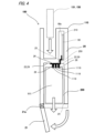
- FIG. 4 is a diagram showing a first example of a manner in which the power supply unit 111 can be attached and detached.
- the case 20 has a bottom wall portion 21 that constitutes at least a part of the lower surface of the case 20.
- the bottom wall portion 21 is provided on the case 20 so as to be openable and closable about a hinge portion 21a extending laterally.
- an opening portion 24 is provided on the lower surface of the case 20, and the opening portion 24 is configured to be openable and closable by the bottom wall portion 21.
- the lower region of the case 20 is formed with a power supply housing 200 capable of housing the power supply unit 111.
- the power supply housing 200 communicates with the outside of the case 20, and it becomes possible to insert the power supply unit 111 into the power supply housing 200 through the opening 24.
- a board accommodating section 210 is formed in the upper region of the case 20. Therefore, in the insertion direction of the power supply unit 111 inserted from the opening 24, the power supply accommodating section 200 and the board accommodating section 210 are provided in this order from the opening 24.
- the board housing section 210 houses the main body side board unit 90, which is configured to include ICs and the like that make up the control section 116.
- the main body side board unit 90 is electrically connected to the power supply section 111 housed in the power supply housing section 200, for example, via a flexible cable 250 or the like. This makes it possible to supply power from the power supply section 111 housed in the power supply housing section 200 to the main body side board unit 90.
- the case 20 is provided with a connection section 26 that is connected to the terminal 1119 of the power supply section 111 housed in the power supply housing section 200.
- the connection section 26 is electrically connected to the main body side board unit 90 via, for example, a flexible cable 250.
- the power supply unit 111 has multiple terminals 1119, and the case 20 has connection parts 26 corresponding to each of the terminals 1119. Also, in the example shown in FIG. 4, all of the terminals 1119 of the power supply unit 111 are provided on the upper surface of the power supply unit 111, and therefore all of the connection parts 26 of the case 20 are also provided on the upper wall part 22 of the power supply accommodating part 200.
- the multiple terminals 1119 provided on the power supply unit 111 can include, for example, a first output terminal 1119a and a second output terminal 1119b, which will be described later.
- the upper wall portion 22 is a partition portion disposed between the power supply accommodating portion 200 and the board accommodating portion 210 in the insertion direction of the power supply unit 111. Because the upper wall portion 22 is disposed between the power supply accommodating portion 200 and the board accommodating portion 210 in the insertion direction of the power supply unit 111, the power supply unit 111 is prevented from entering the board accommodating portion 210 and coming into contact with elements disposed on the main body side board unit 90.
- the upper wall portion 22 functions as a restricting portion 29 that restricts the power supply portion 111 from entering the board accommodation portion 210.
- the restricting portion 29 it is preferable for the restricting portion 29 to cover at least the electrical connection portion between the main body side board unit 90 and the elements arranged on the main body side board unit 90 as viewed from the power supply accommodation portion 200, it is more preferable for the restricting portion 29 to cover the elements arranged on the main body side board unit 90, and it is even more preferable for the restricting portion 29 to cover the entire main body side board unit 90.
- a communication section 25 that communicates between the power supply accommodating section 200 and the board accommodating section 210 is formed in the upper wall section 22, and a flexible cable 250 is inserted into the communication section 25.
- the upper wall section 22 may be provided with a communication section 25 that communicates between the power supply accommodating section 200 and the board accommodating section 210, but the area of the communication section 25 perpendicular to the insertion direction of the power supply section 111 is smaller than the area of the power supply section 111 perpendicular to the insertion direction of the power supply section 111. This prevents the power supply section 111 from entering the board accommodating section 210 through the communication section 25 and coming into contact with elements arranged on the main body side board unit 90.
- the main body side board unit 90 has a first surface 90a on which a plurality of elements and electrical connection parts of the flexible cable 250 are mounted, and the first surface 90a is arranged in a direction perpendicular to the insertion direction of the power supply unit 111. Furthermore, by arranging the board at a position that does not overlap with the position of the communication part 25 when viewed from the insertion direction of the power supply unit 111, the mounting part of the element mounted on the board (i.e., the electrical connection part) is arranged so as not to be exposed to the power supply accommodating part 200.
- the restricting part 29 is arranged between the power supply accommodating part 200 and the mounting part of the element.
- the mounting part of the control element for example, the MCU 1161 described later
- the power supply unit 111 is prevented from coming into contact with the control element that controls the supply of power to the heating part 121, thereby improving safety.
- the power supply housing 200 communicates with the outside of the case 20, making it possible to remove the power supply unit 111 from the power supply housing 200.
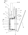
- FIG. 5 is a diagram showing a second example of the attachment/detachment mode of the power supply unit 111. Note that, here, the description will be centered on the parts that are different from the description of Fig. 4, and the description of the parts that are common to the description of Fig. 4 will be omitted or simplified as appropriate.
- the power supply housing 200 communicates with the outside of the case 20, and it becomes possible to insert the power supply unit 111 into the power supply housing 200 from the side of the case 20.
- an opening 24 is provided on the side of the case 20, and the opening 24 is configured to be openable and closable by the panel 30.
- the board accommodating section 210 is not positioned in the insertion direction of the power supply section 111 inserted through the opening 24.
- the terminals 1119 of the power supply unit 111 are provided on each of the top, bottom, and side surfaces of the power supply unit 111. Therefore, the connection parts 26 of the case 20 are also provided on each of the top wall part 22, bottom wall part 21, and side wall part 23. Note that the terminals 1119 of the power supply unit 111 may be concentrated in one location on the power supply unit 111 as shown in FIG. 4, and correspondingly, the connection parts 26 of the case 20 may also be concentrated in one location on the case 20.
- the power supply unit 111 Since the board accommodating section 210 is not positioned in the insertion direction of the power supply unit 111 inserted from the opening 24, the power supply unit 111 does not normally enter the board accommodating section 210. However, if the power supply unit 111 is inserted at an angle from the opening 24, a part of the power supply unit 111 may enter the board accommodating section 210. However, the upper wall section 22, which is arranged between the power supply accommodating section 200 and the board accommodating section 210 as viewed from the power supply accommodating section 200, prevents the power supply unit 111 from coming into contact with the electrical connection section of the element arranged on the main body side board unit 90 with the main body side board unit 90. In this example, the upper wall section 22 functions as a restricting section 29 that restricts the power supply unit 111 from entering the board accommodating section 210.
- the power supply housing 200 communicates with the outside of the case 20, making it possible to remove the power supply unit 111 from the power supply housing 200.
- the panel 30 may be capable of being opened and closed around a hinge portion as described in FIG. 4.
- FIG. 6 is a diagram showing a third example of the manner in which the power supply unit 111 is attached and detached. Note that the following description will focus on the parts that are different from those described in Fig. 4 or 5, and descriptions of the parts that are common to those described in Fig. 4 or 5 will be omitted or simplified as appropriate.
- an opening 24 is provided on the side of the case 20, and the opening 24 is configured to be openable and closable by a panel 30.
- a power supply accommodating section 200 and a board accommodating section 210 are provided in this order from the opening 24.
- a partition section 27 is disposed between the power supply accommodating section 200 and the board accommodating section 210 in the insertion direction of the power supply unit 111.
- the terminals 1119 of the power supply unit 111 are provided on each of the top, bottom, and side surfaces of the power supply unit 111. Therefore, the connection parts 26 of the case 20 are also provided on each of the top wall part 22, bottom wall part 21, and partition part 27. Note that the terminals 1119 of the power supply unit 111 may be concentrated in one place on the power supply unit 111 as shown in FIG. 4, and correspondingly, the connection parts 26 of the case 20 may also be concentrated in one place on the case 20.
- the partition wall 27 may be provided integrally with the case 20, or may be provided separately from the case 20 and attached to the case 20, but is arranged in a fixed state to the case 20 when the power supply unit 111 is replaced. When the power supply unit 111 is replaced, the power supply unit 111 is prevented from entering the board housing portion 210 and coming into contact with elements arranged on the main body side board unit 90.
- the partition wall 27 functions as a restricting portion 29 that restricts the power supply unit 111 from entering the board housing portion 210.
- the partition 27 is penetrated by a flexible cable 250 extending from the connection portion 26 and connected to the main body side board unit 90, and a communication portion 25 is formed to communicate between the power supply accommodating portion 200 and the board accommodating portion 210.
- the partition 27 may be provided with communication portions 25 such as through holes, gaps, notches, etc. other than the through holes through which the flexible cable 250 passes, but the area of the communication portion 25 perpendicular to the insertion direction of the power supply unit 111 is smaller than the area of the power supply unit 111 perpendicular to the insertion direction of the power supply unit 111. This prevents the power supply unit 111 from entering the board accommodating portion 210 through the communication portion 25 and coming into contact with elements arranged on the main body side board unit 90.
- the partition wall 27 preferably covers at least the electrical connection between the elements arranged on the first surface 90a of the main body side board unit 90 as viewed from the opening 24, more preferably covers the elements arranged on the main body side board unit 90, and even more preferably covers the entire main body side board unit 90.
- the power supply housing 200 communicates with the outside of the case 20, making it possible to remove the power supply unit 111 from the power supply housing 200.
- the panel 30 may be capable of being opened and closed around a hinge portion as described in FIG. 4.
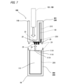
- FIG. 7 is a diagram showing a fourth example of the attachment/detachment mode of the power supply unit 111. Note that, here, the description will focus on the parts that are different from the description of Figs. 4 to 6, and the description of the parts that are common to the description of Figs. 4 to 6 will be omitted or simplified as appropriate.
- the case 20 includes an upper case 201 that constitutes the exterior of the upper region of the suction device 100, and a lower case 202 that constitutes the exterior of the lower region of the suction device 100.
- the power supply unit 10 is attached to the upper case 201 from below.
- both the upper case 201 and the lower case 202 have a generally cylindrical shape extending in the vertical direction, and a screw groove is machined on the outer peripheral surface of one of the lower end of the upper case 201 and the upper end of the lower case 202 and the inner peripheral surface of the other of the lower end of the upper case 201 and the upper end of the lower case 202, and the power supply unit 10 is attached to the upper case 201 by screwing the lower end of the upper case 201 and the upper end of the lower case 202 together.
- a magnet may be provided at one of the lower end of the upper case 201 or the upper end of the lower case 202, and the other of the lower end of the upper case 201 or the upper end of the lower case 202 may be formed from a ferromagnetic material, and the lower end of the upper case 201 and the upper end of the lower case 202 may be attracted to each other by the magnetic force of the magnet, thereby attaching the power supply unit 10 to the upper case 201.
- the lower case 202 may have a claw-shaped or other locking portion, and the locking portion may be locked to the upper case 201, thereby attaching the power supply unit 10 to the upper case 201.
- the power supply section 111 is held in a state in which the terminal 1119 is electrically connected to the connection section 26 of the case 20.
- the power supply unit 111 modularized in the lower case 202 is restricted from entering the board housing portion 210 of the upper case 201.
- the assembly structure of the upper case 201 and the lower case 202 restricts the power supply unit 111 from entering the board housing portion 210 and coming into contact with the elements arranged on the main body side board unit 90, so the assembly structure of the upper case 201 and the lower case 202 serves as a restricting portion 29 that restricts the power supply unit 111 from entering the board housing portion 210.
- the upper wall portion 22 functions as a restricting portion 29 that restricts the power supply unit 111 from entering the board housing portion 210.
- the upper wall 22 may be provided with a communication section 25 between the power supply accommodating section 200 and the board accommodating section 210, but the area of the communication section 25 perpendicular to the insertion direction of the power supply unit 111 is smaller than the area of the power supply unit 111 perpendicular to the insertion direction of the power supply unit 111. This prevents the power supply unit 111 from entering the board accommodating section 210 through the communication section 25 and coming into contact with elements arranged on the main body side board unit 90.
- the power supply unit 111 when the power supply unit 111 is housed in the power supply unit 10, by releasing the screw engagement between the lower end of the upper case 201 and the upper end of the lower case 202, the power supply housing 200 is connected to the outside of the case 20, and the power supply unit 111 can be removed from the power supply housing 200.
- Fig. 8 is a diagram showing an example of the configuration of the power supply unit 111.
- the power line Ln shown in Fig. 8 is a power line to which a reference potential (hereinafter also referred to as "ground potential”) is applied.
- this power line Ln is also referred to as “ground line Ln”, and being electrically connected to the ground line Ln is also referred to as being “grounded”.
- the ground potential is set to 0 [V], and each voltage means a potential difference with respect to the ground potential.
- the power supply unit 111 includes a battery 1111, a fuse 1112, a switch circuit 1113, a protection IC 1114, a battery temperature sensor 1115, and a charging IC 1116.
- the power supply unit 111 has a first output terminal 1119a, a second output terminal 1119b, and a ground terminal 1119c as terminals 1119 (connection terminals) that electrically connect the inside and outside of the power supply unit 111.
- the ground terminal 1119c is grounded.
- the power supply unit 111 is configured by electrically connecting multiple components, such as a battery 1111, a fuse 1112, a switch circuit 1113, a protection IC 1114, a battery temperature sensor 1115, and a charging IC 1116, and packaging them together.
- packing means, for example, assembling multiple components into one package and fixing them so that the relative positions of the components do not change. Packing can be achieved, for example, by covering the multiple components contained within as a single unit with an insulator (insulating material) such as resin.
- multiple components such as the battery 1111 and charging IC 1116 are covered as a single unit by an insulator In and are not exposed to the outside of the power supply unit 111.
- the power supply unit 111 by configuring the power supply unit 111 as a single unit consisting of multiple components such as the battery 1111 and charging IC 1116, it becomes possible to replace these multiple components collectively by replacing the power supply unit 111, improving user convenience.
- Battery 1111 is a secondary battery that has a positive terminal 1111a and a negative terminal 1111b, and is configured to be able to output, for example, a terminal voltage of about 4 V between positive terminal 1111a and negative terminal 1111b.
- the output voltage of battery 1111 i.e., the terminal voltage between positive terminal 1111a and negative terminal 1111b
- Vbat power supply voltage
- various types of secondary batteries such as a lithium ion secondary battery or a nickel-metal hydride battery, can be used as battery 1111.
- the positive terminal 1111a of the battery 1111 is connected to the first output terminal 1119a of the power supply unit 111 and the charging IC 1116 via the fuse 1112.
- the first output terminal 1119a is connected to the positive terminal 1111a of the battery 1111.
- the power supply unit 111 to output power having the power supply voltage Vbat from the first output terminal 1119a, as shown by the arrow ⁇ in FIG. 8.
- the negative terminal 1111b of the battery 1111 is connected to the ground line Ln.
- the fuse 1112 is a protective element that melts when a current equal to or greater than a predetermined value flows.
- a fuse 1112 between the positive terminal 1111a of the battery 1111 and the first output terminal 1119a of the power supply unit 111, even if an overcurrent, which is a current equal to or greater than a predetermined value, is output from the battery 1111, it is possible to prevent the overcurrent from being output to the outside of the power supply unit 111 via the first output terminal 1119a.
- FIG. 8 by connecting the positive terminal 1111a of the battery 1111 to the charging IC 1116 via the fuse 1112, it is also possible to protect the charging IC 1116 from an overcurrent.
- the switch circuit 1113 is a circuit that functions as a switch that turns on and off the charging and discharging of the power supply unit 111 (more specifically, the battery 1111).
- the switch circuit 1113 is configured by connecting a first FET 1113a and a second FET 1113b in series, and is provided on the ground line Ln.
- Each of the first FET 1113a and the second FET 1113b can be, for example, an N-channel MOSFET (Metal-Oxide-Semiconductor Field Effect Transistor).
- MOSFET Metal-Oxide-Semiconductor Field Effect Transistor
- the source terminal of the first FET 1113a is connected to the negative terminal 1111b
- the drain terminal of the first FET 1113a is connected to the drain terminal of the second FET 1113b
- the gate terminal of the first FET 1113a is connected to the protection IC 1114.
- the source terminal of the second FET 1113b is connected to the ground terminal 1119c
- the gate terminal of the second FET 1113b is connected to the protection IC 1114.
- the protection IC 1114 is an IC that functions as a control element (in other words, a controller) that controls the switch circuit 1113. More specifically, the protection IC 1114 is connected to each of the positive terminal 1111a and the negative terminal 1111b of the battery 1111, and is configured to be able to obtain the power supply voltage Vbat, which is the output voltage of the battery 1111. The protection IC 1114 then controls the switch circuit 1113 based on the power supply voltage Vbat.
- the protection IC 1114 can turn the first FET 1113a on (in other words, conductive state) or off (in other words, cut-off state) by controlling the gate voltage of the first FET 1113a. Similarly, the protection IC 1114 can turn the second FET 1113b on or off by controlling the gate voltage of the second FET 1113b.
- the protection IC 1114 stops discharging from the power supply unit 111 by turning off the first FET 1113a. This makes it possible to prevent overdischarge, which occurs when discharging continues even though the power supply voltage Vbat has fallen below the predetermined lower limit.
- the protection IC 1114 may control the switch circuit 1113 based on the current value of the current flowing through the ground line Ln. As an example, if an overcurrent (i.e., a current above a predetermined value) flows through the ground line Ln while the power supply unit 111 is being charged, the protection IC 1114 may stop charging of the power supply unit 111 by turning off the second FET 1113b. In this way, even if an overcurrent occurs while the power supply unit 111 is being charged, it is possible to protect the battery 1111 etc. from the overcurrent.
- an overcurrent i.e., a current above a predetermined value
- the protection IC 1114 may stop discharging from the power supply unit 111 by turning off the first FET 1113a. In this way, even if an overcurrent occurs while discharging from the power supply unit 111, it is possible to protect the main body side board unit 90 and the like from the overcurrent.
- the protection IC 1114 is also connected to, for example, a battery temperature sensor 1115.
- the battery temperature sensor 1115 is a temperature element that can detect the battery temperature Tbat by outputting a parameter (e.g., an electrical resistance value) or a signal related to the temperature of the power supply unit 111 (hereinafter also referred to as "battery temperature Tbat").
- the battery temperature sensor 1115 is an NTC thermistor composed of a resistor having NTC characteristics, or a PTC thermistor composed of a resistor having PTC characteristics, and is placed in close proximity to the battery 1111.
- the protection IC 1114 acquires the battery temperature Tbat based on the output value of the battery temperature sensor 1115.
- the protection IC 1114 can then control the switch circuit 1113 based on the battery temperature Tbat. For example, if a parameter indicating that the battery temperature Tbat is equal to or higher than a predetermined temperature is output from the battery temperature sensor 1115 while the power supply unit 111 is being charged, the protection IC 1114 stops charging the power supply unit 111 by turning off the second FET 1113b. This makes it possible to stop charging if the power supply unit 111 becomes too hot while being charged, thereby improving safety.
- the protection IC 1114 stops discharging from the power supply unit 111 by turning off the first FET 1113a. This makes it possible to stop discharging if the power supply unit 111 becomes too hot during discharging, thereby improving safety.
- the switch circuit 1113 and the protection IC 1114 function as a protection circuit configured to be able to stop charging and discharging the battery 1111.
- the charging IC 1116 is connected to both the charging terminal 1117, which functions as a power receiving unit configured to receive power from an external power source, and the battery 1111, and is an IC that functions as a charging control element that controls the charging of the battery 1111 (i.e., the power supply unit 111) with the power received by the charging terminal 1117.
- the charging IC 1116 is an example of a second control element in this disclosure.
- the charging terminal 1117 can be realized, for example, by a receptacle configured to allow a USB Type-C (registered trademark) plug to be inserted.
- a receptacle configured to allow a USB Type-C plug to be inserted.
- the charging terminal 1117 is not limited to a receptacle compatible with USB Type-C, but may be a receptacle compatible with other standards such as microUSB or Lightning (registered trademark). Also, here, the charging terminal 1117, which is a receptacle, is used as the power receiving unit, but the power receiving unit may also be configured with a power receiving coil or the like that is configured to be able to contactlessly receive power transmitted from an external power source.
- the charging IC 1116 When the charging IC 1116 detects that the power supply unit 111 is connected to an external power source, it charges the power supply unit 111 by supplying the power received from the external power source to the battery 1111, as shown by the arrow ⁇ in FIG. 8. At this time, the power supply unit 111 does not need to be attached to the suction device 100.
- the power supply unit 111 since the power supply unit 111 includes the charging terminal 1117 in addition to the battery 1111, it can be charged independently even when removed from the suction device 100 (more specifically, the case 20). Therefore, if a user has two or more power supply units 111, it is possible to remove one power supply unit 111 from the suction device 100 and charge it, while attaching another power supply unit 111 to the suction device 100 and using it. Therefore, the suction device 100 can be used as usual even while one power supply unit 111 is charging, improving user convenience. Furthermore, if the power supply unit 111 is configured to include the charging IC 1116, it can be appropriately charged independently even when removed from the suction device 100.
- the charging terminal 1117 is configured to be connectable to an external power source from the outside when the power supply unit 111 is housed in the power supply housing 200.
- the case 20 is configured to have an opening at a location corresponding to the charging terminal 1117 of the power supply unit 111 housed in the power supply housing 200, and a plug can be inserted into the charging terminal 1117 through this opening. In this manner, the power supply unit 111 can be charged without removing it from the case 20. This improves convenience for users who wish to charge the power supply unit 111 while it is attached to the suction device 100.
- the charging IC 1116 controls the current value of the charging current (hereinafter also simply referred to as "charging current") supplied to the battery 1111 during charging.
- the charging IC 1116 changes the charging current in response to the power supply voltage Vbat, and for example, it is preferable to reduce (i.e., narrow) the charging current as the power supply voltage Vbat increases.
- the charging IC 1116 changes the charging current in response to the battery temperature Tbat, and for example, it is preferable to reduce the charging current as the battery temperature Tbat increases.
- the charging IC 1116 is connected to the second output terminal 1119b in addition to the battery 1111.
- the second output terminal 1119b is connected to the positive terminal 1111a of the battery 1111 via the charging IC 1116.
- the charging IC 1116 is configured to be able to output from the second output terminal 1119b. More specifically, as shown by the arrow ⁇ in FIG. 8, the charging IC 1116 outputs the power input from the battery 1111 (in other words, the power of the power supply voltage Vbat) as the first system voltage Vsys1 from the second output terminal 1119b.
- the charging IC 1116 may output the voltage input from the battery 1111 directly from the second output terminal 1119b, or may step up or step down the voltage within the charging IC 1116 before outputting it.
- the first system voltage Vsys1 is a voltage greater than 0.
- the first system voltage Vsys1 may be a voltage different from the power supply voltage Vbat, or may be the same voltage.
- the first output terminal 1119a of the power supply unit 111 is connected to, for example, the first connection portion 26a of the connection portions 26 provided in the case 20, which is connected to the first power system 91 that supplies power to the heating portion 121.
- the first power system 91 includes a first DC/DC converter 91a mounted on a board that constitutes the main body side board unit 90, and the first connection section 26a is connected to the first DC/DC converter 91a.
- the first DC/DC converter 91a is supplied with power output from the first output terminal 1119a (i.e., power of the power supply voltage Vbat).
- the first DC/DC converter 91a then generates, from the supplied power, power of the heater voltage Vheat suitable for heating by the heating section 121.
- the heater voltage Vheat generated by the first DC/DC converter 91a is supplied to the heating unit 121 (e.g., a heating resistor constituting the heating unit 121), thereby heating by the heating unit 121.
- the heater voltage Vheat is, for example, a voltage higher than the power supply voltage Vbat, and can be set to 5 V as an example. This allows the heating unit 121 to perform heating efficiently.
- the first power system 91 may further include various elements such as a switch (e.g., a FET). As an example, it may include a switch that turns on and off the power supply from the first DC/DC converter 91a to the heating unit 121.
- the MCU 1161 is an IC mainly composed of a processor that performs various calculations, and is a control element that controls the entire suction device 100 by the processor executing a program prepared in advance.
- the MCU 1161 is an example of a first control element that controls the supply of power to the heating unit 121.
- the suction device 100 by providing the first connection part 26a connected to the first output terminal 1119a and the second connection part 26b connected to the second output terminal 1119b, it is possible to separately receive the power output from the first output terminal 1119a (in other words, the power of the battery 1111) and the power output from the second output terminal 1119b (in other words, the power controlled by the charging IC 1116). Therefore, in the suction device 100, it is possible to utilize the power output from the first output terminal 1119a and the power output from the second output terminal 1119b for different purposes.
- the MCU 1161 may instruct the charging IC 1116 to start charging the battery 1111 when the power supply unit 111 housed in the power supply housing 200 is electrically connected to an external power source and power is not being supplied from the power supply unit 111 to the heating unit 121, but may not instruct the charging IC 1116 to start charging the battery 1111 when the power supply unit 111 housed in the power supply housing 200 is electrically connected to an external power source and power is being supplied from the power supply unit 111 to the heating unit 121. Then, the charging IC 1116 may start charging the battery 1111 in response to receiving an instruction from the MCU 1161 to start charging the battery 1111.
- charging of the battery 1111 can be prevented from being started when power is being supplied from the power supply unit 111 to the heating unit 121, and it is possible to prevent the power supply unit 111 from being in a high-load state due to both power supply and charging to the heating unit 121 being performed at the same time.
- the charging IC 1116 may be configured to detect the output from the first output terminal 1119a (in other words, the output of power at the power supply voltage Vbat), and not charge the battery 1111 if there is an output from the first output terminal 1119a. Even in this way, charging of the battery 1111 can be prevented when there is an output from the first output terminal 1119a (in other words, the output of power at the power supply voltage Vbat), and it is possible to prevent both the supply of power to the heating unit 121 and charging from occurring at the same time, which would cause the power supply unit 111 to enter a high load state.
- the first output terminal 1119a in other words, the output of power at the power supply voltage Vbat
- the MCU 1161 may also control the charging IC 1116 so that the battery 1111 is charged or not charged depending on the state of the battery 1111 when the power supply unit 111 housed in the power supply housing 200 is electrically connected to an external power source. As an example, when the power supply unit 111 housed in the power supply housing 200 is electrically connected to an external power source, the MCU 1161 may control the charging IC 1116 so that the battery 1111 is not charged if the battery 1111 is in a predetermined state such as over-discharge or deep discharge, and the battery 1111 is charged if the battery is in another state.
- the charging IC 1116 may independently control the charging of the battery 1111, while when the power supply unit 111 is attached to the power supply unit 110, the charging IC 1116 may control the charging of the battery 1111 according to an instruction from the MCU 1161.
- the MCU 1161 can determine whether the battery 1111 is in a specified state, for example, based on the power supply voltage Vbat received by the main body side board unit 90 from the power supply unit 111. Also, a remaining capacity meter IC that obtains the remaining capacity of the battery 1111 from the power supply voltage Vbat or the like may be provided in the main body side board unit 90, and the MCU 1161 can determine whether the battery 1111 is in a specified state based on input from this remaining capacity meter IC (for example, the measured value of the power supply voltage Vbat or the like itself, or an error signal that may be output from the remaining capacity meter IC based on the measured value).
- this remaining capacity meter IC for example, the measured value of the power supply voltage Vbat or the like itself, or an error signal that may be output from the remaining capacity meter IC based on the measured value.
- the power supply unit 111 is further divided into a first output terminal 1119a through which the power of the battery 1111 (in other words, the power of the power supply voltage Vbat) is output, and a second output terminal 1119b through which the power of the charging IC 1116 (in other words, the power of the first system voltage Vsys1) is output. For this reason, it is not necessary to assume that a large amount of power such as the power of the power supply voltage Vbat will flow through the charging IC 1116 and/or the power line from the charging IC 1116 to the second output terminal 1119b. By directly connecting the first output terminal 1119a to the battery 1111, a large amount of power such as the power of the power supply voltage Vbat can be output directly from the first output terminal 1119a.
- this embodiment can provide a suction device 100 that improves user convenience.
- the power supply unit 111 is provided with a first output terminal 1119a that outputs the power of the battery 1111 (in other words, the power of the power supply voltage Vbat), and a second output terminal 1119b that outputs the power of the charging IC 1116 (in other words, the power of the first system voltage Vsys1), but this is not limited to this.
- the first output terminal 1119a and the second output terminal 1119b only the first output terminal 1119a may be provided, and the power of the power supply voltage Vbat and the power of the first system voltage Vsys1 may be separated within the main body side board unit 90 and each may flow through a separate power line.
- FIG. 9 is a diagram showing another example of the configuration of the power supply unit 111. Note that the following description will focus on the parts that are different from the description in FIG. 8, and the description of the parts that are common to the description in FIG. 8 will be omitted or simplified as appropriate. Please note that the main body side board unit 90 and the like are not shown in FIG. 9.
- the charging IC 1116 may be provided in the charger 900, for example.
- the charger 900 includes, in addition to the charging IC 1116, an input terminal (not shown) connected to an external power source (for example, a commercial power source), and an output terminal 901 and a ground terminal 902 connected to a charging terminal 1117 of the power supply unit 111.
- an external power source for example, a commercial power source
- an output terminal 901 and a ground terminal 902 connected to a charging terminal 1117 of the power supply unit 111.
- power from an external power source is input to the charging IC 1116 via the input terminal of the charger 900.
- the charging IC 1116 generates, for example, power (for example, DC power having a predetermined voltage) that the power supply unit 111 can accept in terms of hardware from the input power, and outputs the power to the charging terminal 1117 of the power supply unit 111 via the output terminal 901.
- the power output from the charger 900 in this manner is supplied to the battery 1111 of the power supply unit 111, and the battery 1111 is charged.
- An aerosol generating device (inhalation device 100, 100A, 100B) that generates an aerosol by heating an aerosol source (cartridge 120, flavor source 131, stick-shaped substrate 150),
- a power supply unit (power supply unit 111, 111A, 111B) configured to be capable of supplying power to a heating unit (heating unit 121, 121A, 121B) that heats the aerosol source and to be chargeable by power received from an external power source;
- a substrate main body side substrate unit 90) on which a plurality of electronic components including a first control element (MCU 1161) that controls the supply of power to the heating unit are mounted;
- a case (case 20) having a power supply accommodating section (power supply accommodating section 200) that accommodates the power supply unit, connection sections (first connection section 26a, second connection section 26b) that electrically connect the power supply unit accommodated in the power supply accommodating section and the electronic component, and a board accommodating section (board accommodating section 210) that accommodates the board; Equipped with The power supply
- the power supply unit since the power supply unit includes a power receiving unit in addition to a battery, it can be charged independently even when removed from the case of the aerosol generating device. Therefore, if a user has two or more power supply units, it is possible to remove one power supply unit from the aerosol generating device and charge it, while attaching another power supply unit to the aerosol generating device and using it. Therefore, the aerosol generating device can be used as usual even while one power supply unit is charging, improving user convenience.
- the aerosol generating device according to (1), The aerosol generating device, wherein the power supply unit further includes a second control element (charging IC 1116) that controls charging of the battery using the power received by the power receiving unit.
- a second control element charging IC 1116
- the power supply unit since the power supply unit is equipped with the second control element, it can be properly charged independently even when removed from the case of the aerosol generating device.
- connection terminal is A first output terminal (first output terminal 1119a) connected to the battery; a second output terminal (second output terminal 1119b) connected to the battery via the second control element; Including, The second control element is further configured to be able to control an output from the second output terminal. Aerosol generating device.
- the battery power can be output directly from the first output terminal, and the power controlled by the second control element can be output from the second output terminal. This makes it possible to supply the battery power and the power controlled by the second control element separately to the aerosol generating device.
- connection portion is a first connection portion (first connection portion 26a) connected to the first output terminal of the power supply portion accommodated in the power supply accommodation portion; a second connection portion (second connection portion 26b) connected to the second output terminal of the power supply portion accommodated in the power supply accommodation portion; Including, Aerosol generating device.
- the aerosol generating device can separately receive the power output from the first output terminal (in other words, the battery power) and the power output from the second output terminal (in other words, the power controlled by the second control element).
- the aerosol generating device is connected to a first power system (first power system 91) that supplies power to the heating portion,
- the second connection portion is connected to a second power system (second power system 92) that supplies power to the first control element. Aerosol generating device.
- the first power system that supplies power to the heating section can be supplied with the battery's power as is, and the second power system that supplies power to the first control element can be supplied with power controlled by the second control element.
- the aerosol generating device includes: A temperature element (battery temperature sensor 1115) that outputs a parameter or signal related to the temperature of the power supply unit; A protection circuit (a switch circuit 1113, a protection IC 1114) configured to be able to stop charging the battery; Further equipped with the protection circuit stops charging the battery when the parameter or the signal indicating that the temperature of the power supply unit is equal to or higher than a predetermined temperature is output from the temperature element during charging of the battery; Aerosol generating device.
- a temperature element battery temperature sensor 1115
- a protection circuit a switch circuit 1113, a protection IC 1114
- the power supply unit can be prevented from becoming too hot, and deterioration of the battery can be prevented.
- the protection circuit further stops charging of the battery when the terminal voltage of the battery reaches a predetermined upper limit during charging of the battery. Aerosol generating device.
- the protection circuit further comprises: A discharge from the battery can be stopped, when the parameter or the signal indicating that the temperature of the power supply unit is equal to or higher than a predetermined temperature is output from the temperature element during discharging from the battery, discharging from the battery is stopped. Aerosol generating device.
- the power supply unit can be prevented from becoming too hot while discharging, thereby preventing battery deterioration.
- the aerosol generating device (9) The aerosol generating device according to (8), The protection circuit further stops discharging the battery when the terminal voltage of the battery reaches a predetermined lower limit during discharging of the battery. Aerosol generating device.
- the user can start charging the battery when the power supply unit is connected to an external power source, which improves user convenience compared to a case where other operations are required to charge the battery in addition to connecting the power supply unit to an external power source.
- the aerosol generating device (11)
- the second control element is When the power supply unit is electrically connected to the external power source and power is not being supplied from the power supply unit to the heating unit, charging of the battery is started; When the power supply unit is electrically connected to the external power source and power is being supplied from the power supply unit to the heating unit, charging of the battery is not started. Aerosol generating device.
- the aerosol generating device according to any one of (2) to (5),
- the first control element is instructing the second control element to start charging the battery when the power supply unit accommodated in the power supply accommodating section is electrically connected to the external power source and power is not being supplied from the power supply unit to the heating unit;
- the second control element starts charging the battery in response to receiving an instruction to start charging the battery from the first control element. Aerosol generating device.
- the aerosol generating device according to any one of (3) to (5), The second control element detects an output from the first output terminal, When there is an output from the first output terminal, charging of the battery is not performed. Aerosol generating device.
- the aerosol generating device according to any one of (1) to (13),
- the power receiving unit is configured to be connectable to the external power source from outside in a state in which the power source unit is accommodated in the power source accommodating unit. Aerosol generating device.
- the power supply unit can be charged without removing it from the case of the aerosol generating device. This improves convenience for users who wish to charge the aerosol generating device while keeping the power supply unit attached.
- the aerosol generating device according to any one of (1) to (14),
- the power receiving unit is a receptacle configured to allow insertion of a plug that supplies power from the external power source. Aerosol generating device.
- Case 26a First connection portion (connection portion) 26b Second connection portion (connection portion) 90 Main body side board unit (board) 100, 100A, 100B Suction device (aerosol generating device) 111, 111A, 111B Power supply unit 121, 121A, 121B Heating unit 200 Power supply housing unit 210 Substrate housing unit 1111 Battery 1113 Switch circuit (protection circuit) 1114 Protection IC (protection circuit) 1115 Battery temperature sensor (temperature element) 1116 Charging IC (second control element) 1119a First output terminal (connection terminal) 1119b Second output terminal (connection terminal) 1161 MCU (first control element)
Landscapes
- Engineering & Computer Science (AREA)
- Power Engineering (AREA)
- Manufacturing & Machinery (AREA)
- Chemical & Material Sciences (AREA)
- Chemical Kinetics & Catalysis (AREA)
- Electrochemistry (AREA)
- General Chemical & Material Sciences (AREA)
- Charge And Discharge Circuits For Batteries Or The Like (AREA)
- Catching Or Destruction (AREA)
Abstract
Description
エアロゾル源を加熱することによりエアロゾルを生成するエアロゾル生成装置であって、
前記エアロゾル源を加熱する加熱部へ電力を供給可能、且つ外部電源から受け付けた電力により充電可能に構成された電源部と、
前記加熱部への電力の供給を制御する第1制御素子を含む複数の電子部品が実装された基板と、
前記電源部を収容する電源収容部、前記電源収容部に収容された前記電源部と前記電子部品とを電気的に接続する接続部、及び前記基板を収容する基板収容部を有するケースと、
を備え、
前記電源部は、
電池と、前記外部電源から電力を受付可能に構成された受電部と、前記接続部と電気的に接続可能な接続端子とがひとまとまりに固定されて構成され、且つ、ひとまとまりに固定された状態で前記電源収容部に着脱可能に配置される、
エアロゾル生成装置である。
本開示のエアロゾル生成装置の一例である吸引装置は、ユーザにより吸引される物質を生成する装置である。以下では、吸引装置により生成される物質が、エアロゾルであるものとして説明する。他に、吸引装置により生成される物質は、気体であってもよい。
図1は、吸引装置の第1構成例を模式的に示す模式図である。図1に示すように、本構成例の吸引装置100Aは、電源ユニット110A、カートリッジ120、及び香味付与カートリッジ130を含んで構成される。電源ユニット110Aは、電源部111A、センサ部112A、通知部113A、記憶部114A、通信部115A、及び制御部116Aを含んで構成される。カートリッジ120は、加熱部121A、液誘導部122、及び液貯蔵部123を含んで構成される。香味付与カートリッジ130は、香味源131、及びマウスピース124を含んで構成される。カートリッジ120及び香味付与カートリッジ130には、空気流路180が形成される。
図2は、吸引装置の第2構成例を模式的に示す模式図である。図2に示すように、本構成例の吸引装置100Bは、電源部111B、センサ部112B、通知部113B、記憶部114B、通信部115B、制御部116B、加熱部121B、収容部140、及び断熱部144を含む。
図3は、吸引装置100の外観構成の一例を示す図である。図3に示すように、吸引装置100は、例えば、ケース20と、シャッタ50とを備える。ケース20は、例えば、吸引装置100に取り付けられた電源部111や本体側基板ユニット90(例えば図4~図7を参照)等を収容する。
前述したように、電源部111は、吸引装置100のケース20に対して着脱可能に設けられている。以下、電源部111の着脱態様の例について、具体的に説明する。なお、以下では、吸引装置100において、吸引装置100に対する香味源131又はスティック型基材150の挿抜方向を上下方向とし、吸引装置100において香味源131又はスティック型基材150が挿入される側を上方と定義して説明する。すなわち、吸引装置100には、上方から香味源131又はスティック型基材150が挿入される。また、上下方向と直交する方向を横方向という場合があり、横方向を向く面を側面という場合がある。
図4は、電源部111の着脱態様の第1例を示す図である。図4に示すように、ケース20は、ケース20の下面の少なくとも一部を構成する底壁部21を有する。底壁部21は、横方向に延びるヒンジ部21aを軸に開閉可能にケース20に設けられる。言い換えると、ケース20の下面には開口部24が設けられ、開口部24が底壁部21によって開閉可能に構成される。
図5は、電源部111の着脱態様の第2例を示す図である。なお、ここでは、図4の説明と異なる部分を中心に説明することとし、図4の説明と共通する部分の説明は適宜省略又は簡略化する。
図6は、電源部111の着脱態様の第3例を示す図である。なお、ここでは、図4又は図5の説明と異なる部分を中心に説明することとし、図4又は図5の説明と共通する部分の説明は適宜省略又は簡略化する。
図7は、電源部111の着脱態様の第4例を示す図である。なお、ここでは、図4~6の説明と異なる部分を中心に説明することとし、図4~6の説明と共通する部分の説明は適宜省略又は簡略化する。
図8は、電源部111の一構成例を示す図である。図8に示す電力線Lnは、基準電位(以下、「グラウンド電位」とも称する)が印加される電力線である。以下、この電力線Lnを「グラウンドラインLn」とも称し、グラウンドラインLnと電気的に接続されることを「グラウンドされる」とも称する。また、以下では、特段の断りがない限り、グラウンド電位を0[V]とし、各電圧はグラウンド電位との電位差を意味するものとする。
前記エアロゾル源を加熱する加熱部(加熱部121、121A、121B)へ電力を供給可能、且つ外部電源から受け付けた電力により充電可能に構成された電源部(電源部111、111A、111B)と、
前記加熱部への電力の供給を制御する第1制御素子(MCU1161)を含む複数の電子部品が実装された基板(本体側基板ユニット90)と、
前記電源部を収容する電源収容部(電源収容部200)、前記電源収容部に収容された前記電源部と前記電子部品とを電気的に接続する接続部(第1接続部26a、第2接続部26b)、及び前記基板を収容する基板収容部(基板収容部210)を有するケース(ケース20)と、
を備え、
前記電源部は、
電池と、前記外部電源から電力を受付可能に構成された受電部(充電端子1117)と、前記接続部と電気的に接続可能な接続端子(第1出力端子1119a、第2出力端子1119b)とがひとまとまりに固定されて構成され、且つ、ひとまとまりに固定された状態で前記電源収容部に着脱可能に配置される、
エアロゾル生成装置。
前記電源部は、前記受電部によって受け付けた電力による前記電池の充電を制御する第2制御素子(充電IC1116)をさらに備える、エアロゾル生成装置。
前記接続端子は、
前記電池へ接続される第1出力端子(第1出力端子1119a)と、
前記第2制御素子を介して前記電池へ接続される第2出力端子(第2出力端子1119b)と、
を含み、
前記第2制御素子は、さらに、前記第2出力端子からの出力を制御可能に構成される、
エアロゾル生成装置。
前記接続部は、
前記電源収容部に収容された前記電源部の前記第1出力端子と接続される第1接続部(第1接続部26a)と、
前記電源収容部に収容された前記電源部の前記第2出力端子と接続される第2接続部(第2接続部26b)と、
を含む、
エアロゾル生成装置。
前記第1接続部は、前記加熱部へ電力を供給する第1電力系統(第1電力系統91)へ接続され、
前記第2接続部は、前記第1制御素子へ電力を供給する第2電力系統(第2電力系統92)へ接続される、
エアロゾル生成装置。
前記電源部は、
前記電源部の温度に関するパラメータ又は信号を出力する温度素子(電池温度センサ1115)と、
前記電池の充電を停止可能に構成された保護回路(スイッチ回路1113、保護IC1114)と、
をさらに備え、
前記保護回路は、前記電池の充電中に前記電源部の温度が所定温度以上であることを示す前記パラメータ又は前記信号が前記温度素子から出力された場合に、前記電池の充電を停止させる、
エアロゾル生成装置。
前記保護回路は、さらに、前記電池の充電中に前記電池の端子電圧が所定の上限値に達した場合に、前記電池の充電を停止させる、
エアロゾル生成装置。
前記保護回路は、さらに、
前記電池からの放電を停止可能に構成され、
前記電池からの放電中に前記電源部の温度が所定温度以上であることを示す前記パラメータ又は前記信号が前記温度素子から出力された場合に、前記電池からの放電を停止させる、
エアロゾル生成装置。
前記保護回路は、さらに、前記電池の放電中に前記電池の端子電圧が所定の下限値に達した場合に、前記電池の放電を停止させる、
エアロゾル生成装置。
前記第2制御素子は、前記電源部が前記外部電源と電気的に接続されたことに応じて、前記電池の充電を開始する、
エアロゾル生成装置。
前記第2制御素子は、
前記電源部が前記外部電源と電気的に接続されたときに前記電源部から前記加熱部への電力供給が行われていない場合には、前記電池の充電を開始し、
前記電源部が前記外部電源と電気的に接続されたときに前記電源部から前記加熱部への電力供給が行われている場合には、前記電池の充電を開始しない、
エアロゾル生成装置。
前記第1制御素子は、
前記電源収容部に収容された前記電源部が前記外部電源と電気的に接続されたときに前記電源部から前記加熱部への電力供給が行われていない場合には、前記電池の充電を開始するように前記第2制御素子に対して指示し、
前記電源収容部に収容された前記電源部が前記外部電源と電気的に接続されたときに前記電源部から前記加熱部への電力供給が行われている場合には、前記電池の充電を開始する旨を指示せず、
前記第2制御素子は、前記電池の充電を開始する旨の指示を前記第1制御素子から受け付けたことに応じて、前記電池の充電を開始する、
エアロゾル生成装置。
前記第2制御素子は、前記第1出力端子からの出力を検知し、
前記第1出力端子からの出力が有る場合には前記電池の充電を行わない、
エアロゾル生成装置。
前記受電部は、前記電源部が前記電源収容部に収容された状態で外部から前記外部電源と接続可能に構成される、
エアロゾル生成装置。
前記受電部は、前記外部電源の電力を供給するプラグを挿入可能に構成されたレセプタクルである、
エアロゾル生成装置。
26a 第1接続部(接続部)
26b 第2接続部(接続部)
90 本体側基板ユニット(基板)
100、100A、100B 吸引装置(エアロゾル生成装置)
111、111A、111B 電源部
121、121A、121B 加熱部
200 電源収容部
210 基板収容部
1111 電池
1113 スイッチ回路(保護回路)
1114 保護IC(保護回路)
1115 電池温度センサ(温度素子)
1116 充電IC(第2制御素子)
1119a 第1出力端子(接続端子)
1119b 第2出力端子(接続端子)
1161 MCU(第1制御素子)
Claims (15)
- エアロゾル源を加熱することによりエアロゾルを生成するエアロゾル生成装置であって、
前記エアロゾル源を加熱する加熱部へ電力を供給可能、且つ外部電源から受け付けた電力により充電可能に構成された電源部と、
前記加熱部への電力の供給を制御する第1制御素子を含む複数の電子部品が実装された基板と、
前記電源部を収容する電源収容部、前記電源収容部に収容された前記電源部と前記電子部品とを電気的に接続する接続部、及び前記基板を収容する基板収容部を有するケースと、
を備え、
前記電源部は、
電池と、前記外部電源から電力を受付可能に構成された受電部と、前記接続部と電気的に接続可能な接続端子とがひとまとまりに固定されて構成され、且つ、ひとまとまりに固定された状態で前記電源収容部に着脱可能に配置される、
エアロゾル生成装置。 - 請求項1に記載のエアロゾル生成装置であって、
前記電源部は、前記受電部によって受け付けた電力による前記電池の充電を制御する第2制御素子をさらに備える、エアロゾル生成装置。 - 請求項2に記載のエアロゾル生成装置であって、
前記接続端子は、
前記電池へ接続される第1出力端子と、
前記第2制御素子を介して前記電池へ接続される第2出力端子と、
を含み、
前記第2制御素子は、さらに、前記第2出力端子からの出力を制御可能に構成される、
エアロゾル生成装置。 - 請求項3に記載のエアロゾル生成装置であって、
前記接続部は、
前記電源収容部に収容された前記電源部の前記第1出力端子と接続される第1接続部と、
前記電源収容部に収容された前記電源部の前記第2出力端子と接続される第2接続部と、
を含む、
エアロゾル生成装置。 - 請求項4に記載のエアロゾル生成装置であって、
前記第1接続部は、前記加熱部へ電力を供給する第1電力系統へ接続され、
前記第2接続部は、前記第1制御素子へ電力を供給する第2電力系統へ接続される、
エアロゾル生成装置。 - 請求項1から5のいずれか1項に記載のエアロゾル生成装置であって、
前記電源部は、
前記電源部の温度に関するパラメータ又は信号を出力する温度素子と、
前記電池の充電を停止可能に構成された保護回路と、
をさらに備え、
前記保護回路は、前記電池の充電中に前記電源部の温度が所定温度以上であることを示す前記パラメータ又は前記信号が前記温度素子から出力された場合に、前記電池の充電を停止させる、
エアロゾル生成装置。 - 請求項6に記載のエアロゾル生成装置であって、
前記保護回路は、さらに、前記電池の充電中に前記電池の端子電圧が所定の上限値に達した場合に、前記電池の充電を停止させる、
エアロゾル生成装置。 - 請求項6又は7に記載のエアロゾル生成装置であって、
前記保護回路は、さらに、
前記電池からの放電を停止可能に構成され、
前記電池からの放電中に前記電源部の温度が所定温度以上であることを示す前記パラメータ又は前記信号が前記温度素子から出力された場合に、前記電池からの放電を停止させる、
エアロゾル生成装置。 - 請求項8に記載のエアロゾル生成装置であって、
前記保護回路は、さらに、前記電池の放電中に前記電池の端子電圧が所定の下限値に達した場合に、前記電池の放電を停止させる、
エアロゾル生成装置。 - 請求項2から5のいずれか1項に記載のエアロゾル生成装置であって、
前記第2制御素子は、前記電源部が前記外部電源と電気的に接続されたことに応じて、前記電池の充電を開始する、
エアロゾル生成装置。 - 請求項10に記載のエアロゾル生成装置であって、
前記第2制御素子は、
前記電源部が前記外部電源と電気的に接続されたときに前記電源部から前記加熱部への電力供給が行われていない場合には、前記電池の充電を開始し、
前記電源部が前記外部電源と電気的に接続されたときに前記電源部から前記加熱部への電力供給が行われている場合には、前記電池の充電を開始しない、
エアロゾル生成装置。 - 請求項2から5のいずれか1項に記載のエアロゾル生成装置であって、
前記第1制御素子は、
前記電源収容部に収容された前記電源部が前記外部電源と電気的に接続されたときに前記電源部から前記加熱部への電力供給が行われていない場合には、前記電池の充電を開始するように前記第2制御素子に対して指示し、
前記電源収容部に収容された前記電源部が前記外部電源と電気的に接続されたときに前記電源部から前記加熱部への電力供給が行われている場合には、前記電池の充電を開始する旨を指示せず、
前記第2制御素子は、前記電池の充電を開始する旨の指示を前記第1制御素子から受け付けたことに応じて、前記電池の充電を開始する、
エアロゾル生成装置。 - 請求項3から5のいずれか1項に記載のエアロゾル生成装置であって、
前記第2制御素子は、前記第1出力端子からの出力を検知し、
前記第1出力端子からの出力が有る場合には前記電池の充電を行わない、
エアロゾル生成装置。 - 請求項1から13のいずれか1項に記載のエアロゾル生成装置であって、
前記受電部は、前記電源部が前記電源収容部に収容された状態で外部から前記外部電源と接続可能に構成される、
エアロゾル生成装置。 - 請求項1から14のいずれか1項に記載のエアロゾル生成装置であって、
前記受電部は、前記外部電源の電力を供給するプラグを挿入可能に構成されたレセプタクルである、
エアロゾル生成装置。
Priority Applications (4)
| Application Number | Priority Date | Filing Date | Title |
|---|---|---|---|
| PCT/JP2023/044710 WO2025126397A1 (ja) | 2023-12-13 | 2023-12-13 | エアロゾル生成装置 |
| CN202380104619.4A CN122373911A (zh) | 2023-12-13 | 2023-12-13 | 气溶胶产生装置 |
| KR1020267017791A KR20260090733A (ko) | 2023-12-13 | 2023-12-13 | 에어로졸 생성 장치 |
| JP2025563153A JPWO2025126397A1 (ja) | 2023-12-13 | 2023-12-13 |
Applications Claiming Priority (1)
| Application Number | Priority Date | Filing Date | Title |
|---|---|---|---|
| PCT/JP2023/044710 WO2025126397A1 (ja) | 2023-12-13 | 2023-12-13 | エアロゾル生成装置 |
Publications (1)
| Publication Number | Publication Date |
|---|---|
| WO2025126397A1 true WO2025126397A1 (ja) | 2025-06-19 |
Family
ID=96056851
Family Applications (1)
| Application Number | Title | Priority Date | Filing Date |
|---|---|---|---|
| PCT/JP2023/044710 Pending WO2025126397A1 (ja) | 2023-12-13 | 2023-12-13 | エアロゾル生成装置 |
Country Status (4)
| Country | Link |
|---|---|
| JP (1) | JPWO2025126397A1 (ja) |
| KR (1) | KR20260090733A (ja) |
| CN (1) | CN122373911A (ja) |
| WO (1) | WO2025126397A1 (ja) |
Citations (7)
| Publication number | Priority date | Publication date | Assignee | Title |
|---|---|---|---|---|
| JP2001045672A (ja) * | 1999-07-30 | 2001-02-16 | Sanyo Electric Co Ltd | 複数の二次電池の放電方法と組電池 |
| WO2015155811A1 (ja) * | 2014-04-10 | 2015-10-15 | 三洋電機株式会社 | 電源装置とこの電源装置に接続される電子機器への給電方法 |
| CN107373765A (zh) | 2017-08-15 | 2017-11-24 | 深圳葆威道科技有限公司 | 一种新型的烤烟电子烟 |
| JP2021083384A (ja) * | 2019-11-28 | 2021-06-03 | 日本たばこ産業株式会社 | 香味源容器及び非燃焼式吸引器 |
| JP2022524791A (ja) | 2019-03-11 | 2022-05-10 | ニコベンチャーズ トレーディング リミテッド | エアロゾル供給デバイス |
| CN217218154U (zh) * | 2022-01-24 | 2022-08-19 | 深圳市吉迩技术有限公司 | 一种主机及气溶胶发生装置 |
| WO2023281715A1 (ja) * | 2021-07-08 | 2023-01-12 | 日本たばこ産業株式会社 | エアロゾル生成装置の電源ユニット |
-
2023
- 2023-12-13 KR KR1020267017791A patent/KR20260090733A/ko active Pending
- 2023-12-13 CN CN202380104619.4A patent/CN122373911A/zh active Pending
- 2023-12-13 WO PCT/JP2023/044710 patent/WO2025126397A1/ja active Pending
- 2023-12-13 JP JP2025563153A patent/JPWO2025126397A1/ja active Pending
Patent Citations (7)
| Publication number | Priority date | Publication date | Assignee | Title |
|---|---|---|---|---|
| JP2001045672A (ja) * | 1999-07-30 | 2001-02-16 | Sanyo Electric Co Ltd | 複数の二次電池の放電方法と組電池 |
| WO2015155811A1 (ja) * | 2014-04-10 | 2015-10-15 | 三洋電機株式会社 | 電源装置とこの電源装置に接続される電子機器への給電方法 |
| CN107373765A (zh) | 2017-08-15 | 2017-11-24 | 深圳葆威道科技有限公司 | 一种新型的烤烟电子烟 |
| JP2022524791A (ja) | 2019-03-11 | 2022-05-10 | ニコベンチャーズ トレーディング リミテッド | エアロゾル供給デバイス |
| JP2021083384A (ja) * | 2019-11-28 | 2021-06-03 | 日本たばこ産業株式会社 | 香味源容器及び非燃焼式吸引器 |
| WO2023281715A1 (ja) * | 2021-07-08 | 2023-01-12 | 日本たばこ産業株式会社 | エアロゾル生成装置の電源ユニット |
| CN217218154U (zh) * | 2022-01-24 | 2022-08-19 | 深圳市吉迩技术有限公司 | 一种主机及气溶胶发生装置 |
Also Published As
| Publication number | Publication date |
|---|---|
| CN122373911A (zh) | 2026-07-10 |
| JPWO2025126397A1 (ja) | 2025-06-19 |
| KR20260090733A (ko) | 2026-06-16 |
Similar Documents
| Publication | Publication Date | Title |
|---|---|---|
| JP7560403B2 (ja) | エアロゾル吸引器の電源ユニット | |
| JP7621163B2 (ja) | エアロゾル生成装置 | |
| JP7571235B2 (ja) | エアロゾル生成装置 | |
| US12127603B2 (en) | Charging solutions for aerosol generation device | |
| KR102227135B1 (ko) | 전기가열식 에어로졸 발생기용 카토마이저 | |
| JP7543218B2 (ja) | エアロゾル生成装置 | |
| US20220022533A1 (en) | Case for Aerosol Generation Device | |
| EP4368039A1 (en) | Power supply unit for aerosol generation device | |
| JP7610952B2 (ja) | 吸引装置の制御ユニット及び吸引装置の制御方法 | |
| JP7611408B2 (ja) | エアロゾル生成装置の電源ユニット | |
| JP7681115B2 (ja) | エアロゾル生成装置の電源ユニット | |
| JP7578721B2 (ja) | 吸引装置、制御方法、及びプログラム | |
| EP4635331A1 (en) | Power supply unit for aerosol-generating device, and aerosol-generating device | |
| KR20250122505A (ko) | 에어로졸 생성 시스템 | |
| JP7764592B2 (ja) | エアロゾル生成装置 | |
| WO2025126399A1 (ja) | エアロゾル生成装置 | |
| WO2025126396A1 (ja) | エアロゾル生成装置 | |
| EP4691299A1 (en) | Power source unit for aerosol generation device, and aerosol generation device | |
| WO2024171268A1 (ja) | エアロゾル生成装置の電源ユニット、及び制御方法 | |
| WO2025126394A1 (ja) | エアロゾル生成装置の電源ユニット | |
| WO2025126395A1 (ja) | エアロゾル生成装置の電源ユニット | |
| WO2025126391A1 (ja) | エアロゾル生成装置の電源ユニット | |
| WO2024180625A1 (ja) | エアロゾル生成装置の電源ユニット、制御方法、及び制御プログラム | |
| WO2025126388A1 (ja) | エアロゾル生成装置の電源ユニット | |
| WO2024180626A1 (ja) | エアロゾル生成装置の電源ユニット、制御方法、及び制御プログラム |
Legal Events
| Date | Code | Title | Description |
|---|---|---|---|
| 121 | Ep: the epo has been informed by wipo that ep was designated in this application |
Ref document number: 23961463 Country of ref document: EP Kind code of ref document: A1 |
|
| ENP | Entry into the national phase |
Ref document number: 2025563153 Country of ref document: JP Kind code of ref document: A |
|
| ENP | Entry into the national phase |
Ref document number: 1020267017791 Country of ref document: KR Free format text: ST27 STATUS EVENT CODE: A-0-1-A10-A15-NAP-PA0105 (AS PROVIDED BY THE NATIONAL OFFICE) |
|
| WWE | Wipo information: entry into national phase |
Ref document number: 1020267017791 Country of ref document: KR |
|
| WWP | Wipo information: published in national office |
Ref document number: 1020267017791 Country of ref document: KR |
|
| NENP | Non-entry into the national phase |
Ref country code: DE |