WO2025126385A1 - 制御装置、制御方法及びプログラム - Google Patents
制御装置、制御方法及びプログラム Download PDFInfo
- Publication number
- WO2025126385A1 WO2025126385A1 PCT/JP2023/044695 JP2023044695W WO2025126385A1 WO 2025126385 A1 WO2025126385 A1 WO 2025126385A1 JP 2023044695 W JP2023044695 W JP 2023044695W WO 2025126385 A1 WO2025126385 A1 WO 2025126385A1
- Authority
- WO
- WIPO (PCT)
- Prior art keywords
- battery pack
- information
- user
- control unit
- suction device
- Prior art date
- Legal status (The legal status is an assumption and is not a legal conclusion. Google has not performed a legal analysis and makes no representation as to the accuracy of the status listed.)
- Pending
Links
Images


Classifications
-
- H—ELECTRICITY
- H02—GENERATION; CONVERSION OR DISTRIBUTION OF ELECTRIC POWER
- H02J—ELECTRIC POWER NETWORKS; CIRCUIT ARRANGEMENTS OR SYSTEMS FOR SUPPLYING OR DISTRIBUTING ELECTRIC POWER; SYSTEMS FOR STORING ELECTRIC ENERGY
- H02J7/00—Circuit arrangements for charging or discharging batteries or for supplying loads from batteries
Definitions
- This disclosure relates to a control device, a control method, and a program.
- an inhalation device generates an aerosol imparted with a flavor component using a base material containing an aerosol source for generating an aerosol and a flavor source for imparting a flavor component to the generated aerosol.
- a user can taste the flavor by inhaling the aerosol imparted with a flavor component generated by the inhalation device.
- the action of a user inhaling an aerosol is hereinafter also referred to as puffing or puffing action.
- Examples of devices classified as inhalation devices include heated tobacco products and electronic cigarettes, which are used instead of so-called cigarettes, as well as nebulizers used for medical purposes. Note that a heated tobacco product is an inhalation device that generates an aerosol by heating an aerosol source.
- An electronic cigarette is an inhalation device that generates an aerosol by atomizing an aerosol source as a liquid.
- Patent Document 1 discloses a suction device with a replaceable battery pack.
- Patent Document 1 The technology disclosed in Patent Document 1 has only recently been developed, and there is still room for improvement in various respects.
- the present disclosure has been made in light of the above problems, and the purpose of the present disclosure is to provide a mechanism that can further improve usability.
- a control device includes a control unit that selects one or more of a plurality of battery pack providing devices capable of providing a battery pack that is replaceably connected to an inhalation device that generates an aerosol using a base material containing an aerosol source as a candidate replacement location for the battery pack, and controls a process of recommending the selected candidate replacement location for the battery pack to a user of the inhalation device.
- the control unit may perform a process of recommending potential locations for replacing the battery pack based on information indicating the remaining battery charge of the battery pack connected to the suction device.
- the control unit may execute a process of recommending a candidate replacement location for the battery pack when the remaining battery charge of the battery pack connected to the suction device is less than a first threshold, and the first threshold may be set to a value equal to or greater than the remaining battery charge that can consume one or more of the substrates.
- the control unit may set the first threshold value based on control information for controlling the temperature to which the suction device heats the aerosol source.
- the control unit may set the first threshold value based on the manner in which the suction device is used.
- the control unit may execute a process to recommend potential locations for replacing the battery pack when the number of the substrates carried with the suction device is less than a second threshold value.
- the control unit may execute a process to recommend potential locations for replacing the battery pack when an abnormality occurs in the battery pack connected to the suction device.
- the control unit may preferentially recommend the battery pack providing device having the battery pack that can be provided to the suction device as a candidate replacement location for the battery pack.
- the control unit may preferentially recommend the battery pack providing device that can return the battery pack used by the suction device as a candidate replacement location for the battery pack.
- the control unit may recommend potential battery pack replacement locations based on the estimated charging end time for each of one or more charging points owned by the battery pack providing device and the estimated arrival time of the user of the suction device at the battery pack providing device.
- the control unit may preferentially recommend the battery pack providing device that is geographically close to the user as a candidate location for replacing the battery pack.
- the control unit may preferentially recommend the battery pack providing device located in a store that has stock of the base material used by the suction device as a candidate replacement location for the battery pack.
- the control unit may control a process for reserving the battery pack that is included in the candidate battery pack replacement location.
- a control method executed by a processor including selecting one or more of a plurality of battery pack providing devices capable of providing a battery pack that can be replaceably connected to an inhalation device that generates an aerosol using a base material containing an aerosol source as a candidate replacement location for the battery pack, and controlling a process of recommending the selected candidate replacement location for the battery pack to a user of the inhalation device.
- a program is provided to cause a computer to function as a control unit that selects one or more battery pack providing devices from among a plurality of battery pack providing devices capable of providing a battery pack that is replaceably connected to an inhalation device that generates an aerosol using a base material containing an aerosol source, as a candidate replacement location for the battery pack, and controls a process of recommending the selected candidate replacement location for the battery pack to a user of the inhalation device.
- this disclosure provides a mechanism that can further improve usability.
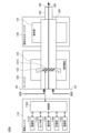
- FIG. 1 is a diagram for explaining an overview of a system according to an embodiment of the present disclosure.
- FIG. 1 is a schematic diagram showing a first configuration example of a suction device according to an embodiment of the present invention.
- FIG. 4 is a schematic diagram showing a second configuration example of the suction device according to the present embodiment.
- 1 is a block diagram showing an example of the configuration of a battery pack according to an embodiment of the present invention;
- FIG. 2 is a block diagram showing an example of the configuration of a user terminal according to the present embodiment.
- 1 is a block diagram showing an example of the configuration of a charging station according to an embodiment of the present invention;
- FIG. 2 is a block diagram showing an example of the configuration of a management server according to the present embodiment.
- FIG. 1 is a schematic diagram showing a first configuration example of a suction device according to an embodiment of the present invention.
- FIG. 4 is a schematic diagram showing a second configuration example of the suction device according to the present embodiment.
- 1 is
- FIG. 11 is a diagram showing an example of a UI screen displayed by a user terminal according to the embodiment.
- FIG. 2 is a sequence diagram showing an example of a flow of processing executed by the system according to the present embodiment.
- FIG. 11 is a diagram showing an example of a UI screen displayed by a user terminal according to the embodiment.
- FIG. 1 is a diagram for explaining an overview of the system according to this embodiment.
- the system 1 according to this embodiment includes a suction device 100, a user terminal 200, a charging station 300, a store terminal 400, and a management server 500.
- the inhalation device 100 is a device that uses a substrate containing an aerosol source to generate an aerosol to be inhaled by the user U.
- the inhalation device 100 may be a so-called electronic cigarette or a heated cigarette.
- the inhalation device 100 can be detachably attached (i.e., connected) to a battery pack 170.
- the inhalation device 100 operates using power from the attached battery pack 170.
- the configuration of the inhalation device 100 with the battery pack 170 removed may be referred to as the main body, or simply as the inhalation device 100.
- the battery pack 170 includes at least a rechargeable secondary battery.
- the battery pack 170 may have a storage medium and a communication terminal. Information may be read and written to the storage medium via the communication terminal by the suction device 100 or the charging station 300 to which the battery pack 170 is connected.
- the user terminal 200 is an example of a terminal device used by the user U.
- the user terminal 200 may be a smartphone or a tablet terminal, etc.
- the user terminal 200 functions as an interface between the user U and the system 1.
- the user terminal 200 inputs and outputs various information for replacing the battery pack 170.
- the user terminal 200 can also control the operation of the suction device 100 through communication with the suction device 100.
- the charging station 300 and the store terminal 400 are placed in a store 8 such as a convenience store, and are used by a store clerk S working at the store 8.
- the charging station 300 and the store terminal 400 placed in the same store 8 may be able to communicate using, for example, a LAN (Local Area Network).
- the store 8 sells substrate packs that contain one or more substrates used by the suction device 100.
- the store 8 may sell multiple types of substrate packs that differ in the types or numbers of substrates contained therein.
- the charging station 300 is an example of a charging device that charges the battery pack 170, and a battery pack providing device that exchangeably provides the charged battery pack 170 to a plurality of suction devices 100.
- the charging station 300 can detachably connect the battery pack 170.
- the charging station 300 charges the connected battery pack 170.
- the charging station 300 includes a storage case 301 that stores the battery pack 170.
- the charging station 300 charges the battery pack 170 stored in the storage case 301.
- the charging station 300 also includes an LED (light emitting diode) 302 and a touch panel 303 that inputs and outputs various information.
- the LED 302 is arranged in correspondence with the storage case 301, and emits light in a color that corresponds to the state of the corresponding storage case 301 (for example, whether it is empty or not, whether it is charging or not, and if it is charging, the progress of charging).
- the user U can exchange the battery pack 170 attached to the suction device 100 at the store 8.
- exchange refers to returning the used battery pack 170 and receiving a charged battery pack 170 from the charging station 300.
- the user U removes the used battery pack 170 from the suction device 100 and returns it.
- the store clerk S connects the battery pack 170 returned by the user U to the charging station 300 to start charging, and removes the charged battery pack 170 from the charging station 300 and provides it to the user U.
- the user U receives the battery pack 170 provided by the store clerk S and attaches it to the suction device 100. With this battery pack 170 exchange service, the user U does not need to charge the battery pack 170 at home, and can exchange the used battery pack 170 for a fully charged battery pack 170 whenever he or she is out and about.
- the charging station 300 may notify the store clerk S by using the LED 302 or the touch panel 303 that an empty storage case 301 is the destination for returning the battery pack 170.
- the charging station 300 may also notify the store clerk S by using the LED 302 or the touch panel 303 to remove the battery pack 170 from the storage case 301 that contains the fully charged battery pack 170 and provide it to the user U.
- the services provided by the charging station 300 are not limited to the replacement of the battery pack 170. That is, the charging station 300 may only accept the return of the battery pack 170, or may only provide the battery pack 170. For example, the user U may borrow a spare battery pack 170 in addition to the battery pack 170 he or she owns, or may return a borrowed spare battery pack 170.
- the battery pack 170 is provided interchangeably to multiple suction devices 100 via the charging station 300.
- the user U can also charge the battery pack 170 at home, etc.
- the store terminal 400 is an example of a terminal device used by the store clerk S.
- the store terminal 400 may be, for example, a cash register terminal that complies with a POS (Point of Sale) system.
- the store terminal 400 functions as an interface between the store clerk S and the system 1.
- the store terminal 400 inputs and outputs various information for replacing the battery pack 170.
- the store terminal 400 also makes payment for the replacement fee of the battery pack 170.
- the battery pack 170 is manufactured and operated so that it has a capacity that can consume at least all of the substrates contained in the substrate pack when the battery pack 170 is fully charged. Therefore, it is desirable to replace the battery pack 170 and purchase a substrate pack at the same time. In that case, the battery pack 170 does not need to be replaced until all of the substrates contained in the substrate pack are consumed.
- the store terminal 400 may notify the store clerk S of information instructing the store clerk S to prompt the user U to replace the battery pack 170.
- the battery pack 170 may be replaced only when the base material pack is purchased, or the cost of replacing the battery pack 170 may be free. With this configuration, it is possible to improve usability by allowing the replacement of the battery pack 170 and the purchase of a base material pack to be carried out at the same time.
- the management server 500 is an example of a control device that controls the overall operation within the system 1.
- the management server 500 communicates with each of the user terminals 200, charging stations 300, and store terminals 400 via the network 9, and controls their operation.
- the management server 500 collects and analyzes various information related to the replacement of the battery pack 170, and based on the analysis results, updates the heating profile and notifies the user U of the timing of replacing the battery pack 170.
- the management server 500 controls the displays of the user terminal 200, the charging station 300, and the store terminal 400.
- the management server 500 collects deteriorated or broken battery packs 170 (i.e., removes them from circulation), and performs processing to repair and re-distribute those that can be repaired.
- the inhalation device 100 is a device that generates a substance to be inhaled by a user.
- the substance generated by the inhalation device 100 is described as an aerosol.
- the substance generated by the inhalation device 100 may be a gas.
- FIG. 2 is a schematic diagram showing a first configuration example of the inhalation device 100 according to the present embodiment.
- the inhalation device 100A includes a power supply unit 110, a cartridge 120, and a flavor imparting cartridge 130.
- the power supply unit 110 includes a power supply section 111A, a sensor section 112A, a notification section 113A, a memory section 114A, a communication section 115A, and a control section 116A.
- the cartridge 120 includes a heating section 121A, a liquid guiding section 122, and a liquid storage section 123.
- the flavor imparting cartridge 130 includes a flavor source 131 and a mouthpiece 124.
- An air flow path 180 is formed in the cartridge 120 and the flavor imparting cartridge 130.
- the power supply unit 111A stores power.
- the power supply unit 111A supplies power to each component of the suction device 100A based on the control of the control unit 116A.
- the power supply unit 111A may be configured, for example, by a rechargeable battery such as a lithium ion secondary battery.
- the sensor unit 112A acquires various information related to the suction device 100A.
- the sensor unit 112A is configured with a pressure sensor such as a condenser microphone, a flow sensor, or a temperature sensor, and acquires values associated with suction by the user.
- the sensor unit 112A is configured with an input device such as a button or switch that accepts information input from the user.
- the notification unit 113A notifies the user of information.
- the notification unit 113A is composed of, for example, a light-emitting device that emits light, a display device that displays an image, a sound output device that outputs sound, or a vibration device that vibrates.
- the storage unit 114A stores various information for the operation of the suction device 100A.
- the storage unit 114A is configured, for example, with a non-volatile storage medium such as a flash memory.
- the communication unit 115A is a communication interface capable of performing communication conforming to any wired or wireless communication standard.
- Such communication standards may include, for example, standards using Wi-Fi (registered trademark), Bluetooth (registered trademark), BLE (Bluetooth Low Energy (registered trademark)), NFC (Near Field Communication), or LPWA (Low Power Wide Area).
- the control unit 116A functions as an arithmetic processing unit and a control unit, and controls the overall operation of the suction device 100A according to various programs.
- the control unit 116A is realized by an electronic circuit such as a CPU (Central Processing Unit) or a microprocessor.
- the liquid storage unit 123 stores the aerosol source.
- the aerosol source is atomized to generate an aerosol.
- the aerosol source is, for example, a liquid such as a polyhydric alcohol such as glycerin and propylene glycol, or water.
- the aerosol source may contain tobacco-derived or non-tobacco-derived flavor components.
- the aerosol source may contain a medicine.
- the liquid guide section 122 guides and holds the aerosol source, which is a liquid stored in the liquid storage section 123, from the liquid storage section 123.
- the liquid guide section 122 is, for example, a wick formed by twisting a fiber material such as glass fiber or a porous material such as porous ceramic. In this case, the aerosol source stored in the liquid storage section 123 is guided by the capillary effect of the wick.
- the heating unit 121A generates an aerosol by heating the aerosol source and atomizing the aerosol source.
- the heating unit 121A is configured as a coil and is wound around the liquid guiding unit 122.
- the heating unit 121A generates heat, the aerosol source held in the liquid guiding unit 122 is heated and atomized, and an aerosol is generated.
- the heating unit 121A generates heat when power is supplied from the power supply unit 111A.
- power may be supplied when the sensor unit 112A detects that the user has started inhaling and/or that specific information has been input. Then, power supply may be stopped when the sensor unit 112A detects that the user has stopped inhaling and/or that specific information has been input.
- the flavor source 131 is a component for imparting flavor components to the aerosol.
- the flavor source 131 may contain tobacco-derived or non-tobacco-derived flavor components.
- the air flow path 180 is a flow path for air inhaled by the user.
- the air flow path 180 has a tubular structure with an air inlet hole 181, which is an entrance of air into the air flow path 180, and an air outlet hole 182, which is an exit of air from the air flow path 180, at both ends.
- the liquid guide section 122 is arranged on the upstream side (the side closer to the air inlet hole 181), and the flavor source 131 is arranged on the downstream side (the side closer to the air outlet hole 182).
- the air flowing in from the air inlet hole 181 as the user inhales is mixed with the aerosol generated by the heating section 121A, and as shown by the arrow 190, is transported through the flavor source 131 to the air outlet hole 182.
- the flavor components contained in the flavor source 131 are imparted to the aerosol.
- the mouthpiece 124 is a member that is held by the user when inhaling.
- An air outlet hole 182 is arranged in the mouthpiece 124.
- the configuration of the suction device 100A is not limited to the above, and various configurations such as those exemplified below are possible.
- the inhalation device 100A may not include a flavoring cartridge 130.
- the cartridge 120 is provided with a mouthpiece 124.
- the suction device 100A may include multiple types of aerosol sources. Multiple types of aerosols generated from the multiple types of aerosol sources may be mixed in the air flow path 180 and undergo a chemical reaction to generate further types of aerosols.
- the means for atomizing the aerosol source is not limited to heating by the heating unit 121A.
- the means for atomizing the aerosol source may be vibration atomization or induction heating.
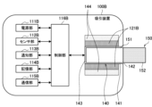
- FIG. 3 is a schematic diagram showing a second configuration example of the suction device 100 according to the present embodiment.
- the suction device 100B according to this configuration example includes a power supply unit 111B, a sensor unit 112B, a notification unit 113B, a storage unit 114B, a communication unit 115B, a control unit 116B, a heating unit 121B, a storage unit 140, and a heat insulating unit 144.
- Each of the power supply unit 111B, the sensor unit 112B, the notification unit 113B, the memory unit 114B, the communication unit 115B, and the control unit 116B is substantially the same as the corresponding components included in the suction device 100A according to the first configuration example.
- the storage section 140 has an internal space 141 and holds the stick-shaped substrate 150 while storing a part of the stick-shaped substrate 150 in the internal space 141.
- the storage section 140 has an opening 142 that connects the internal space 141 to the outside, and stores the stick-shaped substrate 150 inserted into the internal space 141 through the opening 142.
- the storage section 140 is a cylindrical body with the opening 142 and the bottom 143 as its bottom surface, and defines a columnar internal space 141.
- An air flow path that supplies air to the internal space 141 is connected to the storage section 140.
- An air inlet hole which is an air inlet to the air flow path, is arranged, for example, on the side of the suction device 100B.
- An air outlet hole which is an air outlet from the air flow path to the internal space 141, is arranged, for example, on the bottom 143.
- the stick-type substrate 150 includes a substrate portion 151 and a mouthpiece portion 152.
- the substrate portion 151 includes an aerosol source.
- the aerosol source includes a flavor component derived from tobacco or non-tobacco.
- the aerosol source may include a medicine.
- the aerosol source may be, for example, a liquid such as a polyhydric alcohol such as glycerin and propylene glycol, and water, which includes a flavor component derived from tobacco or non-tobacco, or may be a solid containing a flavor component derived from tobacco or non-tobacco.
- the stick-type substrate 150 When the stick-type substrate 150 is held in the storage portion 140, at least a part of the substrate portion 151 is stored in the internal space 141, and at least a part of the mouthpiece portion 152 protrudes from the opening 142.
- the heating section 121B is configured in a film shape and is arranged to cover the outer periphery of the storage section 140.
- the heating section 121B generates heat
- the substrate section 151 of the stick-shaped substrate 150 is heated from the outer periphery, and an aerosol is generated.
- the insulating section 144 prevents heat transfer from the heating section 121B to other components.
- the insulating section 144 is made of a vacuum insulating material or an aerogel insulating material.
- the configuration of the suction device 100B is not limited to the above, and various configurations such as those shown below are possible.
- the heating section 121B may be configured in a blade shape and disposed so as to protrude from the bottom 143 of the storage section 140 into the internal space 141. In that case, the blade-shaped heating section 121B is inserted into the substrate section 151 of the stick-shaped substrate 150 and heats the substrate section 151 of the stick-shaped substrate 150 from the inside. As another example, the heating section 121B may be disposed so as to cover the bottom 143 of the storage section 140. Furthermore, the heating section 121B may be configured as a combination of two or more of a first heating section that covers the outer periphery of the storage section 140, a blade-shaped second heating section, and a third heating section that covers the bottom 143 of the storage section 140.
- the storage unit 140 may include an opening/closing mechanism, such as a hinge, that opens and closes a portion of the outer shell that forms the internal space 141. The storage unit 140 may then open and close the outer shell to accommodate the stick-shaped substrate 150 inserted into the internal space 141 while clamping it.
- the heating unit 121B may be provided at the clamping location in the storage unit 140, and may heat the stick-shaped substrate 150 while pressing it.
- the means for atomizing the aerosol source is not limited to heating by the heating unit 121B.
- the means for atomizing the aerosol source may be induction heating.
- the suction device 100B has at least an electromagnetic induction source such as a coil that generates a magnetic field, instead of the heating unit 121B.
- a susceptor that generates heat by induction heating may be provided in the suction device 100B, or may be included in the stick-shaped substrate 150.
- the suction device 100B may further include the heating unit 121A, the liquid guide unit 122, the liquid storage unit 123, and the air flow path 180 according to the first configuration example, and the air flow path 180 may supply air to the internal space 141.
- the mixed fluid of the aerosol and air generated by the heating unit 121A flows into the internal space 141 and is further mixed with the aerosol generated by the heating unit 121B, and reaches the user's oral cavity.
- the inhalation device 100 is an example of an aerosol generation system that uses a substrate containing either an aerosol source or a flavor source to generate an aerosol to be inhaled by a user.
- the flavor source is a component for imparting flavor components to the aerosol.
- the cartridge 120 and the flavor imparting cartridge 130 are an example of a substrate used by the aerosol generation system.
- the stick-shaped substrate 150 is an example of a substrate used by the aerosol generation system.
- the combination of the inhalation device 100 and the stick-shaped substrate 150 may be considered as an aerosol generation system.
- the battery pack 170 shown in FIG. 1 includes at least the power supply unit 111 shown in FIG. 2 or FIG. 3. Next, an example of the configuration of the battery pack 170 will be described with reference to FIG. 4.
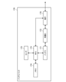
- FIG. 4 is a block diagram showing an example of the configuration of a battery pack 170 according to this embodiment.
- the battery pack 170 includes a battery 171, a protection IC (Integration Circuit) 172, an MCU (Micro Controller Unit) 173, a memory 174, a sensor 175, and a terminal 176.
- a protection IC Integration Circuit
- MCU Micro Controller Unit
- the protection IC 172 is a protection circuit that stops charging in the event of overcharging and stops discharging in the event of over-discharging.
- Memory 174 is an example of a storage unit that stores information.
- Memory 174 is configured, for example, with a non-volatile storage medium such as a flash memory.
- the sensor 175 is an example of a detection unit that detects various information related to the battery pack 170. For example, the sensor 175 detects the temperature of the battery 171, and detects the voltage and current values of the battery 171 when it is being charged and discharged.
- Terminal 176 functions as a power terminal for transmitting and receiving power to and from a device to which battery pack 170 is connected, and as a communication terminal for transmitting and receiving information to and from the device.
- Terminal 176 may be, for example, a Universal Serial Bus (USB) connector.
- USB Universal Serial Bus
- FIG. 4 illustrates an example in which the battery pack 170 includes the protection IC 172
- the protection IC 172 may also be included in the device to which the battery pack 170 is connected (e.g., the main body of the suction device 100 or the charging station 300).
- the control unit 116 controls the operation of the heating unit 121 based on the heating profile.
- the heating profile is control information for controlling the temperature at which the aerosol source is heated.
- the heating profile specifies the target value of a parameter corresponding to the temperature at which the aerosol source is heated.
- An example of the temperature at which the aerosol source is heated is the temperature of the heating unit 121.
- An example of the parameter corresponding to the temperature at which the aerosol source is heated is the resistance of the heating unit 121. That is, the heating profile may specify the target value of the resistance of the heating unit 121 (hereinafter, also referred to as the target resistance).
- the resistance of the heating unit 121 changes depending on the temperature of the heating unit 121 (more precisely, the heating resistor constituting the heating unit 121). In the following, as an example, it is assumed that the resistance of the heating unit 121 increases as the temperature of the heating unit 121 increases.
- the temperature control of the heating section 121 can be achieved, for example, by known feedback control.
- the feedback control may be, for example, PID control (Proportional-Integral-Differential Controller).
- the control section 116 can supply power from the power supply section 111 to the heating section 121 in the form of pulses using pulse width modulation (PWM) or pulse frequency modulation (PFM). In this case, the control section 116 can control the temperature of the heating section 121 by adjusting the duty ratio of the power pulse in the feedback control.
- PWM pulse width modulation
- PFM pulse frequency modulation
- the period during which power supply to the heating unit 121 is controlled based on the heating profile in other words, the period during which heating is performed by the heating unit 121 based on the heating profile, is also referred to as a heating session.
- heating based on the heating profile may be simply referred to as heating.
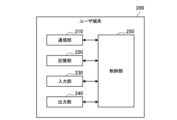
- Example of configuration of user terminal 200> 5 is a block diagram showing an example of the configuration of a user terminal 200 according to this embodiment. As shown in FIG. 5, the user terminal 200 includes a communication unit 210, a storage unit 220, an input unit 230, an output unit 240, and a control unit 250.
- the communication unit 210 is a communication interface for transmitting and receiving information between the user terminal 200 and other devices.
- the communication unit 210 performs communication conforming to any wired or wireless communication standard.
- Such communication standards may include, for example, USB (Universal Serial Bus), Wi-Fi (registered trademark), Bluetooth (registered trademark), or NFC (Near Field Communication).
- the storage unit 220 stores various types of information.
- the storage unit 220 is configured, for example, with a non-volatile storage medium such as a flash memory.
- the input unit 230 has a function of accepting input of various information.
- the input unit 230 may include an input device that accepts input of information from the user U, such as a button, a keyboard, a touch panel, and a microphone.
- the input unit 230 may include a sensor that detects various information. Examples of sensors include a GNSS (Global Navigation Satellite System) receiver that acquires position information of the user terminal 200, a gyro sensor and an acceleration sensor that detect the movement of the user terminal 200, and a camera that can read two-dimensional codes.
- GNSS Global Navigation Satellite System
- the output unit 240 has a function of outputting information.
- the output unit 240 may include an output device that outputs information to the user U.
- Examples of the output device include a display device that displays information, a light-emitting device that emits light, a vibration device that vibrates, and a sound output device that outputs sound.
- An example of a display device is a display.
- An example of a light-emitting device is an LED (Light Emitting Diode).
- An example of a vibration device is an eccentric motor.
- An example of a sound output device is a speaker.
- the control unit 250 functions as a calculation processing device or control device, and controls the overall operation of the user terminal 200 according to various programs.
- the control unit 250 is realized by an electronic circuit such as a CPU (Central Processing Unit) or a microprocessor.
- the control unit 250 may include a ROM (Read Only Memory) that stores the programs and calculation parameters to be used, and a RAM (Random Access Memory) that temporarily stores parameters that change as appropriate.
- the user terminal 200 executes various processes based on the control of the control unit 250.
- the transmission and reception of information by the communication unit 210, the storage and reading of information by the storage unit 220, the processing of information input by the input unit 230, and the output of information by the output unit 240 are examples of processes controlled by the control unit 250.
- Other processes executed by the user terminal 200 such as the input of information to each component and processing based on information output from each component, are also controlled by the control unit 250.
- the functions of the control unit 250 may be realized using an application.
- the application may be pre-installed or may be downloaded.
- the functions of the control unit 250 may be realized by PWA (Progressive Web Apps).
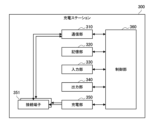
- Configuration example of charging station 300 6 is a block diagram showing an example of the configuration of the charging station 300 according to this embodiment. As shown in FIG. 6, the charging station 300 includes a communication unit 310, a storage unit 320, an input unit 330, an output unit 340, a charging unit 350, one or more connection terminals 351, and a control unit 360.
- the communication unit 310 is a communication interface for transmitting and receiving information between the charging station 300 and other devices.
- the communication unit 310 transmits and receives information to and from the battery pack 170 connected to the connection terminal 351 via the connection terminal 351.
- the communication unit 310 transmits and receives information to and from the management server 500.
- the communication unit 310 performs communication conforming to any wired or wireless communication standard. Examples of such communication standards that may be adopted include USB (Universal Serial Bus), Wi-Fi (registered trademark), Bluetooth (registered trademark), NFC (Near Field Communication), or LAN (Local Area Network).
- the storage unit 320 stores various information.
- the storage unit 320 is configured, for example, with a non-volatile storage medium such as a flash memory.
- the input unit 330 has a function of accepting input of various information.
- the input unit 330 may include an input device that accepts input of information from the store clerk S, such as a button, a keyboard, a touch panel, and a microphone.
- the input unit 330 may include a sensor that detects various information.
- An example of a sensor is a camera that can read two-dimensional codes.
- the touch panel 303 described with reference to FIG. 1 is an example of the input unit 330.
- the output unit 340 has a function of outputting information.
- the output unit 340 may include an output device that outputs information to the store clerk S, such as a display device that displays information, a light-emitting device that emits light, a vibration device that vibrates, and a sound output device that outputs sound.
- An example of a display device is a display.
- An example of a light-emitting device is an LED (Light Emitting Diode).
- An example of a vibration device is an eccentric motor.
- An example of a sound output device is a speaker.
- the LED 302 and touch panel 303 described with reference to FIG. 1 are examples of the output unit 340.
- the charging unit 350 has the function of charging the battery pack 170.
- the charging unit 350 charges the battery pack 170, which is housed in the housing case 301 described with reference to FIG. 1 and is electrically connected to the charging station 300.
- the charging unit 350 charges the battery pack 170 connected to the connection terminal 351.
- the connection terminal 351 is an example of a connection part electrically connected to the battery pack 170.
- the connection terminal 351 functions as a power terminal for transmitting and receiving power and a communication terminal for transmitting and receiving information between the battery pack 170 connected to the connection terminal 351.
- the connection terminal 351 may be, for example, a USB connector.
- the connection terminal 351 is disposed in the housing case 301 and electrically connects to the terminal 176 of the battery pack 170 housed in the housing case 301.
- the charging station 300 may include multiple housing cases 301. That is, the charging station 300 may include multiple connection terminals 351 and charge multiple battery packs 170 simultaneously in parallel.
- the electrical connection between the battery pack 170 and the charging station 300 is not limited to a wired connection, and may be a wireless connection (i.e., wireless charging).
- the entire configuration for charging one battery pack 170 including the storage case 301 and the connection terminal 351, will also be referred to as a charging point.
- the control unit 360 functions as a calculation processing unit or control device, and controls the overall operation of the charging station 300 according to various programs.
- the control unit 360 is realized by an electronic circuit such as a CPU (Central Processing Unit) or a microprocessor.
- the control unit 360 may include a ROM (Read Only Memory) that stores the programs and calculation parameters to be used, and a RAM (Random Access Memory) that temporarily stores parameters that change as appropriate.
- the charging station 300 executes various processes based on the control of the control unit 360. Examples of processes controlled by the control unit 360 include sending and receiving information by the communication unit 310, storing and reading information by the storage unit 320, processing of information input by the input unit 330, output of information by the output unit 340, and starting/stopping charging by the charging unit 350. Other processes executed by the charging station 300, such as input of information to each component and processing based on information output from each component, are also controlled by the control unit 360.
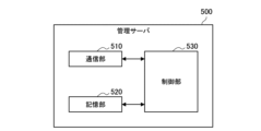
- Example of configuration of management server 500 7 is a block diagram showing an example of the configuration of the management server 500 according to this embodiment. As shown in FIG. 7, the management server 500 includes a communication unit 510, a storage unit 520, and a control unit 530.
- the communication unit 510 is a communication interface for transmitting and receiving information between the management server 500 and other devices.
- the communication unit 510 performs communication conforming to any wired or wireless communication standard.
- the storage unit 520 stores various information for the operation of the management server 500.
- the storage unit 520 is configured, for example, from a non-volatile storage medium such as a hard disc drive (HDD) or a solid state drive (SSD).
- HDD hard disc drive
- SSD solid state drive
- the control unit 530 functions as a calculation processing unit and a control unit, and controls the overall operation of the management server 500 according to various programs.
- the control unit 530 is realized by, for example, a CPU (Central Processing Unit) and electronic circuits such as a microprocessor.
- the control unit 530 may include a ROM (Read Only Memory) that stores the programs and calculation parameters to be used, and a RAM (Random Access Memory) that temporarily stores parameters that change as appropriate.
- the management server 500 executes various processes based on the control of the control unit 530.
- the transmission and reception of information by the communication unit 510, and the storage and reading of information by the storage unit 520 are examples of processes controlled by the control unit 530.
- Other processes executed by the management server 500 such as input of information to each component and processing based on information output from each component, are also controlled by the control unit 530.
- the main body of the suction device 100 or an external device such as the charging station 300 can write various information to the memory 174 when connected to the battery pack 170.
- the MCU 173 writes information received from the external device via the terminal 176 to the memory 174 when connected to the external device.
- the MCU 173 may receive information related to power supply from the battery 171 to the main body of the suction device 100 when the battery pack 170 is connected to the main body of the suction device 100 and write the information to the memory 174 when the battery pack 170 is connected to the main body of the suction device 100.
- the MCU 173 may receive information related to charging of the battery 171 by the charging station 300 when the battery pack 170 is connected to the charging station 300 and write the information to the memory 174 when the battery pack 170 is connected to the charging station 300.
- the battery pack 170 can write information acquired by the battery pack 170 itself to the memory 174.
- the MCU 173 may write information detected by the sensor 175 when the battery pack 170 is connected to the main body of the suction device 100 to the memory 174.
- the MCU 173 may write information detected by the sensor 175 when the battery pack 170 is connected to the charging station 300 to the memory 174.
- the MCU 173 transmits the information stored in the memory 174 to the external device via the terminal 176.
- the external device can perform various processes using the information received from the battery pack 170.
- the charging station 300 transmits the information received by the battery pack 170 to the management server 500.
- the management server 500 In order to improve the quality of the user experience when using the suction device 100, it is preferable for the management server 500 to periodically collect and analyze information related to the suction device 100 and implement measures using the analysis results.
- information related to the suction device 100 is collected by the management server 500 via a user terminal 200 that can communicate with both the suction device 100 and the management server 500.
- the suction device 100 does not communicate with the user terminal 200, or if the user terminal 200 does not communicate with the management server 500, it is difficult to periodically collect information via the user terminal 200.
- the management server 500 can periodically collect information about the suction device 100 via the charging station 300 to which the battery pack 170 is connected when the battery pack 170 is replaced. As a result, it is possible to implement various measures to improve the quality of the user experience when using the suction device 100, thereby improving the quality of the user experience.
- Battery pack ID The memory 174 of the battery pack 170 stores a battery pack ID, which is identification information of the battery pack 170.
- the battery pack ID can be written when the battery pack 170 is manufactured.
- the memory 174 of the battery pack 170 stores specification information that is information indicating the specifications of the battery pack 170.
- the specification information of the battery pack 170 may include a manufacturer ID, which is identification information of the manufacturer that produced the battery pack 170.
- the specification information of the battery pack 170 may include information indicating the manufacturing date of the battery pack 170.
- the specification information of the battery pack 170 may include information indicating the model of the battery pack 170.
- the specification information of the battery pack 170 may include information indicating the initial capacity of the battery 171.
- the memory 174 of the battery pack 170 stores a replacement log that is a log related to replacement of the battery pack 170.
- the replacement log may include at least one of the following pieces of information:
- the exchange log may include a device ID, which is identification information of the suction device 100 to which the battery pack 170 provided by the charging station 300 is connected. Furthermore, the exchange log may include a user ID, which is identification information of a user U of the suction device 100 to which the battery pack 170 provided by the charging station 300 is connected.
- the replacement log may include information indicating the replacement time of the battery pack 170.
- the replacement log may include information indicating the provision time of the battery pack 170 (e.g., the date and time when the battery pack 170 was removed from the charging station 300, or the date and time when the battery pack 170 was connected to the suction device 100).
- the replacement log may also include information indicating the return time of the battery pack 170 (e.g., the date and time when the battery pack 170 was removed from the suction device 100, or the date and time when the battery pack 170 was connected to the charging station 300).
- the replacement log may include information indicating the location where the battery pack 170 is replaced.
- the replacement log may include information indicating the location where the battery pack 170 is provided (e.g., location information or identification information of the store 8).
- the replacement log may also include information indicating the location where the battery pack 170 is returned (e.g., location information or identification information of the store 8).
- the replacement log may include information about the substrate pack purchased along with the replacement of the battery pack 170.
- the substrate pack information may include, for example, the type of substrate and the number of substrates contained in the substrate pack.
- the replacement log may include information indicating the number of times the battery pack 170 has been replaced.
- the number of times the battery pack 170 has been replaced may be incremented each time the battery pack 170 is connected to a different suction device 100 than the previous time. Alternatively, the number of times the battery pack 170 has been replaced may be incremented each time the battery pack 170 is connected to the charging station 300.
- the replacement log may be acquired and written by the main body of the suction device 100, the charging station 300, or the battery pack 170, for example, when replacing the battery pack 170.
- the charging station 300 may acquire such information from the store terminal 400 and write it to the memory 174 of the battery pack 170.
- the memory 174 of the battery pack 170 stores discharge information during heating, which is information indicating the discharge status of the battery 171 when the heating unit 121 performs heating based on the heating profile.
- the discharge information during heating may include at least one of the following pieces of information.
- the discharge information during heating may include a voltage drop value of the battery 171 when the heating unit 121 performs heating.
- the voltage drop value of the battery 171 may be the difference in voltage of the battery 171 before and after heating is performed. Based on such information, it is possible to determine the deterioration state of the battery pack 170 (more specifically, the battery 171) or whether an error has occurred.
- the discharge information during heating may include a decrease in the charge capacity (unit: mAh) of the battery 171 when the heating unit 121 performs heating.
- the decrease in the charge capacity of the battery 171 may be the difference in charge capacity before and after heating is performed, or the difference in charge capacity from the time of manufacture to the present. Such information makes it possible to determine the deterioration state of the battery pack 170 or whether an error has occurred.
- the discharge information during heating may include the temperature rise value of the battery 171 when the heating unit 121 performs heating.
- the temperature rise value of the battery 171 may be the difference between the minimum temperature and the maximum temperature during the heating session. Based on such information, it is possible to determine the deterioration state of the battery pack 170 or whether an error has occurred.
- the discharge information during heating may include a time series change in the amount of discharge during a heating session. Immediately after a puff is performed, the amount of discharge temporarily increases in order to restore the temperature of the heating section 121 that has dropped due to the puff. In this regard, such information makes it possible to determine the number of puffs performed during a heating session.
- the discharge information during heating may include the number of discharges performed for heating. Based on such information, the number of times heating was performed can be determined.
- the discharge information during heating may include the interval between discharges performed for heating. Based on such information, the interval between heating executions can be determined.
- the discharge information during heating may include at least one of the discharge amount or discharge time when heating is performed. Based on such information, the heating profile used by the suction device 100 can be determined.
- the discharge information during heating may include the number of discharges performed for the autorun function.
- the autorun function is a function that starts heating when a substrate is set (e.g., inserted or connected) to the suction device 100 as a trigger. Based on such information, the number of times the autorun function has been performed can be determined.
- the discharge information during heating may include the number of times a discharge abnormality occurred and the amount of discharge when a discharge abnormality occurred. Using such information, errors that occurred in the battery pack 170 can be recorded.
- discharge information during heating can be acquired, for example, by the battery pack 170 or the main body of the suction device 100 and written to the memory 174.
- Discharge information during non-heating The memory 174 of the battery pack 170 stores discharge information during non-heating, which is information indicating the discharge status of the battery 171 during a period when heating based on the heating profile is not being performed.
- the discharge information during non-heating may include at least one of the following pieces of information.
- the discharge information during non-heating may include the number of discharges performed to transition from sleep mode to active mode. Such information makes it possible to determine the number of transitions from sleep mode to active mode.
- sleep mode is an operating mode in which heating is prohibited. In sleep mode, transition to active mode is possible in response to a user operation, such as pressing a button.
- Active mode is an operating mode in which heating is permitted. In active mode, heating is initiated in response to a user operation, such as pressing a button.
- the discharge information during non-heating may include at least one of the discharge amount or discharge time during the period when the communication unit 115 continues communication. Based on such information, the communication amount or communication time of the suction device 100 can be determined.
- Discharge information when not heated can be acquired, for example, by the battery pack 170 or the main body of the suction device 100 and written to the memory 174.
- the memory 174 of the battery pack 170 stores device information that is information indicating the mode of use of the suction device 100.
- the device information may include at least one of the following pieces of information.
- the device information may include information indicating the smoking time.
- Smoking refers to the entire act of the user U inhaling the aerosol generated during heating based on the heating profile. Multiple puffs may be performed during one smoking session.
- the information indicating the smoking time may be the date and time of the start of heating, or the date and time of the first detected puff during a heating session. Such information makes it possible to determine the interval between smoking (i.e., the interval between heating sessions), the number of smoking sessions per day (i.e., the number of heating sessions), and the total number of smoking sessions.
- the device information may include information indicative of smoking time.
- the information indicative of the user U's smoking time may be the length of the heating session or the time from the first detected puff to the last detected puff during the heating session. Such information may be used when customizing a heating profile to suit the user U.
- the device information may include information indicating the total smoking time.
- the total smoking time is the cumulative total of the smoking time since the inhalation device 100 was manufactured. Such information may be used to recommend maintenance timing for the inhalation device 100. In addition, such information may be used to determine the smoking time over the entire life cycle of the inhalation device 100.
- the device information may include information indicating the total number of cigarettes smoked.
- the total number of cigarettes smoked is the cumulative number of cigarettes smoked since the inhalation device 100 was manufactured.
- Such information may be used to recommend maintenance timing for the inhalation device 100.
- such information may be used to determine the number of cigarettes smoked throughout the entire life cycle of the inhalation device 100.
- the device information may include information indicating the total usage time, which is the time that has elapsed since the suction device 100 was first started. Such information may be used to recommend when to perform maintenance on the suction device 100. In addition, such information may be used to determine the usage time of the suction device 100 over its entire life cycle.
- the device information may include information indicating security settings.
- the suction device 100 may be equipped with a security function capable of locking the device for child safety or the like. When the security function is enabled, the suction device 100 operates in a locked state in which heating is prohibited or in an unlocked state in which heating is permitted. The lock may be released by various triggers, such as when a specific button is operated or when a communication connection with the user terminal 200 is established. When the security function is disabled, the suction device 100 is always allowed to heat.
- the information indicating the security settings may include the time when the security function is enabled and the time when the security function is disabled.
- the information indicating the security settings may include information indicating the time when the state transitioned to the locked state, the time when the state transitioned to the unlocked state, and the trigger for unlocking during the period when the security function is enabled.
- the device information may include information indicating the number of puffs, which is the number of puffs detected during a heating session. Such information may be used to determine the number of puffs a user U takes per smoking session. Such information may be used to customize a heating profile to suit the user U.
- the device information may include information indicating a puff time, which is the time when a puff is detected during a heating session. Such information may determine when the user U puffs during a heating session. Such information may be used to customize a heating profile to suit the user U.
- the device information may include location information of the inhalation device 100. More specifically, the device information may include time series changes in the location information of the inhalation device 100.
- the location information of the user terminal 200 may be used as the location information of the inhalation device 100. According to such information, the behavioral pattern of the user U can be determined. The behavioral pattern of the user U can be used when the user terminal 200 suggests a smoking area or store 8 that matches the behavioral pattern of the user U.
- the device information may include information indicating an error that has occurred in the suction device 100. Such information may be used to recommend when to perform maintenance on the suction device 100.
- the device information can be obtained, for example, by the battery pack 170 or the main body of the suction device 100 and written to the memory 174.
- the memory 174 of the battery pack 170 stores charging information, which is information indicating the charging status of the battery 171.
- the charging information may include at least one of the following pieces of information:
- the charging information may include information indicating the number of times the battery pack 170 has been charged. The number of times the battery pack 170 has been connected to the charging station 300 or a home charger. Based on such information, the deterioration state of the battery pack 170 can be determined.
- the charging information may include information indicating the charging interval.
- the charging interval refers to the time that elapses between when the battery pack 170 is removed from the charging station 300 or a home charger, etc. and when it is reconnected. Based on such information, the deterioration state of the battery pack 170 can be determined.
- the charging information may include information indicating the charging time and the amount of charge per charge.
- the charging time refers to the date and time when the battery pack 170 is connected to the charging station 300 or a home charger.
- the amount of charge per charge refers to the voltage increase value during charging. Based on such information, the status of each charge and the deterioration state of the battery pack 170 can be determined.
- the charging information may include information indicating the charging voltage or charging current.
- the charging voltage refers to the voltage value applied to the battery 171 during charging.
- the charging current refers to the current value that flows through the battery 171 during charging. Such information makes it possible to determine the device (charging station 300 or home charger) that charged the battery pack 170.
- the charging information may include location information at the time of charging. Such information may enable the location where the battery pack 170 was charged (e.g., store 8 or home).
- the charging information may include information indicating the number of times a charging abnormality occurred and the amount of charge when the charging abnormality occurred. Such information can be used to record errors that have occurred in the battery pack 170.
- the charging information may include information indicating the SOH (States Of Health) of the battery 171. Such information makes it possible to determine the deterioration state of the battery 171.
- SOH States Of Health
- the charging information can be obtained, for example, by the battery pack 170 or the charging station 300 and written to the memory 174.
- the battery pack 170 can store and transmit at least two or more of the battery pack ID, replacement log, discharge information when heated, discharge information when not heated, device information, and charging information in association with each other.
- Such a configuration allows for more precise analysis of collected information. For example, by associating the replacement log with the discharge information when heated, it becomes possible to analyze the discharge status when heated of the suction device 100 identified by the device ID included in the replacement log.
- the management server 500 controls a process of recommending a candidate replacement location (i.e., a charging station 300) for the battery pack 170 to the user U.
- the management server 500 selects one or more charging stations 300 as a candidate replacement location for the battery pack 170 from among a plurality of charging stations 300 that can provide the battery pack 170.
- the management server 500 recommends the selected candidate replacement location for the battery pack 170 to the user U.
- the management server 500 generates a UI screen in which the positions of the candidate replacement locations for the battery pack 170 are mapped on a map, and displays the UI screen on the user terminal 200. According to this configuration, it is possible to urge the user U to replace the battery pack 170 at an appropriate charging station 300, thereby improving the usability for the user U.
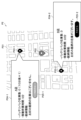
- FIG. 8 is a diagram showing an example of a UI screen displayed by the user terminal 200 according to this embodiment.
- the UI screen P1 displays a pin P12 and a pin P13 (P13-1 and P13-2) superimposed on a map P11 around the current location of the user U.
- the pin P12 indicates the current location of the user U.
- the pin P13 indicates the location of a charging station 300 recommended as a candidate for a battery pack 170 replacement location.
- the number of charging stations 300 displayed is not particularly limited, and may be two as shown in FIG. 8, or may be unlimited.
- the user U can refer to the UI screen P1 and try replacing the battery pack 170 at a convenient charging station 300.
- annotations P14 (P14-1 and P14-2) indicating information on the charging station 300 or the store 8 in which the charging station 300 is located are displayed in association with each charging station 300.
- the annotations P14 include information indicating the name of the store 8, the number of replaceable (i.e., fully charged) battery packs 170 in stock, the time required for the user U to travel from the user U's current location to the charging station 300, and whether or not the user U's preferred brand of base material pack is in stock.
- the user U can select a store 8 that has a stock of replaceable battery packs 170, has a short travel time, or has a stock of the preferred brand of base material pack as the battery pack 170 replacement location.
- the UI screen P1 may display the future stock number, such as the number of available battery packs 170 in stock increasing by one in 10 minutes, as shown in the annotation P14-1.
- user U can select the store 8 to visit in anticipation of future increases in inventory.
- the above describes an example of a UI screen displayed by the user terminal 200.
- the management server 500 may collect information stored in the memory 174 of the battery pack 170 via the charging station 300, and may recommend candidate replacement locations for the battery pack 170 based on such information.
- the management server 500 may collect information stored in the memory 174 of the battery pack 170 in real time via the suction device 100 to which the battery pack 170 is connected, and may recommend candidate replacement locations for the battery pack 170 based on such information.
- the management server 500 may collect information on the suction device 100 or the charging station 300 in real time from the suction device 100 or the management server 500 itself, and may recommend candidate replacement locations for the battery pack 170 based on such information. Details of the process of recommending candidate replacement locations for the battery pack 170 are described below.
- the management server 500 may execute a process of recommending potential replacement locations for the battery pack 170 based on information indicating the remaining battery power of the battery pack 170 connected to the inhalation device 100. For example, the management server 500 recommends potential replacement locations for the battery pack 170 before the remaining battery power of the battery pack 170 connected to the inhalation device 100 runs out. With this configuration, it is possible to urge the user U to replace the battery pack 170 with ample time to spare, and to prevent a situation in which the remaining battery power of the battery pack 170 runs out and the user is unable to smoke.
- the management server 500 executes a process of recommending a candidate replacement location for the battery pack 170.
- the first threshold is set to a value equal to or greater than the remaining battery charge that allows one or more substrates to be consumed. That is, the management server 500 may recommend a candidate replacement location for the battery pack 170 when the remaining battery charge of the battery pack 170 reaches a level that allows a predetermined number of substrates to be consumed.
- the management server 500 may set the first threshold based on information indicating the heating profile used by the suction device 100. For example, the management server 500 may set the first threshold high for a suction device 100 that uses a heating profile with relatively high temperatures and high power consumption. On the other hand, the management server 500 may set the first threshold low for a suction device 100 that uses a heating profile with relatively low temperatures and low power consumption. With this configuration, it is possible to prompt the user U to replace the battery pack 170 at an appropriate timing according to the power consumption for each heating profile.
- the management server 500 may set the first threshold value based on the usage of the inhalation device 100. For example, the management server 500 may set the first threshold value high for a user U whose smoking intervals are short. On the other hand, the management server 500 may set the first threshold value low for a user U whose smoking intervals are long. With this configuration, it is possible to prompt the user U to replace the battery pack 170 at an appropriate timing according to the usage of the inhalation device 100.
- the timing for recommending potential replacement locations for the battery pack 170 can be determined based on a variety of information in addition to, or in place of, the remaining battery charge of the battery pack 170 connected to the suction device 100.
- the management server 500 may execute a process of recommending candidate replacement locations for the battery pack 170 when the number of substrates carried with the inhalation device 100 is less than the second threshold value.
- the number of substrates carried with the inhalation device 100 may be input by the user U to the user terminal 200, or may be estimated based on information on substrate packs purchased by the user U and the number of times the user has smoked since purchasing the substrate packs.
- the user U is prompted to replace the battery pack 170 before the substrates carried by the user U run out, and is prompted to purchase a substrate pack at the same time as replacing the battery pack 170.
- the management server 500 may set the second threshold based on information indicating the usage mode of the inhalation device 100. For example, the management server 500 may set the second threshold high for a user U with a short smoking interval, and set the second threshold low for a user U with a long smoking interval. With this configuration, it is possible to prompt the user U to replace the battery pack 170 at an appropriate timing according to the consumption pace of the base material for each user U.
- the management server 500 may execute a process of recommending candidate locations for replacing the battery pack 170 when an abnormality occurs in the battery pack 170 connected to the suction device 100. Whether or not an abnormality has occurred in the battery pack 170 may be input by the user U to the user terminal 200, or may be determined based on discharge information or charging information during heating. With this configuration, it is possible to urge the user U to replace the battery pack 170 in which an abnormality has occurred, and to prevent the use of the battery pack 170 in which an abnormality has occurred.
- the management server 500 may recommend multiple charging stations 300 as candidate locations for replacing the battery pack 170. In doing so, the management server 500 may recommend multiple charging stations 300 in accordance with a priority order based on a predetermined criterion. An example of the priority order setting criteria is described below.
- the management server 500 may preferentially recommend charging stations 300 having battery packs 170 that can be provided to the suction device 100 (i.e., fully charged) as potential locations for replacing the battery packs 170. Furthermore, the management server 500 may preferentially recommend charging stations 300 that have a larger stock of battery packs 170 that can be provided to the suction device 100 as potential locations for replacing the battery packs 170. This configuration makes it possible to prevent inconveniences such as the user U visiting the store 8 but being unable to replace the battery pack 170 because it is out of stock.
- the management server 500 may preferentially recommend charging stations 300 that can return the battery pack 170 used by the suction device 100 as potential replacement locations for the battery pack 170.
- the management server 500 preferentially recommends charging stations 300 that have available charging points as potential replacement locations for the battery pack 170. This configuration makes it possible to prevent inconveniences such as the user U visiting the store 8 but not being able to return the battery pack 170, and therefore not being able to replace the battery pack 170.
- the management server 500 may select a candidate replacement location for the battery pack 170 based on the scheduled charging end time for each of one or more charging points that the charging station 300 has and the expected arrival time of the user U at the charging station 300. For example, the management server 500 may first obtain the scheduled charging end time for each charging point estimated by the charging station 300. The management server 500 may also estimate the expected arrival time of the user U at the charging station 300 based on the current location of the user U indicated by the location information of the user terminal 200 and the location information of the store 8 in which the charging station 300 is located.
- the management server 500 may determine that the charging station 300 has a stock of battery packs 170 that can be provided, and may recommend the charging station 300 as a candidate replacement location for the battery pack 170. With this configuration, even if there is no battery pack 170 currently in stock, it is possible to recommend a charging station 300 that is expected to have battery packs 170 in stock by the time the user U arrives as a candidate location for replacing the battery pack 170.
- the management server 500 may preferentially recommend a charging station 300 that is geographically close to the user U as a candidate replacement location for the battery pack 170.
- the management server 500 may preferentially recommend a charging station 300 that is located within a predetermined distance from the current location of the user U, which is indicated by the location information of the user terminal 200, as a candidate replacement location for the battery pack 170.
- the management server 500 may preferentially recommend a charging station 300 that is closest to the current location of the user U as a candidate replacement location for the battery pack 170. With this configuration, it is possible to encourage the user U to replace the battery pack 170 at the nearest charging station 300.
- the management server 500 may preferentially recommend a charging station 300 located in a store 8 that has stock of the base material used by the suction device 100 as a candidate replacement location for the battery pack 170.
- the management server 500 may preferentially recommend a charging station 300 located in a store 8 that has stock of a base material pack that the user U recently purchased or that the user U purchases frequently as a candidate replacement location for the battery pack 170.
- the user U can purchase a preferred base material pack in addition to replacing the battery pack 170.
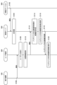
- FIG. 9 is a sequence diagram showing an example of the flow of processing executed by the system 1 according to this embodiment. This sequence involves the suction device 100, the user terminal 200, the charging station 300, and the management server 500.
- the charging station 300 reports various information to the management server 500 (step S102).
- the charging station 300 transmits to the management server 500 the usage status of each charging point, the progress of charging the battery pack 170, and the scheduled end time of charging.
- the charging station 300 transmits information collected from the connected battery pack 170 to the management server 500.
- the management server 500 stores the information received from the charging station 300 in a database (hereinafter also referred to as DB) to update the DB that manages the information of the charging station 300 (step S104).
- the DB further stores the number of charging points that the charging station 300 has, the location information of the store 8 in which the charging station 300 is located, and the like.
- the suction device 100 reports various information to the user terminal 200 (step S106). For example, the suction device 100 transmits information indicating the remaining battery power of the battery pack 170 connected to the suction device 100 to the user terminal 200.
- the user terminal 200 accepts user input (step S108).
- the user terminal 200 accepts input of the number of substrates that the user U is carrying with the suction device 100.
- the user terminal 200 acquires location information indicating the current location of the user U (step S110).
- the user terminal 200 reports various information to the management server 500 (step S112).
- the user terminal 200 transmits to the management server 500 the information received from the suction device 100 in step S106, the information input by the user U in step S108, and the location information acquired in step S110.
- the management server 500 determines whether or not it is necessary to recommend a candidate replacement location for the battery pack 170 (step S114). For example, when the remaining battery charge of the battery pack 170 connected to the suction device 100 is less than the first threshold, the management server 500 determines that it is necessary to recommend a candidate replacement location for the battery pack 170.
- the management server 500 selects one or more charging stations 300 as candidate replacement locations for the battery pack 170 (step S116). For example, the management server 500 refers to the DB updated in step S104 and selects, as a candidate replacement location for the battery pack 170, a charging station 300 that has an inventory of available battery packs 170 and is within a predetermined distance from the current location of the user U.
- the management server 500 transmits information indicating candidate replacement locations for the selected battery pack 170 to the user terminal 200 (step S118).
- the user terminal 200 displays a UI screen showing potential locations for replacing the battery pack 170 (step S120).
- the management server 500 may control a process of reserving the battery pack 170 owned by a candidate replacement location for the battery pack 170.
- the management server 500 reserves, for the user U, the inventory of the battery pack 170 in the charging station 300 selected by the user U from among the charging stations 300 recommended to the user U as candidate replacement locations for the battery pack 170. With such a configuration, it is possible to improve usability.
- the reservation of the battery pack 170 can be performed on a UI screen displayed by the user terminal 200.
- An example of a UI screen related to reservation is described below with reference to FIG. 10.
- FIG. 10 is a diagram showing an example of a UI screen displayed by the user terminal 200 according to this embodiment.
- the UI screen P2 displays a pin P22 and a pin P23 (P23-1 and P23-2) superimposed on a map P21 of the area around the current location of the user U.
- the pin P22 indicates the current location of the user U.
- the pin P23 indicates the location of a charging station 300 recommended as a candidate location for replacing the battery pack 170.
- annotations P24 (P24-1 and P24-2) indicating information about the charging station 300 or the store 8 in which the charging station 300 is located are displayed in association with each charging station 300.
- the annotations P24 include the same content as the annotations P14 shown in FIG. 8, and further include a reservation button P25 (P25-1 and P25-2).
- the user U can reserve the replacement of the battery pack 170 at the charging station 300 by selecting the reservation button P25.
- the reservation button P25-1 for the charging station 300 at store A which currently has no replaceable battery packs 170 in stock and is predicted to have no stock in five minutes, which is the travel time, is inactivated and cannot be selected.
- the reservation button P25-2 for the charging station 300 at store B which currently has replaceable battery packs 170 in stock, is activated and can be selected.
- the management server 500 When the management server 500 accepts a reservation, it secures the reserved battery pack 170 and controls the charging station 300 to provide the secured battery pack 170 only to the user U who made the reservation.
- the charging station 300 may lock the storage case 301 that contains the reserved battery pack 170, or cause the LED 302 corresponding to the storage case 301 to emit light in a predetermined manner.
- the charging station 300 may provide the reserved battery pack 170 only if it is authenticated that the user U who has come to receive the battery pack 170 is the user U who made the reservation.
- the authentication may be performed, for example, by the user terminal 200 displaying a two-dimensional code issued by the management server 500 at the time of reservation and the charging station 300 reading it.
- the management server 500 may cancel the reservation if the user U who made the reservation does not receive the reserved battery pack 170 within a specified time.
- the management server 500 When the management server 500 accepts a reservation, it may notify the user terminal 200 of information indicating that the reservation acceptance has been completed. In addition, when the management server 500 cancels a reservation, it may notify the user terminal 200 of information indicating that the reservation has been cancelled.
- the suction device 100 communicates with the management server 500 via the user terminal 200 or the charging station 300, but the present disclosure is not limited to such an example.
- the suction device 100 may also communicate directly with the management server 500.
- the charging station 300 is operated by a store clerk S, but the present disclosure is not limited to such an example.
- the charging station 300 may be operated by a user U through self-service. In other words, the store clerk S does not need to be involved in replacing the battery pack 170.
- the system 1 includes a store terminal 400, but the present disclosure is not limited to such an example.
- the function of the store terminal 400 may be included in the user terminal 200. In that case, the replacement cost of the battery pack 170 may be paid by electronic payment by the user terminal 200.
- the function of the store terminal 400 may be included in the charging station 300.
- the power supply unit 111 of the suction device 100 may be charged by a portable charger with a built-in battery that is configured to be detachable from the suction device 100.
- An exchange service for the portable charger may be provided, and the technology related to the present disclosure may be applied by regarding the portable charger as a battery pack in the present disclosure.
- the charging station 300 may recommend candidate exchange locations for the portable charger to the user U.
- the processes described in the above embodiment may be executed mainly by any device.
- the determination of whether or not a candidate replacement location for the battery pack 170 needs to be recommended may be performed by the user terminal 200.
- the user terminal 200 may transmit a request to the management server 500 requesting that a replacement location for the battery pack 170 be recommended, and upon receiving the request, the management server 500 may select a replacement location for the battery pack 170 and respond to the user terminal 200.
- the series of processes performed by each device described in this specification may be realized using software, hardware, or a combination of software and hardware.
- the programs constituting the software are stored in advance, for example, in a recording medium (more specifically, a non-transient storage medium readable by a computer) provided inside or outside each device.
- a recording medium more specifically, a non-transient storage medium readable by a computer
- Each program is loaded into a RAM (Random Access Memory) when executed by a computer that controls each device described in this specification, and executed by a processing circuit such as a CPU (Central Processing Unit).
- the recording medium is, for example, a magnetic disk, an optical disk, a magneto-optical disk, a flash memory, etc.
- the computer program may be distributed, for example, via a network without using a recording medium.
- the computer may be an application-specific integrated circuit such as an ASIC (application specific integrated circuit), a general-purpose processor that executes functions by reading a software program, or a computer on a server used in cloud computing.
- ASIC application specific integrated circuit
- the series of processes performed by each device described in this specification may be processed in a centralized manner by a single computer, or may be processed in a distributed manner by multiple computers.
- two or more communication means present in one device may be physically realized by a single medium.
- a control unit that selects one or more of a plurality of battery pack providing devices capable of providing a battery pack replaceably connected to an inhalation device that generates an aerosol using a base material containing an aerosol source as a candidate replacement location for the battery pack, and controls a process of recommending the selected candidate replacement location for the battery pack to a user of the inhalation device;
- a control device comprising: (2) the control unit executes a process of recommending a candidate replacement location for the battery pack based on information indicating a remaining battery level of the battery pack currently connected to the suction device.
- the control unit executes a process of recommending a candidate replacement location for the battery pack when a remaining battery charge of the battery pack connected to the suction device is less than a first threshold value;
- the first threshold is set to a value equal to or greater than a value corresponding to a remaining battery capacity at which one or more of the substrates can be consumed.
- the control unit sets the first threshold value based on control information for controlling a temperature at which the inhalation device heats the aerosol source.
- the control unit sets the first threshold value based on a usage mode of the suction device.
- the control unit executes a process of recommending a candidate replacement location for the battery pack when the number of the base materials carried together with the suction device is less than a second threshold value.
- the control device according to any one of (3) to (5).
- the control unit executes a process of recommending a candidate replacement location for the battery pack when an abnormality occurs in the battery pack connected to the suction device.
- the control unit preferentially recommends the battery pack providing device having the battery pack that can be provided to the suction device as a candidate replacement location for the battery pack.
- the control unit preferentially recommends the battery pack providing device capable of returning the battery pack used by the suction device as a candidate replacement location for the battery pack.
- the control unit recommends candidates for the battery pack exchange location based on a scheduled charging end time for each of one or more charging points included in the battery pack providing device and a scheduled arrival time of the user of the suction device at the battery pack providing device.
- the control unit preferentially recommends the battery pack providing apparatus that is geographically close to the user as a candidate replacement location for the battery pack.
- the control unit preferentially recommends the battery pack providing device disposed in a store that has an inventory of the base material used by the suction device as a candidate replacement location for the battery pack.
- the control device according to any one of (1) to (11).
- the control unit controls a process of reserving the battery pack owned by the battery pack replacement location candidate.
- a processor-implemented control method comprising: selecting one or more of a plurality of battery pack providing devices capable of providing a battery pack replaceably connected to an inhalation device that generates an aerosol using a base material containing an aerosol source as a candidate replacement location for the battery pack, and controlling a process of recommending the selected candidate replacement location for the battery pack to a user of the inhalation device;
- a control method comprising: (15) Computer, a control unit that selects one or more of a plurality of battery pack providing devices capable of providing a battery pack replaceably connected to an inhalation device that generates an aerosol using a base material containing an aerosol source as a candidate replacement location for the battery pack, and controls a process of recommending the selected candidate replacement location for the battery pack to a user of the inhalation device;
Landscapes
- Engineering & Computer Science (AREA)
- Power Engineering (AREA)
- Charge And Discharge Circuits For Batteries Or The Like (AREA)
- Human Computer Interaction (AREA)
Priority Applications (4)
| Application Number | Priority Date | Filing Date | Title |
|---|---|---|---|
| CN202380104626.4A CN122374954A (zh) | 2023-12-13 | 2023-12-13 | 控制装置、控制方法和程序 |
| JP2025563141A JPWO2025126385A1 (cg-RX-API-DMAC7.html) | 2023-12-13 | 2023-12-13 | |
| PCT/JP2023/044695 WO2025126385A1 (ja) | 2023-12-13 | 2023-12-13 | 制御装置、制御方法及びプログラム |
| KR1020267017968A KR20260109900A (ko) | 2023-12-13 | 2023-12-13 | 제어 장치, 제어 방법, 및 프로그램 |
Applications Claiming Priority (1)
| Application Number | Priority Date | Filing Date | Title |
|---|---|---|---|
| PCT/JP2023/044695 WO2025126385A1 (ja) | 2023-12-13 | 2023-12-13 | 制御装置、制御方法及びプログラム |
Publications (1)
| Publication Number | Publication Date |
|---|---|
| WO2025126385A1 true WO2025126385A1 (ja) | 2025-06-19 |
Family
ID=96056830
Family Applications (1)
| Application Number | Title | Priority Date | Filing Date |
|---|---|---|---|
| PCT/JP2023/044695 Pending WO2025126385A1 (ja) | 2023-12-13 | 2023-12-13 | 制御装置、制御方法及びプログラム |
Country Status (4)
| Country | Link |
|---|---|
| JP (1) | JPWO2025126385A1 (cg-RX-API-DMAC7.html) |
| KR (1) | KR20260109900A (cg-RX-API-DMAC7.html) |
| CN (1) | CN122374954A (cg-RX-API-DMAC7.html) |
| WO (1) | WO2025126385A1 (cg-RX-API-DMAC7.html) |
Citations (4)
| Publication number | Priority date | Publication date | Assignee | Title |
|---|---|---|---|---|
| WO2014163664A1 (en) | 2013-04-05 | 2014-10-09 | Johnson Creek Enterprises, LLC | Method and apparatus for controlling electronic cigarette |
| JP2015015827A (ja) * | 2013-07-04 | 2015-01-22 | レスク株式会社 | 電動車両用バッテリ交換システム及びプログラム |
| JP2017091427A (ja) * | 2015-11-17 | 2017-05-25 | オムロン株式会社 | バッテリ予約装置 |
| WO2022130468A1 (ja) * | 2020-12-14 | 2022-06-23 | 日本たばこ産業株式会社 | 吸引装置、端末装置、及びプログラム |
-
2023
- 2023-12-13 JP JP2025563141A patent/JPWO2025126385A1/ja active Pending
- 2023-12-13 CN CN202380104626.4A patent/CN122374954A/zh active Pending
- 2023-12-13 WO PCT/JP2023/044695 patent/WO2025126385A1/ja active Pending
- 2023-12-13 KR KR1020267017968A patent/KR20260109900A/ko active Pending
Patent Citations (4)
| Publication number | Priority date | Publication date | Assignee | Title |
|---|---|---|---|---|
| WO2014163664A1 (en) | 2013-04-05 | 2014-10-09 | Johnson Creek Enterprises, LLC | Method and apparatus for controlling electronic cigarette |
| JP2015015827A (ja) * | 2013-07-04 | 2015-01-22 | レスク株式会社 | 電動車両用バッテリ交換システム及びプログラム |
| JP2017091427A (ja) * | 2015-11-17 | 2017-05-25 | オムロン株式会社 | バッテリ予約装置 |
| WO2022130468A1 (ja) * | 2020-12-14 | 2022-06-23 | 日本たばこ産業株式会社 | 吸引装置、端末装置、及びプログラム |
Also Published As
| Publication number | Publication date |
|---|---|
| CN122374954A (zh) | 2026-07-10 |
| JPWO2025126385A1 (cg-RX-API-DMAC7.html) | 2025-06-19 |
| KR20260109900A (ko) | 2026-07-13 |
Similar Documents
| Publication | Publication Date | Title |
|---|---|---|
| US20250295176A1 (en) | Smoking substitute devices and associated methods, systems and apparatuses | |
| JP7633266B2 (ja) | 吸引装置、制御方法、及びプログラム | |
| JP7675732B2 (ja) | 吸引装置、システム、及びプログラム | |
| EP3733023A1 (en) | Aerosol aspirator brand designation system | |
| JP7685067B2 (ja) | エアロゾル生成装置の通知制御装置、エアロゾル生成装置の通知制御方法、及びエアロゾル生成装置の制御プログラム | |
| US20230000152A1 (en) | Inhaling device, control method, and non-transitory computer readable medium | |
| JP7529803B2 (ja) | 制御方法、吸引装置、端末装置、及びプログラム | |
| JP7579349B2 (ja) | システム、端末装置、制御方法、及びプログラム | |
| EP4014769A1 (en) | Inhalation device, control method, and program | |
| JP2025157516A (ja) | 情報処理装置、情報処理システム、情報処理端末、情報処理方法及びプログラム | |
| CN117500399A (zh) | 气溶胶供应系统 | |
| WO2025126382A1 (ja) | バッテリパック及び制御装置 | |
| JP7544833B2 (ja) | 販売システム、吸引装置、販売端末、及び販売方法 | |
| WO2025126383A1 (ja) | バッテリパック、情報処理方法及びプログラム | |
| WO2025126384A1 (ja) | バッテリパック提供装置、制御方法及びプログラム | |
| WO2025126381A1 (ja) | 制御装置及び端末装置 | |
| EP4230070A1 (en) | Inhalation device, terminal device, and program | |
| EP4018856A1 (en) | Terminal device, suction device, information processing method, and program | |
| JP7701436B2 (ja) | 制御装置、端末装置及び情報処理方法 | |
| WO2025141726A1 (ja) | エアロゾル生成装置 | |
| WO2025141723A1 (ja) | 制御方法、情報処理装置、通信端末、及びバッテリレンタルサービス支援システム | |
| JP7529899B2 (ja) | 制御装置、端末装置及び情報処理方法 | |
| JP7544834B2 (ja) | 販売システム、吸引装置、情報処理装置、販売方法、及びプログラム | |
| JP7549039B2 (ja) | 吸引装置、端末装置、及びプログラム | |
| JP7355845B2 (ja) | 制御装置、制御方法、及びプログラム |
Legal Events
| Date | Code | Title | Description |
|---|---|---|---|
| 121 | Ep: the epo has been informed by wipo that ep was designated in this application |
Ref document number: 23961451 Country of ref document: EP Kind code of ref document: A1 |
|
| ENP | Entry into the national phase |
Ref document number: 2025563141 Country of ref document: JP Kind code of ref document: A |
|
| ENP | Entry into the national phase |
Ref document number: 1020267017968 Country of ref document: KR Free format text: ST27 STATUS EVENT CODE: A-0-1-A10-A15-NAP-PA0105 (AS PROVIDED BY THE NATIONAL OFFICE) |
|
| WWE | Wipo information: entry into national phase |
Ref document number: 1020267017968 Country of ref document: KR |
|
| WWP | Wipo information: published in national office |
Ref document number: 1020267017968 Country of ref document: KR |
|
| NENP | Non-entry into the national phase |
Ref country code: DE |