WO2025120899A1 - 穿孔器およびガス排出装置 - Google Patents
穿孔器およびガス排出装置 Download PDFInfo
- Publication number
- WO2025120899A1 WO2025120899A1 PCT/JP2024/026458 JP2024026458W WO2025120899A1 WO 2025120899 A1 WO2025120899 A1 WO 2025120899A1 JP 2024026458 W JP2024026458 W JP 2024026458W WO 2025120899 A1 WO2025120899 A1 WO 2025120899A1
- Authority
- WO
- WIPO (PCT)
- Prior art keywords
- piston
- perforator
- cutting edge
- sealing plate
- piston rod
- Prior art date
- Legal status (The legal status is an assumption and is not a legal conclusion. Google has not performed a legal analysis and makes no representation as to the accuracy of the status listed.)
- Pending
Links
Images




Classifications
-
- F—MECHANICAL ENGINEERING; LIGHTING; HEATING; WEAPONS; BLASTING
- F17—STORING OR DISTRIBUTING GASES OR LIQUIDS
- F17C—VESSELS FOR CONTAINING OR STORING COMPRESSED, LIQUEFIED OR SOLIDIFIED GASES; FIXED-CAPACITY GAS-HOLDERS; FILLING VESSELS WITH, OR DISCHARGING FROM VESSELS, COMPRESSED, LIQUEFIED, OR SOLIDIFIED GASES
- F17C7/00—Methods or apparatus for discharging liquefied, solidified, or compressed gases from pressure vessels, not covered by another subclass
Definitions
- the present invention relates to a perforator and a gas discharge device for discharging gas from a gas bottle.
- This type of perforator when attached to the gas bottle, has a piston with a cutting edge at the tip that faces the sealing plate, and a drive unit that launches the piston toward the sealing plate when activated.
- Patent Document 1 discloses a perforator equipped with a piston rod having a cutting edge at the tip that is V-shaped when viewed from the side.
- the technology disclosed herein has been made in consideration of the above-mentioned circumstances, and aims to provide a technology that prevents a sealing plate from being torn off when the sealing plate is pierced by the cutting edge of a piston rod in a perforator for discharging gas from a gas bottle.
- the technology according to the present disclosure is a perforator that is used in a state in which a gas bottle is attached, and that, when activated, opens a sealing plate that seals a gas outlet in the gas bottle, thereby discharging gas from the gas bottle, a piston rod having a cutting edge at a tip end thereof, the cutting edge being disposed opposite the sealing plate when the perforator is attached to the gas bottle; a drive unit that, when actuated, propels the piston rod toward the sealing plate and causes the cutting edge to pierce the sealing plate; Equipped with The cutting edge portion has a plurality of ridges and three or more piston blade surfaces separated from one another by the ridges.
- the cutting edge portion may include a tip ridge that forms the tip of the cutting edge portion, and the projected length of the tip ridge along the axial direction of the piston rod may be smaller than the diameter of the piston rod.
- one end of another ridge may be connected to both ends of the tip ridge.
- the other end of the other ridge may also extend to the side of the piston rod.
- At least one end of the tip edge may be connected to a plurality of the other edges.
- each of the multiple ridges may meet at an apex formed at the tip of the cutting edge, and the other end of each ridge may extend to the side of the piston rod.
- the technology disclosed herein may also be a gas discharge device that includes any of the perforators described above and a gas bottle that can be attached to the perforator.
- the present disclosure provides a technology that prevents a sealing plate from being torn off when the sealing plate is pierced by the cutting edge of a piston rod in a perforator for discharging gas from a gas bottle.
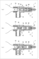
- FIG. 1 is a diagram showing an example of the configuration of a perforator according to an embodiment.
- FIG. 2 is a diagram showing an example of the configuration of a gas bottle according to the embodiment.
- FIG. 3 is a diagram illustrating the operation of the perforator according to the embodiment.
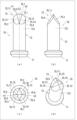
- FIG. 4 is a diagram illustrating a detailed structure of the second piston according to the embodiment.
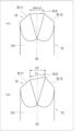
- FIG. 5 is a diagram for explaining the length of the tip ridgeline projected in the axial direction.
- FIG. 6 is a diagram illustrating a piston rod according to a first comparative example.
- FIG. 7 is a diagram illustrating a state in which a sealing plate of a gas bottle is pierced by a cutting edge of a piston rod according to an embodiment.
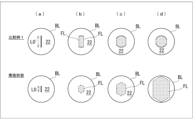
- FIG. 8 is a diagram for comparing the state of perforations in the sealing plate in the embodiment and the comparative example.
- FIG. 9 is a diagram illustrating a piston rod according to a second comparative example.
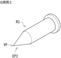
- FIG. 10 is a diagram illustrating a piston rod according to a third comparative example.
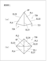
- FIG. 11 is a diagram illustrating a cutting edge portion of a piston rod according to the first modification.
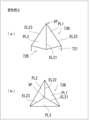
- FIG. 12 is a diagram illustrating a cutting edge portion of a piston rod according to the second modification.
- the perforator according to the present embodiment is used in a state in which a gas bottle is attached, and is a perforator for discharging gas from the gas bottle by opening a sealing plate that seals a gas outlet in the gas bottle when activated, a piston having a cutting edge portion at a tip end thereof, the cutting edge portion being disposed opposite the sealing plate when the perforator is attached to the gas bottle; a drive unit that, when actuated, propels the piston toward the sealing plate and causes the blade tip to pierce the sealing plate; Equipped with The cutting edge portion has a plurality of ridges and three or more piston blade surfaces separated from one another by the ridges.
- Fig. 1 is a diagram showing an example of the configuration of a perforator 1 according to an embodiment.
- the perforator 1 is used in a state where a cartridge-type gas bottle 2 (see Fig. 2) is attached, and is a perforator for discharging gas from the gas bottle by opening a sealing plate that seals a gas outlet in the gas bottle 2 when activated.
- a gas discharge device is constituted by a combination of the perforator 1 and the gas bottle 2 attached to the perforator 1.
- Fig. 1 shows the perforator 1 in a state before activation.
- Fig. 2 is a diagram showing an example of the configuration of the gas bottle 2 according to an embodiment.
- the gas bottle 2 is, for example, an iron cartridge container filled with gas at high pressure.
- the gas bottle 2 is formed with a gas outlet 21 for discharging gas. Furthermore, before use, the gas outlet 21 of the gas bottle 2 is sealed (blocked) by a sealing plate 22, thereby hermetically sealing the inside of the gas bottle 2.
- the sealing plate 22 is, for example, an iron circular plate that blocks the opening related to the gas outlet 21.
- the shape of the sealing plate 22 can be changed as appropriate to match the opening shape of the gas outlet 21.
- the gas bottle 2 can have the bottle-side attachment part 23 formed on the gas outlet 21 side connected to the body-side attachment part 16 formed on the perforator 1 side, allowing the gas bottle 2 to be detachably attached to the gas bottle 2.
- the body-side attachment part 16 of the perforator 1 has, for example, a recessed shape capable of receiving the bottle-side attachment part 23 of the gas bottle 2.
- the connection type between the bottle-side attachment part 23 and the body-side attachment part 16 is not particularly limited, but may be, for example, a screw connection method.
- the perforator 1 has a cylindrical first housing 10 and a second housing 40 as housings.
- the central axis extending in the axial direction of the first housing 10 and the second housing 40 is indicated by the symbol C1.
- the first housing 10 and the second housing 40 are arranged, for example, coaxially.
- the first housing 10 has a first end 11 located at one end in the axial direction which is an open end, to which a connection cap member 13 is attached.
- the above-mentioned main body side mounting portion 16 is formed by a recess formed on the inside of the connection cap member 13.
- the second end 12 located at the other end in the axial direction of the first housing 10 is an open end, to which a cylindrical second housing 40 is connected and fixed.
- the first end 41 located at one end of the second housing 40 in the axial direction, is fitted into the second end 12 of the first housing 10, and the two components are integrated to prevent them from falling off.
- a cylindrical piston guide 18 is disposed inside the first housing 10. The piston guide 18 is fixed to the inner wall surface of the first housing 10.
- An opening 14 is formed at the axial center position of the first housing 10, and a cylindrical gas discharge member 15 is connected and fixed to this opening 14.
- the gas discharge member 15 may be, for example, a threaded pipe joint member called a nipple.
- Symbol C2 shown in FIG. 1 indicates the central axis of the gas discharge member 15.
- the central axis C2 of the gas discharge member 15 extends in a direction perpendicular to the central axis C1 of the first housing 10.
- the first end 15A of the gas discharge member 15 is connected to the opening 14 of the first housing 10.
- the second end 15B which is located on the opposite side of the first end 15A in the axial direction of the gas discharge member 15, is connected to a gas pipe leading to a gas supply target (e.g., an airbag) to which the gas discharge device (perforator 1) supplies gas.
- a gas supply target e.g., an airbag
- a hollow gas flow passage 17 is formed inside the gas exhaust member 15, penetrating the gas exhaust member 15 along the axial direction, and the gas exhausted from the gas outlet 21 of the gas bottle 2 is supplied to a gas supply target through the gas flow passage 17 of the gas exhaust member 15.
- the airbag described above is an example of a gas supply target, and the gas supply target is not particularly limited.
- the internal structure of the housings (first housing 10, second housing 40) in the perforator 1 will be described in detail.
- the first end 41 side in the axial direction of the second housing 40 will be described as the front end side
- the second end 42 side located on the opposite side will be described as the rear end side.
- An initiator 50 as a drive unit is fixed to the second end 42 side (rear end side) of the second housing 40.
- the initiator 50 is, for example, an electric igniter.
- the initiator 50 has an ignition unit 51 arranged so as to face the storage space formed in the second housing 40.
- the ignition unit 51 is, for example, configured as a cup container that contains an ignition charge inside.
- the ignition charge is contained in the cup container in the ignition unit 51 in a state of contact with a bridge wire (resistor) that is connected so as to connect the base ends of a pair of conductive pins.
- a bridge wire resistor
- Examples of ignition charges that may be used include ZPP (zirconium potassium perchlorate), ZWPP (zirconium tungsten potassium perchlorate), THPP (titanium hydride potassium perchlorate), and lead tricinate.
- Reference numeral 52 denotes a lead wire, through which an operating current for operating the initiator 50 is supplied from a power source.
- the bridge wire in the ignition section 51 heats up, causing the ignition charge in the cup container to ignite and burn, generating combustion gas.
- the pressure inside the cup container rises, causing the cleavage surface 51A of the cup container to cleave, and the combustion gas is released into the storage space formed in the second housing 40.
- a first piston 60 and a second piston 70 are arranged from a position close to the initiator 50.
- the first piston 60 is arranged to be movable in the first piston movement space S1 formed inside the second housing 40 along the axial direction of the first piston movement space S1 (i.e., along the central axis C1).
- the first piston 60 is a roughly cylindrical piston member, and its outer diameter is equal to the inner diameter of the first guide surface 43 formed by the inner peripheral surface of the second housing 40.
- the rear end of the first piston 60 is provided with a recessed portion 61 where the rear end surface is recessed.
- the second piston 70 has a piston head 71 and a piston rod 72 extending forward from the piston head 71.
- the piston head 71 and piston rod 72 of the second piston 70 have a cylindrical shape, and the piston rod 72 has a smaller diameter than the piston head 71.
- the piston rod 72 is coaxial with and integrally connected to the piston head 71.
- the first piston 60 has a larger diameter than the piston head 71 of the second piston 70.
- the piston rod 72 of the second piston 70 has a cutting edge portion 73 on the tip side.
- a second piston movement space S2 is formed inside the piston guide 18, in which the second piston 70 can move.
- the second piston 70 can move along the axial direction of the second piston movement space S2 (i.e., along the central axis C1).
- the piston guide 18 has a small diameter inner circumferential surface 181 with a relatively small inner diameter, and a large diameter inner circumferential surface 182 with an inner diameter larger than that of the small diameter inner circumferential surface 181.
- the small diameter inner circumferential surface 181 is disposed on the front end side of the piston guide 18, and the large diameter inner circumferential surface 182 is disposed behind the small diameter inner circumferential surface 181.
- the inner diameter of the large diameter inner circumferential surface 182 is equal to the diameter of the piston head 71 in the second piston 70.
- the inner diameter of the small diameter inner circumferential surface 181 is equal to the diameter of the piston rod 72 in the second piston 70.
- the second piston 70 is housed in the first piston movement space S1 so that the piston rod 72 is housed in the second piston movement space S2 and the piston head 71 faces the front end surface 62 of the first piston 60.
- the front end surface of the piston guide 18 is formed as a first stopper wall 183 that prevents the first piston 60 from slipping out forward when the perforator 1 is in operation.
- the wall surface that forms a step between the small diameter inner circumferential surface 181 and the large diameter inner circumferential surface 182 is configured as a second stopper wall 184 that prevents the piston head 71 of the second piston 70 from slipping out forward when the perforator 1 is in operation.
- the perforator 1 configured as described above is used with the bottle side attachment part 23 of the gas bottle 2 attached to the main body side attachment part 16.
- the first housing 10 and the second housing 40 may be made of a metal such as aluminum or iron.
- the first piston 60 may be made of a heat-resistant resin.
- the second piston 70 may be made of a metal such as stainless steel or iron.
- the connection cap member 13 and the piston guide 18 may be made of resin. Of course, these materials are merely examples.
- FIG. 3 is a diagram for explaining the operation of the perforator 1 according to the embodiment.
- Reference numeral 3 in the figure denotes a gas discharge device including the perforator 1 and the gas bottle 2 attached to the perforator 1.
- the positional relationship of the first piston 60 and the second piston 70 is as shown in FIG. 1. That is, the first piston 60 is disposed in the first piston movement space S1 formed in the second housing 40 with the recessed portion 61 facing the ignition portion 51 of the initiator 50.
- the second piston 70 is disposed in the second piston movement space S2 with the piston head 71 facing the front end surface 62 of the first piston 60 and the cutting edge portion 73 formed on the tip side facing the sealing plate 22 of the gas bottle 2.
- the piston head 71 of the second piston 70 is disposed in a state of abutting against the front end surface 62 of the first piston 60, for example.
- FIG. 3 shows the state at the moment when the initiator 50 is activated.
- the ignition charge in the cup container at the ignition section 51 ignites and burns, the cleavage surface 51A of the cup container cleaves, and the combustion gas is forcefully released into the first piston movement space S1.
- the first piston 60 which receives the pressure of this combustion gas in the recessed portion 61, is launched axially forward within the first piston movement space S1.
- the second piston 70 is also launched in the second piston movement space S2 in the same axial direction as the first piston 60.
- FIG. 3 shows the state in which the first piston 60 and the second piston 70 have been launched.
- the first piston 60 launched as described above stops when it collides with the first stopper wall 183.
- the second piston 70 stops when the piston head 71 collides with the second stopper wall 184.
- the cutting edge 73 formed on the tip side of the piston rod 72 of the second piston 70 collides with the sealing plate 22 of the gas bottle 2, and the cutting edge 73 pierces the sealing plate 22.
- FIG. 3 shows the situation in which gas is being discharged from the gas outlet 21 of the gas bottle 2.
- the second piston 70 is pushed back from inside the gas outlet 21 by the gas pressure flowing out from the gas outlet 21 of the gas bottle 2.
- the gas that has flowed out from the gas outlet 21 of the gas bottle 2 then flows into the gas flow path 17 formed in the gas discharge member 15 through the space S3 formed between the main body side mounting part 16 of the perforator 1 and the piston guide 18, and is supplied to the gas supply target such as an airbag.
- FIG. 4 is a diagram illustrating the detailed structure of the second piston 70 according to the embodiment.
- (a) shows a first side surface of the second piston 70.
- (b) shows a second side surface of the second piston 70.
- the symbol C3 shown in (a) is a central axis extending in the axial direction of the second piston 70 (piston rod 72).
- (b) shows a side surface when the second piston 70 is rotated 90° around the central axis C3 based on the first side surface shown in (a).
- (c) shows the front surface (front face) of the second piston 70.
- (d) is a perspective view of the second piston 70.
- the cutting edge portion 73 formed on the tip side of the second piston 70 has multiple ridges EL and three or more piston blade surfaces separated from each other by the ridges EL.
- the cutting edge portion 73 is configured to include six (six) piston blade surfaces PL1 to PL6 separated from each other by seven ridges (EL0, EL11 to EL16).
- EL0, EL11 to EL16 ridges
- the symbol EL0 is the tip ridge that forms the tip of the cutting edge portion 73.
- the tip ridge EL0 extends in a direction perpendicular to the central axis C3 of the piston rod 72 (cutting edge portion 73) (perpendicular to the axis).
- the tip ridge EL0 may extend in a diagonal direction to the central axis C3 of the piston rod 72 (cutting edge portion 73).
- the tip ridge EL0 is set so that the projected length L0 (hereinafter referred to as the "axial projected length") when the tip ridge EL0 is projected along the central axis C3 direction (axial direction) of the piston rod 72 is shorter than the diameter of the piston rod 72.
- FIG. 5 is a diagram explaining the axial projected length L0 of the tip ridge EL0.
- the tip ridge EL0 extends in a direction perpendicular to the axis of the piston rod 72, so the actual length L1 of the tip ridge EL0 and the axial projected length L0 are equal (FIG. 5(a)).
- the axial projection length L0 is smaller than the actual length L1 of the tip edge EL0.
- one end of the other ridges is connected to both ends of the tip ridge EL0.
- the other ridges here refer to ridges other than the tip ridge EL0.
- multiple other ridges may be connected to at least one end of the tip ridge EL0.
- one end of the diagonal ridges EL11, EL13, and EL15 is connected to the first end e1 of the tip ridge EL0.
- one end of the diagonal ridges EL12, EL14, and EL16 is connected to the second end e2 of the tip ridge EL0.
- the other end of the diagonal ridges EL11 to EL16 connected to either end e1 or e2 of the tip ridge EL0 extends to the side surface 721 of the piston rod 72.
- the diagonal ridges EL11 to EL16 can also be considered as ridges that gradually expand the diameter of the cutting edge 73 from the tip side (the tip ridge EL0 side) to the base side (the side opposite the tip ridge EL0) in the axial direction of the cutting edge 73.
- the symbol ⁇ 1 shown in FIG. 4(a) is the inclination angle of the diagonal ridge (EL12 in the illustrated example) relative to the tip ridge EL0.
- the cutting edge 73 of the piston rod 72 configured as described above is configured as a knife edge including a tip ridge EL0 located at the tip.
- the cutting edge 73 has three or more piston blade surfaces PL that are mutually separated by ridges (EL0, EL11 to EL16).
- Figure 6 is a diagram illustrating a piston rod R1 having a cutting edge portion EP1 according to Comparative Example 1.
- the piston rod R1 according to Comparative Example 1 shown in Figure 6 (a) has a so-called two-sided cutting edge portion EP1, and two piston blade surfaces PL'1, PL'2 are divided by a tip ridge line EL0' located at the tip.
- the tip ridge line EL0' dividing the two piston blade surfaces PL' is projected in the axial direction of the piston rod R1, the axial projection length L0' is equal to the diameter of the piston rod R1.
- FIG. 6B shows a schematic diagram of the state after the sealing plate 22 that sealed the gas outlet 21 of the gas bottle 2 is perforated by the cutting edge EP1 of the piston rod R1 according to the comparative example 1.
- the symbol OE is the edge of the gas outlet 21.
- (b) shows the state after the sealing plate 22 that blocked the opening portion formed inside the edge OE is perforated.
- the symbol 22'P1 is a remaining piece remaining after the sealing plate 22 is perforated.
- the symbol 22'P2 is a separated piece that is torn off and separated from the remaining piece 22'P1 of the sealing plate 22.
- the separation piece 22'P2 may be transported through the gas flow path 17 in the gas exhaust member 15 to, for example, an airbag as a gas supply target, which may cause problems such as damage to the airbag.
- the cutting edge 73 is configured to include a plurality of ridges EL and three or more piston blade surfaces PL that are mutually separated by the ridges EL.
- the axial projection length L0 of the tip ridge EL0 located at the tip of the cutting edge 73 is smaller than the diameter of the piston rod 72 (the maximum outer diameter of the cutting edge 73).
- the inner diameter of the edge OE at the gas outlet 21 of the gas bottle 2 i.e., the diameter of the piston rod 72 (the maximum outer diameter of the cutting edge 73) to be set to a dimension larger than the diameter of the sealing plate 22, and it becomes possible to pierce the sealing plate 22 by inserting only a part of the cutting edge 73 into the inside of the gas outlet 21 (see FIG. 7).
- the axial projection length L0 of the tip ridge EL0 at the cutting edge 73 can be set to a dimension smaller than the diameter of the sealing plate 22, and the diameter of the piston rod 72 (the maximum outer diameter of the cutting edge 73) can be set to a dimension larger than the diameter of the sealing plate 22.
- FIG. 7 is a diagram illustrating a state in which the sealing plate 22 of the gas bottle 2 is perforated by the cutting edge 73 of the piston rod 72 according to this embodiment.
- the symbol L2 is the insertion depth (hereinafter referred to as the "cutting edge insertion depth (length)”) when the cutting edge 73 of the piston rod 72, which is launched when the perforator 1 is activated, is inserted further back than the position of the sealing plate 22 (inner side of the gas bottle 2) when the piston rod 72 is launched when the perforator 1 is activated and the cutting edge 73 is perforated by the cutting edge 73.
- the cutting edge insertion depth length
- the cutting edge insertion depth L2 can be easily adjusted by adjusting the length of the tip ridge EL0 and the inclination angles of the diagonal ridges EL11 to EL16.
- FIG. 8 is a diagram comparing the perforation conditions of the sealing plate in the embodiment and Comparative Example 1. Comparative Example 1 is shown in the upper part, and the embodiment is shown in the lower part. Also, the symbol BL in the figure indicates the boundary position between the sealing plate 22 and the edge portion OE, i.e., the outer periphery position of the sealing plate 22.
- (a) shows the state when the cracking of the sealing plate 22 starts.
- (d) shows the state when the perforation of the sealing plate 22 is completed.
- (b) and (c) show the states between (a) and (d), that is, the states in the process in which the perforation of the sealing plate 22 gradually progresses. Note that the hatched areas in each figure are schematic representations of the openings formed in the sealing plate 22.
- the basic performance required for the perforator 1 includes an opening cross-sectional area ("required opening cross-sectional area") formed when the sealing plate 22 is perforated.
- the appropriate value of this required opening cross-sectional area can be obtained, for example, from the pressure (MPa/s) of the gas flowing out from the gas outlet 21 of the gas bottle 2 when the sealing plate 22 is perforated.
- a required value set for the gas pressure at the beginning of perforation is 4.5 (MPa/s)
- a required value set for the required opening cross-sectional area to satisfy this condition is 10 (mm 2 ).
- these required values are merely examples.
- Both the embodiment and Comparative Example 1 are similar in that the required opening cross-sectional area must be secured when the sealing plate 22 is perforated.
- the tear length when the sealing plate 22 is torn corresponds to the length of the leading edge EL0' (axial projection length L0') in Comparative Example 1, and corresponds to the length of the leading edge EL0 (axial projection length L0) in the embodiment.
- Comparative Example 1 in the process of transitioning from (b) to (c) to (d), the tearing of the sealing plate 22 progresses by the two piston blade surfaces PL'1 and PL'2 formed on both sides of the leading edge EL0'.
- the dashed line in the figure is the fold line FL of the folding piece along which the torn sealing plate 22 is folded into the inside of the gas bottle 2.
- the length of the fold line FL gradually decreases as the process of perforating the sealing plate 22 progresses from (b) to (c) to (d). Therefore, as described in FIG. 6, there is a risk that a part of the sealing plate 22 may be torn off as a separation piece 22'P2 during the process of perforating the sealing plate 22.
- the cutting edge portion 73 of the piston rod 72 has a tip edge EL0 at its tip, which is shorter than the diameter of the piston rod 72 (the maximum outer diameter of the cutting edge portion 73).
- the diagonal edges EL11 to EL16 extend radially toward the side surface 721 of the piston rod 72, and the cross-sectional area of the cutting edge portion 73 is gradually expanded from the tip side to the base side by the piston blade surfaces PL1 to PL6 defined by these diagonal edges EL11 to EL16.
- one end of multiple diagonal ridges gathers at each end e1, e2 of the tip ridge EL0, and the other end of each diagonal ridge is connected to the side surface 721 of the piston rod 72, making it easy to form a multifaceted cutting edge portion 73 with multiple piston blade surfaces PL.
- the cutting edge 73 of the piston rod 72 in this embodiment has three or more piston blade surfaces PL, so that the perforating force when perforating the sealing plate 22 when the perforator 1 is operated can be increased compared to Comparative Example 1, which has only two piston blade surfaces PL'.
- the length of the tip ridge EL0 can be made shorter than the diameter of the piston rod 72, so the collision energy required to split the sealing plate 22 can be made smaller than in Comparative Example 1. In other words, according to this embodiment, even if the firing energy when firing the piston rod 72 when the perforator 1 is operated is small, it is possible to preferably perforate the sealing plate 22.
- a piston rod R2 having a cutting edge portion EP2 including a single piston blade surface PL' as shown in FIG. 9 is also possible.
- the cutting edge portion EP2 of a single cut type as in Comparative Example 2 like the cutting edge portion EP1 of a two cut type as in Comparative Example 1, a part of the sealing plate 22 is likely to tear off during the process of drilling the sealing plate 22. Also, as shown in the lower part of FIG. 9, the cutting edge portion EP2 of Comparative Example 2 pushes through the sealing plate 22 by shearing, so there is a risk that the opening (gas flow path) formed by the sheared sealing plate 22 may be blocked.
- a comparative example 3 in which the cutting edge EP3 has a so-called conical shape is also possible.
- this comparative example 3 there is an advantage that the cutting edge insertion depth L2 of the cutting edge EP3 is easily adjusted when the perforator 1 is operated, but since the structure does not form a ridge on the blade surface, it is difficult to ensure sufficient perforation force of the sealing plate 22 when the perforator 1 is operated.
- the piston rod R3 may be pushed back by the pressure of the gas flowing out from inside the gas bottle 2, and there is a risk that an opening having a predetermined required opening cross-sectional area cannot be formed.
- the piston rod 72 according to this embodiment can avoid the inconvenience of comparative example 3.
- FIG. 11 is a diagram for explaining the cutting edge portion 73A of the piston rod 72A according to the modified example 1.
- (a) is a perspective view of the cutting edge portion 73A side of the piston rod 72A, and
- (b) is a front view thereof.
- the cutting edge portion 73A according to the modified example 1 is different from the cutting edge portion 73 described in FIG. 4 in that the tip edge line EL0 is not formed on the tip side, and the apex VP formed at the tip has a pointed pyramid shape.
- the cutting edge portion 73A has a plurality of ridgelines extending from the apex VP as a starting point.
- each of the plurality of ridgelines gathers at the apex VP, and the other end of each ridgeline extends to the side surface 721 of the piston rod 72A.
- the cutting edge portion 73A according to the modified example 1 shown in FIG. 11 has a quadrangular pyramid shape with a square base, and four oblique ridgelines EL21 to EL24 extend from the apex VP.
- the four piston blade surfaces PL1 to PL4 are divided by the ridge lines EL21 to EL24.
- FIG. 12 is a diagram illustrating the cutting edge 73B of the piston rod 72B according to the second modification.
- the cutting edge 73B according to the second modification has multiple ridges, one end of which meets at the apex VP, and the other end of each ridge extends to the side surface 721 of the piston rod 72A.
- the cutting edge 73B according to the second modification shown in FIG. 12 has a triangular pyramid shape with a triangular base, and three diagonal ridges EL31-EL33 extend from the apex VP. The ridges EL31-EL33 then divide the three piston blade surfaces PL1-PL3.
- the piston rods 72A and 72B having the cutting edge portions 73A and 73B according to the first and second modifications also have the same technical effect as the piston rod 72 having the cutting edge portion 73 described above. That is, the cutting edge portions 73A and 73B according to the first and second modifications have a cone shape, so that the cutting edge insertion depth L2 during operation of the perforator 1 can be easily adjusted.
- the cutting edge portions 73A and 73B are configured to include a plurality of ridges and three or more piston blade surfaces PL separated from each other by the ridges, so that the length of the fold line FL along which the sealing plate 22 is folded to the rear side during the perforation process of the sealing plate 22 is not shortened.
- the sealing plate 22 can be suitably prevented from being torn off during perforation of the sealing plate 22.
- ridges are formed at the boundaries between the piston blade surfaces, so that the perforation force (splitting force) when the sealing plate 22 is perforated (split) during operation of the perforator 1 is excellent.
Landscapes
- Engineering & Computer Science (AREA)
- Mechanical Engineering (AREA)
- General Engineering & Computer Science (AREA)
- Filling Or Discharging Of Gas Storage Vessels (AREA)
- Containers And Packaging Bodies Having A Special Means To Remove Contents (AREA)
Abstract
穿孔器は、当該穿孔器がガスボトルに装着された状態において封止板に対向配置される刃先部を先端側に有するピストンロッドと、作動時にピストンロッドを封止板に向かって発射させ、刃先部に封止板を穿孔させる駆動部と、を備え、刃先部は、複数の稜線と、各稜線によって相互に区分される3面以上のピストン刃面と、を有する。
Description
本発明は、ガスボトルからガスを排出させるための穿孔器およびガス排出装置に関する。
内部にガスを貯留するガスボトルを装着して用いられ、ガスボトルにおけるガス出口を封止する封止板を開口(開封)することによってガスボトルからガスを排出するための穿孔器が知られている(例えば、特許文献1などを参照)。
この種の穿孔器は、ガスボトルに装着された状態において、封止板に対向配置される刃先を先端側に有するピストン、作動時にピストンを封止板に向かって発射させる駆動部などを有する。
例えば、特許文献1には、側面視がV字状に尖ったV字形状を有する刃先部を先端側に有するピストンロッドを備えた穿孔器が開示されている。
しかしながら、従来の穿孔器においては、ピストンロッドの刃先部によって封止板を穿孔する際、刃先部によって封止板が千切れてしまう虞があった。
本開示の技術は、上記した実情に鑑みてなされたものであり、ガスボトルからガスを排出するための穿孔器において、ピストンロッドの刃先部によって封止板を穿孔する際、封止板が千切れてしまうことを抑制する技術を提供することを目的とする。
本開示は、以下の態様により上記課題を解決する。
すなわち、本開示に係る技術は、ガスボトルを装着した状態で用いられ、作動時に前記ガスボトルにおけるガス出口を封止する封止板を開口することによって前記ガスボトルからガスを排出するための穿孔器であって、
前記穿孔器が前記ガスボトルに装着された状態において前記封止板に対向配置される刃先部を先端側に有するピストンロッドと、
作動時に前記ピストンロッドを前記封止板に向かって発射させ、前記刃先部に前記封止板を穿孔させる駆動部と、
を備え、
前記刃先部は、複数の稜線と、各稜線によって相互に区分される3面以上のピストン刃面と、を有する。
すなわち、本開示に係る技術は、ガスボトルを装着した状態で用いられ、作動時に前記ガスボトルにおけるガス出口を封止する封止板を開口することによって前記ガスボトルからガスを排出するための穿孔器であって、
前記穿孔器が前記ガスボトルに装着された状態において前記封止板に対向配置される刃先部を先端側に有するピストンロッドと、
作動時に前記ピストンロッドを前記封止板に向かって発射させ、前記刃先部に前記封止板を穿孔させる駆動部と、
を備え、
前記刃先部は、複数の稜線と、各稜線によって相互に区分される3面以上のピストン刃面と、を有する。
また、前記刃先部は、当該刃先部の先端を形成する先端稜線を含み、前記先端稜線は、前記ピストンロッドの軸線方向に沿った投影長さが、当該ピストンロッドの直径よりも小さくてもよい。
また、前記先端稜線の両端に他の稜線の一端が接続されていてもよい。
また、前記他の稜線における他端が前記ピストンロッドの側面まで伸びていてもよい。
また、前記先端稜線の少なくとも一方の端部には、複数本の前記他の稜線が接続されていてもよい。
また、前記刃先部の先端に形成される頂点に複数本の前記稜線における一端が集まっており、各稜線の他端が前記ピストンロッドの側面まで伸びていてもよい。
また、本開示の技術は、上述までの何れかの穿孔器と、前記穿孔器に装着可能なガスボトルと、を備える、ガス排出装置であってもよい。
本開示によれば、ガスボトルからガスを排出するための穿孔器において、ピストンロッドの刃先部によって封止板を穿孔する際、封止板が千切れてしまうことを抑制する技術を提供できる。
以下に、図面を参照して本開示の実施形態に係る保護装置を説明する。なお、実施形態における各構成及びそれらの組み合わせ等は、一例であって、本開示の主旨から逸脱しない範囲内で、適宜、構成の付加、省略、置換、及びその他の変更が可能である。本開示は、実施形態によって限定されることはなく、特許請求の範囲によってのみ限定される。
本実施形態に係る穿孔器は、ガスボトルを装着した状態で用いられ、作動時にガスボトルにおけるガス出口を封止する封止板を開口することによってガスボトルからガスを排出するための穿孔器であって、
穿孔器がガスボトルに装着された状態において封止板に対向配置される刃先部を先端側に有するピストンと、
作動時にピストンを封止板に向かって発射させ、刃先部に封止板を穿孔させる駆動部と、
を備え、
前記刃先部は、複数の稜線と、各稜線によって相互に区分される3面以上のピストン刃面と、を有する。
穿孔器がガスボトルに装着された状態において封止板に対向配置される刃先部を先端側に有するピストンと、
作動時にピストンを封止板に向かって発射させ、刃先部に封止板を穿孔させる駆動部と、
を備え、
前記刃先部は、複数の稜線と、各稜線によって相互に区分される3面以上のピストン刃面と、を有する。
<実施形態>
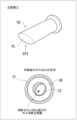
図1は、実施形態に係る穿孔器1の構成例を示す図である。穿孔器1は、カートリッジ式のガスボトル2(図2を参照)を装着した状態で用いられ、作動時に、ガスボトル2におけるガス出口を封止する封止板を開口することによってガスボトルからガスを排出するための穿孔器である。穿孔器1と、当該穿孔器1に装着されたガスボトル2との組み合わせによってガス排出装置が構成される。図1は、作動前の状態の穿孔器1を示している。また、図2は、実施形態に係るガスボトル2の構成例を示す図である。
図1は、実施形態に係る穿孔器1の構成例を示す図である。穿孔器1は、カートリッジ式のガスボトル2(図2を参照)を装着した状態で用いられ、作動時に、ガスボトル2におけるガス出口を封止する封止板を開口することによってガスボトルからガスを排出するための穿孔器である。穿孔器1と、当該穿孔器1に装着されたガスボトル2との組み合わせによってガス排出装置が構成される。図1は、作動前の状態の穿孔器1を示している。また、図2は、実施形態に係るガスボトル2の構成例を示す図である。
ガスボトル2は、例えば、内部にガスが高圧充填された鉄製のカートリッジ容器である。ガスボトル2は、ガスを排出するためのガス出口21が形成されている。また、使用前のガスボトル2において、ガス出口21が封止板22によって封止(閉塞)されており、これによってガスボトル2の内部が密閉されている。封止板22は、例えば、ガス出口21に係る開口を閉塞する鉄製の円板である。勿論、封止板22の形状は、ガス出口21の開口形状に合わせて適宜変更することができる。
ガスボトル2は、ガス出口21側に形成されるボトル側装着部23を、穿孔器1側に形成される本体側装着部16へとすることが可能であり、これによってガスボトル2をガスボトル2に着脱自在に装着することができる。穿孔器1の本体側装着部16は、例えば、ガスボトル2のボトル側装着部23を受け入れ可能な凹部形状を有している。また、ボトル側装着部23と本体側装着部16の接続形式は特に限定されないが、例えばネジ接続方式などが挙げられる。
穿孔器1は、ハウジングとして、筒状の第1ハウジング10および第2ハウジング40を有する。図1において、第1ハウジング10および第2ハウジング40の軸方向に伸びる中心軸を符号C1に示している。本実施形態において、第1ハウジング10および第2ハウジング40は、例えば同軸状に配置されている。
第1ハウジング10は、その軸方向における一端側に位置する第1端部11は開口端となっており、当該開口端には接続用キャップ部材13が取り付けられている。上述した本体側装着部16は、接続用キャップ部材13の内側に形成された凹部によって形成されている。また、第1ハウジング10の軸方向における他端側に位置する第2端部12は開口端となっており、当該開口端に筒状の第2ハウジング40が接続および固定されている。
第2ハウジング40の軸方向における一端側に位置する第1端部41は、第1ハウジング10の第2端部12に対して嵌合されており、双方の部材同士が脱落しないように一体となっている。また、第1ハウジング10の内側には、筒状のピストンガイド18が配設されている。ピストンガイド18は、第1ハウジング10の内壁面に固定されている。
第1ハウジング10の軸方向中間位置には、開口部14が形成されており、この開口部14には筒状のガス排出部材15が接続および固定されている。ガス排出部材15は、例えば、ニップルと呼ばれるねじ込み配管接手部材であってもよい。図1に示す符号C2は、ガス排出部材15の中心軸を示している。例えば、ガス排出部材15の中心軸C2は、第1ハウジング10の中心軸C1に対して直交方向に伸びている。ガス排出部材15は、第1端部15Aが第1ハウジング10の開口部14に接続されている。また、ガス排出部材15の軸方向において、第1端部15Aと反対側に位置する第2端部15Bには、ガス排出装置(穿孔器1)がガスを供給する対象であるガス供給対象(例えば、エアバッグ)に通じるガス配管などに接続される。ガス排出部材15の内側には、軸方向に沿って当該ガス排出部材15を貫通する中空状のガス流路17が形成されており、ガスボトル2のガス出口21から排出されるガスは、ガス排出部材15のガス流路17を通じてガス供給対象へと供給されるようになっている。なお、上記したエアバッグはガス供給対象の一例であり、ガス供給対象は特に限定されない。
次に、穿孔器1におけるハウジング(第1ハウジング10、第2ハウジング40)の内部構造について詳しく説明する。以下、第2ハウジング40の軸方向において、第1端部41側を前端側とし、その反対側に位置する第2端部42側を後端側として説明する。第2ハウジング40の第2端部42側(後端側)には、駆動部としてのイニシエータ50が固定されている。イニシエータ50は、例えば、電気式点火器である。イニシエータ50は、第2ハウジング40内に形成された収容空間を臨むようにして配置された点火部51を有している。点火部51は、例えば、点火薬を内部に収容するカップ容器形態として構成されている。例えば、点火薬は、一対の導電ピンの基端同士を連結するように連架されたブリッジワイヤ(抵抗体)に接触した状態で点火部51におけるカップ容器内に収容されている。点火薬としては、例えば、ZPP(ジルコニウム・過塩素酸カリウム)、ZWPP(ジルコニウム・タングステン・過塩素酸カリウム)、THPP(水素化チタン・過塩素酸カリウム)、鉛トリシネート等を採用しても良い。
符号52は、リードワイヤであり、イニシエータ50を作動するための作動電流が電力源からリードワイヤ52を通じて供給される。イニシエータ50に作動電流が供給されると、点火部51におけるブリッジワイヤが発熱する結果、カップ容器内の点火薬が着火、燃焼し、燃焼ガスが生成される。そして、カップ容器内における点火薬の燃焼に伴って当該カップ容器内の圧力が上昇し、カップ容器の開裂面51Aが開裂し、第2ハウジング40内に形成された収容空間へと燃焼ガスが放出される。
穿孔器1におけるハウジング(第1ハウジング10、第2ハウジング40)内に形成された収容空間には、イニシエータ50に近い位置から第1ピストン60、第2ピストン70が配置されている。第1ピストン60は、第2ハウジング40の内側に形成される第1ピストン移動空間S1内を、第1ピストン移動空間S1の軸方向に沿って(つまり、中心軸C1に沿って)移動可能に配置されている。例えば、第1ピストン60は概略円柱体のピストン部材であり、その外径は第2ハウジング40の内周面によって形成される第1ガイド面43の内径と等しい。また、第1ピストン60の後端部には、後端面が凹状に窪んだ窪み部61が設けられている。
第2ピストン70は、ピストンヘッド71と、ピストンヘッド71から前方に伸びるピストンロッド72を有している。第2ピストン70におけるピストンヘッド71およびピストンロッド72は円柱形状を有しており、ピストンロッド72はピストンヘッド71に比べて直径が小さい。ピストンロッド72は、ピストンヘッド71と同軸かつ一体に接続されている。なお、第1ピストン60は、第2ピストン70のピストンヘッド71よりも直径が大きい。また、第2ピストン70におけるピストンロッド72は、先端側に刃先部73を有している。
ピストンガイド18の内側には、第2ピストン70が移動可能とする第2ピストン移動空間S2が形成されている。第2ピストン70は、第2ピストン移動空間S2の軸方向に沿って(つまり、中心軸C1に沿って)移動可能である。ピストンガイド18は、相対的に内径が小さな小径内周面181と、当該小径内周面181よりも内径が大きい大径内周面182を有している。小径内周面181は、ピストンガイド18の前端側に配置され、大径内周面182は小径内周面181の後方に配置されている。大径内周面182の内径は、第2ピストン70におけるピストンヘッド71の直径と等しい。また、小径内周面181の内径は、第2ピストン70におけるピストンロッド72の直径と等しい。第2ピストン70は、第2ピストン移動空間S2にピストンロッド72が収容され、ピストンヘッド71が第1ピストン60の前端面62に対向するように第1ピストン移動空間S1に収容されている。
また、ピストンガイド18の前端面は、穿孔器1の作動時に第1ピストン60が前方へ抜け出すことを抑制する第1ストッパー壁183として形成されている。また、小径内周面181と大径内周面182との間に段差部を形成する壁面は、穿孔器1の作動時に第2ピストン70のピストンヘッド71が前方へ抜け出すことを抑制するための第2ストッパー壁184として構成されている。
上記のように構成される穿孔器1は、本体側装着部16にガスボトル2のボトル側装着部23を装着した状態で使用される。穿孔器1を構成する各部の材料は特に限定されないが、例えば、第1ハウジング10および第2ハウジング40は、アルミニウム、鉄などの金属製であってもよい。また、第1ピストン60は、耐熱性樹脂によって形成されていてもよい。第2ピストン70は、ステンレス、鉄などの金属製であってもよい。接続用キャップ部材13およびピストンガイド18は、樹脂製であってもよい。勿論、これらの材料は例示に過ぎない。
次に、穿孔器1の動作を説明する。図3は、実施形態に係る穿孔器1の動作を説明する図である。図中の符号3は、穿孔器1と、当該穿孔器1に装着されたガスボトル2とを含むガス排出装置である。穿孔器1の作動前における初期状態において、第1ピストン60および第2ピストン70の配置関係は図1に示す通りである。すなわち、第2ハウジング40内に形成された第1ピストン移動空間S1に第1ピストン60が、窪み部61をイニシエータ50の点火部51に対向させた状態で配置されている。そして、第2ピストン70は、ピストンヘッド71を第1ピストン60の前端面62に対向させ、先端側に形成された刃先部73をガスボトル2の封止板22に対向させた状態で第2ピストン移動空間S2に配置されている。第2ピストン70のピストンヘッド71は、例えば、第1ピストン60の前端面62に当接した状態で配置されている。
図3において、(a)は、イニシエータ50が作動した瞬間の状態を示している。イニシエータ50が作動すると、点火部51におけるカップ容器内の点火薬が着火および燃焼し、カップ容器の開裂面51Aが開裂して、燃焼ガスが第1ピストン移動空間S1へと勢い良く放出される。そして、この燃焼ガスの圧力を窪み部61で受けた第1ピストン60が、第1ピストン移動空間S1内を軸方向前方に向けて発射される。そして、第1ピストン60の軸方向前方への発射(高速移動)を受けて(第1ピストン60が第2ピストン70のピストンヘッド71に衝突して)、第2ピストン70も第2ピストン移動空間S2内を第1ピストン60と同軸方向に発射される。
図3において、(b)は、第1ピストン60および第2ピストン70が発射された状態を示している。上記のように発射された第1ピストン60は、第1ストッパー壁183に衝突することで停止する。また、第2ピストン70は、ピストンヘッド71が第2ストッパー壁184に衝突することで停止する。第2ピストン70が発射されると、その過程で、第2ピストン70におけるピストンロッド72の先端側に形成された刃先部73がガスボトル2の封止板22に衝突し、封止板22を刃先部73が穿孔する。
第2ピストン70におけるピストンロッド72の刃先部73が、ガスボトル2のガス出口21を封止する封止板22を穿孔すると、ボトル内に高圧充填されていたガス(図中、斜めハッチング付き矢印)がガス出口21から流出する。図3における(c)は、ガスボトル2のガス出口21からガスが排出されている状況を示している。ガスボトル2のガス出口21から流出するガス圧によって、第2ピストン70がガス出口21の内部から押し戻される。そして、ガスボトル2のガス出口21から流出したガスは、穿孔器1の本体側装着部16とピストンガイド18の間に形成される空間S3を通じて、ガス排出部材15内に形成されたガス流路17へと流入し、エアバッグなどのガス供給対象に供給される。
次に、穿孔器1における第2ピストン70の詳細について、刃先部73の構造を中心に説明する。図4は、実施形態に係る第2ピストン70の詳細構造を説明する図である。(a)は、第2ピストン70における第1の側面を示している。(b)は、第2ピストン70における第2の側面を示している。(a)に示す符号C3は、第2ピストン70(ピストンロッド72)の軸線方向に伸びる中心軸である。(b)は、(a)に示す第1の側面を基準として第2ピストン70を中心軸C3周りに90°回転させたときの側面を示している。(c)は、第2ピストン70の正面(前面)を示している。(d)は、第2ピストン70の斜視図である。
本実施形態において、第2ピストン70の先端側に形成される刃先部73は、複数の稜線ELと、各稜線ELによって相互に区分される3面以上のピストン刃面を有している。図4に示す例では、刃先部73は、7本の稜線(EL0、EL11~EL16)によって相互に区分される6つ(6面)のピストン刃面PL1~PL6を含んで構成されている。なお、各ピストン刃面PL1~PL6を区別しない場合には、「ピストン刃面PL」と表記する場合がある。
図中、符号EL0は、刃先部73の先端を形成する先端稜線である。図4に示す例では、先端稜線EL0は、ピストンロッド72(刃先部73)の中心軸C3に対して直交方向(軸線直交方向)に伸びている。但し、先端稜線EL0が、ピストンロッド72(刃先部73)の中心軸C3に対して斜め方向に伸びていてもよい。先端稜線EL0は、ピストンロッド72の中心軸C3方向(軸線方向)に沿って当該先端稜線EL0を投影したときの投影長さ(以下、「軸線方向投影長さ」という)L0が、当該ピストンロッド72の直径よりも短い寸法に設定されている。図5は、先端稜線EL0の軸線方向投影長さL0を説明する図である。図4で説明した態様では、先端稜線EL0がピストンロッド72の軸線直交方向に伸びているため、先端稜線EL0の実際の長さL1と軸線方向投影長さL0は等しい(図5の(a))。これに対して、先端稜線EL0が、ピストンロッド72の中心軸C3に対して斜め方向に延在している場合(図5の(b))、先端稜線EL0の実際の長さL1よりも軸線方向投影長さL0は小さくなる。
また、図4に示す刃先部73の構成例では、先端稜線EL0の両端に他の稜線の一端が接続されている。ここでいう他の稜線とは、先端稜線EL0以外の稜線を指す。その際、先端稜線EL0の少なくとも一方の端部には、複数本の他の稜線(以下、「斜め稜線」という)が接続されていてもよい。図4に示す例では、先端稜線EL0の第1端部e1に、斜め稜線EL11、EL13、EL15の一端が接続されている。また、先端稜線EL0の第2端部e2に、斜め稜線EL12、EL14、EL16の一端が接続されている。また、先端稜線EL0における何れかの端部e1、e2に接続される斜め稜線EL11~EL16の他端は、ピストンロッド72の側面721まで伸びている。斜め稜線EL11~EL16は、刃先部73の軸線方向における先端側(先端稜線EL0側)から基端側(先端稜線EL0と反対側)に向けて刃先部73を徐々に拡径させる稜線ということもできる。なお、図4の(a)に示す符号θ1は、先端稜線EL0に対する斜め稜線(図示の例ではEL12)の傾斜角度である。
以上のように構成されるピストンロッド72の刃先部73は、先端に配置される先端稜線EL0を含むナイフエッジ形態として構成されている。本実施形態における刃先部73は、稜線(EL0、EL11~EL16)によって相互に区分される3面以上のピストン刃面PLを有している。
図6は、比較例1に係る刃先部EP1を有するピストンロッドR1を説明する図である。図6の(a)に示す比較例1に係るピストンロッドR1は、いわゆる2面カットの刃先部EP1を有し、先端に配置される先端稜線EL0´によって2つのピストン刃面PL´1、PL´2が区分されている。このような比較例1においては、2つのピストン刃面PL´を区分する先端稜線EL0´をピストンロッドR1の軸線方向に投影したときの軸線方向投影長さL0´がピストンロッドR1の直径と等しくなる。このように、軸線方向投影長さL0´がピストンロッドR1の直径と等しい比較例1では、軸線方向投影長さL0´(ピストンロッドR1の直径)の寸法を、穿孔すべき封止板の直径と同じ、或いは、それよりも小さくする必要がある。そのため、このような比較例1においては、穿孔器1の作動時にピストンロッドR1が発射される際のストローク管理がシビアなものとなり、ガスボトル2のガス出口21にピストンロッドR1が深く挿入され過ぎた場合、刃先部EP1によって穿孔した封止板が千切れてしまう虞がある。図6の(b)には、比較例1に係るピストンロッドR1の刃先部EP1によってガスボトル2のガス出口21を封止していた封止板22を穿孔した後の状況を模式的に示している。符号OEは、ガス出口21の縁部である。(b)は、縁部OEの内側に形成された開口部分を閉塞していた封止板22が穿孔された後の状況を示している。符号22´P1は、封止板22を穿孔した後において残存している残存片である。また、符号22´P2は、封止板22の残存片22´P1から千切れて分離した分離片である。封止板22を穿孔した際に分離片22´P2が千切れてしまうと、当該分離片22´P2がガス排出部材15におけるガス流路17を通じて例えばガス供給対象としてのエアバッグに移送されてしまい、エアバッグを破損させるなどの不具合を招く虞がある。
これに対して、本実施形態に係るピストンロッド72においては、刃先部73が複数の稜線ELと、各稜線ELによって相互に区分される3面以上のピストン刃面PLを含んで構成されている。このような態様によれば、刃先部73の先端に位置する先端稜線EL0の軸線方向投影長さL0がピストンロッド72の直径(刃先部73の最大外径)よりも小さくなる。これによれば、ガスボトル2のガス出口21における縁部OEの内径、すなわち、封止板22の直径よりもピストンロッド72の直径(刃先部73の最大外径)を大きな寸法に設定することができ、刃先部73の一部だけをガス出口21の内部に挿入することによって封止板22を穿孔することが可能となる(図7を参照)。つまり、刃先部73における先端稜線EL0の軸線方向投影長さL0を封止板22の直径よりも小さな寸法に設定し、ピストンロッド72の直径(刃先部73の最大外径)を封止板22の直径よりも大きな寸法に設定することができる。
図7は、本実施形態に係るピストンロッド72の刃先部73によってガスボトル2の封止板22を穿孔した状況を例示する図である。符号L2は、穿孔器1の作動時に発射されるピストンロッド72が封止板22を刃先部73で穿孔する際、封止板22の位置よりも奥側(ガスボトル2の内部側)に刃先部73が挿入されるときの挿入深さ(以下、「刃先挿入深さ(長さ)という」)である。例えば、図7に示す例では、穿孔器1の作動時において、刃先部73の斜め稜線EL11、EL12がガス出口21における縁部OEに衝突した時点で、ガス出口21に向けて発射されたピストンロッド72の移動が停止される。本実施形態においては、先端稜線EL0の長さ、斜め稜線EL11~EL16の傾斜角度を調整することで、刃先挿入深さL2を容易に調整することができる。
図8は、実施形態と比較例1とにおける封止板の穿孔状況を対比する図である。上段に比較例1を示し、下段に実施形態を示す。また、図中の符号BLは、封止板22と縁部OEとの境界位置、すなわち封止板22の外周位置を示している。
(a)は、封止板22の開裂が開始された時点での状況を示している。(d)は、封止板22の穿孔が完了した状況を示している。(b)、(c)は、(a)から(d)までの間の各状況、すなわち封止板22の穿孔が徐々に進展している過程の各状況を示している。なお、各図のハッチング部分は、封止板22に形成された開孔部分を模式的に示したものである。
ここで、穿孔器1に対して要求される基本的な性能として、封止板22を穿孔した際に形成される開口断面積(「必要開口断面積」)が挙げられる。この必要開口断面積は、例えば、封止板22の穿孔時にガスボトル2のガス出口21から流出するガスの圧力(MPa/s)から適正値を求めることができる。例えば、穿孔初期のガス圧力に対して設定される要求値が4.5(MPa/s)であり、この条件を満たすための必要開口断面積に設定される要求値が10(mm2)とする例が挙げられる。勿論、これらの各要求値は例示である。実施形態と比較例1の何れにおいても、封止板22の穿孔時において必要開口断面積を確保する必要がある点では同様である。
図8の(a)において、封止板22が開裂するときの開裂長さは、比較例1においては、先端稜線EL0´の長さ(軸線方向投影長さL0´)に相当し、実施形態においては先端稜線EL0の長さ(軸線方向投影長さL0)に相当する。比較例1は、(b)→(c)→(d)と遷移する過程で、先端稜線EL0´の両側に形成された2つのピストン刃面PL´1、PL´2によって封止板22の開裂が進行する。そのため、封止板22の開裂は、先端稜線EL0´の延在方向と直交する方向(先端稜線直交方向)に沿って進行し、その開裂幅を徐々に増大させつつ最終的に(d)の穿孔完了状態に至る。図中の破線部分は、開裂した封止板22がガスボトル2の内部側に折り込まれる折り込み片の折り込み線FLである。図8に示すように、比較例1においては、封止板22の穿孔過程が(b)→(c)→(d)と進行するに従い、折り込み線FLの長さが徐々に減少する。そのため、図6で説明したように、封止板22の穿孔過程で、封止板22の一部が分離片22´P2として千切れてしまう虞がある。
一方、図8における下段に示すように、実施形態に係るピストンロッド72の刃先部73は、ピストンロッド72の直径(刃先部73の最大外径)よりも短い先端稜線EL0を先端に有している。そして、先端稜線EL0の端部e1,e2からは、斜め稜線EL11~EL16がピストンロッド72の側面721に向かって放射状に伸びており、これら斜め稜線EL11~EL16によって区画されるピストン刃面PL1~PL6によって刃先部73が先端側から基端側に向かって横断面積が徐々に拡大されている。これによれば、図8の下段に示すように、封止板22の穿孔過程が(b)→(c)→(d)と進行するに従って徐々に穿孔面積が拡大するが、比較例1とは逆に折り込み線FLの長さが徐々に長くなっていく。これは、ピストン刃面PLが2つしか有しない比較例1では実現できず、ピストン刃面PLを3面以上有する実施形態に係る刃先部73に特有の技術的特徴である。その結果、実施形態においては、(d)の穿孔完了状態に至るまで、封止板22が千切れてしまうことを好適に抑制できる。従って、封止板22の分離片22´P2がガス排出部材15におけるガス流路17を通じて例えばガス供給対象(エアバッグ)に移送されてしまうことを好適に抑制できる。
特に、実施形態におけるピストンロッド72の刃先部73によれば、先端稜線EL0の各端部e1、e2に複数本の斜め稜線における一端が集まっており、各斜め稜線の他端がピストンロッド72の側面721に接続されているため、多数のピストン刃面PLを有する多面カットの刃先部73を形成しやすい。
また、実施形態におけるピストンロッド72の刃先部73によれば、3面以上のピストン刃面PLを有しているため、ピストン刃面PL´を2面しか有しない比較例1に比べて、穿孔器1の作動時に封止板22を穿孔する際の穿孔力を増大させることができる。また、本実施形態によれば、ピストンロッド72の直径よりも先端稜線EL0の長さを短くすることができるため、封止板22の開裂に必要な衝突エネルギーも比較例1に比べて小さくすることが可能である。つまり、本実施形態によれば、穿孔器1の作動時にピストンロッド72を発射させる際の発射エネルギーが小さくても、封止板22を好適に穿孔することが可能となる。
なお、比較例2として、図9に示すような単一のピストン刃面PL´を含む刃先部EP2を有するピストンロッドR2も考えられる。比較例2に係るような一面カットタイプの刃先部EP2においては、比較例1のような2面カットタイプの刃先部EP1と同様、封止板22の穿孔過程で、封止板22の一部が千切れやすい。また、図9の下段に示すように、比較例2に係る刃先部EP2は剪断によって封止板22を押し切るため、剪断された封止板22が形成された開口(ガス流路)を閉塞してしまう虞もある。
また、図10に示すピストンロッドR3のように、刃先部EP3が所謂円錐形状を呈する比較例3も考えられる。このような比較例3においては、穿孔器1の作動時に刃先部EP3の刃先挿入深さL2を調整しやすいという利点はあるが、刃面に稜線が形成されない構造となっているため、穿孔器1の作動時における封止板22の穿孔力を十分に確保しにくい。そのため、穿孔器1の作動時に、刃先部EP3の頂点VPを起点として封止板22への穿孔が開始されたとしても、ガスボトル2の内部から流出するガスの圧力に負けてピストンロッドR3が押し戻されてしまい、所定の必要開口断面積を有する開口を形成できない虞があるが、本実施形態に係るピストンロッド72によれば比較例3のような不都合が起こることを回避できる。
<変形例>
次に、本実施形態に係るピストンロッド72の変形例について説明する。図11は、変形例1に係るピストンロッド72Aの刃先部73Aを説明する図である。(a)は、ピストンロッド72Aにおける刃先部73A側の斜視図であり、(b)はその正面図である。変形例1に係る刃先部73Aは、図4で説明した刃先部73とは異なり、先端側に先端稜線EL0が形成されておらず、先端に形成される頂点VPが尖った錐形状を有している。そして、刃先部73Aは、頂点VPを起点として複数本の稜線が伸びている。具体的には、複数本の稜線における一端が頂点VPに集まっており、各稜線の他端がピストンロッド72Aの側面721まで伸びている。図11に示す変形例1に係る刃先部73Aは、底形状が方形の四角錐形状を有しており、頂点VPから4本の斜め稜線EL21~EL24が伸びている。そして、各稜線EL21~EL24によって4つのピストン刃面PL1~PL4が区分されている。
次に、本実施形態に係るピストンロッド72の変形例について説明する。図11は、変形例1に係るピストンロッド72Aの刃先部73Aを説明する図である。(a)は、ピストンロッド72Aにおける刃先部73A側の斜視図であり、(b)はその正面図である。変形例1に係る刃先部73Aは、図4で説明した刃先部73とは異なり、先端側に先端稜線EL0が形成されておらず、先端に形成される頂点VPが尖った錐形状を有している。そして、刃先部73Aは、頂点VPを起点として複数本の稜線が伸びている。具体的には、複数本の稜線における一端が頂点VPに集まっており、各稜線の他端がピストンロッド72Aの側面721まで伸びている。図11に示す変形例1に係る刃先部73Aは、底形状が方形の四角錐形状を有しており、頂点VPから4本の斜め稜線EL21~EL24が伸びている。そして、各稜線EL21~EL24によって4つのピストン刃面PL1~PL4が区分されている。
図12は、変形例2に係るピストンロッド72Bの刃先部73Bを説明する図である。変形例2に係る刃先部73Bについても、変形例1と同様、複数本の稜線における一端が頂点VPに集まっており、各稜線の他端がピストンロッド72Aの側面721まで伸びている。図12に示す変形例2に係る刃先部73Bは、底形状が三角形の三角錐形状を有しており、頂点VPから3本の斜め稜線EL31~EL33が伸びている。そして、各稜線EL31~EL33によって3つのピストン刃面PL1~PL3が区分されている。
変形例1および変形例2に係る刃先部73A,73Bを有するピストンロッド72A,72Bにおいても、上述した刃先部73を有するピストンロッド72と同様の技術的効果を奏する。すなわち、変形例1および変形例2に係る刃先部73A,73Bにおいては、錐形状を有しているため、穿孔器1の作動時における刃先挿入深さL2を容易に調整することができる。そして、刃先部73A,73Bによれば、上述した刃先部73と同様、複数の稜線と、各稜線によって相互に区分される3面以上のピストン刃面PLを含んで構成されているため、封止板22の穿孔過程において、封止板22が奥側に折り込まれる折り込み線FLの長さが短くならない。その結果、封止板22の穿孔時に当該封止板22が千切れてしまうことを好適に抑制できる。また、上述した比較例3とは異なり、各ピストン刃面同士の境界部に稜線が形成されているため、穿孔器1の作動時に封止板22を穿孔(開裂)する際の穿孔力(開裂力)が優れている。
以上、本開示に係る実施形態について説明したが、本明細書に開示された各々の態様は、本明細書に開示された他のいかなる特徴とも組み合わせることができる。
1・・・穿孔器
2・・・ガスボトル
3・・・ガス排出装置
10・・・第1ハウジング
21・・・ガス出口
22・・・封止板
40・・・第2ハウジング
50・・・イニシエータ
60・・・第1ピストン
70・・・第2ピストン
71・・・ピストンヘッド
72・・・ピストンロッド
73・・・刃先部
2・・・ガスボトル
3・・・ガス排出装置
10・・・第1ハウジング
21・・・ガス出口
22・・・封止板
40・・・第2ハウジング
50・・・イニシエータ
60・・・第1ピストン
70・・・第2ピストン
71・・・ピストンヘッド
72・・・ピストンロッド
73・・・刃先部
Claims (7)
- ガスボトルを装着した状態で用いられ、作動時に前記ガスボトルにおけるガス出口を封止する封止板を開口することによって前記ガスボトルからガスを排出するための穿孔器であって、
前記穿孔器が前記ガスボトルに装着された状態において前記封止板に対向配置される刃先部を先端側に有するピストンロッドと、
作動時に前記ピストンロッドを前記封止板に向かって発射させ、前記刃先部に前記封止板を穿孔させる駆動部と、
を備え、
前記刃先部は、複数の稜線と、各稜線によって相互に区分される3面以上のピストン刃面と、を有する、
穿孔器。 - 前記刃先部は、当該刃先部の先端を形成する先端稜線を含み、
前記先端稜線は、前記ピストンロッドの軸線方向に沿った投影長さが、当該ピストンロッドの直径よりも小さい、
請求項1に記載の穿孔器。 - 前記先端稜線の両端に他の稜線の一端が接続されている、請求項2に記載の穿孔器。
- 前記他の稜線における他端が前記ピストンロッドの側面まで伸びている、請求項2に記載の穿孔器。
- 前記先端稜線の少なくとも一方の端部には、複数本の前記他の稜線が接続されている、請求項3に記載の穿孔器。
- 前記刃先部の先端に形成される頂点に複数本の前記稜線における一端が集まっており、各稜線の他端が前記ピストンロッドの側面まで伸びている、請求項5に記載の穿孔器。
- 請求項1から6の何れか一項に記載の穿孔器と、
前記穿孔器に装着可能なガスボトルと、
を備える、
ガス排出装置。
Applications Claiming Priority (2)
| Application Number | Priority Date | Filing Date | Title |
|---|---|---|---|
| JP2023-208062 | 2023-12-08 | ||
| JP2023208062A JP2025092279A (ja) | 2023-12-08 | 2023-12-08 | 穿孔器およびガス排出装置 |
Publications (1)
| Publication Number | Publication Date |
|---|---|
| WO2025120899A1 true WO2025120899A1 (ja) | 2025-06-12 |
Family
ID=95980749
Family Applications (1)
| Application Number | Title | Priority Date | Filing Date |
|---|---|---|---|
| PCT/JP2024/026458 Pending WO2025120899A1 (ja) | 2023-12-08 | 2024-07-24 | 穿孔器およびガス排出装置 |
Country Status (2)
| Country | Link |
|---|---|
| JP (1) | JP2025092279A (ja) |
| WO (1) | WO2025120899A1 (ja) |
Citations (3)
| Publication number | Priority date | Publication date | Assignee | Title |
|---|---|---|---|---|
| JPH06106255A (ja) * | 1991-09-19 | 1994-04-19 | Valeo Thermique Moteur | 円管壁に透孔を押し抜き加工する方法及びその方法により透孔をあけた円管 |
| JP2009006758A (ja) * | 2007-06-26 | 2009-01-15 | Toyoda Gosei Co Ltd | インフレータ |
| JP2015202754A (ja) * | 2014-04-14 | 2015-11-16 | 株式会社ダイセル | 穿孔器およびガス排出装置 |
-
2023
- 2023-12-08 JP JP2023208062A patent/JP2025092279A/ja active Pending
-
2024
- 2024-07-24 WO PCT/JP2024/026458 patent/WO2025120899A1/ja active Pending
Patent Citations (3)
| Publication number | Priority date | Publication date | Assignee | Title |
|---|---|---|---|---|
| JPH06106255A (ja) * | 1991-09-19 | 1994-04-19 | Valeo Thermique Moteur | 円管壁に透孔を押し抜き加工する方法及びその方法により透孔をあけた円管 |
| JP2009006758A (ja) * | 2007-06-26 | 2009-01-15 | Toyoda Gosei Co Ltd | インフレータ |
| JP2015202754A (ja) * | 2014-04-14 | 2015-11-16 | 株式会社ダイセル | 穿孔器およびガス排出装置 |
Also Published As
| Publication number | Publication date |
|---|---|
| JP2025092279A (ja) | 2025-06-19 |
Similar Documents
| Publication | Publication Date | Title |
|---|---|---|
| US11255147B2 (en) | Single use setting tool for actuating a tool in a wellbore | |
| US11578549B2 (en) | Single use setting tool for actuating a tool in a wellbore | |
| US20200362652A1 (en) | Single use setting tool for actuating a tool in a wellbore | |
| JP4719182B2 (ja) | 2パルスロケットモータ | |
| US12241326B2 (en) | Single use setting tool for actuating a tool in a wellbore | |
| CN106255625A (zh) | 充气机 | |
| ES2583303T3 (es) | Cartucho quebrantador de roca y cápsula de ignición | |
| US8136452B2 (en) | Gas generator | |
| WO2015182389A1 (ja) | ガス発生器 | |
| JP2002347567A (ja) | インフレータ | |
| JPH05147490A (ja) | 自動車用膨張安全システム | |
| CN105658485A (zh) | 气体发生器 | |
| CN110799384A (zh) | 气体发生器 | |
| JP2016203968A (ja) | ガス発生器 | |
| WO2025120899A1 (ja) | 穿孔器およびガス排出装置 | |
| US20240418486A1 (en) | Methods for delayed dispersion of chaff within countermeasure expendables | |
| CN106660511B (zh) | 带有可缩回活塞的点火器组件 | |
| KR20160074468A (ko) | 파열판 및 그것을 사용한 인플레이터 | |
| JP6095463B2 (ja) | ガス発生器 | |
| JP2000168487A (ja) | インフレ―タ | |
| CN107206961A (zh) | 气体发生器用的封闭构件的支撑结构及使用其的气体发生器 | |
| CN1046651C (zh) | 爆炸作业的工业器具炸药筒 | |
| JP7219193B2 (ja) | ガス発生器 | |
| JP7148318B2 (ja) | 貫通装置用の可変厚フライヤープレート | |
| SE506253C2 (sv) | Anordning vid bottenbricka |
Legal Events
| Date | Code | Title | Description |
|---|---|---|---|
| 121 | Ep: the epo has been informed by wipo that ep was designated in this application |
Ref document number: 24900198 Country of ref document: EP Kind code of ref document: A1 |