WO2025115769A1 - 熱硬化性樹脂組成物およびステータの製造方法 - Google Patents
熱硬化性樹脂組成物およびステータの製造方法 Download PDFInfo
- Publication number
- WO2025115769A1 WO2025115769A1 PCT/JP2024/041404 JP2024041404W WO2025115769A1 WO 2025115769 A1 WO2025115769 A1 WO 2025115769A1 JP 2024041404 W JP2024041404 W JP 2024041404W WO 2025115769 A1 WO2025115769 A1 WO 2025115769A1
- Authority
- WO
- WIPO (PCT)
- Prior art keywords
- resin composition
- die core
- stator
- resin
- slot
- Prior art date
- Legal status (The legal status is an assumption and is not a legal conclusion. Google has not performed a legal analysis and makes no representation as to the accuracy of the status listed.)
- Pending
Links
Images




Classifications
-
- H—ELECTRICITY
- H02—GENERATION; CONVERSION OR DISTRIBUTION OF ELECTRIC POWER
- H02K—DYNAMO-ELECTRIC MACHINES
- H02K15/00—Processes or apparatus specially adapted for manufacturing, assembling, maintaining or repairing of dynamo-electric machines
- H02K15/10—Applying solid insulation to windings, stators or rotors, e.g. applying insulating tapes
-
- H—ELECTRICITY
- H02—GENERATION; CONVERSION OR DISTRIBUTION OF ELECTRIC POWER
- H02K—DYNAMO-ELECTRIC MACHINES
- H02K3/00—Details of windings
- H02K3/30—Windings characterised by the insulating material
Definitions
- the present invention relates to a thermosetting resin composition and a stator. More specifically, the present invention relates to a thermosetting resin composition for use as a sealing material for a stator core, and a stator including the thermosetting resin composition as a sealing material.
- Patent Document 1 JP Patent Publication No. 2003-284277 describes a technology for using a resin material in a stator core.
- the document describes a rotating electric machine having a stator in which multiple coils are wound at regular intervals around a stator core made of multiple laminated electromagnetic steel sheets, a rotor that is rotatably held relative to the stator, and a cooling frame to which the stator is fixed, in which a highly heat-conductive composite material made of a thermosetting resin with an anisotropic structure in the resin component is arranged in the slots that form the winding portion of the stator. It is said that this configuration provides a rotating electric machine with good heat dissipation properties, as it easily transfers heat generated by the coils.
- a coil is inserted into the slot of a stator, and in order to ensure insulation between the coil and the slot, a resin layer may be formed on the wall of the slot before the coil is inserted.
- the process of forming this resin layer involves placing a die core (also called a blade) in the slot, filling the space formed by the slot wall and the die core with a resin composition, and then removing the die core after a certain period of time has passed.
- a die core also called a blade
- problems such as distortion of the resin composition around the die core can occur, making it impossible to increase the removal speed, and so a technology to address this problem was sought from the perspective of productivity.
- the present invention was developed in consideration of these circumstances, and aims to provide a technology that improves productivity when inserting a mold core into a slot and forming a resin layer on the wall surface of the slot.
- thermosetting resin composition used to fill a space formed between a blade, which is a die core inserted into a slot of a stator, and a wall surface of the slot to form an insulating layer comprising: Epoxy resin, A hardener; An inorganic filler; and a wax.
- the wax contains a higher fatty acid ester or a higher fatty acid amide, and the amount of the higher fatty acid ester or the higher fatty acid amide is 1.0 mass% or less based on the entire thermosetting resin composition.
- a method for manufacturing a stator comprising providing an insulating layer on a wall surface of a slot using the thermosetting resin composition according to ⁇ 1>, a core placement step of inserting a blade-shaped die core into the inside of the slot to form a filling space between a wall surface of the slot and the die core for filling the thermosetting resin composition; a resin filling step of filling the filling space with the thermosetting resin composition; A method for manufacturing a stator having the above structure.
- ⁇ 3> The method for manufacturing a stator according to ⁇ 2>, wherein the surface roughness Ra of the die core is 10 ⁇ m or less.
- ⁇ 4> The method for manufacturing a stator according to ⁇ 2> or ⁇ 3>, wherein a surface of the die core has a coating layer.
- ⁇ 5> The method for manufacturing a stator according to any one of ⁇ 2> to ⁇ 4>, further comprising, after the resin filling step, a die core removal step of pulling out and removing the die core.
- ⁇ 6> The method for manufacturing a stator according to claim 5, wherein in the die core removing step, a pulling force F when removing the die core is 250 kgf or less.
- ⁇ 7> The method for manufacturing a stator according to ⁇ 6>, wherein in the die core removal step, a ratio F/S of a surface area S of the die core to the pulling force F is 3.6 kgf/ cm2 or less.
- ⁇ 8> The method for manufacturing a stator according to any one of ⁇ 5> to ⁇ 7>, wherein the die core removing step is performed in an as-molded state.
- ⁇ 9> The method for manufacturing a stator according to any one of ⁇ 2> to ⁇ 8>, wherein the glass transition temperature Tg of the cured product of the thermosetting resin composition is 120° C. or higher.
- the present invention was developed in consideration of these circumstances, and provides a technology that improves productivity when inserting a mold core into a slot and forming a resin layer on the wall surface of the slot.
- FIG. 2 is a cross-sectional view taken along a direction perpendicular to the rotation axis of the motor.
- FIG. 2 is a vertical cross-sectional view of the motor in the direction of the rotation axis.
- FIG. 2 is an enlarged view of the periphery of a slot.
- FIG. 4 is a cross-sectional view showing the inside of a slot. 4 is a flowchart showing a method for manufacturing a stator.
- 11A to 11C are diagrams illustrating the transition of the state inside the slot during the resin layer forming process.
- 11A to 11C are diagrams illustrating the transition of the state inside the slot during the resin layer forming process.
- FIG. 2 is a diagram showing a stator simulation slot of the embodiment.
- FIG. 2 is a diagram showing a mold core of an embodiment.
- a technique for improving productivity is provided when a die core is inserted into a slot of a stator to form a resin layer on the wall surface of the slot.
- a wax (mold release agent) is contained in the thermosetting resin composition used to form the resin layer.
- the wax contains a higher fatty acid ester or a higher fatty acid amide, and the amount of the higher fatty acid ester or the higher fatty acid amide is set to 1.0 mass% or less with respect to the entire thermosetting resin composition.
- the surface of the blade-shaped die core used to form the resin layer is designed to be easily removable from the thermosetting resin composition. A specific description will be given below.
- the stator of this embodiment is applied to an electric motor (motor) as a rotating electric machine (electric motor, generator, or dual motor/generator). Hereinafter, an application of the motor will be described as one embodiment.
- Fig. 1 is a schematic cross-sectional view perpendicular to the rotational axis direction of motor 100.
- Fig. 2 is a schematic cross-sectional view in the rotational axis direction of motor 100.
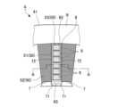
- Fig. 3 is an enlarged view of the periphery of the slot (area X in Fig. 1), and is a schematic cross-sectional view of a portion where coil 9 protrudes from the end of slot 8.
- Fig. 4 is a diagram showing the inside of slot 8, and is a cross-sectional view taken along line A-A in Fig. 3.
- the motor 100 comprises a case 1, a rotor 2 housed inside the case 1, a stator 4, and a coil 9.
- the case 1 includes a cylindrical portion 1a and side plate portions 1b and 1c that close both axial ends of the cylindrical portion 1a.
- the case 1 may be made of a material such as an aluminum alloy (cast metal casting), a resin material, or a combination thereof.
- ⁇ Rotor> As shown in Figures 1 and 2, the rotor 2 is housed inside the case 1. At the center of the rotor 2, a rotating shaft 3 is attached as an output shaft as shown in Figure 2. Both ends of the rotating shaft 3 are supported by the side plate portions 1b, 1c via bearings 3a. This allows the rotor 2 to rotate freely around the rotating shaft 3.
- Permanent magnets 5 are installed inside the rotor 2. Specifically, as shown in FIG. 1, multiple (eight in this case) permanent magnets 5 are arranged at equal intervals on the same circumference. At this time, the magnetic poles of adjacent permanent magnets 5 are set to be different from each other.
- the stator 4 has a stator core 41 and coils 9 sealed in the slots 8 .
- the stator core 41 is provided by stacking a plurality of electromagnetic steel sheets in the axial direction and closely fixing them together, and when viewed from the axial end as shown in Fig. 1, the stator core 41 is provided with a yoke portion 6 provided in an annular shape and a plurality of teeth portions 7 extending from the yoke portion 6 toward the rotor 2 side (inner circumference side).
- the plurality of teeth portions 7 are provided and arranged at equal intervals in the circumferential direction.
- 24 teeth portions 7 are provided.
- Slots 8 are provided between each of the teeth portions 7.
- the teeth portions 7 are also provided with a resin layer 50 that is thinly covered by wrapping a resin composition around the teeth portions 7.
- the coil 9 is a U-shaped rectangular wire wound so as to be housed in two spaced apart slots 8 across the teeth portion 7.
- the coil 9 may be housed in a liner member arranged in the slot 8 in a distributed winding manner, or may be housed without a liner member.
- the coil 9 has a coil body made of a good conductor such as copper and having a rectangular cross section, and a resin coating layer that coats the surface of the coil body.
- the resin coating layer may be made of the same material as that described below as the resin material of the resin layer 50.
- the teeth 7 are provided to correspond to the permanent magnets 5 of the rotor 2 described above, and by sequentially exciting each coil 9, the rotor 2 rotates due to attraction and repulsion between the corresponding permanent magnets 5.
- the teeth 7 are tapered, with a larger circumferential width on the outer periphery and a smaller width on the inner periphery. Teeth tips 71 are formed at the inner periphery end of the teeth 7, facing each other in the circumferential direction so as to reduce the width of the slot 8.
- the slots 8 are spaces between adjacent teeth 7, and are provided so that inner wall surfaces 72 of teeth 7 facing each other in the radial direction are parallel to each other, as shown in Figures 3 and 4.
- the space between the teeth tips 71 forms an inner peripheral opening of the slots 8.
- the slots 8 have a plurality of coils 9 arranged on the outer peripheral side (the yoke portion 6 side), a resin layer 50, and a resin sealing portion 65 filled in the space in the slots 8 excluding the coils 9 and the resin layer 50.
- resin layer 50 is integrally wrapped around the periphery of tooth portion 7 with a resin composition, and has a teeth inner surface resin layer 51 covering inner wall surface 72 of tooth portion 7, a teeth outer surface resin layer 52 covering upper surface 75a and lower surface 75b of tooth portion 7, and a yoke inner surface resin layer 53 covering inner wall surface 62 of yoke portion 6.
- the resin layer 50 is inserted into the stator 4, and more specifically, the multiple laminated electromagnetic steel sheets in the teeth 7 are tightly fixed together by wrapping the teeth 7 in a thin-walled manner. Note that the resin layer 50 does not necessarily have to wrap around the teeth 7 in a thin-walled manner, and the teeth outer surface resin layer 52 may be omitted.
- the presence of the teeth inner surface resin layer 51 and the yoke inner surface resin layer 53 ensures insulation between the coil 9 and the inner wall surface of the slot 8 (the inner wall surface 72 of the teeth 7 and the inner wall surface 62 of the yoke 6).
- the thickness of the resin layer 50 is, for example, 50 ⁇ m or more and 500 ⁇ m or less.
- the lower limit of the thickness is preferably 100 ⁇ m or more, and more preferably 150 ⁇ m or more.
- the upper limit of the thickness is preferably 400 ⁇ m or less, and more preferably 300 ⁇ m or less.
- the tooth inner surface resin layer 51, the tooth outer surface resin layer 52, and the yoke inner surface resin layer 53 may have the same thickness or different thicknesses.
- the lower limit of the thickness is in the above range from the viewpoint of ensuring the fluidity of the resin composition in the extremely narrow portion between the mold (mold core 80) and the wall surface of the slot 8 relative to the stator axial length (i.e., the thickness of the stator 4) during insert molding.
- the upper limit of the thickness is set within the above range from the standpoint of increasing the efficiency of space utilization within slot 8, allowing freedom in the size of coil 9 that can be used, and ensuring performance such as magnetic flux density.
- the physical properties of the cured product of the resin material constituting the resin layer 50 are, for example, as follows.
- the thermal conductivity of the cured resin material is 0.5 W/(m ⁇ K) or more.
- the lower limit of the thermal conductivity is preferably 1.0 W/(m ⁇ K) or more, and more preferably 2 W/(m ⁇ K) or more.
- the upper limit of the thermal conductivity is not particularly limited, but a practical value is 10 W/(m ⁇ K).
- the glass transition temperature Tg of the resin composition of the resin layer 50 is equal to or higher than 120° C., preferably equal to or higher than 140° C., and more preferably equal to or higher than 160° C. By setting the glass transition temperature Tg within the above range, the motor 100 can be used at high temperatures, and can be resistant to heat generation in the coil 9 and used at high output.
- the resin composition of the resin layer 50 will be specifically described below.
- the resin composition of the resin layer 50 preferably contains a thermosetting resin (A), a filler (B), and a curing agent (C) and the like.
- thermosetting resin (A) examples include epoxy resins, cyanate resins, polyimide resins, benzoxazine resins, unsaturated polyester resins, phenolic resins, melamine resins, silicone resins, bismaleimide resins, phenoxy resins, and acrylic resins.
- the thermosetting resin (A) one of these may be used alone, or two or more of them may be used in combination. Among them, from the viewpoint of high insulating properties, epoxy resin, phenol resin, and phenoxy resin are preferable as the thermosetting resin (A), and epoxy resin is particularly preferable from the viewpoint of ensuring flow in extremely narrow parts during molding.
- Epoxy resins include, for example, bisphenol type epoxy resins such as bisphenol A type epoxy resin, bisphenol F type epoxy resin, bisphenol E type epoxy resin, bisphenol S type epoxy resin, bisphenol M type epoxy resin (4,4'-(1,3-phenylenediisopridiene) bisphenol type epoxy resin), bisphenol P type epoxy resin (4,4'-(1,4-phenylenediisopridiene) bisphenol type epoxy resin), and bisphenol Z type epoxy resin (4,4'-cyclohexydiene bisphenol type epoxy resin); phenol novolac type epoxy resin, cresol novolac type epoxy resin, trisphenol group methane type novolac type epoxy resin, tetraphenol group epoxy resin, etc.
- bisphenol type epoxy resins such as bisphenol A type epoxy resin, bisphenol F type epoxy resin, bisphenol E type epoxy resin, bisphenol S type epoxy resin, bisphenol M type epoxy resin (4,4'-(1,3-phenylenediisopridiene) bisphenol type epoxy resin), bisphenol P type epoxy resin
- the epoxy resins include novolac epoxy resins such as tungsten-type novolac epoxy resins and novolac epoxy resins having a condensed ring aromatic hydrocarbon structure; biphenyl-type epoxy resins; aryl alkylene-type epoxy resins such as xylylene-type epoxy resins and biphenyl aralkyl-type epoxy resins; naphthalene-type epoxy resins such as naphthylene ether-type epoxy resins, naphthol-type epoxy resins, naphthalene diol-type epoxy resins, bifunctional to tetrafunctional epoxy naphthalene resins, binaphthyl-type epoxy resins, and naphthalene aralkyl-type epoxy resins; anthracene-type epoxy resins; phenoxy-type epoxy resins; dicyclopentadiene-type epoxy resins; norbornene-type epoxy resins; adamantane-type epoxy resins; and fluorene
- epoxy resins from the viewpoint of further improving heat resistance and insulation reliability, it is preferable to use one or more types selected from the group consisting of bisphenol type epoxy resins, novolac type epoxy resins, biphenyl type epoxy resins, aryl alkylene type epoxy resins, naphthalene type epoxy resins, anthracene type epoxy resins, and dicyclopentadiene type epoxy resins.
- phenolic resin examples include novolac-type phenolic resins such as phenol novolac resin, cresol novolac resin, and bisphenol A novolac resin, and resol-type phenolic resins, etc. One of these may be used alone, or two or more of them may be used in combination. Among the phenolic resins, phenolic novolac resins are preferred.
- the content of the thermosetting resin (A) is preferably 1% by mass or more, and more preferably 5% by mass or more, based on the total amount of the resin composition of the resin layer 50. On the other hand, the content is preferably 30% by mass or less, and more preferably 20% by mass or less, based on the total amount of the resin composition of the resin layer 50.
- thermosetting resin (A) When the content of thermosetting resin (A) is equal to or greater than the lower limit, the handleability of the entire resin composition of resin layer 50 is improved, making it easier to form the inner surface resin layer (teeth inner surface resin layer 51, yoke inner surface resin layer 53) and improving the strength of the inner surface resin layer (teeth inner surface resin layer 51, yoke inner surface resin layer 53).
- thermosetting resin (A) When the content of thermosetting resin (A) is equal to or less than the upper limit, the linear expansion coefficient and elastic modulus of the inner surface resin layer (teeth inner surface resin layer 51, yoke inner surface resin layer 53) are further improved, and the thermal conductivity is further improved.
- the filler (B) in this embodiment is used from the viewpoint of improving the thermal conductivity of the resin layer 50 (more specifically, the inner surface resin layer (tooth inner surface resin layer 51, yoke inner surface resin layer 53)) and obtaining strength.
- the filler (B) an inorganic filler is preferable, and a thermally conductive filler is particularly preferable. More specifically, from the viewpoint of achieving a balance between thermal conductivity and electrical insulation, examples of the filler (B) include silica, alumina, boron nitride, aluminum nitride, and silicon carbide. These may be used alone or in combination of two or more. Of these, it is preferable that the filler (B) is alumina or boron nitride.
- the content of the filler (B), i.e., the content of the above filler, is preferably 60 mass% or more based on the total amount of the resin composition.
- the resin composition preferably further contains a curing agent (C).
- a curing agent (C) one or more selected from the group consisting of a curing catalyst (C-1) and a phenol-based curing agent (C-2) can be used.
- Examples of the curing catalyst (C-1) include organic metal salts such as zinc naphthenate, cobalt naphthenate, tin octoate, cobalt octoate, bisacetylacetonate cobalt (II), and trisacetylacetonate cobalt (III); tertiary amines such as triethylamine, tributylamine, and 1,4-diazabicyclo[2.2.2]octane; 2-phenyl-4-methylimidazole, 2-ethyl-4-methylimidazole, 2,4-diethylimidazole, 2-phenyl-4-methyl-5-hydroxyimidazole, and the like.
- organic metal salts such as zinc naphthenate, cobalt naphthenate, tin octoate, cobalt octoate, bisacetylacetonate cobalt (II), and trisacetylacetonate cobalt (III
- Examples of the curing catalyst (C-1) include imidazoles such as midazole and 2-phenyl-4,5-dihydroxymethylimidazole; organic phosphorus compounds such as triphenylphosphine, tri-p-tolylphosphine, tetraphenylphosphonium tetraphenylborate, triphenylphosphine triphenylborane, and 1,2-bis-(diphenylphosphino)ethane; phenolic compounds such as phenol, bisphenol A, and nonylphenol; organic acids such as acetic acid, benzoic acid, salicylic acid, and p-toluenesulfonic acid; and mixtures thereof.
- the curing catalyst (C-1) one of these, including derivatives thereof, can be used alone, or two or more of these, including derivatives thereof, can be used in combination.
- the content of the curing catalyst (C-1) is not particularly limited, but is preferably 0.001% by mass or more and 1% by mass or less based on the total amount of the resin composition.
- examples of the phenol-based hardener (C-2) include novolac-type phenolic resins such as phenol novolac resin, cresol novolac resin, trisphenolmethane-type novolac resin, naphthol novolac resin, and aminotriazine novolac resin; modified phenolic resins such as terpene-modified phenolic resin and dicyclopentadiene-modified phenolic resin; aralkyl-type resins such as phenol aralkyl resins having a phenylene skeleton and/or biphenylene skeleton and naphthol aralkyl resins having a phenylene skeleton and/or biphenylene skeleton; bisphenol compounds such as bisphenol A and bisphenol F; and resol-type phenolic resins, and the like, which may be used alone or in combination of two or more kinds.
- novolac-type phenolic resins such as phenol novolac resin, cresol novolac resin, tri
- the phenol-based curing agent (C-2) is preferably a novolac-type phenol resin or a resol-type phenol resin.
- the content of the phenol-based curing agent (C-2) is not particularly limited, but is preferably 1% by mass or more, more preferably 5% by mass or more, based on the total amount of the resin composition, while the content is preferably 30% by mass or less, more preferably 15% by mass or less, based on the total amount of the resin composition.
- the resin composition may contain a coupling agent (D).
- the coupling agent (D) can improve the wettability at the interface between the thermosetting resin (A) and the filler (B).
- the coupling agent (D) is not particularly limited, but it is preferable to use, for example, one or more coupling agents selected from epoxy silane coupling agents, cationic silane coupling agents, amino silane coupling agents, titanate-based coupling agents, and silicone oil-type coupling agents.
- the content of the coupling agent (D) is not particularly limited, but is preferably 0.05% by mass or more, and more preferably 0.1% by mass or more, relative to 100% by mass of the filler (B). On the other hand, the content is preferably 3% by mass or less, and more preferably 2% by mass or less, relative to 100% by mass of the filler (B).
- the resin composition may contain a phenoxy resin (E).
- a phenoxy resin (E) By containing the phenoxy resin (E), the bending resistance of the resin layer 50 can be improved, and the elastic modulus can be reduced, so that the stress relaxation force of the resin layer 50 can be improved.
- the viscosity increases, reducing fluidity and preventing the occurrence of voids.
- the resin layer 50 is used in close contact with a metal member (i.e., the teeth portion 7 or the yoke portion 6), the adhesion between the metal and the hardened resin composition can be improved.
- phenoxy resin (E) examples include phenoxy resins having a bisphenol skeleton, phenoxy resins having a naphthalene skeleton, phenoxy resins having an anthracene skeleton, and phenoxy resins having a biphenyl skeleton, etc. Phenoxy resins having a structure having a plurality of these skeletons can also be used.
- the content of the phenoxy resin (E) is, for example, preferably 3 mass % or more and 10 mass % or less with respect to the total amount of the resin composition.
- the resin composition contains a wax. This can improve the releasability from the mold core 80 after molding.
- wax include natural waxes such as carnauba wax, synthetic waxes such as Montan acid ester wax and oxidized polyethylene wax, higher fatty acids such as zinc stearate and their metal salts, paraffin, and higher fatty acid amides. These may be used alone or in combination of two or more. It is preferable that the resin composition contains a higher fatty acid ester or a higher fatty acid amide, and it is particularly preferable that the resin composition contains Montan acid ester wax.
- Hydrocarbon waxes include paraffin waxes with 24 or more carbon atoms, olefin waxes with 26 or more carbon atoms, alkylbenzenes with 28 or more carbon atoms, and microcrystalline waxes.
- Higher fatty acids include higher saturated fatty acids with 12 or more carbon atoms, such as lauric acid, myristic acid, palmitic acid, stearic acid, arachidic acid, behenic acid, cerotic acid, and montanic acid, and unsaturated fatty acids with 18 or more carbon atoms, such as oleic acid, linoleic acid, linolenic acid, elaidic acid, octadecenoic acid, arachidonic acid, cadreic acid, erucic acid, and parinaric acid.
- higher saturated fatty acids with 12 or more carbon atoms such as lauric acid, myristic acid, palmitic acid, stearic acid, arachidic acid, behenic acid, cerotic acid, and montanic acid
- unsaturated fatty acids with 18 or more carbon atoms, such as oleic acid, linoleic acid, linolenic acid, elaidic acid, oct
- Waxes derived from higher fatty acids include higher fatty acid esters, higher fatty acid amides, and higher fatty acid salts (metal soaps), etc.
- the higher fatty acid esters are esters of the above higher fatty acids with monohydric or polyhydric alcohols.
- monohydric alcohols include capryl alcohol, lauryl alcohol, myristyl alcohol, palmityl alcohol, stearyl alcohol, and behenyl alcohol
- polyhydric alcohols include ethylene glycol, propylene glycol, butanediol, glycerin, pentaerythritol, and sorbitol.
- higher fatty acid amides include saturated higher fatty acid amides such as lauric acid amide, palmitic acid amide, stearic acid amide, and behenic acid amide; unsaturated higher fatty acid amides such as erucic acid amide, oleic acid amide, brassidic acid amide, and elaidic acid amide; and higher fatty acid bisamides such as methylene bisstearic acid amide, ethylene bisstearic acid amide, and ethylene bisoleic acid amide (including saturated or unsaturated higher fatty acid alkylamides such as higher fatty acid methylamides and higher fatty acid ethylamides).
- saturated higher fatty acid amides such as lauric acid amide, palmitic acid amide, stearic acid amide, and behenic acid amide
- unsaturated higher fatty acid amides such as erucic acid amide, oleic acid amide, brassidic acid amide, and ela
- wax wax release agent
- its content in the entire resin molding material is preferably 0.01 to 3 mass %, and more preferably 0.05 to 2 mass %. This ensures that the effect of improved mold releasability can be obtained. As a result, the molding precision of the inner resin layer of resin layer 50 (more specifically, teeth inner resin layer 51 and yoke inner resin layer 53) can be improved.
- the amount of the higher fatty acid ester or the higher fatty acid amide is 1.0 mass% or less based on the entire thermosetting resin composition.
- the upper limit of the amount of the higher fatty acid ester or the higher fatty acid amide is preferably 0.8 mass% or less, more preferably 0.6 mass% or less.
- the lower limit is, for example, 0.1 mass% or more, preferably 0.2 mass% or more, and more preferably 0.3 mass% or more.
- the resin composition may further contain an antioxidant, a leveling agent, etc., within the scope of not impairing the effects of the present invention.
- the resin sealing portion 65 is provided inside the slot 8 (more specifically, between the resin layer 50 and the coil 9) to seal the coil 9.
- the resin sealing portion 65 may be provided by insert molding, or may be provided as a separate component.
- the resin material used for the resin sealing portion 65 may be the same as that described for the resin layer 50.
- a stator 4 is prepared by laminating a plurality of electromagnetic steel plates in the axial direction and closely fixing them together (stator preparation step S10).
- a mold core 80 is placed in the slot 8, and the periphery of the teeth portion 7 (the inner wall surface 72, the upper surface 75a, and the lower surface 75b) and the inner wall surface 62 of the yoke portion 6 are integrally covered with an insulating resin composition by insert molding to form a resin layer 50 (resin layer forming process S20).
- the resin layer forming process S20 will be described in detail later.
- coil placement process S30 the inner peripheral area of the slot 8 is filled with a resin material to obtain a resin sealed portion 65 (coil sealing process S40).
- Figures 6 and 7 show the transition of the state inside the slot during the resin layer forming process S20, with Figure 6 being a cross-sectional view cut along a plane perpendicular to the axis, and Figure 7 being a cross-sectional view of a portion corresponding to the A-A section in Figure 3.
- the resin layer formation process S20 includes a core placement process S21, a resin filling process S22, and a mold core removal process S23.
- the core placement process S21 is a process of inserting a blade-shaped mold core 80 into the inside of the slot 8.
- the mold core 80 is inserted into the inside of the slot 8 from the upper side as shown in the figure.
- the upper and lower ends of the mold core 80 protrude from the upper and lower ends of the slot 8.
- the core placement process S21 forms a space 88 between the wall surface of the slot 8 (the inner wall surface 72 of the teeth portion 7 and the inner wall surface 62 of the yoke portion 6) and the mold core 80 for filling with a thermosetting resin composition.
- the resin filling step S22 is a step of filling the space 88 formed by the core placement step S21 with the above-mentioned thermosetting resin composition.
- the mold core removal process S23 is a process that follows the resin filling process S22 and involves pulling out and removing the mold core 80. This process is carried out in the as-molded state, where no after-curing has been performed.
- an opening 87 for operation is provided near the upper end 80a of the mold core 80.
- a specified jig is attached to this opening 87, and the mold core 80 is pulled out in the upward direction as shown.
- a resin layer 50 is formed on the wall surfaces of the slot 8 (the inner wall surfaces 72 of the teeth portion 7 and the inner wall surfaces 62 of the yoke portion 6) as shown in Figures 6(d) and 7(d).
- the mold core 80 used in the resin layer forming step S20 will be described.
- the die core 80 is provided in an appropriate shape depending on the shape of the slot 8 and the resin layer 50 to be formed, but generally has a long, thin blade shape.
- the die core 80 can be made of a general die steel material, for example, SKD-11 (JIS standard).
- the surface of the die core 80 (the surface that comes into contact with the resin layer 50) is smoothed. This makes it possible to avoid any effect such as distortion on the resin layer 50 when the die core 80 is pulled out.
- the water contact angle of the surface of the mold core 80 is 90° or more, preferably 95° or more, and more preferably 100° or more.
- the upper limit of the water contact angle is a realistic value of 170° or less, preferably 160° or less, and more preferably 150° or less.
- the water contact angle is measured in accordance with JIS R3257, and can be measured, for example, using a contact angle meter.
- known methods such as the width-height method ( ⁇ /2 method), the Young-Laplace method, and the ellipse method can be used.
- the surface roughness Ra of the die core 80 is 10 ⁇ m or less, preferably 5 ⁇ m or less, and more preferably 1 ⁇ m or less. There is no particular lower limit to the surface roughness Ra, but the practical range is 0.01 ⁇ m or more, preferably 0.05 ⁇ m or more, and more preferably 0.1 ⁇ m or more.
- the surface roughness Ra is measured in accordance with JIS B 0601-2001.
- the pulling force F of the die core 80 and the ratio F/S1 of the surface area S1 to the pulling force F can be suppressed, and defects such as distortion of the resin layer 50 can be prevented.
- These can be achieved by setting the material of the resin layer 50 (particularly the selection and amount of wax) and the surface condition of the die core 80 (water contact angle and surface roughness Ra) as described above.
- thermosetting resin composition used to fill a space 88 formed between a die core 80 (blade) inserted into a slot 8 of a stator 4 and a wall surface of the slot 8 (an inner wall surface 72 of a tooth portion 7 and an inner wall surface 62 of a yoke portion 6) to form an insulating layer, Epoxy resin, A hardener; An inorganic filler; and wax (release agent),
- the wax contains a higher fatty acid ester or a higher fatty acid amide, and the amount of the higher fatty acid ester or the higher fatty acid amide is 1.0 mass% or less based on the entire thermosetting resin composition.
- a method for manufacturing a stator 4 comprising providing an insulating layer (resin layer 50) on a wall surface of a slot 8 (an inner wall surface 72 of a tooth portion 7 and an inner wall surface 62 of a yoke portion 6) using the thermosetting resin composition according to ⁇ 1>, A core placement step S21 of inserting a blade-shaped die core 80 into the inside of the slot 8 to form a filling space (space 88) for filling the thermosetting resin composition between the wall surface of the slot 8 and the die core 80; a resin filling step S22 of filling the filling space (space 88) with the thermosetting resin composition; A method for manufacturing a stator having the structure.
- ⁇ 3> The method for manufacturing a stator 4 according to ⁇ 2>, wherein the surface roughness Ra of the die core 80 is 10 ⁇ m or less.
- ⁇ 4> The method for manufacturing a stator according to ⁇ 2> or ⁇ 3>, wherein a surface of the die core 80 has a coating layer.
- ⁇ 5> The method for manufacturing a stator 4 according to any one of ⁇ 2> to ⁇ 4>, further comprising a die core removal step S23 of pulling out and removing the die core 80 after the resin filling step S22.
- ⁇ 6> The method for manufacturing a stator 4 according to ⁇ 5>, wherein in the die core removal step S23, a pulling force F when removing the die core 80 is 250 kgf or less.
- ⁇ 7> The method for manufacturing a stator 4 according to ⁇ 6>, wherein in the die core removal step S23, a ratio F/S1 of a surface area S1 of the die core 80 to the pulling force F is 3.6 kgf/ cm2 or less.
- ⁇ 8> The method for manufacturing a stator 4 according to any one of ⁇ 5> to ⁇ 7>, wherein the die core removing step S23 is performed in an as-molded state.
- ⁇ 9> The method for manufacturing a stator 4 according to any one of ⁇ 2> to ⁇ 8>, wherein a glass transition temperature Tg of a cured product of the thermosetting resin composition is 120° C. or higher.
- thermosetting resin composition corresponding to the resin layer 50 of the embodiment is exemplified.
- the raw material components used in Example 1 and Comparative Example 1 are shown below.
- Inorganic filler Inorganic filler 1: Fused spherical alumina (Micron Co., Ltd., average particle size 20 ⁇ m) Inorganic filler 2: Fused spherical silica (Tokuyama Corporation, average particle size 0.2 ⁇ m) Inorganic filler 3: Fused spherical alumina (manufactured by Admatechs Co., Ltd., average particle size 0.6 ⁇ m)
- Colorant 1 Carbon black
- Coupling material Coupling material 1: N-phenyl-3-aminopropyltrimethoxysilane Coupling material 2: 3-mercaptopropyltrimethoxysilane
- Epoxy resin 1 Biphenyl type epoxy resin (manufactured by Mitsubishi Chemical Corporation, YX4000HK)
- Epoxy resin 2 Triphenolmethane type phenolic resin (manufactured by Mitsubishi Chemical Corporation, YL6677)
- Hardener 1 Novolac-type phenol compound (manufactured by Sumitomo Bakelite Co., Ltd.)
- Cure Accelerator Tetraphenylphosphonium 4,4'-sulfonyldiphenolate
- Cure accelerator 2 Tetraphenylphosphonium bis(naphthalene-2,3-dioxy)phenylsilicate
- Wax (release agent)) Wax 1 Carnauba wax (manufactured by Air Water Inc.) Wax 2: Montanic acid derivative (Clariant Japan Co., Ltd., Licowax E) Wax 3: Diethanolamine dimontanic acid ester
- Ion Scavenger 1 Hydrotalcite (Kyowa Chemical Industry Co., Ltd.)
- Triazole compound 1 Triazole compound (manufactured by Shikoku Chemical Industry Co., Ltd.)
- Silicone resin Silicone oil (KR-480, manufactured by Shin-Etsu Chemical Co., Ltd.) Silicone resin: Epoxy polyether modified silicone oil (FZ-3730, manufactured by Dow Corning Toray Co., Ltd.)
- Glass transition temperature Tg Glass transition temperature of the cured product of the obtained resin composition was measured as follows. First, the encapsulating resin composition was injected and molded using a transfer molding machine at a mold temperature of 175°C, an injection pressure of 9.8 MPa, and a curing time of 5 minutes to obtain a test piece of 15 mm x 3 mm x 4 mm. Next, using a thermomechanical analyzer (Seiko Denshi Kogyo Co., Ltd., TMA100), measurements were performed under the conditions of a measurement temperature range of 40°C to 300°C and a temperature rise rate of 5°C/min. From the measurement results, the glass transition temperature was calculated.
- TMA100 thermomechanical analyzer
- Thermal Conductivity The resin composition obtained in each example was injected and molded into an encapsulating resin composition using a transfer molding machine at a mold temperature of 175°C, an injection pressure of 9.8 MPa, and a curing time of 3 minutes to obtain a cured body measuring 10 mm x 10 mm x 1 mm.
- the thermal conductivity of the resulting cured product was calculated using the following formula from the thermal diffusion coefficient ( ⁇ ) measured by the laser flash method (half-time method), the specific heat (Cp) measured by the DSC method, and the density ( ⁇ ) measured in accordance with JIS K 6911.
- the unit of thermal conductivity is W/m ⁇ K.
- Thermal conductivity [W/m ⁇ K] ⁇ [mm 2 /s] ⁇ Cp [J/kg ⁇ K] ⁇ ⁇ [g/cm 3 ]
- (stator simulation type) 8 shows the shape of the slots in the stator simulation mold used to measure the pull-out force F and the pull-out force F/surface area S. Here, one slot is shown.
- the dimensions of the slots were as follows: Slot width (L1): 4.5 mm Slot length (L2): 24.3 mm Slot height: 150mm
- FIG. 9(a) is a plan view
- Figure 9(b) is a side view
- Figure 9(c) is a front view.
- the blackened area in the figure is the area that will become the blade pressure-receiving area (surface area S).
- the dimensions corresponding to the blade pressure receiving area of the mold core 80 (blade) were as follows: Blade pressure width (L3): 3.9 mm Blade pressure length (L4): 20.5 mm Blade pressure height (L5): 156 mm
- the die cores 80 used in Examples 3 to 5 had the same shape but different surface conditions.
- ⁇ Surface roughness Ra> The surface roughness Ra of the die core 80 was measured using a measuring device (manufactured by KEYENCE Corporation) in accordance with JIS B 0601-2001.
Landscapes
- Engineering & Computer Science (AREA)
- Power Engineering (AREA)
- Manufacturing & Machinery (AREA)
- Manufacture Of Motors, Generators (AREA)
Priority Applications (1)
| Application Number | Priority Date | Filing Date | Title |
|---|---|---|---|
| JP2025521099A JPWO2025115769A1 (https=) | 2023-12-01 | 2024-11-22 |
Applications Claiming Priority (2)
| Application Number | Priority Date | Filing Date | Title |
|---|---|---|---|
| JP2023203627 | 2023-12-01 | ||
| JP2023-203627 | 2023-12-01 |
Publications (1)
| Publication Number | Publication Date |
|---|---|
| WO2025115769A1 true WO2025115769A1 (ja) | 2025-06-05 |
Family
ID=95897870
Family Applications (1)
| Application Number | Title | Priority Date | Filing Date |
|---|---|---|---|
| PCT/JP2024/041404 Pending WO2025115769A1 (ja) | 2023-12-01 | 2024-11-22 | 熱硬化性樹脂組成物およびステータの製造方法 |
Country Status (2)
| Country | Link |
|---|---|
| JP (1) | JPWO2025115769A1 (https=) |
| WO (1) | WO2025115769A1 (https=) |
Citations (3)
| Publication number | Priority date | Publication date | Assignee | Title |
|---|---|---|---|---|
| JPS59159913U (ja) * | 1983-04-12 | 1984-10-26 | 株式会社東芝 | 屋外用モ−ルド形変圧器 |
| WO2022124329A1 (ja) * | 2020-12-09 | 2022-06-16 | 住友ベークライト株式会社 | ステータ、回転電機およびステータの製造方法 |
| JP7375984B2 (ja) * | 2021-11-08 | 2023-11-08 | 住友ベークライト株式会社 | 金型及び樹脂層形成方法 |
-
2024
- 2024-11-22 WO PCT/JP2024/041404 patent/WO2025115769A1/ja active Pending
- 2024-11-22 JP JP2025521099A patent/JPWO2025115769A1/ja active Pending
Patent Citations (3)
| Publication number | Priority date | Publication date | Assignee | Title |
|---|---|---|---|---|
| JPS59159913U (ja) * | 1983-04-12 | 1984-10-26 | 株式会社東芝 | 屋外用モ−ルド形変圧器 |
| WO2022124329A1 (ja) * | 2020-12-09 | 2022-06-16 | 住友ベークライト株式会社 | ステータ、回転電機およびステータの製造方法 |
| JP7375984B2 (ja) * | 2021-11-08 | 2023-11-08 | 住友ベークライト株式会社 | 金型及び樹脂層形成方法 |
Also Published As
| Publication number | Publication date |
|---|---|
| JPWO2025115769A1 (https=) | 2025-06-05 |
Similar Documents
| Publication | Publication Date | Title |
|---|---|---|
| JP7594011B2 (ja) | ステータ、回転電機およびステータの製造方法 | |
| JP6221529B2 (ja) | 熱硬化性樹脂成形材料及び電子部品装置 | |
| WO2025115769A1 (ja) | 熱硬化性樹脂組成物およびステータの製造方法 | |
| JP7375984B2 (ja) | 金型及び樹脂層形成方法 | |
| KR102858349B1 (ko) | 전자 강판용 코팅 조성물, 전자 강판, 적층 코어 및 회전 전기 기기 | |
| WO2025197744A1 (ja) | ステータの製造方法 | |
| JP6069834B2 (ja) | 樹脂シート、樹脂付金属箔、樹脂硬化物、金属基板、led基板、及び、樹脂付金属箔の製造方法 | |
| JP7501818B2 (ja) | 成形用樹脂組成物及び電子部品装置 | |
| JP7505661B2 (ja) | 成形用樹脂組成物及び電子部品装置 | |
| JP2024123482A (ja) | ステータの製造方法 | |
| WO2025134785A1 (ja) | 熱硬化性樹脂組成物およびステータ | |
| JP7311072B1 (ja) | ステータの製造方法、ステータ、ティース及びヨーク | |
| EP4195462B1 (en) | Insulating material for stator, stator, and method for manufacturing stator | |
| JP2025119722A (ja) | ロータ、回転電機、およびロータの製造方法 | |
| JPWO2020021667A1 (ja) | 電子部品装置の製造方法、電子部品装置及び封止材 | |
| JP2013071991A (ja) | 樹脂組成物、bステージシート、樹脂付金属箔、金属基板、及びled基板 | |
| WO2025095062A1 (ja) | 構造体、インバータモジュール、モータ、および構造体の製造方法 | |
| JP2025019635A (ja) | ステータの製造方法、ステータおよび金型 | |
| JP2025038377A (ja) | ステータ及びステータの製造方法 | |
| WO2024181529A1 (ja) | バスバー基板、バスバー基板装置、ステータおよびステータの製造方法 | |
| KR102947852B1 (ko) | 절연재 및 이를 포함하는 회전 전기 기기 | |
| JP2024123480A (ja) | バスバー基板、バスバー基板装置およびステータ | |
| CN119183467A (zh) | 成形用树脂组合物及电子零件装置 | |
| JP2024126132A (ja) | 樹脂組成物およびロータ | |
| KR20250061203A (ko) | 모터용 회전자 및 그 제조 방법 |
Legal Events
| Date | Code | Title | Description |
|---|---|---|---|
| ENP | Entry into the national phase |
Ref document number: 2025521099 Country of ref document: JP Kind code of ref document: A |
|
| WWE | Wipo information: entry into national phase |
Ref document number: 2025521099 Country of ref document: JP |
|
| 121 | Ep: the epo has been informed by wipo that ep was designated in this application |
Ref document number: 24897455 Country of ref document: EP Kind code of ref document: A1 |