WO2025115757A1 - 映像表示装置、映像表示装置の駆動方法、およびそのプログラム - Google Patents
映像表示装置、映像表示装置の駆動方法、およびそのプログラム Download PDFInfo
- Publication number
- WO2025115757A1 WO2025115757A1 PCT/JP2024/041335 JP2024041335W WO2025115757A1 WO 2025115757 A1 WO2025115757 A1 WO 2025115757A1 JP 2024041335 W JP2024041335 W JP 2024041335W WO 2025115757 A1 WO2025115757 A1 WO 2025115757A1
- Authority
- WO
- WIPO (PCT)
- Prior art keywords
- image display
- display device
- state
- image
- user
- Prior art date
- Legal status (The legal status is an assumption and is not a legal conclusion. Google has not performed a legal analysis and makes no representation as to the accuracy of the status listed.)
- Pending
Links
Images




Classifications
-
- A—HUMAN NECESSITIES
- A61—MEDICAL OR VETERINARY SCIENCE; HYGIENE
- A61B—DIAGNOSIS; SURGERY; IDENTIFICATION
- A61B3/00—Apparatus for testing the eyes; Instruments for examining the eyes
- A61B3/10—Objective types, i.e. instruments for examining the eyes independent of the patients' perceptions or reactions
- A61B3/113—Objective types, i.e. instruments for examining the eyes independent of the patients' perceptions or reactions for determining or recording eye movement
-
- A—HUMAN NECESSITIES
- A61—MEDICAL OR VETERINARY SCIENCE; HYGIENE
- A61B—DIAGNOSIS; SURGERY; IDENTIFICATION
- A61B5/00—Measuring for diagnostic purposes; Identification of persons
- A61B5/16—Devices for psychotechnics; Testing reaction times ; Devices for evaluating the psychological state
-
- A—HUMAN NECESSITIES
- A61—MEDICAL OR VETERINARY SCIENCE; HYGIENE
- A61B—DIAGNOSIS; SURGERY; IDENTIFICATION
- A61B5/00—Measuring for diagnostic purposes; Identification of persons
- A61B5/24—Detecting, measuring or recording bioelectric or biomagnetic signals of the body or parts thereof
- A61B5/316—Modalities, i.e. specific diagnostic methods
- A61B5/318—Heart-related electrical modalities, e.g. electrocardiography [ECG]
- A61B5/346—Analysis of electrocardiograms
- A61B5/347—Detecting the frequency distribution of signals
-
- A—HUMAN NECESSITIES
- A61—MEDICAL OR VETERINARY SCIENCE; HYGIENE
- A61B—DIAGNOSIS; SURGERY; IDENTIFICATION
- A61B5/00—Measuring for diagnostic purposes; Identification of persons
- A61B5/24—Detecting, measuring or recording bioelectric or biomagnetic signals of the body or parts thereof
- A61B5/316—Modalities, i.e. specific diagnostic methods
- A61B5/318—Heart-related electrical modalities, e.g. electrocardiography [ECG]
- A61B5/346—Analysis of electrocardiograms
- A61B5/349—Detecting specific parameters of the electrocardiograph cycle
-
- A—HUMAN NECESSITIES
- A61—MEDICAL OR VETERINARY SCIENCE; HYGIENE
- A61B—DIAGNOSIS; SURGERY; IDENTIFICATION
- A61B5/00—Measuring for diagnostic purposes; Identification of persons
- A61B5/24—Detecting, measuring or recording bioelectric or biomagnetic signals of the body or parts thereof
- A61B5/316—Modalities, i.e. specific diagnostic methods
- A61B5/398—Electrooculography [EOG], e.g. detecting nystagmus; Electroretinography [ERG]
-
- G—PHYSICS
- G02—OPTICS
- G02B—OPTICAL ELEMENTS, SYSTEMS OR APPARATUS
- G02B26/00—Optical devices or arrangements for the control of light using movable or deformable optical elements
- G02B26/08—Optical devices or arrangements for the control of light using movable or deformable optical elements for controlling the direction of light
-
- G—PHYSICS
- G02—OPTICS
- G02B—OPTICAL ELEMENTS, SYSTEMS OR APPARATUS
- G02B27/00—Optical systems or apparatus not provided for by any of the groups G02B1/00 - G02B26/00, G02B30/00
- G02B27/02—Viewing or reading apparatus
-
- H—ELECTRICITY
- H04—ELECTRIC COMMUNICATION TECHNIQUE
- H04N—PICTORIAL COMMUNICATION, e.g. TELEVISION
- H04N13/00—Stereoscopic video systems; Multi-view video systems; Details thereof
- H04N13/10—Processing, recording or transmission of stereoscopic or multi-view image signals
- H04N13/106—Processing image signals
- H04N13/128—Adjusting depth or disparity
-
- H—ELECTRICITY
- H04—ELECTRIC COMMUNICATION TECHNIQUE
- H04N—PICTORIAL COMMUNICATION, e.g. TELEVISION
- H04N13/00—Stereoscopic video systems; Multi-view video systems; Details thereof
- H04N13/30—Image reproducers
- H04N13/332—Displays for viewing with the aid of special glasses or head-mounted displays [HMD]
- H04N13/344—Displays for viewing with the aid of special glasses or head-mounted displays [HMD] with head-mounted left-right displays
-
- H—ELECTRICITY
- H04—ELECTRIC COMMUNICATION TECHNIQUE
- H04N—PICTORIAL COMMUNICATION, e.g. TELEVISION
- H04N13/00—Stereoscopic video systems; Multi-view video systems; Details thereof
- H04N13/30—Image reproducers
- H04N13/366—Image reproducers using viewer tracking
- H04N13/383—Image reproducers using viewer tracking for tracking with gaze detection, i.e. detecting the lines of sight of the viewer's eyes
-
- H—ELECTRICITY
- H04—ELECTRIC COMMUNICATION TECHNIQUE
- H04N—PICTORIAL COMMUNICATION, e.g. TELEVISION
- H04N5/00—Details of television systems
- H04N5/64—Constructional details of receivers, e.g. cabinets or dust covers
Definitions
- the present invention relates to technology for adjusting visibility in image display devices.
- image display devices such as head-mounted displays that users wear on their heads, and image display devices that users wear like glasses.
- a display unit is placed near the user's eyes, and parallax images are displayed and processed for each of the user's left and right eyes.
- the user visually recognizes the displayed parallax images, a three-dimensional feeling is obtained for the objects displayed in the parallax images.
- the user's line of sight is adjusted to the position of the 3D image generated by the images displayed for each eye, but the focal position is adjusted to each of the left and right images on the display screen. This creates an unnatural state that would not occur when viewing a real object.
- the user's convergence angle changes according to the position of the displayed object.
- the focal length of the crystalline lens changes according to the magnitude of the convergence angle based on experience in real space.
- the focal length of the crystalline lens and the diopter of the image display device may not match, and the displayed parallax image may not be in focus, making it difficult to see clearly, and good visibility may not be ensured.
- it is desirable to change the diopter according to the depth information in the parallax image that determines the user's convergence angle for example by driving a lens within the device.
- Patent Document 1 the visibility adjustment is made to the depth information according to the position of the user's gaze point when watching an image, taking into account individual differences and the usage state of the image display device, thereby making it possible to reduce discomfort during stereoscopic viewing.
- the present invention aims to provide an image display device that can provide users with stereoscopic images using parallax while reducing the burden on users when viewing images for long periods of time.
- the image display device that achieves the above object comprises: a first image display unit that displays a first image to a right eye of a user; a second image display unit that displays a second image to the left eye of the user; a first display optical element corresponding to the first image display unit; a second display optical element corresponding to the second image display unit; an actuator for changing a position of the display optical element,
- the image display device further includes a state detection unit that detects a physiological state or psychological state of a user while using the image display device, and by driving the actuator based on a detection result of the state detection unit, at least one of the position of the first display optical element relative to the first image display unit and the position of the second display optical element relative to the second image display unit is changed.
- the image display device of the present invention can reduce the burden on the user when displaying stereoscopic images caused by parallax, depending on the user's state of sickness or fatigue when watching images for a long period of time.
- FIG. 1 is an explanatory diagram showing a schematic configuration of a video display device according to a first embodiment
- 11 is an explanatory diagram showing a state when a lens position is changed in the image display device.
- FIG. 11 is an explanatory diagram showing a state when a lens position is changed in the image display device.
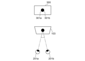
- FIG. 1 is an explanatory diagram showing an example of displaying a stereoscopic image using parallax.
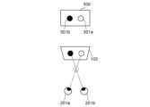
- FIG. 1 is an explanatory diagram showing an example of displaying a stereoscopic image using parallax.
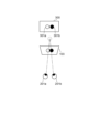
- FIG. 1 is an explanatory diagram showing an example of displaying a stereoscopic image using parallax.
- 1 is an explanatory diagram showing the convergence angle and diopter of the eyeballs when gazing at an object.
- 1 is an explanatory diagram showing the convergence angle and diopter of the eyeballs when gazing at an object.
- 1 is an explanatory diagram showing the convergence angle and diopter of the eyeballs when gazing at an object.
- 4 is a flowchart illustrating an operation of the image display device according to the first embodiment.
- 5A and 5B are explanatory diagrams showing changes in physiological or psychological states and lens positions in the first embodiment.
- FIG. 10 is an explanatory diagram showing a modification of the schematic configuration of the image display device according to the first embodiment.
- 13A and 13B are explanatory diagrams showing a physiological state or a psychological state and a change in a lens position in a modified example of the image display device of the first embodiment.
- FIG. 10 is a flowchart illustrating an operation of the image display device according to the second embodiment.
- 13 is an explanatory diagram showing a change in a physiological state or a psychological state and a maximum drive speed in the second embodiment.
- FIG. 10 is a flowchart illustrating the operation of a modified example of the image display device of the second embodiment.
- 13 is an explanatory diagram showing a change in physiological state or psychological state and a maximum drive speed in a modified example of the image display device of the second embodiment.
- a head-mounted display will be shown and described as an example of an image display device in which a pair of images having parallax are displayed by a plurality of image display units, and stereoscopic display can be performed via a plurality of display optical elements.
- the image display device of the present invention comprises a first and a second image display section that respectively display a first and a second image to the right and left eyes of a user. It further comprises a first and a second display optical element corresponding to the first and the second image display section, respectively, and an actuator that changes the position of the display optical element.
- the image display device changes at least one of the position of the first display optical element relative to the first image display section and the position of the second display optical element relative to the second image display section by driving the actuator based on the detection result of the physiological state or psychological state of the user while using the image display device.
- the image display device, the control method for the image display device, and the program thereof can be configured in any desired combination.
- FIG. 1 is a diagram showing a schematic configuration of an image display device 100 according to a first embodiment of the present invention.
- the image display device 100 comprises an image acquisition unit 101 and a display processing unit 102.
- the image acquisition unit 100 acquires an image to be displayed on the image display unit 103 through an external device or network (not shown).
- the display processing unit 102 performs processing such as adjusting the display magnification of the acquired image.
- the processed image is sent to the image display units 103a and 103b and displayed.
- the image is divided and displayed on each of the image display units 103a and 103b, but the present invention is not limited to this configuration, and a single screen may be divided into two regions and an image corresponding to each of the divided image display units may be displayed.
- the image display device 100 has a first and a second display optical element corresponding to the left eye 201a and the right eye 201b, respectively.
- the first display optical element can have a lens 104a
- the second display optical element can have a lens 104b.
- the images displayed on the image display units 103a and 103b are presented to the left eye 201a and the right eye 201b, respectively, through the corresponding lenses 104a and 104b.
- the lenses can be convex lenses as shown in FIG. 1.
- Lens 104a, 104b are driven by actuators 105a, 105b and can move in the direction along the optical axis of the lens (arrows 107a, 107b).
- the optical axes 202a, 202b of lenses 104a, 104b are described as passing through the centers of image display units 103a, 103b and left eye 201a, right eye 201b, respectively, but this is not limited to the above.
- FIG. 2A and 2B are explanatory diagrams that show the state when the lenses 104a and 104b are moved by the actuators 105a and 105b.
- FIG. 2A shows the state when the lenses 104a and 104b are moved close to the image display units 103a and 103b, respectively.
- Figure 2B is a diagram showing the state when lenses 104a, 104b are moved close to left eye 201a and right eye 201b, respectively.
- a user of image display device 100 views image display units 103a, 103b with left eye 201a and right eye 201b through lenses 104a, 104b, virtual images 203a, 203b are viewed.
- the positions of virtual images 203a, 203b in the directions of optical axes 202a, 202b, based on the positions of left eye 201a and right eye 201b are defined as virtual image formation position X.
- the virtual image formation position X approaches the left eye 201a and the right eye 201b.
- the virtual image formation position X moves away from the left eye 201a and the right eye 201b. In this way, the diopter can be changed by moving the lenses 104a and 104b with the actuators 105a and 105b.
- the virtual image forming position X approaches the left eye 201a and the right eye 201b when the lenses 104a and 104b approach the image display units 103a and 103b, but this is not limited to this.
- the virtual image forming position X may be moved away from the left eye 201a and the right eye 201b when the lenses 104a and 104b approach the image display units 103a and 103b.
- the actuators 105a and 105b move the lenses 104a and 104b to change the diopter, but this is not limited to the movement of optical members.
- a liquid lens may be used, and the position of the boundary surface formed by water and oil may be changed by an electrical signal applied from the actuators 105a and 105b.
- an electromagnetic motor such as an ultrasonic motor or a voice coil motor, which is a vibration type actuator that is highly quiet, as the actuator that changes the diopter.
- the lenses 104a and 104b are represented as a single convex lens in Figures 1, 2A, and 2B, each may be a multiple lens, and the position of a specific lens may be moved when the diopter is changed.
- the parallax image 300 displayed on the image display units 103a and 103b will be described with reference to Figures 3A to 3C.
- Figures 3A to 3C are explanatory diagrams of an example of an image.
- the parallax image 300 is composed of, for example, a left eye image 301a displayed on the image display unit 103a corresponding to the left eye 201a, and a right eye image 301b displayed on the image display unit 103b corresponding to the right eye 201b.
- the parallax image 300 is composed of an image 301a for the left eye and an image 301b for the right eye, but the present invention is not limited to this.
- a configuration in which the display processing unit 102 processes the image based on three-dimensional data and generates parallax images to be displayed on the two image display units 103a and 103b may be used.
- an image captured by a camera mounted on the image display device 100 may be treated as at least a part of the parallax image 300.
- the image display device 1 it becomes possible for the image display device 1 to display an image in an augmented reality space representation format.
- the parallax image 300 is created by superimposing an image captured by a camera mounted on the image display device 1 on an image based on three-dimensional data created in advance, and a composite image is displayed.
- the image 301a and 301b are each one, but the present invention is not limited to this.
- the image captured by the camera may be configured to display multiple objects.
- the device is equipped with gaze detection means 106a and 106b as shown in FIG. 1 that can detect the gaze direction of the user's left eye 201a and right eye 201b, and a process is performed in which the gaze point at which the user's gaze is directed is treated as the images 301a and 301b.
- the gaze detection means can be an infrared illumination unit and a gaze detection camera, etc.
- the diopter adjustment amount calculation unit 111 calculates the diopter adjustment amount based on the depth information at the position of the gaze point determined from the detection result by the gaze detection means 106a, 106b. Based on this calculated diopter adjustment amount, the control unit 108 outputs a drive command to drive the actuators 105a, 105b and adjust the diopter.
- the diopter is adjusted by changing the respective distances between the image display units 103a, 103b and the lenses 104a, 104b.
- the diopter detection means 106a, 106b allow the user to adjust the diopter in real time each time the gaze point is changed.
- the control unit 108 is a so-called microcomputer, and may be composed of electrical components such as a central processing unit (CPU), a memory for storing programs, and a memory serving as a working area in which the programs are deployed. In this case, the control unit 108 is responsible for generating signals having information for controlling the drive of the actuator 105.
- CPU central processing unit
- memory for storing programs
- memory serving as a working area in which the programs are deployed.
- the control unit 108 is responsible for generating signals having information for controlling the drive of the actuator 105.
- FIGS. 4A to 4C are diagrams explaining the convergence angle and visibility of the eyes when gazing at an object.
- FIG. 4A shows the state when gazing in the real world
- FIG. 4B shows the state when gazing at the image display device 100.
- the virtual image position 402 is the virtual image position when the user views the image display units 103a and 103b through the lenses 104a and 104b (not shown), respectively.
- the virtual image position 402 is a position that is a distance B away from the left eye 201a and right eye 201b.
- the image display device 100 is different in that the distance corresponding to the convergence angle ⁇ does not match the distance B corresponding to the visibility. This is known as a contradiction between convergence and visibility adjustment, and if this state continues, the user will feel more drowsy and fatigued.
- the virtual image position 402 can be changed by changing the distance between the image display units 103a, 103b and the lenses 104a, 104b (not shown). For example, if the gaze detection means detects that the user is gazing at the object 401, the distance between the display units and the lenses is changed so that the virtual image position 402, which is at distance B, becomes distance A. This causes the distance corresponding to the convergence angle and the distance corresponding to the visual acuity to match, as shown in Figure 4A, creating a more natural state that can reduce motion sickness and fatigue.
- the state detection unit 109 in FIG. 1 detects the physiological or psychological state of the user, for example, the user's heart rate, electrocardiogram, breathing, eye potential, skin potential, and center of gravity.
- heart rate the user's heart rate is measured, and the average instantaneous heart rate, the respiratory component in the heart rate fluctuations, and the magnitude of the Mayer wave component in the heart rate fluctuations are determined, and at least one of these is used as the detection value.
- the electrocardiogram of the user is measured, and the high frequency component (HF), low frequency component (LF), or ratio of HF and LF of the heart rate fluctuation, which is the magnitude of a specific frequency component of the baseline fluctuation of the electrocardiogram, is determined, and at least one of these is used as the detection value.
- HF high frequency component
- LF low frequency component
- ratio of HF and LF of the heart rate fluctuation which is the magnitude of a specific frequency component of the baseline fluctuation of the electrocardiogram
- the user's breathing frequency, breathing volume, and breathing irregularity are measured, and at least one of these is used as the detection value.
- the electrooculography measures the number of blinks, cumulative number, cumulative number, rate of change, and blink interval of the user, and at least one of these is used as the detection value.
- the detection value detected by the state detection unit 109 is output to the state determination unit 110, and the detection value is compared with a predetermined normal value recorded in advance to determine whether the user is experiencing drunkenness or fatigue.
- the physiological or psychological state may be determined using not only one of the electrocardiogram, respiration, electrooculography, electrodermal potential, and center of gravity, but also a combination of several of them.
- the judgment should be based on the magnitude of the resistance component. If the center of gravity is used, the judgment should be based on the fluctuation of the center of gravity.
- the control unit 108 drives the actuators 105a, 105b to move the lenses 104a, 104b toward the image display unit, thereby changing the visibility.
- This state detection unit 109 and state determination unit 110 do not necessarily have to form part of the image display unit, and can also be configured to wirelessly send and receive signals so that they can be sent and received. Conversely, by adopting an integrated configuration with the image display unit, it is possible to allow the user of the head mounted display to immediately use the state detection function without the need for remote communication.
- a program corresponding to the flowchart in FIG. 5 is stored in a memory unit in the arithmetic processing unit.
- the control unit 108 represents a CPU, memory, etc., and each process shown in the flowchart in FIG. 5 is realized by the CPU expanding a predetermined program stored in the memory.
- the configuration of the control unit 108 can also be either integrated with the image display device or not.
- the state detection unit 109 detects the physiological state or psychological state of the user.
- the state of intoxication or fatigue of the user is judged based on the detected value. If the detected value is equal to or greater than the desired value, in S503, the amount of movement is calculated to move the lenses 104a and 104b in a direction away from the image display units 103a and 103b, and in S504, the control unit 108 drives the actuators 105a and 105b.
- This amount of movement may be determined according to the detected value, or the amount of movement may be increased as the detected value increases and decreased as the detected value decreases. In this way, the displayed parallax image is not focused on and is not clearly visible, and the amount of information entering the left eye 201a and right eye 201b is reduced to relax the muscles of the eyeballs, thereby reducing intoxication and fatigue.
- the gaze detection means 106a and 106b are used to detect the gaze of the user's left eye 201a and right eye 201b in S505.
- control unit 107 performs processing to determine the gaze point from the gaze of the left eye 201a and the gaze of the right eye 201b.
- the average value of the gazes of the left eye 201a and the right eye 201b can be used.
- the diopter adjustment amount calculation unit 111 performs a process of calculating the diopter adjustment amount at the position of the gaze point of the image displayed on the image display units 103a and 103b. Specifically, the parallax between the image at the left eye gaze point position and the image at the right eye gaze point position is calculated, and the diopter adjustment amount is derived from depth information corresponding to this parallax. For example, by providing table data that associates the parallax with the diopter adjustment amount, it is possible to calculate the diopter adjustment amount corresponding to the parallax. Alternatively, the diopter adjustment amount calculation unit 111 may calculate the diopter adjustment amount from the parallax using a formula that indicates the relationship between the parallax and the diopter adjustment amount.
- the actuators 105a and 105b are driven by the control unit 108 based on the diopter adjustment amount calculated by the diopter adjustment amount calculation unit 111. This causes an operation to change the distance between the image display units 103a and 103b and the lenses 104a and 104b.
- FIG. 6 shows the detected values of the physiological or psychological state of the user and the lens position of the configuration of FIG. 1.
- the gaze point is calculated from the gaze detected by the gaze detection means, and diopter adjustment is performed in real time in the direction of the arrows 107a and 107b according to the depth information of the gaze point.
- the actuators 105a and 105b are moved so as to move the lenses 104a and 104b closer to the user and away from the image display units 103a and 103b.
- the gaze point is again calculated from the gaze detected by the gaze detection means, and diopter adjustment is performed in real time in the direction of the arrows 107a and 107b according to the depth information of the gaze point.
- the lens 104a corresponding to the left eye 201a and the lens 104b corresponding to the right eye 201b can be driven by independent actuators 105a and 105b, so it is possible to accommodate users with different vision in the left and right eyes.
- a configuration can be adopted in which the position of at least one of the first and second display optical elements can be changed.
- the visibility is adjusted according to the depth information of the gaze point, and the actuator is driven to move the lenses 104a, 104b in a direction away from the image display units 103a, 103b according to the user's state of sickness or fatigue.
- This causes the image displayed on the image display unit to appear blurred, and by reducing the amount of information the user obtains from the image, it is possible to reduce sickness and fatigue accumulated due to long-term use.
- the actuator is moved so that the image display unit and the lens move away from each other, but this is not limiting, and the actuator may be moved so that the image display unit and the lens move closer to each other, with the same effect being obtained.
- the actuator when the value detected by the state detection unit 109 exceeds a predetermined value, the lenses 104a, 104b are moved by the actuators 105a, 105b so that they move closer to the image display units 103a, 103b.
- the diopter adjustment is performed based on the depth information of the gaze point detected by the gaze detection means 106a, 106b.
- the diopter adjustment may be performed manually in a configuration as shown in FIG. 7.
- FIG. 8 shows the detection value of the physiological state or psychological state of the user and the lens position in the configuration of FIG. 7.
- the user himself manually adjusts the diopter to a position that matches the image being viewed at time t0, and this position is set as the reference position of the lens.
- the actuator When the value detected by the state detection unit exceeds a predetermined value at time t1, the actuator is moved so as to move the lens closer to the user and away from the display unit. After that, if the detected value falls below the desired value at time t2, the actuator is moved so as to return the lens to the same reference position that was manually adjusted at time t0.
- a program corresponding to the flowchart in FIG. 9 is stored in a storage unit in the arithmetic processing unit.
- the control unit 108 indicates a CPU, memory, etc., and each process shown in the flowchart in FIG. 9 is realized by the CPU expanding a predetermined program stored in the memory.
- the state detection unit 109 detects the physiological state or psychological state of the user.
- the state of intoxication or fatigue of the user is judged based on the detected value. If the detected value is equal to or lower than the desired value, in S1003, the control unit 108 sets the maximum drive speed of the actuators 105a and 105b to A (for example, 100 mm/s). If the detected value is equal to or higher than the desired value, in S1004, the control unit 108 sets the maximum drive speed of the actuators 105a and 105b to B (for example, 50 mm/s) which is smaller than A.
- gaze detection is performed on the left eye 201a and right eye 201b of the user using gaze detection means 106a and 106b.
- control unit 108 performs processing to determine the gaze point from the gaze of the left eye 201a and the gaze of the right eye 201b.
- the average value of the gazes of the left eye 201a and the right eye 201b can be used.
- the diopter adjustment amount calculation unit 111 performs a process of calculating the diopter adjustment amount at the position of the gaze point of the image displayed on the image display units 103a and 103b. Specifically, the parallax between the image at the left eye gaze point position and the image at the right eye gaze point position is calculated, and the diopter adjustment amount is derived from depth information corresponding to this parallax. For example, by providing table data that associates the parallax with the diopter adjustment amount, it is possible to calculate the diopter adjustment amount corresponding to the parallax. Alternatively, the diopter adjustment amount calculation unit 111 may calculate the diopter adjustment amount from the parallax using a formula that indicates the relationship between the parallax and the diopter adjustment amount.
- the actuators 105a and 105b are driven by the control unit 108 based on the diopter adjustment amount calculated by the diopter adjustment amount calculation unit 111. This changes the distance between the image display units 103a and 103b and the lenses 104a and 104b. Since the above operation is performed every time the gaze point is changed, the diopter can be adjusted in real time to change the diopter.
- Figure 10 shows the detected values of the physiological or psychological state of the user and the maximum drive speed of the actuators 105a, 105b.
- the maximum drive speed of the actuators 105a, 105b is set to A.
- the maximum drive speed is set to B, which is smaller than the maximum drive speed A.
- the maximum drive speed is again set to A.
- control gain is the ratio of the control output required to change the actuator by a certain amount, and by reducing this ratio, the responsiveness can be suppressed, the amount of change in the user's focus on the image can be suppressed, and the eyes can be reduced from trying to follow a sudden change in focus. This reduces the burden on the user, even when watching videos for a long period of time, and can reduce the increase or accumulation of sickness and fatigue.
- the control period is the time interval for issuing commands in controlling the actuator, and by widening this time interval, the frequency of updates can be suppressed, the amount of change in the user's focus on the image can be suppressed, and the eyes can be reduced from trying to follow a sudden change in focus. This reduces the burden on the user, even when watching videos for a long period of time, and can reduce the increase or accumulation of sickness and fatigue.
- the value detected by the state detection unit 109 is equal to or greater than a predetermined value, multiple of the maximum drive speed, control gain, and control period may be changed simultaneously.
- the maximum drive speed, control gain, and control cycle are changed depending on whether the detection value of the state detection unit 109 exceeds a predetermined value.
- the maximum drive speed, control gain, and control cycle may be changed depending on the detection value, as shown in the flowchart of FIG. 11.
- the state detection unit 109 is used to detect the physiological state or psychological state of the user.
- the control unit 108 sets the maximum drive speed of the actuators 105a and 105b based on the detected value.
- the maximum drive speed can be calculated depending on the detection value of the physiological state or psychological state.
- the maximum drive speed may be calculated using a formula that indicates the relationship between the detection value of the physiological state or psychological state and the maximum drive speed.
- FIG. 12 shows the detected values of the physiological or psychological state of the user and the maximum drive speed of the actuators 105a and 105b. As shown in FIG. 12, the maximum drive speed of the actuators 105a and 105b is set in stages according to the values detected by the state detection unit 109.
- control gain and control period may be changed to obtain the same effect.
- the control gain and control period may be changed simultaneously.
- a program that realizes one or more of the functions of the above-described embodiments can be supplied to a system or device via a network or storage medium, and one or more processors in the computer of the system or device can read and execute the program. It can also be realized by a circuit (e.g., an ASIC) that realizes one or more functions.
- a circuit e.g., an ASIC
- Image display device 101 Image acquisition unit 102 Display processing unit 103 Image display unit 104 Lens 105 Actuator 106 Line-of-sight detection means 107 Driving direction 108 Control unit 109 State detection unit 110 State determination unit 111 Depth information calculation unit 201a Left eye 201b Right eye 202 Optical axis 203 Virtual image
Landscapes
- Health & Medical Sciences (AREA)
- Life Sciences & Earth Sciences (AREA)
- Engineering & Computer Science (AREA)
- Physics & Mathematics (AREA)
- Animal Behavior & Ethology (AREA)
- Veterinary Medicine (AREA)
- Cardiology (AREA)
- Public Health (AREA)
- General Health & Medical Sciences (AREA)
- Biophysics (AREA)
- Surgery (AREA)
- Biomedical Technology (AREA)
- Heart & Thoracic Surgery (AREA)
- Medical Informatics (AREA)
- Molecular Biology (AREA)
- Pathology (AREA)
- Multimedia (AREA)
- Signal Processing (AREA)
- Ophthalmology & Optometry (AREA)
- Optics & Photonics (AREA)
- General Physics & Mathematics (AREA)
- Educational Technology (AREA)
- Developmental Disabilities (AREA)
- Child & Adolescent Psychology (AREA)
- Hospice & Palliative Care (AREA)
- Psychiatry (AREA)
- Psychology (AREA)
- Social Psychology (AREA)
- Human Computer Interaction (AREA)
- Measurement And Recording Of Electrical Phenomena And Electrical Characteristics Of The Living Body (AREA)
- Eye Examination Apparatus (AREA)
- Mechanical Light Control Or Optical Switches (AREA)
- Measurement Of The Respiration, Hearing Ability, Form, And Blood Characteristics Of Living Organisms (AREA)
Abstract
上記課題を解決する本願にかかる映像表示装置は、使用者の右眼および左眼に対して第1および第2の映像をそれぞれ表示する第1および第2の映像表示部と、前記第1および第2の映像表示部にそれぞれ対応する第1および第2の表示光学素子と、前記表示光学素子の位置を変えるアクチュエータと、を備える前記映像表示装置であって、前記映像表示装置を使用中の使用者の生理的な状態あるいは心理的な状態の検知結果に基づいて前記アクチュエータを駆動することで、前記第1および第2の表示光学素子のうち少なくとも一方の位置の変更を行うことを特徴とする。
Description
本発明は、映像表示装置における視度調整の技術に関する。
使用者が頭部に装着して使用するヘッドマウントディスプレイのような映像表示装置や、使用者が眼鏡のように装着して使用する映像表示装置がある。使用者の眼の近傍に表示部が配置され、使用者の左右それぞれの眼に対して視差映像の表示処理が行われる。表示される視差映像を使用者が視認することによって、視差映像に表示された物体についての立体感が得られる。
この映像表示装置で使用者の視線は左右それぞれの眼に対して表示された映像によって生成される立体映像の位置に調節されるが、焦点位置は表示画面上の左右各々の画像に調節される。これは現実の物体を視認する場合には生じ得ない不自然な状態となる。
例えば、視差映像として表示される物体の像を使用者が見ると、使用者の輻輳角は、その表示された物体の位置に応じて変化する。この時、現実空間での経験に基づいて水晶体の焦点距離は輻輳角の大きさに応じて変化する。この場合、水晶体の焦点距離と映像表示装置の視度とが不一致となる可能性があり、表示された視差映像に焦点が合わず、鮮明に見ることが困難となる等、良好な視認性が確保できないことがある。そのため、映像表示装置の視度調整では、装置内のレンズを駆動する方法等により、使用者の輻輳角を定める視差映像内の深度情報に応じて視度を変更することが望ましい。
特許文献1では、映像を視聴した際の使用者の注視点の位置に応じた深度情報に対する視度調整を、個人差や映像表示装置の使用状態に対応して行うことで、立体視時の違和感を低減することを可能としている。
しかしながら、視度調整することで立体視時の違和感は低減されても、長時間の映像視聴を継続した場合、使用者の体調変化や視度調整のずれなどの積み重ねにより、酔いや疲労が蓄積してしまう。特に、視差映像に表示された物体が使用者の手前側の位置に表示される映像を長時間視聴した場合、酔いや疲労が多く生じることが知られている。映像表示装置の使用者はゲームやライブなど、長時間の視聴が行われる機会が多く、使用者にとっても酔いや疲労を感じることは快くない。
そこで本発明は、使用者に視差による立体映像を提供しつつ、長時間の映像視聴時の使用者への負担を低減することのできる映像表示装置を提供することを目的としている。
上記の目的を達成する映像表示装置は、
使用者の右眼に対して第1の映像を表示する第1の映像表示部と、
前記使用者の左眼に対して第2の映像を表示する第2の映像表示部と、
前記第1の映像表示部に対応する第1の表示光学素子と、
前記第2の映像表示部に対応する第2の表示光学素子と、
前記表示光学素子の位置を変えるアクチュエータと、を備える映像表示装置であって、
前記映像表示装置を使用中の使用者の生理的な状態あるいは心理的な状態を検知する状態検出部をさらに備え、前記状態検出部の検知結果に基づいて前記アクチュエータを駆動することで、前記第1の映像表示部に対する前記第1の表示光学素子の位置、および前記第2の映像表示部に対する前記第2の表示光学素子の位置のうち少なくとも一方の位置の変更を行うこと、を特徴とする。
使用者の右眼に対して第1の映像を表示する第1の映像表示部と、
前記使用者の左眼に対して第2の映像を表示する第2の映像表示部と、
前記第1の映像表示部に対応する第1の表示光学素子と、
前記第2の映像表示部に対応する第2の表示光学素子と、
前記表示光学素子の位置を変えるアクチュエータと、を備える映像表示装置であって、
前記映像表示装置を使用中の使用者の生理的な状態あるいは心理的な状態を検知する状態検出部をさらに備え、前記状態検出部の検知結果に基づいて前記アクチュエータを駆動することで、前記第1の映像表示部に対する前記第1の表示光学素子の位置、および前記第2の映像表示部に対する前記第2の表示光学素子の位置のうち少なくとも一方の位置の変更を行うこと、を特徴とする。
本発明の映像表示装置によれば、長時間の映像視聴時の使用者の酔いや疲労の状態に応じて、視差による立体映像を表示した際の使用者への負担を軽減することができる。
以下、本発明の実施形態について、添付図面を参照して詳細に説明する。実施形態では、視差を有する一対の映像を複数の映像表示部がそれぞれ表示し、複数の表示光学素子を介して立体視表示を行うことが可能な映像表示装置の例として、ヘッドマウントディスプレイを示して説明する。
本発明の映像表示装置は、使用者の右眼および左眼に対して第1および第2の映像をそれぞれ表示する第1および第2の映像表示部を備えている。さらには、第1および第2の映像表示部にそれぞれ対応する第1および第2の表示光学素子と、表示光学素子の位置を変えるアクチュエータと、を備える。その上で、映像表示装置を使用中の使用者の生理的な状態あるいは心理的な状態の検知結果に基づいてアクチュエータを駆動することで、第1の映像表示部に対する第1の表示光学素子の位置、および第2の映像表示部に対する第2の表示光学素子の位置のうち少なくとも一方の位置の変更を行う映像表示装置である。
また本発明は、以下に示す実施形態は代表的な構成例であり、その記載に限られることはなく、本発明の趣旨を逸脱しない限り、所望の組み合わせにて映像表示装置、映像表示装置の制御方法、およびそのプログラムを構成することができる。
<第1実施形態>
図1は、本発明の第1実施形態に係る映像表示装置100の概略構成を示す図である。
図1は、本発明の第1実施形態に係る映像表示装置100の概略構成を示す図である。
映像表示装置100は、映像取得部101と表示処理部102を備える。映像取得部100は映像表示部103に表示する表示用の映像を不図示の外部装置やネットワーク等を通じて取得する。表示処理部102は取得された映像に対して表示倍率の調整処理等を行う。処理された映像は、映像表示部103a、103bに送られて表示される。例えば、映像を映像表示部103a、103bのそれぞれへ映像を分割して表示する構成であるが、この構成に限定されることなく、ひとつの画面を2つに領域分割して、分割されたそれぞれの映像表示部に対応する映像を表示する構成でもよい。
映像表示装置100は、左眼201a、右眼201bにそれぞれ対応する第1および第2の表示光学素子を備える。例えば、第1の表示光学素子はレンズ104aを有し、第2の表示光学素子はレンズ104bを有する構成を採ることができる。映像表示部103a、103bに表示された映像はそれぞれに対応するレンズ104a、104bを通して、左眼201a、右眼201bのそれぞれに対して提示される。レンズとしては図1に示す凸レンズを用いることができる。
レンズ104a、104bは、アクチュエータ105a、105bにより駆動され、レンズの光軸に沿う方向(矢印107a、107b)に移動することができる。本実施形態においては、レンズ104a、104bの光軸202a、202bが、映像表示部103a、103bおよび左眼201a、右眼201bの中心をそれぞれ通るものとして説明するが、これに限定されるものではない。
図2A、図2Bは、アクチュエータ105a、105bによってレンズ104a、104bが移動する時の状態を模式的に示した説明図である。図2Aは、レンズ104a、104bを映像表示部103a、103bの近くにそれぞれ移動させた時の状態を示す図である。
図2Bは、レンズ104a、104bを左眼201a、右眼201bの近くにそれぞれ移動させた時の状態を示す図である。映像表示装置100の使用者は、その左眼201a、右眼201bで映像表示部103a、103bを、レンズ104a、104bを通して見た時に虚像203a,203bを視認する。ここで、左眼201a、右眼201bの位置を基準とした、光軸202a、202bの方向の虚像203a、203bの位置を、虚像結像位置Xとして定義する。レンズ104a、104bの位置を変更することによって、虚像結像位置Xを変更することができる。例えば、図2Aに示すように、レンズ104a、104bが映像表示部103a、103bに近づくにつれて、虚像結像位置Xは左眼201a、右眼201bに近づいていく。逆に、図2Bに示すように、レンズ104a、104bが左眼201a、右眼201bに近づくと、虚像結像位置Xは左眼201a、右眼201bから遠ざかる。このように、アクチュエータ105a、105bによってレンズ104a、104bを移動することにより、視度の変更が可能となる。
本実施形態ではレンズ104a、104bが映像表示部103a、103bに近づくと、虚像結像位置Xは左眼201a、右眼201bに近づく構成を示したが、これに限定されることはない。レンズ104a、104bが映像表示部103a、103bに近づくと、虚像結像位置Xが左眼201a、右眼201bから遠ざかる構成であってもよい。また、視度を変更するために、アクチュエータ105a、105bによってレンズ104a、104bを移動させる構成を示したが、光学部材の移動に限定されない。また、レンズ104a、104bを移動させる別の構成として、例えば液体レンズを採用して、アクチュエータ105a、105bから加えられた電気信号により水と油などで構成される境界面の位置を変化させる実施形態であってもよい。また、ヘッドマウントディスプレイに代表される映像表示装置100は使用者の耳の近傍に配置して利用されるため、視度変更を行うアクチュエータとして静粛性の高い、振動型アクチュエータとしての超音波モータやボイスコイルモータなどの電磁モータを用いることが好ましい。また、図1、図2A、図2Bでは、レンズ104a、104bを1枚の凸レンズで表現しているが、それぞれを複数枚のレンズとして、視度変更時に所定のレンズの位置を移動させる構成であってもよい。
図3A~図3Cを参照して、映像表示部103a、103bに表示する視差映像300について説明する。図3A~図3Cは、映像の一例についての説明図である。視差映像300は、例えば、左眼201aに対応する映像表示部103aに表示される左眼用映像301aおよび右眼201bに対応する映像表示部103bに表示される右眼用映像301bから構成される。
本実施形態では、視差映像300が左眼用映像301a、右眼用301bから構成される例を示すが、これに限定されることはない。例えば3次元データに基づいて表示処理部102で処理され、2つの映像表示部103a、103bそれぞれに表示される視差映像が生成される構成でもよい。また、映像表示装置100に搭載されたカメラで撮影された映像を視差映像300の少なくとも一部として扱ってもよい。このような構成によって、映像表示装置1にて拡張現実空間の表現形式で映像を表示することが可能となる。例えば映像表示装置1に搭載されたカメラで撮影した映像と、事前に作成された3次元データに基づく映像とを重ね合わせることで視差映像300が作成されて、合成映像が表示される。
例えば、図3Aに示すように、使用者の視線と交差する場所が表示映像のちょうど画面と同じになると、表示映像内にある映像301a、301bは映像表示部103と同じ位置になるように見える。また、図3Bに示すように、表示映像内の映像301a、301bが使用者の視線と交差する場所が映像表示部103より手前になると、映像表示部103に対して飛び出したように見える。さらに、図3Cに示すように、表示映像内の映像301a、301bが使用者の視線の交差する場所が映像表示部103より後ろの位置になると、映像表示部103に対して映像が画面のずっと奥にあるように見える。
本実施形態においては、映像301a、301bが、それぞれ一つの場合を示すが、これに限定されることはない。例えばカメラで撮影した映像に複数の物体が表示される構成でもよい。その場合、使用者の左眼201a、右眼201bの視線方向を検知可能な、図1に示すような視線検出手段106a、106bが装置に搭載され、使用者の視線が向いている注視点を、映像301a、301bとして扱う処理が行われる。視線検出手段は、赤外照明部および視線検出カメラなどを用いることできる。
視度調整量算出部111は、視線検出手段106a、106bによる検出結果から決定される注視点の位置における深度情報に基づいて視度調整量を算出する。この算出された視度調整量に基づいて、制御部108は駆動指令を出力することでアクチュエータ105a、105bを駆動し、視度調整を行う。映像表示部103a、103b、とレンズ104a、104bとの、それぞれの間隔を変更することで視度が調整される。例えば、視度検出手段106a、106bによって、使用者が視度調整は注視点が変更される度にリアルタイムで実行される。
なお、制御部108は、所謂、マイクロコンピュータであり、演算装置(CPU)やプログラムを格納するメモリ及びプログラムが展開される作業領域としてのメモリ等の電気部品から構成されてよい。その場合、制御部108はアクチュエータ105の駆動を制御するための情報を有する信号を生成する役割を担うものである。
図4A~図4Cは対象物を注視した際の眼球の輻輳角と視度について説明する図である。図4Aは現実世界における注視時の状態を示し、図4Bは映像表示装置100における注視時の状態を示したものである。
図4Aにて、現実世界では使用者は距離Aだけ離れた位置にある対象物401を注視している状態である。使用者の左眼201aの視線と、使用者の右眼201bの視線が対象物401上で交わり、角度αを成す。角度αは使用者が対象物401を注視した時の輻輳角に相当する。そのため、現実世界では輻輳角αに対応する距離と視度に対応する距離Aが常に一致した状態となる。
一方で、図4Bでは、映像表示装置100にて使用者が距離Aだけ離れた位置にある物体401を注視している状態である。輻輳角αについては、図4Aに示される現実世界の場合と同じである。虚像位置402は、使用者が映像表示部103a、103bをレンズ104a、104b(図示せず)をそれぞれ通して視聴した場合の虚像位置である。虚像位置402は、左眼201a、右眼201bから距離Bだけ離れた位置である。
虚像位置402に対して輻輳角αを与えることで、使用者はあたか対象物401にあるように視覚で認識する。しかしながら映像表示装置100は現実世界と異なり、輻輳角αに対応する距離と視度に対応する距離Bとが一致していない。これが輻輳と視度調整の矛盾といわれるもので、この状態が継続された状態になると、使用者の酔いや疲労が増加する。
そこで、図4Cのように、映像表示部103a、103bをレンズ104a、104b(図示せず)との間隔を変更することで、虚像位置402を変化させることができる。例えば、視線検出手段により、使用者が対象物401を注視していることが検出された場合、距離Bにある虚像位置402が距離Aとなるように、表示部とレンズとの間隔が変更される。これにより、図4Aで示すように、輻輳角に対応する距離と視度に対応する距離とが一致し、より自然な状態とすることで、酔いや疲労を軽減することができる。
なお、表示部とレンズとの間隔を変更する場合、表示部とレンズのうち、少なくとも一方を駆動すれば良い。
図1の状態検出部109は、使用者の生理的な状態あるいは心理的な状態を検出するものであり、例えば使用者の心拍や心電図や呼吸、眼電位、皮膚電位、重心を検出する。
心拍としては、使用者の心拍を測定し、瞬時心拍数の平均値や心拍変動中の呼吸性成分、および心拍変動中のメイヤー波成分の大きさを決定し、これらのうち少なくとも1つ以上を検出値として用いるようにする。
心電図としては、使用者の心電図を測定し、心電図の基線変動の特定の周波数成分の大きさである、心拍変動の高周波成分(HF)、低周波成分(LF)、またはHFとLFの比率を決定し、これのうち少なくとも1つを検出値として用いるようにする。
呼吸としては、使用者の呼吸周波数、呼吸の大きさ、および呼吸の不規則性を測定し、これらのうち少なくとも1つ以上を検出値として用いるようにする。
眼電位としては、使用者の瞬目数、累積回数、累積数、変化率、瞬目間隔を測定し、これのうち少なくとも1つを検出値として用いるようにする。
また、使用者の重心を測定し、その重心動揺の大きさを検出値として用いるようにしてもよい。
状態検出部109によって検出された検出値を状態判定部110に出力し、検出値と所定値である予め記録された正常値との比較することで、使用者に酔いや疲労が発生しているかを判定する。なお、心電図や呼吸、眼電位、皮膚電位、重心のうち、いずれかだけではなく、複数を組み合わせて生理な状態あるいは心理的な状態を判定するようにしても良い。
皮膚電位による場合、その抵抗成分の大きさに基づいて、判定するとよい。重心による場合、重心揺動に基づいて判定するとよい。
使用者が酔いや疲労を発生していると判定された場合、制御部108により、アクチュエータ105a、105bを駆動することによってレンズ104a、104bを、映像表示部側へ移動させることで視度を変更する。この状態検出部109や状態判定部110はかならずしも映像表示装置の一部を構成しなくてもよく、信号の送受信が可能なように無線で信号の授受ができるように構成することもできる。逆に、映像表示装置と一体構成を採ることでヘッドマウントディスプレイの利用者が、遠隔通信を介することなく、直ちに状態検出の機能を利用できるようにすることもできる。
図5のフローチャートを参照して、第1実施形態の動作を説明する。図5のフローチャートに対応するプログラムは演算処理部内の記憶部に格納されている。制御部108は、CPUやメモリなどを示しており、図5のフローチャートに示す各処理は、CPUがメモリに格納された所定のプログラムを展開することによって実現される。制御部108の構成もまた、映像表示装置と一体構成を採ることも、採らないこともできる。
まずS501にて、状態検出部109を用いて、使用者の生理的な状態あるいは心理的な状態を検出する。次にS502にて、検出された値をもとに、使用者の酔い疲労状態を判定する。検出値が所望の値以上であった場合、S503にて、映像表示部103a、103bから離れる方向へレンズ104a、104bを移動するように移動量を算出し、S504にて、制御部108により、アクチュエータ105a、105bを駆動する。この移動量は検出された値に応じて決定するようにしてもよく、検出値が増加するほど移動量を増加させ、検出値が減少するほど移動量を減少させるようにしても良い。このようにすることで、表示された視差映像に焦点を合わせず鮮明に見えないようにし、左眼201a、右眼201bに入る情報量を減らして眼球の筋肉を緩めるようにすることで、酔いや疲労を低減することができる。
S502にて、検出値が所望の値以下であった場合、S505にて、視線検出手段106a、106bを用いて、使用者の左眼201a、右眼201bの各視線検出が行われる。
次にS506にて、制御部107は、左眼201aの視線と、右眼201bの視線から注視点を決定する処理を行う。注視点の算出にあたっては、左眼201aと右眼201bの視線に関する平均値が用いることができる。
次にS507にて、視度調整量算出部111は、映像表示部103a、103bに表示する映像の注視点の位置における視度調整量を算出する処理を行う。具体的には、左眼の注視点位置の映像と右眼の注視点位置の映像との視差が算出され、この視差に応じた深度情報により視度調整量が導出される。例えば、視差と視度調整量とを対応付けたテーブルデータを備えることで、視差に対応する視度調整量を算出することができる。あるいは、視差と視度調整量との関係を示す数式により視度調整量算出部111で視差から視度調整量を算出するようにしても良い。
次にS508にて、視度調整量算出部111で算出された視度調整量に基づき、制御部108により、アクチュエータ105a、105bが駆動される。これにより、映像表示部103a、103bとレンズ104a、104bとの間隔を変更する動作が行われる。
以上の動作は、注視点が変更される度に行われるため、リアルタイムに視度調整を行って視度を変更することができる。
図6は、使用者の生理的な状態あるいは心理的な状態の検出値と、図1の構成のレンズ位置を示したものである。図6に示すように、時刻t0からt1の期間において、視線検出手段により検出された視線から注視点を算出し、その注視点の深度情報に応じて矢印107a、107bの方向へ視度調整をリアルタイムに行う。状態検出部により検出された状態検出値が時刻t1において所定値を上回った際に、映像表示部103a、103bから離れるように使用者側へレンズ104a、104bを近づけるようにアクチュエータ105a、105bを動かすようにする。その後、検出された値が時刻t2において、所望の値を下回った場合は、再び視線検出手段により検出された視線から注視点を算出し、その注視点の深度情報に応じて矢印107a、107bの方向へ視度調整をリアルタイムに行うようにする。
なお、この状態検出値の逆数を評価対象として、状態検出値の逆数がある値を下回る場合を基準とする構成を採用することができ、この場合も“所定値を上回った”ことと同義である。
なお、本実施例では、左眼201aに対応したレンズ104aと、右眼201bに対応したレンズ104bは独立したアクチュエータ105a、105bの駆動を行うことができるため、左右の視力が異なる使用者にも対応することが可能である。すなわち第1および第2の表示光学素子のうち少なくとも一方の位置の変更を行う構成をとることができる。
本実施例によれば、視線の注視点の深度情報に応じた視度調整を行う共に、使用者の酔いや疲労状態に応じて、映像表示部103a、103bから離れる方向へレンズ104a、104bを移動するようにアクチュエータを駆動させる。これにより、映像表示部に表示される映像がぼやけるように視認されるようになり、使用者が映像から取得する情報量を減少させることで、長時間使用による蓄積した酔いや疲労を低減することができる。
また、上記の例では、映像表示部とレンズが互いに離れるようにアクチュエータを動かすことで説明したが、これに限らず、映像表示部とレンズが互いに近づくようにアクチュエータを動かすようにしてもよく、同等の効果を得ることができる。この場合、状態検出部109により検出された値が所定値を上回った際に、映像表示部103a、103bへ近づくようにレンズ104a、104bをアクチュエータ105a、105bにより動かすようにする。
なお、ここまで、視線検出手段106a、106bにより検出された注視点の深度情報に基づいて視度調整を行う構成を前提として説明をしてきたが、これに限らず、図7に示すような構成で、視度調整は手動で行うような構成であってもよい。図8は、使用者の生理的な状態あるいは心理的な状態の検出値と、図7の構成のレンズ位置を示したものである。このような構成の場合、図8に示すように、時刻t0において使用者本人が手動で視聴映像に合わせた位置に視度調整を行い、その位置をレンズの基準位置とする。状態検出部により検出された値が時刻t1において所定値を上回った際に、表示部から離れるように使用者側へレンズを近づけるようにアクチュエータを動かすようにする。その後、検出された値が時刻t2において、所望の値を下回った場合は、時刻t0の時と同じ手動で合わせたレンズの基準位置へ戻すようにアクチュエータを動かすようにする。
<第2実施形態>
上述した第1実施形態において、状態検出部109により検出された値を用いて制御部108により駆動するアクチュエータ105a、105bの動作方法について説明する。原理や構成などは第1実施例と同様のため、省略する。
上述した第1実施形態において、状態検出部109により検出された値を用いて制御部108により駆動するアクチュエータ105a、105bの動作方法について説明する。原理や構成などは第1実施例と同様のため、省略する。
図9のフローチャートを参照して、第2実施形態の動作を説明する。図9のフローチャートに対応するプログラムは演算処理部内の記憶部に格納されている。制御部108は、CPUやメモリなどを示しており、図9のフローチャートに示す各処理は、CPUがメモリに格納された所定のプログラムを展開することによって実現される。
まずS1001にて、状態検出部109を用いて、使用者の生理的な状態あるいは心理的な状態を検出する。次にS1002にて、検出された値をもとに、使用者の酔い疲労状態を判定する。検出値が所望の値以下であった場合、S1003にて、制御部108において、アクチュエータ105a、105bの最大駆動速度をAに設定する(例えば100mm/s)。検出値が所望の値以上であった場合、S1004にて、制御部108において、アクチュエータ105a、105bの最大駆動速度をAよりも小さいBに設定する(例えば50mm/s)。このように最大駆動速度を変更することで、使用者の映像に対する焦点の変化量を抑えることができ、眼が焦点の急な変化に対して追従しようとすることを減らすことができる。これにより、長時間の映像視聴時においても、使用者への負担を減らすことで、酔いや疲労の増加あるいは蓄積を低減することができる。
次に、S1005にて、視線検出手段106a、106bを用いて、使用者の左眼201a、右眼201bの各視線検出が行われる。
次にS1006にて、制御部108は、左眼201aの視線と、右眼201bの視線から注視点を決定する処理を行う。注視点の算出にあたっては、左眼201aと右眼201bの視線に関する平均値を用いることができる。
次にS1007にて、視度調整量算出部111は、映像表示部103a、103bに表示する映像の注視点の位置における視度調整量を算出する処理を行う。具体的には、左眼の注視点位置の映像と右眼の注視点位置の映像との視差が算出され、この視差に応じた深度情報により視度調整量が導出される。例えば、視差と視度調整量とを対応付けたテーブルデータを備えることで、視差に対応する視度調整量を算出することができる。あるいは、視差と視度調整量との関係を示す数式により視度調整量算出部111で視差から視度調整量を算出するようにしても良い。
次にS1008にて、視度調整量算出部111で算出された視度調整量に基づき、制御部108により、アクチュエータ105a、105bが駆動される。これにより、映像表示部103a、103bとレンズ104a、104bとの間隔を変更する動作が行われる。以上の動作は、注視点が変更される度に行われるため、リアルタイムに視度調整を行って視度を変更することができる。
図10は、使用者の生理的な状態あるいは心理的な状態の検出値と、アクチュエータ105a、105bの最大駆動速度を示したものである。図10に示すように、状態検出部109により検出された値が所定値未満である時刻t0からt1までは、アクチュエータ105a、105bの最大駆動速度をAに設定する。状態検出部109により検出された値が所定値以上である時刻t1からt2までは、最大駆動速度Aよりも小さい最大駆動速度Bに設定する。状態検出部109により検出された値が所定値未満である時刻t2からt3までは、再び最大駆動速度Aに設定する。
なお、ここでは最大駆動速度を変更する例で示したが、これに限らず、制御ゲイン、制御周期を変更するようにしても良く、同様の効果を得ることができる。制御ゲインは、アクチュエータを一定量変化させるのに必要な制御出力の割合のことで、この割合を小さくすることで応答性を抑え、使用者の映像に対する焦点の変化量を抑えることができ、眼が焦点の急な変化に対して追従しようとすることを減らすことができる。これにより、長時間の映像視聴時においても、使用者への負担を減らすことで、酔いや疲労の増加あるいは蓄積を低減することができる。制御周期は、アクチュエータの制御において指令を行う時間間隔のことであり、この時間間隔を広げることで更新頻度を抑え、使用者の映像に対する焦点の変化量を抑えることができ、眼が焦点の急な変化に対して追従しようとすることを減らすことができる。これにより、長時間の映像視聴時においても、使用者への負担を減らすことで、酔いや疲労の増加あるいは蓄積を低減することができる。また、状態検出部109により検出された値が所定値以上である際には、最大駆動速度、制御ゲイン、制御周期から複数を同時に変更するようにしても良い。
なお、ここまで、状態検出部109の検出値が所定値を上回ったかで最大駆動速度、制御ゲイン、制御周期を変更する例を示した。ただし、これに限らず、図11に示すフローチャートのように、検出値に応じて最大駆動速度、制御ゲイン、制御周期を変更するようにしても良い。この際には、まずS1201にて、状態検出部109を用いて、使用者の生理的な状態あるいは心理的な状態を検出する。次にS1202にて、検出された値をもとに、制御部108において、アクチュエータ105a、105bの最大駆動速度を設定する。例えば、生理的な状態あるいは心理的なの検出値と最大駆動速度を対応付けたテーブルデータを備えることで、生理的な状態あるいは心理的な状態の検出値に応じて最大駆動速度を算出することができる。あるいは、生理的な状態あるいは心理的な状態の検出値と最大駆動速度との関係を示す数式により最大駆動速度を算出するようにしても良い。このように最大駆動速度を変更することで、使用者の映像に対する焦点の変化量を抑えることができ、眼が焦点の急な変化に対して追従しようとすることを減らすことができる。これにより、長時間の映像視聴時においても、使用者への負担を減らすことで、酔いや疲労の増加あるいは蓄積を低減することができ、前述した例と同様の効果を得ることができる。
なお、図11のS1203からS1206までの動作は、前述した図9のフローチャートにおけるS1005からS1008までの動作と同様であるため、説明を省略する。
図12は、使用者の生理的な状態あるいは心理的な状態の検出値と、アクチュエータ105a、105bの最大駆動速度を示したものである。図12に示すように、状態検出部109により検出された値に応じて、アクチュエータ105a、105bの最大駆動速度を段階的に設定する。
なお、ここでは最大駆動速度を変更する例で示したが、これに限らず、制御ゲイン、制御周期を変更するようにしても良く、同様の効果を得ることができる。また、状態検出部109により検出された値が所定値以上である際には、最大駆動速度、制御ゲイン、制御周期から複数を同時に変更するようにしてもよい。
以上、本発明をその好適な実施形態に基づいて詳述してきたが、本発明はこれら特定の実施形態に限られるものではなく、この発明の要旨を逸脱しない範囲の様々な形態も本発明に含まれる。上述した各工程を実行する制御方法や、その制御方法を実行するためのコンピュータ読み取り可能な非一時的なプログラムを提供することもできる。
例えば、上述の実施形態の1以上の機能を実現するプログラムを、ネットワーク又は記憶媒体を介してシステム又は装置に供給し、そのシステム又は装置のコンピュータにおける1つ以上のプロセッサがプログラムを読み出して実行する処理でも実現可能である。また、1以上の機能を実現する回路(例えば、ASIC)によっても実現可能である。
本発明は上記実施の形態に制限されるものではなく、本発明の精神及び範囲から離脱することなく、様々な変更及び変形が可能である。従って、本発明の範囲を公にするために以下の請求項を添付する。
本願は、2023年11月29日提出の日本国特許出願特願2023-201980を基礎として優先権を主張するものであり、その記載内容の全てをここに援用する。
100 映像表示装置
101 映像取得部
102 表示処理部
103 映像表示部
104 レンズ
105 アクチュエータ
106 視線検出手段
107 駆動方向
108 制御部
109 状態検出部
110 状態判定部
111 深度情報算出部
201a 左眼
201b 右眼
202 光軸
203 虚像
101 映像取得部
102 表示処理部
103 映像表示部
104 レンズ
105 アクチュエータ
106 視線検出手段
107 駆動方向
108 制御部
109 状態検出部
110 状態判定部
111 深度情報算出部
201a 左眼
201b 右眼
202 光軸
203 虚像
Claims (21)
- 使用者の右眼に対して第1の映像を表示する第1の映像表示部と、
前記使用者の左眼に対して第2の映像を表示する第2の映像表示部と、
前記第1の映像表示部に対応する第1の表示光学素子と、
前記第2の映像表示部に対応する第2の表示光学素子と、
前記表示光学素子の位置を変えるアクチュエータと、を備える映像表示装置であって、
前記映像表示装置を使用中の使用者の生理的な状態あるいは心理的な状態を検知する状態検出部をさらに備え、前記状態検出部の検知結果に基づいて前記アクチュエータを駆動することで、前記第1の映像表示部に対する前記第1の表示光学素子の位置、および前記第2の映像表示部に対する前記第2の表示光学素子の位置のうち少なくとも一方の位置の変更を行う映像表示装置。 - 前記生理的な状態あるいは心理的な状態の検知結果が所定の値以上となった際に、前記第1の映像表示部と前記第1の表示光学素子、および、前記第2の映像表示部と前記第2の表示光学素子、のうち少なくとも一方が互いに離れる位置となるように、前記アクチュエータを駆動することを特徴とする請求項1の映像表示装置。
- 前記生理的な状態あるいは心理的な状態の検知結果が所定の値以上となった際に、前記第1の映像表示部と前記第1の表示光学素子、および、前記第2の映像表示部と前記第2の表示光学素子、のうち少なくとも一方が互いに近づく位置となるように、前記アクチュエータを駆動することを特徴とする請求項1の映像表示装置。
- 前記第1の映像表示部に係る視線検出を行う第1の視線検出手段および、前記第2の映像表示部に係る視線検出を行う第2の視線検出手段を有すること、を特徴とする請求項1乃至3のいずれか1項に記載の映像表示装置。
- 前記第1の表示光学素子および前記第2の表示光学素子を介さずに前記視線検出を行うよう構成された請求項4記載の映像表示装置。
- 前記第1の視線検出手段および前記第2の視線検出手段から取得される注視点の位置における前記第1の映像と前記第2の映像との視差に対応する視度調整量を算出する算出手段をさらに有することを特徴とする請求項1乃至3のいずれか1項に記載の映像表示装置。
- 前記映像表示装置は、駆動指令を出力する制御部を備え、前記制御部は、前記視度調整量に対応する前記駆動指令を前記アクチュエータに行うことを特徴とする請求項6記載の映像表示装置。
- 前記生理的な状態あるいは心理的な状態の検知結果の値に応じて、さらに前記アクチュエータの制御ゲインを変更すること、を特徴とする請求項1乃至3のいずれか1項に記載の映像表示装置。
- 前記生理的な状態あるいは心理的な状態の検知結果の値に応じて、さらに前記アクチュエータの制御周期を変更すること、を特徴とする請求項1乃至3のいずれか1項に記載の映像表示装置。
- 前記生理的な状態あるいは心理的な状態の検知結果の値に応じて、さらに前記アクチュエータの最大駆動速度を変更すること、を特徴とする請求項1乃至3のいずれか1項に記載の映像表示装置。
- 前記第1の視線検出手段および前記第2の視線検出手段は、赤外照明部および視線検出カメラをそれぞれ備えること、を特徴とする請求項4に記載の映像表示装置。
- 前記状態検出部は、測定された前記映像表示装置の使用者の眼電位による、瞬目数、累積回数、変化率、瞬目間の時間間隔のうち少なくとも1つに基づいて、前記生理的な状態あるいは心理的な状態の検出結果を得ることを特徴とする請求項1乃至3のいずれか1項に記載の映像表示装置。
- 前記状態検出部は、測定された前記映像表示装置の使用者の心電図による、その基線変動の周波数成分の大きさ、あるいは比率に基づいて、前記生理的な状態あるいは心理的な状態の検出結果を得ることとすることを特徴とする請求項1乃至3のいずれか1項に記載の映像表示装置。
- 前記状態検出部は、測定された前記映像表示装置の使用者の皮膚電位による、その抵抗成分の大きさに基づいて、前記生理的な状態あるいは心理的な状態の検出結果を得ることを特徴とする請求項1乃至3のいずれか1項に記載の映像表示装置。
- 前記状態検出部は、測定された前記映像表示装置の使用者の呼吸周波数、呼吸の大きさ、および呼吸の不規則性のうちの少なくともいずれか1つに基づいて、前記生理的な状態あるいは心理的な状態の検出結果を得ることを特徴とする請求項1乃至3のいずれか1項に記載の映像表示装置。
- 前記状態検出部は、測定された前記映像表示装置の使用者の重心の重心揺動に基づいて、前記生理的な状態あるいは心理的な状態の検出結果を得ることを特徴とする請求項1乃至3のいずれか1項に記載の映像表示装置。
- 前記状態検出部は、測定された前記映像表示装置の使用者の心拍を測定し、瞬時心拍数の平均値、心拍変動中の呼吸性成分、および心拍変動中のメイヤー波成分に基づいて、前記生理的な状態あるいは心理的な状態の検出結果を得ることを特徴とする請求項1乃至3のいずれか1項に記載の映像表示装置。
- 前記第1の表示光学素子および前記第2の表示光学素子はレンズである請求項1乃至3のいずれか1項に記載の映像表示装置。
- 前記アクチュエータは、電磁モータあるいは振動型アクチュエータである請求項1乃至3のいずれか1項に記載の映像表示装置。
- 使用者の右眼に対して第1の映像を表示する第1の映像表示部と、
前記使用者の左眼に対して第2の映像を表示する第2の映像表示部と、
前記第1の映像表示部に対応する第1の表示光学素子と、
前記第2の映像表示部に対応する第2の表示光学素子と、
前記表示光学素子の位置を変えるアクチュエータと、を備える映像表示装置の制御方法であって、
制御部が、
前記映像表示装置を使用中の使用者の生理的な状態あるいは心理的な状態の検知結果を得る工程と、
前記検知結果に基づいて前記アクチュエータを駆動することで、前記第1の表示光学素子および前記第2の表示光学素子のうち少なくとも一方の位置の変更を行う工程を実行する映像表示装置の制御方法。 - 前記制御部に、請求項20記載の各工程を実行させるコンピュータ読み取り可能な非一時的なプログラム。
Applications Claiming Priority (2)
| Application Number | Priority Date | Filing Date | Title |
|---|---|---|---|
| JP2023-201980 | 2023-11-29 | ||
| JP2023201980A JP2025087377A (ja) | 2023-11-29 | 2023-11-29 | 映像表示装置、映像表示装置の駆動方法、およびそのプログラム |
Publications (1)
| Publication Number | Publication Date |
|---|---|
| WO2025115757A1 true WO2025115757A1 (ja) | 2025-06-05 |
Family
ID=95897859
Family Applications (1)
| Application Number | Title | Priority Date | Filing Date |
|---|---|---|---|
| PCT/JP2024/041335 Pending WO2025115757A1 (ja) | 2023-11-29 | 2024-11-21 | 映像表示装置、映像表示装置の駆動方法、およびそのプログラム |
Country Status (2)
| Country | Link |
|---|---|
| JP (1) | JP2025087377A (ja) |
| WO (1) | WO2025115757A1 (ja) |
Citations (8)
| Publication number | Priority date | Publication date | Assignee | Title |
|---|---|---|---|---|
| JPH06235885A (ja) * | 1993-02-08 | 1994-08-23 | Nippon Hoso Kyokai <Nhk> | 立体映像表示装置 |
| JP2010212899A (ja) * | 2009-03-09 | 2010-09-24 | Brother Ind Ltd | ヘッドマウントディスプレイ |
| JP2018137760A (ja) * | 2012-05-09 | 2018-08-30 | ノキア テクノロジーズ オーユー | フォーカス距離に基づいて表示情報の表現を決定する方法および装置 |
| JP2018163662A (ja) * | 2018-04-16 | 2018-10-18 | 株式会社東芝 | 電子機器、支援システムおよび支援方法 |
| JP2020507797A (ja) * | 2016-12-29 | 2020-03-12 | マジック リープ, インコーポレイテッドMagic Leap,Inc. | 外部条件に基づくウェアラブルディスプレイデバイスの自動制御 |
| JP2022132311A (ja) * | 2016-06-20 | 2022-09-08 | マジック リープ, インコーポレイテッド | 視覚的処理および知覚の疾患を含む神経学的疾患の評価および修正のための拡張現実ディスプレイシステム |
| JP2022171579A (ja) * | 2021-04-30 | 2022-11-11 | 株式会社半導体エネルギー研究所 | 電子機器 |
| JP2023145446A (ja) * | 2020-10-01 | 2023-10-11 | 株式会社東芝 | 電子機器及び表示方法 |
-
2023
- 2023-11-29 JP JP2023201980A patent/JP2025087377A/ja active Pending
-
2024
- 2024-11-21 WO PCT/JP2024/041335 patent/WO2025115757A1/ja active Pending
Patent Citations (8)
| Publication number | Priority date | Publication date | Assignee | Title |
|---|---|---|---|---|
| JPH06235885A (ja) * | 1993-02-08 | 1994-08-23 | Nippon Hoso Kyokai <Nhk> | 立体映像表示装置 |
| JP2010212899A (ja) * | 2009-03-09 | 2010-09-24 | Brother Ind Ltd | ヘッドマウントディスプレイ |
| JP2018137760A (ja) * | 2012-05-09 | 2018-08-30 | ノキア テクノロジーズ オーユー | フォーカス距離に基づいて表示情報の表現を決定する方法および装置 |
| JP2022132311A (ja) * | 2016-06-20 | 2022-09-08 | マジック リープ, インコーポレイテッド | 視覚的処理および知覚の疾患を含む神経学的疾患の評価および修正のための拡張現実ディスプレイシステム |
| JP2020507797A (ja) * | 2016-12-29 | 2020-03-12 | マジック リープ, インコーポレイテッドMagic Leap,Inc. | 外部条件に基づくウェアラブルディスプレイデバイスの自動制御 |
| JP2018163662A (ja) * | 2018-04-16 | 2018-10-18 | 株式会社東芝 | 電子機器、支援システムおよび支援方法 |
| JP2023145446A (ja) * | 2020-10-01 | 2023-10-11 | 株式会社東芝 | 電子機器及び表示方法 |
| JP2022171579A (ja) * | 2021-04-30 | 2022-11-11 | 株式会社半導体エネルギー研究所 | 電子機器 |
Also Published As
| Publication number | Publication date |
|---|---|
| JP2025087377A (ja) | 2025-06-10 |
Similar Documents
| Publication | Publication Date | Title |
|---|---|---|
| US11669160B2 (en) | Predictive eye tracking systems and methods for foveated rendering for electronic displays | |
| US11061240B2 (en) | Head-mountable apparatus and methods | |
| EP3916464B1 (en) | Gaze tracking apparatus and systems | |
| US10191541B2 (en) | Augmenting virtual reality content with real world content | |
| JP6870080B2 (ja) | 画像生成装置、画像表示システム、および画像生成方法 | |
| US11216907B2 (en) | Image generating apparatus, method, and program for displaying image resolution with motion in head-mounted display (HMD) | |
| CN106484116B (zh) | 媒体文件的处理方法和装置 | |
| JP2013077013A (ja) | 表示装置、表示方法 | |
| US11579690B2 (en) | Gaze tracking apparatus and systems | |
| JP2020137128A (ja) | コンピュータ読取可能な非一過性の記憶媒体、Webサーバ、及び、瞳孔間のキャリブレーション方法 | |
| US11983310B2 (en) | Gaze tracking apparatus and systems | |
| EP3945401B1 (en) | Gaze tracking system and method | |
| JP7830053B2 (ja) | 映像表示装置およびその制御方法、プログラム | |
| JP6097919B2 (ja) | 立体視映像のための画像表示システム及び3次元表示装置 | |
| JP5904246B2 (ja) | 頭部装着型表示装置、表示方法 | |
| JP6806062B2 (ja) | 情報処理装置、情報処理方法およびプログラム | |
| US12393027B2 (en) | Head-mountable display apparatus and methods | |
| WO2025115757A1 (ja) | 映像表示装置、映像表示装置の駆動方法、およびそのプログラム | |
| JP2025078023A (ja) | 画像処理方法およびシステム | |
| Rogmans et al. | Biological-aware stereoscopic rendering in free viewpoint technology using gpu computing |
Legal Events
| Date | Code | Title | Description |
|---|---|---|---|
| 121 | Ep: the epo has been informed by wipo that ep was designated in this application |
Ref document number: 24897443 Country of ref document: EP Kind code of ref document: A1 |