WO2025115752A1 - 通電ユニットおよび軸受ユニット - Google Patents
通電ユニットおよび軸受ユニット Download PDFInfo
- Publication number
- WO2025115752A1 WO2025115752A1 PCT/JP2024/041280 JP2024041280W WO2025115752A1 WO 2025115752 A1 WO2025115752 A1 WO 2025115752A1 JP 2024041280 W JP2024041280 W JP 2024041280W WO 2025115752 A1 WO2025115752 A1 WO 2025115752A1
- Authority
- WO
- WIPO (PCT)
- Prior art keywords
- current
- carrying
- bearing
- outer ring
- unit
- Prior art date
- Legal status (The legal status is an assumption and is not a legal conclusion. Google has not performed a legal analysis and makes no representation as to the accuracy of the status listed.)
- Pending
Links
Images








Classifications
-
- F—MECHANICAL ENGINEERING; LIGHTING; HEATING; WEAPONS; BLASTING
- F16—ENGINEERING ELEMENTS AND UNITS; GENERAL MEASURES FOR PRODUCING AND MAINTAINING EFFECTIVE FUNCTIONING OF MACHINES OR INSTALLATIONS; THERMAL INSULATION IN GENERAL
- F16C—SHAFTS; FLEXIBLE SHAFTS; ELEMENTS OR CRANKSHAFT MECHANISMS; ROTARY BODIES OTHER THAN GEARING ELEMENTS; BEARINGS
- F16C19/00—Bearings with rolling contact, for exclusively rotary movement
- F16C19/02—Bearings with rolling contact, for exclusively rotary movement with bearing balls essentially of the same size in one or more circular rows
- F16C19/04—Bearings with rolling contact, for exclusively rotary movement with bearing balls essentially of the same size in one or more circular rows for radial load mainly
- F16C19/06—Bearings with rolling contact, for exclusively rotary movement with bearing balls essentially of the same size in one or more circular rows for radial load mainly with a single row or balls
-
- F—MECHANICAL ENGINEERING; LIGHTING; HEATING; WEAPONS; BLASTING
- F16—ENGINEERING ELEMENTS AND UNITS; GENERAL MEASURES FOR PRODUCING AND MAINTAINING EFFECTIVE FUNCTIONING OF MACHINES OR INSTALLATIONS; THERMAL INSULATION IN GENERAL
- F16C—SHAFTS; FLEXIBLE SHAFTS; ELEMENTS OR CRANKSHAFT MECHANISMS; ROTARY BODIES OTHER THAN GEARING ELEMENTS; BEARINGS
- F16C33/00—Parts of bearings; Special methods for making bearings or parts thereof
- F16C33/72—Sealings
- F16C33/76—Sealings of ball or roller bearings
- F16C33/78—Sealings of ball or roller bearings with a diaphragm, disc, or ring, with or without resilient members
-
- F—MECHANICAL ENGINEERING; LIGHTING; HEATING; WEAPONS; BLASTING
- F16—ENGINEERING ELEMENTS AND UNITS; GENERAL MEASURES FOR PRODUCING AND MAINTAINING EFFECTIVE FUNCTIONING OF MACHINES OR INSTALLATIONS; THERMAL INSULATION IN GENERAL
- F16C—SHAFTS; FLEXIBLE SHAFTS; ELEMENTS OR CRANKSHAFT MECHANISMS; ROTARY BODIES OTHER THAN GEARING ELEMENTS; BEARINGS
- F16C35/00—Rigid support of bearing units; Housings, e.g. caps, covers
- F16C35/04—Rigid support of bearing units; Housings, e.g. caps, covers in the case of ball or roller bearings
- F16C35/06—Mounting or dismounting of ball or roller bearings; Fixing them onto shaft or in housing
-
- F—MECHANICAL ENGINEERING; LIGHTING; HEATING; WEAPONS; BLASTING
- F16—ENGINEERING ELEMENTS AND UNITS; GENERAL MEASURES FOR PRODUCING AND MAINTAINING EFFECTIVE FUNCTIONING OF MACHINES OR INSTALLATIONS; THERMAL INSULATION IN GENERAL
- F16C—SHAFTS; FLEXIBLE SHAFTS; ELEMENTS OR CRANKSHAFT MECHANISMS; ROTARY BODIES OTHER THAN GEARING ELEMENTS; BEARINGS
- F16C35/00—Rigid support of bearing units; Housings, e.g. caps, covers
- F16C35/04—Rigid support of bearing units; Housings, e.g. caps, covers in the case of ball or roller bearings
- F16C35/06—Mounting or dismounting of ball or roller bearings; Fixing them onto shaft or in housing
- F16C35/07—Fixing them on the shaft or housing with interposition of an element
- F16C35/077—Fixing them on the shaft or housing with interposition of an element between housing and outer race ring
-
- F—MECHANICAL ENGINEERING; LIGHTING; HEATING; WEAPONS; BLASTING
- F16—ENGINEERING ELEMENTS AND UNITS; GENERAL MEASURES FOR PRODUCING AND MAINTAINING EFFECTIVE FUNCTIONING OF MACHINES OR INSTALLATIONS; THERMAL INSULATION IN GENERAL
- F16C—SHAFTS; FLEXIBLE SHAFTS; ELEMENTS OR CRANKSHAFT MECHANISMS; ROTARY BODIES OTHER THAN GEARING ELEMENTS; BEARINGS
- F16C41/00—Other accessories, e.g. devices integrated in the bearing not relating to the bearing function as such
Definitions
- This invention relates to an energizing unit that is attached to a bearing that supports a rotating shaft such as a motor shaft, and a bearing unit that employs this energizing unit.
- Roller bearings especially ball bearings, are commonly used as bearings to support rotating shafts such as motor shafts.
- inverter control has become commonplace to operate motors efficiently.
- motors for vehicles are being made smaller to make them easier to mount on vehicles, and more precise control is being implemented to use these smaller motors more efficiently.
- an electrically conductive brush 32 is stored inside a bearing 1 that supports the motor shaft, and the electrically conductive brush 32 is biased by a spring 31, thereby ensuring a certain level of electrical conductivity even if the electrically conductive brush 32 is worn.
- Patent Documents 1 and 2 allow electric charges to escape by having the sliding members (filament 30, emitter 8) slide against the motor shaft (shaft 16, shaft 68). This means that the electrical conductivity may decrease over time due to wear or deformation of the sliding members, resulting in insufficient prevention of electrolytic corrosion.
- Patent Document 3 The configuration shown in Patent Document 3 is premised on use in a dry environment, and the bearing 1 and the conductive brush 32 are provided with a seal 7 and a labyrinth gap S for sealing. This causes problems such as the flow of lubricating oil in the axial direction being hindered when used in an oil bath, and the need to secure a large space for mounting the bearing unit (bearing 1), restricting the conditions of use and mounting.
- the first problem that this invention aims to solve is to provide an electrically conductive unit and bearing unit that can maintain the effect of preventing electrolytic corrosion for a long period of time
- the second problem is to provide an electrically conductive unit and bearing unit that has an electrolytic corrosion prevention effect and is compact and suitable for use in an oil bath.
- the present invention provides: a conductive annular case body portion having a circumferential groove formed therein and opening toward an inner diameter side; a conductive member provided in the circumferential groove and protruding radially inward from the case body; a radial elastic member provided in the circumferential groove and biasing the current-carrying member radially inward;
- a current-carrying unit having the above structure was constructed (first structure).
- first configuration it is preferable to have a pressing mechanism (second configuration) that presses the current-carrying member from one side to the other side in the axial direction within the circumferential groove.
- the pressing mechanism presses the conductive member from one side to the other in the axial direction, so that contact between the conductive member and the case main body can be maintained, allowing stable electrical conductivity to be achieved.
- the pressing mechanism is a bent portion formed on at least one of the pair of walls constituting the circumferential groove, which is bent toward the inside of the circumferential groove on the inner diameter side relative to the outer diameter side (third configuration), or is an axially elastic member interposed in the axial gap between the inner surface of the circumferential groove and the current-carrying member (fourth configuration).
- the case body with an oil hole that allows the flow of lubricating oil in the axial direction (fifth configuration).
- the bearing used in combination with this current-carrying unit is used in an oil bath, the axial flow of the lubricating oil inside the bearing can be improved and electrolytic corrosion of the bearing can be prevented.
- the case body has a bearing fitting portion extending in the axial direction (sixth configuration). In this way, the current-carrying unit and the bearing used in combination with this current-carrying unit can be easily integrated.
- the sixth configuration it is preferable to provide an insulating portion on at least one of the radially inner surface of the bearing fitting portion or the surface of the case body facing the extension direction of the bearing fitting portion (seventh configuration). In this way, it is possible to prevent current from flowing between the case body and the bearing used in combination with this current-carrying unit, and it is possible to more reliably prevent electrolytic corrosion of the bearing.
- the insulating portion is desirably made of a material with high insulating properties.
- materials include various ceramics and various resins, but from the standpoint of insulation resistance, dielectric breakdown voltage, mechanical strength, and processability, a fired film containing at least one of various ceramics, polyphenylene sulfide resin, polyamide-imide resin, and epoxy resin is preferred.
- the first to seventh configurations it is preferable to use a configuration (eighth configuration) in which multiple current-carrying members are provided. In this way, even if the current-carrying performance of some of the current-carrying members is impaired, it can be covered by other current-carrying members, so stable current-carrying performance can be ensured.
- the case body has an annular outer ring portion and a retainer that fits into the outer ring portion, and that the retainer is formed with a plurality of bent portions that arrange the plurality of current-carrying members at equal intervals in the circumferential direction (ninth configuration).
- the current-carrying members stored between the plurality of bent portions are biased radially inward by a radial elastic member, thereby achieving a centering function and stabilizing the contact state between the motor shaft and the current-carrying members.
- a bearing unit (tenth configuration) which includes an electric current unit according to any one of the first to ninth configurations, and a bearing having an outer ring, an inner ring arranged on the inner diameter side of the outer ring, rolling elements provided between the outer ring and the inner ring, and a retainer which holds the rolling elements at a predetermined interval in the circumferential direction, and in which the electric current unit is fitted into the bearing to integrate the two.
- the axial fluidity of the lubricating oil inside the bearing unit can be improved, and by eliminating the need for a bearing seal or labyrinth, the bearing unit can be made more compact while preventing electrolytic corrosion of the bearing.
- the outer ring is arranged so as to abut against the current-carrying unit (eleventh configuration). Also, in the eleventh configuration, it is preferable that the end face of the outer ring is arranged so as to abut against the current-carrying unit (twelfth configuration).
- the outer periphery of the case body is fitted to the inner diameter surface of the outer ring, and the current-carrying member is biased so as to come into sliding contact with the motor shaft inserted through the axis of the inner ring (thirteenth configuration).
- the current-carrying unit may be configured as a current-carrying unit according to the sixth or seventh configuration, and a bearing having an outer ring, an inner ring arranged on the inner diameter side of the outer ring, rolling elements provided between the outer ring and the inner ring, and a retainer that holds the rolling elements at a predetermined interval in the circumferential direction, in which the bearing fitting portion fits into the outer diameter surface of the outer ring, and the current-carrying member is biased so as to slide against the motor shaft inserted into the axis of the inner ring or the outer diameter surface of the inner ring (14th configuration).
- the current-carrying unit and the bearing can be easily integrated.
- the current-carrying member is made to slide against the outer diameter surface of the inner ring so as not to slide directly against the motor shaft, there is no need to perform special processing or construction methods to give the motor shaft a predetermined surface roughness or hardness, which may reduce costs.
- the current-carrying unit may also be configured as a fifteenth configuration, which includes the current-carrying unit according to the seventh configuration, and a bearing having an outer ring, an inner ring arranged on the inner diameter side of the outer ring, rolling elements provided between the outer ring and the inner ring, and a retainer that holds the rolling elements at a predetermined interval in the circumferential direction, and in which the insulating portion is in contact with at least one of the outer diameter surface or end surface of the outer ring.
- a fifteenth configuration which includes the current-carrying unit according to the seventh configuration, and a bearing having an outer ring, an inner ring arranged on the inner diameter side of the outer ring, rolling elements provided between the outer ring and the inner ring, and a retainer that holds the rolling elements at a predetermined interval in the circumferential direction, and in which the insulating portion is in contact with at least one of the outer diameter surface or end surface of the outer ring.
- the current-carrying unit of the present invention creates a new bypass path for passing current from the motor shaft to the housing, preventing electrolytic corrosion of the bearings provided between the motor shaft and the housing. Moreover, because the current-carrying member is biased toward the motor shaft by an elastic member, even if the current-carrying member wears over time, the motor shaft and the current-carrying member are kept in contact, and the electrolytic corrosion prevention effect of the bearing unit can be maintained over a long period of time.
- the bearing unit can be made more compact while preventing electrolytic corrosion of the bearings.
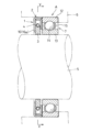
- FIG. 1 is a cross-sectional view showing a first embodiment of a bearing unit using a current-carrying unit according to the present invention
- 2 is a cross-sectional view taken along line II-II in FIG.
- FIG. 2 is an exploded perspective view of the energizing unit shown in FIG. 1
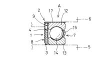
- FIG. 11 is a cross-sectional view showing a second embodiment of a bearing unit using a current-carrying unit according to the present invention.
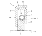
- 5 is a cross-sectional view taken along line VV in FIG. 5 is a cross-sectional view of a main part of the energizing unit shown in FIG.
- FIG. 5 is an exploded perspective view of the energizing unit shown in FIG. FIG.
- FIG. 5 is a cross-sectional view of a main part of a first modified example of the energizing unit shown in FIG.
- FIG. 5 is a cross-sectional view of a main part of a second modified example of the energizing unit shown in FIG.
- FIG. 5 is a cross-sectional view of a main part of a third modified example of the energizing unit shown in FIG.
- FIG. 5 is a cross-sectional view of a modified example of the bearing unit shown in FIG.
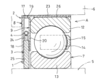
- FIG. 11 is a cross-sectional view showing a third embodiment of a bearing unit (current-carrying unit) according to the present invention.
- 13 is a cross-sectional view taken along line XIII-XIII in FIG. 12.
- FIG. 13 is an enlarged cross-sectional view of the bearing unit (current-carrying unit) shown in FIG.
- FIG. 13 is an exploded perspective view of the energizing unit shown in FIG. 12 .
- FIG. 13 is a cross-sectional view showing a modified example of the bearing unit (current-carrying unit) shown in FIG.
- FIG. 13 is a cross-sectional view showing a further modified example of the bearing unit (current-carrying unit) shown in FIG.
- FIG. 11 is a cross-sectional view showing a fourth embodiment of a bearing unit (current-carrying unit) according to the present invention.
- FIG. 13 is a cross-sectional view showing a fifth embodiment of a bearing unit (current-carrying unit) according to the present invention.
- the drawings show a bearing unit A that employs a current-carrying unit 1 according to the present invention.
- the current-carrying unit 1 has a case body 2, a current-carrying member 3, and a radial elastic member 4 as its main components.
- This current-carrying unit 1 is provided between a motor shaft 5 of an e-axle or the like and a housing 6, adjacent to a bearing 7 (a ball bearing in this embodiment) that is interposed between the motor shaft 5 and the housing 6 and supports the motor shaft 5.
- the housing 6 is electrically grounded.
- the current-carrying unit 1 and the bearing 7 in axial contact as shown in FIG. 1, but a configuration in which a gap is provided between the two is also acceptable.
- the direction along the rotation axis of the motor shaft 5 is referred to as the axial direction
- the direction perpendicular to the rotation axis is referred to as the radial direction
- the direction along the circumference going around the rotation axis is referred to as the circumferential direction.
- the case body 2 is a conductive annular member that is fitted into the inner diameter surface of the housing 6.
- This case body 2 is composed of an annular outer ring 8 having a flange extending in one axial direction on its outer periphery, and a retainer 9 having a flange extending in another axial direction opposite to the one axial direction on its outer periphery.
- the flange formed on the outer ring 8 and the flange formed on the retainer 9 are integrated by press-fitting. Note that maintainability can also be improved by inserting the flange formed on the retainer 9 into the flange formed on the outer ring 8, and then fixing the outer ring 8 and the retainer 9 with a stop ring on the width surface.
- the outer ring portion 8 and the retainer 9 are both made of steel.
- An axial gap capable of accommodating the current-carrying member 3 and the radially elastic member 4 is formed between the engaged outer ring portion 8 and the retainer 9.
- the retainer 9 has multiple (four in this embodiment) bent portions 10 formed at predetermined angular intervals, extending from its inner edge in the other axial direction (the same direction as the flange formed on the retainer 9).
- the conductive member 3 is a conductive arc-shaped member that protrudes radially inward from the case body 2 and slides against the motor shaft 5 supported by the bearing 7.
- the conductive members 3 are housed one by one between adjacent bent portions 10 formed in the retainer 9 in the circumferential direction. In this embodiment, four conductive members 3 are arranged at equal intervals in the circumferential direction. The number of conductive members 3 can be changed as appropriate, but it is preferable to have multiple conductive members.
- the number of bent portions 10 formed in the retainer 9 is determined according to the number of conductive members 3. In this embodiment, polytetrafluoroethylene (PTFE) with added carbon is used as the material for the conductive members 3.
- the inner diameter surface of the conductive member 3 is composed of a part of a cylindrical surface and is in surface contact with the outer circumferential surface of the motor shaft 5. An outer circumferential groove 11 is formed on the outer circumferential edge of the conductive member 3.
- the material for the conductive member 3 can be metal, carbon, or conductive resin such as carbon-added polyether ether ketone (PEEK), rubber, ceramics, or a composite of these.
- PEEK carbon-added polyether ether ketone
- the surface of the conductive member 3 (particularly the inner diameter surface that comes into sliding contact with the motor shaft 5) can be treated with a coating (e.g., a conductive diamond-like carbon (DLC) film, a metal film (plating layer, etc.)) that improves electrical conductivity and wear resistance.
- DLC conductive diamond-like carbon
- the radial elastic member 4 is a member for biasing the current-carrying members 3 radially inward toward the motor shaft 5 (see the arrow in FIG. 2). As shown in FIG. 2, the radial elastic member 4 is hung across the outer circumferential groove 11 formed on the outer circumferential edge of each current-carrying member 3.
- a garter spring made of a coiled steel wire processed into a ring shape is used as the radial elastic member 4, but it is also possible to use, for example, a circlip (C-shaped retaining ring) with a slit in part of the ring or annular rubber.
- a single radial elastic member 4 biases all the current-carrying members 3, but it is also possible to provide a radial elastic member 4 for each current-carrying member 3 individually.
- this current-carrying unit 1 The function of this current-carrying unit 1 will now be described.
- the motor shaft 5 is inserted into the axis of this current-carrying unit 1.
- the motor shaft 5 comes into sliding contact with the inner diameter surface of the current-carrying member 3, which is biased toward the motor shaft 5 by the biasing force of the radial elastic member 4, and this inner diameter surface gradually wears. Even if wear occurs in this way, the current-carrying member 3 is always biased toward the motor shaft 5 by the radial elastic member 4, so the contact state (current-carrying state) between the motor shaft 5 and the current-carrying member 3 is maintained.
- the conductive member 3 is in contact with the case body 2 (at least one of the outer ring portion 8 or the retainer 9), and a current circuit is formed as a bypass path between the motor shaft 5, the conductive member 3, the case body 2, and the housing 6.
- a current circuit is formed as a bypass path between the motor shaft 5, the conductive member 3, the case body 2, and the housing 6.
- the above-mentioned current-carrying unit 1 allows the electric charge generated on the motor shaft 5 to escape to the housing 6 via the current-carrying member 3 and the case main body 2, thereby preventing electrolytic corrosion of the bearing 7 provided between the motor shaft 5 and the housing 6. Furthermore, since the current-carrying member 3 is biased radially inward, i.e., toward the motor shaft 5, by the radial elastic member 4, even if the current-carrying member 3 wears over time, the contact state between the motor shaft 5 and the current-carrying member 3 is maintained, and the electrolytic corrosion prevention effect can be maintained over a long period of time.
- the current-carrying member 3 has an initial radial width that is sufficient to withstand long-term use even if it wears over time.
- the above-mentioned current-carrying unit 1 ensures a wide current-carrying area by bringing the inner diameter surface of the current-carrying member 3 into surface contact with the outer circumference of the motor shaft 5, so that the amount of current that escapes from the motor shaft 5 to the housing 6 via the current-carrying unit 1 can be increased, and electrical corrosion of the bearing 7 can be more effectively prevented.
- the above current-carrying unit 1 can reliably exert the electrolytic corrosion prevention effect, since even if a problem occurs that impairs the electrical conduction of some of the current-carrying members 3, the electrical conduction effect of the other current-carrying members 3 can be ensured. Furthermore, the aligning function of the multiple current-carrying members 3 can stabilize the contact state between the motor shaft 5 and each current-carrying member 3, thereby further improving the electrolytic corrosion prevention effect.
- the motor shaft 5 is inserted through the axis of the current-carrying unit 1, and the current-carrying member 3 is biased radially inward by the radial elastic member 4 to slide against the motor shaft 5.
- the motor shaft 5 is provided on the outer diameter side of the current-carrying unit 1 and the housing 6 is provided on the inner diameter side of the current-carrying unit 1, the current-carrying member 3 can be biased radially outward by the radial elastic member 4.
- the current-carrying unit 1 and the bearing 7 that make up the bearing unit A are separate members.
- the flange of the outer ring portion 8 of the current-carrying unit 1 can be extended in the axial direction toward the outer ring of the bearing 7, so that the current-carrying unit 1 and the bearing 7 are integrated into one unit.
- FIG. 4 A second embodiment of a bearing unit A employing a current-carrying unit 1 according to the present invention is shown in Figure 4.
- the bearing unit A is composed of a current-carrying unit 1 and a bearing 7 (a ball bearing in this embodiment).
- the bearing 7 has an outer ring 12, an inner ring 13 arranged on the inner diameter side of the outer ring 12, rolling elements 14 provided between the outer ring 12 and the inner ring 13, and a retainer 15 that holds the rolling elements 14 at a predetermined interval in the circumferential direction.
- the current-carrying unit 1 and the outer ring 12 of the bearing 7 abut against each other.
- this current-carrying unit 1 As shown in Figures 4 to 7, the main components of this current-carrying unit 1 are a case main body 2, a current-carrying member 3, a radial elastic member 4, and a pressing mechanism 16.
- This current-carrying unit 1 is interposed between a motor shaft 5 of an e-axle or the like and a housing 6, and is disposed adjacent to a bearing 7 that supports the motor shaft 5.
- the housing 6 is electrically grounded.
- the direction along the rotation axis of the motor shaft 5 is referred to as the axial direction
- the direction perpendicular to the rotation axis as the radial direction
- the direction along the circumference going around the rotation axis as the circumferential direction.
- the case body 2 is a conductive annular member fitted into the housing 6.
- the case body 2 has an annular outer ring 8 having a flange 17 extending in one axial direction at the outer periphery and an extension piece 18 extending radially inward from the outer periphery, and an annular retainer 9 having a flange 19 extending in another axial direction opposite to the one axial direction at the outer periphery and an extension piece 20 extending radially inward from the outer periphery.
- the flange 17 formed on the outer ring 8 and the flange 19 formed on the retainer 9 are integrated by press-fitting.
- a circumferential groove opening toward the inner diameter side is formed by the flanges 17, 19 and the extension pieces 18, 20 formed on the outer ring 8 and the retainer 9, respectively.
- the flange 19 formed on the retainer 9 is inserted into the flange 17 formed on the outer ring 8, and then a stop ring is provided on the width surface to fix the outer ring 8 and the retainer 9, thereby improving maintainability.
- the outer ring portion 8 and the retainer 9 are both made of steel.
- the size of the axial gap of the circumferential groove formed by integrating the outer ring portion 8 and the retainer 9 is made slightly larger than the axial width of the current-carrying member 3 so that the current-carrying member 3 can move freely in the radial direction.
- the retainer 9 has multiple (four in this embodiment) bent portions 10 formed at predetermined angular intervals that extend from the inner edge of the extension piece 20 in the other axial direction (the same direction as the flange 19 formed on the retainer 9).
- the current-carrying member 3 is a conductive arc-shaped member that is provided in the circumferential groove and protrudes radially inward from the case body 2 to slide against the motor shaft 5.
- the current-carrying members 3 are housed one by one between adjacent circumferentially adjacent bent portions 10 formed in the retainer 9. In this embodiment, four current-carrying members 3 are arranged at equal intervals in the circumferential direction.
- the number of current-carrying members 3 can be changed as appropriate, but it is preferable to have multiple current-carrying members 3.
- the number of bent portions 10 formed in the retainer 9 is determined according to the number of current-carrying members 3.
- polytetrafluoroethylene (PTFE) with added carbon is used as the material for the current-carrying member 3.
- the inner diameter surface of the current-carrying member 3 is composed of a part of a cylindrical surface and is in surface contact with the outer circumferential surface of the motor shaft 5.
- An outer circumferential groove 11 is formed on the outer periphery of the current-carrying member 3.
- the material for the current-carrying member 3 can be a conductive material made of metal, carbon, or conductive resin such as carbon-added polyether ether ketone (PEEK), rubber, ceramics, or a composite of these.
- PEEK carbon-added polyether ether ketone
- the surface of the current-carrying member 3 (particularly the inner diameter surface that comes into sliding contact with the motor shaft 5) can be treated with a coating (e.g., a conductive diamond-like carbon (DLC) film, a metal film (plating layer, etc.)) that improves electrical conductivity and wear resistance.
- DLC conductive diamond-like carbon
- the radial elastic member 4 is provided in the circumferential groove and biases the current-carrying members 3 radially inward (see the arrow in FIG. 5). As shown in FIG. 5, the radial elastic member 4 is hung across the outer circumferential groove 11 formed in each current-carrying member 3.
- a garter spring made of a coiled steel wire processed into a ring shape is used as the radial elastic member 4, but it is also possible to use, for example, a circlip (C-shaped retaining ring) with a slit in part of the ring or annular rubber.
- a single radial elastic member 4 biases all the current-carrying members 3, but it is also possible to provide a radial elastic member 4 for each current-carrying member 3 individually.
- the pressing mechanism 16 is a mechanism for pressing the current-carrying member 3 from one axial side to the other.
- the pressing mechanism 16 is a bent portion 16a formed on at least one of the pair of walls (the outer ring portion 8 and the extension pieces 18, 20 of the retainer 9) that form the circumferential groove, which is bent toward the inside of the circumferential groove on the inner diameter side relative to the outer diameter side. More specifically, the bent portion 16a is formed by inclining the entire extension piece 18 of the outer ring portion 8 by a predetermined angle in the radial direction toward the inside of the circumferential groove, starting from the connection point with the flange 17. Note that the bent portion 16a may be formed only on the retainer 9, or may be formed on both the outer ring portion 8 and the retainer 9.
- this current-carrying unit 1 The function of this current-carrying unit 1 will now be described.
- the motor shaft 5 is inserted into the axis of this current-carrying unit 1.
- the motor shaft 5 comes into sliding contact with the inner diameter surface of the current-carrying member 3, which is biased toward the motor shaft 5 by the biasing force of the radial elastic member 4, and this inner diameter surface gradually wears. Even if wear occurs in this way, the current-carrying member 3 is always biased toward the motor shaft 5 by the radial elastic member 4, so the contact state (current-carrying state) between the motor shaft 5 and the current-carrying member 3 is maintained.
- the current-carrying member 3 is pressed against the retainer 9 by the pressing mechanism 16 (bent portion 16a formed on the extension piece 18 of the outer ring portion 8). This eliminates the axial gap between the current-carrying member 3 and the case body portion 2 (outer ring portion 8 and retainer 9), and a current-carrying circuit is formed as a bypass path between the motor shaft 5, the current-carrying member 3, the case body portion 2, and the housing 6. By forming a current-carrying circuit in this manner, the current passing through the bearing 7 interposed between the motor shaft 5 and the housing 6 is reduced, preventing electrolytic corrosion of the components of the bearing 7.
- the above-mentioned current-carrying unit 1 and bearing unit A allow the electric charge generated on the motor shaft 5 to escape to the housing 6 via the current-carrying member 3 and the case main body 2, thereby preventing electrolytic corrosion of the bearing 7 provided between the motor shaft 5 and the housing 6. Furthermore, since the current-carrying member 3 is biased radially inward, i.e., toward the motor shaft 5, by the radial elastic member 4, even if the current-carrying member 3 wears over time, the contact state between the motor shaft 5 and the current-carrying member 3 is maintained, and the electrolytic corrosion prevention effect can be maintained over a long period of time. It is preferable to use a current-carrying member 3 with an initial radial width that can withstand long-term use even if it wears over time.
- the above-mentioned current-carrying unit 1 and bearing unit A are configured so that the bending portion 16a serving as the pressing mechanism 16 presses the current-carrying member 3 from one side to the other in the axial direction, so that the current-carrying member 3 can be kept in contact with the case main body 2, and stable current-carrying performance can be achieved.
- the above-mentioned current-carrying unit 1 and bearing unit A ensure a wide current-carrying area by bringing the inner diameter surface of the current-carrying member 3 into surface contact with the outer circumference of the motor shaft 5, so that the amount of current that escapes from the motor shaft 5 to the housing 6 via the current-carrying unit 1 can be increased, and electrical corrosion of the bearing 7 can be more effectively prevented.
- the above-mentioned current-carrying unit 1 and bearing unit A can reliably exert the electrolytic corrosion prevention effect, since even if a problem occurs that impairs the electrical conduction of some of the current-carrying members 3, the electrical conduction of the other current-carrying members 3 can be ensured. Furthermore, the aligning function of the multiple current-carrying members 3 can stabilize the contact state between the motor shaft 5 and each current-carrying member 3, thereby further improving the electrolytic corrosion prevention effect.
- the first modified example of the current-carrying unit 1 is shown in FIG. 8.
- the current-carrying unit 1 according to the first modified example has the same basic configuration as the current-carrying unit 1 shown in FIG. 4 and the like, but differs in that the bent portion 16a as the pressing mechanism 16 is formed only on a part of the inner diameter tip of the extension piece 18 of the outer ring portion 8. Even in this configuration, the bent portion 16a can press the current-carrying member 3 from one side in the axial direction to the other side, so that the contact state between the current-carrying member 3 and the case main body portion 2 can be maintained, and stable current-carrying performance can be exhibited. Note that, as with the current-carrying unit 1 shown in FIG. 4 and the like, the bent portion 16a can be formed only on the retainer 9, or on both the outer ring portion 8 and the retainer 9.
- the second modified example of the current-carrying unit 1 is shown in FIG. 9.
- the current-carrying unit 1 according to the second modified example has the same basic configuration as the current-carrying unit 1 shown in FIG. 4 and the like, but differs in that the pressing mechanism 16 is an axial elastic member 16b interposed in the axial gap between the inner surface of the circumferential groove and the current-carrying member 3. Even in this configuration, the current-carrying member 3 can be pressed from one side in the axial direction to the other side by the axial elastic member 16b, so that the contact state between the current-carrying member 3 and the case main body 2 (outer ring portion 8) can be maintained, and stable current-carrying performance can be exhibited.
- the axial elastic member 16b is interposed between the retainer 9 and the current-carrying member 3, but the axial elastic member 16b can also be interposed between the outer ring portion 8 and the current-carrying member 3.
- the axial elastic member 16b can be made of a conductive material such as metal, carbon, or a conductive resin, rubber, ceramics, or a composite of these.
- the third modified example of the current-carrying unit 1 is shown in FIG. 10.
- the current-carrying unit 1 according to the third modified example has the same basic configuration as the current-carrying unit 1 shown in FIG. 4 and the like, but differs in that the pressing mechanism 16 is an inclined surface portion 16c having a normal inclined to one side in the axial direction, formed at the contact portion between the current-carrying member 3 and the radial elastic member 4.
- the inclined surface portion 16c is inclined so as to approach the motor shaft 5 from the outer ring portion 8 side toward the retainer 9 side.
- the inclined surface portion 16c can also be inclined so that it approaches the motor shaft 5 as it moves from the retainer 9 side toward the outer ring portion 8 side.
- the radial elastic member 4 out of metal, as in the current-carrying unit 1 shown in FIG. 4.
- multiple current-carrying routes can be secured, including a current-carrying route in which current flows directly from the current-carrying member 3 to the case main body 2 (outer ring portion 8), and a current-carrying route in which current flows from the current-carrying member 3 to the case main body 2 (retainer 9) via the radial elastic member 4, thereby achieving more stable current-carrying performance.
- FIG. 11 A modified example of the bearing unit A is shown in FIG. 11.
- the bearing unit A according to this modification has the same basic structure as the bearing unit A shown in FIG. 4, but differs in that, whereas the current-carrying unit 1 and the bearing 7 are separate members in this bearing unit A, the flange 17 of the outer ring portion 8 of the current-carrying unit 1 shown in FIG. 4 and other figures is extended in the axial direction to the outer diameter side of the outer ring 12 of the bearing 7 to form the bearing unit A in which the current-carrying unit 1 and the bearing 7 are integrated. In this way, the same effects as those of the current-carrying unit 1 and the bearing unit A shown in FIG.
- the size of the bearing unit A can be made the same as the main dimensions of the bearing standardized in the Japanese Industrial Standards (JIS B1512-1:2011), making it possible to reduce the weight and width of the bearing unit A equipped with the current-carrying unit 1.
- the motor shaft 5 is inserted through the axis of the current-carrying unit 1, and the current-carrying member 3 is biased radially inward by the radial elastic member 4 to slide against the motor shaft 5.
- the motor shaft 5 is provided on the outer diameter side of the current-carrying unit 1 and the housing 6 is provided on the inner diameter side of the current-carrying unit 1, the current-carrying member 3 can be biased radially outward by the radial elastic member 4.
- the bearing unit A (current-carrying unit 1) according to the present invention will be described with reference to the drawings.
- the bearing unit A according to the third embodiment has a current-carrying unit 1 and a bearing 7, and is constructed by integrating the two.
- the bearing unit A is interposed between a motor shaft 5 of an e-axle or the like and a housing 6, and supports the motor shaft 5 so that it can rotate freely.
- the housing 6 is electrically grounded.
- the direction along the rotation axis of the motor shaft 5 is referred to as the axial direction
- the direction perpendicular to the rotation axis is referred to as the radial direction
- the direction along the circumference going around the rotation axis is referred to as the circumferential direction.
- the current-carrying unit 1 has a conductive annular case body 2, a conductive current-carrying member 3 that protrudes radially inward from the case body 2, and a radial elastic member 4 that biases the current-carrying member 3 radially inward.
- the case body 2 has an annular outer ring portion 8 having a flange 17 extending in one axial direction at the outer periphery and an extension piece 18 extending radially inward from the outer periphery, and an annular retainer 9 having a flange 19 extending in another axial direction opposite to the one axial direction at the outer periphery and an extension piece 20 extending radially inward from the outer periphery.
- a plurality of oil holes 21, 22 are formed in the outer ring portion 8 and the extension pieces 18, 20 of the retainer 9 at predetermined angular intervals in the circumferential direction (in this embodiment, four oil holes 21, 22 each at a 90 degree pitch).
- a bearing fitting portion 23 is extended in the one direction on the flange 17 of the outer ring portion 8.
- the flange 17 formed on the outer ring portion 8 and the flange 19 formed on the retainer 9 are integrated by press-fitting.
- the circumferential positions of the oil hole 21 formed on the outer ring portion 8 and the oil hole 22 formed on the retainer 9 are aligned.
- a circumferential groove that opens toward the inner diameter side is formed by the flanges 17, 19 and extension pieces 18, 20 formed on the outer ring portion 8 and the retainer 9, respectively.
- a stop ring can be provided on the width surface to fix the outer ring portion 8 and the retainer 9, thereby improving maintainability.
- the outer ring portion 8 and the retainer 9 are both made of steel.
- An axial gap capable of accommodating the current-carrying member 3 and the radially elastic member 4 is formed between the fitted outer ring portion 8 and the retainer 9.
- the retainer 9 has a plurality of bent portions 10 (four in this embodiment) formed at predetermined angular intervals, extending from its inner edge in the other axial direction (the same direction as the flange 19 formed in the retainer 9). Each bent portion 10 is formed corresponding to the circumferential center position of the oil hole 22 formed in the retainer 9.
- the current-carrying member 3 has a substantially arc-shaped base 24 and a current-carrying portion 25 that protrudes radially inward from the base 24, and is configured so that the current-carrying portion 25 slides against the motor shaft 5.
- the current-carrying members 3 are housed one by one between adjacent circumferentially adjacent bent portions 10 formed in the retainer 9. In this embodiment, four current-carrying members 3 are arranged at equal intervals in the circumferential direction.
- the number of current-carrying members 3 can be changed as appropriate, but it is preferable to have more than one.
- the number of bent portions 10 formed in the retainer 9 is determined according to the number of current-carrying members 3.
- polytetrafluoroethylene (PTFE) with added carbon is used as the material for the current-carrying portion 25.
- An outer peripheral groove 11 is formed on the outer peripheral edge of the base 24.
- the material for the current-carrying part 25 can be metal, carbon, or conductive resin such as polyetheretherketone (PEEK) with carbon added, rubber, ceramics, or a composite of these materials, ensuring the current-carrying performance of the current-carrying unit with a simple configuration.
- PEEK polyetheretherketone
- the surface of the current-carrying part 25 (particularly the part that comes into sliding contact with the motor shaft 5) can be treated with a coating (e.g., a conductive diamond-like carbon (DLC) film, a metal film (plating layer, etc.)) that improves current conduction and wear resistance.
- DLC conductive diamond-like carbon
- the radial elastic member 4 is a member for biasing the current-carrying members 3 radially inward toward the motor shaft 5 (see the arrow in FIG. 13). As shown in FIG. 13, the radial elastic member 4 is hung across the outer circumferential groove 11 formed on the outer circumferential edge of each current-carrying member 3.
- a garter spring made of a coiled steel wire processed into a ring shape is used as the radial elastic member 4, but it is also possible to use, for example, a circlip (C-shaped retaining ring) with a slit in part of the ring or annular rubber.
- a single radial elastic member 4 biases all the current-carrying members 3, but it is also possible to provide a radial elastic member 4 for each current-carrying member 3 individually.
- the bearing 7 is a ball bearing having an outer ring 12, an inner ring 13 arranged on the inner diameter side of the outer ring 12, rolling elements 14 provided between the outer ring 12 and the inner ring 13, and a retainer 15 that holds the rolling elements 14 at a predetermined interval in the circumferential direction.
- the bearing 7 according to this embodiment is not provided with a hermetic seal, and the axial flow of the lubricating oil inside the bearing unit A is ensured.
- the current-carrying unit 1 and the bearing 7 are integrated by the bearing fitting portion 23 formed on the outer ring portion 8 of the case main body 2 fitting into the outer diameter surface of the outer ring 12.
- Bearing unit A is designed so that the inner diameter, outer diameter, and axial width of bearing unit A when current-carrying unit 1 and bearing 7 are integrated match any combination of the main dimensions (bearing inner diameter d, bearing outer diameter D, bearing width B) of the bearing specified in Japanese Industrial Standard JIS B1512-1:2011.
- Motor shaft 5 is inserted into the axis of bearing unit A (current-carrying unit 1 and bearing 7).
- the motor shaft 5 comes into sliding contact with current-carrying part 25 of current-carrying member 3, which is biased toward motor shaft 5 by the biasing force of radial elastic member 4, the sliding portion of current-carrying part 25 with motor shaft 5 gradually wears out. Even if wear occurs in this way, the current-carrying member 3 (current-carrying part 25) is always biased toward motor shaft 5 by radial elastic member 4, so the contact state (current-carrying state) between motor shaft 5 and current-carrying member 3 is maintained.
- the current-carrying portion 25 is in contact with the case body 2 (at least one of the outer ring portion 8 or the retainer 9), and a current-carrying circuit is formed as a bypass path between the motor shaft 5, the current-carrying portion 25, the case body 2, and the housing 6.
- a current-carrying circuit By forming a current-carrying circuit in this way, the current passing through the bearing 7 interposed between the motor shaft 5 and the housing 6 is reduced.
- the above-mentioned bearing unit A has oil holes 21, 22 formed in the case body 2 that allow the flow of lubricating oil in the axial direction, which improves the axial flow of the lubricating oil inside the bearing unit A when used in an oil bath, and by eliminating the need for a seal or labyrinth for the bearing 7, the bearing unit A can be made more compact while preventing electrolytic corrosion of the bearing 7.
- the bearing unit A can reliably exert an electrolytic corrosion prevention effect, since even if a problem occurs that impairs the electrical conduction of some of the current-carrying members 3, the electrical conduction of the other current-carrying members 3 can be ensured. Furthermore, the aligning function of the multiple current-carrying members 3 can stabilize the contact state between the motor shaft 5 and each current-carrying member 3, thereby further improving the electrolytic corrosion prevention effect.
- the bearing unit A described above is configured so that the inner diameter, outer diameter, and axial width when the current-carrying unit 1 and bearing 7 are integrated match any of the combinations of major dimensions of bearings specified in the Japanese Industrial Standard JIS B1512-1:2011, making it possible to directly replace bearings (standard bearings, base bearings) specified in the Japanese Industrial Standard with the bearing unit A according to the present invention.
- FIG. 16 A modified example of the bearing unit A (current-carrying unit 1) according to the third embodiment is shown in FIG. 16.
- the bearing unit A according to this modified example differs from the above configuration in that an insulating part 26 is formed on the inner surface (the surface facing the outer ring 12 of the bearing 7) of the bearing fitting part 23 formed on the outer ring part 8.
- an insulating part 26 is formed on the inner surface (the surface facing the outer ring 12 of the bearing 7) of the bearing fitting part 23 formed on the outer ring part 8.
- FIG. 18 A fourth embodiment of the bearing unit A (current-carrying unit 1) according to the present invention is shown in FIG. 18.
- the bearing unit A according to the fourth embodiment is similar to the bearing unit A according to the third embodiment in that the bearing fitting portion 23 formed on the outer ring portion 8 of the case body 2 fits into the outer diameter surface of the outer ring 12, thereby integrating the current-carrying unit 1 and the bearing 7.
- it differs in that the axial length of one of a pair of groove shoulders formed on the outer diameter surface of the inner ring 13 is longer than the other, and the current-carrying member 3 (current-carrying portion 25) is in sliding contact with this one groove shoulder (the outer diameter surface of the inner ring 13).
- a current circuit is formed as a bypass path between the motor shaft 5, inner ring 13, current-carrying portion 25, case body 2, and housing 6.
- FIG. 19 A fifth embodiment of the bearing unit A (current-carrying unit 1) according to the present invention is shown in FIG. 19.
- the bearing unit A according to the fifth embodiment is similar to the bearing unit A according to the third embodiment in that the current-carrying member 3 (current-carrying portion 25) is biased by the radial elastic member 4 so as to come into sliding contact with the motor shaft 5 inserted through the axis of the inner ring 13.
- the axial length of one of a pair of groove shoulders formed on the inner diameter surface of the outer ring 12 is longer than the other, and the outer periphery of the case main body 2 is fitted into this one groove shoulder (the inner diameter surface of the outer ring 12).
- an electrical circuit is formed as a bypass path between the motor shaft 5, the electrical current section 25, the case main body 2, the outer ring 12, and the housing 6.
- the motor shaft 5 is inserted through the axis of the bearing unit A, and the current-carrying member 3 is biased radially inward by the radial elastic member 4, causing the current-carrying portion 25 to slide against the outer diameter surface of the motor shaft 5 or the inner ring 13.
- the current-carrying member 3 can be biased radially outward by the radial elastic member 4.
Landscapes
- Engineering & Computer Science (AREA)
- General Engineering & Computer Science (AREA)
- Mechanical Engineering (AREA)
- Rolling Contact Bearings (AREA)
- Support Of The Bearing (AREA)
Abstract
通電ユニット(1)を、内径側に向かって開口する周溝が形成された、導電性を有する環状のケース本体部(2)と、前記周溝内に設けられ、ケース本体部(2)から径方向内向きに突出する導電性を有する通電部材(3)と、前記周溝内に設けられ、通電部材(3)を径方向内向きに付勢する径方向弾性部材(4)と、を有する構成とする。
Description
この発明は、モータ軸などの回転軸を支持する軸受に併設される通電ユニット、および、この通電ユニットを採用した軸受ユニットに関する。
モータ軸などの回転軸を支持する軸受として、転がり軸受、特に玉軸受が一般的に用いられている。近年、モータを効率的に運転するため、インバータ制御が一般的に採用されている。特に車載用モータの場合は、車両への搭載性の点から小型化が図られており、その小型化されたモータをより効率的に使用するため、より細かな制御が行われている。
このモータ軸には、軸電流や軸電圧が生じることが分かっている。この電流が軸受内部を通過すると、金属からなる軌道輪や転動体に電食が生じることがある。そこで、例えば下記特許文献1においては、モータ12のシャフト16にフィラメント30(接地ブラシ)を接触させ、フィラメント30を介してシャフト16に生じた電荷をハウジングに逃がし、電流が軸受内部を通過しないようにしている(特許文献1のFig.2などを参照)。また、下記特許文献2においては、軸68に放出体8(領域10)を接触させ、放出体8を介して軸68に生じた電荷をハウジング69に逃がし、電流が軸受内部を通過しないようにしている(特許文献2のFig.24などを参照)。
また、例えば下記特許文献3においては、モータ軸を支持する軸受1内に通電ブラシ32を収納し、通電ブラシ32をバネ31で付勢することによって、通電ブラシ32が摩耗した場合であっても所定の通電性能を確保している。
特許文献1、2に示す構成は、モータ軸(シャフト16、軸68)に摺接部材(フィラメント30、放出体8)を摺接させて電荷を逃がすようにしているため、経時的な摺接部材の摩耗や変形などによって通電性能が低下し、電食防止効果が不十分となるおそれがある。
また、特許文献3に示す構成は、ドライ環境での使用を前提としており、軸受1や通電ブラシ32に密封のためのシール7やラビリンス隙間Sが設けられている。このため、油浴中での使用に際して軸方向への潤滑油の流動が阻害されるとともに、軸受ユニット(軸受1)を取り付けるための広いスペースを確保する必要があり、使用条件や取り付け条件が制約される問題がある。
本発明が解決しようとする課題は、電食防止効果を長期間に亘って維持することが可能な通電ユニットおよび軸受ユニットを提供することを第一の課題とし、油浴中での使用に好適でかつコンパクトな、通電ユニットおよび電食防止作用を有する軸受ユニットを提供することを第二の課題とする。
上記第一の課題を解決するため、本発明では、
内径側に向かって開口する周溝が形成された、導電性を有する環状のケース本体部と、
前記周溝内に設けられ、前記ケース本体部から径方向内向きに突出する導電性を有する通電部材と、
前記周溝内に設けられ、前記通電部材を径方向内向きに付勢する径方向弾性部材と、
を有する通電ユニットを構成(第1構成)した。
内径側に向かって開口する周溝が形成された、導電性を有する環状のケース本体部と、
前記周溝内に設けられ、前記ケース本体部から径方向内向きに突出する導電性を有する通電部材と、
前記周溝内に設けられ、前記通電部材を径方向内向きに付勢する径方向弾性部材と、
を有する通電ユニットを構成(第1構成)した。
このようにすると、モータ軸からハウジングに電流を通すバイパス経路が新たに形成され、モータ軸とハウジングとの間に設けられた軸受の電食を防止することができる。しかも、径方向弾性部材によって通電部材をモータ軸に向かって付勢するようにしたので、経時的に通電部材が摩耗したとしても、モータ軸と通電部材の接触状態が保たれ、長期間に亘って電食防止効果を維持することができる。
第1構成においては、前記周溝内において前記通電部材を軸方向の一方側から他方側に向かって押し付ける押し付け機構を有する構成(第2構成)とするのが好ましい。
このようにすると、押し付け機構によって通電部材が軸方向の一方側から他方側に向かって押し付けられるため、通電部材とケース本体部との接触状態を保つことができ、安定的な通電性能を発揮させることができる。
第2構成においては、前記押し付け機構が、前記周溝を構成する一対の壁部の少なくとも一方に形成された、外径側に対し内径側で前記周溝の内側に向かって屈曲する屈曲部である構成(第3構成)、または、前記周溝の内面と前記通電部材との間の軸方向隙間に介在する軸方向弾性部材である構成(第4構成)、とするのが好ましい。これらの構成によると、通電部材を軸方向の一方側から他方側に向かって押し付けることができ、通電部材とケース本体部の接触状態を確実に保つことができる。
また、第1構成においては、上記第二の課題を解決するために、前記ケース本体部に、軸方向への潤滑油の流動を許容する油孔が形成されている構成(第5構成)とするのが好ましい。このようにすると、この通電ユニットと組み合わせて用いられる軸受を油浴中で使用するのに際して、軸受内部における潤滑油の軸方向への流動性を向上することができるとともにこの軸受の電食を防止することができる。
第5構成においては、前記ケース本体部が、軸方向に延設された軸受嵌合部を有する構成(第6構成)とするのが好ましい。このようにすると、通電ユニットと、この通電ユニットと組み合わせて用いられる軸受とを容易に一体化することができる。
第6構成においては、前記軸受嵌合部の径方向内側面、または、前記ケース本体部の前記軸受嵌合部の延設方向に臨む面の少なくとも一方に絶縁部が設けられている構成(第7構成)とするのが好ましい。このようにすると、ケース本体部とこの通電ユニットと組み合わせて用いられる軸受との間で電流が流れるのを阻止することができ、軸受の電食をより確実に防止することができる。
前記絶縁部は、絶縁性が高い材質で構成されることが望ましい。このような材質としては、例えば、各種セラミックスや各種樹脂が挙げられるが、絶縁抵抗、絶縁破壊電圧、機械的強度、加工性などの点から、各種セラミックス、ポリフェニレンサルファイド樹脂、ポリアミドイミド樹脂、およびエポキシ樹脂の中の少なくとも一つを含有する焼成膜が好ましい。
第1構成から第7構成においては、前記通電部材が複数設けられている構成(第8構成)とするのが好ましい。このようにすると、一部の通電部材の通電性能が損なわれたとしても、他の通電部材でカバーすることができるため、安定的な通電性能を確保することができる。
第8構成においては、前記ケース本体部が、環状の外環部と、前記外環部に嵌合するリテナと、を有し、前記リテナに、複数の前記通電部材を周方向に等間隔で配置する複数の折り曲げ部が形成されている構成(第9構成)とするのが好ましい。このようにすると、複数の折り曲げ部の間にそれぞれ収納された通電部材を径方向弾性部材で径方向内向きに付勢することによる調心機能が発揮され、モータ軸と通電部材との間の接触状態を安定させることができる。
また、本発明においては、
第1構成から第9構成に係る通電ユニットと、外輪と、前記外輪の内径側に配置された内輪と、前記外輪と前記内輪との間に設けられた転動体と、前記転動体を周方向に所定間隔で保持する保持器と、を有する軸受と、を有し、前記通電ユニットが前記軸受に嵌合することで両者が一体化されている軸受ユニットを構成(第10構成)した。
第1構成から第9構成に係る通電ユニットと、外輪と、前記外輪の内径側に配置された内輪と、前記外輪と前記内輪との間に設けられた転動体と、前記転動体を周方向に所定間隔で保持する保持器と、を有する軸受と、を有し、前記通電ユニットが前記軸受に嵌合することで両者が一体化されている軸受ユニットを構成(第10構成)した。
特に、第5構成から第7構成においては、油浴中での使用に際して、軸受ユニット内部における潤滑油の軸方向への流動性を向上することができるとともに、軸受の密封シールやラビリンスを不要とすることで軸受ユニットをコンパクト化しつつ、軸受の電食を防止することができる。
第10構成においては、前記外輪が前記通電ユニットに当接するように配置された構成(第11構成)とするのが好ましい。また、第11構成においては、前記外輪の端面が前記通電ユニットに当接するように配置された構成(第12構成)とするのが好ましい。
また、第10構成においては、前記ケース本体部の外周が、前記外輪の内径面に嵌合しており、前記通電部材が、前記内輪の軸心に挿通されたモータ軸に摺接するように付勢されている構成(第13構成)とするのが好ましい。
また、通電ユニットを、第6構成または第7構成に係る通電ユニットと、外輪と、前記外輪の内径側に配置された内輪と、前記外輪と前記内輪との間に設けられた転動体と、前記転動体を周方向に所定間隔で保持する保持器と、を有する軸受と、を有し、前記軸受嵌合部が前記外輪の外径面に嵌合し、前記通電部材が、前記内輪の軸心に挿通されたモータ軸、または、前記内輪の外径面に摺接するように付勢されている構成(第14構成)とすることもできる。このようにすると、通電ユニットと軸受を容易に一体化することができる。また、通電部材を内輪の外径面に摺接させてモータ軸に直接摺動しないようにすると、モータ軸を所定の表面粗さや硬度とするための特別な加工や工法を行う必要がなく、コストの削減を図ることができる可能性がある。
また、通電ユニットを、第7構成に係る通電ユニットと、外輪と、前記外輪の内径側に配置された内輪と、前記外輪と前記内輪との間に設けられた転動体と、前記転動体を周方向に所定間隔で保持する保持器と、を有する軸受と、を有し、前記絶縁部が、前記外輪の外径面または端面の少なくとも一方と接触している構成(第15構成)とすることもできる。このようにすると、ケース本体部と外輪との間で電流が流れるのを阻止することができ、軸受の電食をより確実に防止することができる。
本発明の通電ユニットによると、モータ軸からハウジングに電流を通すバイパス経路が新たに形成されるため、モータ軸とハウジングとの間に設けられた軸受の電食を防止することができる。しかも、弾性部材によって通電部材をモータ軸に向かって付勢するようにしたので、経時的に通電部材が摩耗したとしても、モータ軸と通電部材の接触状態が保たれ、長期間に亘って軸受ユニットの電食防止効果を維持することができる。また、ケース本体部に軸方向への潤滑油の流動を許容する油孔を形成することにより、油浴中での使用に際して、軸受ユニット内部における潤滑油の軸方向への流動性を向上することができるとともに、軸受の密封シールやラビリンスを不要とすることで軸受ユニットをコンパクト化しつつ、軸受の電食を防止することができる。
本発明に係る通電ユニット1を採用した軸受ユニットAを図面に示す。図1から図3に示すように、通電ユニット1は、ケース本体部2と、通電部材3と、径方向弾性部材4と、を主要な構成要素としている。この通電ユニット1は、eアクスルなどのモータ軸5とハウジング6との間に介在してこのモータ軸5を支持する軸受7(この実施形態では玉軸受)と隣り合うように、モータ軸5とハウジング6の間に介在して設けられている。ハウジング6は、電気的に接地されている。
電食防止効果の観点からは、図1に示すように、通電ユニット1と軸受7を軸方向に接触して設けるのが好ましいが、両者の間に隙間が設けられた構成も許容される。以下においては、モータ軸5の回転軸に沿う方向を軸方向、前記回転軸に対して垂直な方向を径方向、前記回転軸周りに一周する円周に沿う方向を周方向と称する。
ケース本体部2は、ハウジング6の内径面に嵌め込まれる導電性を有する環状の部材である。このケース本体部2は、外周縁に軸方向の一方向に延びるフランジを有する環状の外環部8と、外周縁に軸方向の前記一方向と逆向きの他方向に延びるフランジを有するリテナ9から構成されている。図1に示すように、外環部8に形成されたフランジと、リテナ9に形成されたフランジは、圧入固定によって一体化される。なお、外環部8に形成されたフランジに、リテナ9に形成されたフランジを挿入した後に、幅面に止め輪を設けて外環部8とリテナ9を固定することによって、メンテナンス性の向上を図ることもできる。
外環部8とリテナ9は、いずれも鋼材から構成されている。嵌合した外環部8とリテナ9の間には、通電部材3と径方向弾性部材4を収容可能な軸方向隙間が形成されている。リテナ9には、その内縁から軸方向の前記他方向(リテナ9に形成されたフランジと同じ方向)に延びる複数(この実施形態では4か所)の折り曲げ部10が所定の角度間隔で形成されている。
通電部材3は、ケース本体部2から径方向内向きに突出して、軸受7によって支持されたモータ軸5に摺接する導電性を有する円弧状の部材である。通電部材3は、リテナ9に形成された周方向に隣り合う折り曲げ部10の間に1個ずつ収容されている。この実施形態においては、4個の通電部材3が周方向に等間隔で配置されている。通電部材3の個数は適宜変更することができるが、複数個とするのが好ましい。リテナ9に形成される折り曲げ部10の数は、通電部材3の個数に対応して決定される。この実施形態では、通電部材3の素材として、カーボンが添加されたポリテトラフルオロエチレン(PTFE)を採用している。通電部材3の内径面は円筒面の一部から構成されており、モータ軸5の外周面と面接触している。通電部材3の外周縁には外周溝11が形成されている。
通電部材3の素材として、カーボンが添加されたPTFEの他に、金属、カーボン、または、カーボンが添加されたポリエーテルエーテルケトン(PEEK)などの導電性を付与した樹脂、ゴム、セラミックス、もしくは、これらの複合材を採用することもできる。また、通電部材3の表面(特にモータ軸5と摺接する内径面)に、通電性や耐摩耗性を向上させるコーティング(例えば、導電性を有するダイヤモンドライクカーボン(DLC)皮膜、金属皮膜(めっき層など))などの表面加工を施すこともできる。
径方向弾性部材4は、通電部材3をモータ軸5に向かって径方向内向きに付勢(図2中の矢印を参照)するための部材である。この径方向弾性部材4は、図2に示すように、各通電部材3の外周縁に形成された外周溝11に跨るように掛け渡されている。この実施形態では、径方向弾性部材4としてコイル状とした鋼線をリング状に加工したガータスプリングを用いたが、例えば、円環の一部に切れ目を有するサークリップ(C型止め輪)や環状のゴムなどを採用することもできる。なお、この実施形態においては、1個の径方向弾性部材4ですべての通電部材3を付勢する構成としたが、各通電部材3に個別に径方向弾性部材4を設けた構成とすることもできる。
この通電ユニット1の作用について説明する。この通電ユニット1の軸心にはモータ軸5が挿通される。モータ軸5の回転に伴って、モータ軸5と、径方向弾性部材4の付勢力によってモータ軸5に向かって付勢された通電部材3の内径面が摺接すると、この内径面が次第に摩耗する。このように摩耗が生じても、通電部材3は常に径方向弾性部材4によってモータ軸5に向かって付勢されているため、モータ軸5と通電部材3との間の接触状態(通電状態)が保たれる。
通電部材3は、ケース本体部2(外環部8またはリテナ9の少なくとも一方)に接触しており、モータ軸5、通電部材3、ケース本体部2、および、ハウジング6の間に、バイパス路としての通電回路が形成される。このように通電回路が形成されることにより、モータ軸5とハウジング6との間に介在する軸受7を経由する電流が減少し、軸受7の構成部材の電食が防止される。
上記の通電ユニット1は、モータ軸5に生じた電荷を通電部材3およびケース本体部2を介してハウジング6に逃がすようにしたので、モータ軸5とハウジング6との間に設けられた軸受7の電食を防止することができる。しかも、径方向弾性部材4によって通電部材3を径方向内向き、すなわち、モータ軸5に向かって付勢したので、経時的に通電部材3が摩耗したとしても、モータ軸5と通電部材3の接触状態が保たれ、長期間に亘って電食防止効果を維持することができる。なお、通電部材3は、経時的に摩耗が生じた場合でも長期の使用に耐え得る程度の初期径方向幅のものが用いられる。
また、上記の通電ユニット1は、通電部材3の内径面とモータ軸5の外周面を面接触させて広い通電面積を確保したので、通電ユニット1を経由してモータ軸5からハウジング6に逃がす電流量を増やすことができ、軸受7の電食をより効果的に防止することができる。
また、上記の通電ユニット1は、複数の通電部材3を設けたことにより、仮に一部の通電部材3の通電作用が損なわれるトラブルが生じても、他の通電部材3による通電作用を確保することができるため、電食防止効果を確実に発揮させることができる。また、複数の通電部材3による調心機能により、モータ軸5と各通電部材3の接触状態を安定させることができるため、電食防止効果をさらに向上させることができる。
なお、上記の実施形態においては、通電ユニット1の軸心にモータ軸5が挿通されており、通電部材3を径方向弾性部材4で径方向内向きに付勢することでモータ軸5に摺接させる構成としたが、これとは逆に、モータ軸5が通電ユニット1の外径側に、ハウジング6が通電ユニット1の内径側にそれぞれ設けられている場合は、通電部材3を径方向弾性部材4で径方向外向きに付勢する構成とすることもできる。
第一実施形態においては、図1に示したように、軸受ユニットAを構成する通電ユニット1と軸受7を別部材としたが、例えば、通電ユニット1の外環部8のフランジを軸受7の外輪に向かって軸方向に延設して、通電ユニット1と軸受7を一体化した構成とすることもできる。
本発明に係る通電ユニット1を採用した軸受ユニットAの第二実施形態を図4に示す。軸受ユニットAは、通電ユニット1と軸受7(この実施形態では玉軸受)から構成される。軸受7は、外輪12と、外輪12の内径側に配置された内輪13と、外輪12と内輪13との間に設けられた転動体14と、転動体14を周方向に所定間隔で保持する保持器15と、を有する。通電ユニット1と軸受7の外輪12は、互いに当接している。
図4から図7に示すように、この通電ユニット1は、ケース本体部2と、通電部材3と、径方向弾性部材4と、押し付け機構16と、を主要な構成要素としている。この通電ユニット1は、eアクスルなどのモータ軸5とハウジング6との間に介在して、モータ軸5を支持する軸受7と隣り合うように、モータ軸5とハウジング6の間に介在して設けられている。ハウジング6は、電気的に接地されている。以下においては、モータ軸5の回転軸に沿う方向を軸方向、前記回転軸に対して垂直な方向を径方向、前記回転軸周りに一周する円周に沿う方向を周方向と称する。
ケース本体部2は、ハウジング6に嵌め込まれる導電性を有する環状の部材である。ケース本体部2は、外周縁において軸方向の一方向に延びるフランジ17と外周縁から径方向内向きに延設された延設片18とを有する環状の外環部8と、外周縁において軸方向の前記一方向と逆向きの他方向に延びるフランジ19と外周縁から径方向内向きに延設された延設片20とを有する環状のリテナ9と、を有する。図4に示すように、外環部8に形成されたフランジ17と、リテナ9に形成されたフランジ19は、圧入固定によって一体化される。この一体化に伴い、外環部8およびリテナ9にそれぞれ形成されたフランジ17、19と延設片18、20によって、内径側に向かって開口する周溝が形成される。なお、外環部8に形成されたフランジ17に、リテナ9に形成されたフランジ19を挿入した後に、幅面に止め輪を設けて外環部8とリテナ9を固定することによって、メンテナンス性の向上を図ることもできる。
外環部8とリテナ9は、いずれも鋼材から構成されている。外環部8とリテナ9の一体化によって形成された周溝の軸方向隙間の大きさは、通電部材3が径方向に自在に移動できるように、通電部材3の軸方向幅よりもわずかに大きく形成されている。リテナ9には、その延設片20の内縁から軸方向の前記他方向(リテナ9に形成されたフランジ19と同じ方向)に延びる複数(この実施形態では4か所)の折り曲げ部10が所定の角度間隔で形成されている。
通電部材3は、周溝内に設けられ、ケース本体部2から径方向内向きに突出してモータ軸5に摺接する導電性を有する円弧状の部材である。通電部材3は、リテナ9に形成された周方向に隣り合う折り曲げ部10の間に1個ずつ収容されている。この実施形態においては、4個の通電部材3が周方向に等間隔で配置されている。通電部材3の個数は適宜変更することができるが、複数個とするのが好ましい。リテナ9に形成される折り曲げ部10の数は、通電部材3の個数に対応して決定される。この実施形態では、通電部材3の素材として、カーボンが添加されたポリテトラフルオロエチレン(PTFE)を採用している。通電部材3の内径面は円筒面の一部から構成されており、モータ軸5の外周面と面接触している。通電部材3の外周縁には外周溝11が形成されている。
通電部材3の素材として、カーボンが添加されたPTFEの他に、金属、カーボン、または、カーボンが添加されたポリエーテルエーテルケトン(PEEK)などの導電性を付与した樹脂、ゴム、セラミックス、もしくは、これらの複合材で構成された導電性材料を採用することもできる。また、通電部材3の表面(特にモータ軸5と摺接する内径面)に、通電性や耐摩耗性を向上させるコーティング(例えば、導電性を有するダイヤモンドライクカーボン(DLC)皮膜、金属皮膜(めっき層など))などの表面加工を施すこともできる。
径方向弾性部材4は、周溝内に設けられ、通電部材3を径方向内向きに付勢(図5中の矢印を参照)するための部材である。この径方向弾性部材4は、図5に示すように、各通電部材3に形成された外周溝11に跨るように掛け渡されている。この実施形態では、径方向弾性部材4としてコイル状とした鋼線をリング状に加工したガータスプリングを用いたが、例えば、円環の一部に切れ目を有するサークリップ(C型止め輪)や環状のゴムなどを採用することもできる。なお、この実施形態においては、1個の径方向弾性部材4ですべての通電部材3を付勢する構成としたが、各通電部材3に個別に径方向弾性部材4を設けた構成とすることもできる。
押し付け機構16は、通電部材3を軸方向の一方側から他方側に向かって押し付けるための機構である。この実施形態においては、押し付け機構16として、周溝を構成する一対の壁部(外環部8およびリテナ9の延設片18、20)の少なくとも一方に形成された、外径側に対し内径側で周溝の内側に向かって屈曲する屈曲部16aである。より具体的には、屈曲部16aは、外環部8の延設片18の全体をフランジ17との接続部を起点として、周溝の内側に向かって径方向に対し所定角度だけ傾斜させることによって形成されている。なお、屈曲部16aをリテナ9にのみ形成した構成、または、外環部8とリテナ9の両方に形成した構成とすることもできる。
この通電ユニット1の作用について説明する。この通電ユニット1の軸心にはモータ軸5が挿通される。モータ軸5の回転に伴って、モータ軸5と、径方向弾性部材4の付勢力によってモータ軸5に向かって付勢された通電部材3の内径面が摺接すると、この内径面が次第に摩耗する。このように摩耗が生じても、通電部材3は常に径方向弾性部材4によってモータ軸5に向かって付勢されているため、モータ軸5と通電部材3との間の接触状態(通電状態)が保たれる。
通電部材3は、押し付け機構16(外環部8の延設片18に形成された屈曲部16a)によってリテナ9に向かって押し付けられている。これにより、通電部材3とケース本体部2(外環部8およびリテナ9)との間の軸方向隙間がなくなり、モータ軸5、通電部材3、ケース本体部2、および、ハウジング6の間に、バイパス路としての通電回路が形成される。このように通電回路が形成されることにより、モータ軸5とハウジング6との間に介在する軸受7を経由する電流が減少し、軸受7の構成部材の電食が防止される。
上記の通電ユニット1および軸受ユニットAは、モータ軸5に生じた電荷を通電部材3およびケース本体部2を介してハウジング6に逃がすようにしたので、モータ軸5とハウジング6との間に設けられた軸受7の電食を防止することができる。しかも、径方向弾性部材4によって通電部材3を径方向内向き、すなわち、モータ軸5に向かって付勢したので、経時的に通電部材3が摩耗したとしても、モータ軸5と通電部材3の接触状態が保たれ、長期間に亘って電食防止効果を維持することができる。なお、通電部材3として、経時的に摩耗が生じた場合でも長期の使用に耐え得る程度の初期径方向幅のものを用いるのが好ましい。
また、上記の通電ユニット1および軸受ユニットAは、押し付け機構16としての屈曲部16aによって通電部材3を軸方向の一方側から他方側に向かって押し付けるようにしたので、通電部材3とケース本体部2との接触状態を保つことができ、安定的な通電性能を発揮させることができる。
また、上記の通電ユニット1および軸受ユニットAは、通電部材3の内径面とモータ軸5の外周面を面接触させて広い通電面積を確保したので、通電ユニット1を経由してモータ軸5からハウジング6に逃がす電流量を増やすことができ、軸受7の電食をより効果的に防止することができる。
また、上記の通電ユニット1および軸受ユニットAは、複数の通電部材3を設けたことにより、仮に一部の通電部材3の通電作用が損なわれるトラブルが生じても、他の通電部材3による通電作用を確保することができるため、電食防止効果を確実に発揮させることができる。また、複数の通電部材3による調心機能により、モータ軸5と各通電部材3の接触状態を安定させることができるため、電食防止効果をさらに向上させることができる。
通電ユニット1の第一変形例を図8に示す。第一変形例に係る通電ユニット1は、図4などに示した通電ユニット1と基本的な構成は共通するが、押し付け機構16としての屈曲部16aが、外環部8の延設片18の内径先端の一部のみに形成されている点で相違する。この構成においても、屈曲部16aによって通電部材3を軸方向の一方側から他方側に向かって押し付けることができるため、通電部材3とケース本体部2との接触状態を保つことができ、安定的な通電性能を発揮させることができる。なお、図4などに示した通電ユニット1と同様に、屈曲部16aをリテナ9にのみ形成した構成、または、外環部8とリテナ9の両方に形成した構成とすることもできる。
通電ユニット1の第二変形例を図9に示す。第二変形例に係る通電ユニット1は、図4などに示した通電ユニット1と基本的な構成は共通するが、押し付け機構16が、周溝の内面と通電部材3との間の軸方向隙間に介在する軸方向弾性部材16bである点で相違する。この構成においても、軸方向弾性部材16bによって通電部材3を軸方向の一方側から他方側に向かって押し付けることができるため、通電部材3とケース本体部2(外環部8)との接触状態を保つことができ、安定的な通電性能を発揮させることができる。第二変形例においては、リテナ9と通電部材3との間に軸方向弾性部材16bを介在させた構成としたが、外環部8と通電部材3との間に軸方向弾性部材16bを介在させた構成とすることもできる。
第二変形例に係る通電ユニット1においては、軸方向弾性部材16bを金属、カーボン、または、導電性を付与した樹脂、ゴム、セラミックス、もしくは、これらの複合材で構成された導電性材料からなる構成とすることもできる。このようにすると、通電部材3からケース本体部2(外環部8)に向かって直接電流が流れる通電ルートと、通電部材3から軸方向弾性部材16bを経由してケース本体部2(リテナ9)に電流が流れる通電ルートの複数の通電ルートを確保することができるため、より安定した通電性能を発揮させることができる。
通電ユニット1の第三変形例を図10に示す。第三変形例に係る通電ユニット1は、図4などに示した通電ユニット1と基本的な構成は共通するが、押し付け機構16が、通電部材3の径方向弾性部材4との当接部に形成された、軸方向の一方側に傾いた法線を有する傾斜面部16cである点で相違する。傾斜面部16cは、外環部8側からリテナ9側に向かうほどモータ軸5に接近するように傾斜している。径方向弾性部材4が傾斜面部16cに当接すると、その当接力の径方向成分は通電部材3をモータ軸5に押し付ける力として作用し、軸方向成分は通電部材3を外環部8の延設片18に押し付ける力として作用する。
このように、傾斜面部16cによって径方向弾性部材4の付勢力を径方向成分と軸方向成分に分岐させることにより、通電部材3とモータ軸5との間、および、通電部材3とケース本体部2(外環部8)との間の接触状態を保つことができ、安定的な通電性能を発揮させることができる。なお、図10に示した構成とは逆に、傾斜面部16cをリテナ9側から外環部8側に向かうほどモータ軸5に接近するように傾斜させることもできる。
第三変形例に係る通電ユニット1においては、図4に示した通電ユニット1と同様に、径方向弾性部材4を金属製とするのが好ましい。このようにすると、通電部材3からケース本体部2(外環部8)に向かって直接電流が流れる通電ルートと、通電部材3から径方向弾性部材4を経由してケース本体部2(リテナ9)に電流が流れる通電ルートの複数の通電ルートを確保することができるため、より安定した通電性能を発揮させることができる。
軸受ユニットAの変形例を図11に示す。この変形例に係る軸受ユニットAは、図4に示した軸受ユニットAと基本的な構成は共通するが、この軸受ユニットAでは通電ユニット1と軸受7を別部材としたのに対し、変形例に係る軸受ユニットAは、図4などに示した通電ユニット1の外環部8のフランジ17を軸受7の外輪12の外径側まで軸方向に延設して、通電ユニット1と軸受7を一体化した軸受ユニットAとした点で相違する。このようにすると、図4に示した通電ユニット1および軸受ユニットAと同様の作用効果が発揮されるとともに、軸受ユニットAのサイズを日本産業規格(JISB1512-1:2011)において規格化された軸受の主要寸法と共通にすることで、通電ユニット1を備えた軸受ユニットAの軽量化および幅狭化を図ることができる。
なお、第二実施形態においては、通電ユニット1の軸心にモータ軸5が挿通されており、通電部材3を径方向弾性部材4で径方向内向きに付勢することでモータ軸5に摺接させる構成としたが、これとは逆に、モータ軸5が通電ユニット1の外径側に、ハウジング6が通電ユニット1の内径側にそれぞれ設けられている場合は、通電部材3を径方向弾性部材4で径方向外向きに付勢する構成とすることもできる。
本発明に係る軸受ユニットA(通電ユニット1)の第三実施形態を図面に基づいて説明する。第三実施形態に係る軸受ユニットAは、図12から図15に示すように、通電ユニット1と軸受7とを有し、両者を一体化することによって構成されている。軸受ユニットAは、eアクスルなどのモータ軸5とハウジング6との間に介在して、モータ軸5を回転自在に支持している。ハウジング6は、電気的に接地されている。以下においては、モータ軸5の回転軸に沿う方向を軸方向、前記回転軸に対して垂直な方向を径方向、前記回転軸周りに一周する円周に沿う方向を周方向と称する。
通電ユニット1は、導電性を有する環状のケース本体部2と、ケース本体部2から径方向内向きに突出する導電性を有する通電部材3と、通電部材3を径方向内向きに付勢する径方向弾性部材4と、を有している。
ケース本体部2は、外周縁において軸方向の一方向に延びるフランジ17と外周縁から径方向内向きに延設された延設片18とを有する環状の外環部8と、外周縁において軸方向の前記一方向と逆向きの他方向に延びるフランジ19と外周縁から径方向内向きに延設された延設片20とを有する環状のリテナ9と、を有する。外環部8とリテナ9の延設片18、20には、周方向の所定角度間隔でそれぞれ複数の油孔21、22(この実施形態では90度ピッチでそれぞれ4個の油孔21、22)が形成されている。外環部8のフランジ17には、前記一方向に向かって軸受嵌合部23が延設されている。
図14に示すように、外環部8に形成されたフランジ17と、リテナ9に形成されたフランジ19は、圧入固定によって一体化される。両者が一体化された状態において、外環部8に形成された油孔21と、リテナ9に形成された油孔22の周方向位置は一致した状態となっている。この一体化に伴い、外環部8およびリテナ9にそれぞれ形成されたフランジ17、19と延設片18、20によって、内径側に向かって開口する周溝が形成される。なお、外環部8に形成されたフランジ17に、リテナ9に形成されたフランジ19を挿入した後に、幅面に止め輪を設けて外環部8とリテナ9を固定することによって、メンテナンス性の向上を図ることもできる。
外環部8とリテナ9は、いずれも鋼材から構成されている。嵌合した外環部8とリテナ9の間には、通電部材3と径方向弾性部材4を収容可能な軸方向隙間が形成されている。リテナ9には、その内縁から軸方向の前記他方向(リテナ9に形成されたフランジ19と同じ方向)に延びる複数(この実施形態では4か所)の折り曲げ部10が所定の角度間隔で形成されている。各折り曲げ部10は、リテナ9に形成された油孔22の周方向の中央位置に対応して形成されている。
通電部材3は、略円弧状の基部24と、基部24から径方向内向きに突出するように設けられた通電部25と、を有し、通電部25がモータ軸5に摺接するよう構成されている。通電部材3は、リテナ9に形成された周方向に隣り合う折り曲げ部10の間に1個ずつ収容されている。この実施形態においては、4個の通電部材3が周方向に等間隔で配置されている。通電部材3の個数は適宜変更することができるが、複数個とするのが好ましい。リテナ9に形成される折り曲げ部10の数は、通電部材3の個数に対応して決定される。この実施形態では、通電部25の素材として、カーボンが添加されたポリテトラフルオロエチレン(PTFE)を採用している。基部24の外周縁には、外周溝11が形成されている。
通電部25の素材として、カーボンが添加されたPTFEの他に、金属、カーボン、または、カーボンなどが添加されたポリエーテルエーテルケトン(PEEK)などの導電性を付与した樹脂、ゴム、セラミックス、もしくは、これらの複合材を採用することによって簡便な構成で通電ユニットの通電性能を確保することができる。また、通電部25の表面(特にモータ軸5と摺接する部分)に、通電性や耐摩耗性を向上させるコーティング(例えば、導電性を有するダイヤモンドライクカーボン(DLC)皮膜、金属皮膜(めっき層など))などの表面加工を施すこともできる。
径方向弾性部材4は、通電部材3をモータ軸5に向かって径方向内向きに付勢(図13中の矢印を参照)するための部材である。この径方向弾性部材4は、図13に示すように、各通電部材3の外周縁に形成された外周溝11に跨るように掛け渡されている。この実施形態では、径方向弾性部材4としてコイル状とした鋼線をリング状に加工したガータスプリングを用いたが、例えば、円環の一部に切れ目を有するサークリップ(C型止め輪)や環状のゴムなどを採用することもできる。なお、この実施形態においては、1個の径方向弾性部材4ですべての通電部材3を付勢する構成としたが、各通電部材3に個別に径方向弾性部材4を設けた構成とすることもできる。
軸受7は、外輪12と、外輪12の内径側に配置された内輪13と、外輪12と内輪13との間に設けられた転動体14と、転動体14を周方向に所定間隔で保持する保持器15と、を有する玉軸受である。この実施形態に係る軸受7には密封シールは設けられておらず、軸受ユニットA内部における潤滑油の軸方向への流動性が確保されている。ケース本体部2の外環部8に形成された軸受嵌合部23が外輪12の外径面に嵌合することによって、通電ユニット1と軸受7が一体化している。
通電ユニット1と軸受7を一体化した状態における軸受ユニットAの内径、外径、および、軸方向幅が、日本産業規格JISB1512-1:2011に規格された軸受の主要寸法(軸受内径d、軸受外径D、軸受幅B)の組み合わせのいずれかと一致するように軸受ユニットAは設計されている。
軸受ユニットAの作用について説明する。軸受ユニットA(通電ユニット1および軸受7)の軸心には、モータ軸5が挿通される。モータ軸5と、径方向弾性部材4の付勢力によってモータ軸5に向かって付勢された通電部材3の通電部25が摺接すると、通電部25のモータ軸5との摺接部分が次第に摩耗する。このように摩耗が生じても、通電部材3(通電部25)は常に径方向弾性部材4によってモータ軸5に向かって付勢されているため、モータ軸5と通電部材3との間の接触状態(通電状態)が保たれる。
通電部25は、ケース本体部2(外環部8またはリテナ9の少なくとも一方)に接触しており、モータ軸5、通電部25、ケース本体部2、および、ハウジング6の間に、バイパス路としての通電回路が形成される。このように通電回路が形成されることにより、モータ軸5とハウジング6との間に介在する軸受7を経由する電流が減少する。
上記の軸受ユニットAは、ケース本体部2に、軸方向への潤滑油の流動を許容する油孔21、22を形成したので、油浴中での使用に際して、軸受ユニットA内部における潤滑油の軸方向への流動性を向上することができるとともに、軸受7の密封シールやラビリンスを不要とすることで軸受ユニットAをコンパクト化しつつ、軸受7の電食を防止することができる。
また、上記の軸受ユニットAは、複数の通電部材3を設けたことにより、仮に一部の通電部材3の通電作用が損なわれるトラブルが生じても、他の通電部材3による通電作用を確保することができるため、電食防止効果を確実に発揮させることができる。また、複数の通電部材3による調心機能により、モータ軸5と各通電部材3の接触状態を安定させることができるため、電食防止効果をさらに向上させることができる。
また、上記の軸受ユニットAは、通電ユニット1と軸受7を一体化した状態における内径、外径、および、軸方向幅が、日本産業規格JISB1512-1:2011に規格された軸受の主要寸法の組み合わせのいずれかと一致している構成としたので、前記の日本産業規格において規格化された軸受(標準軸受、ベース軸受)を、本発明に係る軸受ユニットAにそのまま置き換えることが可能となる。
第三実施形態に係る軸受ユニットA(通電ユニット1)の変形例を図16に示す。この変形例に係る軸受ユニットAは、外環部8に形成された軸受嵌合部23の内面(軸受7の外輪12に臨む面)に絶縁部26を形成した点で上記の構成と異なる。このように、軸受嵌合部23と外輪12の外径面との間に絶縁部26を形成することにより、外環部8と外輪12との間で電流が流れるのを阻止することができ、軸受7の電食をより確実に防止することができる。この変形例においては、図17に示すように、ケース本体部2(リテナ9の延設片20)と外輪12の端面との間に、さらに絶縁部26を形成することで、軸受7の電食防止性を一層高めることができる。なお、ケース本体部2(リテナ9の延設片20)と外輪12の端面との間のみに絶縁部26を設けた構成とすることもできる。
本発明に係る軸受ユニットA(通電ユニット1)の第四実施形態を図18に示す。第四実施形態に係る軸受ユニットAは、ケース本体部2の外環部8に形成された軸受嵌合部23が外輪12の外径面に嵌合することによって、通電ユニット1と軸受7が一体化している点で第三実施形態に係る軸受ユニットAと共通する。その一方で、内輪13の外径面に形成された一対の溝肩部のうち一方の溝肩部の軸方向長さが他方よりも長く、通電部材3(通電部25)が、この一方の溝肩部(内輪13の外径面)に摺接している点で相違する。
第四実施形態に係る構成においては、モータ軸5、内輪13、通電部25、ケース本体部2、および、ハウジング6の間に、バイパス路としての通電回路が形成される。このように通電回路が形成されることにより、モータ軸5とハウジング6との間に介在する軸受7を経由する電流が減少する。この構成によると、通電部材3(通電部25)がモータ軸5に直接摺動しないため、モータ軸5を所定の表面粗さや硬度とするための特別な加工や工法を行う必要がなく、コストの削減を図ることができる可能性がある。
本発明に係る軸受ユニットA(通電ユニット1)の第五実施形態を図19に示す。第五実施形態に係る軸受ユニットAは、通電部材3(通電部25)が内輪13の軸心に挿通されたモータ軸5に摺接するように径方向弾性部材4によって付勢されている点で第三実施形態に係る軸受ユニットAと共通する。その一方で、外輪12の内径面に形成された一対の溝肩部のうち一方の溝肩部の軸方向長さが他方よりも長く、ケース本体部2の外周が、この一方の溝肩部(外輪12の内径面)に嵌合している点で相違する。
第五実施形態に係る構成においては、モータ軸5、通電部25、ケース本体部2、外輪12、および、ハウジング6の間に、バイパス路としての通電回路が形成される。このように通電回路が形成されることにより、モータ軸5とハウジング6との間に介在する軸受7を経由する電流が減少する。この構成によると、通電ユニット1から外輪12に対して径方向内向きの力が作用しないため、その力によって軸受内部すきまの大きさが所定の適正値からずれるのを防止することができる。
なお、第三から第五実施形態においては、軸受ユニットAの軸心にモータ軸5が挿通されており、通電部材3を径方向弾性部材4で径方向内向きに付勢することで通電部25をモータ軸5または内輪13の外径面に摺接させる構成としたが、これとは逆に、モータ軸5が軸受ユニットAの外径側に、ハウジング6が軸受ユニットAの内径側にそれぞれ設けられている場合は、通電部材3を径方向弾性部材4で径方向外向きに付勢する構成とすることもできる。
今回開示された実施の形態はすべての点で例示であって制限的なものではないと考えられるべきである。本発明の範囲は上記した説明ではなくて特許請求の範囲によって示され、特許請求の範囲と均等の意味および範囲内でのすべての変更が含まれることが意図される。
1 通電ユニット
2 ケース本体部
3 通電部材
4 径方向弾性部材
5 モータ軸
7 軸受
8 外環部
9 リテナ
10 折り曲げ部
12 外輪
13 内輪
14 転動体
15 保持器
16 押し付け機構
16a 屈曲部
16b 軸方向弾性部材
16c 傾斜面部
21、22 油孔
23 軸受嵌合部
26 絶縁部
A 軸受ユニット
2 ケース本体部
3 通電部材
4 径方向弾性部材
5 モータ軸
7 軸受
8 外環部
9 リテナ
10 折り曲げ部
12 外輪
13 内輪
14 転動体
15 保持器
16 押し付け機構
16a 屈曲部
16b 軸方向弾性部材
16c 傾斜面部
21、22 油孔
23 軸受嵌合部
26 絶縁部
A 軸受ユニット
Claims (15)
- 内径側に向かって開口する周溝が形成された、導電性を有する環状のケース本体部(2)と、
前記周溝内に設けられ、前記ケース本体部(2)から径方向内向きに突出する導電性を有する通電部材(3)と、
前記周溝内に設けられ、前記通電部材(3)を径方向内向きに付勢する径方向弾性部材(4)と、
を有する通電ユニット。 - 前記周溝内において前記通電部材(3)を軸方向の一方側から他方側に向かって押し付ける押し付け機構(16)を有する請求項1に記載の通電ユニット。
- 前記押し付け機構(16)が、前記周溝を構成する一対の壁部の少なくとも一方に形成された、外径側に対し内径側で前記周溝の内側に向かって屈曲する屈曲部(16a)である請求項2に記載の通電ユニット。
- 前記押し付け機構(16)が、前記周溝の内面と前記通電部材(3)との間の軸方向隙間に介在する軸方向弾性部材(16b)である請求項2に記載の通電ユニット。
- 前記ケース本体部(2)に、軸方向への潤滑油の流動を許容する油孔(21、22)が形成されている請求項1に記載の通電ユニット。
- 前記ケース本体部(2)が、軸方向に延設された軸受嵌合部(23)を有する請求項5に記載の通電ユニット。
- 前記軸受嵌合部(23)の径方向内側面、または、前記ケース本体部(2)の前記軸受嵌合部(23)の延設方向に臨む面の少なくとも一方に絶縁部(26)が設けられている請求項6に記載の通電ユニット。
- 前記通電部材(3)が複数設けられている請求項1から7のいずれか1項に記載の通電ユニット。
- 前記ケース本体部(2)が、環状の外環部(8)と、前記外環部(8)に嵌合するリテナ(9)と、を有し、前記リテナ(9)に、複数の前記通電部材(3)を周方向に等間隔で配置する複数の折り曲げ部(10)が形成されている請求項8に記載の通電ユニット。
- 請求項1から9のいずれか1項に記載の通電ユニット(1)と、
外輪(12)と、前記外輪(12)の内径側に配置された内輪(13)と、前記外輪(12)と前記内輪(13)との間に設けられた転動体(14)と、前記転動体(14)を周方向に所定間隔で保持する保持器(15)と、を有する軸受(7)と、
を有し、
前記通電ユニット(1)が前記軸受(7)に嵌合することで両者が一体化されている軸受ユニット。 - 前記外輪(12)が前記通電ユニット(1)に当接するように配置された請求項10に記載の軸受ユニット。
- 前記外輪(12)の端面が前記通電ユニット(1)に当接するように配置された請求項11に記載の軸受ユニット。
- 前記ケース本体部(2)の外周が、前記外輪(12)の内径面に嵌合しており、
前記通電部材(3)が、前記内輪(13)の軸心に挿通されたモータ軸(5)に摺接するように付勢されている請求項10に記載の軸受ユニット。 - 請求項6または7に記載の通電ユニット(1)と、
外輪(12)と、前記外輪(12)の内径側に配置された内輪(13)と、前記外輪(12)と前記内輪(13)との間に設けられた転動体(14)と、前記転動体(14)を周方向に所定間隔で保持する保持器(15)と、を有する軸受(7)と、
を有し、
前記軸受嵌合部(23)が前記外輪(12)の外径面に嵌合し、
前記通電部材(3)が、前記内輪(13)の軸心に挿通されたモータ軸(5)、または、前記内輪(13)の外径面に摺接するように付勢されている軸受ユニット。 - 請求項7に記載の通電ユニット(1)と、
外輪(12)と、前記外輪(12)の内径側に配置された内輪(13)と、前記外輪(12)と前記内輪(13)との間に設けられた転動体(14)と、前記転動体(14)を周方向に所定間隔で保持する保持器(15)と、を有する軸受(7)と、
を有し、
前記絶縁部(26)が、前記外輪(12)の外径面または端面の少なくとも一方と接触している軸受ユニット。
Applications Claiming Priority (4)
| Application Number | Priority Date | Filing Date | Title |
|---|---|---|---|
| JP2023201811A JP2025087274A (ja) | 2023-11-29 | 2023-11-29 | 通電ユニットおよび軸受ユニット |
| JP2023-201811 | 2023-11-29 | ||
| JP2024-023724 | 2024-02-20 | ||
| JP2024023724A JP2025127164A (ja) | 2024-02-20 | 2024-02-20 | 通電ユニットおよび軸受ユニット |
Publications (1)
| Publication Number | Publication Date |
|---|---|
| WO2025115752A1 true WO2025115752A1 (ja) | 2025-06-05 |
Family
ID=95897849
Family Applications (1)
| Application Number | Title | Priority Date | Filing Date |
|---|---|---|---|
| PCT/JP2024/041280 Pending WO2025115752A1 (ja) | 2023-11-29 | 2024-11-21 | 通電ユニットおよび軸受ユニット |
Country Status (1)
| Country | Link |
|---|---|
| WO (1) | WO2025115752A1 (ja) |
Citations (3)
| Publication number | Priority date | Publication date | Assignee | Title |
|---|---|---|---|---|
| JP2016014465A (ja) * | 2013-10-21 | 2016-01-28 | 日本精工株式会社 | 通電軸受 |
| JP2021188746A (ja) * | 2020-05-25 | 2021-12-13 | アクティエボラゲット・エスコーエッフ | プロングロック導体を備えた軸受用の絶縁体および導体組み合せアセンブリ |
| JP2022019279A (ja) * | 2020-07-17 | 2022-01-27 | 日本精工株式会社 | 転がり軸受及び軸受装置 |
-
2024
- 2024-11-21 WO PCT/JP2024/041280 patent/WO2025115752A1/ja active Pending
Patent Citations (3)
| Publication number | Priority date | Publication date | Assignee | Title |
|---|---|---|---|---|
| JP2016014465A (ja) * | 2013-10-21 | 2016-01-28 | 日本精工株式会社 | 通電軸受 |
| JP2021188746A (ja) * | 2020-05-25 | 2021-12-13 | アクティエボラゲット・エスコーエッフ | プロングロック導体を備えた軸受用の絶縁体および導体組み合せアセンブリ |
| JP2022019279A (ja) * | 2020-07-17 | 2022-01-27 | 日本精工株式会社 | 転がり軸受及び軸受装置 |
Similar Documents
| Publication | Publication Date | Title |
|---|---|---|
| US3271723A (en) | Conductive ball bearing | |
| US20160032981A1 (en) | Rolling bearing with integrated electrical shunt | |
| JP2510374B2 (ja) | 転動子を有する滑り・転がり兼用型軸受 | |
| US7498703B2 (en) | Shaft sealing assembly | |
| EP3048340B1 (en) | Sealing arrangement | |
| CN105276007B (zh) | 导电轴承系统及形成导电轴承的方法 | |
| CN115208135A (zh) | 具有导电套筒的电机 | |
| US20230220882A1 (en) | Bearing device with integrated electrical insulation, in particular for an electric motor or machine | |
| US8333515B2 (en) | External bearing shroud | |
| CN116418159A (zh) | 具有集成电绝缘、特别是用于电动马达或机器的轴承装置 | |
| CN115208136A (zh) | 具有导电层的电机 | |
| JP2000299959A (ja) | 電動モータおよびこれに使用される転がり軸受 | |
| JPWO2018012540A1 (ja) | シール構造および過給機 | |
| JP2025021505A (ja) | 電食防止通電カバーおよび転がり軸受 | |
| WO2025052979A1 (ja) | 通電ユニット、電食防止軸受装置および軸受ユニット | |
| JP2025127164A (ja) | 通電ユニットおよび軸受ユニット | |
| JP2025087274A (ja) | 通電ユニットおよび軸受ユニット | |
| JPH11264421A (ja) | 転がり軸受用アダプタ | |
| JP2026038492A (ja) | 通電ユニットおよび軸受ユニット | |
| US20150219149A1 (en) | Bearing assembly for an electric motor with an axially preloaded ball bearing | |
| WO2026048799A1 (ja) | 通電ユニットおよび軸受ユニット | |
| JP2008203668A (ja) | 定着装置 | |
| KR20260068775A (ko) | 통전 유닛, 전식 방지 베어링 장치 및 베어링 유닛 | |
| JP2025039245A (ja) | 通電ユニットおよび電食防止軸受装置 | |
| WO2026009895A1 (ja) | 通電ユニットおよび軸受ユニット |
Legal Events
| Date | Code | Title | Description |
|---|---|---|---|
| 121 | Ep: the epo has been informed by wipo that ep was designated in this application |
Ref document number: 24897438 Country of ref document: EP Kind code of ref document: A1 |