WO2025115296A1 - 緩衝ストッパー - Google Patents
緩衝ストッパー Download PDFInfo
- Publication number
- WO2025115296A1 WO2025115296A1 PCT/JP2024/028279 JP2024028279W WO2025115296A1 WO 2025115296 A1 WO2025115296 A1 WO 2025115296A1 JP 2024028279 W JP2024028279 W JP 2024028279W WO 2025115296 A1 WO2025115296 A1 WO 2025115296A1
- Authority
- WO
- WIPO (PCT)
- Prior art keywords
- buffer
- annular
- metal ring
- annular member
- annular surface
- Prior art date
- Legal status (The legal status is an assumption and is not a legal conclusion. Google has not performed a legal analysis and makes no representation as to the accuracy of the status listed.)
- Pending
Links
Images




Classifications
-
- B—PERFORMING OPERATIONS; TRANSPORTING
- B62—LAND VEHICLES FOR TRAVELLING OTHERWISE THAN ON RAILS
- B62D—MOTOR VEHICLES; TRAILERS
- B62D3/00—Steering gears
- B62D3/02—Steering gears mechanical
- B62D3/12—Steering gears mechanical of rack-and-pinion type
-
- F—MECHANICAL ENGINEERING; LIGHTING; HEATING; WEAPONS; BLASTING
- F16—ENGINEERING ELEMENTS AND UNITS; GENERAL MEASURES FOR PRODUCING AND MAINTAINING EFFECTIVE FUNCTIONING OF MACHINES OR INSTALLATIONS; THERMAL INSULATION IN GENERAL
- F16F—SPRINGS; SHOCK-ABSORBERS; MEANS FOR DAMPING VIBRATION
- F16F7/00—Vibration-dampers; Shock-absorbers
Definitions
- This disclosure relates to a buffer stopper.
- Steering devices are used in automobiles and the like.
- Steering devices include a steering wheel operated by the driver, a steering shaft connected to the wheel, a pinion gear coaxial with the steering shaft, and a rack bar having a rack gear that converts the rotation of the gear into movement along the axial direction. Movement of the rack bar is transmitted to the wheels via tie rods. The tie rods swing in conjunction with the movement of the rack bar, allowing the wheels to turn in any direction.
- the rack bar is housed in a rack housing.
- the steering device is provided with a shock absorbing stopper to absorb the shock between the rack bar and the rack housing caused by the swinging of the tie rod.
- a shock absorbing stopper described in Patent Document 1.
- FIG. 6 is a diagram showing a conventional buffer stopper 9.
- FIG. 6 shows a rack bar 81, a rack housing 82, and a tie rod 83.
- the buffer stopper 9 in FIG. 6 has an L-shaped metal ring 91 that contacts the rack bar 81, and a rubber-like elastic body 93 provided between the L-shaped metal ring 91 and the rack housing 82.
- the provision of the L-shaped metal ring 91 can increase durability against high load input.
- the L-shaped metal ring 91 is made up of two parts, one that extends along the central axis A of the rack bar 81 and the other that extends along the radial direction, and it occupies a high proportion of the cushioning stopper 9. This makes it expensive.
- FIG. 7 shows an example of another conventional buffer stopper 7 designed to reduce costs.
- the buffer stopper 7 in FIG. 7 has a flat, circular metal ring 71 and a rubber-like elastic body 72 provided between the metal ring 71 and the rack housing 82. By making the metal ring 71 flat, costs can be reduced.
- the function of buffering the shock of the rack bar 81 against the rack housing 82 is primarily performed by the rubber-like elastic body 72.
- the rubber-like elastic body 72 In this configuration, if the lubricating grease applied to the rack bar 81 adheres to the gap between the rack housing 82 and the rubber-like elastic body 72, the coefficient of friction of each contact surface between the rack housing 82 and the rubber-like elastic body 72 decreases. This makes the rubber-like elastic body 72 more susceptible to deformation, resulting in a larger amount of deflection than intended. As a result, there is a risk that the durability of the buffer stopper 7 may deteriorate.
- a buffer stopper is a buffer stopper disposed between a flange portion having a first annular surface extending from an outer peripheral surface of an axially movable shaft, and a protruding portion having a second annular surface extending from an inner peripheral surface of a cylindrical housing that accommodates the shaft toward the shaft, the second annular surface being spaced apart from and facing the first annular surface
- the buffer stopper comprising: a metal ring in contact with the first annular surface; an annular buffer body provided between the metal ring and the second annular surface and joined to the metal ring; and an annular member provided between the buffer body and the second annular surface and joined to the buffer body, the buffer body including a rubber-like elastic material, the metal ring being an annular flat plate, the annular member being spaced apart from the metal ring and disposed radially inward of the buffer body, and the rigidity of the annular member being higher than the rigidity of the buffer body.
- This disclosure makes it possible to improve cushioning performance and durability while reducing costs compared to conventional methods.
- FIG. 1 is a cross-sectional view showing a part of a steering device including a buffer stopper according to an embodiment.
- FIG. 2 is a cross-sectional perspective view showing a portion of the buffer stopper according to the embodiment.
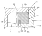
- 4 is an enlarged cross-sectional view of a portion of the buffer stopper according to the embodiment.
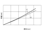
- FIG. FIG. 4 is a characteristic diagram of the buffer stopper according to the embodiment.
- FIG. 11 is a cross-sectional view showing a modified example of a buffer stopper.
- FIG. 1 is a diagram showing a conventional shock absorbing stopper. 1 is an example of another conventional shock absorbing stopper for reducing costs.
- a rack-and-pinion type steering device is used in vehicles such as automobiles.
- the steering device includes, for example, a steering wheel operated by a driver, a steering shaft connected to the wheel, a pinion gear coaxial with the steering shaft, and a shaft provided with a rack gear that converts the rotation of the pinion gear into movement along the axial direction.
- the movement of the shaft is transmitted to the wheels via a tie rod.
- the tie rod oscillates relative to the shaft in response to the movement of the shaft, the wheels can be turned in any direction.
- the shaft is accommodated in a housing.
- Such steering devices are equipped with a damper device to reduce the impact between the shaft and the housing caused by the swinging of the tie rod.
- FIG. 1 is a cross-sectional view showing a part of a steering device 100 including a buffer stopper 1 according to an embodiment.
- a part of the steering device 100 is illustrated in FIG. 1.
- the steering device 100 has a shaft 3, a tie rod 4, a housing 5, a rack boot 6, and a damper device 10.
- the damper device 10 includes a flange portion 30, a protrusion 50, and a buffer stopper 1. Note that the flange portion 30 is connected to the shaft 3, and the protrusion 50 is connected to the housing 5, but it can also be considered that the flange portion 30 is part of the shaft 3, and the protrusion 50 is part of the housing 5.
- the shaft 3 is, for example, cylindrical.
- a rack gear 35 is provided on the shaft 3 along the axial direction. Note that the "axial direction" is the direction along the central axis A of the shaft 3, which coincides with the extension direction of the shaft 3.
- the rack gear 35 is configured to mesh with a pinion gear (not shown), and converts the rotational motion of the pinion gear into linear motion along the central axis A. Therefore, the shaft 3 is movable in the axial direction.
- the material of the shaft 3 is, for example, metal.
- the housing 5 is a cylindrical enclosure that houses the shaft 3.
- the housing 5 is fixed, for example, to a vehicle body (not shown).
- the housing 5 is, for example, cylindrical and extends along the axial direction.
- the inner diameter of the housing 5 is slightly larger than the diameter of the shaft 3.
- the material of the housing 5 is, for example, a metal.
- the flange portion 30 of the damper device 10 is a stud end attached to the end of the shaft 3.
- the material of the flange portion 30 is, for example, a metal.
- the flange portion 30 has a flange body 301 and a protrusion 302.
- the flange body 301 is, for example, cylindrical.
- the outer diameter of the flange body 301 is larger than the outer diameter of the shaft 3.
- An opening 301D is provided in the flange body 301.
- the opening 301D is a bottomed hole that opens on the side of the flange body 301 opposite the convex portion 302.
- the opening 301D accommodates the ball joint 40 of the tie rod 4.
- the ball joint 40 is accommodated in the opening 301D via the cushioning material 401.
- the tie rod 4 oscillates around the central axis A as the rack gear 35 moves along the central axis A.
- the flange main body 301 has a first annular surface 30s.
- the first annular surface 30s protrudes radially outward from the outer peripheral surface 3s of the shaft 3.
- "Radially outward” refers to a direction perpendicular to the central axis A of the shaft 3 and away from the central axis A.
- the direction perpendicular to the central axis A of the shaft 3 and heading from the housing 5 side toward the central axis A is referred to as "radially inward.”
- the direction perpendicular to the central axis A of the shaft 3 is referred to as the "radial direction.”
- the convex portion 302 is a portion that protrudes from the flange body 301 toward the shaft 3, and is formed integrally with the flange body 301.
- the convex portion 302 is, for example, cylindrical.
- a recess 3D is provided at the end of the shaft 3, and the convex portion 302 is disposed inside the recess 3D.
- a female thread is formed on one of the inner circumferential surface of the recess 3D and the outer circumferential surface of the convex portion 302, and a male thread is formed on the other.
- the convex portion 302 and the recess 3D are screwed together. This screwing connects the flange portion 30 to the shaft 3.
- the protrusion 50 of the damper device 10 is an annular structure that protrudes radially inward from the inner peripheral surface 5s of the housing 5, and is formed integrally with the housing 5.
- the protrusion 50 surrounds the outer peripheral surface 3s of the shaft 3.
- the protrusion 50 is, for example, annular.
- the inner diameter of the protrusion 50 is slightly larger than the outer diameter of the shaft 3.
- the protrusion 50 is spaced apart from the flange main body 301.
- the protrusion 50 has a second annular surface 50s.
- the second annular surface 50s is an end face of the protrusion 50 located on the flange portion 30 side.
- the second annular surface 50s protrudes radially inward from the inner peripheral surface of the housing 5.
- the second annular surface 50s faces the first annular surface 30s at a distance.
- the housing 5 is also provided with a storage section 50H.
- the storage section 50H is a space defined by the second annular surface 50s and a portion of the inner peripheral surface 5s of the housing 5 that is closer to the ball joint 40 than the protruding portion 50.
- the aforementioned flange main body 301 is contained in the storage section 50H.
- the inner diameter of the wall defining the storage section 50H is larger than the outer diameter of the flange main body 301.
- a rack boot 6 is also connected to the housing 5.
- the rack boot 6 is cylindrical and bellows-shaped.
- the tie rod 4 is contained inside the rack boot 6.
- the buffer stopper 1 of the damper device 10 is provided between the flange portion 30 and the protruding portion 50. Specifically, the buffer stopper 1 is provided between the first annular surface 30s of the flange portion 30 and the second annular surface 50s of the protruding portion 50. Such a buffer stopper 1 is provided to reduce the impact between the shaft 3 and the housing 5 caused by the swinging of the tie rod 4.
- cushioning Stopper Fig. 2 is a cross-sectional view showing a part of the cushioning stopper 1 according to the embodiment. As shown in Fig. 2, the cushioning stopper 1 includes a metal ring 11, a cushioning body 12, and an annular member 13.
- the metal ring 11 is an annular flat plate, and in this embodiment, it is a circular flat plate.
- the metal ring 11 is made of metal.
- the metal ring 11 is made of a hot-rolled mild steel plate such as SPHC.
- the buffer 12 is joined to the metal ring 11 by, for example, vulcanization adhesion.
- the buffer 12 is tubular, and in this embodiment, is substantially cylindrical.
- the length of the buffer 12 along the axial direction is longer than the length of the metal ring 11 along the axial direction.
- the buffer 12 has elasticity that absorbs shock.
- the rigidity of the buffer 12 is lower than the rigidity of the metal ring 11.
- the material of the buffer 12 is a rubber-like elastic material.
- the rubber-like elastic material means a thermosetting elastomer, a synthetic resin having rubber-like elasticity, and a mixed material containing rubber.
- a specific material for the buffer 12 is preferably, for example, nitrile rubber (NBR) from the viewpoint of high hardness and improved durability.
- NBR nitrile rubber
- a material in which carbon black is added to nitrile rubber (NBR) is more preferably, for example, the material for the buffer 12.
- the difference between the inner and outer diameters of the buffer 12 is slightly shorter than the difference between the inner and outer diameters of the metal ring 11, but may be the same.
- the difference between the inner and outer diameters is the length in the radial direction.
- the occupancy ratio of the buffer 12 in the buffer stopper 1 is greater than the occupancy ratio of the metal ring 11 in the buffer stopper 1.
- the buffer 12 also has a covering portion 121.
- the covering portion 121 is a portion of the buffer 12 that covers the outer peripheral surface 111 of the metal ring 11.
- the inner peripheral surface 112 of the metal ring 11 is not covered by the buffer 12.
- the annular member 13 is joined to the buffer 12, for example, by vulcanization adhesion.
- the annular member 13 is annular, and in this embodiment, is circular.
- the annular member 13 is provided on the side of the buffer 12 opposite the metal ring 11.
- the annular member 13 is spaced apart from the metal ring 11.
- the buffer 12 has a portion located between the annular member 13 and the metal ring 11.
- the annular member 13 is provided on the radially inner side of the buffer 12.
- the occupancy ratio of the annular member 13 in the buffer stopper 1 is smaller than the occupancy ratio of the buffer 12 in the buffer stopper 1.
- the occupancy ratio of the annular member 13 in the buffer stopper 1 is also smaller than the occupancy ratio of the metal ring 11 in the buffer stopper 1.
- the difference between the inner and outer diameters of the buffer 12 is also shorter than the length of the difference between the inner and outer diameters of the buffer 12. In this embodiment, the difference between the inner and outer diameters of the annular member 13 increases the farther it is from the metal ring 11.
- the rigidity of the annular member 13 is higher than the rigidity of the buffer 12.
- the Young's modulus of the annular member 13 is higher than the Young's modulus of the buffer 12.
- the material of the annular member 13 is, for example, a metal, a resin, or a rubber-like elastic material.
- the Young's modulus of the annular member 13 is not particularly limited, but is, for example, 100 MPa to 1000 MPa.
- the Young's modulus of the buffer 12 is not particularly limited, but is, for example, 1 kgf/ cm2 to 100 kgf/ cm2 .
- the Young's modulus of the metal ring 11 is not particularly limited, but is, for example, 10 GPa to 500 GPa.
- FIG. 3 is an enlarged cross-sectional view of a portion of the buffer stopper 1 according to the embodiment.
- the buffer stopper 1 is provided between the first annular surface 30s and the second annular surface 50s and is in contact with them.
- the buffer stopper 1 is press-fitted between the first annular surface 30s and the second annular surface 50s so that the buffer 12 is elastically deformable.
- the buffer stopper 1 is not in contact with the shaft 3 and the housing 5, but may be in contact with the shaft 3, for example.
- the metal ring 11 of the buffer stopper 1 contacts the first annular surface 30s. Additionally, the buffer 12 and the annular member 13 each contact the second annular surface 50s. Specifically, the end face 125 of the buffer 12 opposite the metal ring 11 and the end face 135 of the annular member 13 opposite the metal ring 11 contact the second annular surface 50s. Additionally, as shown in FIG. 2, in an unattached state in which the buffer stopper 1 is not provided between the first annular surface 30s and the second annular surface 50s, the end faces 125 and 135 are continuous and flush with no steps.
- the shock absorber 1 receives the shock caused by the swinging of the tie rod 4 at the metal ring 11, and the shock absorber 12 is compressed and elastically deformed by the shock received by the metal ring 11.
- the shock absorber 12 is compressed in the axial direction and expands radially inward and outward by the amount of compression.
- the shock absorber 1 is pressed against the first annular surface 30s and the second annular surface 50s. In this way, the shock absorber 1 mainly absorbs the shock with the shock absorber 12.
- the buffer stopper 1 having the above configuration has a metal ring 11, a buffer 12, and an annular member 13.
- the metal ring 11 contacts the first annular surface 30s.
- the metal ring 11 is an annular flat plate.
- the buffer 12 includes a rubber-like elastic material, is provided between the first annular surface 30s and the second annular surface 50s, and is joined to the metal ring 11.
- the annular member 13 includes a rubber-like elastic material, is provided between the first annular surface 30s and the second annular surface 50s, and is joined to the buffer 12.
- the buffer stopper 1 has a metal ring 11, which allows it to absorb or cushion loads that cannot be absorbed by the buffer 12 alone.
- the metal ring 11 is an annular flat plate, which allows the metal ring 11 to be constructed as a single member, and makes it easier to lower the proportion of the metal ring 11 in the buffer stopper 1 compared to conventional methods. This allows for lower costs than conventional methods.
- the rigidity of the annular member 13 is higher than that of the buffer 12. Therefore, the surface pressure of the annular member 13 against the second annular surface 50s can be made higher than the surface pressure of the buffer 12 against the second annular surface 50s.
- the annular member 13 is provided on the radially inner side of the buffer 12. Therefore, the annular member 13 can function as a sealing member that stops the intrusion of lubricating grease between the buffer 12 and the second annular surface 50s. Therefore, by providing such an annular member 13, it is possible to suppress the risk that the lubricating grease applied to the shaft 3 will leak outward in the radial direction and intrude between the buffer 12 and the second annular surface 50s. Therefore, the durability of the buffer 12 can be improved.
- the lubricating grease would get into the gap between the buffer 12 and the second annular surface 50s. In this case, the coefficient of friction between the end face 125 of the buffer 12 and the second annular surface 50s would decrease. This would make the buffer 12 more susceptible to deformation, resulting in a larger amount of deflection than intended. As a result, the durability of the buffer stopper 1 could be compromised.
- an annular member 13 is provided. This makes it possible to prevent the intrusion of lubricating grease between the buffer 12 and the second annular surface 50s. This makes it difficult for the coefficient of friction to decrease as described above to occur. This prevents the buffer 12 from deforming and causing the amount of deflection to become greater than intended. As a result, the durability of the buffer stopper 1 can be improved.
- the annular member 13 is spaced apart from the metal ring 11. Therefore, even if the gap between the first annular surface 30s and the second annular surface 50s is reduced and the buffer 12 is compressed in the axial direction, the annular member 13 can be prevented from being pinched between the second annular surface 50s and the metal ring 11 and being damaged. If the metal ring 11 and the annular member 13 were connected, and the buffer 12 was compressed in the axial direction, the annular member 13 would be crushed by the metal ring 11 and the second annular surface 50s and be damaged. Furthermore, because the annular member 13 is spaced apart from the metal ring 11, when the buffer 12 is compressed in the axial direction, the buffer 12 is easily elastically deformed in the radial direction.
- the annular member 13 is provided on the radially inner side of the buffer 12. Therefore, the buffer 12 is in contact with the second annular surface 50s. Therefore, the buffer performance of the buffer 12 can be more suitably exhibited than when the end surface 125 of the buffer 12 is covered with the annular member 13 and the buffer 12 is not in contact with the second annular surface 50s.
- FIG. 4 is a characteristic diagram of the buffer stopper 1 according to the embodiment.
- the horizontal axis of FIG. 4 is the amount of displacement [mm] of the buffer stopper 1, and the vertical axis is the load [kN] applied to the buffer stopper 1.
- the amount of displacement of the buffer stopper 1 can also be considered to correspond to the compressive strain along the axial direction of the buffer 12.
- the characteristic line L1 shown by a solid line indicates the buffer stopper 1 of this embodiment.
- the characteristic line L2 shown by a dashed line indicates the buffer stopper 7 of the comparative example in FIG. 7.
- the buffer stopper 1 of this embodiment has an annular member 13, whereas the buffer stopper 7 of the comparative example does not have an annular member 13.
- the volume of the buffer stopper 1 of this embodiment and the volume of the buffer stopper 7 of the comparative example are the same.
- the slope of characteristic line L1 is greater than the slope of characteristic line L2 of the comparative example. Therefore, the linear region of characteristic line L1, i.e., the region below characteristic line L1, is greater than the linear region of characteristic line L2 of the comparative example, i.e., the region below characteristic line L2. Therefore, with the buffer stopper 1 of this embodiment, the amount of absorbed energy, i.e., the maximum amount of compressive displacement, can be significantly increased compared to the comparative example. Accordingly, the amount of deflection upon impact can be reduced. Therefore, with the buffer stopper 1 of this embodiment, the buffer performance and durability of the buffer stopper 1 can be improved compared to the comparative example. In particular, the buffer performance and durability can be improved without increasing the volume of the buffer stopper 1 compared to the comparative example.
- the coefficient of friction of the end surface 125 of the buffer 12 decreases, and as a result, the internal stress of the buffer 12 is thought to increase. This reduces the amount of energy that the buffer 12 can absorb, and the buffer performance is thought to decrease.
- the buffer stopper 1 of this embodiment can reduce the risk of such a decrease in buffer performance.
- the material of the annular member 13 is, for example, metal or resin, but it is preferable that the annular member 13 contains resin. By making the annular member 13 contain resin, the annular member 13 can be easily formed into any shape.
- the material of the annular member 13 is not particularly limited, but is preferably a super engineering plastic such as polytetrafluoroethylene (PTFE) or polyether ether ketone (PEEK). Such materials are preferable because they are particularly durable and impact resistant. By using such materials, the intrusion of lubricating grease between the buffer 12 and the second annular surface 50s can be more effectively prevented than when other materials are used.
- PTFE polytetrafluoroethylene
- PEEK polyether ether ketone
- the material of the annular member 13 has excellent resistance to lubricating grease.
- super engineering plastics such as PTFE and PEEK can exhibit resistance to various types of lubricating grease.
- the volume of the annular member 13 is smaller than the volume of the buffer 12. If the volume of the annular member 13 is larger than the volume of the buffer 12, the buffer performance of the buffer stopper 1 will be reduced compared to when the volume of the annular member 13 is smaller. Therefore, by making the volume of the annular member 13 smaller than the volume of the buffer 12, it is possible to suppress the reduction in the buffer performance of the buffer stopper 1 caused by the reduction in the occupancy rate of the buffer by providing the annular member 13.
- the joint surface 130 of the annular member 13 with the buffer body 12 is inclined with respect to the axial direction.
- the difference between the inner and outer diameters of the annular member 13 increases in the direction away from the metal ring 11. Therefore, the cross-sectional shape of the annular member 13 is triangular.
- FIG. 5 is a cross-sectional view showing a modified buffer stopper 1A.
- the difference between the inner and outer diameters of the annular member 13A of the buffer stopper 1A in FIG. 5 is constant in the axial direction. Therefore, the cross-sectional shape of the annular member 13A is rectangular. This annular member 13A can also achieve the same effect as the previously described annular member 13.
- the surface pressure on the second annular surface 50s can be increased compared to the annular member 13A of FIG. 5.
- the force on the buffer 12 is applied to the joint surface 130 as the first annular surface 30s and the second annular surface 50s approach each other.
- the force on the second annular surface 50s of the tip portion 139 of the annular member 13 can be increased. Therefore, the sealing performance of the annular member 13 can be particularly improved. Therefore, the risk of the lubricating grease entering between the buffer 12 and the second annular surface 50s can be particularly effectively suppressed. This makes it possible to particularly improve the durability and buffer performance of the buffer stopper 1.
- the cross-sectional shape of the annular member 13 is not limited to the examples shown in Figures 3 and 5.
- the joining surface 130 may be curved.
- the buffer 12 has a covering portion 121.
- the covering portion 121 is a portion that covers the outer peripheral surface 111 of the metal ring 11.
- the damper device 10 including the buffer stoppers 1 and 1A described above may be applied to vehicles, as well as transportation equipment and industrial equipment.
- the buffer stopper of the first embodiment which is a preferred example of the present disclosure, is disposed between a flange portion having a first annular surface extending from the outer peripheral surface of an axially movable shaft, and a protruding portion having a second annular surface extending from the inner peripheral surface of a cylindrical housing that accommodates the shaft toward the shaft, the second annular surface being spaced apart from and facing the first annular surface, and includes a metal ring that contacts the first annular surface, an annular buffer body provided between the metal ring and the second annular surface and joined to the metal ring, and an annular member provided between the buffer body and the second annular surface and joined to the buffer body, the buffer body including a rubber-like elastic material, the metal ring being an annular flat plate, the annular member being spaced apart from the metal ring and disposed radially inward of the buffer body, and the rigidity of the annular member being higher than the rigidity of the buffer body.
- the metal ring is an annular flat plate, it is easy to form the metal ring from a single member, and costs can be reduced compared to conventional methods. Furthermore, since the annular member is provided on the radial inside of the buffer body and has a higher rigidity than the buffer body, the risk of lubricating grease entering between the buffer body and the second annular surface can be reduced. This improves the durability of the buffer body. Furthermore, since the annular member is spaced apart from the metal ring, the risk of the annular member being damaged even if the buffer body is compressed can be avoided. Thus, according to the first aspect, it is possible to improve the buffer performance and durability while reducing costs.
- the annular member contains resin. This allows the annular member to be easily formed into any shape, providing a shock-absorbing stopper with excellent durability.
- the volume of the annular member is smaller than the volume of the buffer body. Therefore, by providing the annular member, the occupancy rate of the buffer body is reduced, which can suppress the deterioration of the buffer performance of the buffer stopper.
- the buffer further has a portion that covers the outer peripheral surface of the metal ring. The provision of this portion prevents the metal ring from coming into contact with the housing. This makes it possible to prevent abnormal noise from occurring.
- the end face of the buffer opposite the metal ring and the end face of the annular member opposite the metal ring are flush with each other. This makes it easier to equalize the surface pressure of the annular member against the second annular surface. This effectively prevents lubricating grease from entering between the buffer and the second annular surface.
- the joint surface of the annular member with the buffer is inclined with respect to the axial direction, and the difference between the inner and outer diameters of the annular member increases in the direction away from the metal ring.
- the force applied to the second annular surface at the tip of the annular member can be increased. This makes it possible to particularly effectively suppress the risk of lubricating grease penetrating between the buffer and the second annular surface.
- Buffer stopper 1A... Buffer stopper, 2... Buffer stopper, 3... Shaft, 3s... Outer circumferential surface, 4... Tie rod, 5... Housing, 5s... Inner circumferential surface, 6... Rack boot, 7... Buffer stopper, 9... Buffer stopper, 10... Damper device, 11... Metal ring, 12... Buffer body, 13... Annular member, 13A... Annular member, 30... Flange portion, 30s... First annular surface, 35... Rack gear, 40... Ball joint, 50... Protrusion, 50H...
- Storage portion 50 s...second annular surface, 71...metal ring, 72...rubber-like elastic body, 81...rack bar, 82...rack housing, 83...tie rod, 91...L-shaped metal ring, 93...rubber-like elastic body, 100...steering device, 111...outer peripheral surface, 112...inner peripheral surface, 121...covering portion, 125...end surface, 130...joint surface, 135...end surface, 139...tip portion, 301...flange body, 301D...opening, 302...projection, 401...cushion material, A...center axis, L1...characteristic line, L2...characteristic line.
Landscapes
- Engineering & Computer Science (AREA)
- Mechanical Engineering (AREA)
- General Engineering & Computer Science (AREA)
- Chemical & Material Sciences (AREA)
- Combustion & Propulsion (AREA)
- Transportation (AREA)
- Vibration Dampers (AREA)
Abstract
緩衝ストッパーは、軸方向に移動可能なシャフトの外周面から張り出す第1環状面を有するフランジ部と、シャフトを収容する筒状のハウジングの内周面からシャフト側へ張り出す第2環状面であって、第1環状面と離間する第2環状面を有する突出部との間に配置される緩衝ストッパーであって、第1環状面に接触する金属環と、金属環と第2環状面との間に設けられ、金属環に接合された環状の緩衝体と、緩衝体と第2環状面との間に設けられ、緩衝体に接合された環状部材と、を備え、緩衝体は、ゴム状弾性材料を含み、金属環は、環状平板であり、環状部材は、金属環と離間し、かつ緩衝体の径方向の内側に設けられ、環状部材の剛性は、緩衝体の剛性よりも高い。
Description
本開示は、緩衝ストッパーに関する。
例えば自動車等には、ステアリング装置が用いられている。ステアリング装置は、運転者が操作するステアリングホイールと、当該ホイールに連結されたステアリングシャフトと、当該ステアリングシャフトと同軸のピニオンギアと、当該ギアの回転を軸方向に沿った移動に変換するラックギアを有するラックバーと、を備える。ラックバーの移動は、タイロッドを介して車輪へと伝達される。ラックバーの移動に伴いタイロッドが揺動することで、車輪を任意の方向へ旋回させることができる。また、ラックバーは、ラックハウジング内に収容されている。
当該ステアリング装置では、タイロッドの揺動によるラックバーとラックハウジングとの間の衝撃を緩和するための緩衝ストッパーが設けられている。例えば、特許文献1に記載の緩衝ストッパーが挙げられる。
図6は、従来の緩衝ストッパー9を示す図である。図6には、ラックバー81、ラックハウジング82、およびタイロッド83が図示される。図6の緩衝ストッパー9は、ラックバー81に接触するL字金属環91と、L字金属環91とラックハウジング82との間に設けられたゴム状弾性体93とを有する。L字金属環91が設けられることで高荷重入力に対する耐久性を高めることができる。
しかし、L字金属環91は、ラックバー81の中心軸Aに沿った方向に延在する部分と径方向に沿った方向に延在する部分との二部材で構成されており、かつ緩衝ストッパー9における占有比率が高い。このため、高コストである。
図7は、低コスト化を図るための他の従来の緩衝ストッパー7の例示である。図7の緩衝ストッパー7は、円環平板状の金属環71と、金属環71とラックハウジング82との間に設けられたゴム状弾性体72とを有する。金属環71を円環平板状にすることで、低コスト化を図ることができる。
緩衝ストッパー7の構成では、ラックバー81のラックハウジング82に対する衝撃緩衝を機能は、主としてゴム状弾性体72が担っている。この構成では、ラックバー81に塗布された潤滑グリースがラックハウジング82とゴム状弾性体72との間に付着した場合、ラックハウジング82とゴム状弾性体72との各接触面の摩擦係数が低下してしまう。このため、ゴム状弾性体72が変形し易くなり、たわみ量が意図した量よりも大きくなってしまう。この結果、緩衝ストッパー7の耐久性が悪化するおそれがある。
このようなことから、従来よりも低コスト化を図りつつ、耐久性の向上を図ることができる緩衝ストッパーが求められている。
以上の課題を解決するために、本開示の一態様に係る緩衝ストッパーは、軸方向に移動可能なシャフトの外周面から張り出す第1環状面を有するフランジ部と、前記シャフトを収容する筒状のハウジングの内周面から前記シャフト側へ張り出す第2環状面であって、前記第1環状面と離間して対向する前記第2環状面を有する突出部との間に配置される緩衝ストッパーであって、前記第1環状面に接触する金属環と、前記金属環と前記第2環状面との間に設けられ、前記金属環に接合された環状の緩衝体と、前記緩衝体と前記第2環状面との間に設けられ、前記緩衝体に接合された環状部材と、を備え、前記緩衝体は、ゴム状弾性材料を含み、前記金属環は、環状平板であり、前記環状部材は、前記金属環と離間し、かつ前記緩衝体の径方向の内側に設けられ、前記環状部材の剛性は、前記緩衝体の剛性よりも高い。
本開示によれば、従来よりも低コスト化を図りつつ、緩衝性能の向上、および耐久性の向上を図ることができる。
以下、添付図面を参照しながら本開示に係る好適な実施形態を説明する。なお、図面において各部の寸法または縮尺は実際と適宜に異なり、理解を容易にするために模式的に示す部分もある。また、本開示の範囲は、以下の説明において特に本開示を限定する旨の記載がない限り、これらの形態に限られない。
1.ステアリング装置
自動車等の車両には、例えば、ラックアンドピニオン方式のステアリング装置が用いられている。当該ステアリング装置は、例えば、運転者が操作するステアリングホイールと、当該ホイールに連結されたステアリングシャフトと、当該ステアリングシャフトと同軸のピニオンギアと、当該ピニオンギアの回転を軸方向に沿った移動に変換するラックギアが設けられたシャフトとを備える。シャフトの移動は、タイロッドを介して車輪へと伝達される。シャフトの移動に伴いタイロッドがシャフトに対して揺動することで、車輪を任意の方向へ旋回させることができる。また、シャフトは、ハウジング内に収容されている。
自動車等の車両には、例えば、ラックアンドピニオン方式のステアリング装置が用いられている。当該ステアリング装置は、例えば、運転者が操作するステアリングホイールと、当該ホイールに連結されたステアリングシャフトと、当該ステアリングシャフトと同軸のピニオンギアと、当該ピニオンギアの回転を軸方向に沿った移動に変換するラックギアが設けられたシャフトとを備える。シャフトの移動は、タイロッドを介して車輪へと伝達される。シャフトの移動に伴いタイロッドがシャフトに対して揺動することで、車輪を任意の方向へ旋回させることができる。また、シャフトは、ハウジング内に収容されている。
かかるステアリング装置には、タイロッドの揺動によるシャフトとハウジングとの間の衝撃を緩和するためのダンパー装置が設けられている。
図1は、実施形態における緩衝ストッパー1を備えるステアリング装置100の一部を示す断面図である。図1には、ステアリング装置100の一部が図示される。具体的には、ステアリング装置100は、シャフト3とタイロッド4とハウジング5とラックブーツ6とダンパー装置10とを有する。ダンパー装置10は、フランジ部30と突出部50と緩衝ストッパー1とを含む。なお、フランジ部30はシャフト3に接続され、突出部50はハウジング5に接続されるが、フランジ部30はシャフト3の一部であり、突出部50はハウジング5の一部であるとも捉えられる。
シャフト3は、例えば円柱状である。シャフト3には、軸方向に沿ってラックギア35が設けられる。なお、「軸方向」は、シャフト3の中心軸Aに沿った方向であり、シャフト3の延在方向と一致する。ラックギア35は、図示省略されたピニオンギアに噛み合うよう構成されており、ピニオンギアの回転運動を中心軸Aに沿った直線運動に変換する。よって。シャフト3は、軸方向に移動可能である。シャフト3の材料は、例えば金属である。
ハウジング5は、シャフト3を収容する筒状の筐体である。ハウジング5は、例えば、図示省略された車体に固定される。ハウジング5は、例えば円筒状であり、軸方向に沿って延在する。ハウジング5の内径は、シャフト3の径よりも若干大きい。ハウジング5の材料は、例えば金属である。
ダンパー装置10が有するフランジ部30は、シャフト3の端部に装着されたスタッドエンドである。フランジ部30の材料は、例えば金属である。フランジ部30は、フランジ本体301と凸部302とを有する。
フランジ本体301は、例えば円柱状である。フランジ本体301の外径は、シャフト3の外径よりも大きい。フランジ本体301には、開口部301Dが設けられる。開口部301Dは、フランジ本体301のうち凸部302とは反対側に開口する有底孔である。開口部301Dには、タイロッド4が有するボールジョイント40が収容される。ボールジョイント40は、緩衝材401を介して開口部301Dに収容される。また、タイロッド4は、ラックギア35の中心軸Aに沿った移動に伴い、中心軸Aを中心として揺動する。
また、フランジ本体301は、第1環状面30sを有する。第1環状面30sは、シャフト3の外周面3sから径方向外側へ張り出している。「径方向外側」とは、シャフト3の中心軸Aに直交し、中心軸Aから離れる方向である。また、以下では、シャフト3の中心軸Aに直交し、ハウジング5側から中心軸Aへ向かう方向を「径方向内側」とする。さらに、シャフト3の中心軸Aに直交する方向を「径方向」とする。
凸部302は、フランジ本体301からシャフト3に向かって突出する部分であり、フランジ本体301と一体で形成される。凸部302は、例えば、円柱状である。シャフト3の端部には、凹部3Dが設けられており、当該凹部3Dの内部に凸部302が配置される。例えば、凹部3Dの内周面および凸部302の外周面のうちの一方に、雌ねじが形成され、他方に雄ねじが形成されている。凸部302および凹部3Dとは、螺合している。この螺合によって、フランジ部30がシャフト3に連結されている。
ダンパー装置10が有する突出部50は、ハウジング5の内周面5sから径方向内側へ突出する環状の構造体であり、ハウジング5と一体的に形成される。突出部50は、シャフト3の外周面3sを包囲する。突出部50は、例えば円環状である。突出部50の内径は、シャフト3の外径よりも若干大きい。突出部50は、フランジ本体301に対して離間する。
突出部50は、第2環状面50sを有する。第2環状面50sは、突出部50のうちフランジ部30側に位置する端面である。第2環状面50sは、ハウジング5の内周面から径方向内側へ張り出している。第2環状面50sは、第1環状面30sに対して離間し対向する。
また、ハウジング5には、収容部50Hが設けられる。収容部50Hは、第2環状面50sと、ハウジング5の内周面5sのうちの突出部50よりもボールジョイント40側の部分とにより画定される空間である。収容部50Hには、前述のフランジ本体301が収容される。収容部50Hを画定する壁面の内径は、フランジ本体301の外径よりも大きい。また、ハウジング5には、ラックブーツ6が接続されている。ラックブーツ6は、円筒蛇腹状である。ラックブーツ6の内部には、タイロッド4が収容されている。
ダンパー装置10が有する緩衝ストッパー1は、フランジ部30と突出部50との間に設けられる。具体的には、緩衝ストッパー1は、フランジ部30の第1環状面30sと突出部50の第2環状面50sとの間に設けられている。かかる緩衝ストッパー1は、タイロッド4の揺動によるシャフト3とハウジング5との間の衝撃を緩和するために設けられている。
2.緩衝ストッパー
図2は、実施形態に係る緩衝ストッパー1の一部を示す断面図である。図2に示すように、緩衝ストッパー1は、金属環11と緩衝体12と環状部材13とを備える。
図2は、実施形態に係る緩衝ストッパー1の一部を示す断面図である。図2に示すように、緩衝ストッパー1は、金属環11と緩衝体12と環状部材13とを備える。
金属環11は、環状平板であり、本実施形態では円環平板状である。金属環11は、金属製である。具体的には例えば、金属環11は、SPHC等の熱間圧延軟鋼板等で構成される。
緩衝体12は、例えば加硫接着により金属環11に接合される。緩衝体12は、筒状であり、本実施形態ではほぼ円筒状である。緩衝体12は、緩衝体12の軸方向に沿った長さは、金属環11の軸方向に沿った長さよりも長い。緩衝体12は、衝撃を吸収する弾性を有する。緩衝体12の剛性は、金属環11の剛性よりも低い。緩衝体12の材料は、ゴム状弾性材料である。ゴム状弾性材料とは、熱硬化性エラストマーであるゴム、およびゴム状弾性を有する合成樹脂、およびゴムを含む混合材料を含む意味である。具体的な緩衝体12の材料としては、高硬度および耐久性向上の観点から、例えばニトリルゴム(NBR)であることが好ましい。さらに、緩衝体12の材料としては、例えばニトリルゴム(NBR)にカーボンブラックが添加された材料であることがより好ましい。
なお、緩衝体12の内外径差は、金属環11の内外径差よりも若干短いが、同じでもよい。当該内外径差とは、径方向の長さである。また、緩衝ストッパー1における緩衝体12の占有比率は、金属環11の緩衝ストッパー1における占有比率よりも大きい。
また、緩衝体12は、被覆部121を有する。被覆部121は、緩衝体12のうち金属環11の外周面111を覆う部分である。なお、金属環11の内周面112は、緩衝体12によって覆われていない。
環状部材13は、例えば加硫接着により緩衝体12に接合される。環状部材13は、環状であり、本実施形態では円環状である。環状部材13は、緩衝体12のうち金属環11とは反対の面側に設けられる。環状部材13は、金属環11と離間している。別の見方をすると、緩衝体12は、環状部材13と金属環11との間に位置する部分を有する。また、環状部材13は、緩衝体12のうち径方向での内側に設けられる。
環状部材13の緩衝ストッパー1における占有比率は、緩衝体12の緩衝ストッパー1における占有比率よりも小さい。また、環状部材13の緩衝ストッパー1における占有比率は、金属環11の緩衝ストッパー1における占有比率よりも小さい。また、緩衝体12の内外径差は、緩衝体12の内外径差の長さよりも短い。また、本実施形態では、環状部材13の内外径差は、金属環11から離れるほど大きくなる。
環状部材13の剛性は、緩衝体12の剛性よりも高い。例えば、環状部材13のヤング率は、緩衝体12のヤング率よりも高い。環状部材13の材料は、例えば、金属、樹脂またはゴム状弾性材料である。
環状部材13のヤング率は、特に限定されないが、例えば、100[MPa]以上1000[MPa]以下である。緩衝体12のヤング率は、特に限定されないが、例えば、1[kgf/cm2]以上100[kgf/cm2]以下である。金属環11のヤング率は、特に限定されないが、例えば、10[GPa]以上500[GPa]以下である。
図3は、実施形態にかかる緩衝ストッパー1の一部の断面を拡大した図である。図3に示すように、緩衝ストッパー1は、第1環状面30sと第2環状面50sとの間に設けられ、これらに接触している。例えば、緩衝ストッパー1は、緩衝体12が弾性変形可能なように第1環状面30sと第2環状面50sとの間に圧入されている。また、図示の例では、緩衝ストッパー1は、シャフト3およびハウジング5には接触していないが、例えば、シャフト3に接触していてもよい。
緩衝ストッパー1の金属環11は、第1環状面30sに接触する。また、緩衝体12および環状部材13のそれぞれは、第2環状面50sに接触する。具体的には、緩衝体12の金属環11とは反対の端面125と、環状部材13の金属環11とは反対の端面135とは、第2環状面50sに接触する。また、図2に示すように、緩衝ストッパー1が第1環状面30sと第2環状面50sとの間に設けられていない非装着状態で、端面125と端面135とは、段差無く連続しており、面一である。
かかる緩衝ストッパー1は、タイロッド4の揺動によって生じる衝撃を金属環11で受け、金属環11で受けた衝撃によって緩衝体12が圧縮され、弾性変形する。突出部50に対してフランジ部30と接近し、第1環状面30sと第2環状面50sとの間隔が縮小した場合、緩衝体12は、軸方向に圧縮され、圧縮された分、径方向内側および径方向外側に膨張する。この結果、緩衝ストッパー1は、第1環状面30sと第2環状面50sとの間で圧接された状態になる。このように、緩衝ストッパー1は、緩衝体12で主に当該衝撃を吸収する。
以上の構成の緩衝ストッパー1は、金属環11と緩衝体12と環状部材13とを有する。金属環11は、第1環状面30sに接触する。金属環11は、環状平板である。緩衝体12は、ゴム状弾性材料を含み、第1環状面30sと第2環状面50sとの間に設けられ、金属環11に接合される。環状部材13は、ゴム状弾性材料を含み、第1環状面30sと第2環状面50sとの間に設けられ、緩衝体12に接合される。
緩衝ストッパー1が金属環11を有することで、緩衝体12のみでは吸収しきれない荷重を吸収または緩衝することができる。また、金属環11が環状平板であることで、金属環11を一部材で構成することができ、かつ緩衝ストッパー1における金属環11の占有比率を従来よりも低くし易い。このため、従来よりも低コスト化を図ることができる。
さらに、環状部材13の剛性は、緩衝体12の剛性よりも高い。このため、環状部材13の第2環状面50sに対する面圧を緩衝体12の第2環状面50sに対する面圧よりも高くすることができる。そして、環状部材13は、緩衝体12に径方向の内側に設けられる。このため、緩衝体12と第2環状面50sとの間へ潤滑グリースの侵入を止める封止部材として環状部材13を機能させることができる。よって、かかる環状部材13が設けられることで、シャフト3に塗布された潤滑グリースが径方向外側に漏れ出して緩衝体12と第2環状面50sとの間に侵入するおそれを抑制することができる。それゆえ、緩衝体12の耐久性を向上させることができる。
仮に、環状部材13が設けられていない場合、潤滑グリースは緩衝体12と第2環状面50sとの間に侵入してしまう。この場合、緩衝体12の端面125と第2環状面50sとの各摩擦係数が低下してしまう。このため、緩衝体12が変形し易くなり、たわみ量が意図した量よりも大きくなってしまう。この結果、緩衝ストッパー1の耐久性が悪化するおそれがある。
これに対し、本実施形態では、環状部材13が設けられている。このため、緩衝体12と第2環状面50sとの間への潤滑グリースの侵入を抑制することができる。それゆえ、上記のような摩擦係数の低下が生じ難い。よって、緩衝体12が変形してたわみ量が意図した量よりも大きくなることが抑制される。この結果、緩衝ストッパー1の耐久性の向上を図ることができる。
また、前述のように、環状部材13は金属環11に対して離間している。このため、第1環状面30sと第2環状面50sとの間隔が縮小して緩衝体12が軸方向に圧縮しても、環状部材13が第2環状面50sおよび金属環11に挟まれた破損するおそれを回避することができる。仮に、金属環11と環状部材13とが接続されている場合、緩衝体12が軸方向に圧縮すると、環状部材13が金属環11と第2環状面50sとに圧し潰されて破損するおそれがある。また、環状部材13が金属環11に対して離間していることで、緩衝体12が軸方向に圧縮した場合、緩衝体12を径方向に弾性変形させ易い。
また、前述のように、環状部材13は、緩衝体12の径方向の内側に設けられている。このため、緩衝体12は第2環状面50sに接触している。それゆえ、緩衝体12の端面125が環状部材13で覆われていて緩衝体12が第2環状面50sに接触していない場合に比べ、緩衝体12による緩衝性能を好適に発揮することができる。
図4は、実施形態に係る緩衝ストッパー1の特性線図である。図4の横軸は、緩衝ストッパー1の変位量[mm]であり、縦軸は、緩衝ストッパー1にかかる荷重[kN]である。緩衝ストッパー1の変位量は、緩衝体12の軸方向に沿った圧縮歪みに相当するとも捉えられる。
また、実線で示す特性線L1は、本実施形態の緩衝ストッパー1を示す。破線で示す特性線L2は、図7の比較例の緩衝ストッパー7を示す。本実施形態の緩衝ストッパー1は環状部材13を有することに対し、比較例の緩衝ストッパー7は、環状部材13を有さない。なお、本実施形態の緩衝ストッパー1の体積と比較例の緩衝ストッパー7との体積は同じである。
特性線L1の傾きは、比較例の特性線L2の傾きよりも大きい。このため、特性線L1の線形領域、すなわち特性線L1よりも下方の領域は、比較例の特性線L2の線形領域、すなわち特性線L2よりも下方の領域に比べて大きい。このため、本実施形態の緩衝ストッパー1によれば、比較例に比べて、吸収エネルギー量、すなわち最大圧縮変位量をよく大きくすることができる。それに伴い、衝撃時のたわみ量を低くすることができる。このため、本実施形態の緩衝ストッパー1によれば、比較例に比べて、緩衝ストッパー1による緩衝性能および耐久性の向上を図ることができる。特に、緩衝ストッパー1の体積を比較例に比べて大きくすることなく、緩衝性能および耐久性を高めることができる。
緩衝体12と第2環状面50sとの間に潤滑グリースが存在する場合、緩衝体12の端面125の摩擦係数が低下し、この結果、緩衝体12の内部応力が大きくなると考えられる。このため、緩衝体12の吸収可能なエネルギー量が低下し、緩衝性能が低下すると考えられる。本実施形態の緩衝ストッパー1によれば、このような緩衝性能の低下が生じるおそれを抑制することができる。
また、前述のように、環状部材13の材料は、例えば金属または樹脂であるが、環状部材13は、樹脂を含むことが好ましい。環状部材13が樹脂を含むことで、環状部材13を任意の形状に簡単に形成することができる。
環状部材13が樹脂である場合、環状部材13の材料としては、特に限定されないが、ポリテトラフルオロエチレン(PTFE)、ポリエーテルエーテルケトン(PEEK)等のスーパーエンジニアリングプラスチックであることが好ましい。かかる材料は、耐久性および耐衝撃性に特に優れるため好ましい。かかる材料を用いることで、他の材料を用いる場合に比べて、潤滑グリースの緩衝体12と第2環状面50sとの間への侵入を効果的に抑制することができる。
また、環状部材13の材料は、潤滑グリースに対する耐性に優れていることが好ましい。例えばPTFEおよびPEEK等のスーパーエンジニアリングプラスチックであれば、各種の潤滑グリースに対する耐性を発揮することができる。
また、環状部材13の体積は、緩衝体12の体積よりも小さいことが好ましい。環状部材13の体積が緩衝体12の体積よりも大きい場合、小さい場合に比べて、緩衝ストッパー1の緩衝性能が低下してしまう。このため、環状部材13の体積が緩衝体12の体積よりも小さいことで、環状部材13を設けて緩衝体の占有率が低減することによる緩衝ストッパー1の緩衝性能の低下を抑制することができる。
また、前述の図2に示すように、緩衝ストッパー1に負荷がかかっていない状態において、緩衝体12の金属環11とは反対の端面125と、環状部材13の金属環11とは反対の端面135とは、面一である。このため、端面125と端面135との間に段差がある場合に比べ、端面135の全域において第2環状面50sに対する面圧の均一化を図り易い。このため、環状部材13による前述の封止性能を高めることができる。よって、潤滑グリースが緩衝体12と第2環状面50sとの間に侵入するおそれを効果的に抑制することができる。
図2および図3に示すように、環状部材13の緩衝体12との接合面130は、軸方向に対して傾斜している。そして、環状部材13の内外径差は、金属環11から遠ざかる方向に向かって大きくなっている。このため、環状部材13の断面形状は、三角形である。
図5は、変形例の緩衝ストッパー1Aを示す断面図である。図5の緩衝ストッパー1Aが有する環状部材13Aの内外径差は、軸方向において一定である。このため、環状部材13Aの断面形状は、四角形である。かかる環状部材13Aによっても、前述の環状部材13と同一の効果を発揮することができる。
ただし、図3の環状部材13によれば、図5の環状部材13Aに比べて、第2環状面50sに対する面圧を高めることができる。図3の環状部材13によれば、第1環状面30sおよび第2環状面50sが互いに近づくことにより緩衝体12にかかる力が接合面130にかかる。この結果、環状部材13の先端部139の第2環状面50sにかかる力を高くすることができる。よって、環状部材13による封止性能を特に高めることができる。それゆえ、潤滑グリースが緩衝体12と第2環状面50sとの間に侵入するおそれを特に効果的に抑制することができる。このため、緩衝ストッパー1による耐久性および緩衝性能を特に高めることができる。
なお、環状部材13の断面形状は、図3および図5に示す例に限定されない。例えば、接合面130は、湾曲していてもよい。
また、前述のように、緩衝体12は、被覆部121を有する。被覆部121は、金属環11の外周面111を覆う部分である。被覆部121が設けられることで、タイロッド4が揺動して緩衝ストッパー1がハウジング5に接触しても、金属環11とハウジング5とが接触することが回避される。このため、例えば、金属製のハウジング5と金属環11とが接触することにより異音が発生することを回避することができる。
2.変形例
以上に例示した形態は多様に変形され得る。前述の形態で例示した緩衝ストッパー1および1Aを備えるダンパー装置10は、車両のほか、例えば、輸送機器、および産業機器に適用可能である。
以上に例示した形態は多様に変形され得る。前述の形態で例示した緩衝ストッパー1および1Aを備えるダンパー装置10は、車両のほか、例えば、輸送機器、および産業機器に適用可能である。
以上、好適な実施形態に基づいて本開示を説明したが、本開示は前述の実施形態に限定されない。また、本開示の各部の構成は、前述の実施形態の同様の機能を発揮する任意の構成に置換でき、また、任意の構成を付加できる。
3.付記
以上の実施形態または変形例から、例えば以下の態様が把握される。
以上の実施形態または変形例から、例えば以下の態様が把握される。
本開示の好適例である第1態様の緩衝ストッパーは、軸方向に移動可能なシャフトの外周面から張り出す第1環状面を有するフランジ部と、前記シャフトを収容する筒状のハウジングの内周面から前記シャフト側へ張り出す第2環状面であって、前記第1環状面と離間して対向する前記第2環状面を有する突出部との間に配置される緩衝ストッパーであって、前記第1環状面に接触する金属環と、前記金属環と前記第2環状面との間に設けられ、前記金属環に接合された環状の緩衝体と、前記緩衝体と前記第2環状面との間に設けられ、前記緩衝体に接合された環状部材と、を備え、前記緩衝体は、ゴム状弾性材料を含み、前記金属環は、環状平板であり、前記環状部材は、前記金属環と離間し、かつ前記緩衝体の径方向の内側に設けられ、前記環状部材の剛性は、前記緩衝体の剛性よりも高い。
以上の第1態様によれば、金属環が環状平板であることで、金属環を一部材で形成し易く、従来よりも低コスト化を図ることができる。また、環状部材が緩衝体の径方向の内側に設けられ、環状部材の剛性が緩衝体の剛性よりも高いことで、潤滑グリースが緩衝体と第2環状面との間に侵入するおそれを抑制することができる。それゆえ、緩衝体の耐久性を向上させることができる。さらに、環状部材が金属環と離間していることで、緩衝体が圧縮しても環状部材が破損するおそれを回避することができる。このようなことから、第1態様によれば、低コスト化を図りつつ、緩衝性能の向上、および耐久性の向上を図ることができる。
第1態様の好適例である第2態様において、前記環状部材は、樹脂を含む。このため、環状部材を任意の形状に簡単に形成することができ、耐久性に優れる緩衝ストッパーを提供することができる。
第1態様の好適例である第3態様において、前記環状部材の体積は、前記緩衝体の体積よりも小さい。このため、環状部材を設けることで緩衝体の占有率が低減することによる緩衝ストッパーの緩衝性能の低下を抑制することができる。
第1態様の好適例である第4態様において、前記緩衝体は、前記金属環の外周面を覆う部分をさらに有する。当該部分が設けられることで、金属環とハウジングとが接触することが回避される。このため、異音が発生することを回避することができる。
第1態様の好適例である第5態様において、前記緩衝体の前記金属環とは反対の端面と、前記環状部材の前記金属環とは反対の端面とは、面一である。これにより、第2環状面に対する環状部材の面圧の均一化を図り易い。このため、潤滑グリースが緩衝体と第2環状面との間に侵入するおそれを効果的に抑制することができる。
第1態様の好適例である第6態様において、前記環状部材の前記緩衝体との接合面は、前記軸方向に対して傾斜しており、前記環状部材の内外径差は、前記金属環から遠ざかる方向に向かって大きくなる。以上の第6態様では、環状部材の先端部の第2環状面にかかる力を高くすることができる。よって、潤滑グリースが緩衝体と第2環状面との間に侵入するおそれを特に効果的に抑制することができる。
1…緩衝ストッパー、1A…緩衝ストッパー、2…緩衝ストッパー、3…シャフト、3s…外周面、4…タイロッド、5…ハウジング、5s…内周面、6…ラックブーツ、7…緩衝ストッパー、9…緩衝ストッパー、10…ダンパー装置、11…金属環、12…緩衝体、13…環状部材、13A…環状部材、30…フランジ部、30s…第1環状面、35…ラックギア、40…ボールジョイント、50…突出部、50H…収容部、50s…第2環状面、71…金属環、72…ゴム状弾性体、81…ラックバー、82…ラックハウジング、83…タイロッド、91…L字金属環、93…ゴム状弾性体、100…ステアリング装置、111…外周面、112…内周面、121…被覆部、125…端面、130…接合面、135…端面、139…先端部、301…フランジ本体、301D…開口部、302…凸部、401…緩衝材、A…中心軸、L1…特性線、L2…特性線。
Claims (6)
- 軸方向に移動可能なシャフトの外周面から張り出す第1環状面を有するフランジ部と、前記シャフトを収容する筒状のハウジングの内周面から前記シャフト側へ張り出す第2環状面であって、前記第1環状面と離間して対向する前記第2環状面を有する突出部との間に配置される緩衝ストッパーであって、
前記第1環状面に接触する金属環と、
前記金属環と前記第2環状面との間に設けられ、前記金属環に接合された環状の緩衝体と、
前記緩衝体と前記第2環状面との間に設けられ、前記緩衝体に接合された環状部材と、を備え、
前記緩衝体は、ゴム状弾性材料を含み、
前記金属環は、環状平板であり、
前記環状部材は、前記金属環と離間し、かつ前記緩衝体の径方向の内側に設けられ、
前記環状部材の剛性は、前記緩衝体の剛性よりも高い、
ことを特徴とする緩衝ストッパー。 - 前記環状部材は、樹脂を含む、
請求項1に記載の緩衝ストッパー。 - 前記環状部材の体積は、前記緩衝体の体積よりも小さい、
請求項1に記載の緩衝ストッパー。 - 前記緩衝体は、前記金属環の外周面を覆う部分をさらに有する請求項1に記載の緩衝ストッパー。
- 前記緩衝体の前記金属環とは反対の端面と、前記環状部材の前記金属環とは反対の端面とは、面一である、
請求項1に記載の緩衝ストッパー。 - 前記環状部材の前記緩衝体との接合面は、前記軸方向に対して傾斜しており、
前記環状部材の内外径差は、前記金属環から遠ざかる方向に向かって大きくなる、
請求項1に記載の緩衝ストッパー。
Applications Claiming Priority (2)
| Application Number | Priority Date | Filing Date | Title |
|---|---|---|---|
| JP2023201632 | 2023-11-29 | ||
| JP2023-201632 | 2023-11-29 |
Publications (1)
| Publication Number | Publication Date |
|---|---|
| WO2025115296A1 true WO2025115296A1 (ja) | 2025-06-05 |
Family
ID=95897270
Family Applications (1)
| Application Number | Title | Priority Date | Filing Date |
|---|---|---|---|
| PCT/JP2024/028279 Pending WO2025115296A1 (ja) | 2023-11-29 | 2024-08-07 | 緩衝ストッパー |
Country Status (1)
| Country | Link |
|---|---|
| WO (1) | WO2025115296A1 (ja) |
Citations (4)
| Publication number | Priority date | Publication date | Assignee | Title |
|---|---|---|---|---|
| US20120111132A1 (en) * | 2009-05-04 | 2012-05-10 | Trw Automotive Gmbh | Rack-And-Pinion Steering |
| JP2018192955A (ja) * | 2017-05-18 | 2018-12-06 | 株式会社ジェイテクト | ステアリング装置 |
| JP2019035504A (ja) * | 2017-08-10 | 2019-03-07 | Nok株式会社 | 緩衝ストッパ |
| JP2019100371A (ja) * | 2017-11-29 | 2019-06-24 | Nok株式会社 | 緩衝ストッパ |
-
2024
- 2024-08-07 WO PCT/JP2024/028279 patent/WO2025115296A1/ja active Pending
Patent Citations (4)
| Publication number | Priority date | Publication date | Assignee | Title |
|---|---|---|---|---|
| US20120111132A1 (en) * | 2009-05-04 | 2012-05-10 | Trw Automotive Gmbh | Rack-And-Pinion Steering |
| JP2018192955A (ja) * | 2017-05-18 | 2018-12-06 | 株式会社ジェイテクト | ステアリング装置 |
| JP2019035504A (ja) * | 2017-08-10 | 2019-03-07 | Nok株式会社 | 緩衝ストッパ |
| JP2019100371A (ja) * | 2017-11-29 | 2019-06-24 | Nok株式会社 | 緩衝ストッパ |
Similar Documents
| Publication | Publication Date | Title |
|---|---|---|
| US3467421A (en) | Flex joint | |
| US6533490B2 (en) | Isolation ball joint for steering and suspension | |
| US10118640B2 (en) | Damper apparatus and steering system | |
| US7316418B2 (en) | Elastic coupling | |
| US5257730A (en) | Bound stopper for vehicle suspension having rubber and foam elastic bodies | |
| JP2018192955A (ja) | ステアリング装置 | |
| US20170297608A1 (en) | Rack-and-Pinion Steering System for Motor Vehicles | |
| US20070069435A1 (en) | Elastomeric spring | |
| US20100124455A1 (en) | Revolute joint with integrated radial compliance | |
| US10641340B2 (en) | Fitting structure and steering system including the same | |
| JP5038377B2 (ja) | ブッシュ | |
| KR20230149367A (ko) | 하이드로 부시 | |
| US8424401B2 (en) | Ball screw unit | |
| US9051968B2 (en) | Bearing isolator assembly | |
| WO2025115296A1 (ja) | 緩衝ストッパー | |
| JP6449027B2 (ja) | 緩衝ストッパ | |
| US12565070B2 (en) | Vibration proofing device | |
| JP2024154354A (ja) | 防振構造、ストラットマウント、及び、防振構造の製造方法 | |
| JP2004017769A (ja) | 懸架装置 | |
| JP7415295B2 (ja) | 衝撃吸収部材およびダンパ装置 | |
| CN221272470U (zh) | 下摆臂的衬套、下摆臂及车辆 | |
| KR20130053180A (ko) | 자동차 조향장치의 랙바 지지장치 | |
| JP7550031B2 (ja) | 密封装置 | |
| CN121443865A (zh) | 防振结构 | |
| JP2586021Y2 (ja) | センターベアリングサポート |
Legal Events
| Date | Code | Title | Description |
|---|---|---|---|
| 121 | Ep: the epo has been informed by wipo that ep was designated in this application |
Ref document number: 24896988 Country of ref document: EP Kind code of ref document: A1 |