WO2025115252A1 - バッテリ装置 - Google Patents
バッテリ装置 Download PDFInfo
- Publication number
- WO2025115252A1 WO2025115252A1 PCT/JP2024/017694 JP2024017694W WO2025115252A1 WO 2025115252 A1 WO2025115252 A1 WO 2025115252A1 JP 2024017694 W JP2024017694 W JP 2024017694W WO 2025115252 A1 WO2025115252 A1 WO 2025115252A1
- Authority
- WO
- WIPO (PCT)
- Prior art keywords
- terminal
- electrode terminal
- battery module
- battery
- state
- Prior art date
- Legal status (The legal status is an assumption and is not a legal conclusion. Google has not performed a legal analysis and makes no representation as to the accuracy of the status listed.)
- Pending
Links
Images





Classifications
-
- H—ELECTRICITY
- H01—ELECTRIC ELEMENTS
- H01M—PROCESSES OR MEANS, e.g. BATTERIES, FOR THE DIRECT CONVERSION OF CHEMICAL ENERGY INTO ELECTRICAL ENERGY
- H01M50/00—Constructional details or processes of manufacture of the non-active parts of electrochemical cells other than fuel cells, e.g. hybrid cells
- H01M50/20—Mountings; Secondary casings or frames; Racks, modules or packs; Suspension devices; Shock absorbers; Transport or carrying devices; Holders
- H01M50/204—Racks, modules or packs for multiple batteries or multiple cells
- H01M50/207—Racks, modules or packs for multiple batteries or multiple cells characterised by their shape
- H01M50/211—Racks, modules or packs for multiple batteries or multiple cells characterised by their shape adapted for pouch cells
-
- H—ELECTRICITY
- H01—ELECTRIC ELEMENTS
- H01M—PROCESSES OR MEANS, e.g. BATTERIES, FOR THE DIRECT CONVERSION OF CHEMICAL ENERGY INTO ELECTRICAL ENERGY
- H01M50/00—Constructional details or processes of manufacture of the non-active parts of electrochemical cells other than fuel cells, e.g. hybrid cells
- H01M50/50—Current conducting connections for cells or batteries
-
- Y—GENERAL TAGGING OF NEW TECHNOLOGICAL DEVELOPMENTS; GENERAL TAGGING OF CROSS-SECTIONAL TECHNOLOGIES SPANNING OVER SEVERAL SECTIONS OF THE IPC; TECHNICAL SUBJECTS COVERED BY FORMER USPC CROSS-REFERENCE ART COLLECTIONS [XRACs] AND DIGESTS
- Y02—TECHNOLOGIES OR APPLICATIONS FOR MITIGATION OR ADAPTATION AGAINST CLIMATE CHANGE
- Y02E—REDUCTION OF GREENHOUSE GAS [GHG] EMISSIONS, RELATED TO ENERGY GENERATION, TRANSMISSION OR DISTRIBUTION
- Y02E60/00—Enabling technologies; Technologies with a potential or indirect contribution to GHG emissions mitigation
- Y02E60/10—Energy storage using batteries
Definitions
- This disclosure relates to a battery device.
- Laminate cells that use laminate films as exterior materials are in practical use (see Patent Document 1).
- Battery devices that include a battery module in which multiple laminate cells are stacked and electrode terminals on one of two adjacent laminate cells are connected to electrode terminals on the other are also in practical use.
- the electrode terminals of the laminated cells are formed into thin plates made of low-rigidity metal materials such as copper and aluminum. Because such electrode terminals are easily deformed, when connecting the electrode terminals to each other, it is difficult to maintain the electrode terminals in a specific shape suitable for the connection. This can make the work of positioning the electrode terminals complicated, and can make the work of connecting the electrode terminals complicated. As a result, the manufacturing efficiency of a battery device composed of multiple laminated cells is likely to be low.
- a battery device in which a plurality of laminate cells are stacked, and an electrode terminal provided on one of the adjacent laminate cells is connected to an electrode terminal provided on the other of the laminate cells.
- the battery device includes a terminal portion used to connect the electrode terminals, and a terminal block that extends along a specific outer edge portion, which is a portion of the outer edge portion of the laminate cell where the electrode terminals are provided.
- the electrode terminal provided on one side and the electrode terminal provided on the other side are joined to each other in an overlapping state, with the overlapping portion abutting the outer surface of the terminal portion on the side farther from the specific outer edge portion.
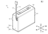
- FIG. 2 is an end view showing a terminal portion and its periphery in the battery device according to the embodiment;
- FIG. FIG. FIG. 2 is a side view of a laminate cell.
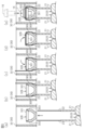
- FIG. 5A to 5E are partial end views showing the connection structure of the electrode terminals.
- FIG. FIG. 4 is a bottom view of the cover portion of the case.
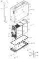
- FIG. 4 is a plan view of the base portion of the case.
- the X-axis of the mutually orthogonal XYZ axes represents the longitudinal direction X of the battery device 10
- the Y-axis represents the width direction Y of the battery device 10
- the Z-axis represents the height direction Z of the battery device 10.
- one side in the longitudinal direction X will be expressed as the "front” and the other side as the "rear”
- one side in the width direction Y will be expressed as the "right” and the other side as the "left”
- one side in the height direction Z will be expressed as the "upper” and the other side as the "lower”.
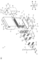
- the battery device 10 has a battery module 11 , a control unit 12 , and a case 13 .
- the battery module 11 has a plurality of laminate cells 20 (seven in this embodiment).
- the laminate cell 20 has a main body 21, a positive electrode terminal 22, and a negative electrode terminal 23.
- the main body 21 has a rectangular plate shape and constitutes a portion in which the positive electrode and the negative electrode are enclosed in a laminate film.
- the positive electrode terminal 22 and the negative electrode terminal 23 are provided at a front end of the main body 21 at intervals in the height direction Z.
- the positive electrode terminal 22 is formed in a thin plate shape from a metal material (e.g., copper).
- the negative electrode terminal 23 is formed in a thin plate shape from a metal material (e.g., aluminum).
- the tip portion of the positive electrode terminal 22 and the tip portion of the negative electrode terminal 23 are each provided with four insertion holes 24 arranged at intervals in the height direction Z.
- the laminate cells 20 are stacked in the width direction Y.
- the laminate cells 20 are connected in series.
- the battery module 11 has a structure in which a positive terminal 22 provided on one of two laminate cells 20 adjacent to each other in the stacking direction is connected to a negative terminal 23 provided on the other laminate cell.
- the battery module 11 has a terminal block 30.
- the terminal block 30 extends along the front end portion of the main body 21 of the laminate cell 20.
- the front end portion of the main body 21 corresponds to a specific outer edge portion where electrode terminals at the outer edge portion of the laminate cell 20, i.e., the positive terminal 22 and the negative terminal 23, are provided.
- the terminal block 30 has, in order from the top, a first protrusion 31, a first terminal block portion 32, an intermediate base 33, a second terminal block portion 34, and a second protrusion 35.
- the first protrusion 31 constitutes an upper end portion of the terminal block 30. When viewed from the longitudinal direction X, the first protrusion 31 protrudes upward to form a stepped shape, a so-called convex shape, with the central portion in the width direction Y protruding upward like the character “convex”.
- the first terminal block portion 32 constitutes a portion of the terminal block 30 that faces the upper one of the two electrode terminals of each laminate cell 20 , that is, the positive terminal 22 and the negative terminal 23 .
- each of the terminal portions 32A to 32D is formed by a first terminal board 301.
- the first terminal board 301 is formed by a rectangular metal plate.
- the first terminal board 301 has four female screw portions 3011 spaced apart in the height direction Z.
- the portions of the terminal block 30 other than the first terminal board 301 are integrally molded from a hard synthetic resin material.
- the first terminal board 301 which is formed by a metal plate, is formed integrally with the portion of the first terminal block portion 32 which is formed by a hard synthetic resin material.
- the first terminal block portion 32 has multiple (seven in this embodiment) slits 303 extending in the height direction Z between each of the terminal portions 32A to 32D.
- a pair of slits 303 is provided for each of the three terminal portions 32B, 32C, and 32D, extending parallel to each other and sandwiching the terminal portions 32B, 32C, and 32D.
- one slit 303 is provided for the terminal portion 32A, extending along the terminal portion 32A.
- the three terminals 32B to 32D are used to connect the electrode terminals of two adjacent laminate cells 20, more specifically, to connect the positive electrode terminal 22 provided on one of the two adjacent laminate cells 20 to the negative electrode terminal 23 provided on the other.
- FIG. 6 shows the connection structure of the electrode terminal in terminal portion 32B.
- the connection structures of the electrode terminals in terminal portions 32B to 32D are the same, so only the connection structure of the electrode terminal in terminal portion 32B will be described here, and a description of the connection structures of the electrode terminals in terminal portions 32C and 32D will be omitted.
- the positive terminal 22 provided on one of the two adjacent laminate cells 20 is inserted into one (the one on the right in the figure) of a pair of slits 303 arranged to sandwich the terminal portion 32B therebetween.
- the negative terminal 23 provided on the other of the two adjacent laminate cells 20 is inserted into the other (the one on the left in the figure) of the pair of slits 303 arranged to sandwich the terminal portion 32B therebetween.
- the tip portion of the positive electrode terminal 22 and the tip portion of the negative electrode terminal 23 are fixed to the front surface of the terminal portion 32B by screw fastening.
- the second terminal plate 302 is used for this fixation.
- the second terminal plate 302 is formed of a rectangular metal plate and has four insertion holes 3021 spaced apart in the height direction Z.
- the tip portion of the positive electrode terminal 22 and the tip portion of the negative electrode terminal 23 are fixed to the terminal portion 32B in a state where they are sandwiched between the first terminal plate 301 and the second terminal plate 302 that constitute the front portion of the terminal portion 32B.
- the tip portion of the positive electrode terminal 22 and the tip portion of the negative electrode terminal 23 are overlapped with each other.
- the overlapping portions of the tip portion of the positive electrode terminal 22 and the tip portion of the negative electrode terminal 23 are in contact with the outer surface of the terminal portion 32B on the side farther from the specific outer edge portion of the laminate cell 20, i.e., the front surface of the terminal portion 32B.
- the tip portion of the positive electrode terminal 22 and the tip portion of the negative electrode terminal 23 are fixed to the terminal portion 32B by screw fastening.
- the positive electrode terminal 22 of the laminate cell 20 arranged at one end in the stacking direction, specifically the left end, is fixed to the terminal portion 32A.
- the positive terminal 22 of the laminate cell 20 is inserted into a slit 303 extending along the terminal portion 32A.
- the positive terminal 22 inserted into the slit 303 is bent to match the inner surface of the slit 303 and the front surface of the terminal portion 32A.
- the tip portion of the positive terminal 22 is fixed to the front surface of the terminal portion 32A by screw fastening. More specifically, the male screw member 16 is screwed into the female screw portion 3011 of the terminal portion 32A in a state where it is inserted into the insertion hole 3021 of the second terminal plate 302 and the insertion hole 24 of the positive terminal 22.
- the second terminal plate 302 used to secure the positive terminal 22 to the terminal portion 32A extends to the fixing portion 33A of the intermediate base 33 (see FIG. 5). This fixing portion 33A will be described later.
- the intermediate base 33 of the terminal block 30 faces a portion of the main body 21 of the laminate cell 20 that is sandwiched between the positive terminal 22 and the negative terminal 23 at the front end portion of the main body 21 .
- the intermediate base 33 has three fixing portions 33A, 33B, and 33C.
- the three fixing portions 33A, 33B, and 33C are spaced apart in the width direction Y.
- Each fixing portion 33A, 33B, and 33C has a rectangular cross section and protrudes forward.
- Each fixing portion 33A, 33B, and 33C has a female screw portion 331.
- the fixing portions 33A, 33B, and 33C are used to fix the second terminal board 302 for the terminal portion 32A, the relay board 122, the second terminal board 302 for the terminal portion 34H, the positive side electric wire 14, and the negative side electric wire 15, all of which will be described later.
- the second terminal block portion 34 of the terminal block 30 constitutes a portion that faces the other of the two electrode terminals of each laminate cell 20 (more specifically, the electrode terminal disposed on the lower side).
- the second terminal block 34 has four terminal portions 34E, 34F, 34G, and 34H.
- Each of the terminal portions 34E to 34H extends in the height direction Z.
- Each of the terminal portions 34E to 34H extends parallel to each other at intervals in the width direction Y.
- the front portions of each of the terminal portions 34E to 34H are formed by the first terminal board 301.
- the first terminal board 301 which is made of a metal plate, is formed integrally with the portion of each of the terminal portions 34E to 34H that is made of a hard synthetic resin material.
- the second terminal block 34 has multiple (seven in this embodiment) slits 303 extending in the longitudinal direction X between each of the terminals 34E to 34H.
- a pair of slits 303 is provided for each of the three terminals 34E, 34F, and 34G, extending parallel to each other and sandwiching the terminals 34E, 34F, and 34G.
- one slit 303 is provided for the terminal 34H, extending along the terminal 34H.
- the three terminals 34E to 34G are used to connect the electrode terminals of two adjacent laminate cells 20, more specifically, to connect the positive electrode terminal 22 provided on one of the two adjacent laminate cells 20 to the negative electrode terminal 23 provided on the other.
- connection structure of the electrode terminals in the terminal portions 34E to 34G is the same as the connection structure of the electrode terminals in the terminal portions 32B to 32D described above (see FIG. 1).
- the tip portion of the positive electrode terminal 22 and the tip portion of the negative electrode terminal 23 are fixed to the terminal portions 34E to 34G in a state where they are sandwiched between the first terminal plate 301 and the second terminal plate 302 that constitute the front portions of the terminal portions 34E to 34G.
- the tip portion of the positive electrode terminal 22 and the tip portion of the negative electrode terminal 23 are overlapped with each other.
- the overlapped portion of the tip portion of the positive electrode terminal 22 and the tip portion of the negative electrode terminal 23 is in contact with the outer surface of the terminal portions 34E to 34G on the side farther from the specific outer edge portion of the laminate cell 20, that is, the front surface of the terminal portions 34E to 34G.
- the tip portion of the positive electrode terminal 22 and the tip portion of the negative electrode terminal 23 are fixed to the terminal portions 34E to 34G (specifically, the first terminal plate 301) by screw fastening.
- the fixing structure of the electrode terminal in the terminal portion 34H is similar to the fixing structure of the electrode terminal in the terminal portion 32A described above (see FIG. 1).
- the negative electrode terminal 23 of the laminate cell 20 arranged at the other end (right end) in the stacking direction is fixed to the terminal portion 34H.
- the negative electrode terminal 23 of the laminate cell 20 is first inserted into a slit 303 extending along the terminal portion 34H. Then, the negative electrode terminal 23 inserted into the slit 303 is bent according to the inner surface of the slit 303 and the outer surface of the terminal portion 34H.
- the tip portion of the negative electrode terminal 23 is fixed to the front surface of the terminal portion 34H by screw fastening. More specifically, the male screw member 16 is screwed into the female screw portion 3011 of the terminal portion 34H (specifically, the first terminal plate 301) in a state where it is inserted into the insertion hole 3021 of the second terminal plate 302 and the insertion hole 24 of the negative electrode terminal 23.
- the second terminal plate 302 used to fix the negative electrode terminal 23 to the terminal portion 34H extends to the fixing portion 33C of the intermediate base 33.
- the second protrusions 35 constitute the lower end portion of the terminal block 30.
- the second protrusions 35 protrude downward to form a rectangular tubular shape.
- the second protrusions 35 are provided at both ends of the lower portion of the terminal block 30 in the width direction Y, one at each end.
- the battery module 11 has a holder 40.
- the holder 40 is for holding rear portions of the plurality of laminate cells 20.
- the holder 40 has a holder body 41 and a third protrusion 43.
- the holder body 41 is in the shape of a rectangular tube and is made up of an upper wall 44, a pair of side walls 45, and a lower wall 46.
- the upper wall 44 extends further forward than the pair of side walls 45 and the lower wall 46.
- the holder 40 is assembled inside the case 13 so that the rear portions of the multiple laminate cells 20 are inserted inside the holder body 41.
- the third protrusion 43 is provided at the rear end of the upper wall 44.
- the third protrusion 43 protrudes upward from the upper surface of the upper wall 44 so as to form a convex shape when viewed from the longitudinal direction X.
- the control unit 12 has a battery management system (hereinafter, referred to as BMS 121 ) and a relay board 122 .
- the BMS 121 is a device for monitoring and managing the state of the battery module 11.
- the BMS 121 is connected to each part of the battery device 10, such as the relay board 122 and each of the terminals 32A-32D, 34E-34H of the terminal block 30.
- the BMS 121 is fixed to the upper surface of the upper wall 44 of the holder 40.
- the relay board 122 is a switching device that switches between a state in which power can be supplied from the battery device 10 to an external device and a state in which the power supply is not possible.
- the relay board 122 is fixed to the fixing parts 33A to 33C of the terminal block 30.
- the other end of the second terminal board 302, one end of which is fixed to the terminal portion 32A, and the relay board 122 are overlapped and fixed to the fixing portion 33A of the terminal block 30 by screw fastening.
- the relay board 122 and one end of the positive side wire 14 are overlapped and fixed to the fixing portion 33B of the terminal block 30 by screw fastening.
- the other end of the second terminal board 302, one end of which is fixed to the terminal portion 34H, the relay board 122, and one end of the negative side wire 15 are overlapped and fixed to the fixing portion 33C of the terminal block 30 by screw fastening.
- the positive electric wire 14 and the negative electric wire 15 extend from the fixing portions 33B, 33C of the terminal block 30 to the outside of the case 13.
- the positive electric wire 14 and the negative electric wire 15 are for connecting the battery device 10 to an external device.
- the case 13 constitutes an exterior member of the battery device 10.
- the case 13 has a rectangular box shape with an outer surface that is a substantially rectangular parallelepiped.
- the battery module 11 and the control unit 12 are housed in the case 13.
- the case 13 has a cover portion 50 and a base portion 60.
- the cover portion 50 has a rectangular cylindrical peripheral wall 51 and a rectangular plate-like top wall 52 that closes an upper opening of the peripheral wall 51.
- Four fixing portions 53 are provided inside the cover portion 50, more specifically, on the inner surface of the peripheral wall 51.
- the fixing portions 53 are provided at the four corners of the lower opening of the cover portion 50.
- Each fixing portion 53 has a female thread portion 531.
- the four fixing portions 53 are used to fix the base portion 60 to the case 13.
- a first recess 54 with a rectangular cross section is formed inside the cover portion 50, more specifically in the front portion of the lower surface of the top wall 52. More specifically, a first protrusion 55 extending in a rectangular shape is provided in the front portion of the lower surface of the top wall 52. The portion surrounded by the first protrusion 55 constitutes the first recess 54.
- This first recess 54 has approximately the same shape as the upper end portion of the first protrusion 31 of the terminal block 30.
- a third recess 56 having a rectangular cross section is formed inside the cover portion 50, more specifically in the rear portion of the lower surface of the top wall 52. More specifically, a third ridge 57 extending in a rectangular shape is provided in the rear portion of the lower surface of the top wall 52. The portion surrounded by this third ridge 57 constitutes the third recess 56.
- This third recess 56 has approximately the same shape as the upper end portion of the third protrusion 43 of the holder 40.
- the base portion 60 has a rectangular plate shape.
- the base portion 60 is shaped to close the lower opening of the cover portion 50.
- through holes 61 are provided that penetrate the base portion 60 in the height direction Z. The through holes 61 are used when fixing the base portion 60 to the cover portion 50.
- a second recess 62 having a rectangular cross section is provided at the front portion of the upper surface of the base portion 60.
- the second recess 62 has a rectangular cross section into which the lower end portions of the two second protrusions 35 of the terminal block 30 fit.
- a fourth recess 64 having a rectangular cross section is provided at the rear portion of the upper surface of the base portion 60. The fourth recess 64 is shaped to fit the lower end portion of the holder 40.
- the battery module 11 When the battery module 11 is assembled to the case 13, the battery module 11 is inserted into the cover section 50. At this time, the first protrusion 31 on the upper part of the terminal block 30 is fitted into the first recess 54 on the top wall 52 of the cover section 50, and the third protrusion 43 on the upper part of the holder 40 is fitted into the third recess 56 on the top wall 52 of the cover section 50.
- one end of the positive side electric wire 14 and one end of the negative side electric wire 15 are connected to the battery module 11, and the other ends of the electric wires 14, 15 are pulled out from the inside to the outside of the cover portion 50.
- the base portion 60 is attached to the cover portion 50 so as to close the lower opening of the cover portion 50 with the seal member 131 sandwiched between the cover portion 50 and the base portion 60.
- the second convex portion 35 at the bottom of the terminal block 30 is fitted into the second concave portion 62 on the top surface of the base portion 60
- the lower end portion of the holder 40 is fitted into the fourth concave portion 64 on the top surface of the base portion 60.
- the base portion 60 is fixed to the cover portion 50 by screw fastening.
- the male screw member 16 is inserted into the through hole 61 of the base portion 60 and screwed into the female screw portion 531 of the fixing portion 53 of the cover portion 50.
- the battery module 11 is supported on the inner surface of the case 13 at four locations: the first convex portion 31 on the upper part of the terminal block 30, the second convex portion 35 on the lower part of the terminal block 30, the third convex portion 43 on the upper part of the holder 40, and the lower end portion of the holder 40.
- the shapes of each part of the battery device 10, specifically the terminal block 30, the holder 40, the cover portion 50, and the base portion 60, are determined so that the multiple laminate cells 20 do not come into contact with the inner surface of the case 13 in this state.
- the battery device 10 includes a battery module 11 and a terminal block 30.
- the battery module 11 has a structure in which a plurality of laminate cells 20 are stacked, and a positive terminal 22 provided on one of adjacent laminate cells 20 is connected to a negative terminal 23 provided on the other.
- the terminal block 30 has terminal portions 32B-32D, 34E-34G used to connect the positive terminal 22 and the negative terminal 23, and extends along the front end portion of the main body portion 21 of the laminate cell 20.
- the positive terminal 22 provided on one of adjacent laminate cells 20 and the negative terminal 23 provided on the other are joined to each other in an overlapped state, with the overlapped portion abutting the front surfaces of the terminal portions 32B-32D, 34E-34G.
- the terminals 22, 23 can be positioned and held firmly by the simple task of pressing the positive terminal 22 of one of the adjacent laminate cells 20 and the negative terminal 23 of the other of the adjacent laminate cells 20 in an overlapping state against the front surface of the terminal portions 32B-32D, 34E-34G. Then, in this state, the positive terminals 22 and the negative terminals 23 can be joined to each other. In this way, the task of connecting the positive terminals 22 and the negative terminals 23 can be easily performed, thereby improving the manufacturing efficiency of the battery device 10.
- the terminal block 30 is provided with a pair of slits 303 extending along the front end portion of the main body 21 of the laminate cell 20 so as to sandwich the terminal portions 32B-32D, 34E-34G, respectively.
- the positive electrode terminal 22 provided on one of the adjacent laminate cells 20 and the negative electrode terminal 23 provided on the other are inserted into the pair of slits 303, respectively.
- the tip portions of the positive electrode terminal 22 and the negative electrode terminal 23 are joined to each other in a state where they are bent toward the terminal portions 32B-32D, 34E-34G so as to follow the inner surface of the slits 303 and the outer surface of the terminal portions 32B-32D, 34E-34G, and are overlapped.
- the positive terminal 22 and the negative terminal 23 can be positioned by simply inserting them into the slits 303 of the terminal block 30 and bending them to fit the inner surface of the slits 303 and the outer surfaces of the terminals 32B-32D, 34E-34G. This improves the manufacturing efficiency of the battery device 10.
- the battery device 10 is equipped with a relay board 122 that switches between a state in which power can be supplied to an external device and a state in which power supply is not possible.
- the relay board 122 is fixed to the terminal block 30.
- the terminal block 30 used to connect the positive terminal 22 and the negative terminal 23 of the laminate cell 20 can also be used as a fixing block for fixing the relay board 122. Therefore, the battery device 10 can have a simpler structure than when a fixing block for the relay board 122 is provided separately from the terminal block 30.
- the relay board 122 can be arranged near the electrode terminals to which it is connected, specifically the positive terminal 22 and the negative terminal 23. Therefore, the connection circuits that connect the relay board 122 and the electrode terminals can be arranged together near the electrode terminals. Therefore, with the above configuration, even though the relay board 122 is provided, the battery device 10 can be prevented from becoming large.
- the battery device 10 includes a holder 40 that holds the rear of the laminated cells 20, and a BMS 121 that manages the state of the battery module 11.
- the BMS 121 is fixed to the holder 40.
- the holder 40 that holds the battery module 11 can also be used as a fixing base for fixing the BMS 121. Therefore, although the holder 40 and the BMS 121 are provided, the battery device 10 can have a simpler structure compared to a case in which a fixing base for the BMS 121 is provided separately from the holder 40.
- the battery device 10 includes a case 13 that constitutes an exterior member, a terminal block 30, and a holder 40.
- the terminal block 30 and the holder 40 are supported on the inner surface of the case 13 with the battery module 11 sandwiched between them so that the battery module 11 does not come into contact with the inner surface of the case 13.
- the battery module 11 can be housed in the case 13 without the battery module 11 coming into contact with the inner surface of the case 13.
- the positive electrode terminal 22 provided on one of the adjacent laminate cells 20 and the negative electrode terminal 23 provided on the other may be inserted into the same slit 303 and fixed to the same terminal portion 32B-32D, 34E-34G.
- one of the pair of slits 303 provided corresponding to each of the terminal portions 32B-32D, 34E-34G may be omitted.
- terminal portions 32A-32D, 34E-34H may be formed from a portion formed from a hard synthetic resin material. In this case, it is also possible to integrally mold the entire terminal block 30, including the front portions of terminal portions 32A-32D, 34E-34H, from a hard synthetic resin material.
- the tip portion of the positive electrode terminal 22 and the tip portion of the negative electrode terminal 23 may be fixed to the front surface of the terminal portions 32B to 32D, 34E to 34G without using the second terminal plate 302.
- the tip portion of the positive electrode terminal 22 and the tip portion of the negative electrode terminal 23 can be joined by screw fastening, or by welding or ultrasonic joining.
- the BMS 121 may be fixed to a part other than the holder 40, such as to the base portion 60 or to a dedicated fixing stand.
- the battery device 10 according to the above embodiment can also be applied to a battery device that does not include a BMS 121.
- a changeover switch or a circuit breaker may be fixed to the terminal block 30.
- the changeover switch or the circuit breaker corresponds to a switching device that switches between a state in which power can be supplied to an external device and a state in which the power supply cannot be supplied.
- the switching device may be fixed to a portion other than the terminal block 30, such as to the base portion 60 or to a dedicated fixing block.
- the battery device 10 according to the above embodiment may also be applied to a battery device that does not include a switching device.
- the battery device 10 according to the above embodiment can also be applied to a battery device in which multiple laminate cells 20 are connected in parallel.
Landscapes
- Chemical & Material Sciences (AREA)
- Chemical Kinetics & Catalysis (AREA)
- Electrochemistry (AREA)
- General Chemical & Material Sciences (AREA)
- Battery Mounting, Suspending (AREA)
- Connection Of Batteries Or Terminals (AREA)
Abstract
バッテリ装置(10)は、バッテリモジュール(11)および端子台(30)を備える。バッテリモジュール(11)は、複数のラミネートセル(20)が積層されるとともに、隣合うラミネートセル(20)の一方に設けられた正極端子(22)と他方に設けられた負極端子(23)とが接続された構造をなす。端子台(30)は、正極端子(22)と負極端子(23)との接続に利用される端子部(32B,32C)を有するとともに、ラミネートセル(20)の本体部(21)の前端部分に沿って延設されている。隣合うラミネートセル(20)の一方に設けられた正極端子(22)と他方に設けられた負極端子(23)とは、重ね合わされた状態で、且つ、当該重ね合わされた部分が端子部(32B,32C)の前面に当接した状態で、(32B,32C)に接合されている。
Description
本開示は、バッテリ装置に関する。
外装材としてラミネートフィルムが用いられてなるラミネートセルが実用されている(特許文献1参照)。また、複数のラミネートセルが積層されるとともに、隣合う2つのラミネートセルの一方に設けられた電極端子と他方に設けられた電極端子とが接続された構造のバッテリモジュールを備えるバッテリ装置も実用されている。
ラミネートセルの電極端子は、銅やアルミニウム等の低剛性の金属材料によって薄い板状に形成される。こうした電極端子は変形し易いため、電極端子同士を接続する際には、同電極端子をその接続に適した所定の形状で保持することが難しい。そのため、電極端子の位置決めを行う作業が煩雑になるなど、同電極端子の接続にかかる作業が煩雑になるおそれがある。したがって、複数のラミネートセルを有して構成されるバッテリ装置の製造効率は低くなり易い。
本開示の一態様では、複数のラミネートセルが積層されるとともに、隣合う前記ラミネートセルの一方に設けられた電極端子と他方に設けられた電極端子とが接続された構造のバッテリモジュールを備えるバッテリ装置が提供される。、バッテリ装置は、前記電極端子の接続に利用される端子部を有するとともに、前記ラミネートセルの外縁部分における前記電極端子が設けられた部分である特定外縁部分に沿って延設される端子台を備える。前記一方に設けられた電極端子と前記他方に設けられた電極端子とは、重ね合わされた状態で、且つ、当該重ね合わされた部分が前記端子部における前記特定外縁部分から遠い側の外面に当接した状態で、互いに接合されている。
以下、図1~図9を参照して、バッテリ装置の一実施形態について説明する。
なお、図面中の互いに直交するXYZ軸におけるX軸は、バッテリ装置10の長手方向Xを表し、Y軸はバッテリ装置10の幅方向Yを表し、Z軸はバッテリ装置10の高さ方向Zを表している。なお、以下の説明では、便宜上、長手方向Xの一方側を「前」、他方側を「後」と表現し、幅方向Yの一方側を「右」、他方側を「左」と表現し、高さ方向Zの一方側を「上」、他方側を「下」と表現する。
なお、図面中の互いに直交するXYZ軸におけるX軸は、バッテリ装置10の長手方向Xを表し、Y軸はバッテリ装置10の幅方向Yを表し、Z軸はバッテリ装置10の高さ方向Zを表している。なお、以下の説明では、便宜上、長手方向Xの一方側を「前」、他方側を「後」と表現し、幅方向Yの一方側を「右」、他方側を「左」と表現し、高さ方向Zの一方側を「上」、他方側を「下」と表現する。
図2および図3に示すように、バッテリ装置10は、バッテリモジュール11、制御部12、およびケース13を有する。
<バッテリモジュール11>
バッテリモジュール11は、複数(本実施形態では、7つ)のラミネートセル20を有する。図4に示すように、ラミネートセル20は、本体部21、正極端子22、負極端子23を有する。本体部21は、矩形板状をなしており、正極および負極をラミネートフィルムで封入した部分を構成している。正極端子22および負極端子23は、本体部21の前端に、高さ方向Zに間隔を置いて設けられている。正極端子22は、金属材料(例えば、銅)によって薄板状に形成されている。負極端子23は、金属材料(例えば、アルミニウム)によって薄板状に形成されている。正極端子22の先端部分および負極端子23の先端部分にはそれぞれ、高さ方向Zに間隔を置いて並ぶ4つの挿通孔24が設けられている。
<バッテリモジュール11>
バッテリモジュール11は、複数(本実施形態では、7つ)のラミネートセル20を有する。図4に示すように、ラミネートセル20は、本体部21、正極端子22、負極端子23を有する。本体部21は、矩形板状をなしており、正極および負極をラミネートフィルムで封入した部分を構成している。正極端子22および負極端子23は、本体部21の前端に、高さ方向Zに間隔を置いて設けられている。正極端子22は、金属材料(例えば、銅)によって薄板状に形成されている。負極端子23は、金属材料(例えば、アルミニウム)によって薄板状に形成されている。正極端子22の先端部分および負極端子23の先端部分にはそれぞれ、高さ方向Zに間隔を置いて並ぶ4つの挿通孔24が設けられている。
図3に示すように、複数のラミネートセル20は、幅方向Yにおいて積層されている。本実施形態のバッテリモジュール11では、複数のラミネートセル20が直列接続されている。詳しくは、バッテリモジュール11は、積層方向において隣合う2つのラミネートセル20の一方に設けられた正極端子22と他方に設けられた負極端子23とが接続された構造をなしている。
<端子台30>
バッテリモジュール11は、端子台30を有する。端子台30は、ラミネートセル20の本体部21の前端部分に沿って延設されている。本実施形態では、本体部21の前端部分が、ラミネートセル20の外縁部分における電極端子、すなわち正極端子22および負極端子23が設けられた部分である特定外縁部分に相当する。図3および図5に示すように、端子台30は、上側から順に、第1凸部31、第1端子台部32、中間ベース33、第2端子台部34、および第2凸部35を有する。
バッテリモジュール11は、端子台30を有する。端子台30は、ラミネートセル20の本体部21の前端部分に沿って延設されている。本実施形態では、本体部21の前端部分が、ラミネートセル20の外縁部分における電極端子、すなわち正極端子22および負極端子23が設けられた部分である特定外縁部分に相当する。図3および図5に示すように、端子台30は、上側から順に、第1凸部31、第1端子台部32、中間ベース33、第2端子台部34、および第2凸部35を有する。
<第1凸部31>
第1凸部31は、端子台30の上端部分を構成している。第1凸部31は、長手方向Xから見て、「凸」の字のように幅方向Yの中央部分が上方に突出した階段形状、いわゆる凸形をなすように上方に突出している。
第1凸部31は、端子台30の上端部分を構成している。第1凸部31は、長手方向Xから見て、「凸」の字のように幅方向Yの中央部分が上方に突出した階段形状、いわゆる凸形をなすように上方に突出している。
<第1端子台部32>
第1端子台部32は、端子台30において、各ラミネートセル20が有する2つの電極端子、すなわち正極端子22および負極端子23のうちの上側に配置される電極端子に対向する部分を構成している。
第1端子台部32は、端子台30において、各ラミネートセル20が有する2つの電極端子、すなわち正極端子22および負極端子23のうちの上側に配置される電極端子に対向する部分を構成している。
図5に示すように、第1端子台部32は、4つの端子部32A,32B,32C,32Dを有する。各端子部32A~32Dは、高さ方向Zに延びている。各端子部32A~32Dは、幅方向Yに間隔を置いて平行に延びている。
図1および図5に示すように、各端子部32A~32Dの前部は、第1端子板301によって構成されている。第1端子板301は、矩形の金属板により構成されている。第1端子板301は、高さ方向Zに間隔を置いて並ぶ4つの雌ねじ部3011を有する。本実施形態では、端子台30における第1端子板301以外の部分は、硬質の合成樹脂材料によって一体成形されている。そして、金属板により構成される第1端子板301は、第1端子台部32における硬質の合成樹脂材料によって構成される部分と一体に形成されている。
図5に示すように、第1端子台部32は、各端子部32A~32Dの間で、高さ方向Zに延びる複数(本実施形態では、7つ)のスリット303を有する。詳しくは、3つの端子部32B,32C,32Dの各々に対しては、同端子部32B,32C,32Dを間に挟んで平行に延びるように、それぞれ一対のスリット303が設けられる。また、端子部32Aに対しては、同端子部32Aに沿って延びる1つのスリット303が設けられる。
本実施形態では、3つの端子部32B~32Dは、隣合う2つのラミネートセル20の電極端子同士の接続、詳しくは、隣合う2つのラミネートセル20の一方に設けられた正極端子22と他方に設けられた負極端子23との接続に利用される。
<電極端子の固定構造>
以下、端子部32B~32Dを利用してラミネートセル20の電極端子同士を接続する接続構造について、図6を参照して説明する。
以下、端子部32B~32Dを利用してラミネートセル20の電極端子同士を接続する接続構造について、図6を参照して説明する。
なお図6は、端子部32Bにおける電極端子の接続構造を示している。本実施形態では、端子部32B~32Dにおける電極端子の接続構造は同一であるため、ここでは端子部32Bにおける電極端子の接続構造についてのみ説明し、端子部32C,32Dにおける電極端子の接続構造についての説明は割愛する。
図6(a)および図6(b)に示すように、電極端子を接続する際には、端子部32Bを間に挟むように配置された一対のスリット303の一方(同図における右側のもの)に、隣合う2つのラミネートセル20の一方に設けられた正極端子22が差し込まれる。また、端子部32Bを間に挟むように配置された一対のスリット303の他方(同図における左側のもの)に、隣合う2つのラミネートセル20の他方に設けられた負極端子23が差し込まれる。これら正極端子22および負極端子23は、各ラミネートセル20の本体部21の前端が端子台30の後端に突き当たる状態(図6(b)に示す状態)になるまで差し込まれる。
その後、図6(c)に示すように、一対のスリット303の一方、具体的には右側のスリット303に挿通された正極端子22が、同スリット303の内面と端子部32Bの前面とに倣って曲げられる。
その後、図6(d)に示すように、一対のスリット303の他方、具体的には左側のスリット303に挿通された負極端子23が、同スリット303の内面と端子部32Bの前面とに倣って曲げられる。このとき、負極端子23は、上記正極端子22の上に重ねられる。
その後、図6(e)に示すように、正極端子22の先端部分と負極端子23の先端部分とが、ねじ締結によって、端子部32Bの前面に固定される。この固定には、第2端子板302が利用される。図3に示すように、第2端子板302は、矩形の金属板によって構成されるとともに、高さ方向Zに間隔を置いて並ぶ4つの挿通孔3021を有する。電極端子同士を接続する際には、雄ねじ部材16が、第2端子板302の挿通孔3021、正極端子22の挿通孔24、および負極端子23の挿通孔24に挿通された状態で、端子部32B(詳しくは、第1端子板301)の雌ねじ部3011に螺合される。これにより、図1および図6(e)に示すように、正極端子22の先端部分と負極端子23の先端部分とは、端子部32Bの前部を構成する第1端子板301と上記第2端子板302との間に挟み込まれた状態で、同端子部32Bに固定される。
本実施形態では、正極端子22の先端部分と負極端子23の先端部分とが、互いに重ね合わされた状態になっている。また、正極端子22の先端部分と負極端子23の先端部分との重ね合わされた部分が、端子部32Bにおけるラミネートセル20の前記特定外縁部分から遠い側の外面、すなわち端子部32Bの前面に当接した状態になっている。そして、その状態で、正極端子22の先端部分と負極端子23の先端部分とが、ねじ締結によって端子部32Bに固定されている。
また本実施形態では、端子部32Aには、積層方向における一方の端、具体的には左端に配置されるラミネートセル20の正極端子22が固定される。
この固定に際しては先ず、端子部32Aに沿って延びるスリット303に、上記ラミネートセル20の正極端子22が差し込まれる。その後、スリット303に挿通された状態の正極端子22が、同スリット303の内面と端子部32Aの前面とに倣って曲げられる。その後、正極端子22の先端部分が、ねじ締結によって、端子部32Aの前面に固定される。詳しくは、雄ねじ部材16が、第2端子板302の挿通孔3021および正極端子22の挿通孔24に挿通された状態で、端子部32Aの雌ねじ部3011に螺合される。
この固定に際しては先ず、端子部32Aに沿って延びるスリット303に、上記ラミネートセル20の正極端子22が差し込まれる。その後、スリット303に挿通された状態の正極端子22が、同スリット303の内面と端子部32Aの前面とに倣って曲げられる。その後、正極端子22の先端部分が、ねじ締結によって、端子部32Aの前面に固定される。詳しくは、雄ねじ部材16が、第2端子板302の挿通孔3021および正極端子22の挿通孔24に挿通された状態で、端子部32Aの雌ねじ部3011に螺合される。
なお、端子部32Aへの正極端子22の固定に利用される第2端子板302は、中間ベース33(図5参照)の固定部33Aまで延びている。この固定部33Aについては後述する。
<中間ベース33>
図3に示すように、端子台30の中間ベース33は、ラミネートセル20の本体部21の前端部分における正極端子22と負極端子23との間に挟まれた部分に対向している。
図3に示すように、端子台30の中間ベース33は、ラミネートセル20の本体部21の前端部分における正極端子22と負極端子23との間に挟まれた部分に対向している。
図5に示すように、中間ベース33は、3つの固定部33A,33B,33Cを有する。3つの固定部33A,33B,33Cは、幅方向Yに間隔を置いて設けられている。各固定部33A,33B,33Cは、断面四角形状で、前側に突出している。各固定部33A,33B,33Cは、雌ねじ部331を有している。固定部33A,33B,33Cは、端子部32A用の第2端子板302や、いずれも後述するリレー基板122、端子部34H用の第2端子板302、プラス側電線14、マイナス側電線15の固定に利用される。
<第2端子台部34>
図3に示すように、端子台30の第2端子台部34は、各ラミネートセル20における2つの電極端子の他方(詳しくは、下側に配置される電極端子)に対向する部分を構成している。
図3に示すように、端子台30の第2端子台部34は、各ラミネートセル20における2つの電極端子の他方(詳しくは、下側に配置される電極端子)に対向する部分を構成している。
図5に示すように、第2端子台部34は、4つの端子部34E,34F,34G,34Hを有する。各端子部34E~34Hは、高さ方向Zに延びている。各端子部34E~34Hは、幅方向Yに間隔を置いて平行に延びている。各端子部34E~34Hの前部は、前記第1端子板301により構成されている。本実施形態では、金属板により構成される第1端子板301が、各端子部34E~34Hにおける硬質の合成樹脂材料によって構成される部分と一体に形成されている。
第2端子台部34は、各端子部34E~34Hの間で、長手方向Xに延びる複数(本実施形態では、7つ)のスリット303を有する。詳しくは、3つの端子部34E,34F,34Gに対しては、同端子部34E,34F,34Gを間に挟んで平行に延びるように、それぞれ一対のスリット303が設けられる。また、端子部34Hに対しては、同端子部34Hに沿って延びる1つのスリット303が設けられる。
本実施形態では、3つの端子部34E~34Gは、隣合う2つのラミネートセル20の電極端子同士の接続、詳しくは、隣合う2つのラミネートセル20の一方に設けられた正極端子22と他方に設けられた負極端子23との接続に利用される。
<電極端子の固定構造>
端子部34E~34Gにおける電極端子の接続構造は、前述した端子部32B~32Dにおける電極端子の接続構造(図1参照)と同一である。詳しくは、正極端子22の先端部分と負極端子23の先端部分とは、端子部34E~34Gの前部を構成する第1端子板301と前記第2端子板302との間に挟み込まれた状態で、同端子部34E~34Gに固定される。
端子部34E~34Gにおける電極端子の接続構造は、前述した端子部32B~32Dにおける電極端子の接続構造(図1参照)と同一である。詳しくは、正極端子22の先端部分と負極端子23の先端部分とは、端子部34E~34Gの前部を構成する第1端子板301と前記第2端子板302との間に挟み込まれた状態で、同端子部34E~34Gに固定される。
本実施形態では、正極端子22の先端部分と負極端子23の先端部分とが、互いに重ね合わされた状態になっている。また、正極端子22の先端部分と負極端子23の先端部分との重ね合わされた部分が、端子部34E~34Gにおけるラミネートセル20の前記特定外縁部分から遠い側の外面、すなわち端子部34E~34Gの前面に当接した状態になっている。そして、その状態で、正極端子22の先端部分と負極端子23の先端部分とが、端子部34E~34G(詳しくは、第1端子板301)に、ねじ締結によって固定されている。
端子部34Hにおける電極端子の固定構造は、前述した端子部32Aにおける電極端子の固定構造(図1参照)と同様である。
図3および図5に示すように、本実施形態では、端子部34Hには、積層方向における他方の端(右端)に配置されるラミネートセル20の負極端子23が固定される。この固定に際しては先ず、端子部34Hに沿って延びるスリット303に、上記ラミネートセル20の負極端子23が差し込まれる。その後、スリット303に挿通された状態の負極端子23が、同スリット303の内面と端子部34Hの外面とに倣って曲げられる。その後、負極端子23の先端部分が、ねじ締結によって、端子部34Hの前面に固定される。より詳しくは、雄ねじ部材16が、第2端子板302の挿通孔3021および負極端子23の挿通孔24に挿通された状態で、端子部34H(詳しくは、第1端子板301)の雌ねじ部3011に螺合される。なお本実施形態では、端子部34Hへの負極端子23の固定に利用される第2端子板302は、中間ベース33の固定部33Cまで延びている。
図3および図5に示すように、本実施形態では、端子部34Hには、積層方向における他方の端(右端)に配置されるラミネートセル20の負極端子23が固定される。この固定に際しては先ず、端子部34Hに沿って延びるスリット303に、上記ラミネートセル20の負極端子23が差し込まれる。その後、スリット303に挿通された状態の負極端子23が、同スリット303の内面と端子部34Hの外面とに倣って曲げられる。その後、負極端子23の先端部分が、ねじ締結によって、端子部34Hの前面に固定される。より詳しくは、雄ねじ部材16が、第2端子板302の挿通孔3021および負極端子23の挿通孔24に挿通された状態で、端子部34H(詳しくは、第1端子板301)の雌ねじ部3011に螺合される。なお本実施形態では、端子部34Hへの負極端子23の固定に利用される第2端子板302は、中間ベース33の固定部33Cまで延びている。
<第2凸部35>
第2凸部35は、端子台30の下端部分を構成している。第2凸部35は、矩形筒状をなすように下方に突出している。第2凸部35は、端子台30の下部における幅方向Yの両端に1つずつ設けられている。
第2凸部35は、端子台30の下端部分を構成している。第2凸部35は、矩形筒状をなすように下方に突出している。第2凸部35は、端子台30の下部における幅方向Yの両端に1つずつ設けられている。
<ホルダ40>
図3および図7に示すように、バッテリモジュール11は、ホルダ40を有している。ホルダ40は、複数のラミネートセル20の後部を保持するためのものである。ホルダ40は、ホルダ本体41と第3凸部43とを有する。
図3および図7に示すように、バッテリモジュール11は、ホルダ40を有している。ホルダ40は、複数のラミネートセル20の後部を保持するためのものである。ホルダ40は、ホルダ本体41と第3凸部43とを有する。
ホルダ本体41は、上壁44、一対の側壁45、および下壁46からなる四角筒状をなしている。上壁44は、一対の側壁45および下壁46よりも、前方に延長されている。本実施形態では、ホルダ本体41の内部に複数のラミネートセル20の後部が挿通された状態になるように、ホルダ40はケース13の内部に組み付けられる。
第3凸部43は、上壁44の後端に設けられる。第3凸部43は、長手方向Xから見て凸形をなすように、上壁44の上面から上方に突出している。
<制御部12>
制御部12は、バッテリマネジメントシステム(以下、BMS121)およびリレー基板122を有する。
<制御部12>
制御部12は、バッテリマネジメントシステム(以下、BMS121)およびリレー基板122を有する。
BMS121は、バッテリモジュール11の状態を監視するとともに管理するための装置である。BMS121は、リレー基板122や、端子台30の各端子部32A~32D,34E~34Hなど、バッテリ装置10の各部に接続されている。BMS121は、ホルダ40の上壁44における上面に固定されている。
リレー基板122は、バッテリ装置10から外部機器への電力供給が可能になる状態と同電力供給が不能になる状態とを切り替えるための切替装置である。リレー基板122は、端子台30の固定部33A~33Cに固定される。
本実施形態では、端子台30の固定部33Aには、一端が端子部32Aに固定された第2端子板302の他端とリレー基板122とが重ね合わされた状態で、ねじ締結によって固定されている。また、端子台30の固定部33Bには、リレー基板122とプラス側電線14の一端とが重ね合わされた状態で、ねじ締結によって固定されている。端子台30の固定部33Cには、一端が端子部34Hに固定された第2端子板302の他端と、リレー基板122と、マイナス側電線15の一端とが重ね合わされた状態でねじ締結によって固定されている。
図2に示すように、本実施形態では、上記プラス側電線14およびマイナス側電線15は、端子台30の固定部33B,33Cからケース13の外部まで延びている。プラス側電線14およびマイナス側電線15は、バッテリ装置10と外部機器とを接続するためのものである。
<ケース13>
図2および図7に示すように、ケース13は、バッテリ装置10の外装部材を構成するものである。ケース13は、外面が略直方体をなす矩形箱状をなしている。バッテリモジュール11および制御部12は、ケース13に収容されている。ケース13は、カバー部50およびベース部60を有する。
図2および図7に示すように、ケース13は、バッテリ装置10の外装部材を構成するものである。ケース13は、外面が略直方体をなす矩形箱状をなしている。バッテリモジュール11および制御部12は、ケース13に収容されている。ケース13は、カバー部50およびベース部60を有する。
<カバー部50>
図7および図8に示すように、カバー部50は、四角筒状の周壁51と、周壁51の上部開口を塞ぐ矩形板状の天壁52とを有する。カバー部50の内部、詳しくは周壁51の内面には、4つの固定部53が設けられている。固定部53は、カバー部50の下部開口の四隅に設けられている。各固定部53は、雌ねじ部531を有する。4つの固定部53は、ケース13へのベース部60の固定に用いられる。
図7および図8に示すように、カバー部50は、四角筒状の周壁51と、周壁51の上部開口を塞ぐ矩形板状の天壁52とを有する。カバー部50の内部、詳しくは周壁51の内面には、4つの固定部53が設けられている。固定部53は、カバー部50の下部開口の四隅に設けられている。各固定部53は、雌ねじ部531を有する。4つの固定部53は、ケース13へのベース部60の固定に用いられる。
カバー部50の内部、詳しくは天壁52の下面における前側の部分には、断面長方形状の第1凹部54が形成されている。詳しくは、天壁52の下面における前側の部分には、長方形状をなすように延びる第1突条55が設けられている。第1突条55により囲まれた部分が第1凹部54を構成している。この第1凹部54は、端子台30の第1凸部31の上端部分と略同一の形状をなしている。
また、カバー部50の内部、詳しくは天壁52の下面における後ろ側の部分には、断面長方形状の第3凹部56が形成されている。詳しくは、天壁52の下面における後ろ側の部分には、長方形状をなすように延びる第3突条57が設けられている。この第3突条57により囲まれた部分が第3凹部56を構成している。この第3凹部56は、ホルダ40の第3凸部43の上端部分と略同一の形状をなしている。
<ベース部60>
図7および図9に示すように、ベース部60は、矩形板状をなしている。ベース部60は、カバー部50の下部開口を塞ぐ形状をなしている。ベース部60の四隅には、同ベース部60を高さ方向Zに貫通する貫通孔61が設けられている。この貫通孔61は、ベース部60をカバー部50に固定する際に利用される。ベース部60の上面における前側の部分には、断面長方形状の第2凹部62が設けられている。第2凹部62は、端子台30における2つの第2凸部35の下端部分が嵌まる断面長方形状をなしている。ベース部60の上面における後ろ側の部分には、断面長方形状の第4凹部64が設けられている。この第4凹部64は、ホルダ40の下端部分が嵌まる形状をなしている。
図7および図9に示すように、ベース部60は、矩形板状をなしている。ベース部60は、カバー部50の下部開口を塞ぐ形状をなしている。ベース部60の四隅には、同ベース部60を高さ方向Zに貫通する貫通孔61が設けられている。この貫通孔61は、ベース部60をカバー部50に固定する際に利用される。ベース部60の上面における前側の部分には、断面長方形状の第2凹部62が設けられている。第2凹部62は、端子台30における2つの第2凸部35の下端部分が嵌まる断面長方形状をなしている。ベース部60の上面における後ろ側の部分には、断面長方形状の第4凹部64が設けられている。この第4凹部64は、ホルダ40の下端部分が嵌まる形状をなしている。
<ケース13内におけるバッテリモジュール11の保持構造>
図2、図3および図7に示すように、本実施形態では、端子台30およびホルダ40は、バッテリモジュール11を間に挟んだ状態で、同バッテリモジュール11がケース13の内面に接触しないように同ケース13の内面に支持されている。
図2、図3および図7に示すように、本実施形態では、端子台30およびホルダ40は、バッテリモジュール11を間に挟んだ状態で、同バッテリモジュール11がケース13の内面に接触しないように同ケース13の内面に支持されている。
バッテリモジュール11をケース13に組み付ける際には、同バッテリモジュール11がカバー部50内に挿入される。このとき、端子台30の上部の第1凸部31がカバー部50の天壁52の第1凹部54に嵌められるとともに、ホルダ40の上部の第3凸部43が、カバー部50の天壁52の第3凹部56に嵌められる。
なお本実施形態では、バッテリモジュール11のカバー部50への挿入に先立ち、プラス側電線14およびマイナス側電線15の一端がバッテリモジュール11に接続されるとともに、それら電線14,15の他端がカバー部50の内部から外部に引き出される。
また、バッテリモジュール11をケース13に組み付ける際には、カバー部50とベース部60との間にシール部材131を挟んだ状態で、カバー部50の下部開口を塞ぐように、同カバー部50にベース部60が取り付けられる。このときには、端子台30の下部の第2凸部35がベース部60の上面の第2凹部62に嵌められており、ホルダ40の下端部分がベース部60の上面の第4凹部64に嵌められている。そして、この状態で、ベース部60がカバー部50にねじ締結によって固定される。具体的には、雄ねじ部材16が、ベース部60の貫通孔61に挿通された状態で、カバー部50の固定部53の雌ねじ部531に螺合される。
本実施形態では、バッテリモジュール11は、端子台30上部の第1凸部31、同端子台30下部の第2凸部35、ホルダ40上部の第3凸部43、および同ホルダ40の下端部分の4箇所において、ケース13の内面に支持されている。本実施形態では、この状態において複数のラミネートセル20がケース13の内面に接触しないように、バッテリ装置10の各部、詳しくは、端子台30、ホルダ40、カバー部50、およびベース部60の形状が定められている。
<作用効果>
本実施形態の作用および効果について説明する。
(1)バッテリ装置10は、バッテリモジュール11および端子台30を備える。バッテリモジュール11は、複数のラミネートセル20が積層されるとともに、隣合うラミネートセル20の一方に設けられた正極端子22と他方に設けられた負極端子23とが接続された構造をなす。端子台30は、正極端子22と負極端子23との接続に利用される端子部32B~32D,34E~34Gを有するとともに、ラミネートセル20の本体部21の前端部分に沿って延設されている。隣合うラミネートセル20の一方に設けられた正極端子22と他方に設けられた負極端子23とは、重ね合わされた状態で、且つ、当該重ね合わされた部分が端子部32B~32D,34E~34Gの前面に当接した状態で、互いに接合されている。
本実施形態の作用および効果について説明する。
(1)バッテリ装置10は、バッテリモジュール11および端子台30を備える。バッテリモジュール11は、複数のラミネートセル20が積層されるとともに、隣合うラミネートセル20の一方に設けられた正極端子22と他方に設けられた負極端子23とが接続された構造をなす。端子台30は、正極端子22と負極端子23との接続に利用される端子部32B~32D,34E~34Gを有するとともに、ラミネートセル20の本体部21の前端部分に沿って延設されている。隣合うラミネートセル20の一方に設けられた正極端子22と他方に設けられた負極端子23とは、重ね合わされた状態で、且つ、当該重ね合わされた部分が端子部32B~32D,34E~34Gの前面に当接した状態で、互いに接合されている。
上記構成によれば、端子部32B~32D,34E~34Gの前面に、隣合うラミネートセル20の一方の正極端子22と他方の負極端子23とを重ね合わせた状態で押し付けるといった容易な作業で、端子22,23を位置決めしつつしっかりと保持できる。そして、この状態で、それら正極端子22と負極端子23とを互いに接合することができる。このように、正極端子22と負極端子23とを接続する作業を容易に行うことができるため、バッテリ装置10の製造効率を向上させることができる。
(2)端子台30には、端子部32B~32D,34E~34Gの各々に対して、同端子部32B~32D,34E~34Gを間に挟むようにラミネートセル20の本体部21の前端部分に沿って延びる一対のスリット303が設けられている。一対のスリット303には、隣合うラミネートセル20の一方に設けられた正極端子22と他方に設けられた負極端子23とが各別に挿通される。正極端子22および負極端子23の先端部分は、各々が上記スリット303の内面および端子部32B~32D,34E~34Gの外面に沿うように同端子部32B~32D,34E~34Gに向けて曲がった状態、且つ、重ね合わされた状態で互いに接合される。
上記構成によれば、正極端子22や負極端子23を端子台30のスリット303に挿通するとともにスリット303の内面と端子部32B~32D,34E~34Gの外面とに倣って曲げるといった簡単な作業で、端子22,23の位置決めを行うことができる。これにより、バッテリ装置10の製造効率を向上させることができる。
(3)バッテリ装置10は、外部機器への電力供給が可能になる状態と同電力供給が不能になる状態とを切り替えるリレー基板122を備える。リレー基板122は、端子台30に固定される。
上記構成によれば、ラミネートセル20の正極端子22や負極端子23の接続に利用する端子台30を、リレー基板122の固定用の固定台としても利用することができる。そのため、端子台30とは別にリレー基板122用の固定台が設けられる場合と比較して、バッテリ装置10を簡素な構造にすることができる。また、リレー基板122を、その接続対象である電極端子、詳しくは正極端子22や負極端子23の近傍に配置することができる。そのため、リレー基板122と電極端子とを接続する接続回路を同電極端子の近傍にまとめて配置することができる。したがって上記構成によれば、リレー基板122が設けられるとはいえ、バッテリ装置10の大型化を抑えることができる。
(4)バッテリ装置10は、複数のラミネートセル20の後部を保持するホルダ40と、バッテリモジュール11の状態を管理するBMS121とを備える。BMS121は、ホルダ40に固定されている。
上記構成によれば、バッテリモジュール11を保持するホルダ40を、BMS121の固定用の固定台としても用いることができる。そのため、ホルダ40やBMS121が設けられるとはいえ、ホルダ40とは別にBMS121用の固定台が設けられる場合と比較して、バッテリ装置10を簡素な構造にすることができる。
(5)バッテリ装置10は、外装部材を構成するケース13と、端子台30と、ホルダ40とを備える。端子台30およびホルダ40は、バッテリモジュール11がケース13の内面に接触しないように同バッテリモジュール11を間に挟んだ状態で、ケース13の内面に支持される。
上記構成によれば、電極端子の接続用の端子台30とバッテリモジュール11の保持用のホルダ40とを利用することで、バッテリモジュール11がケース13内面に接触しない状態で、同バッテリモジュール11をケース13内に収容することができる。
<変更例>
なお、上記実施形態は、以下のように変更して実施することができる。上記実施形態および以下の変更例は、技術的に矛盾しない範囲で互いに組み合わせて実施することができる。
なお、上記実施形態は、以下のように変更して実施することができる。上記実施形態および以下の変更例は、技術的に矛盾しない範囲で互いに組み合わせて実施することができる。
・隣合うラミネートセル20の一方に設けられた正極端子22と他方に設けられた負極端子23とを、同一のスリット303に挿通するとともに、同一の端子部32B~32D,34E~34Gに固定するようにしてもよい。この場合には、端子部32B~32D,34E~34Gの各々に対応して設けられる一対のスリット303のうちの一方を省略することができる。
・端子部32A~32D,34E~34Hの前部を、金属板により形成された第1端子板301によって構成することに代えて、硬質の合成樹脂材料により形成された部分によって構成するようにしてもよい。この場合には、端子部32A~32D,34E~34Hの前部を含む端子台30の全体を、硬質の合成樹脂材料によって一体成形することなども可能である。
・正極端子22の先端部分と負極端子23の先端部分とを、第2端子板302を用いることなく、端子部32B~32D,34E~34Gの前面に固定するようにしてもよい。
・端子部32B~32D,34E~34Gにおいて、正極端子22の先端部分と負極端子23の先端部分とを、ねじ締結によって接合することの他、溶接によって接合したり、超音波接合によって接合したりすることができる。
・端子部32B~32D,34E~34Gにおいて、正極端子22の先端部分と負極端子23の先端部分とを、ねじ締結によって接合することの他、溶接によって接合したり、超音波接合によって接合したりすることができる。
・BMS121を、ベース部60に固定したり専用の固定台に固定したりするなど、ホルダ40以外の部分に固定してもよい。
・上記実施形態にかかるバッテリ装置10は、BMS121を備えていないバッテリ装置にも適用することができる。
・上記実施形態にかかるバッテリ装置10は、BMS121を備えていないバッテリ装置にも適用することができる。
・リレー基板122に代えて、切替スイッチや遮断器を端子台30に固定するようにしてもよい。この場合には、切替スイッチや遮断器が、外部機器への電力供給が可能になる状態と同電力供給が不能になる状態とを切り替える切替装置に相当する。
・切替装置を、ベース部60に固定したり専用の固定台に固定したりするなど、端子台30以外の部分に固定するようにしてもよい。
・上記実施形態にかかるバッテリ装置10は、切替装置を備えていないバッテリ装置にも適用することができる。
・上記実施形態にかかるバッテリ装置10は、切替装置を備えていないバッテリ装置にも適用することができる。
・上記実施形態にかかるバッテリ装置10は、複数のラミネートセル20が並列接続されるタイプのバッテリ装置にも適用することができる。
Claims (5)
- 複数のラミネートセルが積層されるとともに、隣合う前記ラミネートセルの一方に設けられた電極端子と他方に設けられた電極端子とが接続された構造のバッテリモジュールを備えるバッテリ装置において、
前記電極端子の接続に利用される端子部を有するとともに、前記ラミネートセルの外縁部分における前記電極端子が設けられた部分である特定外縁部分に沿って延設される端子台を備え、
前記一方に設けられた電極端子と前記他方に設けられた電極端子とは、重ね合わされた状態で、且つ、当該重ね合わされた部分が前記端子部における前記特定外縁部分から遠い側の外面に当接した状態で、互いに接合されている、
バッテリ装置。 - 前記端子台は、前記端子部を間に挟むように前記特定外縁部分に沿って延びる一対のスリットを有し、
前記一対のスリットには、前記一方に設けられた電極端子と前記他方に設けられた電極端子とが各別に挿通されており、
前記一対のスリットに各別に挿通された2つの前記電極端子の先端部分は、各々が前記スリットの内面および前記端子部の外面に沿うように同端子部に向けて曲がった状態、且つ、重ね合わされた状態で、互いに接合されている、
請求項1に記載のバッテリ装置。 - 外部機器への電力供給が可能になる状態と同電力供給が不能になる状態とを切り替える切替装置を備え、
前記切替装置は、前記端子台に固定されている、
請求項1または2に記載のバッテリ装置。 - 前記バッテリモジュールを保持するホルダと、前記バッテリモジュールの状態を管理するバッテリマネジメントシステムと、を備え、
前記バッテリマネジメントシステムは、前記ホルダに固定されている、
請求項1~3のいずれか一つに記載のバッテリ装置。 - 外装部材を構成するケースと、前記バッテリモジュールを保持するホルダと、を備え、
前記ホルダおよび前記端子台は、前記バッテリモジュールが前記ケースの内面に接触しないように同バッテリモジュールを間に挟んだ状態で、前記ケースの内面に支持されている、
請求項1~4のいずれか一つに記載のバッテリ装置。
Applications Claiming Priority (2)
| Application Number | Priority Date | Filing Date | Title |
|---|---|---|---|
| JP2023204026A JP2025089064A (ja) | 2023-12-01 | 2023-12-01 | バッテリ装置 |
| JP2023-204026 | 2023-12-01 |
Publications (1)
| Publication Number | Publication Date |
|---|---|
| WO2025115252A1 true WO2025115252A1 (ja) | 2025-06-05 |
Family
ID=95896664
Family Applications (1)
| Application Number | Title | Priority Date | Filing Date |
|---|---|---|---|
| PCT/JP2024/017694 Pending WO2025115252A1 (ja) | 2023-12-01 | 2024-05-13 | バッテリ装置 |
Country Status (2)
| Country | Link |
|---|---|
| JP (1) | JP2025089064A (ja) |
| WO (1) | WO2025115252A1 (ja) |
Citations (3)
| Publication number | Priority date | Publication date | Assignee | Title |
|---|---|---|---|---|
| JP2019057483A (ja) * | 2017-09-22 | 2019-04-11 | 株式会社デンソー | 制御モジュール |
| JP2020521288A (ja) * | 2017-11-30 | 2020-07-16 | エルジー・ケム・リミテッド | バスバーアセンブリーを備えたバッテリーモジュール |
| JP2023045893A (ja) * | 2021-09-22 | 2023-04-03 | 本田技研工業株式会社 | バッテリユニット |
-
2023
- 2023-12-01 JP JP2023204026A patent/JP2025089064A/ja active Pending
-
2024
- 2024-05-13 WO PCT/JP2024/017694 patent/WO2025115252A1/ja active Pending
Patent Citations (3)
| Publication number | Priority date | Publication date | Assignee | Title |
|---|---|---|---|---|
| JP2019057483A (ja) * | 2017-09-22 | 2019-04-11 | 株式会社デンソー | 制御モジュール |
| JP2020521288A (ja) * | 2017-11-30 | 2020-07-16 | エルジー・ケム・リミテッド | バスバーアセンブリーを備えたバッテリーモジュール |
| JP2023045893A (ja) * | 2021-09-22 | 2023-04-03 | 本田技研工業株式会社 | バッテリユニット |
Also Published As
| Publication number | Publication date |
|---|---|
| JP2025089064A (ja) | 2025-06-12 |
Similar Documents
| Publication | Publication Date | Title |
|---|---|---|
| US9812694B2 (en) | Electrode member and battery block | |
| CN107851767B (zh) | 电源装置及电池单元用汇流条 | |
| EP2325917B1 (en) | Battery assembly | |
| US20200044208A1 (en) | Battery module and electricity storage unit | |
| JP6995882B2 (ja) | 電池モジュール | |
| JP7295096B2 (ja) | 電池パック | |
| US11245152B2 (en) | Battery pack | |
| WO2014034351A1 (ja) | 蓄電装置 | |
| JP7081237B2 (ja) | 接続モジュール、および蓄電モジュール | |
| KR20200069720A (ko) | 인서트 사출된 버스바 조립체를 포함하는 전지 모듈 | |
| CN110832670B (zh) | 电池组及其制造方法 | |
| KR102056366B1 (ko) | 전지팩의 셀 모듈 및 그 조립 방법 | |
| US11502361B2 (en) | Energy storage apparatus | |
| JP2013243061A (ja) | 電池モジュール | |
| JP2019117732A (ja) | 蓄電装置 | |
| JP3619765B2 (ja) | パック電池 | |
| JP2014022238A (ja) | 電池パック | |
| JP2014022239A (ja) | 電池パック | |
| WO2025115252A1 (ja) | バッテリ装置 | |
| JP7307721B2 (ja) | バッテリパック | |
| JP2000323109A (ja) | 電池モジュール | |
| JP2023014626A (ja) | 蓄電装置 | |
| JP2018010836A (ja) | 蓄電装置及びその製造方法 | |
| CN206271802U (zh) | 电池导片镭焊结构 | |
| JP2022149361A (ja) | 電池パック |
Legal Events
| Date | Code | Title | Description |
|---|---|---|---|
| 121 | Ep: the epo has been informed by wipo that ep was designated in this application |
Ref document number: 24896944 Country of ref document: EP Kind code of ref document: A1 |