WO2025115161A1 - 折損判定装置、及びコンピュータが読み取り可能な記憶媒体 - Google Patents
折損判定装置、及びコンピュータが読み取り可能な記憶媒体 Download PDFInfo
- Publication number
- WO2025115161A1 WO2025115161A1 PCT/JP2023/042856 JP2023042856W WO2025115161A1 WO 2025115161 A1 WO2025115161 A1 WO 2025115161A1 JP 2023042856 W JP2023042856 W JP 2023042856W WO 2025115161 A1 WO2025115161 A1 WO 2025115161A1
- Authority
- WO
- WIPO (PCT)
- Prior art keywords
- sample
- change
- time period
- probability
- cutting time
- Prior art date
- Legal status (The legal status is an assumption and is not a legal conclusion. Google has not performed a legal analysis and makes no representation as to the accuracy of the status listed.)
- Pending
Links
Images






Classifications
-
- B—PERFORMING OPERATIONS; TRANSPORTING
- B23—MACHINE TOOLS; METAL-WORKING NOT OTHERWISE PROVIDED FOR
- B23Q—DETAILS, COMPONENTS, OR ACCESSORIES FOR MACHINE TOOLS, e.g. ARRANGEMENTS FOR COPYING OR CONTROLLING; MACHINE TOOLS IN GENERAL CHARACTERISED BY THE CONSTRUCTION OF PARTICULAR DETAILS OR COMPONENTS; COMBINATIONS OR ASSOCIATIONS OF METAL-WORKING MACHINES, NOT DIRECTED TO A PARTICULAR RESULT
- B23Q17/00—Arrangements for observing, indicating or measuring on machine tools
- B23Q17/09—Arrangements for observing, indicating or measuring on machine tools for indicating or measuring cutting pressure or for determining cutting-tool condition, e.g. cutting ability, load on tool
-
- G—PHYSICS
- G05—CONTROLLING; REGULATING
- G05B—CONTROL OR REGULATING SYSTEMS IN GENERAL; FUNCTIONAL ELEMENTS OF SUCH SYSTEMS; MONITORING OR TESTING ARRANGEMENTS FOR SUCH SYSTEMS OR ELEMENTS
- G05B19/00—Program-control systems
- G05B19/02—Program-control systems electric
- G05B19/18—Numerical control [NC], i.e. automatically operating machines, in particular machine tools, e.g. in a manufacturing environment, so as to execute positioning, movement or co-ordinated operations by means of program data in numerical form
- G05B19/406—Numerical control [NC], i.e. automatically operating machines, in particular machine tools, e.g. in a manufacturing environment, so as to execute positioning, movement or co-ordinated operations by means of program data in numerical form characterised by monitoring or safety
- G05B19/4065—Monitoring tool breakage, life or condition
Definitions
- the present disclosure relates to a breakage determination device and a computer-readable storage medium.
- Patent Document 1 In devices that detect or predict breakage of tools used in machine tools, there is technology that multiplies the characteristic amount of the load during the cutting time period by a coefficient to calculate a fluctuating threshold value and determine breakage. For example, see Patent Document 1.
- Patent Document 1 requires trial machining, so breakage cannot be determined from the first machining.
- the breakage detection device includes a data acquisition unit that acquires the load value applied to the axis of the machine tool as a sample, a determination unit that determines whether the sample acquired by the data acquisition unit is a sample detected during a cutting time period or a sample detected during a non-cutting time period, a change amount calculation unit that calculates the amount of change in the sample during the cutting time period, a probability calculation unit that excludes one or more of the change amounts and calculates a probability density function from the remaining change amounts, and a breakage detection unit that determines whether the tool is broken based on the probability of occurrence of the excluded change amount in the probability density function.
- FIG. 2 is a block diagram of a breakage determination device.
- 13 is a graph showing a change in a command during cutting.
- 13 is a graph of a sample under normal conditions.
- 13 is a graph of a sample when a tool breaks during cutting.
- 13 is a graph showing the relationship between a probability density function and an excluded amount of change.
- 1 is a graph of normal samples and a table showing values in the 3 ⁇ interval when one point is excluded.
- 13 is a graph of samples when a tool breaks during cutting, and a table showing values in the 3 ⁇ interval when one point is excluded.
- 4 is a flowchart illustrating an operation of the breakage determination device.
- FIG. 13 is a block diagram of a modified example of the breakage determination device.
- FIG. 2 is a hardware configuration diagram of the breakage determination device.
- the breakage detection device is described below.
- the breakage detection device is realized by an information processing device such as a numerical control device or a PC (personal computer).
- FIG. 1 is a block diagram of a breakage determination device 100.
- the breakage determination device 100 includes a data acquisition unit 10, a determination unit 11, a change amount calculation unit 12, a probability calculation unit 13, and a breakage detection unit 14.
- the data acquisition unit 10 acquires at least one of the loads of the main shaft and the feed shaft.
- the load value will be referred to as a sample.
- the determination unit 11 determines whether the sample acquired by the data acquisition unit 10 is a sample detected during a cutting time period or a sample detected during a non-cutting time period.
- a cutting time period is a time period during which the tool is cutting a workpiece.
- a non-cutting time period is a time period during which the tool is not cutting a workpiece.
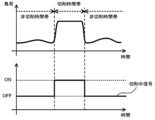
- One method of determination is to detect a signal. For example, during cutting time periods, a "cutting" command signal is output from the numerical control device. An example of a "cutting" command signal is shown in Figure 2.
- the upper graph in Figure 2 shows the load value
- the lower graph in Figure 2 shows the "cutting" command signal.
- the change amount calculation unit 12 calculates the amount of change in the samples acquired during the cutting time period.
- the amount of change in the samples is the increase or decrease in the value of the samples.
- the change amount calculation unit 12 calculates the sample difference by subtracting the value of the sample at a certain point in time from the value of the sample before or after that point in time.
- 3 is a graph showing the change in the samples during normal operation (when the tool is not broken). During normal operation, the sample values during the cutting period are approximately constant. The amount of change in the samples does not fluctuate significantly.
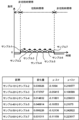
- Figure 4 shows the changes in samples when a tool breaks during cutting. For the sake of explanation, a small number of samples (5 points) are shown in Figure 4. It is assumed that the actual number of samples is sufficiently large.
- the change amount calculation unit 12 calculates the change amount of the samples. The change amount from sample 1 to sample 2 is "0", the change amount from sample 2 to sample 3 is "+0.2", the change amount from sample 3 to sample 4 is "-1.5", and the change amount from sample 4 to sample 5 is "-0.1".
- the change amount calculation unit 12 calculates a sufficient number of change amounts.
- the probability calculation unit 13 calculates a probability density function of the amount of change.
- the probability calculation unit 13 executes pre-processing. In the pre-processing, a part of the amount of change is excluded from the sample.
- the probability calculation unit 13 excludes values with large absolute values. In other words, values with large changes are excluded regardless of whether they are positive or negative.
- the number of values to be excluded may be one or more.
- the criterion for exclusion may be the order of magnitude of change, or a threshold value may be used.
- the breakage detection unit 14 uses a probability density function of the sample change amount to determine the probability of occurrence of the excluded value, and determines that the tool is broken if the probability of occurrence of the excluded value is sufficiently small.
- Fig. 5 is a graph showing the relationship between a probability density function calculated from the remaining amounts of change after excluding some of the amounts of change, and the probability of occurrence of the excluded amounts of change.
- the normal distribution on the right side is the probability density function
- the points on the left side are the amounts of change that have been excluded.
- Figure 6 shows samples under normal conditions (when not broken). The values of Sample 1 to Sample 6 do not change much. Specifically, the change from Sample 1 to Sample 2 is "0.036926", the change from Sample 2 to Sample 3 is "0.173767”, the change from Sample 3 to Sample 4 is "0.014832”, the change from Sample 4 to Sample 5 is "0.046814", the change from Sample 5 to Sample 6 is "0.006226”, and the change from Sample 6 to Sample 7 is "0.031311".
- Figure 6 lists the "3 ⁇ intervals" when each amount of change is excluded.
- ⁇ -3 ⁇ is “-0.1094" and “ ⁇ +3 ⁇ ” is “0.218577”.
- ⁇ -3 ⁇ is "-0.05415" and “ ⁇ +3 ⁇ ” is "0.108589”.
- ⁇ -3 ⁇ is "-0.11801” and " ⁇ +3 ⁇ ” is "0.236033”.
- ⁇ -3 ⁇ is "-0.10553” and " ⁇ +3 ⁇ " is "0.21075".
- Figure 7 shows samples when the tool breaks during cutting.
- the values from sample 1 to sample 6 change rapidly. Specifically, the change from sample 1 to sample 2 is "0.032484", the change from sample 2 to sample 3 is "0.128205”, the change from sample 3 to sample 4 is "0.124071”, the change from sample 4 to sample 5 is “0.197852”, the change from sample 5 to sample 6 is "3.245687", and the change from sample 6 to sample 7 is "15.30834".
- Figure 7 lists the "3 ⁇ intervals" when each change is excluded.
- “ ⁇ -3 ⁇ ” is “-7.68314" and “ ⁇ +3 ⁇ ” is “15.2848”.
- ⁇ -3 ⁇ is “-7.64643” and “ ⁇ +3 ⁇ ” is “15.2098”.
- “ ⁇ -3 ⁇ ” is “-7.64801” and “ ⁇ +3 ⁇ ” is “15.21304”.
- “ ⁇ -3 ⁇ ” is “-7.61971" and " ⁇ +3 ⁇ ” is "15.15523".
- the breakage detection unit 14 determines that breakage has occurred.
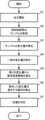
- the operation of the breakage determination device 100 will be described with reference to FIG.
- the numerical control device is started, the setup is completed, and machining is started (step S1).
- the numerical control device moves the axis at rapid traverse and rotates the main spindle at the cutting start position.
- the data acquisition unit 10 acquires the spindle load value as a sample.
- the determination unit 11 determines whether the sample acquired by the data acquisition unit 10 is a sample detected during a cutting time period or a sample detected during a non-cutting time period.
- the data acquisition unit 10 acquires the sample during the cutting time period (step S2).
- the change amount calculation unit 12 calculates the change amount of the samples during the cutting time period (step S3).
- the probability calculation unit 13 excludes some of the change amounts (step S4). Only one sample may be excluded, or multiple samples may be excluded. Values with large changes are excluded, regardless of whether they are positive or negative.
- the probability calculation unit 13 calculates a probability density function from the remaining amount of change after excluding a portion (step S5).
- the probability calculation unit 13 calculates the probability that the amount of change excluded occurs in the calculated probability density function (step S6).
- the probability calculation unit 13 determines that the tool is broken (step S7).
- the breakage detection device 100 of this embodiment obtains the current load value as a sample and uses the obtained value to determine breakage, eliminating the need for test processing and making breakage detection more efficient.
- the modified breakage detection device 100 combines two types of detection methods.
- the breakage detection device 100 in Fig. 9 is obtained by adding a second probability calculation unit 15, a feature amount calculation unit 16, and a second breakage detection unit 17 to the breakage detection device 100 in Fig. 1.
- the second probability calculation unit 15 calculates a probability density function of samples acquired during the non-cutting time period.
- the feature calculation unit 16 obtains feature values of samples acquired during the cutting time period.
- the feature values are representative values of samples acquired during the cutting time period.
- the feature values include the average value, median value, maximum value, minimum value, and mode value.
- the feature values may also be a moving average, moving median value, moving maximum value, moving minimum value, and moving mode value.
- the type of feature value is not limited.
- the second breakage detection unit 17 compares the probability density function of the samples during the non-cutting time period with the feature values of the samples during the cutting time period.
- the second breakage detection unit 17 detects tool breakage if the probability of occurrence of the feature values during the cutting time period is sufficiently small in the probability density function of the samples during the non-cutting time period.
- the breakage detection unit 14 determines breakage from the gradient of the change in the sample.
- the second breakage detection unit 17 determines breakage based on whether or not the characteristic value (representative value) of the sample during the cutting time period occurs during the non-cutting time period.
- the modified breakage detection device 100 determines breakage by combining these two methods.
- breakage can be determined using both the slope and the sample value, which broadens the scope of breakage determination.
- breakage can be detected under a variety of circumstances.
- FIG. 10 is a hardware configuration diagram of the breakage determination device 100.
- the breakage determination device 100 includes a CPU 111 that controls the entire breakage determination device 100, a ROM 112 that records programs and data, and a RAM 113 for temporarily expanding data.
- the CPU 111 reads out a system program recorded in the ROM 112 via a bus and determines whether or not a breakage has occurred according to the system program.
- the non-volatile memory 114 is backed up by, for example, a battery (not shown), and the stored state is maintained even when the power to the breakage determination device 100 is turned off.
- the non-volatile memory 114 stores various data, such as programs read from the external device 120 via the interfaces 115, 118, and 119, and operation inputs input via the input unit 30.
- the non-volatile memory 114 may store programs and data for executing the breakage determination device 100 of this embodiment.
- the interface 115 is an interface for connecting the breakage determination device 100 to an external device 120 such as an adapter. Programs, various parameters, and the like are read from the external device 120.
- the interface 118 is an interface for connecting the breakage determination device 100 to a display unit 70 such as a liquid crystal display. The display unit 70 displays various data loaded onto the memory, data obtained as a result of executing a program, and the like.
- the interface 119 is an interface for connecting the breakage determination device 100 to an input unit 30 such as a keyboard, a pointing device, etc. The input unit 30 passes instructions, data, etc. based on operations by an operator to the CPU 111 via the interface 119.
- the breakage determination device (100) comprises a data acquisition unit (10) that acquires the value of the load applied to the axis of a machine tool as a sample, a determination unit (11) that determines whether the sample acquired by the data acquisition unit (10) is a sample detected during a cutting time period or a sample detected during a non-cutting time period, a change amount calculation unit (12) that calculates an amount of change in the sample during the cutting time period, a probability calculation unit (13) that excludes one or more of the change amounts and calculates a probability density function from the remaining change amounts, and a breakage detection unit (14) that determines tool breakage based on the probability of occurrence of the change amount excluded in the probability density function.
- the determination unit (11) determines cutting time periods and non-cutting time periods based on command signals that control the machine tool.
- the breakage detection unit (14) determines that the tool is broken when the probability of occurrence of the excluded variation is sufficiently small.
- the probability calculation section (13) excludes amounts of change with large absolute values.
- the tool includes a second probability calculation unit (15) that calculates a probability density function of samples in the non-cutting time period, a feature calculation unit (16) that calculates a feature of samples in the cutting time period, and a second breakage detection unit (17) that determines tool breakage based on the probability of occurrence of the feature in the probability density function of the non-cutting time period.
- a computer-readable storage medium (112, 113, 114) stores instructions for causing one or more processors (111) to execute a process of acquiring a value of the load applied to the axis of a machine tool as a sample, determining whether the sample is a sample detected during a cutting time period or a sample detected during a non-cutting time period, calculating an amount of change in the sample during the cutting time period, excluding one or more of the amounts of change, calculating a probability density function from the remaining amounts of change, and determining whether a tool has broken based on the probability of occurrence of the amount of change excluded in the probability density function.
- Breakage determination device 10 Data acquisition unit 11 Determination unit 12 Change amount calculation unit 13 Probability calculation unit 14 Breakage detection unit 111 CPU 112 ROM 113 RAM 114 Non-volatile memory
Landscapes
- Engineering & Computer Science (AREA)
- Mechanical Engineering (AREA)
- Human Computer Interaction (AREA)
- Manufacturing & Machinery (AREA)
- Physics & Mathematics (AREA)
- General Physics & Mathematics (AREA)
- Automation & Control Theory (AREA)
- Numerical Control (AREA)
Abstract
折損判定装置は、工作機械の軸にかかる負荷の値をサンプルとして取得し、サンプルが、切削時間帯に検出されたサンプルであるか、非切削時間帯に検出されたサンプルであるかを判定し、切削時間帯のサンプルの変化量を算出し、変化量の1つ又は複数を除外し、残った変化量から確率密度関数を算出し、確率密度関数において除外した変化量が発生する確率を基に工具の折損を判定する。
Description
本開示は、折損判定装置、及びコンピュータが読み取り可能な記憶媒体に関する。
従来、工作機械で使用される工具の折損を検出あるいは折損を予知する装置において、切削時間帯の負荷の特徴量に係数を乗じて、変動するしきい値を算出し、折損を判定する技術が存在する。例えば、特許文献1。
特許文献1の技術では、試し加工が必要になるため、最初の加工から折損を判定できない。
数値制御装置の分野では、折損の判定を効率化することが望まれている。
折損判定装置は、工作機械の軸にかかる負荷の値をサンプルとして取得するデータ取得部と、データ取得部が取得したサンプルが、切削時間帯に検出されたサンプルであるか、非切削時間帯に検出されたサンプルであるかを判定する判定部と、切削時間帯のサンプルの変化量を算出する変化量算出部と、変化量の1つ又は複数を除外し、残った変化量から確率密度関数を算出する確率算出部と、確率密度関数において除外した変化量が発生する確率を基に工具の折損を判定する折損検出部と、を備える。
以下、折損判定装置について説明する。折損判定装置は、数値制御装置、PC(パーソナルコンピュータ)などの情報処理装置で実現する。
図1は、折損判定装置100のブロック図である。折損判定装置100は、データ取得部10、判定部11、変化量算出部12、確率算出部13、折損検出部14を備える。
データ取得部10は、主軸または送り軸の負荷の少なくとも一方を取得する。以下、負荷の値をサンプルとよぶ。
判定部11は、データ取得部10が取得したサンプルが、切削時間帯に検出されたサンプルであるか非切削時間帯に検出されたサンプルであるかを判定する。切削時間帯とは、工具がワークを切削している時間である。非切削時間帯は、工具がワークを切削していない時間である。
判定方法としては、信号を検出する方法がある。例えば、切削時間帯には数値制御装置から「切削中」指令の信号が出力されている。図2に「切削中」指令の信号の例を示す。図2の上のグラフは負荷の値を示し、図2の下のグラフは「切削中」指令の信号を示す。数値制御装置が加工プログラムなどを解析し、G01などの切削指令を実行するとき、「切削中」指令の信号が「ON」になる。この信号により切削時間帯か非切削時間帯か判定することができる。
判定部11は、データ取得部10が取得したサンプルが、切削時間帯に検出されたサンプルであるか非切削時間帯に検出されたサンプルであるかを判定する。切削時間帯とは、工具がワークを切削している時間である。非切削時間帯は、工具がワークを切削していない時間である。
判定方法としては、信号を検出する方法がある。例えば、切削時間帯には数値制御装置から「切削中」指令の信号が出力されている。図2に「切削中」指令の信号の例を示す。図2の上のグラフは負荷の値を示し、図2の下のグラフは「切削中」指令の信号を示す。数値制御装置が加工プログラムなどを解析し、G01などの切削指令を実行するとき、「切削中」指令の信号が「ON」になる。この信号により切削時間帯か非切削時間帯か判定することができる。
変化量算出部12は、切削時間帯に取得したサンプルの変化量を算出する。サンプルの変化量とは、サンプルの増減値である。変化量算出部12は、ある時点のサンプルの値から、それ以前又は以降のサンプルの値を引いた、サンプルの差分を算出する。
図3は正常時(工具が折損していない時)のサンプルの変化を示すグラフである。正常時において、切削時間帯のサンプルの値は略一定である。サンプルの変化量も大きく変位しない。
図3は正常時(工具が折損していない時)のサンプルの変化を示すグラフである。正常時において、切削時間帯のサンプルの値は略一定である。サンプルの変化量も大きく変位しない。
図4は、切削中に工具が折損したときのサンプルの変化を示す。図4では、説明のため少数(5点)のサンプルを表示する。実際のサンプル数は十分に多いものとする。変化量算出部12は、サンプルの変化量を算出する。サンプル1からサンプル2の変化量は「0」、サンプル2からサンプル3の変化量は「+0.2」、サンプル3からサンプル4の変化量は「-1.5」、サンプル4からサンプル5の変化量は「-0.1」である。変化量算出部12は、十分な数の変化量を算出する。
確率算出部13は、変化量の確率密度関数を算出する。確率算出部13は、前処理を実行する。前処理では、変化量の一部をサンプルから除外する。確率算出部13は、絶対値の大きな値を除外する。すなわち、正負の関係なく変化の大きい値を除外する。除外する個数は、1つでもよいし複数でもよい。除外の基準は、変化の大きさの順序でもよいし、閾値を用いてもよい。
折損検出部14は、サンプルの変化量の確率密度関数を用いて、除外した値の発生する確率を求め、除外した値の発生する確率が十分に小さい場合、工具が折損したと判定する。すなわち、一部の変化量を除外し、残った変化量から算出した確率密度関数において、除外した値の発生する確率が十分小さい場合には、工具が折損したと判定する。
図5は、一部の変化量を除外し、残った変化量から算出した確率密度関数と、除外した変化量の発生する確率との関係を示すグラフである。図5において、右側の正規分布が確率密度関数であり、左側の点が除外した変化量である。図5の例では、除外した変化量が発生する確率が限りなく「0」に近いので、工具が折損したと判定する。
折損検出部14は、サンプルの変化量の確率密度関数を用いて、除外した値の発生する確率を求め、除外した値の発生する確率が十分に小さい場合、工具が折損したと判定する。すなわち、一部の変化量を除外し、残った変化量から算出した確率密度関数において、除外した値の発生する確率が十分小さい場合には、工具が折損したと判定する。
図5は、一部の変化量を除外し、残った変化量から算出した確率密度関数と、除外した変化量の発生する確率との関係を示すグラフである。図5において、右側の正規分布が確率密度関数であり、左側の点が除外した変化量である。図5の例では、除外した変化量が発生する確率が限りなく「0」に近いので、工具が折損したと判定する。
図6は、正常時(折損していない時)のサンプルである。サンプル1からサンプル6の値は、略変化していない。具体的には、サンプル1からサンプル2の変化量は「0.036926」、サンプル2からサンプル3の変化量は「0.173767」、サンプル3からサンプル4の変化量は「0.014832」、サンプル4からサンプル5の変化量は「0.046814」、サンプル5からサンプル6の変化量は「0.006226」、サンプル6からサンプル7の変化量は「0.031311」である。
図6には、各変化量を除外したときの「3σ区間」を列記している。サンプル1からサンプル2の変化量を除外したときの「μ-3σ」は「-0.1094」であり、「μ+3σ」は「0.218577」である。サンプル2からサンプル3の変化量を除外したときの「μ-3σ」は「-0.05415」であり、「μ+3σ」は「0.108589」である。サンプル3からサンプル4の変化量を除外したときの「μ-3σ」は「-0.11801」であり、「μ+3σ」は「0.236033」である。サンプル4からサンプル5の変化量を除外したときの「μ-3σ」は「-0.10553」であり、「μ+3σ」は「0.21075」である。サンプル5からサンプル6の変化量を除外したときの「μ-3σ」は「-0.12136」であり、「μ+3σ」は「0.242822」である。サンプル6からサンプル7の変化量を除外したときの「μ-3σ」は「-0.11159」であり、「μ+3σ」は「0.223017」である。
図7は、切削中に工具が折損したときのサンプルである。サンプル1からサンプル6の値は、急激に変化している。具体的には、サンプル1からサンプル2の変化量は「0.032484」、サンプル2からサンプル3の変化量は「0.128205」、サンプル3からサンプル4の変化量は「0.124071」、サンプル4からサンプル5の変化量は「0.197852」、サンプル5からサンプル6の変化量は「3.245687」、サンプル6からサンプル7の変化量は「15.30834」である。
図7には、各変化量を除外したときの「3σ区間」を列記している。サンプル1からサンプル2の変化量を除外したときの「μ-3σ」は「-7.68314」であり、「μ+3σ」は「15.2848」である。サンプル2からサンプル3の変化量を除外したときの「μ-3σ」は「-7.64643」であり、「μ+3σ」は「15.2098」である。サンプル3からサンプル4の変化量を除外したときの「μ-3σ」は「-7.64801」であり、「μ+3σ」は「15.21304」である。サンプル4からサンプル5の変化量を除外したときの「μ-3σ」は「-7.61971」であり、「μ+3σ」は「15.15523」である。サンプル5からサンプル6の変化量を除外したときの「μ-3σ」は「-6.44736」であり、「μ+3σ」は「12.76374」である。サンプル6からサンプル7の変化量を除外したときの「μ-3σ」は「-1.51215」であり、「μ+3σ」は「3.003473」である。
サンプル6からサンプル7の変化量は「3σ区間」を超えている。「3σ区間」の範囲外の変化量が発生する確率は0.03%である。折損検出部14は、折損が発生したと判定する。
図8を参照して折損判定装置100の動作を説明する。
数値制御装置を起動し、段取りを完了し、加工を開始する(ステップS1)。数値制御装置は、早送りで軸を移動して、切削開始位置で、主軸を回転させる。
データ取得部10は、主軸の負荷の値をサンプルとして取得する。判定部11は、データ取得部10が取得したサンプルが、切削時間帯に検出されたサンプルであるか非切削時間帯に検出されたサンプルであるかを判定する。データ取得部10は、切削時間帯のサンプルを取得する(ステップS2)。
数値制御装置を起動し、段取りを完了し、加工を開始する(ステップS1)。数値制御装置は、早送りで軸を移動して、切削開始位置で、主軸を回転させる。
データ取得部10は、主軸の負荷の値をサンプルとして取得する。判定部11は、データ取得部10が取得したサンプルが、切削時間帯に検出されたサンプルであるか非切削時間帯に検出されたサンプルであるかを判定する。データ取得部10は、切削時間帯のサンプルを取得する(ステップS2)。
変化量算出部12は、切削時間帯のサンプルの変化量を算出する(ステップS3)。確率算出部13は、一部の変化量を除外する(ステップS4)。サンプルは1つだけ除外してもよいし、複数除外してもよい。正負の関係なく変化の大きい値を除外する。
確率算出部13は、一部を除外した残りの変化量から確率密度関数を算出する(ステップS5)。確率算出部13は、算出した確率密度関数において、除外した変化量が発生する確率を算出する(ステップS6)。
確率算出部13は、除外した変化量の発生する確率が十分に低いとき、工具が折損したと判定する(ステップS7)。
確率算出部13は、除外した変化量の発生する確率が十分に低いとき、工具が折損したと判定する(ステップS7)。
本実施形態の折損判定装置100は、現在の負荷の値をサンプルとして取得し、取得した値を用いて折損を判定するため、試し加工が不要であり、折損の判定を効率化することができる。
(変形例)
変形例の折損判定装置100は、2種類の判定方法を組み合わせる。図9の折損判定装置100は、図1の折損判定装置100に、第2の確率算出部15、特徴量算出部16、第2の折損検出部17を追加したものである。
第2の確率算出部15は、非切削時間帯に取得したサンプルの確率密度関数を算出する。特徴量算出部16は、切削時間帯に取得したサンプルの特徴量を求める。特徴量は切削時間帯に取得したサンプルの代表値である。特徴量には、平均値、中央値、最大値、最小値、最頻値などがある。また、特徴量は、移動平均、移動中央値、移動最大値、移動最小値、移動最頻値でもよい。特徴量の種類は、限定しない。
変形例の折損判定装置100は、2種類の判定方法を組み合わせる。図9の折損判定装置100は、図1の折損判定装置100に、第2の確率算出部15、特徴量算出部16、第2の折損検出部17を追加したものである。
第2の確率算出部15は、非切削時間帯に取得したサンプルの確率密度関数を算出する。特徴量算出部16は、切削時間帯に取得したサンプルの特徴量を求める。特徴量は切削時間帯に取得したサンプルの代表値である。特徴量には、平均値、中央値、最大値、最小値、最頻値などがある。また、特徴量は、移動平均、移動中央値、移動最大値、移動最小値、移動最頻値でもよい。特徴量の種類は、限定しない。
第2の折損検出部17は、非切削時間帯のサンプルの確率密度関数と、切削時間帯のサンプルの特徴量とを比較する。第2の折損検出部17は、非切削時間帯のサンプルの確率密度関数において、切削時間帯の特徴量の発生する確率が十分小さい場合、工具の折損を検出する。
折損検出部14は、サンプルの変化の傾きから折損を判定する。第2の折損検出部17は、切削時間帯のサンプルの特徴量(代表値)が非切削時間帯に発生するか否かにより折損を判定する。変形例の折損判定装置100は、これらの2つの方法を組み合わせて折損を判定する。
変形例では、傾きと、サンプルの値との両方を用いて折損が判定できるので、折損判定の幅が広がる。また、特徴量を複数用意することにより、様々な状況下での折損を検出することができる。
以下、本開示を適用した折損判定装置100のハードウェア構成について説明する。図10は、折損判定装置100のハードウェア構成図である。折損判定装置100は、図10に示すように、折損判定装置100を全体的に制御するCPU111、プログラムやデータを記録するROM112、一時的にデータを展開するためのRAM113を備え、CPU111はバスを介してROM112に記録されたシステムプログラムを読み出し、システムプログラムに従って折損を判定する。
不揮発性メモリ114は、例えば、図示しないバッテリでバックアップされるなどして、折損判定装置100の電源がオフされても記憶状態が保持される。不揮発性メモリ114には、インタフェース115、118、119を介して外部装置120から読み込まれたプログラムや入力部30を介して入力された操作入力などの各種データが記憶される。不揮発性メモリ114に、本実施形態の折損判定装置100を実行するためのプログラムおよびデータを記憶してもよい。
インタフェース115は、折損判定装置100とアダプタ等の外部装置120と接続するためのインタフェースである。外部装置120側からはプログラムや各種パラメータ等が読み込まれる。
インタフェース118は、折損判定装置100と液晶ディスプレイ等の表示部70とを接続するためのインタフェースである。表示部70には、メモリ上に読み込まれた各データ、プログラム等が実行された結果として得られたデータ等が表示される。
インタフェース119は、折損判定装置100とキーボード、ポインティングデバイス等の入力部30とを接続するためのインタフェースである。入力部30は、オペレータによる操作に基づく指令、データ等を、インタフェース119を介してCPU111に渡す。
インタフェース118は、折損判定装置100と液晶ディスプレイ等の表示部70とを接続するためのインタフェースである。表示部70には、メモリ上に読み込まれた各データ、プログラム等が実行された結果として得られたデータ等が表示される。
インタフェース119は、折損判定装置100とキーボード、ポインティングデバイス等の入力部30とを接続するためのインタフェースである。入力部30は、オペレータによる操作に基づく指令、データ等を、インタフェース119を介してCPU111に渡す。
本開示について詳述したが、本開示は上述した個々の実施形態に限定されるものではない。これらの実施形態は、本開示の要旨を逸脱しない範囲で、又は、請求の範囲に記載された内容とその均等物から導き出される本開示の主旨を逸脱しない範囲で種々の追加、置き換え、変更、部分的削除等が可能である。また、これらの実施形態は、組合せて実施することもできる。例えば、上述した実施形態において、各動作の順序や各処理の順序は、一例として示したものであり、これらに限定されるものではない。
上記実施形態及び変形例に関し、更に以下の付記を開示する。
(付記1)
折損判定装置(100)は、工作機械の軸にかかる負荷の値をサンプルとして取得するデータ取得部(10)と、前記データ取得部(10)が取得したサンプルが、切削時間帯に検出されたサンプルであるか、非切削時間帯に検出されたサンプルであるかを判定する判定部(11)と、前記切削時間帯のサンプルの変化量を算出する変化量算出部(12)と、前記変化量の1つ又は複数を除外し、残った変化量から確率密度関数を算出する確率算出部(13)と、前記確率密度関数において除外した変化量が発生する確率を基に工具の折損を判定する折損検出部(14)と、を備える。
(付記2)
前記判定部(11)は、前記工作機械を制御する指令の信号を基に、切削時間帯と非切削時間帯とを判定する。
(付記3)
前記折損検出部(14)は、除外した変化量の発生する確率が十分に小さい場合には、工具が折損していると判定する。
(付記4)
前記確率算出部(13)は、絶対値が大きい変化量を除外する。
(付記5)
前記非切削時間帯のサンプルの確率密度関数を算出する第2の確率算出部(15)と、前記切削時間帯のサンプルの特徴量を算出する特徴量算出部(16)と、前記非切削時間帯の確率密度関数において前記特徴量の発生する確率を基に、工具の折損を判定する第2の折損検出部(17)と、を備える。
(付記6)
コンピュータが読み取り可能な記憶媒体(112、113、114)は、1つ又は複数のプロセッサ(111)に、工作機械の軸にかかる負荷の値をサンプルとして取得し、前記サンプルが、切削時間帯に検出されたサンプルであるか、非切削時間帯に検出されたサンプルであるかを判定し、前記切削時間帯のサンプルの変化量を算出し、前記変化量の1つ又は複数を除外し、残った変化量から確率密度関数を算出し、前記確率密度関数において除外した変化量が発生する確率を基に工具の折損を判定する処理を実行させる命令を記憶する。
(付記1)
折損判定装置(100)は、工作機械の軸にかかる負荷の値をサンプルとして取得するデータ取得部(10)と、前記データ取得部(10)が取得したサンプルが、切削時間帯に検出されたサンプルであるか、非切削時間帯に検出されたサンプルであるかを判定する判定部(11)と、前記切削時間帯のサンプルの変化量を算出する変化量算出部(12)と、前記変化量の1つ又は複数を除外し、残った変化量から確率密度関数を算出する確率算出部(13)と、前記確率密度関数において除外した変化量が発生する確率を基に工具の折損を判定する折損検出部(14)と、を備える。
(付記2)
前記判定部(11)は、前記工作機械を制御する指令の信号を基に、切削時間帯と非切削時間帯とを判定する。
(付記3)
前記折損検出部(14)は、除外した変化量の発生する確率が十分に小さい場合には、工具が折損していると判定する。
(付記4)
前記確率算出部(13)は、絶対値が大きい変化量を除外する。
(付記5)
前記非切削時間帯のサンプルの確率密度関数を算出する第2の確率算出部(15)と、前記切削時間帯のサンプルの特徴量を算出する特徴量算出部(16)と、前記非切削時間帯の確率密度関数において前記特徴量の発生する確率を基に、工具の折損を判定する第2の折損検出部(17)と、を備える。
(付記6)
コンピュータが読み取り可能な記憶媒体(112、113、114)は、1つ又は複数のプロセッサ(111)に、工作機械の軸にかかる負荷の値をサンプルとして取得し、前記サンプルが、切削時間帯に検出されたサンプルであるか、非切削時間帯に検出されたサンプルであるかを判定し、前記切削時間帯のサンプルの変化量を算出し、前記変化量の1つ又は複数を除外し、残った変化量から確率密度関数を算出し、前記確率密度関数において除外した変化量が発生する確率を基に工具の折損を判定する処理を実行させる命令を記憶する。
100 折損判定装置
10 データ取得部
11 判定部
12 変化量算出部
13 確率算出部
14 折損検出部
111 CPU
112 ROM
113 RAM
114 不揮発性メモリ
10 データ取得部
11 判定部
12 変化量算出部
13 確率算出部
14 折損検出部
111 CPU
112 ROM
113 RAM
114 不揮発性メモリ
Claims (6)
- 工作機械の軸にかかる負荷の値をサンプルとして取得するデータ取得部と、
前記データ取得部が取得したサンプルが、切削時間帯に検出されたサンプルであるか、非切削時間帯に検出されたサンプルであるかを判定する判定部と、
前記切削時間帯のサンプルの変化量を算出する変化量算出部と、
前記変化量の1つ又は複数を除外し、残った変化量から確率密度関数を算出する確率算出部と、
前記確率密度関数において除外した変化量が発生する確率を基に工具の折損を判定する折損検出部と、
を備える折損判定装置。 - 前記判定部は、前記工作機械を制御する指令の信号を基に、切削時間帯と非切削時間帯とを判定する、請求項1記載の折損判定装置。
- 前記折損検出部は、除外した変化量の発生する確率が十分に小さい場合には、工具が折損していると判定する、請求項1記載の折損判定装置。
- 前記確率算出部は、絶対値が大きい変化量を除外する、請求項1記載の折損判定装置。
- 前記非切削時間帯のサンプルの確率密度関数を算出する第2の確率算出部と、
前記切削時間帯のサンプルの特徴量を算出する特徴量算出部と、
前記非切削時間帯の確率密度関数において前記特徴量の発生する確率を基に、工具の折損を判定する第2の折損検出部と、
を備える請求項1記載の折損判定装置。 - 1つ又は複数のプロセッサに、
工作機械の軸にかかる負荷の値をサンプルとして取得し、
前記サンプルが、切削時間帯に検出されたサンプルであるか、非切削時間帯に検出されたサンプルであるかを判定し、
前記切削時間帯のサンプルの変化量を算出し、
前記変化量の1つ又は複数を除外し、残った変化量から確率密度関数を算出し、
前記確率密度関数において除外した変化量が発生する確率を基に工具の折損を判定する
処理を実行させる命令を記憶するコンピュータが読み取り可能な記憶媒体。
Priority Applications (1)
| Application Number | Priority Date | Filing Date | Title |
|---|---|---|---|
| PCT/JP2023/042856 WO2025115161A1 (ja) | 2023-11-30 | 2023-11-30 | 折損判定装置、及びコンピュータが読み取り可能な記憶媒体 |
Applications Claiming Priority (1)
| Application Number | Priority Date | Filing Date | Title |
|---|---|---|---|
| PCT/JP2023/042856 WO2025115161A1 (ja) | 2023-11-30 | 2023-11-30 | 折損判定装置、及びコンピュータが読み取り可能な記憶媒体 |
Publications (2)
| Publication Number | Publication Date |
|---|---|
| WO2025115161A1 true WO2025115161A1 (ja) | 2025-06-05 |
| WO2025115161A9 WO2025115161A9 (ja) | 2026-03-26 |
Family
ID=95896581
Family Applications (1)
| Application Number | Title | Priority Date | Filing Date |
|---|---|---|---|
| PCT/JP2023/042856 Pending WO2025115161A1 (ja) | 2023-11-30 | 2023-11-30 | 折損判定装置、及びコンピュータが読み取り可能な記憶媒体 |
Country Status (1)
| Country | Link |
|---|---|
| WO (1) | WO2025115161A1 (ja) |
Citations (7)
| Publication number | Priority date | Publication date | Assignee | Title |
|---|---|---|---|---|
| JPS60186353A (ja) * | 1984-03-01 | 1985-09-21 | Matsuura Kikai Seisakusho:Kk | 工具の破損予知装置 |
| US5587931A (en) * | 1995-10-20 | 1996-12-24 | Tri-Way Machine Ltd. | Tool condition monitoring system |
| JPH10146740A (ja) * | 1996-11-14 | 1998-06-02 | Brother Ind Ltd | 工具異常検出装置 |
| JPH10235538A (ja) * | 1997-02-25 | 1998-09-08 | Toyota Motor Corp | 回転工具の異常検出方法およびその装置 |
| JP2003340686A (ja) * | 2002-05-22 | 2003-12-02 | Mitsubishi Materials Corp | 工具の異常検知装置および工具の異常検知方法およびプログラムおよび記録媒体 |
| JP2006082154A (ja) * | 2004-09-14 | 2006-03-30 | Fuji Electric Systems Co Ltd | 刃具診断装置と診断方法 |
| JP2023028734A (ja) * | 2021-08-20 | 2023-03-03 | 株式会社Mazin | 推定負荷利用方法および推定負荷利用システム |
-
2023
- 2023-11-30 WO PCT/JP2023/042856 patent/WO2025115161A1/ja active Pending
Patent Citations (7)
| Publication number | Priority date | Publication date | Assignee | Title |
|---|---|---|---|---|
| JPS60186353A (ja) * | 1984-03-01 | 1985-09-21 | Matsuura Kikai Seisakusho:Kk | 工具の破損予知装置 |
| US5587931A (en) * | 1995-10-20 | 1996-12-24 | Tri-Way Machine Ltd. | Tool condition monitoring system |
| JPH10146740A (ja) * | 1996-11-14 | 1998-06-02 | Brother Ind Ltd | 工具異常検出装置 |
| JPH10235538A (ja) * | 1997-02-25 | 1998-09-08 | Toyota Motor Corp | 回転工具の異常検出方法およびその装置 |
| JP2003340686A (ja) * | 2002-05-22 | 2003-12-02 | Mitsubishi Materials Corp | 工具の異常検知装置および工具の異常検知方法およびプログラムおよび記録媒体 |
| JP2006082154A (ja) * | 2004-09-14 | 2006-03-30 | Fuji Electric Systems Co Ltd | 刃具診断装置と診断方法 |
| JP2023028734A (ja) * | 2021-08-20 | 2023-03-03 | 株式会社Mazin | 推定負荷利用方法および推定負荷利用システム |
Also Published As
| Publication number | Publication date |
|---|---|
| WO2025115161A9 (ja) | 2026-03-26 |
Similar Documents
| Publication | Publication Date | Title |
|---|---|---|
| EP3864475B1 (en) | Method and system for monitoring tool wear to estimate rul of tool in machining | |
| US10222782B2 (en) | Parameter-based controller for managing tool life considering change in machining conditions | |
| KR102648425B1 (ko) | 진동 가속도 신호를 활용한 공구 파손감지 영역 자동설정 방법 및 진동 가속도 신호를 활용한 공구 파손감지장치 | |
| CN117193164B (zh) | 一种数控机床的故障监测方法及系统 | |
| US20200249650A1 (en) | Numerical control system | |
| US9904272B2 (en) | Numerical controller capable of reducing machine load | |
| US10528041B2 (en) | Machining time estimation device | |
| US20210141369A1 (en) | Analyzer | |
| CN112643406B (zh) | 检测装置和记录有程序的记录介质 | |
| CN105938352B (zh) | 避免主轴过热的数值控制装置 | |
| US11226613B2 (en) | Anomaly detection device, anomaly detection server and anomaly detection method | |
| US10429818B2 (en) | Numerical control device | |
| US11073817B2 (en) | Cutting condition verification device | |
| WO2025115161A1 (ja) | 折損判定装置、及びコンピュータが読み取り可能な記憶媒体 | |
| JP2019149041A (ja) | 数値制御装置 | |
| CN111185801A (zh) | 数值控制装置 | |
| WO2025115158A1 (ja) | 折損判定装置、及びコンピュータが読み取り可能な記憶媒体 | |
| JP7667292B2 (ja) | 閾値算出装置、及び記憶媒体 | |
| US20190204143A1 (en) | Method and device for monitoring idle machining of processing machine | |
| US20150073582A1 (en) | Numerical controller having program resuming function | |
| Putz et al. | State-based and self-adapting algorithm for condition monitoring | |
| US20220118576A1 (en) | Tool status detection system and method | |
| JP7304956B2 (ja) | 劣化量検出装置、劣化量検出方法および劣化予測システム | |
| US11156983B2 (en) | Noise monitoring device | |
| WO2025027864A9 (ja) | しきい値算出装置、及びコンピュータが読み取り可能な記憶媒体 |
Legal Events
| Date | Code | Title | Description |
|---|---|---|---|
| 121 | Ep: the epo has been informed by wipo that ep was designated in this application |
Ref document number: 23960179 Country of ref document: EP Kind code of ref document: A1 |
|
| ENP | Entry into the national phase |
Ref document number: 2025560465 Country of ref document: JP Kind code of ref document: A |
|
| WWE | Wipo information: entry into national phase |
Ref document number: 2025560465 Country of ref document: JP |