WO2025104986A1 - 錯触力覚発生装置 - Google Patents
錯触力覚発生装置 Download PDFInfo
- Publication number
- WO2025104986A1 WO2025104986A1 PCT/JP2024/028226 JP2024028226W WO2025104986A1 WO 2025104986 A1 WO2025104986 A1 WO 2025104986A1 JP 2024028226 W JP2024028226 W JP 2024028226W WO 2025104986 A1 WO2025104986 A1 WO 2025104986A1
- Authority
- WO
- WIPO (PCT)
- Prior art keywords
- tactile force
- vibration generator
- generating device
- illusionary tactile
- illusionary
- Prior art date
- Legal status (The legal status is an assumption and is not a legal conclusion. Google has not performed a legal analysis and makes no representation as to the accuracy of the status listed.)
- Pending
Links
Images



Classifications
-
- B—PERFORMING OPERATIONS; TRANSPORTING
- B06—GENERATING OR TRANSMITTING MECHANICAL VIBRATIONS IN GENERAL
- B06B—METHODS OR APPARATUS FOR GENERATING OR TRANSMITTING MECHANICAL VIBRATIONS OF INFRASONIC, SONIC, OR ULTRASONIC FREQUENCY, e.g. FOR PERFORMING MECHANICAL WORK IN GENERAL
- B06B1/00—Methods or apparatus for generating mechanical vibrations of infrasonic, sonic, or ultrasonic frequency
- B06B1/02—Methods or apparatus for generating mechanical vibrations of infrasonic, sonic, or ultrasonic frequency making use of electrical energy
- B06B1/04—Methods or apparatus for generating mechanical vibrations of infrasonic, sonic, or ultrasonic frequency making use of electrical energy operating with electromagnetism
-
- G—PHYSICS
- G06—COMPUTING OR CALCULATING; COUNTING
- G06F—ELECTRIC DIGITAL DATA PROCESSING
- G06F3/00—Input arrangements for transferring data to be processed into a form capable of being handled by the computer; Output arrangements for transferring data from processing unit to output unit, e.g. interface arrangements
- G06F3/01—Input arrangements or combined input and output arrangements for interaction between user and computer
Definitions
- the present invention relates to a technology that creates a tactile illusion for the user.
- Patent Document 1 describes a haptic information presentation system.
- the haptic information presentation system of Patent Document 1 includes a housing that is held by the user.
- a vibrator is built into the housing. A part of the vibrator is exposed from the housing.
- the user receives a haptic sensation by touching the vibrating body while holding the housing.
- Patent Document 1 the user must grip the housing that generates the haptic sensation. This limits the user's actions. For example, the user cannot receive the haptic sensation while touching or holding something else in his or her hand.
- the object of the present invention is therefore to provide a device for generating tactile illusionary forces with a simple structure that can provide multiple types of tactile illusionary forces while minimizing restrictions on the user's actions.
- the tactile illusionary force sense generating device of the present invention is a device capable of imparting a first tactile illusionary force sense and a second tactile illusionary force sense that are different from each other.
- the tactile illusionary force sense generating device comprises a first vibration generator, a second vibration generator, a first wearing device, and a second wearing device.
- the first vibration generator generates a first vibration for generating the first tactile illusionary force sense.
- the second vibration generator generates a second vibration for generating the second tactile illusionary force sense.
- the first wearing device is for wearing the first vibration generator on a finger of any one of the user's hands.
- the second wearing device is for wearing the second vibration generator on the finger.
- the first vibration and the second vibration are different vibrations.
- the first wearing device and the second wearing device are positioned at different positions in the direction in which the fingers extend.
- the user can be given multiple types of illusory tactile sensations simply by attaching the first vibration generator and the second vibration generator to the fingers of any one of their hands.
- This invention makes it possible to provide multiple types of illusory tactile sensations with a simple structure while minimizing restrictions on the user's actions.
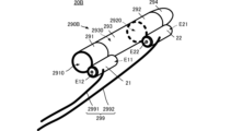
- FIG. 1 is a perspective view showing the appearance of a portion of the illusionary tactile force sense generating device according to the first embodiment that is worn on a hand.
- FIG. 2 is an external perspective view showing the illusionary tactile force sense generating device according to the first embodiment worn on a hand.
- FIG. 3 is a functional block diagram of the illusionary tactile force sense generating device according to the first embodiment.
- Figure 4 (A) shows an image of a tactile force sensation that makes the user feel as if the hand is moving forward (towards the fingertips)
- Figure 4 (B) shows an image of a tactile force sensation that makes the user feel as if the hand is moving backwards (towards the base).
- FIG. 5 shows an image of an illusionary tactile sensation that makes you feel as if you are touching an object with your fingertips.
- FIG. 6 is an external perspective view showing the portion of the illusionary tactile force sense generating device according to the second embodiment that is worn on the hand.
- FIG. 7 is an external perspective view showing a portion of the illusionary tactile force sense generating device according to the third embodiment that is worn on the hand.
- FIG. 8 is a plan view showing the portion of the illusionary tactile force sense generating device according to the fourth embodiment that is worn on the hand.
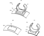
- FIG. 9(A) is an external perspective view showing a derived example of the wearing tool
- FIG. 9(B) is an external perspective view of the main body of the wearing tool
- FIG. 9(C) is an external perspective view of a fixing member of the wearing tool.
- FIG. 1 is a perspective view showing the appearance of a portion of the illusionary tactile force sense generating device according to the first embodiment that is worn on a hand.
- the illusionary tactile sense generating device 20 includes vibration generator 21, vibration generator 22, mounting device 291, mounting device 292, and signal cable 299.
- Signal cable 299 includes signal cable 2991 and signal cable 2992.
- Vibration generator 21 corresponds to the "first vibration generator”
- vibration generator 22 corresponds to the “second vibration generator.”
- Mounting device 291 corresponds to the "first mounting device”
- mounting device 292 corresponds to the "second mounting device.”
- Vibration generator 21 and vibration generator 22 are composed of different types of actuators. Specifically, vibration generator 21 is composed of, for example, an LRA (linear resonant actuator) or a voice coil motor. Vibration generator 22 is composed of, for example, a piezoelectric actuator.
- LRA linear resonant actuator
- Vibration generator 22 is composed of, for example, a piezoelectric actuator.
- the vibration generator 21 is connected to a signal cable 2991. As a result, a first drive signal S1 is supplied to the vibration generator 21 through the signal cable 2991. The vibration generator 21 vibrates due to the first drive signal S1.
- the vibration direction of the vibration generator 21 is parallel to the direction connecting the first end E11 and the second end E12 of the vibration generator 21.
- the vibration by the vibration generator 21 that is parallel to the direction connecting the first end E11 and the second end E12 is referred to as the first vibration.
- the vibration generator 22 is connected to a signal cable 2992. As a result, the second drive signal S2 is supplied to the vibration generator 22 through the signal cable 2992. The vibration generator 22 vibrates due to the second drive signal S2.
- the vibration direction of the vibration generator 22 can be multiple directions, including at least a direction parallel to the direction connecting the first end E21 and the second end E22 of the vibration generator 22.
- the vibration caused by the vibration generator 22 is referred to as the second vibration
- the vibration caused by the vibration generator 22 parallel to the direction connecting the first end E21 and the second end E22 is referred to as the first mode of the second vibration.
- Attachment 291 and attachment 292 are made of a flexible material that can transmit vibrations.
- the attachment 291 is a tubular body (first tubular body) and has a through hole 2910.
- the through hole 2910 is large enough to allow a finger to pass through.
- the attachment 292 is a tubular body (second tubular body) and has a through hole 2920.
- the through hole 2920 is large enough to allow a finger to pass through.
- the vibration generator 21 is fixed to the outer circumferential surface of the mounting fixture 291.
- the axis of the first vibration of the vibration generator 21 is parallel to the extension direction of the tubular body of the mounting fixture 291.
- the vibration generator 22 is fixed to the outer peripheral surface of the mounting fixture 292. At this time, the axis of the first mode of the second vibration of the vibration generator 22 is parallel to the extension direction of the tubular body of the mounting fixture 292.
- mounting fixtures 291 and 292 are not limited to simple tubular bodies, and may be structures formed by deforming a band into a tubular shape.
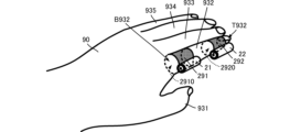
- FIG. 2 is an external perspective view showing a state in which the illusionary tactile force sense generating device according to the first embodiment is worn on a hand.
- Fig. 2 shows the case in which the illusionary tactile force sense generating device is worn on the index finger of the left hand.
- the attachment 291 and the attachment 292 are attached to the index finger 932 of the hand 90.
- the index finger 932 is inserted through the through hole 2910 of the attachment 291 and the through hole 2920 of the attachment 292.
- the inner surfaces of the attachment 291 and the attachment 292 are in close contact with the index finger 932 with a predetermined pressure being applied.
- the surface perpendicular to the direction in which the index finger 932 is inserted into the attachment 291 and the attachment 292 (the opening surface of the through hole 2910 and the through hole 2920) is the attachment surface of the attachment 291 and the attachment 292.
- the attachment 291 is attached between the base B932 and the second joint of the index finger 932.
- the attachment 292 is attached between the tip T932 and the first joint of the index finger 932. That is, the attachment 291 and the attachment 292 are attached in the order of the attachment 291, the attachment 292, along the direction in which the index finger 932 extends, from the base B932 to the tip T932 of the index finger 932.
- the vibration generators 21 and 22 are attached in the order of vibration generator 21, vibration generator 22 along the direction in which the index finger 932 extends, from the base B932 of the index finger 932 to the tip T932.
- the user to whom the illusionary tactile force sense is to be given can wear vibration generator 21 and vibration generator 22 without having to grasp them using the whole hand, etc.
- the illusionary tactile force sense generating device 20 can give the illusionary tactile force sense without reducing the freedom of use of the user's hand.
- the finger on which the illusionary tactile force generating device 20 is worn is not limited to the index finger 932, but may be any of the middle finger 933, ring finger 934, and little finger 935.
- the index finger 932 or little finger 935 is preferable.
- the vibration generator 21 and the vibration generator 22 are preferably placed on the side of the index finger 932 opposite the side of the middle finger 933.
- the illusionary tactile force sense generating device 20 does not necessarily have to be worn on the left hand.
- the illusionary tactile force sense generating device 20 is worn on the left hand when it is desired to give an illusionary tactile force sense to the left hand, and is worn on the right hand when it is desired to give an illusionary tactile force sense to the right hand.
- FIG. 3 is a functional block diagram of the illusionary tactile force sense generating device according to the first embodiment.
- the tactile illusion generating device 20 includes a vibration generator 21, a vibration generator 22, an operation input unit 27, a drive signal generating unit 28, a signal cable 2991, and a signal cable 2992.
- the vibration generator 21 is connected to the drive signal generating unit 28 via a signal cable 2991.
- the vibration generator 22 is connected to the drive signal generating unit 28 via a signal cable 2992.
- the drive signal generating unit 28 is connected to the operation input unit 27.
- the operation input unit 27 accepts a selection input of the type of haptic illusion to be given to the user.
- the operation input unit 27 outputs the type of haptic illusion to the drive signal generation unit 28.
- the drive signal generating unit 28 generates a first drive signal S1 and a second drive signal S2 based on the type of haptic illusion.
- the first drive signal is a signal for imparting a first illusory tactile force.
- the first illusory tactile force is an illusory tactile force that gives the brain the illusion that the hand 90 is moving forward and backward.
- the second drive signal is a signal for imparting a second illusory tactile force.
- the second illusory tactile force is an illusory tactile force that tricks the brain into thinking that an external force is being applied to the finger 932.
- the second illusory tactile force is, for example, an illusory tactile force that is imparted by small vibrations of the part between the fingertip T932 and the first joint.
- the second illusory tactile force is a different type of illusory tactile force from the first illusory tactile force.
- the second illusory tactile force may include an illusory tactile force similar to the first illusory tactile force.
- the first drive signal S1 and the second drive signal S2 are realized by adjusting the waveform, frequency, amplitude, etc. according to the type of illusory tactile sensation.
- the drive signal generating unit 28 supplies the first drive signal S1 to the vibration generator 21 through the signal cable 2991.
- the drive signal generating unit 28 supplies the second drive signal S2 to the vibration generator 22 through the signal cable 2992.
- the vibration generator 21 generates a vibration along the axis of the first vibration (vibration parallel to the direction in which the index finger 932 extends: first vibration) based on the first drive signal S1.
- the first vibration propagates through the attachment 291 to the portion between the base B932 of the index finger 932 and the second joint.
- the tactile illusionary force sense generating device 20 gives the user a first tactile illusionary force sense due to the first vibration applied to the index finger 932.
- the vibration generator 22 generates a vibration (second vibration) along the axis of the second vibration based on the second drive signal S2.
- the second vibration is propagated through the attachment 292 to the portion between the fingertip T932 and the first joint of the index finger 932.
- the illusionary tactile force sense generating device 20 gives a second tactile force sense to the index finger 932 by the second vibration.
- the illusionary tactile force sense generating device 20 can provide the user with a pair of a first illusionary tactile force sense and a second illusionary tactile force sense as shown below.
- First illusionary tactile sensation an illusion of the hand moving
- the vibration generator 21 When the first drive signal S1 is applied to the vibration generator 21, the vibration generator 21 generates a vibration (first vibration) parallel to the direction in which the index finger 932 extends, and applies the vibration to the index finger 932.
- first vibration first vibration
- the illusionary tactile force sense generating device 20 can create an illusion in the brain that the hand is moving forward and backward, as shown in Figures 4(A) and 4(B).
- Figure 4 (A) shows an image of the tactile force illusion that makes you feel as if your hand is moving forward (towards your fingertips), and Figure 4 (B) shows an image of the tactile force illusion that makes you feel as if your hand is moving backward (towards your base).
- the illusory tactile force sensation of the hand moving forward is a illusory tactile force sensation that creates an illusion in the brain that the hand 90 is moving in the direction of the fingertips, even though the hand 90 is not actually moving.
- the illusory tactile force sensation of backward movement of the hand is an illusory tactile force sensation that creates an illusion in the brain that the hand 90 is moving toward the wrist (toward the base of the fingers) even though the hand 90 is not actually moving.
- the vibration generator 22 can also provide the index finger 932 with vibrations similar to those of the vibration generator 21. This allows the illusionary tactile force sense generating device 20 to more effectively create the illusion that the hand is moving forward and backward.
- the vibration generator 22 When the second drive signal S2 is applied to the vibration generator 22, the vibration generator 22 generates vibration and applies it to the index finger 932. As a result, the illusionary tactile force sense generating device 20 can generate an illusion in the brain that makes the fingertip feel as if it is touching some object, as shown in Fig. 5. At this time, the direction of the vibration (second vibration) generated by the vibration generator 22 is not particularly limited, and any vibration may be used.
- Figure 5 shows an image of the haptic illusion that makes you feel as if you are touching an object with your fingertips.
- the illusory tactile sensation that makes the fingertip feel as if it is touching an object is an illusory tactile sensation that creates an illusion in the brain that makes the fingertip T932 or the area around the fingertip T932 feel as if it is touching something, even though the fingertip T932 or the area around the fingertip T932 (specifically, the area between the fingertip T932 and the first joint) is not actually touching anything except the second attachment.
- the tactile illusionary force sense generating device 20 can provide multiple types of tactile illusionary force senses simply by attaching the vibration generator 21 and the vibration generator 22 to one finger 932 of the user. In this way, the tactile illusionary force sense generating device 20 can provide multiple types of tactile illusionary force senses with a simple structure while minimizing restrictions on the user's actions.
- vibration generators 21 and 22 are shorter than the length of the user's finger and are approximately the same as or smaller than the width of the user's finger. This allows the illusionary tactile force sense generating device 20 to suppress any discomfort caused by wearing the illusionary tactile force sense generating device 20.
- FIG. 6 is a perspective view showing the appearance of the part of the illusionary tactile force sense generating device according to the second embodiment that is worn on the hand.
- the illusionary tactile force sense generating device 20A according to the second embodiment differs from the illusionary tactile force sense generating device 20 according to the first embodiment in that it is equipped with a wearing device 290A.
- the other configuration of the illusionary tactile force sense generating device 20A is similar to that of the illusionary tactile force sense generating device 20, and a description of similar parts will be omitted.
- the illusionary tactile force sense generating device 20A includes a mounting device 290A.
- the mounting device 290A includes a mounting device 291, a mounting device 292, and a connection portion 293.
- the mounting device 291 and the mounting device 292 have the configuration shown in the first embodiment.
- connection part 293 is a tubular body and has a through hole 2930.
- the connection part 293 physically connects the mounting fixture 291 and the mounting fixture 292.
- the mounting fixture 291, the connection part 293, and the mounting fixture 292 are connected in this order to form a single cylindrical body.
- connection portion 293 fixes the positional relationship between the mounting fixture 291 and the mounting fixture 292.
- the through hole 2930 of the connection portion 293 communicates with the through hole 2910 of the mounting fixture 291 and the through hole 2920 of the mounting fixture 292.
- attachment 291 and attachment 292 are positioned at predetermined positions on the finger (between the base and the second joint, and between the fingertip and the first joint).
- vibration generator 21 and vibration generator 22 are positioned at predetermined positions on the finger (between the base and the second joint, and between the fingertip and the first joint).
- the tactile illusion generating device 20A can provide multiple types of tactile illusions with a simple structure while minimizing restrictions on the user's actions, and can provide multiple types of tactile illusions with greater reliability through easy attachment.
- a mounting mark MK may be formed near one end of the extension direction of the mounting device 290A (for example, the part overlapping the mounting device 291). This prevents the user from mounting the illusionary tactile force sense generating device 20A in the wrong direction.
- the position and shape of the mounting mark MK are not limited to the example in FIG. 6, and may be other as long as the user can tell the direction in which to mount the illusionary tactile force sense generating device 20A.
- connection part 293 of the attachment 290 can be made of a different material than the attachments 291 and 292.
- the attachments 291 and 292 can transmit vibrations more easily than the connection part 293, and the connection part 293 can be made to have better wearability than the attachments 291 and 292.
- the attachment devices 291 and 292 have a certain thickness and are structured to fit closely to the finger, and the connection portion 293 is structured to stretch easily in the circumferential direction of the cylinder, but not easily in the axial direction of the cylinder. This makes it easy to attach the attachment devices 291 and 292 by the connection portion 293, while efficiently transmitting vibrations from the attachment devices 291 and 292 to the finger, and also makes the positional relationship between the attachment devices 291 and 292 more stable.
- Fig. 7 is a perspective view showing the appearance of the part of the illusionary tactile force sense generating device according to the third embodiment that is worn on the hand.
- the illusionary tactile force sense generating device 20B according to the third embodiment differs from the illusionary tactile force sense generating device 20A according to the second embodiment in that it is equipped with a wearing device 290B.
- the other configuration of the illusionary tactile force sense generating device 20B is the same as that of the illusionary tactile force sense generating device 20A, and a description of similar parts will be omitted.
- attachment device 290B differs from attachment device 290A in that it includes a tip portion 294. Specifically, tip portion 294 is connected to the end opposite the end that connects to connection portion 293 in attachment device 292. Tip portion 294 is bag-shaped with a closed end opposite the end that connects to attachment device 292.
- the attachment 290B has a deep bag shape.
- attachment 291 and attachment 292 are positioned at predetermined positions on the finger (between the base and the second joint, and between the fingertip and the first joint).
- vibration generator 21 and vibration generator 22 are positioned at predetermined positions on the finger (between the base and the second joint, and between the fingertip and the first joint).
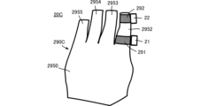
- FIG. 8 is a plan view showing a portion of the illusionary tactile force sense generating device according to the fourth embodiment that is worn on the hand.
- the illusionary tactile force sense generating device 20C according to the fourth embodiment differs from the illusionary tactile force sense generating device 20 according to the first embodiment in that it includes a wearing device 290C.
- the other configuration of the illusionary tactile force sense generating device 20C is similar to that of the illusionary tactile force sense generating device 20, and a description of similar parts will be omitted.
- the wearing device 290C is glove-shaped.
- the wearing device 290C has a main body 2950 that covers the back and palm of the hand, and multiple finger insertion sections 2952, 2953, 2954, and 2955.
- the attachment 291 is positioned near the end of the finger insertion section 2952 that connects to the main body part 2950.
- one end of the attachment 291 (the end opposite the attachment 292 side) is at approximately the same position as the end of the finger insertion section 2952 that connects to the main body part 2950.
- the attachment 292 is positioned near the tip end of the finger insertion section 2952 that is opposite the end of the finger insertion section 2952 that connects to the main body part 2950.
- one end of the attachment 292 (the end opposite the attachment 291 side) is at approximately the same position as the tip end of the finger insertion section 2952.
- attachment 291 and attachment 292 are positioned at predetermined positions on the finger (between the base and the second joint, and between the fingertip and the first joint).
- vibration generator 21 and vibration generator 22 are positioned at predetermined positions on the finger (between the base and the second joint, and between the fingertip and the first joint).
- the tactile illusion generating device 20C can provide multiple types of tactile illusions with a simple structure while minimizing restrictions on the user's actions, and can also provide multiple types of tactile illusions more reliably with easier wearing.
- wearing device 290C is shown to have a shape that covers the entire back of the hand and the palm, it is sufficient that the shape covers at least a portion of the back of the hand and at least a portion of the palm. Also, the finger insertion portion where wearing device 291 and wearing device 292 are not placed can be omitted.
- a flexible mounting fixture is used as an example.
- a mounting fixture having the following structure may also be used.
- Figure 9(A) is an external perspective view showing an example of a derived attachment
- Figure 9(B) is an external perspective view of the main body of the attachment
- Figure 9(C) is an external perspective view of the fixing member of the attachment.
- the derived example attachment 291D can be substituted for attachment 291 and attachment 292 described above.
- the mounting fixture 291D comprises a main body 2911 and a fixing member 31.
- the main body 2911 corresponds to the "first main body” and the "second main body”
- the fixing member 31 corresponds to the "first fixing member” and the "second fixing member”.
- the main body 2911 is a band-shaped or tubular body.
- the main body 2911 is preferably flexible and stretchable.
- the main body 2911 has a through hole TH.
- the fixed member 31 is made of a material that is harder than the main body 2911 and that easily transmits vibrations.
- the fixed member 31 includes a gripping member 311, a base member 312, and a stand 313.
- the gripping member 311, the base member 312, and the stand 313 are, for example, integrally formed.
- the gripping member 311 is an annular body with a portion of the peripheral wall missing.
- the vibration generator 21 and the vibration generator 22 are attached to the gripping member 311.
- the base member 312 has a curved shape that corresponds to the shape of the finger.
- the gripping member 311 is fixed to the base member 312 using a base 313.
- the fixing member 31 is placed on the main body 2911 with the base 313 inserted through the through hole TH.
- the attachment 291D is fixed with the base 313 of the fixing member 31 in contact with the surface of the finger. Since the base 313 is made of a material that easily transmits vibrations, the vibrations generated by the vibration generator 21 (vibration generator 22) are effectively transmitted to the user's finger.
- the illusionary tactile sense generating device equipped with the attachment 291D can more effectively impart an illusionary tactile sense to the user.
- the mounting device 291D has a through hole TH in the main body 2911.
- the base 313 comes into contact with the finger via the bottom of the bag, but having a bottom reduces damage to the finger compared to when the base 313 comes into direct contact with the finger, and making the bottom thin reduces the reduction in the effectiveness of providing the user with an illusionary tactile sensation.
- An illusionary tactile force sense generating device capable of imparting a first illusionary tactile force sense and a second illusionary tactile force sense that are different from each other, A first vibration generator that generates a first vibration for generating the first illusionary tactile force; A second vibration generator that generates a second vibration for generating the second illusionary tactile force; a first wearing tool for wearing the first vibration generator on a finger of any one hand of a user; a second attachment for attaching the second vibration generator to the finger; Equipped with The first vibration and the second vibration are different vibrations, An illusionary tactile sense generating device, wherein the first wearing device and the second wearing device are positioned at different positions in the direction in which the finger extends.
- the first wearing tool is a first tubular body having flexibility
- any of the illusionary tactile sense generating devices ⁇ 1> to ⁇ 3> comprising a connection part that connects the first wearing device and the second wearing device and fixes the positional relationship between the first wearing device and the second wearing device.
- ⁇ 5> The illusionary tactile sensation generating device of ⁇ 4>, in which the first wearing device, the second wearing device, and the connection part are formed from a single cylindrical body.
- the first illusionary tactile force sense is an illusionary tactile force sense that creates an illusion that the hand has moved
- the second illusionary tactile force is an illusionary tactile force that creates the illusion that an external force is applied to a specific position of the finger.
- An illusionary tactile sensation generating device according to any one of ⁇ 4> to ⁇ 6>, comprising the first wearing device, the second wearing device, and the connecting portion, and a glove covering at least a portion of at least one of the back of the hand or the palm.
- the first wearing tool is A first main body having flexibility; a first fixing member disposed on the first main body and to which the first vibration generator is fixed; Equipped with The first fixing member is harder than the first main body.
- the second wearing tool is A second main body having flexibility; a second fixing member disposed on the second main body and to which the second vibration generator is fixed; Equipped with The second fixing member is harder than the second main body.
Landscapes
- Engineering & Computer Science (AREA)
- Physics & Mathematics (AREA)
- General Engineering & Computer Science (AREA)
- Theoretical Computer Science (AREA)
- Electromagnetism (AREA)
- Mechanical Engineering (AREA)
- Human Computer Interaction (AREA)
- General Physics & Mathematics (AREA)
- User Interface Of Digital Computer (AREA)
Priority Applications (2)
| Application Number | Priority Date | Filing Date | Title |
|---|---|---|---|
| CN202480061443.3A CN121925620A (zh) | 2023-11-14 | 2024-08-07 | 错触觉力感产生装置 |
| JP2025557653A JPWO2025104986A1 (https=) | 2023-11-14 | 2024-08-07 |
Applications Claiming Priority (2)
| Application Number | Priority Date | Filing Date | Title |
|---|---|---|---|
| JP2023193540 | 2023-11-14 | ||
| JP2023-193540 | 2023-11-14 |
Publications (1)
| Publication Number | Publication Date |
|---|---|
| WO2025104986A1 true WO2025104986A1 (ja) | 2025-05-22 |
Family
ID=95742851
Family Applications (1)
| Application Number | Title | Priority Date | Filing Date |
|---|---|---|---|
| PCT/JP2024/028226 Pending WO2025104986A1 (ja) | 2023-11-14 | 2024-08-07 | 錯触力覚発生装置 |
Country Status (3)
| Country | Link |
|---|---|
| JP (1) | JPWO2025104986A1 (https=) |
| CN (1) | CN121925620A (https=) |
| WO (1) | WO2025104986A1 (https=) |
Citations (5)
| Publication number | Priority date | Publication date | Assignee | Title |
|---|---|---|---|---|
| JP2000501033A (ja) * | 1995-11-30 | 2000-02-02 | ヴァーチャル テクノロジーズ インコーポレイテッド | 触覚をフィードバックする人間/機械インターフェース |
| WO2009151121A1 (ja) * | 2008-06-13 | 2009-12-17 | 学校法人 早稲田大学 | 感覚呈示システム及び感覚呈示装置 |
| WO2018092595A1 (ja) * | 2016-11-17 | 2018-05-24 | ソニー株式会社 | 振動提示装置および振動提示方法、並びにプログラム |
| US10082875B1 (en) * | 2017-06-05 | 2018-09-25 | Korea Institute Of Science And Technology | Vibrating apparatus, system and method for generating tactile stimulation |
| JP2021149890A (ja) * | 2020-03-24 | 2021-09-27 | 株式会社エヌアンドエヌ | 情報伝達装置及び情報伝達システム |
-
2024
- 2024-08-07 JP JP2025557653A patent/JPWO2025104986A1/ja active Pending
- 2024-08-07 CN CN202480061443.3A patent/CN121925620A/zh active Pending
- 2024-08-07 WO PCT/JP2024/028226 patent/WO2025104986A1/ja active Pending
Patent Citations (5)
| Publication number | Priority date | Publication date | Assignee | Title |
|---|---|---|---|---|
| JP2000501033A (ja) * | 1995-11-30 | 2000-02-02 | ヴァーチャル テクノロジーズ インコーポレイテッド | 触覚をフィードバックする人間/機械インターフェース |
| WO2009151121A1 (ja) * | 2008-06-13 | 2009-12-17 | 学校法人 早稲田大学 | 感覚呈示システム及び感覚呈示装置 |
| WO2018092595A1 (ja) * | 2016-11-17 | 2018-05-24 | ソニー株式会社 | 振動提示装置および振動提示方法、並びにプログラム |
| US10082875B1 (en) * | 2017-06-05 | 2018-09-25 | Korea Institute Of Science And Technology | Vibrating apparatus, system and method for generating tactile stimulation |
| JP2021149890A (ja) * | 2020-03-24 | 2021-09-27 | 株式会社エヌアンドエヌ | 情報伝達装置及び情報伝達システム |
Also Published As
| Publication number | Publication date |
|---|---|
| CN121925620A (zh) | 2026-04-24 |
| JPWO2025104986A1 (https=) | 2025-05-22 |
Similar Documents
| Publication | Publication Date | Title |
|---|---|---|
| US20180335842A1 (en) | Haptic feedback glove | |
| US20180335841A1 (en) | Haptic feedback glove | |
| EP0981423B1 (en) | Force-feedback interface device for the hand | |
| WO2005032771A1 (ja) | ロボットハンド | |
| KR20150114899A (ko) | 연성 장착 햅틱 출력 디바이스를 갖는 웨어러블 디바이스 | |
| JP2004213350A (ja) | 力覚提示装置及び画像補正方法 | |
| KR20200110502A (ko) | 햅틱 컨트롤러 및 이를 이용한 햅틱 피드백 제공 시스템 및 방법 | |
| EP3043739B1 (en) | Ultrasonic dental scaler insert with ergonomic grip | |
| JP7366117B2 (ja) | 触覚リング | |
| JP2014180298A (ja) | 指アシスト装置 | |
| WO2025104986A1 (ja) | 錯触力覚発生装置 | |
| WO2018212971A1 (en) | Haptic feedback glove | |
| JP2009113184A (ja) | 受動的力覚フィードバック装置および受動的力覚フィードバックシステム | |
| JP3132327U (ja) | 指圧マッサージ手袋 | |
| JP4724109B2 (ja) | ロボットの外被 | |
| EP1974710A1 (en) | Finger pressing massage glove | |
| KR20100089018A (ko) | 진동촉각장치 및 이를 이용한 진동 방법 | |
| WO2024177095A1 (ja) | 錯触力覚発生装置 | |
| JP7616217B2 (ja) | 触覚提示装置 | |
| JP2017004240A (ja) | 方向提示装置 | |
| CN111566598B (zh) | 可穿戴装置和安装夹具 | |
| JP6432140B2 (ja) | 指関節駆動装置 | |
| JPWO2024177095A5 (https=) | ||
| JP7747598B2 (ja) | 触覚デバイス | |
| JPWO2025104986A5 (https=) |
Legal Events
| Date | Code | Title | Description |
|---|---|---|---|
| 121 | Ep: the epo has been informed by wipo that ep was designated in this application |
Ref document number: 24891030 Country of ref document: EP Kind code of ref document: A1 |
|
| ENP | Entry into the national phase |
Ref document number: 2025557653 Country of ref document: JP Kind code of ref document: A |
|
| WWE | Wipo information: entry into national phase |
Ref document number: 2025557653 Country of ref document: JP |