WO2025104818A1 - プログラム、プログラマブル表示器、設定装置及び設定方法 - Google Patents
プログラム、プログラマブル表示器、設定装置及び設定方法 Download PDFInfo
- Publication number
- WO2025104818A1 WO2025104818A1 PCT/JP2023/040971 JP2023040971W WO2025104818A1 WO 2025104818 A1 WO2025104818 A1 WO 2025104818A1 JP 2023040971 W JP2023040971 W JP 2023040971W WO 2025104818 A1 WO2025104818 A1 WO 2025104818A1
- Authority
- WO
- WIPO (PCT)
- Prior art keywords
- control
- programmable display
- setting
- screen
- unit
- Prior art date
- Legal status (The legal status is an assumption and is not a legal conclusion. Google has not performed a legal analysis and makes no representation as to the accuracy of the status listed.)
- Pending
Links
Images






Classifications
-
- G—PHYSICS
- G06—COMPUTING OR CALCULATING; COUNTING
- G06F—ELECTRIC DIGITAL DATA PROCESSING
- G06F3/00—Input arrangements for transferring data to be processed into a form capable of being handled by the computer; Output arrangements for transferring data from processing unit to output unit, e.g. interface arrangements
- G06F3/01—Input arrangements or combined input and output arrangements for interaction between user and computer
- G06F3/048—Interaction techniques based on graphical user interfaces [GUI]
- G06F3/0481—Interaction techniques based on graphical user interfaces [GUI] based on specific properties of the displayed interaction object or a metaphor-based environment, e.g. interaction with desktop elements like windows or icons, or assisted by a cursor's changing behaviour or appearance
-
- G—PHYSICS
- G06—COMPUTING OR CALCULATING; COUNTING
- G06F—ELECTRIC DIGITAL DATA PROCESSING
- G06F3/00—Input arrangements for transferring data to be processed into a form capable of being handled by the computer; Output arrangements for transferring data from processing unit to output unit, e.g. interface arrangements
- G06F3/16—Sound input; Sound output
Definitions
- This disclosure relates to a program, a programmable display, a setting device, and a setting method.
- programmable displays In production sites, programmable displays are used to monitor and control equipment. Programmable displays display objects for displaying information about the equipment, objects for controlling the equipment, and so on on a control screen.
- the control screen of a programmable display can be designed by the user, so the control screen can be customized to suit the production site.
- Patent Document 1 discloses a programmable display that allows the user to easily specify the control target by speech by setting a search keyword and a formula for converting the search keyword into a numerical value. This technology therefore reduces the effort required of the user to access objects that are hidden.
- Patent Document 1 requires the user to set up a large number of search keywords and calculation formulas in advance when configuring the programmable display, which places a heavy burden on the user when configuring the device.
- the purpose of the present disclosure is to provide a program, a programmable display, a setting device, and a setting method that can reduce the effort required to access objects when using a programmable display without placing a significant burden on the user when setting up the programmable display.
- the program according to the present disclosure comprises: Computer, A display control means for displaying on a display device a design screen for designing a control screen for the programmable display device; an object generating means for generating an object to be set on the control screen of the programmable display device based on an input by a user on the design screen; a labeling means for automatically generating a control keyword based on the content of the object and for assigning a label including the control keyword to the object; a setting means for setting the object and the label assigned to the object on the programmable display; Function as.
- FIG. 1 is a diagram showing an overall configuration of a control system according to an embodiment of the present disclosure.
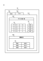
- FIG. 1 is a diagram illustrating an example of a control screen of a programmable display according to an embodiment of the present disclosure.
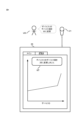
- FIG. 1 is a diagram illustrating an example of a control screen of a programmable display according to an embodiment of the present disclosure.
- FIG. 1 is a diagram illustrating an example of voice recognition by a programmable display device according to an embodiment of the present disclosure.
- FIG. 1 is a diagram illustrating an example of image recognition by a programmable display according to an embodiment of the present disclosure.
- FIG. 1 is a diagram showing a functional configuration of a setting device according to an embodiment of the present disclosure.
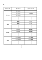
- FIG. 13 is a diagram illustrating an example of a control keyword that is automatically generated by a label assignment unit of a setting device according to an embodiment of the present disclosure.
- FIG. 13 is a diagram showing an example of a control keyword added by a label adding unit of a setting device according to an embodiment of the present disclosure, in response to a user's specification.
- FIG. 1 is a diagram showing a functional configuration of a programmable display device according to an embodiment of the present disclosure.
- FIG. 1 is a diagram illustrating an example of a hardware configuration of a setting device and a programmable display device according to an embodiment of the present disclosure.
- 1 is a flowchart showing an example of an operation for setting a programmable display device by a setting device according to an embodiment of the present disclosure.
- 1 is a flowchart showing an example of a voice recognition operation performed by a programmable display device according to an embodiment of the present disclosure.
- the control system 1 includes a setting device 10, a programmable display 20, a microphone 21, a camera 22, and one or more devices 30.
- the setting device 10 and the programmable display 20 are communicatively connected.
- the programmable display 20, the microphone 21, and the camera 22 are communicatively connected.
- the programmable display 20 and the devices 30 are communicatively connected.
- the programmable display 20, microphone 21, camera 22, and device 30 are provided at the production site.
- the setting device 10 may be provided at the production site, or at a location different from the production site. As described below, the setting device 10 is used when setting the programmable display 20, and therefore the setting device 10 may be connected to the programmable display 20 only when setting the programmable display 20.
- the setting device 10 sets the programmable display 20.
- the setting device 10 is used in particular for designing a control screen to be displayed on the programmable display 20.
- the setting device 10 is, for example, a computer such as a personal computer or tablet terminal on which an engineering tool program is installed.
- the setting device 10 is an example of a setting device according to the present disclosure.
- the programmable display 20 has a touch screen that can be touched and displays a control screen on the touch screen.
- a user can operate the programmable display 20 on the control screen by touching the touch screen of the programmable display 20.
- a user can also operate the programmable display 20 by voice recognition based on voice input to the microphone 21 and image recognition based on images captured by the camera 22.
- the programmable display 20 is an example of a programmable display according to the present disclosure.
- the control screen displayed on the programmable display 20 includes objects that display information about the device 30, objects for controlling the device 30, and the like.
- the control screen is, for example, as shown in Figures 2 and 3.
- the main screen SC1 includes an object OB1 that displays a list of device values, and an object OB2 that indicates the operating status of the equipment 30.
- the user can check the device values of each device in the device display field DV included in the object OB1.
- the user can also change the device value by touching the change button BT included in the object OB1.
- the user can check the operating status of each equipment 30 in the equipment display field AP included in the object OB2.
- the tab TB1, the main screen SC1, the tab TB2 described below, the graph screen SC2 described below, the object OB1, the device display field DV, the change button BT, the object OB2, the equipment display field AP, and the graph G described below are all objects.
- FIG. 3 shows a control screen including a graph screen SC2 on which a graph G showing changes in the device value of device 3 is displayed, and a tab TB2 for displaying the graph screen SC2 is selected.
- the user cannot change the device value by touching.
- the user In order to change the device value by touching, the user must first touch the tab TB1 to transition to the main screen SC1 shown in FIG. 2, and then touch the change button BT of object OB1.
- the user can change the device value by voice recognition without transitioning to the main screen SC1.
- the programmable display 20 recognizes the voice input to the microphone 21 and changes the device value of device 1, which is a different device from device 3 displayed in graph G, to 20.
- the programmable display 20 displays a notification NT on the control screen to notify the user US that the device value of device 1 has been changed to 20.
- the user can operate the programmable display 20 by voice recognition, regardless of the content displayed on the control screen, and without transitioning to the main screen SC1.
- the device value of device 3 When the device value of device 3 is highly dependent on the device value of device 1, as shown in FIG. 4, the device value of device 3 will change significantly in response to a change in the device value of device 1. Changing the device value through voice recognition does not require screen transitions, so the device value can be changed while graph G is displayed on the control screen. This allows the user US to fully confirm that the device value of device 3 will change significantly in response to a change in the device value of device 1. On the other hand, changing the device value through a touch operation requires transitioning to the main screen SC1, so the user US cannot change the device value while viewing graph G, and therefore cannot fully confirm the change in the device value of device 3.
- the user can change the device value by image recognition without transitioning to the main screen SC1.
- the programmable display device 20 recognizes the image captured by the camera 22 and changes the device value of device 1 to 20.
- the programmable display device 20 displays a notification NT on the control screen to notify the user that the device value of device 1 has been changed to 20.
- the user may capture an image of a smartphone, tablet terminal, etc. on which the character string is drawn.
- the user can also check the device values and operating status by voice or image recognition. For example, as shown in FIG. 3, when the user is displaying the graph screen SC2, the user can say "operating status of sensor 2" and the operating status of sensor 2 will be notified on the control screen.
- voice and image recognition are also possible when the main screen SC1 is displayed. For example, if the user is wearing thick gloves while working at a production site, they will not be able to perform touch operations, but they can use voice or image recognition to change the device value of the device displayed in object OB1 on the main screen SC1.
- the user can also issue commands to switch between displaying and hiding objects using voice recognition or image recognition. For example, as shown in FIG. 2, the user can hide the object OB2 that displays the operating status by saying "Hide operating status" when the main screen SC1 is displayed. The user can also display the object OB2 that displays the operating status by saying "Show operating status" when the object OB2 that displays the operating status is hidden.
- the user of the programmable display device 20 can control the programmable display device 20 through voice recognition and image recognition.
- the control screen of the programmable display device 20 may include, in addition to the above, an object for starting and stopping the device 30, an object for displaying the current time, an object for contacting the manufacturer of the device 30, and the like.
- the control screen may also include tabs other than the tab TB1 for displaying the main screen SC1 and the tab TB2 for displaying the graph screen SC2.
- the setting device 10 includes a communication unit 11, a display unit 12, an input unit 13, a display control unit 101, an object generation unit 102, a label assignment unit 103, and a setting unit 104.
- the communication unit 11 communicates with the programmable display device 20.
- the communication unit 11 transmits information indicating the setting contents to the programmable display device 20 when objects and labels are set by the setting unit 104 described below.
- the display unit 12 displays a design screen that provides a user interface necessary for the user of the setting device 10 to design a control screen for the programmable display device 20, based on the control of the display control unit 101.
- the display unit 12 is, for example, a liquid crystal display. Note that the display unit 12 may be a touch screen integrated with the input unit 13 described below.
- the display unit 12 is an example of a display device according to the present disclosure.
- the input unit 13 accepts input operations by a user of the setting device 10 and outputs a signal corresponding to the input operation.
- the input unit 13 is, for example, a keyboard and a mouse.
- the input unit 13 may be a touch screen integrated with the display unit 12.
- the display control unit 101 causes the display unit 12 to display a design screen for designing a control screen for the programmable display device 20.
- the display control unit 101 causes the display unit 12 to display information about the object and the label.
- the display control unit 101 is an example of a display control means according to the present disclosure.
- the object generating unit 102 generates an object to be set on the control screen of the programmable display device 20 based on an input made by the user to the design screen displayed on the display unit 12 via the input unit 13. Specifically, in response to an operation by the user on the design screen to create an object and place it on the design screen, the object generating unit 102 generates an object corresponding to the user's operation.
- the object generating unit 102 is an example of an object generating means according to the present disclosure.
- tab TB1, main screen SC1, tab TB2, graph screen SC2, object OB1, device display field DV, change button BT, object OB2, equipment display field AP, and graph G are all objects.
- objects do not have to be displayed.
- a user can create a device on the design screen as an object that is not displayed.
- the user can create a device display field DV that displays the name and device value of the device corresponding to the device display field by associating the device, which is an object that was previously created, with the device display field DV.
- the user can also create, for example, the internal functions of the programmable display device 20 as objects that are not displayed.
- the label assignment unit 103 automatically generates a control keyword based on the contents of the object generated by the object generation unit 102, and assigns a label including the generated control keyword to the object.
- the control keyword is a keyword that is required when controlling the programmable display device 20 by specifying an object using the above-mentioned voice recognition, image recognition, etc.
- the label assignment unit 103 assigns a label including the control keyword to the object, allowing the user of the programmable display device 20 to control the programmable display device 20 using voice recognition and image recognition.
- the label assignment unit 103 is an example of a label assignment means according to the present disclosure.
- the label assignment unit 103 automatically generates a character string that combines a name corresponding to the type of object with a consecutive number assigned to each type as a control keyword.
- the character string may be used as the control keyword.
- the label assignment unit 103 may generate the character string "Device Value List” as the control keyword for object OB1.
- the labeling unit 103 automatically generates control keywords based on the contents of the object, and assigns a label including the control keyword to the object. This eliminates the need for the user to manually assign labels to all objects in order to control the programmable display 20 using voice recognition and image recognition. In particular, since there are many devices and equipment, the burden on the user can be significantly reduced by automatically generating control keywords and assigning labels to device and equipment objects.
- the user of the setting device 10 can specify additional control keywords of any kind for the object by operating the design screen.
- the label assignment unit 103 assigns a new label including the new control keyword additionally specified by the user of the setting device 10 to the object. This allows the user of the programmable display device 20 to control the programmable display device 20 based on the new control keyword added by the user of the setting device 10 through voice recognition, image recognition, etc.
- the setting unit 104 sets the object generated by the object generating unit 102 and the label assigned to the object by the label assigning unit 103 in the programmable display 20 via the communication unit 11. Specifically, the object and the label are set in the programmable display 20 by transmitting information indicating the setting contents for the object and the label to the programmable display 20 via the communication unit 11. With this setting, the control screen designed by the user of the setting device 10 is reflected in the programmable display 20, and the user of the programmable display 20 can control the programmable display 20 based on a control keyword by voice recognition and image recognition.
- the setting unit 104 sets the programmable display 20 when, for example, the user performs an operation to execute the setting of the programmable display 20 on the design screen.
- the setting unit 104 is an example of a setting means according to the present disclosure.
- the programmable display device 20 includes a communication unit 200, a setting reception unit 201, a memory unit 202, a display unit 203, a recognition unit 204, and an object execution unit 205.
- the communication unit 200 communicates with the setting device 10 and the device 30.
- the communication unit 200 receives information indicating the setting contents of objects and labels from the setting device 10, and communicates with the device 30 based on the control of the object execution unit 205 described below.
- the setting reception unit 201 receives the setting of objects and labels assigned to the objects by the setting unit 104 of the setting device 10. Specifically, when the communication unit 200 receives information indicating the setting contents transmitted by the setting unit 104 of the setting device 10 via the communication unit 11, the setting reception unit 201 stores the received information indicating the setting contents in the storage unit 202. The setting reception unit 201 sets objects and labels based on the information indicating the setting contents, generates a control screen based on the objects, and displays it on the display unit 203 described below.
- the setting reception unit 201 is an example of a setting reception means related to the present disclosure.
- the storage unit 202 stores information indicating the settings received by the setting reception unit 201. Therefore, the storage unit 202 stores information about objects and information about corresponding labels.
- the display unit 203 displays a screen based on the control of the setting reception unit 201 and the object execution unit 205 described below.
- the display unit 203 displays a control screen such as that shown in FIG. 2 and FIG. 3.
- the display unit 203 is an example of a display means according to the present disclosure.
- the recognition unit 204 recognizes voice input by the microphone 21 and converts it into information indicating a character string.
- the recognition unit 204 recognizes an image captured by the camera 22 and converts it into information indicating a character string.
- the recognition unit 204 outputs the obtained information indicating the character string to the object execution unit 205.
- the recognition unit 204 attempts voice recognition on the assumption that the input voice is a human voice, and outputs the recognition result as a character string.
- the recognition unit 204 attempts image recognition on the captured image on the assumption that the captured image is an image on which a character string is drawn, and outputs the recognition result as a character string. If the character string includes a control keyword, the user has performed an operation based on voice recognition or image recognition targeting the control keyword.
- the object execution unit 205 interprets the information indicating the character string output by the recognition unit 204 based on the control keyword indicated by the object information stored in the storage unit 202 and the label information corresponding to the object, and identifies the control content for the programmable display device 20.
- the object execution unit 205 executes an operation based on the identified control content. In other words, the object execution unit 205 executes an operation based on the labeled object based on an operation targeting the control keyword contained in the label.
- the object execution unit 205 updates the control screen according to the execution result. For example, the object execution unit 205 displays a notification indicating the execution result on the control screen.
- the object execution unit 205 is an example of an object execution means according to the present disclosure.
- control of the object corresponding to the keyword can be performed even when the target object is not displayed on the control screen, so the object execution unit 205 executes an action based on the object regardless of whether the object is displayed on the control screen.
- the setting device 10 is realized by a computer such as a personal computer or a tablet terminal on which an engineering tool program is installed.
- the programmable display 20 is realized by a computer such as a personal computer or a microcontroller.
- the setting device 10 and the programmable display 20 will be collectively referred to as the "setting device 10, etc.”.
- the setting device 10 etc. includes a processor 1001, a memory 1002, an interface 1003, and a secondary storage device 1004, which are connected to each other via a bus 1000.
- the processor 1001 is, for example, a CPU (Central Processing Unit).
- the processor 1001 loads an operating program stored in the secondary storage device 1004 into the memory 1002 and executes it, thereby realizing each function of the setting device 10, etc.
- Memory 1002 is a main storage device that is constituted, for example, by RAM (Random Access Memory). Memory 1002 stores the operating program that processor 1001 reads from secondary storage device 1004. Memory 1002 also functions as a working memory when processor 1001 executes the operating program.
- RAM Random Access Memory
- Interface 1003 is an I/O (Input/Output) interface such as a serial port, a USB (Universal Serial Bus) port, or a network interface.
- I/O Input/Output
- serial port such as a serial port, a USB (Universal Serial Bus) port, or a network interface.
- USB Universal Serial Bus
- the secondary storage device 1004 is, for example, a flash memory, a hard disk drive (HDD), or a solid state drive (SSD).
- the secondary storage device 1004 stores the operating programs executed by the processor 1001.
- FIG. 11 An example of the operation of setting the programmable display device 20 by the setting device 10 will be described with reference to FIG. 11.
- the operation shown in FIG. 11 is executed, for example, when a user of the setting device 10 starts a program for setting the programmable display device 20.
- the display control unit 101 of the setting device 10 causes the display unit 12 to display a design screen for designing a control screen for the programmable display device 20 (step S101). As shown in FIG. 11, this step is reached multiple times depending on the user's operations. This design screen appropriately reflects the user's operations.
- the setting device 10 accepts operation of the input unit 13 by the user (step S102).
- step S103 When the user's operation is an operation for setting the programmable display 20 (step S103: Yes), the setting unit 104 of the setting device 10 sets the object generated in step S106 described below and the labels assigned to the object in steps S108 and S110 in the programmable display 20 (step S104). Then, the setting device 10 ends the operation of setting the programmable display 20.
- step S103 If the user's operation is not an operation for setting the programmable display device 20 (step S103: No), the operations from step S105 are executed.
- step S105 When the user's operation is an operation to add an object (step S105: Yes), the object generation unit 102 of the setting device 10 generates an object to be set on the control screen of the programmable display device 20 based on the input made by the input unit 13 (step S106).
- the label assignment unit 103 of the setting device 10 automatically generates control keywords based on the contents of the generated object (step S107).
- the label assignment unit 103 assigns a label including the automatically generated control keyword to the object (step S108).
- the setting device 10 then repeats the operations from step S101.
- step S105 If the user's operation is not an operation to add an object (step S105: No), the operations from step S109 are executed.
- step S109 If the user's operation is an operation to add a control keyword (step S109: Yes), the labeling unit 103 assigns a label including the new control keyword added by the user to the object (step S110). The setting device 10 then repeats the operations from step S101.
- step S109 If the user's operation is not an operation to add a control keyword (step S109: No), the setting device 10 repeats the operations from step S101.
- FIG. 12 An example of the operation of a voice recognition operation by the programmable display device 20 will be described with reference to FIG. 12.
- the operation shown in FIG. 12 is executed, for example, after the programmable display device 20 is started and the control screen is displayed. It is assumed that the setting device 10 has already configured the programmable display device 20, and that object information and label information are stored in the storage unit 202. It is also assumed that an operation based on a touch operation by the user is also executed as appropriate in parallel with the operation shown in FIG. 12.
- the operation by image recognition is similar to that of voice recognition, except that image capture and image recognition are used instead of voice input and voice recognition.
- the recognition unit 204 of the programmable display device 20 waits for voice input from the user via the microphone 21 (step S201).
- the recognition unit 204 attempts to recognize the input speech (step S202).
- the recognition unit 204 outputs information indicating the character string resulting from the voice recognition to the object execution unit 205 (step S203).
- the object execution unit 205 of the programmable display device 20 refers to the control keyword indicated by the label information stored in the memory unit 203 and interprets the character string output by the recognition unit 204 (step S204).
- the object execution unit 205 determines the control content for the programmable display device 20 based on the interpretation result of step S204 (step S205).
- the object execution unit 205 executes an operation based on the identified control content (step S206).
- the object execution unit 205 updates the control screen according to the execution result of the control content (step S207).
- the programmable display device 20 then repeats the operations from step S201.
- the label assignment unit 103 of the setting device 10 automatically assigns a label including a control keyword to an object based on the content of the object. Then, the user of the programmable display device 20 can execute an action based on the object without changing screens by performing an operation based on voice recognition or image recognition targeting the control keyword. Therefore, according to the setting system 1, it is possible to reduce the effort required to access objects when using the programmable display device 20, without imposing a large burden on the user when setting up the programmable display device 20.
- the label assignment unit 103 can assign a label including a control keyword added by the user to an object, so that the control system 1 can further reduce the effort required to access an object when using the programmable display device 20.
- the programmable display device 20 performs the voice recognition and image recognition.
- a device external to the programmable display device 20 may perform the voice recognition and image recognition, and transmit information indicating character strings resulting from the voice recognition and image recognition to the programmable display device 20.
- a smartphone may perform all of the voice input, voice recognition, image capture, and image recognition.
- a cloud server may perform the voice recognition and image recognition.
- operations targeting control keywords are performed using voice recognition and image recognition.
- operations targeting control keywords may be performed by inputting character strings from a keyboard.
- image recognition involves capturing an image of a character string and recognizing it.
- a two-dimensional code representing a character string may be captured and recognized.
- the setting device 10 etc. includes a secondary storage device 1004.
- the secondary storage device 1004 may be provided outside the setting device 10 etc., and the setting device 10 etc. and the secondary storage device 1004 may be connected via an interface 1003.
- removable media such as a USB flash drive or memory card can also be used as the secondary storage device 1004.
- the setting device 10 etc. may be configured with a dedicated circuit using an ASIC (Application Specific Integrated Circuit), an FPGA (Field Programmable Gate Array), etc.
- ASIC Application Specific Integrated Circuit
- FPGA Field Programmable Gate Array
- part of the functions of the setting device 10 etc. may be realized by a dedicated circuit connected to the interface 1003, for example.
- the programs used in the setting device 10 etc. can be stored and distributed on computer-readable recording media such as CD-ROMs (Compact Disc Read Only Memory), DVDs (Digital Versatile Discs), USB flash drives, memory cards, HDDs, etc. Then, by installing such programs on a specific or general-purpose computer, it is possible to make the computer function as the setting device 10 etc.
- the above-mentioned program may also be stored in a storage device owned by another server on the Internet, and the program may be downloaded from that server.
Landscapes
- Engineering & Computer Science (AREA)
- Theoretical Computer Science (AREA)
- General Engineering & Computer Science (AREA)
- Human Computer Interaction (AREA)
- Physics & Mathematics (AREA)
- General Physics & Mathematics (AREA)
- Health & Medical Sciences (AREA)
- Audiology, Speech & Language Pathology (AREA)
- General Health & Medical Sciences (AREA)
- Programmable Controllers (AREA)
- User Interface Of Digital Computer (AREA)
Priority Applications (2)
| Application Number | Priority Date | Filing Date | Title |
|---|---|---|---|
| JP2024522043A JPWO2025104818A1 (https=) | 2023-11-14 | 2023-11-14 | |
| PCT/JP2023/040971 WO2025104818A1 (ja) | 2023-11-14 | 2023-11-14 | プログラム、プログラマブル表示器、設定装置及び設定方法 |
Applications Claiming Priority (1)
| Application Number | Priority Date | Filing Date | Title |
|---|---|---|---|
| PCT/JP2023/040971 WO2025104818A1 (ja) | 2023-11-14 | 2023-11-14 | プログラム、プログラマブル表示器、設定装置及び設定方法 |
Publications (1)
| Publication Number | Publication Date |
|---|---|
| WO2025104818A1 true WO2025104818A1 (ja) | 2025-05-22 |
Family
ID=95742136
Family Applications (1)
| Application Number | Title | Priority Date | Filing Date |
|---|---|---|---|
| PCT/JP2023/040971 Pending WO2025104818A1 (ja) | 2023-11-14 | 2023-11-14 | プログラム、プログラマブル表示器、設定装置及び設定方法 |
Country Status (2)
| Country | Link |
|---|---|
| JP (1) | JPWO2025104818A1 (https=) |
| WO (1) | WO2025104818A1 (https=) |
Citations (2)
| Publication number | Priority date | Publication date | Assignee | Title |
|---|---|---|---|---|
| JP2020502719A (ja) * | 2016-12-23 | 2020-01-23 | リアルウェア,インコーポレーテッド | タッチ式操作システムのハンズフリーナビゲーション |
| JP2021081622A (ja) * | 2019-11-20 | 2021-05-27 | シュナイダーエレクトリックホールディングス株式会社 | 情報処理装置及び設定装置 |
Family Cites Families (1)
| Publication number | Priority date | Publication date | Assignee | Title |
|---|---|---|---|---|
| JP4630538B2 (ja) * | 2003-12-03 | 2011-02-09 | キヤノン株式会社 | 情報処理装置、情報処理方法、コンピュータプログラム、及びコンピュータ読み取り可能な記録媒体 |
-
2023
- 2023-11-14 WO PCT/JP2023/040971 patent/WO2025104818A1/ja active Pending
- 2023-11-14 JP JP2024522043A patent/JPWO2025104818A1/ja active Pending
Patent Citations (2)
| Publication number | Priority date | Publication date | Assignee | Title |
|---|---|---|---|---|
| JP2020502719A (ja) * | 2016-12-23 | 2020-01-23 | リアルウェア,インコーポレーテッド | タッチ式操作システムのハンズフリーナビゲーション |
| JP2021081622A (ja) * | 2019-11-20 | 2021-05-27 | シュナイダーエレクトリックホールディングス株式会社 | 情報処理装置及び設定装置 |
Also Published As
| Publication number | Publication date |
|---|---|
| JPWO2025104818A1 (https=) | 2025-05-22 |
Similar Documents
| Publication | Publication Date | Title |
|---|---|---|
| US11262895B2 (en) | Screen capturing method and apparatus | |
| EP2843535B1 (en) | Apparatus and method of setting gesture in electronic device | |
| JP6916167B2 (ja) | 音声及びビデオ通話のためのインタラクティブ制御方法及び装置 | |
| JP5956725B2 (ja) | コンテキスト認識型ヘルプ・コンテンツを提供する方法、デバイス、及びコンピュータ・プログラム製品 | |
| US10496276B2 (en) | Quick tasks for on-screen keyboards | |
| CN104169874B (zh) | 输入数据类型简档 | |
| EP2835798B1 (en) | Interfacing device and method for supporting speech dialogue service | |
| CN108369456A (zh) | 用于触摸输入设备的触觉反馈 | |
| US11163377B2 (en) | Remote generation of executable code for a client application based on natural language commands captured at a client device | |
| CN106293600A (zh) | 一种语音控制方法及系统 | |
| EP2131274A2 (en) | Controlling an electronic device | |
| WO2024066750A1 (zh) | 显示控制方法和装置、增强现实头戴设备及介质 | |
| CN107766018B (zh) | 信息处理设备和信息处理方法 | |
| US20140351251A1 (en) | Text-based command generation | |
| WO2025104818A1 (ja) | プログラム、プログラマブル表示器、設定装置及び設定方法 | |
| CN109189243A (zh) | 输入法切换方法、装置及用户终端 | |
| KR20160096645A (ko) | 컴퓨팅 디바이스에 대한 장치의 결합 | |
| TW201533651A (zh) | 在圖形使用者介面上利用動作輸入分割/合併檔案的方法與電腦系統 | |
| US10359931B2 (en) | Remote operation apparatus, remote operation system, and non-transitory computer readable medium storing program | |
| CN107180039A (zh) | 一种基于图片的文字信息识别方法及装置 | |
| JP2015118597A (ja) | 情報処理装置、情報処理方法およびプログラム | |
| US9990338B2 (en) | Display device for controlling enlargement of displayed image data, and data processing device and non-transitory computer readable medium | |
| CN113050930A (zh) | 用户图形界面修改方法以及相关设备 | |
| KR102798342B1 (ko) | 전자 장치 및 그 제어 방법 | |
| CN102650937B (zh) | 提供情境感知帮助说明的方法及装置 |
Legal Events
| Date | Code | Title | Description |
|---|---|---|---|
| ENP | Entry into the national phase |
Ref document number: 2024522043 Country of ref document: JP Kind code of ref document: A |
|
| WWE | Wipo information: entry into national phase |
Ref document number: 2024522043 Country of ref document: JP |
|
| 121 | Ep: the epo has been informed by wipo that ep was designated in this application |
Ref document number: 23958827 Country of ref document: EP Kind code of ref document: A1 |