WO2025104802A1 - ロボットシステムおよび制御装置 - Google Patents
ロボットシステムおよび制御装置 Download PDFInfo
- Publication number
- WO2025104802A1 WO2025104802A1 PCT/JP2023/040887 JP2023040887W WO2025104802A1 WO 2025104802 A1 WO2025104802 A1 WO 2025104802A1 JP 2023040887 W JP2023040887 W JP 2023040887W WO 2025104802 A1 WO2025104802 A1 WO 2025104802A1
- Authority
- WO
- WIPO (PCT)
- Prior art keywords
- robot
- camera
- trajectory error
- image
- unit
- Prior art date
- Legal status (The legal status is an assumption and is not a legal conclusion. Google has not performed a legal analysis and makes no representation as to the accuracy of the status listed.)
- Pending
Links
Images







Classifications
-
- B—PERFORMING OPERATIONS; TRANSPORTING
- B25—HAND TOOLS; PORTABLE POWER-DRIVEN TOOLS; MANIPULATORS
- B25J—MANIPULATORS; CHAMBERS PROVIDED WITH MANIPULATION DEVICES
- B25J13/00—Controls for manipulators
- B25J13/08—Controls for manipulators by means of sensing devices, e.g. viewing or touching devices
-
- B—PERFORMING OPERATIONS; TRANSPORTING
- B25—HAND TOOLS; PORTABLE POWER-DRIVEN TOOLS; MANIPULATORS
- B25J—MANIPULATORS; CHAMBERS PROVIDED WITH MANIPULATION DEVICES
- B25J19/00—Accessories fitted to manipulators, e.g. for monitoring, for viewing; Safety devices combined with or specially adapted for use in connection with manipulators
- B25J19/02—Sensing devices
- B25J19/04—Viewing devices
-
- B—PERFORMING OPERATIONS; TRANSPORTING
- B25—HAND TOOLS; PORTABLE POWER-DRIVEN TOOLS; MANIPULATORS
- B25J—MANIPULATORS; CHAMBERS PROVIDED WITH MANIPULATION DEVICES
- B25J9/00—Program-controlled manipulators
- B25J9/16—Program controls
- B25J9/1656—Program controls characterised by programming, planning systems for manipulators
Definitions
- This disclosure relates to a robot system and a control device.
- Patent Document 1 discloses that in order to improve the accuracy of the robot's trajectory, the amount of deviation between the robot's actual movement trajectory and the robot's reference trajectory defined by the movement command is obtained.
- the trajectory of the robot between two adjacent teaching points may not always be clear.
- the operator is unable to determine how many teaching points should be set when setting the robot's motion path.
- teaching a large number of teaching points although the accuracy of the robot's trajectory improves, there is a problem in that the number of teaching operations increases, taking time.
- a robot system comprising a robot, a camera, a moving unit that moves the robot, an imaging unit that captures an image of a characteristic part with the camera at least once while the robot is being moved by the moving unit, and a trajectory error calculation unit that calculates a trajectory error of the robot based on the captured characteristic part in the image and a predetermined point in the image.
- a control device including a moving unit that moves a robot, an imaging unit that captures an image of a characteristic part by a camera at least once while the robot is being moved by the moving unit, and a trajectory error calculation unit that calculates a trajectory error of the robot based on the captured characteristic part in the image and a predetermined point in the image.
- FIG. 1 is a schematic diagram of a robot system according to a first embodiment.
- 1B is a flowchart showing the operation of the robot system shown in FIG. 1A.
- FIG. 2 is a top view of an object with features.
- FIG. 2 is a perspective view for explaining an operation of the robot system in the first embodiment.
- FIG. 2 is a diagram showing an image taken by a camera.
- FIG. 13 is a diagram showing the relationship between the moving distance and the trajectory error of the robot. 13 is a flowchart showing another operation of the robot system.
- FIG. 11 is a perspective view for explaining an operation of the robot system in the second embodiment.
- FIG. 13 shows another image taken by the camera.
- FIG. 13 is a perspective view for explaining an operation of the robot system in the third embodiment.
- FIG. 13 is a diagram showing the relationship between the distance between the camera and the feature and the trajectory error.
- 1 is a schematic diagram of a robotic system according to another embodiment.
- Fig. 1A is a schematic diagram of a robot system based on a first embodiment.
- the robot system 1a based on the first embodiment mainly includes a robot 10, a control device 20 that controls the robot 10, and a teaching pendant 30 that operates the robot 10 through the control device 20.
- the robot system 1a (and the robot system 1b described later) may not include the teaching pendant 30.
- the robot 10 and the control device 20, and the control device 20 and the teaching pendant 30 are connected by wire or wirelessly.
- the robot 10 may be, for example, a vertical articulated robot with six degrees of freedom and equipped with multiple motors.
- multiple arms 12, each driven by a multiple motor are arranged on a robot base 11 using a known method.
- the most distal arm is equipped with a wrist 13.
- each of the multiple motors is equipped with a detection unit, such as an encoder, that detects the position and/or speed of the corresponding shaft.
- a detection unit such as an encoder
- each of the multiple motors may be equipped with various sensors, such as a temperature sensor.
- a rod 14 is attached to the wrist 13 of the robot 10, and a camera 15 is provided at the tip of the rod 14.
- the camera 15 is, for example, a 2D camera. Note that the camera 15 may be attached directly to the wrist 13 without using the rod 14.
- an object 45 is placed in a fixed position below the camera 15.
- the object 45 is a plate placed on a table.
- the object 45 may be the table top itself.
- the object 45 may also be placed directly on the floor.
- the object 45 has a characteristic portion 51 that corresponds to the target trajectory of the robot 10.
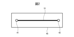
- FIG. 2 is a top view of an object having the characteristic portion.
- the characteristic portion 51 is a straight line drawn on the top surface of the object 45.
- the length L0 and width of the characteristic portion 51 are known and are stored in a memory unit 29 of the control device 20, which will be described later.
- the characteristic portion 51 may have other visually recognizable configurations.
- the characteristic portion 51 may be a recess, notch, protrusion, or ridge formed on the top surface of the object 45. As will be described later, the characteristic portion 51 does not have to be a straight line as long as the shape is known.
- the robot 10 is controlled by a control device 20.
- the control device 20 controls multiple motors using the detection results of multiple detection units.
- the control device 20 is a computer equipped with a CPU (Central Processing Unit), a memory unit 29, etc., which are connected to each other via a bus.
- CPU Central Processing Unit
- memory unit 29 etc.
- the storage unit 29 may be a volatile memory, a non-volatile memory, a hard disk drive, or a solid state drive.
- the storage unit 29 also stores the operation programs described below for operating the robot 10, and various data.
- the control device 20 controls the imaging of the camera 15 and performs image processing on the images captured by the camera 15.
- the CPU of the control device 20 includes a moving unit 21 that moves the robot 10, an imaging unit 22 that uses the camera 15 to capture an image 16 of the characteristic portion 51 at least once while the robot 10 is being moved by the moving unit 21, and a trajectory error calculation unit 23 that calculates a trajectory error ⁇ T of the robot 10 based on the captured characteristic portion 51 in the image 16 and a predetermined point P0 in the image 16.
- the CPU of the control device 20 further includes a graph creation unit 24 that creates a relationship between the moving distance L of the robot 10 and the trajectory error ⁇ T when the imaging unit 22 causes the camera 15 to capture the image 16 multiple times, and an additional instruction unit 25 that instructs the robot 10 to add a teaching point when the trajectory error ⁇ T is greater than a predetermined threshold value ⁇ T0.
- the teaching operation panel 30 is also a computer and similarly includes a CPU, memory, etc.
- the teaching operation panel 30 includes a display unit 31, such as a display, that displays various processes of the control device 20 and the teaching operation panel 30.
- the teaching operation panel 30 includes an input unit 32, such as a touch panel, that inputs various operations by the operator.
- the CPU of the teaching operation panel 30 may have the movement unit 21, the imaging unit 22, the trajectory error calculation unit 23, the graph creation unit 24, and the additional instruction unit 25.
- the CPU of the control device 20 may have at least one of the movement unit 21, the imaging unit 22, the trajectory error calculation unit 23, the graph creation unit 24, and the additional instruction unit 25, and the CPU of the teaching operation panel 30 may have the remaining of the movement unit 21, the imaging unit 22, the trajectory error calculation unit 23, the graph creation unit 24, and the additional instruction unit 25.
- the moving unit 21, the imaging unit 22, the trajectory error calculation unit 23, the graph creation unit 24, and the additional instruction unit 25 possessed by the CPU of the control device 20 and/or the teaching pendant 30 are functional modules realized by, for example, a computer program executed on the CPU.
- the computer program for executing the processing of the moving unit 21, the imaging unit 22, the trajectory error calculation unit 23, the graph creation unit 24, and the additional instruction unit 25 possessed by the CPU of the control device 20 and/or the teaching pendant 30 may be provided in a form recorded on a computer-readable recording medium such as a semiconductor memory, a magnetic recording medium, or an optical recording medium.
- the control device 20 may also be connected to a display unit, such as a display or CRT, that displays various computer processes. Furthermore, the control device 20 may also be connected to an input unit, such as a mouse and keyboard, that inputs various operations by the operator.
- a display unit such as a display or CRT
- an input unit such as a mouse and keyboard
- FIG. 1B is a flowchart showing the operation of the robot system shown in FIG. 1A. Below, the operation of the robot system 1a will be described with reference to FIG. 1B. It should be noted that two teaching points are taught in the operation program of the robot 10. One teaching point is one end 41 of the characteristic part 51 which is the start position of the operation of the robot 10, and the other teaching point is the other end 42 of the characteristic part 51 which is the end position of the operation of the robot 10. Therefore, these teaching points may be referred to as teaching points 41 and 42, respectively.
- One teaching point 41 is taught so that a specific point P0 of the image 16 to be captured by the camera 15 coincides with one end 41 of the characteristic portion 51.
- the other teaching point 42 is taught so that a specific point P0 of the image 16 to be captured by the camera 15 coincides with the other end 42 of the characteristic portion 51.
- Such an operation program is stored in the memory unit 29.
- the camera 15 is positioned in advance so that at least a portion of the characteristic portion 51 is within the field of view of the camera 15.
- step S11 of FIG. 1B the operator sets the total number of times N to capture images (N is a natural number) using the input unit 32.
- step S12 the movement unit 21 moves the robot 10 based on the created operation program. That is, the wrist 13 of the robot 10 moves linearly along the characteristic portion 51. Note that the movement speed of the robot 10 is determined according to the overall length L0 of the characteristic portion 51 and the total number of times N to capture images, so that the camera completes N images at regular time intervals while the robot 10 moves from one end 41 to the other end 42 of the characteristic portion 51.
- FIG. 3 is a perspective view for explaining the operation of the robot system in the first embodiment.
- a characteristic part 51 corresponding to the target trajectory of the robot 10 and an actual trajectory 52 that the robot 10 actually moves are shown.
- step S13 while the robot 10 is moving, the imaging unit 22 causes the camera 15 to capture the first image (i-th image, where i is the current number of images captured and is a natural number less than or equal to the total number of images captured N) of the characteristic portion 51.
- the captured image 16 is stored in the memory unit 29.
- the moving unit 21 also calculates the travel distance L1 (travel distance Li) from one end 41 of the characteristic portion 51 of the robot 10 when the camera 15 captures the image.
- the travel distance Li may be calculated from the detection results of multiple detection units provided on each of the multiple motors, or may be calculated from the elapsed time after the robot 10 has moved and the moving speed of the robot 10.
- the travel distance Li is stored in the memory unit 29 in association with the corresponding i-th image 16.
- step S14 it is confirmed whether the current number of times i to capture images is the same as the total number of times N to capture images. If the current number of times i to capture images is different from the total number of times N to capture images, the process proceeds to step S15, where "1" is added to the current number of times i to capture images, and the process proceeds to step S13. Then, in step S13, the second (ith ( ⁇ i+1)) image of the characteristic portion 51 is captured and the travel distance Li is calculated in the same manner, and these are associated and stored in the storage unit 29. The process is then repeated until the current number of times i to capture images is the same as the total number of times N to capture images. When the current number of times i to capture images is the same as the total number of times N to capture images, the process proceeds to step S16, where the movement unit 21 stops the robot 10 at the other end 42 of the characteristic portion 51.
- FIG. 4 is a diagram showing an image taken by the camera. Strictly speaking, the image 16 shown in FIG. 4 is the i-th image taken after the first image, so one end 41 of the characteristic portion 51 is not shown in the image 16 in FIG. 4.
- the specified point P0 is the center of the image 16. However, the specified point P0 may be set at another location within the image 16.
- the trajectory error calculation unit 23 draws a perpendicular line from the specified point P0 to the characteristic feature 51 in the i-th image 16, and obtains the length of this perpendicular line as the trajectory error ⁇ Ti.
- the trajectory error ⁇ Ti is associated with the corresponding image 16 and the movement distance Li and stored in the memory unit 29. Note that the trajectory error ⁇ Ti is assigned a plus or minus sign depending on the positional relationship between the specified point P0 and the characteristic feature 51.
- the trajectory error ⁇ T1 in the first image 16 is approximately zero.
- step S18 it is confirmed whether the current number of times i to capture images is the same as the total number of times N to capture images. If the current number of times i to capture images is different from the total number of times N to capture images, the process proceeds to step S19, where "1" is added to the current number of times i to capture images, and the process proceeds to step S17. Then, in step S17, the trajectory error ⁇ Ti is similarly calculated from the image 16 obtained in the second capture (ith ( ⁇ i+1)th capture), and similarly stored in the storage unit 29. The process is then repeated until the current number of times i to capture images is the same as the total number of times N to capture images.
- the trajectory error calculation unit 23 calculates the trajectory error ⁇ Ti, so that the operator can easily grasp the trajectory error ⁇ Ti of the robot 10. This allows the operator to independently determine whether or not each trajectory error ⁇ Ti is large, for example.
- a visually recognizable feature 51 is captured by a camera 15, and a trajectory error ⁇ Ti is calculated based on the positional relationship between the feature 51 and a predetermined point P0 in the image 16.
- the feature 51 corresponds to the target trajectory of the robot 10
- the predetermined point P0 corresponds to the actual trajectory 52.
- the target trajectory and the actual trajectory 52 coexist in one image 16, and therefore the trajectory error ⁇ Ti can be obtained directly. Therefore, in the present disclosure, the trajectory error ⁇ Ti can be obtained more accurately than when the error between the target trajectory created from the movement command of the robot 10 and the actual trajectory created by the camera is calculated.
- step S20 the graph creation unit 24 creates a graph based on the relationship between the movement distance Li and the trajectory error ⁇ Ti of the robot 10 stored in the memory unit 29.
- FIG. 5A is a diagram showing the relationship between the movement distance Li of the robot 10 and the trajectory error.
- the horizontal axis indicates the movement distance Li of the robot 10, which corresponds to the characteristic portion 51.
- the vertical axis indicates the trajectory error ⁇ Ti, and the dashed line 52 corresponds to the actual trajectory 52. Therefore, in other words, the graph creation unit 24 creates a graph of the actual trajectory 52.
- the greater the total number of imaging times N the more precise the actual trajectory 52 that can be created.
- the graph creation unit 24 creating a graph of the actual trajectory 52, the operator can visually determine the behavior of the trajectory error ⁇ Ti along the characteristic portion 51. Therefore, it is easy to find defects in the actual operation of the robot 10, such as a large trajectory error ⁇ Ti near a specific point on the characteristic portion 51.
- one end 41 and the other end 42 of the characteristic portion 51 correspond to teaching points of the robot 10. That is, in FIG. 5A etc., the behavior of the robot 10 between two adjacent teaching points 41, 42 is represented as an actual trajectory 52. Then, if the trajectory error ⁇ Ti between the teaching points 41, 42 is large, it is preferable to set an additional teaching point Q between the teaching points 41, 42.
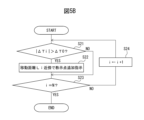
- FIG. 5B is a flowchart showing another operation of the robot system. The flowchart shown in FIG. 5B is executed appropriately after the flowchart shown in FIG. 1B is completed.
- step S21 the additional instruction unit 25 determines whether the absolute value
- the predetermined value ⁇ T0 is a value obtained by experiment or simulation. If the absolute value
- step S23 it is confirmed whether the current number of times i to capture images is the same as the total number of times N to capture images. If the current number of times i to capture images is different from the total number of times N to capture images, the process proceeds to step S124, where "1" is added to the current number of times i to capture images, and the process proceeds to step S21. Then, in step S21, the absolute value
- an additional teaching point Q is shown on the moving distance Li corresponding to a trajectory error ⁇ Ti larger than a predetermined value ⁇ T0. Therefore, the operator need only actually add the additional teaching point Q in accordance with the instructions of the additional instruction unit 25. It will be seen that when an additional teaching point Q is added, the trajectory error ⁇ Ti in the vicinity of the additional teaching point Q can be significantly reduced. Note that the additional instruction unit 25 may also instruct to teach multiple additional teaching points in the vicinity of the moving distance Li.
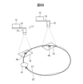
- FIG. 6A is a perspective view for explaining the operation of the robot system in the second embodiment.
- the characteristic portion 51' of the object 45 is a circle with a known diameter.
- the operation program of the robot 10 teaches only a point 41 located on the circumference of the circle as a single teaching point 41. Strictly speaking, this teaching point 41 is taught so that a specific point P0 of an image 16 to be captured by the camera 15 coincides with the point 41 located on the circumference.
- FIG. 6A also shows an actual trajectory 52'.
- FIG. 6B is a diagram showing another image taken by the camera.
- the trajectory error calculation unit 23 draws a perpendicular line from a predetermined point P0 in the image 16 captured by the camera 15 to the tangent (indicated by a dashed line) of the characteristic portion 51', and obtains the length of the perpendicular line as the trajectory error ⁇ Ti.
- the movement distance Li may be calculated from the detection results of multiple detection units provided on each of the multiple motors, or may be calculated from the elapsed time after the movement of the robot 10, the movement speed of the robot 10, and the diameter of a circle serving as the characteristic portion 51'.
- the characteristic portion 51' may be a known ellipse or a known curve. Furthermore, the characteristic portion 51' may at least partially include such a known curve.
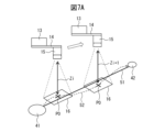
- FIG. 7A is a perspective view for explaining the operation of the robot system in the third embodiment.
- the camera 15 in FIG. 7A is a camera, such as a 3D camera, that can measure the distance Z between the camera 15 and a subject (corresponding to the image 16 in FIG. 7A).
- the camera 15 determines the three-dimensional positions of one end 41 and the other end 42 of the characteristic portion 51, that is, the three-dimensional positions of the teaching points 41, 42.
- the movement unit 21 determines the three-dimensional function of the characteristic portion 51 using a known method. Thereafter, an operation program is created so that the robot 10 moves linearly parallel to the characteristic portion 51 from one end 41 to the other end 42 of the characteristic portion 51, and this is stored in the memory unit 29.
- the distance between the camera 15 and one end 41 of the characteristic portion 51 detected by imaging is stored in the memory unit 29 as distance Z0.
- the movement unit 21 moves the robot 10 according to the operation program, and the imaging unit 22 captures images N times at regular time intervals while the robot 10 is moving. Then, in step S13, in addition to calculating the i-th image capture and the movement distance Li, the distance Zi between the camera 15 and the characteristic feature 51 at the time of the i-th image capture is also obtained.
- step S17 the additional trajectory error ⁇ Ti' is calculated as
- the additional trajectory error ⁇ Ti' is not calculated directly from the image 16. Therefore, in the third embodiment, it is not necessary to use the camera 15 as a 3D camera, and a distance sensor may be used instead of the camera 15. Alternatively, in the third embodiment, the camera 15 as a 2D camera and a distance sensor may be used in combination.
- step S20 the graph creation unit 24 displays a graph of the relationship between the distance Zi and the additional trajectory error ⁇ Ti', in addition to the relationship between the moving distance Li of the robot 10 and the trajectory error ⁇ Ti stored in the memory unit 29.
- FIG. 7B is a diagram showing the relationship between the distance between the camera and the characteristic part and the trajectory error. As shown in FIG. 7B, a graph can be created with the moving distance Li on the horizontal axis and the additional trajectory error ⁇ Ti' on the vertical axis. In this case, the trajectory error ⁇ Ti and the additional trajectory error ⁇ Ti' are found, so that the difference between the target trajectory and the actual trajectory can be grasped in three dimensions.
- the additional instruction unit 25 instructs to additionally teach a teaching point Q' on or near the corresponding moving distance Li. It will be understood that in this case as well, the same effect as described above can be obtained.
- FIG. 8 is a schematic diagram of a robot system based on another embodiment.
- an openable and closable hand 14' is provided on the wrist 13.
- the hand 14' grasps an object 45 similar to that described above.
- the hand 14' may be opened and closed by one of the multiple motors of the robot 10.
- the camera 15 is not provided on the robot 10, but is fixed independently of the robot 10.
- the object 45 is then positioned in advance so that the image 16 to be captured by the camera 15 includes one end 41 of the characteristic portion 51. It is clear that with this configuration as well, the same effect as described above can be obtained.
- the trajectory accuracy of the robot can be easily confirmed. Furthermore, by teaching additional teaching points to locations where the trajectory accuracy is low, an appropriate number of teaching points can be taught.
- (Appendix 1) Robots and A camera and A moving unit that moves the robot; an imaging unit that captures an image of a characteristic part by the camera at least once while the robot is being moved by the moving unit; a trajectory error calculation unit that calculates a trajectory error of the robot based on the captured characteristic portion in the image and a predetermined point in the image.
- (Appendix 2) the camera is mounted on the robot and the object including the feature is located at a fixed position; or 2.
- Appendix 4 4.
- Appendix 5 5.
- the trajectory error calculation unit calculates the length of a line segment extending from the specified point to a tangent to the curve as the trajectory error.
- (Appendix 10) A moving unit that moves the robot; an imaging unit that captures an image of a characteristic part at least once with a camera while the robot is being moved by the moving unit; a trajectory error calculation unit that calculates a trajectory error of the robot based on the captured characteristic portion in the image and a predetermined point in the image.
- the camera is mounted on the robot and the object including the feature is located at a fixed position; or 11.
- the control device of claim 10 wherein the camera is positioned at a fixed position and the object is provided on the robot.
- the control device according to any one of appendixes 10 to 12, wherein the feature portion includes at least one of a straight line having a predetermined shape and a curved line having a predetermined shape.
- Appendix 14 14. The control device according to claim 13, wherein, when the characteristic portion includes the straight line, the trajectory error calculation unit calculates, as the trajectory error, a length of a perpendicular line extending from the predetermined point to the straight line.
- the trajectory error calculation unit calculates, as the trajectory error, a length of a line segment extending from the predetermined point to a tangent to the curve. (Appendix 16) 16.
- the control device according to any one of appendices 10 to 15, further comprising a graph creation unit that creates a relationship between the moving distance of the robot and the trajectory error when the imaging unit captures the image multiple times.
- Appendix 17 17.
- the control device according to any one of appendices 10 to 16, further comprising an addition instruction unit that instructs the robot to add a teaching point when the trajectory error is greater than a predetermined threshold.
- the camera is a 3D camera that measures a distance between the camera and the object;
- the control device according to any one of appendices 10 to 17, wherein the trajectory error calculation unit calculates an additional trajectory error based on the distance and a predetermined distance between the 3D camera and the characteristic portion.
Landscapes
- Engineering & Computer Science (AREA)
- Robotics (AREA)
- Mechanical Engineering (AREA)
- Human Computer Interaction (AREA)
- Manipulator (AREA)
Abstract
ロボットシステムは、ロボットと、カメラと、前記ロボットを移動させる移動部と、前記ロボットが移動しているときに、特徴部の画像を前記カメラにより少なくとも一回、撮像させる撮像部と、前記画像における撮像された前記特徴部と前記画像における所定点とに基づいて、前記ロボットの軌跡誤差を算出する軌跡誤差算出部とを含む。
Description
本開示は、ロボットシステムおよび制御装置に関する。
ロボットに作業を行わせる場合には、複数の教示点を予め教示することによりロボットの動作経路を設定している。アーク溶接やシーリングなどのアプリケーションにおいては、ロボットの動作経路上に多数の教示点を設定している。特許文献1においては、ロボットの軌跡の精度を向上させるために、ロボットの実際の移動軌跡と、移動指令によって規定されるロボットの基準軌跡との間のズレ量を取得することが開示されている。
しかしながら、隣接する二つの教示点の間におけるロボットの軌跡については、必ずしも明確でない場合がある。従って、操作者は、ロボットの動作経路を設定する際に、どの程度の数の教示点を設定すべきであるかを判断できない。多数の教示点を教示する場合には、ロボットの軌跡の精度は向上するものの、教示作業の回数が増えて時間がかかるという問題がある。
それゆえ、適切な数の教示点を教示すべく、ロボットの軌跡精度を確認することのできるロボットシステムおよび制御装置が望まれている。
本開示の1番目の態様によれば、ロボットと、カメラと、前記ロボットを移動させる移動部と、該移動部により前記ロボットが移動しているときに、特徴部の画像を前記カメラにより少なくとも一回、撮像させる撮像部と、前記画像における撮像された前記特徴部と前記画像における所定点とに基づいて、前記ロボットの軌跡誤差を算出する軌跡誤差算出部とを具備する、ロボットシステムが提供される。
さらに、本開示の他の態様によれば、ロボットを移動させる移動部と、該移動部により前記ロボットが移動しているときに、特徴部の画像をカメラにより少なくとも一回、撮像させる撮像部と、前記画像における撮像された前記特徴部と前記画像における所定点とに基づいて、前記ロボットの軌跡誤差を算出する軌跡誤差算出部とを具備する、制御装置が提供される。
本開示の目的、特徴及び利点は、添付図面に関連した以下の実施形態の説明により一層明らかになろう。
以下、添付図面を参照して本開示の実施の形態を説明する。全図面に渡り、対応する構成要素には共通の参照符号を付す。
図1Aは第一の実施形態に基づくロボットシステムの略図である。図1Aに示されるように、第一の実施形態に基づくロボットシステム1aは、ロボット10と、ロボット10を制御する制御装置20と、制御装置20を通じてロボット10を操作する教示操作盤30とを主に含んでいる。ただし、操作者が制御装置20を通じてロボット10を操作する場合には、ロボットシステム1a(および後述するロボットシステム1b)は教示操作盤30を含んでいなくてもよい。なお、ロボット10と制御装置20との間、および制御装置20と教示操作盤30との間は、有線または無線により接続されるものとする。
図1Aは第一の実施形態に基づくロボットシステムの略図である。図1Aに示されるように、第一の実施形態に基づくロボットシステム1aは、ロボット10と、ロボット10を制御する制御装置20と、制御装置20を通じてロボット10を操作する教示操作盤30とを主に含んでいる。ただし、操作者が制御装置20を通じてロボット10を操作する場合には、ロボットシステム1a(および後述するロボットシステム1b)は教示操作盤30を含んでいなくてもよい。なお、ロボット10と制御装置20との間、および制御装置20と教示操作盤30との間は、有線または無線により接続されるものとする。
ロボット10は、複数のモータを備えた例えば六自由度の垂直多関節ロボットでありうる。図1Aに示されるロボット10においては、複数のモータのそれぞれにより駆動される複数のアーム12がロボットベース11上に公知の手法で配置されている。そして、最先端のアームには、手首部13が備えられている。
図面には示さないものの、複数のモータのそれぞれは、対応する軸の位置および/または速度を検出する検出部、例えばエンコーダを備えている。同様に、図面には示さないものの、複数のモータのそれぞれには各種のセンサ、例えば温度センサなどが備えられていてもよい。
ロボット10の手首部13には、棒材14が取付けられており、棒材14の先端にはカメラ15が設けられている。第一の実施形態におけるカメラ15は例えば2Dカメラである。なお、棒材14を使用することなしに、カメラ15が手首部13に直接的に取付けられていてもよい。
図1Aに示されるように、カメラ15の下方には、固定位置に設置された対象物45が配置されている。図1Aにおいては対象物45はテーブル上に配置されている板材である。しかしながら、対象物45がテーブルの天板自体であってもよい。また、対象物45が床に直接的に配置されていてもよい。
対象物45は、ロボット10の目標軌跡に相当する特徴部51を備えている。図2は特徴部を備えた対象物の頂面図である。第一の実施形態においては、特徴部51は対象物45の上面に描かれた直線である。特徴部51の長さL0および幅は既知であり、制御装置20の後述する記憶部29に記憶されている。なお、特徴部51は視覚的に認識可能な他の構成であってもよい。例えば特徴部51は、対象物45の上面に形成された凹部、切欠、突起、隆起部などであってもよい。なお、後述するように、形状が既知であれば、特徴部51は直線である必要はない。
ロボット10は、制御装置20により制御される。公知であるように、制御装置20は、複数の検出部の検出結果を用いて複数のモータを制御する。制御装置20は、バスを介して互いに接続されたCPU(Central Processing Unit)、記憶部29などを備えたコンピュータである。
記憶部29は揮発性メモリ、不揮発性メモリ、ハードディスクドライブ、ソリッドステートドライブのいずれであってもよい。また、記憶部29は、ロボット10を動作させる後述の動作プログラムおよび各種のデータを記憶するものとする。さらに、制御装置20は、カメラ15の撮像制御およびカメラ15により撮像された画像についての画像処理を行うものとする。
図1Aに示されるように、制御装置20のCPUは、ロボット10を移動させる移動部21と、移動部21によりロボット10が移動しているときに、カメラ15を用いて特徴部51の画像16を少なくとも一回、撮像させる撮像部22と、画像16における撮像された特徴部51と画像16における所定点P0とに基づいて、ロボット10の軌跡誤差ΔTを算出する軌跡誤差算出部23とを含んでいる。
さらに、制御装置20のCPUは、撮像部22がカメラ15に画像16を複数回、撮像させる場合に、ロボット10の移動距離Lと軌跡誤差ΔTとの関係を作成するグラフ作成部24と、軌跡誤差ΔTが所定の閾値ΔT0よりも大きい場合には、ロボット10の教示点を追加するよう指示する追加指示部25をさらに含んでいる。
教示操作盤30もコンピュータであり、CPU、メモリ等を同様に備えている。教示操作盤30は、制御装置20および教示操作盤30の各種の処理を表示する表示部31、例えばディスプレイを備えている。さらに、教示操作盤30は、操作者の各所の操作を入力する入力部32、例えばタッチパネルを備えている。
なお、制御装置20のCPUの代わりに、教示操作盤30のCPUが移動部21、撮像部22、軌跡誤差算出部23、グラフ作成部24および追加指示部25を有していてもよい。あるいは、制御装置20のCPUが移動部21、撮像部22、軌跡誤差算出部23、グラフ作成部24および追加指示部25のうちの少なくとも一つを有していて、教示操作盤30のCPUが移動部21、撮像部22、軌跡誤差算出部23、グラフ作成部24および追加指示部25のうちの残りを有していてもよい。
制御装置20および/または教示操作盤30のCPUが有する移動部21、撮像部22、軌跡誤差算出部23、グラフ作成部24および追加指示部25は、例えばCPU上で実行されるコンピュータプログラムにより実現される機能モジュールである。制御装置20および/または教示操作盤30のCPUが有する移動部21、撮像部22、軌跡誤差算出部23、グラフ作成部24および追加指示部25の処理を実行するためのコンピュータプログラムは、半導体メモリ、磁気記録媒体または光記録媒体といった、コンピュータ読取可能な記録媒体に記録された形で提供されてもよい。
なお、制御装置20にも、コンピュータの各種の処理を表示する表示部、例えばディスプレイ、CRT等が接続されていてもよい。さらに、制御装置20にも、操作者の各所の操作を入力する入力部、例えばマウス、キーボードが接続されていてもよい。
図1Bは図1Aに示されるロボットシステムの動作を示すフローチャートである。以下、図1Bを参照して、ロボットシステム1aに関する動作について説明する。なお、ロボット10の動作プログラムにおいては二つの教示点が教示されているものとする。一方の教示点はロボット10の動作の開始位置としての特徴部51の一端41であり、他方の教示点はロボット10の動作の終了位置としての特徴部51の他端42である。従って、これら教示点をそれぞれ教示点41、42と呼ぶ場合がある。
一方の教示点41は、カメラ15で撮像されるべき画像16の所定点P0が特徴部51の一端41に一致するように教示される。同様に、他方の教示点42は、カメラ15で撮像されるべき画像16の所定点P0が特徴部51の他端42に一致するように教示される。そして、そのような動作プログラムは記憶部29に記憶されるものとする。さらに、特徴部51の少なくとも一部分がカメラ15の視野に入るようにカメラ15を予め位置決めする。
図1BのステップS11において、操作者は入力部32を用いて総撮像回数N(Nは自然数)を設定する。次いで、ステップS12においては、移動部21は、作成された動作プログラムに基づいてロボット10を移動させる。つまり、ロボット10の手首部13を特徴部51に沿って線形移動させる。なお、ロボット10が特徴部51の一端41から他端42まで移動する間にカメラが一定の時間間隔でN回の撮像を終了するために、ロボット10の移動速度は特徴部51全体の長さL0と総撮像回数Nとに応じて定まるものとする。
図3は第一の実施形態においてロボットシステムの動作を説明するための斜視図である。図3においては、ロボット10の目標軌跡に対応する特徴部51と、ロボット10が実際に移動した実軌跡52とが示されている。
ステップS13において、ロボット10が移動しつつ、撮像部22は、カメラ15に特徴部51に対する第1回目(第i回目、iは現在の撮像回数で、総撮像回数N以下の自然数)の撮像を実行させる。撮像された画像16は記憶部29に記憶される。また、移動部21は、カメラ15の撮像時におけるロボット10の特徴部51の一端41からの移動距離L1(移動距離Li)を算出する。移動距離Liは、複数のモータのそれぞれに備えられた複数の検出部の検出結果から算出してもよく、または、ロボット10の移動後の経過時間とロボット10の移動速度とから算出してもよい。移動距離Liは、対応する第i回目の画像16と関連付けて記憶部29に記憶される。
次いで、ステップS14において、現在の撮像回数iが総撮像回数Nと同じであるかを確認する。現在の撮像回数iが総撮像回数Nとは異なる場合には、ステップS15に進んで、現在の撮像回数iに「1」を加算して、ステップS13に進む。そして、ステップS13において、特徴部51に対する第2回目(第i(←i+1)回目)の撮像と移動距離Liの算出とを同様に行い、これらを関連付けて記憶部29に記憶する。そして、現在の撮像回数iが総撮像回数Nと同じになるまで処理を繰返す。現在の撮像回数iが総撮像回数Nと同じになると、ステップS16に進んで、移動部21は、ロボット10を特徴部51の他端42で停止させる。
次いで、ステップS17において、軌跡誤差算出部23は、第1回目(第i回目)の軌跡誤差ΔT1(軌跡誤差ΔTi)を算出する。図4はカメラの画像を示す図である。厳密には、図4に示される画像16は第1回目よりも後で撮像された第i回目の画像であるので、図4の画像16には特徴部51の一端41は表されない。図4においては、所定点P0は画像16の中心である。ただし、所定点P0を画像16内の他の場所に設定してもよい。
図4に示されるように、軌跡誤差算出部23は、第i回目の画像16において所定点P0から特徴部51に向かう垂線を引き、この垂線の長さを軌跡誤差ΔTiとして求める。軌跡誤差ΔTiは対応する画像16および移動距離Liに関連付けられて記憶部29に記憶される。なお、所定点P0と特徴部51との間の位置関係に応じて、軌跡誤差ΔTiにはプラス符号またはマイナス符号が付されるものとする。また、第1回目の画像16はロボット10の移動開始時または移動開始直後に撮像されるので、第1回目の画像16における軌跡誤差ΔT1は概ねゼロである。
次いで、ステップS18において、現在の撮像回数iが総撮像回数Nと同じであるかを確認する。現在の撮像回数iが総撮像回数Nとは異なる場合には、ステップS19に進んで、現在の撮像回数iに「1」を加算して、ステップS17に進む。そして、ステップS17において、第2回目(第i(←i+1)回目)の撮像で得られた画像16から、軌跡誤差ΔTiを同様に求めて、記憶部29に同様に記憶する。そして、現在の撮像回数iが総撮像回数Nと同じになるまで処理を繰返す。
このように、軌跡誤差算出部23が軌跡誤差ΔTiを算出することにより、操作者はロボット10の軌跡誤差ΔTiを容易に把握することができる。これにより、例えば操作者は、それぞれの軌跡誤差ΔTiが大きいか否かを独自に判断することも可能である。
本開示においては、視覚的に認識可能な特徴部51をカメラ15で撮像し、その画像16における特徴部51と所定点P0との間の位置関係に基づいて軌跡誤差ΔTiを算出している。そして、特徴部51はロボット10の目標軌跡に相当すると共に、所定点P0は実軌跡52に相当している。つまり、本開示においては、一つの画像16内に、目標軌跡と実軌跡52とが併存しており、従って、軌跡誤差ΔTiを直接的に求めることができる。それゆえ、ロボット10の移動指令から作成された目標軌跡とカメラで作成された実軌跡との間の誤差を算出する場合と比較すると、本開示においては、軌跡誤差ΔTiをより正確に求めることができる。
次いで、ステップS20において、グラフ作成部24が、記憶部29に記憶されたロボット10の移動距離Liと軌跡誤差ΔTiとの関係に基づいてグラフを作成する。図5Aはロボットの移動距離と軌跡誤差との関係を示す図である。図5Aにおいて、横軸はロボット10の移動距離Liを示しており、特徴部51に対応する。また、縦軸は軌跡誤差ΔTiを示しており、破線52は実軌跡52に相当する。従って、グラフ作成部24は、実軌跡52のグラフを作成すると言い換えることもできる。また、総撮像回数Nが多いほど、より精密な実軌跡52が作成できるのは、当業者であれば明らかであろう。
このように、グラフ作成部24が実軌跡52のグラフを作成することにより、操作者は特徴部51に沿った軌跡誤差ΔTiの挙動を視覚的に判断することができる。従って、例えば特徴部51上の特定箇所の近傍で軌跡誤差ΔTiが大きくなる等、ロボット10の実際の動作における不具合等を容易に発見することができる。
前述したように特徴部51の一端41および他端42は、ロボット10の教示点に相当する。つまり、図5A等においては隣接する二つの教示点41、42の間におけるロボット10の挙動が実軌跡52として表されている。そして、教示点41、42の間において軌跡誤差ΔTiが大きい場合には、追加の教示点Qを教示点41、42の間に設定するのが好ましい。
ここで、図5Bはロボットシステムの動作を他の示すフローチャートである。図5Bに示されるフローチャートは、図1Bに示されるフローチャートの終了後に適宜行われるものとする。
ステップS21において、追加指示部25は、軌跡誤差ΔTiの絶対値|ΔTi|が所定値ΔT0より大きいか否かを判定する。所定値ΔT0は実験またはシミュレーションにより求められた値である。軌跡誤差ΔTiの絶対値|ΔTi|が所定値ΔT0より大きい場合には、対応する移動距離Li上またはその近傍で教示点Qを追加で教示するよう指示する。
そして、ステップS23において、現在の撮像回数iが総撮像回数Nと同じであるかを確認する。現在の撮像回数iが総撮像回数Nとは異なる場合には、ステップS124進んで、現在の撮像回数iに「1」を加算して、ステップS21に進む。そして、ステップS21において、次の軌跡誤差ΔTi(i←i+1)の絶対値|ΔTi|を所定値ΔT0と同様に比較する。そして、現在の撮像回数iが総撮像回数Nと同じになるまで処理を繰返す。
図5Aには所定値ΔT0より大きい軌跡誤差ΔTiに対応する移動距離Li上に、追加の教示点Qが示されている。従って、操作者は、追加指示部25の指示に従って、追加の教示点Qを実際に追加すればよい。追加の教示点Qを追加した場合には、追加の教示点Q近傍における軌跡誤差ΔTiを大幅に低下できるのが分かるであろう。なお、追加指示部25は、移動距離Liの近傍に複数の追加の教示点を教示するよう指示してもよい。
図6Aは第二の実施形態においてロボットシステムの動作を説明するための斜視図である。第二の実施形態においては、対象物45の特徴部51’は直径が既知の円である。この場合には、ロボット10の動作プログラムは、円周上に位置する点41のみが一つの教示点41として教示されている。厳密に言えば、この教示点41は、カメラ15で撮像されるべき画像16の所定点P0が円周上に位置する点41に一致するように教示される。また、図6Aには、実軌跡52’も示されている。
図6Bはカメラの他の画像を示す図である。図6Bに示されるように、軌跡誤差算出部23は、カメラ15で撮像された画像16内の所定点P0から特徴部51’の接線(破線で示される)に向かう垂線を引き、その垂線の長さを軌跡誤差ΔTiとして取得する。また、移動距離Liは、複数のモータのそれぞれに備えられた複数の検出部の検出結果から算出してもよく、または、ロボット10の移動後の経過時間とロボット10の移動速度と特徴部51’としての円の直径とから算出してもよい。特徴部51’は、既知の楕円または既知の曲線であってもよい。さらに、特徴部51’が、そのような既知の曲線を少なくとも部分的に含んでいてもよい。
図7Aは第三の実施形態においてロボットシステムの動作を説明するための斜視図である。図7Aにおけるカメラ15は、カメラ15と被写体(図7Aにおける画像16に相当)との間の距離Zを計測することのできるカメラ、例えば3Dカメラである。
この場合には、カメラ15により特徴部51の一端41および他端42の三次元位置、つまり教示点41、42の三次元位置をそれぞれ求める。そして、移動部21は、公知の手法で、特徴部51の三次元関数を求める。その後、ロボット10が特徴部51の一端41から他端42まで特徴部51に対して平行に線形移動するように動作プログラムを作成して記憶部29に記憶させる。また、撮像により検出されたカメラ15と特徴部51の一端41との間の距離を距離Z0として記憶部29に記憶する。
図1Aを参照して説明したのと同様に、移動部21は動作プログラムに従ってロボット10を移動させ、ロボット10の移動中に撮像部22が一定の時間間隔でN回だけ撮像する。そして、ステップS13においては、第i番目の撮像、移動距離Liの算出に加え、第i番目の撮像時におけるカメラ15と特徴部51との間の距離Ziも取得する。
ステップS17においては、追加の軌跡誤差ΔTi’を|Zi-Z0|として算出する。第三の実施形態においては、追加の軌跡誤差ΔTi’は画像16から直接的に算出されない。従って、第三の実施形態においては、3Dカメラとしてのカメラ15を使用する必要はなく、カメラ15の代わりに距離センサを用いてもよい。あるいは、第三の実施形態では、2Dカメラとしてのカメラ15と距離センサとを併用するようにしてもよい。
さらに、ステップS20においては、グラフ作成部24が、記憶部29に記憶されたロボット10の移動距離Liと軌跡誤差ΔTiとの関係に加えて、距離Ziと追加の軌跡誤差ΔTi’との関係をグラフ表示する。図7Bはカメラおよび特徴部の間の距離と軌跡誤差との関係を示す図である。図7Bに示されるように、移動距離Liを横軸とすると共に、追加の軌跡誤差ΔTi’を縦軸とするグラフを作成することができる。この場合には、軌跡誤差ΔTiおよび追加の軌跡誤差ΔTi’が求められるので、目標軌跡と実軌跡との間の差を三次元的に把握することができる。
さらに、第三の実施形態においては、図5Bを参照して説明したように、追加の軌跡誤差ΔTi’の絶対値|ΔTi’|が所定値ΔT0’よりも大きい場合には、追加指示部25は、対応する移動距離Li上またはその近傍で教示点Q’を追加で教示するよう指示する。この場合にも、前述したのと同様な効果が得られるのが分かるであろう。
図8は他の実施形態に基づくロボットシステムの略図である。図8に示されるロボットシステム1bおいては、手首部13に開閉可能なハンド14’が備えられている。そして、ハンド14’は前述したのと同様な対象物45を把持している。ハンド14’は、ロボット10の複数のモータのうちの一つで開閉するようにしてもよい。
また、カメラ15はロボット10に備えられておらず、ロボット10とは独立して、固定されている。そして、カメラ15により撮像されるべき画像16が特徴部51の一端41を含むように対象物45を予め位置決めする。このような構成においても、前述したのと同様な効果が得られるのは明らかであろう。
以上説明した少なくとも一つの実施形態の効果としては、ロボットの軌跡精度を容易に確認することができる。そして、軌跡精度が低い箇所に追加の教示点を教示することにより、適切な数の教示点を教示することができる。
本開示の実施形態について詳述したが、本開示は上述した個々の実施形態に限定されるものではない。これらの実施形態は、発明の要旨を逸脱しない範囲で、または請求の範囲に記載された内容とその均等物から導き出される本発明の思想および趣旨を逸脱しない範囲で、種々の追加、置き換え、変更、部分的削除などが可能である。例えば、上述した実施形態において、各動作の順序や各処理の順序は、一例として示したものであり、これらに限定されるものではない。また、上述した実施形態の説明に数値又は数式が用いられている場合も同様である。さらに、前述した実施形態の幾つかを適宜組み合わせることは本開示の範囲に含まれる。
上記実施形態および変型例に関し、更に以下の付記を開示する。
(付記1)
ロボットと、
カメラと、
前記ロボットを移動させる移動部と、
該移動部により前記ロボットが移動しているときに、特徴部の画像を前記カメラにより少なくとも一回、撮像させる撮像部と、
前記画像における撮像された前記特徴部と前記画像における所定点とに基づいて、前記ロボットの軌跡誤差を算出する軌跡誤差算出部とを具備する、ロボットシステム。
(付記2)
前記カメラは前記ロボットに備えられていると共に前記特徴部を含む対象物は固定位置に配置されているか、または、
前記カメラは固定位置に配置されていると共に前記対象物は前記ロボットに備えられている、付記1に記載のロボットシステム。
(付記3)
前記移動部は前記画像における前記特徴部と前記所定点とが一致するように前記ロボットを移動させる、付記1にまたは2記載のロボットシステム。
(付記4)
前記特徴部は、所定形状の直線および所定形状の曲線のうちの少なくとも一方を含む、付記1から3のいずれかに記載のロボットシステム。
(付記5)
前記特徴部が前記直線を含む場合には、前記軌跡誤差算出部は、前記所定点から前記直線まで延びる垂線の長さを前記軌跡誤差として算出する、付記4に記載のロボットシステム。
(付記6)
前記特徴部が前記曲線を含む場合には、前記軌跡誤差算出部は、前記所定点から前記曲線の接線まで延びる線分の長さを前記軌跡誤差として算出する、付記4に記載のロボットシステム。
(付記7)
前記撮像部は前記画像を複数回、撮像する場合に、前記ロボットの移動距離と前記軌跡誤差との関係を作成するグラフ作成部をさらに具備する、付記1から6のいずれかに記載のロボットシステム。
(付記8)
前記軌跡誤差が所定の閾値よりも大きい場合には、前記ロボットの教示点を追加するよう指示する追加指示部をさらに具備する、付記1から7のいずれかに記載のロボットシステム。
(付記9)
前記カメラは該カメラと前記対象物との間の距離を計測する3Dカメラであり、
前記軌跡誤差算出部は、前記距離と、前記3Dカメラと前記特徴部との間の所定距離とに基づいて追加の軌跡誤差を算出するようにした、付記1から8のいずれかに記載のロボットシステム。
(付記10)
ロボットを移動させる移動部と、
該移動部により前記ロボットが移動しているときに、特徴部の画像をカメラにより少なくとも一回、撮像させる撮像部と、
前記画像における撮像された前記特徴部と前記画像における所定点とに基づいて、前記ロボットの軌跡誤差を算出する軌跡誤差算出部とを具備する、制御装置。
(付記11)
前記カメラは前記ロボットに備えられていると共に前記特徴部を含む対象物は固定位置に配置されているか、または、
前記カメラは固定位置に配置されていると共に前記対象物は前記ロボットに備えられている、付記10に記載の制御装置。
(付記12)
前記移動部は前記画像における前記特徴部と前記所定点とが一致するように前記ロボットを移動させる、付記10または11に記載の制御装置。
(付記13)
前記特徴部は、所定形状の直線および所定形状の曲線のうちの少なくとも一方を含む、付記10から12のいずれかに記載の制御装置。
(付記14)
前記特徴部が前記直線を含む場合には、前記軌跡誤差算出部は、前記所定点から前記直線まで延びる垂線の長さを前記軌跡誤差として算出する、付記13に記載の制御装置。
(付記15)
前記特徴部が前記曲線を含む場合には、前記軌跡誤差算出部は、前記所定点から前記曲線の接線まで延びる線分の長さを前記軌跡誤差として算出する、付記13に記載の制御装置。
(付記16)
前記撮像部は前記画像を複数回、撮像する場合に、前記ロボットの移動距離と前記軌跡誤差との関係を作成するグラフ作成部をさらに具備する、付記10から15のいずれかに記載の制御装置。
(付記17)
前記軌跡誤差が所定の閾値よりも大きい場合には、前記ロボットの教示点を追加するよう指示する追加指示部をさらに具備する、付記10から16のいずれかに記載の制御装置。
(付記18)
前記カメラは該カメラと前記対象物との間の距離を計測する3Dカメラであり、
前記軌跡誤差算出部は、前記距離と、前記3Dカメラと前記特徴部との間の所定距離とに基づいて追加の軌跡誤差を算出するようにした、付記10から17のいずれかに記載の制御装置。
(付記1)
ロボットと、
カメラと、
前記ロボットを移動させる移動部と、
該移動部により前記ロボットが移動しているときに、特徴部の画像を前記カメラにより少なくとも一回、撮像させる撮像部と、
前記画像における撮像された前記特徴部と前記画像における所定点とに基づいて、前記ロボットの軌跡誤差を算出する軌跡誤差算出部とを具備する、ロボットシステム。
(付記2)
前記カメラは前記ロボットに備えられていると共に前記特徴部を含む対象物は固定位置に配置されているか、または、
前記カメラは固定位置に配置されていると共に前記対象物は前記ロボットに備えられている、付記1に記載のロボットシステム。
(付記3)
前記移動部は前記画像における前記特徴部と前記所定点とが一致するように前記ロボットを移動させる、付記1にまたは2記載のロボットシステム。
(付記4)
前記特徴部は、所定形状の直線および所定形状の曲線のうちの少なくとも一方を含む、付記1から3のいずれかに記載のロボットシステム。
(付記5)
前記特徴部が前記直線を含む場合には、前記軌跡誤差算出部は、前記所定点から前記直線まで延びる垂線の長さを前記軌跡誤差として算出する、付記4に記載のロボットシステム。
(付記6)
前記特徴部が前記曲線を含む場合には、前記軌跡誤差算出部は、前記所定点から前記曲線の接線まで延びる線分の長さを前記軌跡誤差として算出する、付記4に記載のロボットシステム。
(付記7)
前記撮像部は前記画像を複数回、撮像する場合に、前記ロボットの移動距離と前記軌跡誤差との関係を作成するグラフ作成部をさらに具備する、付記1から6のいずれかに記載のロボットシステム。
(付記8)
前記軌跡誤差が所定の閾値よりも大きい場合には、前記ロボットの教示点を追加するよう指示する追加指示部をさらに具備する、付記1から7のいずれかに記載のロボットシステム。
(付記9)
前記カメラは該カメラと前記対象物との間の距離を計測する3Dカメラであり、
前記軌跡誤差算出部は、前記距離と、前記3Dカメラと前記特徴部との間の所定距離とに基づいて追加の軌跡誤差を算出するようにした、付記1から8のいずれかに記載のロボットシステム。
(付記10)
ロボットを移動させる移動部と、
該移動部により前記ロボットが移動しているときに、特徴部の画像をカメラにより少なくとも一回、撮像させる撮像部と、
前記画像における撮像された前記特徴部と前記画像における所定点とに基づいて、前記ロボットの軌跡誤差を算出する軌跡誤差算出部とを具備する、制御装置。
(付記11)
前記カメラは前記ロボットに備えられていると共に前記特徴部を含む対象物は固定位置に配置されているか、または、
前記カメラは固定位置に配置されていると共に前記対象物は前記ロボットに備えられている、付記10に記載の制御装置。
(付記12)
前記移動部は前記画像における前記特徴部と前記所定点とが一致するように前記ロボットを移動させる、付記10または11に記載の制御装置。
(付記13)
前記特徴部は、所定形状の直線および所定形状の曲線のうちの少なくとも一方を含む、付記10から12のいずれかに記載の制御装置。
(付記14)
前記特徴部が前記直線を含む場合には、前記軌跡誤差算出部は、前記所定点から前記直線まで延びる垂線の長さを前記軌跡誤差として算出する、付記13に記載の制御装置。
(付記15)
前記特徴部が前記曲線を含む場合には、前記軌跡誤差算出部は、前記所定点から前記曲線の接線まで延びる線分の長さを前記軌跡誤差として算出する、付記13に記載の制御装置。
(付記16)
前記撮像部は前記画像を複数回、撮像する場合に、前記ロボットの移動距離と前記軌跡誤差との関係を作成するグラフ作成部をさらに具備する、付記10から15のいずれかに記載の制御装置。
(付記17)
前記軌跡誤差が所定の閾値よりも大きい場合には、前記ロボットの教示点を追加するよう指示する追加指示部をさらに具備する、付記10から16のいずれかに記載の制御装置。
(付記18)
前記カメラは該カメラと前記対象物との間の距離を計測する3Dカメラであり、
前記軌跡誤差算出部は、前記距離と、前記3Dカメラと前記特徴部との間の所定距離とに基づいて追加の軌跡誤差を算出するようにした、付記10から17のいずれかに記載の制御装置。
1a、1b ロボットシステム
10 ロボット
11 ロボットベース
12 アーム
13 手首部
14 棒材
14’ ハンド
15 カメラ
16 画像
20 制御装置
21 移動部
22 撮像部
23 軌跡誤差算出部
24 グラフ作成部
25 追加指示部
29 記憶部
30 教示操作盤
31 表示部
32 入力部
41 一端
42 他端
45 対象物
51、51’ 特徴部
52、52’ 実軌跡
10 ロボット
11 ロボットベース
12 アーム
13 手首部
14 棒材
14’ ハンド
15 カメラ
16 画像
20 制御装置
21 移動部
22 撮像部
23 軌跡誤差算出部
24 グラフ作成部
25 追加指示部
29 記憶部
30 教示操作盤
31 表示部
32 入力部
41 一端
42 他端
45 対象物
51、51’ 特徴部
52、52’ 実軌跡
Claims (18)
- ロボットと、
カメラと、
前記ロボットを移動させる移動部と、
該移動部により前記ロボットが移動しているときに、特徴部の画像を前記カメラにより少なくとも一回、撮像させる撮像部と、
前記画像における撮像された前記特徴部と前記画像における所定点とに基づいて、前記ロボットの軌跡誤差を算出する軌跡誤差算出部とを具備する、ロボットシステム。 - 前記カメラは前記ロボットに備えられていると共に前記特徴部を含む対象物は固定位置に配置されているか、または、
前記カメラは固定位置に配置されていると共に前記対象物は前記ロボットに備えられている、請求項1に記載のロボットシステム。 - 前記移動部は前記画像における前記特徴部と前記所定点とが一致するように前記ロボットを移動させる、請求項1に記載のロボットシステム。
- 前記特徴部は、所定形状の直線および所定形状の曲線のうちの少なくとも一方を含む、請求項1に記載のロボットシステム。
- 前記特徴部が前記直線を含む場合には、前記軌跡誤差算出部は、前記所定点から前記直線まで延びる垂線の長さを前記軌跡誤差として算出する、請求項4に記載のロボットシステム。
- 前記特徴部が前記曲線を含む場合には、前記軌跡誤差算出部は、前記所定点から前記曲線の接線まで延びる線分の長さを前記軌跡誤差として算出する、請求項4に記載のロボットシステム。
- 前記撮像部は前記画像を複数回、撮像する場合に、前記ロボットの移動距離と前記軌跡誤差との関係を作成するグラフ作成部をさらに具備する、請求項1に記載のロボットシステム。
- 前記軌跡誤差が所定の閾値よりも大きい場合には、前記ロボットの教示点を追加するよう指示する追加指示部をさらに具備する、請求項1に記載のロボットシステム。
- 前記カメラは該カメラと前記対象物との間の距離を計測する3Dカメラであり、
前記軌跡誤差算出部は、前記距離と、前記3Dカメラと前記特徴部との間の所定距離とに基づいて追加の軌跡誤差を算出するようにした、請求項1に記載のロボットシステム。 - ロボットを移動させる移動部と、
該移動部により前記ロボットが移動しているときに、特徴部の画像をカメラにより少なくとも一回、撮像させる撮像部と、
前記画像における撮像された前記特徴部と前記画像における所定点とに基づいて、前記ロボットの軌跡誤差を算出する軌跡誤差算出部とを具備する、制御装置。 - 前記カメラは前記ロボットに備えられていると共に前記特徴部を含む対象物は固定位置に配置されているか、または、
前記カメラは固定位置に配置されていると共に前記対象物は前記ロボットに備えられている、請求項10に記載の制御装置。 - 前記移動部は前記画像における前記特徴部と前記所定点とが一致するように前記ロボットを移動させる、請求項10に記載の制御装置。
- 前記特徴部は、所定形状の直線および所定形状の曲線のうちの少なくとも一方を含む、請求項10に記載の制御装置。
- 前記特徴部が前記直線を含む場合には、前記軌跡誤差算出部は、前記所定点から前記直線まで延びる垂線の長さを前記軌跡誤差として算出する、請求項13に記載の制御装置。
- 前記特徴部が前記曲線を含む場合には、前記軌跡誤差算出部は、前記所定点から前記曲線の接線まで延びる線分の長さを前記軌跡誤差として算出する、請求項13に記載の制御装置。
- 前記撮像部は前記画像を複数回、撮像する場合に、前記ロボットの移動距離と前記軌跡誤差との関係を作成するグラフ作成部をさらに具備する、請求項10に記載の制御装置。
- 前記軌跡誤差が所定の閾値よりも大きい場合には、前記ロボットの教示点を追加するよう指示する追加指示部をさらに具備する、請求項10に記載の制御装置。
- 前記カメラは該カメラと前記対象物との間の距離を計測する3Dカメラであり、
前記軌跡誤差算出部は、前記距離と、前記3Dカメラと前記特徴部との間の所定距離とに基づいて追加の軌跡誤差を算出するようにした、請求項10に記載の制御装置。
Priority Applications (2)
| Application Number | Priority Date | Filing Date | Title |
|---|---|---|---|
| PCT/JP2023/040887 WO2025104802A1 (ja) | 2023-11-14 | 2023-11-14 | ロボットシステムおよび制御装置 |
| TW113138918A TW202519378A (zh) | 2023-11-14 | 2024-10-14 | 機器人系統及控制裝置 |
Applications Claiming Priority (1)
| Application Number | Priority Date | Filing Date | Title |
|---|---|---|---|
| PCT/JP2023/040887 WO2025104802A1 (ja) | 2023-11-14 | 2023-11-14 | ロボットシステムおよび制御装置 |
Publications (1)
| Publication Number | Publication Date |
|---|---|
| WO2025104802A1 true WO2025104802A1 (ja) | 2025-05-22 |
Family
ID=95742126
Family Applications (1)
| Application Number | Title | Priority Date | Filing Date |
|---|---|---|---|
| PCT/JP2023/040887 Pending WO2025104802A1 (ja) | 2023-11-14 | 2023-11-14 | ロボットシステムおよび制御装置 |
Country Status (2)
| Country | Link |
|---|---|
| TW (1) | TW202519378A (ja) |
| WO (1) | WO2025104802A1 (ja) |
Citations (3)
| Publication number | Priority date | Publication date | Assignee | Title |
|---|---|---|---|---|
| JPS59183415A (ja) * | 1983-04-01 | 1984-10-18 | Kobe Steel Ltd | 教示、再生形ロボツトの制御方法 |
| JPH11165283A (ja) * | 1997-12-04 | 1999-06-22 | Yaskawa Electric Corp | スカラ型ロボットの制御方法 |
| CN111890351A (zh) * | 2020-06-12 | 2020-11-06 | 深圳先进技术研究院 | 机器人及其控制方法、计算机可读存储介质 |
-
2023
- 2023-11-14 WO PCT/JP2023/040887 patent/WO2025104802A1/ja active Pending
-
2024
- 2024-10-14 TW TW113138918A patent/TW202519378A/zh unknown
Patent Citations (3)
| Publication number | Priority date | Publication date | Assignee | Title |
|---|---|---|---|---|
| JPS59183415A (ja) * | 1983-04-01 | 1984-10-18 | Kobe Steel Ltd | 教示、再生形ロボツトの制御方法 |
| JPH11165283A (ja) * | 1997-12-04 | 1999-06-22 | Yaskawa Electric Corp | スカラ型ロボットの制御方法 |
| CN111890351A (zh) * | 2020-06-12 | 2020-11-06 | 深圳先进技术研究院 | 机器人及其控制方法、计算机可读存储介质 |
Also Published As
| Publication number | Publication date |
|---|---|
| TW202519378A (zh) | 2025-05-16 |
Similar Documents
| Publication | Publication Date | Title |
|---|---|---|
| JP5148715B2 (ja) | 産業用ロボット及び産業用ロボットのプログラミング方法 | |
| CN100460124C (zh) | 电弧焊接用数据处理装置 | |
| JP6585391B2 (ja) | ロボット | |
| JP5458769B2 (ja) | ロボットの制御装置 | |
| JP4976883B2 (ja) | マニピュレータシステム | |
| JP2006110702A (ja) | 学習制御機能を備えたロボット及びロボットの制御方法 | |
| JP2012096338A (ja) | ロボット制御装置 | |
| JP2014024162A (ja) | ロボットシステム、ロボット制御装置、ロボット制御方法及びロボット制御プログラム | |
| JP6165322B2 (ja) | ロボット制御装置およびロボット制御方法 | |
| US10507585B2 (en) | Robot system that displays speed | |
| WO2004108365A1 (ja) | 多関節ロボットのティーチングデータ作成方法 | |
| JP2014065100A (ja) | ロボットシステム、及びロボットのティーチング方法 | |
| JP4137909B2 (ja) | ロボットプログラム補正装置 | |
| CN108687758B (zh) | 机器人的移动速度控制装置及方法 | |
| JP6457587B2 (ja) | ワークの動画に基づいて教示点を設定するロボットの教示装置 | |
| JP2012091304A (ja) | ティーチングデータ作成方法およびティーチングデータ作成装置 | |
| JP2016040067A (ja) | ロボット装置、ロボット制御方法、プログラム及び記録媒体 | |
| WO2025104802A1 (ja) | ロボットシステムおよび制御装置 | |
| JP2010110878A (ja) | 多関節型ロボット装置およびその制御方法 | |
| JP7335096B2 (ja) | ロボットシステムの障害物探索装置 | |
| JP3191341B2 (ja) | ロボット制御装置 | |
| CN114728411B (zh) | 控制装置、机器人系统和控制方法 | |
| JP7502439B2 (ja) | ロボット制御装置 | |
| JP7424097B2 (ja) | ロボットの制御装置及びロボットの制御方法 | |
| JP2007144623A (ja) | 移動情報測定装置 |
Legal Events
| Date | Code | Title | Description |
|---|---|---|---|
| 121 | Ep: the epo has been informed by wipo that ep was designated in this application |
Ref document number: 23958813 Country of ref document: EP Kind code of ref document: A1 |
|
| ENP | Entry into the national phase |
Ref document number: 2025557379 Country of ref document: JP Kind code of ref document: A |
|
| WWE | Wipo information: entry into national phase |
Ref document number: 2025557379 Country of ref document: JP |