WO2025100735A1 - 유체 와류 형성 소자를 이용한 마이크로니들 자동화 분석 장치 및 그 방법 - Google Patents
유체 와류 형성 소자를 이용한 마이크로니들 자동화 분석 장치 및 그 방법 Download PDFInfo
- Publication number
- WO2025100735A1 WO2025100735A1 PCT/KR2024/014686 KR2024014686W WO2025100735A1 WO 2025100735 A1 WO2025100735 A1 WO 2025100735A1 KR 2024014686 W KR2024014686 W KR 2024014686W WO 2025100735 A1 WO2025100735 A1 WO 2025100735A1
- Authority
- WO
- WIPO (PCT)
- Prior art keywords
- microneedle
- biomarker
- fluid vortex
- automated analysis
- forming element
- Prior art date
- Legal status (The legal status is an assumption and is not a legal conclusion. Google has not performed a legal analysis and makes no representation as to the accuracy of the status listed.)
- Pending
Links
Images





Classifications
-
- G—PHYSICS
- G01—MEASURING; TESTING
- G01N—INVESTIGATING OR ANALYSING MATERIALS BY DETERMINING THEIR CHEMICAL OR PHYSICAL PROPERTIES
- G01N33/00—Investigating or analysing materials by specific methods not covered by groups G01N1/00 - G01N31/00
- G01N33/48—Biological material, e.g. blood, urine; Haemocytometers
- G01N33/50—Chemical analysis of biological material, e.g. blood, urine; Testing involving biospecific ligand binding methods; Immunological testing
- G01N33/53—Immunoassay; Biospecific binding assay; Materials therefor
- G01N33/5306—Improving reaction conditions, e.g. reduction of non-specific binding, promotion of specific binding
-
- G—PHYSICS
- G01—MEASURING; TESTING
- G01N—INVESTIGATING OR ANALYSING MATERIALS BY DETERMINING THEIR CHEMICAL OR PHYSICAL PROPERTIES
- G01N33/00—Investigating or analysing materials by specific methods not covered by groups G01N1/00 - G01N31/00
- G01N33/48—Biological material, e.g. blood, urine; Haemocytometers
- G01N33/50—Chemical analysis of biological material, e.g. blood, urine; Testing involving biospecific ligand binding methods; Immunological testing
- G01N33/53—Immunoassay; Biospecific binding assay; Materials therefor
-
- G—PHYSICS
- G01—MEASURING; TESTING
- G01N—INVESTIGATING OR ANALYSING MATERIALS BY DETERMINING THEIR CHEMICAL OR PHYSICAL PROPERTIES
- G01N33/00—Investigating or analysing materials by specific methods not covered by groups G01N1/00 - G01N31/00
- G01N33/48—Biological material, e.g. blood, urine; Haemocytometers
- G01N33/50—Chemical analysis of biological material, e.g. blood, urine; Testing involving biospecific ligand binding methods; Immunological testing
- G01N33/53—Immunoassay; Biospecific binding assay; Materials therefor
- G01N33/543—Immunoassay; Biospecific binding assay; Materials therefor with an insoluble carrier for immobilising immunochemicals
-
- G—PHYSICS
- G01—MEASURING; TESTING
- G01N—INVESTIGATING OR ANALYSING MATERIALS BY DETERMINING THEIR CHEMICAL OR PHYSICAL PROPERTIES
- G01N33/00—Investigating or analysing materials by specific methods not covered by groups G01N1/00 - G01N31/00
- G01N33/48—Biological material, e.g. blood, urine; Haemocytometers
- G01N33/50—Chemical analysis of biological material, e.g. blood, urine; Testing involving biospecific ligand binding methods; Immunological testing
- G01N33/53—Immunoassay; Biospecific binding assay; Materials therefor
- G01N33/543—Immunoassay; Biospecific binding assay; Materials therefor with an insoluble carrier for immobilising immunochemicals
- G01N33/54366—Apparatus specially adapted for solid-phase testing
-
- G—PHYSICS
- G01—MEASURING; TESTING
- G01N—INVESTIGATING OR ANALYSING MATERIALS BY DETERMINING THEIR CHEMICAL OR PHYSICAL PROPERTIES
- G01N33/00—Investigating or analysing materials by specific methods not covered by groups G01N1/00 - G01N31/00
- G01N33/48—Biological material, e.g. blood, urine; Haemocytometers
- G01N33/50—Chemical analysis of biological material, e.g. blood, urine; Testing involving biospecific ligand binding methods; Immunological testing
- G01N33/53—Immunoassay; Biospecific binding assay; Materials therefor
- G01N33/575—Immunoassay; Biospecific binding assay; Materials therefor for cancer
-
- G—PHYSICS
- G01—MEASURING; TESTING
- G01N—INVESTIGATING OR ANALYSING MATERIALS BY DETERMINING THEIR CHEMICAL OR PHYSICAL PROPERTIES
- G01N33/00—Investigating or analysing materials by specific methods not covered by groups G01N1/00 - G01N31/00
- G01N33/48—Biological material, e.g. blood, urine; Haemocytometers
- G01N33/50—Chemical analysis of biological material, e.g. blood, urine; Testing involving biospecific ligand binding methods; Immunological testing
- G01N33/53—Immunoassay; Biospecific binding assay; Materials therefor
- G01N33/575—Immunoassay; Biospecific binding assay; Materials therefor for cancer
- G01N33/5751—Immunoassay; Biospecific binding assay; Materials therefor for cancer of the skin, e.g. melanoma
-
- G—PHYSICS
- G01—MEASURING; TESTING
- G01N—INVESTIGATING OR ANALYSING MATERIALS BY DETERMINING THEIR CHEMICAL OR PHYSICAL PROPERTIES
- G01N33/00—Investigating or analysing materials by specific methods not covered by groups G01N1/00 - G01N31/00
- G01N33/48—Biological material, e.g. blood, urine; Haemocytometers
- G01N33/50—Chemical analysis of biological material, e.g. blood, urine; Testing involving biospecific ligand binding methods; Immunological testing
- G01N33/58—Chemical analysis of biological material, e.g. blood, urine; Testing involving biospecific ligand binding methods; Immunological testing involving labelled substances
-
- G—PHYSICS
- G01—MEASURING; TESTING
- G01N—INVESTIGATING OR ANALYSING MATERIALS BY DETERMINING THEIR CHEMICAL OR PHYSICAL PROPERTIES
- G01N33/00—Investigating or analysing materials by specific methods not covered by groups G01N1/00 - G01N31/00
- G01N33/48—Biological material, e.g. blood, urine; Haemocytometers
- G01N33/50—Chemical analysis of biological material, e.g. blood, urine; Testing involving biospecific ligand binding methods; Immunological testing
- G01N33/58—Chemical analysis of biological material, e.g. blood, urine; Testing involving biospecific ligand binding methods; Immunological testing involving labelled substances
- G01N33/582—Chemical analysis of biological material, e.g. blood, urine; Testing involving biospecific ligand binding methods; Immunological testing involving labelled substances with fluorescent label
Definitions
- the present invention relates to an automated microneedle analysis device using a fluid vortex forming device and a method thereof. More specifically, the present invention relates to an automated microneedle analysis device using a fluid vortex forming device and a method thereof, which automatically detects and analyzes a biomarker extracted through a microneedle using a fluid vortex forming device.
- the technology for detecting biomarkers based on microneedle detects biomarkers by causing an exchange phenomenon between the biomarker and an antigen by an experimenter on one side of the microneedle or outside the device and immersing it in a buffer solution.
- an experimenter on one side of the microneedle or outside the device and immersing it in a buffer solution.
- the reproducibility varies depending on the skill of the experimenter.
- methods for detecting molecular biomarkers or biological biomarkers for diagnosis mainly rely on extracting body fluids from patients and require additional processing steps, which takes about a day.
- the purpose is to provide a microneedle automated analysis device and method using a fluid vortex forming device that automatically detects and analyzes a biomarker extracted through a microneedle using a fluid vortex forming device.
- a microneedle automated analysis device using a fluid vortex forming element includes a capturing unit that is temporarily attached to a body part of a subject or is immersed in a sample containing a biomarker to capture the biomarker; and a reaction unit that detects the captured biomarker using a fluid vortex, and may further include an external force providing unit that generates and provides an external force for generating the fluid vortex.
- the above capture portion may include a gasket; a microneedle attached to a body part of the subject or immersed in a sample containing a biomarker to capture the biomarker and having the gasket coupled to an upper surface; and a suspension layer in which a space for inserting the microneedle is formed and into which the microneedle coupled to the gasket is inserted.
- the above reaction section may include a reaction chamber; a channel layer formed with a plurality of inlet channels through which a buffer is introduced into the reaction chamber and an outlet channel through which a reacted buffer is discharged; a fluid vortex forming element inserted into the reaction chamber and generating the fluid vortex; and glass bonded to a lower surface of the channel layer.
- the above fluid vortex forming element has a filler structure formed at the center of the lower surface with one portion protruding, and the rotational speed can change depending on the external force of the external force providing portion.
- the above reaction section sequentially introduces an antibody detection buffer, a washing buffer, and a fluorescent labeling buffer into the reaction chamber, blocks the introduction of other buffers, performs organic exchange of buffers, removes non-specific binding on the surface of the microneedle, and detects a biomarker by fluorescently labeling the biomarker.
- a method for automated microneedle analysis using a fluid vortex forming device may further include a step of capturing a biomarker by temporarily attaching the biomarker to a body part of a subject or immersing the biomarker in a sample containing the biomarker; a step of generating and providing an external force for generating the fluid vortex; and a step of detecting the captured biomarker using the fluid vortex.
- the analysis process can be simplified by automatically performing the reaction and change process of the buffer for the biomarker captured through the microneedle.
- Figure 1 is a structural diagram of a microneedle automated analysis device according to one embodiment of the present invention.
- FIG. 2 is a drawing illustrating a manufactured microneedle automated analysis device according to one embodiment of the present invention.
- FIG. 4 is a drawing illustrating an example of removing non-specific binding using a fluid vortex forming element according to one embodiment of the present invention.
- FIG. 5 is an exemplary diagram illustrating a fluid vortex forming element according to one embodiment of the present invention.
- FIG. 6 is a drawing showing the shape of a fluid vortex forming element according to one embodiment of the present invention and the vortex generating capability for each shape.
- FIG. 7 is a drawing showing the non-specific binding removal performance of a fluid vortex forming element in one embodiment of the present invention.
- FIG. 8 is a drawing specifically illustrating a process in which buffer exchange occurs in a microfluidic device of a microneedle automated analysis device according to one embodiment of the present invention.
- FIG. 9 is a diagram illustrating the biomarker quantitative analysis and reproducibility improvement performance of a microneedle automated analysis device according to one embodiment of the present invention.
- Figure 11 is a flow chart of a microneedle automated analysis method according to another embodiment of the present invention.
- FIG. 12 is a drawing illustrating an example of a process for detecting a biomarker by inserting a microneedle automated analysis device into a skin-mimicking phantom according to another embodiment of the present invention.
- FIG. 13 is a diagram illustrating the performance of biomarker quantitative analysis and reproducibility improvement of a microneedle automated analysis device in a skin-mimicking phantom according to another embodiment of the present invention.
- FIG. 14 is a diagram illustrating the biomarker quantitative analysis performance of a microneedle automated analysis device that shortens the biomarker detection time according to another embodiment of the present invention.
- FIG. 15 is a diagram illustrating the biomarker quantitative performance of a microneedle automated analysis device using an animal model according to another embodiment of the present invention.
- the microneedle automatic analysis device (100) is specifically explained as an example of automatically analyzing microneedles by using a magnetic stirrer tool (MST) as a fluid vortex generating element to generate a vortex through magnetic force.
- MST magnetic stirrer tool
- the present invention is not limited thereto, and the fluid vortex can be generated through methods such as magnetic actuation, acoustic actuation, thermal actuation, electrodynamic actuation, curved and spiral fluid passages, and obstacle installation.
- FIG. 1 is a structural diagram of a microneedle automated analysis device according to one embodiment of the present invention
- FIG. 2 is a drawing illustrating a manufactured microneedle automated analysis device according to one embodiment of the present invention.
- the microneedle automated analysis device (100) may include a capture unit (110), a reaction unit (120), and an external force providing unit (130).
- the capture unit (110) can be temporarily attached to a part of the subject's body or immersed in a sample containing the biomarker to capture the biomarker.
- the capture unit (110) includes a microneedle (112) that is attached to a part of a subject's body or is immersed in a sample containing a biomarker to capture the biomarker, a gasket (111) is coupled to the upper surface of the microneedle (112), and the microneedle (112) coupled with the gasket (111) can be inserted into a suspension layer (113).
- the gasket (111) is made of various materials such as polymer (Polydimethylsiloxane, PDMS), rubber, silicon, metal, Teflon (Polytetrafluoroethylene, PTFE), ceramic, etc., and the gasket (111) can be bonded to the upper surface of the microneedle (112). At this time, the gasket (111) can prevent occurrence of tolerance when inserting and mounting the microneedle (112) into the suspension layer (113) and help prevent the sample from leaking.
- polymer Polydimethylsiloxane, PDMS
- silicone Polytetrafluoroethylene
- the microneedles (112) can be made of various materials such as metals, polymers, silicon, natural ingredients, drugs, etc., and can be attached to a part of the subject's body or immersed in a sample containing a biomarker to capture the biomarker.
- the microneedles (112) can capture a biomarker contained in a skin interstitial fluid or sample from a subject.
- the biomarker can be S100B, a melanoma biomarker.
- FIG. 3 is a diagram illustrating an example of detecting and analyzing a biomarker from a subject according to one embodiment of the present invention.
- a primary antibody that reacts with a biomarker can be attached to the surface of the microneedle (112). At this time, the primary antibody can capture the biomarker through an antigen-antibody reaction with the biomarker contained in the skin interstitial fluid or sample.
- the microneedle (112) can be treated with plasma under conditions of 10 mTorr, 10 sccm, and 100 W (O 2 gas) for a preset time (e.g., 10 minutes) so that the surface of the microneedle (112) is negatively charged, and then the microneedle (112) can be coated so that the surface of the microneedle (112) is positively charged by immersing it in a positively charged material.
- a preset time e.g. 10 minutes
- a positively charged microneedle (112) can be immersed in a solution containing a primary antibody to electrically attach the primary antibody to the surface of the microneedle (112).
- microneedles (112) can be attached to a part of the subject to capture biomarkers contained in interstitial fluid (ISF).
- ISF interstitial fluid
- microneedle (112) can be immersed in a sample containing a biomarker at a concentration of 0.05 ⁇ g/mL to 160 ⁇ g/mL to capture the biomarker.
- microneedles (112) a space for inserting microneedles (112) is formed in the suspension layer (113), and the microneedles (112) combined with the gasket (111) can be inserted.
- a gasket (111) is attached to the upper surface of the microneedle (112), and the microneedle (112) to which the gasket (111) is attached can be combined with a suspension layer (113).
- the suspension layer (113) has a space formed into which the microneedle (112) is inserted, and the microneedle (112) combined with the gasket (111) can be inserted.
- reaction section (120) may be combined on one side of the suspension layer (113).
- the reaction unit (120) can detect the biomarker by reacting the captured biomarker with at least one type of buffer through a fluid vortex.
- the reaction unit (120) is composed of a reaction chamber (123) and a channel layer (121) in which a plurality of inlet channels (Inlets) through which a buffer is introduced into the reaction chamber (123) and an outlet channel (Outlets) through which a buffer that has completed a reaction is discharged are formed.
- a fluid vortex forming element e.g., a magnetic stirring element
- 122 may be inserted into the reaction chamber (123), and a glass (Slide glass) (124) may be bonded to the lower surface of the channel layer (121).
- the reaction chamber (123) may be formed so that a microneedle (112) coupled to a suspension layer (113) is positioned at the exact center.
- reaction chamber (123) can sequentially introduce various buffers, block the introduction of other buffers, and perform organic exchange of buffers. At this time, the organic exchange of buffers is described in more detail in the embodiments described below.
- the fluid vortex forming element (122) can generate a fluid vortex that causes a reaction between the biomarker and the buffer.
- a pillar structure can be formed at the center of the lower surface of the fluid vortex forming element (122). Accordingly, the contact surface with the glass (124) is reduced to minimize frictional force, and the fluid vortex forming element (122) can be rapidly rotated by magnetic force to promote the formation of a fluid vortex.
- reaction chamber (123) can detect biomarkers using the generated fluid vortex.
- a buffer containing a secondary antibody is introduced into the reaction chamber (123) through the first inflow channel, and a biomarker and the secondary antibody can be combined through an antigen-antibody reaction using a fluid vortex generated by a fluid vortex forming element (122).
- the reaction chamber (123) can remove non-specific binding (NSB) on the surface of the microneedle (112) through a fluid vortex generated by a fluid vortex forming element (122) by introducing a washing buffer into the second inflow channel. At this time, the reaction chamber (123) can remove binding that is not a structure in which a primary antibody, a biomarker, and a secondary antibody are sequentially bound on the surface of the microneedle (112) by using the fluid vortex.
- NBS non-specific binding
- reaction chamber (123) is provided with a buffer containing a fluorescent substance (e.g., Streptavidin conjugated Texas red buffer) through a third inflow channel, and a fluorescent substance targeting a secondary antibody can be attached to a microneedle (112) using a fluid vortex generated by a fluid vortex forming element (122).
- a fluorescent substance e.g., Streptavidin conjugated Texas red buffer
- the reaction chamber (123) can once again be supplied with a washing buffer through the second inflow channel to remove non-specific binding on the surface of the microneedle (112). At this time, the reaction chamber (123) can remove binding that is not a structure in which the primary antibody, biomarker, secondary antibody, and fluorescent material on the surface of the microneedle (112) are sequentially bound.
- the reaction chamber (123) may be formed at a position corresponding to the position of the microneedles (112) coupled to the suspension layer (113).
- the microneedle automated analysis device (100) can attach a captured biomarker through an antigen-antibody reaction with a secondary antibody and attach it to a nanolabel that expresses fluorescence by targeting the secondary antibody.
- microneedle automated analysis device (100) can perform quantitative analysis of biomarkers through fluorescence signal measurement.
- the external force providing unit (130) can generate and provide an external force to generate a fluid vortex.
- the external force providing unit (130) can provide a rotating magnetic field that generates a fluid vortex using a rotating magnet.
- the rotating magnet can assist in generating a fluid vortex by inducing the rotation of the fluid vortex forming element (122) while rotating in a predetermined direction (e.g., counterclockwise or clockwise).
- a predetermined direction e.g., counterclockwise or clockwise.
- the rotation speed of the fluid vortex forming element (122) can vary depending on the rotation speed of the rotating magnet.
- FIG. 4 is a drawing showing an example of removing non-specific binding using a fluid vortex forming element according to an embodiment of the present invention
- FIG. 5 is an exemplary drawing showing a fluid vortex forming element according to an embodiment of the present invention
- FIG. 6 is a drawing showing the shape of a fluid vortex forming element according to an embodiment of the present invention and the vortex generating capability for each shape.
- non-specific binding present during an immunoassay process can be removed by reacting with a washing buffer using a fluid vortex generated by a fluid vortex forming element (122) and an external force providing unit (130).
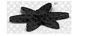
- the fluid vortex forming element (122) includes a filler with one portion protruding, and can be formed into various shapes (e.g., oval, star, cross, etc.) capable of generating a vortex by friction with a buffer, and the shape is not limited to a specific shape.
- the fluid vortex forming element (122) has a size of 5 mm in width, 1 mm in length, and 0.5 mm in height, and can be formed by mixing iron oxide (Fe 3 O 4 ) in a polymer material at a ratio of 10 wt% and then solidifying it.
- the fluid vortex forming element (122) generates a fluid vortex by rotating under the influence of a rotating magnetic field of an external force providing unit (130) in a reaction chamber (123), and non-specific binding can be removed through effective washing due to the vortex of the washing buffer.
- FIG. 7 is a drawing showing the non-specific binding removal performance of a fluid vortex forming element in one embodiment of the present invention.
- a fluid vortex forming element (122) can maximally remove nonspecific binding by generating a fluid vortex at 800 RPM for 20 minutes.
- FIG. 8 is a drawing specifically illustrating a process in which buffer exchange occurs in a microfluidic device of a microneedle automated analysis device according to one embodiment of the present invention.
- the reaction chamber (123) can sequentially introduce three types of buffers (buffer of detection antibody, washing buffer, and fluorescence labeling buffer) through the first inlet channel (Inlet 1) to the third inlet channel (Inlet 3).
- buffers buffer of detection antibody, washing buffer, and fluorescence labeling buffer
- the reaction chamber (123) may include a plurality of inlet channels (Inlet 1, ⁇ , Inlet n) and one outlet channel (Outlet).
- the reaction chamber (123) sequentially introduces buffers from the plurality of inlet channels, blocks the introduction of other buffers, performs organic exchange of buffers, removes nonspecific binding of the surface of the microneedle (112), and can fluorescently label a biomarker.
- reaction chamber (123) allows organic exchange of antibody detection buffer, washing buffer, and fluorescent labeling buffer, removes non-specific binding that may exist on the surface of the microneedle (112) through the fluid vortex generated by the fluid vortex forming element (122), and detects the biomarker by fluorescently labeling the biomarker.
- FIG. 9 is a diagram illustrating the biomarker quantitative analysis and reproducibility improvement performance of a microneedle automated analysis device according to one embodiment of the present invention.
- Figure 10 is a flow chart showing a method for manufacturing a microneedle automated analysis device according to one embodiment of the present invention.
- a microneedle automated analysis device (100) can be manufactured through a step (S910) of manufacturing a 3D printing mold for each component of a capture unit (110) and a reaction unit (120) using a 3D printer, a step (S920) of manufacturing by injecting a predetermined material into the 3D printing mold of each component, and a step (S930) of combining the manufactured components, respectively.
- the 3D printing molds can each be created according to a predetermined drawing.
- the microneedle (112) in the case of the microneedle (112), it can be produced using a conventional manufacturing method or digitized using a computer numerical controller in the shape of a bullet, and manufactured through a milling process with a bottom diameter of 0.25 mm and a height of 0.7 mm.
- a method of injecting a designated material to a predetermined height of the 3D printing mold and solidifying it to combine with the microneedle (112) or the fluid vortex forming element (122) can be used to manufacture it.
- the part processed in relief is directed toward the bottom surface.
- Figure 11 is a flow chart of a microneedle automated analysis method according to another embodiment of the present invention.
- the capture unit (110) can be temporarily attached to a part of the subject's body or immersed in a sample containing a biomarker to capture the biomarker (S110).
- FIG. 12 is a drawing illustrating an example of a process for detecting a biomarker by inserting a microneedle automated analysis device into a skin-mimicking phantom according to another embodiment of the present invention.
- FIG. 12 (a) is a drawing showing an example of inserting a microneedle automated analysis device (100) into a skin-mimicking phantom
- FIG. 12 (b) is a view from above of the microneedle automated analysis device (100) inserted into the skin-mimicking phantom
- FIG. 12 (c) is a view from below of the microneedle automated analysis device (100) inserted into the skin-mimicking phantom.
- the capture unit (110) can be inserted into a skin-mimicking phantom to detect a biomarker present in the skin-mimicking phantom.
- the microneedle automated analysis device (100) inserted into the skin-mimicking phantom is removed, it can be seen that no damage occurs to other areas except for the area where the microneedle automated analysis device (100) is inserted.
- reaction unit (120) can detect the captured biomarker using a fluid vortex (S120).
- the external force providing unit (130) can generate and provide an external force to generate a fluid vortex (S130).
- FIG. 14 is a diagram illustrating the biomarker quantitative analysis performance of a microneedle automated analysis device that shortens the biomarker detection time according to another embodiment of the present invention.
- the microneedle automated analysis device (100) can be used to quantitatively analyze biomarkers while reducing the detection time of biomarkers from 30 minutes to 10 minutes and 1 minute, and exhibits high reproducibility.
- FIG. 15 is a diagram illustrating the biomarker quantitative performance of a microneedle automated analysis device using an animal model according to another embodiment of the present invention.
- the fluid vortex forming element (122) when generating a vortex using acoustic operation, can generate acoustic streaming and fluid vortex through acoustic vibration as a translator.
- the translator can be in the form of being embedded in a piezoelectric substrate, and the external force providing unit (130) can provide surface acoustic waves (SAW) (e.g., Rayleigh waves) that generate a fluid vortex.
- SAW surface acoustic waves
- the fluid vortex forming element (122) can generate a fluid vortex by utilizing energy leakage at the Rayleigh wave angle.
- the fluid vortex forming element (122) when a vortex is generated using thermal operation, can generate a fluid vortex through density change and Marangoni flow.
- the external force providing unit (130) includes a small heater, and locally heats a part of the reaction unit (120) to form a temperature gradient, and as the temperature of the part of the locally heated reaction unit (120) increases, the surface tension decreases and a surface tension gradient can be generated.
- the fluid vortex forming element (122) can generate a fluid vortex by utilizing a surface tension gradient that promotes fluid flow along the boundary from a hot region to a cold region.
- the fluid vortex forming element (122) when generating a vortex using electrodynamic operation, may generate a fluid vortex by manipulating a fluid and particles through an electric field, and the reaction chamber (123) may include an electrolyte solution.
- the external force providing unit (130) may apply an alternating electric field to an electrode in contact with the electrolyte solution in the reaction chamber (123) or provide an electric field.
- the external force providing unit (130) applies an alternating current electric field to an electrode in contact with an electrolyte solution, and the fluid vortex forming element (122) induces a charge in a thin electric double layer near the electrode surface formed by the applied alternating current electric field, and can generate a fluid vortex by interaction between the induced charge and the tangential component of the alternating current electric field.
- the fluid vortex forming element (122) can change the velocity of the fluid depending on the frequency, and can generate fluid pumping and a fluid vortex depending on the electrode pattern design.
- the external force providing unit (130) provides an electric field
- the fluid vortex forming element (122) induces a charge on a surface that is polarizable by the electric field, and the induced charge attracts counter ions to form an induced electric double layer, and a fluid vortex can be generated through the interaction between the induced induced electric double layer and the applied electric field.
- the fluid vortex forming element (122) can perform manipulation of particles and fluids according to the design of the metal post array inside the microchannel.
- the microneedle automated analysis device (100) when generating a vortex using a curved and spiral fluid passage, does not include an external force providing unit (130), the reaction unit (120) has a curved or spiral microchannel, and the fluid vortex forming element (122) can generate a Dean vortex using centrifugal force.
- the fluid vortex forming element (122) receives centrifugal force when the fluid passes through the curved channel, and due to the no-slip condition, a pressure gradient is generated through the difference in fluid velocity that is higher at the center than at the boundary surface of the reaction chamber (123), and a secondary flow is induced through the pressure gradient, which can generate a fluid vortex.
- reaction unit (120) can efficiently perform particle manipulation or generate a fluid vortex by controlling the aspect ratio and radius of curvature of the reaction chamber (123).
- the microneedle automated analysis device (100) when generating a vortex by installing an obstacle, does not include an external force providing unit (130), and the fluid vortex forming element (122) is positioned as an obstacle within the reaction chamber (123) to generate a fluid vortex.
- the fluid vortex forming element (122) may generate a fluid vortex by causing a change in the height of the reaction chamber (123) to locally induce a pressure gradient and flow separation, or may be positioned in the path through which the fluid flows in the form of a micro-pillar to generate a fluid vortex, or may be positioned on the bottom of the reaction chamber (123) in a preset structure (e.g., a herringbone structure) to generate a transverse or spiral fluid vortex depending on the width and depth of the grooves of the structure.
- a preset structure e.g., a herringbone structure
- the analysis process can be simplified by automatically performing the reaction and change process of the buffer for the biomarker captured through the microneedle.
Landscapes
- Health & Medical Sciences (AREA)
- Life Sciences & Earth Sciences (AREA)
- Immunology (AREA)
- Engineering & Computer Science (AREA)
- Chemical & Material Sciences (AREA)
- Molecular Biology (AREA)
- Biomedical Technology (AREA)
- Hematology (AREA)
- Urology & Nephrology (AREA)
- Food Science & Technology (AREA)
- Biochemistry (AREA)
- Cell Biology (AREA)
- Biotechnology (AREA)
- Medicinal Chemistry (AREA)
- Physics & Mathematics (AREA)
- Analytical Chemistry (AREA)
- Microbiology (AREA)
- General Health & Medical Sciences (AREA)
- General Physics & Mathematics (AREA)
- Pathology (AREA)
- Chemical Kinetics & Catalysis (AREA)
- Oncology (AREA)
- Automatic Analysis And Handling Materials Therefor (AREA)
- Investigating Or Analysing Biological Materials (AREA)
Abstract
본 발명은 유체 와류 형성 소자를 이용한 마이크로니들 자동화 분석 장치에 관한 것이다. 본 발명의 실시예에 따르면, 피험자의 신체 일 부위에 일시적으로 부착되거나 또는 바이오마커가 포함된 샘플에 침지되어 바이오마커를 포획하는 포획부; 및 상기 포획된 바이오마커를 유체 와류를 이용하여 검출하는 반응부를 포함하고 상기 유체 와류를 발생시키기 위한 외력을 발생 및 제공하는 외력 제공부를 더 포함할 수 있다. 이와 같이 본 발명에 따르면 자동적으로 마이크로니들을 통해 포획된 바이오마커에 대해 버퍼의 반응 및 변경 과정을 자동으로 수행함으로써 분석 과정을 단순화시킬 수 있다. 또한, 바이오마커를 분석하면서 재현성과 민감성을 향상시키고, 분석 시간을 단축시킬 수 있다.
Description
본 발명은 유체 와류 형성 소자를 이용한 마이크로니들 자동화 분석 장치 및 그 방법에 관한 것으로서, 더욱 상세하게 설명하면 마이크로니들을 통해 추출된 바이오마커를 유체 와류 형성 소자를 이용하여 자동으로 검출하고 분석하는 유체 와류 형성 소자를 이용한 마이크로니들 자동화 분석 장치 및 그 방법에 관한 것이다.
마이크로니들 기반의 바이오마커를 검출하는 기술은 마이크로니들의 일 측면 또는 장치 외부에서 실험자에 의해 바이오마커와 항원(Antigen)과의 반응 및 버퍼 용액에 침지하여 교환 현상을 발생시킴으로써 바이오마커를 검출하는 것으로, 실험자의 숙련도에 따라 재현도가 달라진다는 단점이 있다.
또한, 진단을 하기 위해 분자 바이오마커 또는 생물학적 바이오마커를 검출하는 방법은 주로 환자로부터 체액 추출에 주로 의존하며, 추가적으로 처리하는 단계를 필요로 하여 약 하루정도의 시간이 소요된다.
따라서, 피험자의 신체에 존재하는 바이오마커를 보다 빠른 시간에 정밀하게 검출하는 기술이 필요한 실정이다.
본 발명의 배경이 되는 기술은 대한민국 등록특허 제10-1409610호(2014.06.20. 공고)에 기재되어 있다.
이와 같이 본 발명에 따르면, 마이크로니들을 통해 추출된 바이오마커를 유체 와류 형성 소자를 이용하여 자동으로 검출하고 분석하는 유체 와류 형성 소자를 이용한 마이크로니들 자동화 분석 장치 및 그 방법을 제공하기 위한 것이다.
이러한 기술적 과제를 이루기 위한 본 발명의 실시예에 따르면 유체 와류 형성 소자를 이용한 마이크로니들 자동화 분석 장치에 있어서, 피험자의 신체 일 부위에 일시적으로 부착되거나 또는 바이오마커가 포함된 샘플에 침지되어 바이오마커를 포획하는 포획부; 및 상기 포획된 바이오마커를 유체 와류를 이용하여 검출하는 반응부를 포함하고, 상기 유체 와류를 발생시키기 위한 외력을 발생 및 제공하는 외력 제공부를 더 포함할 수 있다.
상기 포획부는, 가스켓; 상기 피험자의 신체 일 부위에 부착되거나 또는 바이오마커가 포함된 샘플에 침지되어 바이오마커를 포획하고 상면에 상기 가스켓이 결합되는 마이크로니들; 및 상기 마이크로니들이 삽입되기 위한 공간이 형성되어 상기 가스켓과 결합된 마이크로니들이 삽입되는 서스펜션 레이어를 포함할 수 있다.
상기 반응부는, 반응 챔버; 상기 반응 챔버로 버퍼가 유입되는 복수의 유입 채널 및 반응 완료된 버퍼가 유출되는 유출 채널이 형성된 채널 레이어; 상기 반응 챔버 내에 삽입되어 상기 유체 와류를 생성하는 유체 와류 형성 소자; 및 상기 채널 레이어의 하면에 결합되는 유리를 포함할 수 있다.
상기 유체 와류 형성 소자는, 하면의 중심부에 일 부위가 돌출된 필러 구조가 형성되며, 상기 외력 제공부의 외력에 따라 회전 속도가 변할 수 있다.
상기 반응부는, 상기 반응 챔버에 항체 감지 버퍼, 워싱 버퍼 및 형광 라벨링 버퍼가 순차적으로 유입되고 다른 버퍼의 유입을 차단하며 버퍼의 유기적인 교환을 수행하고, 상기 마이크로니들 표면의 비특이적 결합을 제거하며, 상기 바이오마커에 형광 라벨링하여 바이오마커를 검출할 수 있다.
본 발명의 다른 실시예에 따르면 유체 와류 형성 소자를 이용한 마이크로니들 자동화 분석 방법에 있어서, 피험자의 신체 일 부위에 일시적으로 부착되거나 또는 바이오마커가 포함된 샘플에 침지되어 바이오마커를 포획하는 단계; 상기 유체 와류를 발생시키기 위한 외력을 발생 및 제공하는 단계; 및 상기 포획된 바이오마커를 유체 와류를 이용하여 검출하는 단계를 더 포함할 수 있다.
이와 같이 본 발명에 따르면, 자동적으로 마이크로니들을 통해 포획된 바이오마커에 대해 버퍼의 반응 및 변경 과정을 자동으로 수행함으로써 분석 과정을 단순화시킬 수 있다.
또한, 바이오마커를 분석하면서 재현성과 민감성을 향상시키고, 분석 시간을 단축시킬 수 있다.
도 1은 본 발명의 일 실시예에 따른 마이크로니들 자동화 분석 장치의 구조도이다.
도 2는 본 발명의 일 실시예에 따른 제조된 마이크로니들 자동화 분석 장치를 도시하는 도면이다.
도 3은 본 발명의 일 실시예에 따른 피험자에게서 바이오마커를 검출하고 분석하는 일 예를 도시하는 도면이다.
도 4는 본 발명의 일 실시예에 따른 유체 와류 형성 소자를 이용하여 비특이적 결합을 제거하는 일 예를 도시하는 도면이다.
도 5는 본 발명의 일 실시예에 따른 유체 와류 형성 소자를 도시하는 예시도이다.
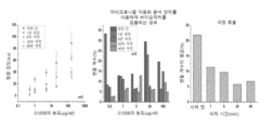
도 6은 본 발명의 일 실시예에 따른 유체 와류 형성 소자의 형상과 각 형상별 와류 생성 능력을 나타내는 도면이다.
도 7은 본 발명의 일 실시예에서 유체 와류 형성 소자의 비특이적 결합 제거 성능을 나타내는 도면이다.
도 8은 본 발명의 일 실시예에 따른 마이크로니들 자동화 분석 장치의 미세유체소자에서 버퍼 교환이 발생하는 과정을 구체적으로 도시한 도면이다.
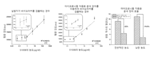
도 9는 본 발명의 일 실시예에 따른 마이크로니들 자동화 분석 장치의 바이오마커 정량 분석 및 재현성 향상 성능을 도시하는 도면이다.
도 10은 본 발명의 일 실시예에 따른 마이크로니들 자동화 분석 장치의 제조방법을 나타낸 순서도이다.
도 11은 본 발명의 다른 실시예에 따른 마이크로니들 자동화 분석 방법의 순서도이다.
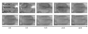
도 12는 본 발명의 다른 실시예에 따른 피부 모방 팬텀에 마이크로니들 자동화 분석 장치를 삽입하여 바이오마커를 검출하는 과정의 일 예를 도시하는 도면이다.
도 13은 본 발명의 다른 실시예에 따른 피부 모방 팬텀에서 마이크로니들 자동화 분석 장치의 바이오마커 정량 분석 및 재현성 향상 성능을 도시하는 도면이다.
도 14는 본 발명의 다른 실시예에 따른 바이오마커 검출 시간을 단축한 마이크로니들 자동화 분석 장치의 바이오마커 정량 분석 성능을 도시하는 도면이다.
도 15는 본 발명의 다른 실시예에 따른 동물 모델을 이용한 마이크로니들 자동화 분석 장치의 바이오마커 정량 성능을 도시하는 도면이다.
이하 첨부된 도면을 참조하여 본 발명에 따른 바람직한 실시예를 상세히 설명하기로 한다. 이 과정에서 도면에 도시된 선들의 두께나 구성요소의 크기 등은 설명의 명료성과 편의상 과장되게 도시되어 있을 수 있다.
명세서 전체에서, 어떤 부분이 어떤 구성요소를 "포함"한다고 할 때, 이는 특별히 반대되는 기재가 없는 한 다른 구성요소를 제외하는 것이 아니라 다른 구성요소를 더 포함할 수 있는 것을 의미한다.
또한 후술되는 용어들은 본 발명에서의 기능을 고려하여 정의된 용어들로서, 이는 사용자, 운용자의 의도 또는 관례에 따라 달라질 수 있다. 그러므로 이러한 용어들에 대한 정의는 본 명세서 전반에 걸친 내용을 토대로 내려져야 할 것이다.
후술하는 실시예에서 마이크로니들 자동화 분석 장치(100)는 유체 와류 형성 소자(Fluid vortex generating elements)로 자성 교반 소자(Magnetic stirrer tool, MST)를 사용하여 자력을 통해 생성된 와류를 이용하여 마이크로니들을 자동으로 분석하는 것으로 구체적인 예를 들어 설명한다. 그러나, 본 발명이 이로 제한되는 것은 아니며, 자기 작동, 음향 작동, 열 작동, 전기동역학 작동, 곡선 및 나선형 유체 통로, 장애물 설치 등과 같은 방법을 통해 유체 와류를 생성할 수 있다.
도 1은 본 발명의 일 실시예에 따른 마이크로니들 자동화 분석 장치의 구조도이고, 도 2는 본 발명의 일 실시예에 따른 제조된 마이크로니들 자동화 분석 장치를 도시하는 도면이다.
도 1 및 도 2에 도시된 바와 같이, 마이크로니들 자동화 분석 장치(100)는 포획부(110), 반응부(120) 및 외력 제공부(130)를 포함할 수 있다.
먼저, 포획부(110)는 피험자의 신체 일 부위에 일시적으로 부착되거나 또는 바이오마커가 포함된 샘플에 침지되어 바이오마커를 포획할 수 있다.
구체적으로, 포획부(110)는 피험자의 신체 일 부위에 부착되거나 또는 바이오마커가 포함된 샘플에 침지되어 바이오마커를 포획하는 마이크로니들(112)을 포함하고, 마이크로니들(112)의 상면에 가스켓(Gasket)(111)이 결합되고, 가스켓(111)과 결합된 마이크로니들(112)이 서스펜션 레이어(Suspension layer)(113)에 삽입될 수 있다.
또한, 가스켓(111)은 고분자(Polydimethylsiloxane, PDMS), 고무, 실리콘, 메탈, 테플론(Polytetrafluoroethylene, PTFE), 세라믹 등과 같은 다양한 물질로 제작되고, 가스켓(111)은 마이크로니들(112)의 상면에 결합할 수 있다. 이때, 가스켓(111)은 마이크로니들(112)을 서스펜션 레이어(113)에 삽입하여 장착할 때 공차의 발생을 방지하고, 샘플이 새지 않도록 보조할 수 있다.
다음으로, 마이크로니들(112)은 예를 들어, 금속, 고분자, 실리콘, 자연유래 성분, 약물 등과 같은 다양한 물질로 구성되어 피험자의 신체 일 부위에 부착되거나 또는 바이오마커가 포함된 샘플에 침지되어 바이오마커를 포획할 수 있다.
일 실시예에 따르면, 마이크로니들(112)은 피험자로부터 피부 간질액 또는 샘플에 포함된 바이오마커를 포획할 수 있다. 일 예로, 바이오마커는 흑색종 바이오마커인 S100B일 수 있다.
도 3은 본 발명의 일 실시예에 따른 피험자에게서 바이오마커를 검출하고 분석하는 일 예를 도시하는 도면이다.
도 3에 도시된 바와 같이, 마이크로니들(112)의 표면에는 바이오마커와 반응하는 1차 항체(Primary antibody)가 부착될 수 있다. 이때, 1차 항체는 피부 간질액 또는 샘플에 포함된 바이오마커와 항원-항체 반응을 통해 바이오마커를 포획할 수 있다.
구체적으로, 마이크로니들(112)은 10mTorr, 10sccm, 100W(O2 gas) 조건에서 기 설정된 시간(예를 들어, 10분)동안 플라즈마 처리하여 마이크로니들(112)의 표면이 음전하가 띄도록 처리한 후 양전하를 띄는 물질에 침지시켜 마이크로니들(112)의 표면이 양전하를 띄도록 코팅할 수 있다.
또한, 양전하를 띄는 마이크로니들(112)을 1차 항체가 있는 용액에 침지하여 전기적으로 마이크로니들(112)의 표면에 1차 항체를 부착시킬 수 있다.
다음으로, 마이크로니들(112)은 피험자의 일 부위에 부착되어 피부 간질액(Interstitial fluid, ISF)에 포함된 바이오마커를 포획할 수 있다.
또한, 마이크로니들(112)은 0.05㎍/㎖ 내지 160㎍/㎖ 농도의 바이오마커를 포함하는 샘플에 침지되어 바이오마커를 포획할 수 있다.
다음으로, 서스펜션 레이어(113)는 마이크로니들(112)이 삽입되기 위한 공간이 형성되어 가스켓(111)과 결합된 마이크로니들(112)이 삽입될 수 있다.
부연하자면, 바이오마커를 포획한 후 마이크로니들(112)의 상면에 가스켓(111)을 부착하고, 가스켓(111)이 부착된 마이크로니들(112)은 서스펜션 레이어(113)에 결합될 수 있다. 여기서, 서스펜션 레이어(113)는 마이크로니들(112)이 삽입되기 위한 공간이 형성되어 가스켓(111)과 결합된 마이크로니들(112)이 삽입될 수 있다.
또한, 서스펜션 레이어(113)의 일 하면에는 반응부(120)가 결합될 수 있다.
다음으로, 반응부(120)는 포획된 바이오마커를 유체 와류를 통해 적어도 한 종류의 버퍼(Buffer)와 반응시켜 바이오마커를 검출할 수 있다.
구체적으로, 반응부(120)는 반응 챔버(Reaction chamber)(123)와 반응 챔버(123)로 버퍼가 유입되는 복수의 유입 채널(Inlet) 및 반응 완료된 버퍼가 유출되는 유출 채널(Outlet)이 형성된 채널 레이어(Channel layer)(121)로 이루어지고, 반응 챔버(123) 내에는 유체 와류 형성 소자(예를 들어, 자성 교반 소자)(122)가 삽입될 수 있으며, 채널 레이어(121)의 하면에 유리(Slide glass)(124)가 결합될 수 있다. 이때, 반응 챔버(123)는 정중앙에 서스펜션 레이어(113)에 결합된 마이크로니들(112)이 위치하도록 형성될 수 있다.
또한, 반응 챔버(123)는 다양한 버퍼가 순차적으로 유입되고 다른 버퍼의 유입을 차단하며 버퍼의 유기적인 교환을 수행할 수 있다. 이때, 버퍼의 유기적인 교환은 후술하는 실시예에서 보다 구체적으로 설명한다.
또한, 유체 와류 형성 소자(122)는 바이오마커와 버퍼의 반응을 발생시키는 유체 와류를 생성할 수 있다. 이때, 유체 와류 형성 소자(122)의 하면의 중심부에는 필러(Pillar) 구조가 형성될 수 있다. 이에 따라 유리(124)와의 접촉면을 감소하여 마찰력을 최소화하고, 자력에 의해 유체 와류 형성 소자(122)가 빠르게 회전하도록 하여 유체 와류의 형성을 도모할 수 있다.
또한, 반응 챔버(123)는 생성된 유체 와류를 이용하여 바이오마커를 검출할 수 있다.
부연하자면, 반응 챔버(123)는 제1 유입 채널로 2차 항체를 포함하는 버퍼가 유입되며 유체 와류 형성 소자(122)에 의해 생성된 유체 와류를 이용하여 항원-항체 반응을 통해 바이오마커와 2차 항체가 결합할 수 있다.
또한, 반응 챔버(123)는 제2 유입 채널로 워싱 버퍼(Washing buffer)가 유입되며 유체 와류 형성 소자(122)에 의해 생성된 유체 와류를 통해 마이크로니들(112) 표면의 비특이적 결합(Non-specific binding, NSB)을 제거할 수 있다. 이때, 반응 챔버(123)는 유체 와류를 이용하여 마이크로니들(112) 표면의 1차 항체, 바이오마커 및 2차 항체가 순차적으로 결합한 구조가 아닌 결합을 제거할 수 있다.
또한, 반응 챔버(123)는 제3 유입 채널로 형광 물질이 포함된 버퍼(예를 들어, Streptavidin conjugated Texas red buffer)가 유입되며 유체 와류 형성 소자(122)에 의해 생성된 유체 와류를 이용하여 2차 항체를 표적으로 하는 형광 물질을 마이크로니들(112)에 부착시킬 수 있다.
형광 물질이 부착된 후, 반응 챔버(123)는 다시 한 번 제2 유입 채널로 워싱 버퍼가 유입되어 마이크로니들(112) 표면의 비특이적 결합을 제거할 수 있다. 이때, 반응 챔버(123)는 마이크로니들(112) 표면의 1차 항체, 바이오마커, 2차 항체 및 형광 물질이 순차적으로 결합한 구조가 아닌 결합을 제거할 수 있다.
일 실시예에 따르면, 반응 챔버(123)는 서스펜션 레이어(113)에 결합된 마이크로니들(112)의 위치와 상응하는 위치에 형성될 수 있다.
즉, 마이크로니들 자동화 분석 장치(100)는 포획된 바이오마커를 2차 항체(Secondary antibody)와 항원-항체 반응을 통해 부착시키고, 2차 항체를 표적으로 하여 형광을 발현하는 나노라벨(Nanolabel)과 부착시킬 수 있다.
이로 인해, 마이크로니들 자동화 분석 장치(100)는 형광 신호 측정을 통해 바이오마커의 정량 분석이 가능하다.
다음으로, 외력 제공부(130)는 유체 와류를 발생시키기 위한 외력을 발생 및 제공할 수 있다.
구체적으로, 외력 제공부(130)는 회전 자석(Rotating magnetic)을 이용하여 유체 와류를 발생시키는 회전 자기장을 제공할 수 있다.
여기서, 회전 자석은 기 지정된 방향(예를 들어, 반시계 방향 또는 시계 방향)으로 회전하면서 유체 와류 형성 소자(122)의 회전을 유도하여 유체 와류 발생을 보조할 수 있다. 이때, 유체 와류 형성 소자(122)의 회전 속도는 회전 자석의 회전 속도에 따라 변할 수 있다.
도 4는 본 발명의 일 실시예에 따른 유체 와류 형성 소자를 이용하여 비특이적 결합을 제거하는 일 예를 도시하는 도면이고, 도 5는 본 발명의 일 실시예에 따른 유체 와류 형성 소자를 도시하는 예시도이며, 도 6은 본 발명의 일 실시예에 따른 유체 와류 형성 소자의 형상과 각 형상별 와류 생성 능력을 나타내는 도면이다.
도 4에 도시된 바와 같이, 면역 분석 과정에서 존재하는 비특이적 결합은 유체 와류 형성 소자(122) 및 외력 제공부(130)에 의해 생성된 유체 와류를 이용하여 워싱 버퍼(Washing buffer)와 반응하여 제거될 수 있다.
도 5에 도시된 바와 같이, 유체 와류 형성 소자(122)는 일 부위가 돌출된 필러를 포함하는 것으로, 버퍼와의 마찰에 의해 와류를 생성 가능한 다양한 형상(예를 들어, 타원형, 별모양, 십자가형 등)으로 형성될 수 있으며, 그 형상이 특정 형상으로 제한되는 것은 아니다. 이때, 유체 와류 형성 소자(122)는 가로 5㎜, 세로 1㎜ 및 높이 0.5㎜의 크기를 가지며, 고분자 물질에 산화철(Fe3O4)을 10wt% 비율로 섞어 굳힌 것일 수 있다.
도 6에 도시된 바와 같이, 다양한 형상의 유체 와류 형성 소자(122)의 와류 생성 능력을 비교하면, 약 8초에 각 버퍼에 충분한 유체 와류를 생성함을 알 수 있다.
또한, 유체 와류 형성 소자(122)가 저항을 더 많이 일으키는 형상일수록 더 적은 시간에 더 많은 와류를 생성하여 더 적은 시간에서 마이크로니들(112)의 비특이적 결합을 효율적으로 제거함을 알 수 있다.
일 실시예에 따르면, 유체 와류 형성 소자(122)는 반응 챔버(123)에서 외력 제공부(130)의 회전 자기장의 영향에 따라 회전함으로써 유체 와류를 생성하고, 워싱 버퍼의 와류로 인한 효과적인 워싱을 통해 비특이적 결합을 제거할 수 있다.
도 7은 본 발명의 일 실시예에서 유체 와류 형성 소자의 비특이적 결합 제거 성능을 나타내는 도면이다.
도 7을 참조하면, 유체 와류 형성 소자(122)의 회전에 의해 생성된 워싱 버퍼의 와류로 워싱을 진행한 결과 비특이적 결합을 효과적으로 제거하여 형광 신호 값의 감소와 함께 편차가 크게 감소하면서 재현성이 향상되는 것을 알 수 있다. 또한, 유체 와류 형성 소자(122)는 800RPM으로 20분동안 유체 와류를 생성하는 것이 비특이적 결합을 최대로 제거할 수 있다.
도 8은 본 발명의 일 실시예에 따른 마이크로니들 자동화 분석 장치의 미세유체소자에서 버퍼 교환이 발생하는 과정을 구체적으로 도시한 도면이다.
도 8에 도시된 바와 같이, 반응 챔버(123)는 3가지 종류의 버퍼(항체 감지 버퍼(Buffer of detection antibody), 워싱 버퍼 및 형광 라벨링 버퍼(Fluorescence labeling buffer))가 제1 유입 채널(Inlet 1) 내지 제3 유입 채널(Inlet 3)을 통해 순차적으로 유입될 수 있다.
또한, 반응 챔버(123)는 복수의 유입 채널(Inlet 1, 쪋, Inlet n)과 1개의 유출 채널(Outlet)을 포함할 수 있다. 여기서, 반응 챔버(123)는 복수의 유입 채널에서 버퍼가 순차적으로 유입되고 다른 버퍼의 유입을 차단하며 버퍼의 유기적인 교환을 수행하고, 마이크로니들(112) 표면의 비특이적 결합을 제거하며, 바이오마커에 형광 라벨링할 수 있다.
다시 말해, 반응 챔버(123)는 항체 감지 버퍼, 워싱 버퍼 및 형광 라벨링 버퍼의 유기적인 교환이 일어나고, 유체 와류 형성 소자(122)에 의해 생성된 유체 와류를 통해 마이크로니들(112) 표면에 존재할 수 있는 비특이적 결합을 제거하며, 바이오마커에 형광 라벨링하여 바이오마커를 검출할 수 있다.
도 9는 본 발명의 일 실시예에 따른 마이크로니들 자동화 분석 장치의 바이오마커 정량 분석 및 재현성 향상 성능을 도시하는 도면이다.
도 9를 참조하면, 마이크로니들 자동화 분석 장치(100)를 사용하지 않고 실험자가 복수의 버퍼를 반응시키고, 마이크로니들(112)을 버퍼에 침지시켜 바이오마커를 검출하는 경우(Conventional method)와 마이크로니들 자동화 분석 장치(100)를 이용하여 바이오마커를 검출하는 경우(Device application)를 비교하면, 마이크로니들 자동화 분석 장치(100)를 이용하여 바이오마커를 검출한 경우가 편차가 더 적으면서, 재현성이 약 52% 향상되었고, 더 낮은 바이오마커 농도 구간에서 74.5% 더 큰 폭의 재현성 향상을 확인하였다.
도 10은 본 발명의 일 실시예에 따른 마이크로니들 자동화 분석 장치의 제조방법을 나타낸 순서도이다.
도 10에 도시된 바와 같이, 3D 프린터기를 이용하여 포획부(110) 및 반응부(120)의 각 구성에 대한 3D 프린팅 몰드를 제작하는 단계(S910), 각 구성의 3D 프린팅 몰드에 기 지정된 물질을 주입하여 제조하는 단계(S920) 및 제조된 구성을 각각 결합하는 단계(S930)를 통해 마이크로니들 자동화 분석 장치(100)를 제조할 수 있다. 이때, 3D 프린팅 몰드는 기 지정된 도면에 따라 각각 생성할 수 있다.
여기서, 마이크로니들(112)의 경우 종래의 제작 방법을 이용하여 생성하거나 총알 모양으로 컴퓨터 수치제어기를 이용하여 수치화하여 바닥부분은 0.25㎜의 직경으로, 높이는 0.7㎜로 밀링 공정을 통해 제조할 수 있다.
이때, 서스펜션 레이어(113) 또는 반응 챔버(123)의 경우, 마이크로니들(112) 또는 유체 와류 형성 소자(122)와 결합하기 위해 3D 프린팅 몰드의 기 설정된 높이까지 기 지정된 물질을 주입하여 굳히는 방법을 이용하여 제조할 수 있다. 이때, 양각으로 처리된 부분을 바닥면으로 향하게 한다.
도 11은 본 발명의 다른 실시예에 따른 마이크로니들 자동화 분석 방법의 순서도이다.
도 11에 도시된 바와 같이, 포획부(110)는 피험자의 신체 일 부위에 일시적으로 부착되거나 또는 바이오마커가 포함된 샘플에 침지되어 바이오마커를 포획할 수 있다(S110).
도 12는 본 발명의 다른 실시예에 따른 피부 모방 팬텀에 마이크로니들 자동화 분석 장치를 삽입하여 바이오마커를 검출하는 과정의 일 예를 도시하는 도면이다.
도 12의 (a)는 피부 모방 팬텀에 마이크로니들 자동화 분석 장치(100)를 삽입하는 일 예를 도시하는 도면이고, 도 12의 (b)는 피부 모방 팬텀에 삽입된 마이크로니들 자동화 분석 장치(100)를 위에서 본 모습이며, 도 12의 (c)는 피부 모방 팬텀에 삽입된 마이크로니들 자동화 분석 장치(100)를 아래에서 본 모습이다.
도 12의 (a) 내지 (c)에 도시된 바와 같이, 포획부(110)는 피부 모방 팬텀에 삽입되어 피부 모방 팬텀 내 존재하는 바이오마커를 검출할 수 있다. 도 12의 (d)에 도시된 바와 같이, 피부 모방 팬텀에 삽입된 마이크로니들 자동화 분석 장치(100)를 제거하면 마이크로니들 자동화 분석 장치(100)가 삽입된 부분을 제외하고 다른 부위에 손상이 발생하지 않음을 알 수 있다.
이후, 반응부(120)는 포획된 바이오마커를 유체 와류를 이용하여 검출할 수 있다(S120).
이를 위해, 외력 제공부(130)는 유체 와류를 발생시키기 위한 외력을 발생 및 제공할 수 있다(S130).
각 단계가 수행하는 구체적인 내용은 도 1 내지 도 9를 참조하여 서술한 바와 같으므로 중복적인 설명은 생략한다.
도 13은 본 발명의 다른 실시예에 따른 피부 모방 팬텀에서 마이크로니들 자동화 분석 장치의 바이오마커 정량 분석 및 재현성 향상 성능을 도시하는 도면이다.
도 13에 도시된 바와 같이, 실험자가 마이크로니들 자동화 분석 장치(100)를 사용하지 않고 피부 모방 팬텀에 복수의 버퍼를 반응시키고 마이크로니들(112)을 버퍼에 침지시켜 바이오마커를 검출하는 경우(Conventional method)와 마이크로니들 자동화 분석 장치(100)를 이용하여 바이오마커를 검출하는 경우(Integrated system)을 비교하면 마이크로니들 자동화 분석 장치(100)를 이용하여 바이오마커를 검출한 경우가 편차가 더 적으면서, 더 낮은 검출한계를 보이는 것을 확인할 수 있다.
도 14는 본 발명의 다른 실시예에 따른 바이오마커 검출 시간을 단축한 마이크로니들 자동화 분석 장치의 바이오마커 정량 분석 성능을 도시하는 도면이다.
도 14에 도시된 바와 같이, 마이크로니들 자동화 분석 장치(100)는 바이오마커의 검출 시간을 30분에서 10분과 1분으로 감소시키면서 바이오마커의 정량 분석이 가능하고 높은 재현성을 보임을 알 수 있다.
도 15는 본 발명의 다른 실시예에 따른 동물 모델을 이용한 마이크로니들 자동화 분석 장치의 바이오마커 정량 성능을 도시하는 도면이다.
도 15에 도시된 바와 같이, 피부 흑색종을 갖고 있는 동물 모델에 마이크로니들 자동화 분석 장치(100)를 이용하여 바이오마커를 검출한 경우 도 14에 도시된 바와 같이 30분 이내로 바이오마커 검출이 가능하고, 1분의 검출 시간으로도 향상된 재현성으로 바이오마커 검출 가능한 것을 알 수 있다.
본 발명의 다른 실시예에 따르면 음향 작동을 이용하여 와류를 발생시키는 경우, 유체 와류 형성 소자(122)는 변환기(Translator)로 음파 진동을 통해 음향 스트리밍 및 유체 와류를 생성할 수 있다. 이때, 변환기는 압전 기판에 끼어있는 형태일 수 있고, 외력 제공부(130)는 유체 와류를 발생시키는 표면 음향파(Surface acoustic waves, SAW)(예를 들어, 레일리파(Rayleigh waves)를 제공할 수 있다.
여기서, 유체 와류 형성 소자(122)는 레일리파 각도로 에너지가 누출됨을 이용하여 유체 와류를 생성할 수 있다.
본 발명의 다른 실시예에 따르면 열 작동을 이용하여 와류를 발생시키는 경우, 유체 와류 형성 소자(122)는 밀도 변화와 마랑고니 흐름(Marangoni flow)을 통해 유체 와류를 생성할 수 있다. 이때, 외력 제공부(130)는 소형 히터를 포함하고, 반응부(120)의 일 부분을 국부적으로 가열하여 온도 구배를 형성하고 국부적으로 가열된 반응부(120)의 일 부분에 대한 온도가 증가하면서 표면장력이 감소되며 표면장력 구배를 발생할 수 있다.
여기서, 유체 와류 형성 소자(122)는 뜨거운 영역에서 차가운 영역으로 경계면을 따라 유체 흐름을 촉진시키는 표면장력 구배를 이용하여 유체 와류를 생성할 수 있다.
본 발명의 다른 실시예에 따르면 전기동역학 작동을 이용하여 와류를 발생시키는 경우, 유체 와류 형성 소자(122)는 전기장을 통해 유체와 입자를 조작하여 유체 와류를 생성하고, 반응 챔버(123)는 전해질 용액을 포함할 수 있다. 이때, 외력 제공부(130)는 반응 챔버(123) 내 전해질 용액과 접촉하는 전극에 교류 전기장을 인가하거나 전기장을 제공할 수 있다.
여기서, 교류 전기 삼투를 통해 와류를 발생시키는 경우, 외력 제공부(130)는 전해질 용액과 접촉하는 전극에 교류 전기장을 인가하고, 유체 와류 형성 소자(122)는 인가된 교류 전기장에 의해 형성된 전극 표면 근처의 얇은 전기 이중층에 전하를 유도하며 유도된 전하와 교류 전기장의 접선 방향 성분 사이의 상호작용으로 유체 와류를 생성할 수 있다. 이때, 유체 와류 형성 소자(122)는 주파수에 따라 유체의 속도가 달라지고 전극 패턴 설계에 따라 유체 펌핑 및 유체 와류를 생성할 수 있다.
또한, 유도 전하 전기 삼투를 통해 와류를 발생시키는 경우, 외력 제공부(130)는 전기장을 제공하고, 유체 와류 형성 소자(122)는 전기장에 의해 분극 가능한 표면에 전하를 유도하고 유도된 전하가 반대 이온을 끌어당겨 유도 전기 이중층을 형성하며 유도된 유도 전기 이중층과 인가된 전기장 사이의 상호작용을 통해 유체 와류를 생성할 수 있다.
이때, 유체 와류 형성 소자(122)는 미세 채널 내부의 금속 포스트 배열의 설계에 따라 입자 및 유체의 조작을 수행할 수 있다.
본 발명의 다른 실시예에 따르면 곡선 및 나선형 유체 통로를 이용하여 와류를 발생시키는 경우, 마이크로니들 자동화 분석 장치(100)는 외력 제공부(130)를 포함하지 않고, 반응부(120)는 곡선형 또는 나선형의 미세 채널을 갖으며, 유체 와류 형성 소자(122)는 원심력을 이용하여 딘(Dean) 와류를 생성할 수 있다.
이때, 유체 와류 형성 소자(122)는 유체가 곡선 채널을 통과할 때 원심력을 받고 미끄러짐이 없는 상태(No-slip condition)로 인하여 반응 챔버(123)의 경계면보다 중앙에서 높은 유체 속도의 차이를 통해 압력 구배가 생성되고, 압력 구배를 통해 2차 흐름이 유도되어 유체 와류를 생성할 수 있다.
또한, 반응부(120)는 반응 챔버(123)의 종횡비와 곡률 반경 등을 조절하여 효율적으로 입자 조작을 수행하거나 또는 유체 와류를 생성할 수 있다.
본 발명의 다른 실시예에 따르면 장애물 설치를 통해 와류를 발생시키는 경우, 마이크로니들 자동화 분석 장치(100)는 외력 제공부(130)를 포함하지 않고, 유체 와류 형성 소자(122)는 반응 챔버(123) 내에 장애물로 위치하여 유체 와류를 생성할 수 있다.
이때, 유체 와류 형성 소자(122)는 반응 챔버(123)의 높낮이에 변화를 발생시켜 국부적으로 압력 구배와 흐름 분리를 유도하여 유체 와류를 생성하거나 마이크로 필러 형태로 유체가 흐르는 경로에 위치하여 유체 와류를 생성하거나 기 설정된 구조(예를 들어, 헤링본 구조)로 반응 챔버(123)의 바닥에 위치하여 구조의 홈의 폭, 깊이 등에 따라 횡방향 또는 나선형 방향의 유체 와류를 생성할 수 있다.
본 발명의 실시예에 따르면, 자동적으로 마이크로니들을 통해 포획된 바이오마커에 대해 버퍼의 반응 및 변경 과정을 자동으로 수행함으로써 분석 과정을 단순화시킬 수 있다.
또한, 바이오마커를 분석하면서 재현성을 향상시키고, 분석 시간을 단축시킬 수 있다.
본 발명은 도면에 도시된 실시예를 참고로 하여 설명되었으나 이는 예시적인 것에 불과하며, 당해 기술이 속하는 분야에서 통상의 지식을 가진 자라면 이로부터 다양한 변형 및 균등한 타 실시예가 가능하다는 점을 이해할 것이다. 따라서 본 발명의 진정한 기술적 보호범위는 아래의 특허청구범위의 기술적 사상에 의하여 정해져야 할 것이다.
Claims (9)
- 유체 와류 형성 소자를 이용한 마이크로니들 자동화 분석 장치에 있어서,피험자의 신체 일 부위에 일시적으로 부착되거나 또는 바이오마커가 포함된 샘플에 침지되어 바이오마커를 포획하는 포획부; 및상기 포획된 바이오마커를 유체 와류를 이용하여 검출하는 반응부를 포함하는 마이크로니들 자동화 분석 장치.
- 제 1 항에 있어서,상기 유체 와류를 발생시키기 위한 외력을 발생 및 제공하는 외력 제공부를 더 포함하는 마이크로니들 자동화 분석 장치.
- 제 1 항에 있어서,상기 포획부는,가스켓;상기 피험자의 신체 일 부위에 부착되거나 또는 바이오마커가 포함된 샘플에 침지되어 바이오마커를 포획하고 상면에 상기 가스켓이 결합되는 마이크로니들; 및상기 마이크로니들이 삽입되기 위한 공간이 형성되어 상기 가스켓과 결합된 마이크로니들이 삽입되는 서스펜션 레이어를 포함하는 마이크로니들 자동화 분석 장치.
- 제 1 항에 있어서,상기 반응부는,반응 챔버;상기 반응 챔버로 버퍼가 유입되는 복수의 유입 채널 및 반응 완료된 버퍼가 유출되는 유출 채널이 형성된 채널 레이어;상기 반응 챔버 내에 삽입되어 상기 유체 와류를 생성하는 유체 와류 형성 소자; 및상기 채널 레이어의 하면에 결합되는 유리를 포함하는 유체 와류 형성 소자를 이용한 마이크로니들 자동화 분석 장치.
- 제 4 항에 있어서,상기 유체 와류 형성 소자는,하면의 중심부에 일 부위가 돌출된 필러 구조가 형성되며, 상기 외력 제공부의 외력에 따라 회전 속도가 변하는 유체 와류 형성 소자를 이용한 마이크로니들 자동화 분석 장치.
- 제 4 항에 있어서,상기 반응부는,상기 반응 챔버에 항체 감지 버퍼, 워싱 버퍼 및 형광 라벨링 버퍼가 순차적으로 유입되고 다른 버퍼의 유입을 차단하며 버퍼의 유기적인 교환을 수행하고, 상기 마이크로니들 표면의 비특이적 결합을 제거하며, 상기 바이오마커에 형광 라벨링하는 마이크로니들 자동화 분석 장치.
- 피험자의 신체 일 부위에 일시적으로 부착되거나 또는 바이오마커가 포함된 샘플에 침지되어 바이오마커를 포획하는 단계; 및상기 포획된 바이오마커를 유체 와류를 이용하여 검출하는 단계를 포함하는 마이크로니들 자동화 분석 방법.
- 제 7 항에 있어서,상기 유체 와류를 발생시키기 위한 외력을 발생 및 제공하는 단계를 더 포함하는 마이크로니들 자동화 분석 방법.
- 제 7 항에 있어서,상기 검출하는 단계는,상기 반응 챔버에 항체 감지 버퍼, 워싱 버퍼 및 형광 라벨링 버퍼가 순차적으로 유입되고 다른 버퍼의 유입을 차단하며 버퍼의 유기적인 교환을 수행하고, 상기 마이크로니들 표면의 비특이적 결합을 제거하며, 상기 바이오마커에 형광 라벨링하는 마이크로니들 자동화 분석 방법.
Applications Claiming Priority (2)
| Application Number | Priority Date | Filing Date | Title |
|---|---|---|---|
| KR10-2023-0153427 | 2023-11-08 | ||
| KR1020230153427A KR102856481B1 (ko) | 2023-11-08 | 2023-11-08 | 자성 교반 소자를 이용한 마이크로니들 자동화 분석 장치 및 그 방법 |
Publications (1)
| Publication Number | Publication Date |
|---|---|
| WO2025100735A1 true WO2025100735A1 (ko) | 2025-05-15 |
Family
ID=95695554
Family Applications (1)
| Application Number | Title | Priority Date | Filing Date |
|---|---|---|---|
| PCT/KR2024/014686 Pending WO2025100735A1 (ko) | 2023-11-08 | 2024-09-27 | 유체 와류 형성 소자를 이용한 마이크로니들 자동화 분석 장치 및 그 방법 |
Country Status (2)
| Country | Link |
|---|---|
| KR (1) | KR102856481B1 (ko) |
| WO (1) | WO2025100735A1 (ko) |
Citations (6)
| Publication number | Priority date | Publication date | Assignee | Title |
|---|---|---|---|---|
| JP2010516337A (ja) * | 2007-01-22 | 2010-05-20 | コリウム インターナショナル, インコーポレイテッド | マイクロニードルアレイ用アプリケータ |
| KR101409610B1 (ko) | 2010-07-13 | 2014-06-20 | (주)아모레퍼시픽 | 피부 진단 방법 및 키트 |
| KR20190044992A (ko) * | 2017-10-23 | 2019-05-02 | 서울대학교산학협력단 | 마이크로채널 및 자성체를 포함하는 표적물질 검출용 키트 |
| KR20210079957A (ko) * | 2019-12-20 | 2021-06-30 | 한국전자기술연구원 | 자성입자 기반의 면역 진단 기기 |
| KR20220038832A (ko) * | 2012-12-14 | 2022-03-29 | 민데라 코포레이션 | 바이오마커의 검출 및 취득을 위한 방법 및 디바이스 |
| KR20220107986A (ko) * | 2021-01-26 | 2022-08-02 | 단국대학교 천안캠퍼스 산학협력단 | 진단 및 분석을 위한 마이크로니들 기반 통합 액체생검 마이크로 시스템 |
-
2023
- 2023-11-08 KR KR1020230153427A patent/KR102856481B1/ko active Active
-
2024
- 2024-09-27 WO PCT/KR2024/014686 patent/WO2025100735A1/ko active Pending
Patent Citations (6)
| Publication number | Priority date | Publication date | Assignee | Title |
|---|---|---|---|---|
| JP2010516337A (ja) * | 2007-01-22 | 2010-05-20 | コリウム インターナショナル, インコーポレイテッド | マイクロニードルアレイ用アプリケータ |
| KR101409610B1 (ko) | 2010-07-13 | 2014-06-20 | (주)아모레퍼시픽 | 피부 진단 방법 및 키트 |
| KR20220038832A (ko) * | 2012-12-14 | 2022-03-29 | 민데라 코포레이션 | 바이오마커의 검출 및 취득을 위한 방법 및 디바이스 |
| KR20190044992A (ko) * | 2017-10-23 | 2019-05-02 | 서울대학교산학협력단 | 마이크로채널 및 자성체를 포함하는 표적물질 검출용 키트 |
| KR20210079957A (ko) * | 2019-12-20 | 2021-06-30 | 한국전자기술연구원 | 자성입자 기반의 면역 진단 기기 |
| KR20220107986A (ko) * | 2021-01-26 | 2022-08-02 | 단국대학교 천안캠퍼스 산학협력단 | 진단 및 분석을 위한 마이크로니들 기반 통합 액체생검 마이크로 시스템 |
Also Published As
| Publication number | Publication date |
|---|---|
| KR20250067371A (ko) | 2025-05-15 |
| KR102856481B1 (ko) | 2025-09-09 |
Similar Documents
| Publication | Publication Date | Title |
|---|---|---|
| US7686934B2 (en) | Three dimensional dielectrophoretic separator and methods of use | |
| JP4093740B2 (ja) | 微粒子分別マイクロチップと微粒子分別装置 | |
| JP4470310B2 (ja) | 誘電泳動力を用いた物質の分離方法 | |
| EP1614477A1 (en) | Method for separating substances using dielectrophoretic forces | |
| Shamloo et al. | Cancer cell enrichment on a centrifugal microfluidic platform using hydrodynamic and magnetophoretic techniques | |
| EP1400600A1 (en) | Integrated device for biological analyses | |
| JP2004532968A (ja) | 細胞亜集団分析のためのシステムおよび方法 | |
| Ko et al. | Microchip‐based multiplex electro‐immunosensing system for the detection of cancer biomarkers | |
| WO2016043402A1 (ko) | 교차전극 바이오센서 | |
| KR970707442A (ko) | 분할된 마이크로일렉트로닉 디바이스 어레이(a partitioned microelectronic device array) | |
| WO2011112023A2 (ko) | 혈구 분리 칩 | |
| WO2011005050A2 (ko) | 다기능 미세유체 유동 제어 장치 및 다기능 미세유체 유동 제어 방법 | |
| TWI635907B (zh) | 用於偵測生物標記的系統及方法 | |
| EP2367633A1 (en) | Assay device and method for performing biological assays | |
| CN106399091A (zh) | 基于旋转电场诱导的感应电荷电渗的细胞捕捉芯片 | |
| WO2008122241A1 (en) | Rapid protein analyses and the device thereof | |
| WO2011062407A2 (ko) | 분석물질의 검출 방법 및 장치 | |
| Lee et al. | Low-electric-potential-assisted diffusiophoresis for continuous separation of nanoparticles on a chip | |
| JP2005140333A (ja) | 静電封止デバイス及びその使用方法 | |
| Bu et al. | Continuous-flow label-free size fractionation of extracellular vesicles through electrothermal fluid rolls and dielectrophoresis synergistically integrated in a microfluidic device | |
| WO2025100735A1 (ko) | 유체 와류 형성 소자를 이용한 마이크로니들 자동화 분석 장치 및 그 방법 | |
| WO2015137691A1 (ko) | 테일러 괴틀러 와류를 이용한 마이크로 믹서 및 그 제작방법 | |
| CN110087749B (zh) | 微流体过滤装置和捕获通孔中物体的方法 | |
| Van Anh et al. | Development of a PMMA electrochemical microfluidic device for carcinoembryonic antigen detection | |
| WO2018143523A1 (ko) | 세포 임피던스 분광학 측정 장치 및 측정 방법 |
Legal Events
| Date | Code | Title | Description |
|---|---|---|---|
| 121 | Ep: the epo has been informed by wipo that ep was designated in this application |
Ref document number: 24888930 Country of ref document: EP Kind code of ref document: A1 |