WO2025100545A1 - 水素センサおよび水素検知システム - Google Patents
水素センサおよび水素検知システム Download PDFInfo
- Publication number
- WO2025100545A1 WO2025100545A1 PCT/JP2024/039976 JP2024039976W WO2025100545A1 WO 2025100545 A1 WO2025100545 A1 WO 2025100545A1 JP 2024039976 W JP2024039976 W JP 2024039976W WO 2025100545 A1 WO2025100545 A1 WO 2025100545A1
- Authority
- WO
- WIPO (PCT)
- Prior art keywords
- hydrogen
- sensor
- resistance value
- electrodes
- less
- Prior art date
- Legal status (The legal status is an assumption and is not a legal conclusion. Google has not performed a legal analysis and makes no representation as to the accuracy of the status listed.)
- Pending
Links
Images
Classifications
-
- G—PHYSICS
- G01—MEASURING; TESTING
- G01N—INVESTIGATING OR ANALYSING MATERIALS BY DETERMINING THEIR CHEMICAL OR PHYSICAL PROPERTIES
- G01N27/00—Investigating or analysing materials by the use of electric, electrochemical, or magnetic means
- G01N27/02—Investigating or analysing materials by the use of electric, electrochemical, or magnetic means by investigating impedance
- G01N27/04—Investigating or analysing materials by the use of electric, electrochemical, or magnetic means by investigating impedance by investigating resistance
- G01N27/12—Investigating or analysing materials by the use of electric, electrochemical, or magnetic means by investigating impedance by investigating resistance of a solid body in dependence upon absorption of a fluid; of a solid body in dependence upon reaction with a fluid, for detecting components in the fluid
Definitions
- This disclosure relates to hydrogen sensors and hydrogen detection systems.
- odorization which is used for city gas
- problems such as poisoning of fuel cells and deterioration of gas turbines arise. Therefore, safety measures that replace odorization are required. Therefore, to ensure safety, hydrogen sensors that detect hydrogen gas leaks have become extremely important.
- Conventional hydrogen sensors mainly use the catalytic combustion or semiconductor method.
- catalytic combustion hydrogen sensors a catalytic metal such as platinum or palladium is heated with a heater, and hydrogen gas that comes into contact with the catalyst is oxidized with oxygen in the air. The heat generated by the oxidation of this hydrogen gas is detected electrically as a change in the conductivity of the catalytic metal.
- semiconductor hydrogen sensors detect changes in the electrical properties of the sensitive film caused by the adsorption of hydrogen gas to the sensitive film, that is, changes in resistance value.
- these semiconductor hydrogen sensors are used in a heated state with a heater.
- conventional hydrogen sensors such as the catalytic combustion and semiconductor types pose a risk when used with hydrogen gas that requires explosion-proofing because they involve heating.
- Gasochromic hydrogen sensors have also been attracting attention.
- Gasochromic hydrogen sensors are equipped with a metal oxide such as tungsten trioxide, which changes color when hydrogen is absorbed, and a catalyst such as platinum, which dissociates hydrogen gas into hydrogen atoms, and detect hydrogen gas optically.
- Metal oxides such as tungsten trioxide also change their electrical properties when hydrogen is absorbed, so gasochromic hydrogen sensors can also detect hydrogen gas electrically.
- the resonant circuit when the resonant circuit receives a wireless signal at the resonant frequency, it induces an alternating current, which is stored and becomes the startup power, and data is transmitted.
- a wireless tag when hydrogen comes into contact with tungsten oxide, the tungsten oxide becomes conductive and the antenna coil is shorted, causing the inductance to fluctuate and the resonant frequency of the resonant circuit to fluctuate.
- the wireless tag determines the presence or absence of hydrogen based on the presence or absence of a reply from the wireless tag in response to the transmitted wireless signal.
- the wireless tag can only detect the presence or absence of hydrogen.
- This disclosure was made in consideration of the above situation, and its main purpose is to provide a hydrogen sensor that can manage hydrogen concentration.
- One embodiment of the present disclosure provides a hydrogen sensor including a substrate, a sensitive film disposed on a first surface of the substrate and containing a catalyst that dissociates hydrogen molecules and tungsten oxide, a pair of electrodes disposed on the first surface of the substrate in contact with the sensitive film, and an IC tag connected to the pair of electrodes, the IC tag including an IC chip, an antenna connected to the IC chip, and a pair of sensor terminals connected to the IC chip and respectively connected to the pair of electrodes, the IC chip being an open-short type that determines a high resistance state when the resistance value between the sensor terminals is equal to or greater than a first threshold resistance value, and determines a low resistance state when the resistance value between the sensor terminals is equal to or less than a second threshold resistance value that is smaller than the first threshold resistance value, and the hydrogen sensor provides a hydrogen sensor in which the resistance value between the sensor terminals when the hydrogen concentration is zero is equal to or greater than the first threshold resistance value, and the resistance value between the sensor terminals when the
- Another embodiment of the present disclosure provides a hydrogen detection system using the above-described hydrogen sensor.
- Another embodiment of the present disclosure provides a hydrogen pipeline using the hydrogen detection system described above.
- the hydrogen sensor disclosed herein has the effect of being able to manage hydrogen concentration.
- 1 is a schematic plan view illustrating a hydrogen sensor according to the present disclosure.
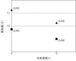
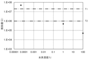
- 4 is a graph illustrating the relationship between hydrogen concentration and resistance value between sensor terminals in a hydrogen sensor according to the present disclosure.
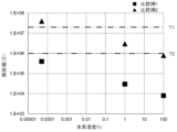
- 11 is a graph illustrating the relationship between hydrogen concentration and resistance value between sensor terminals in a hydrogen sensor not corresponding to an embodiment of the present disclosure.
- 1 is a schematic plan view illustrating a hydrogen sensor according to the present disclosure.
- 1 is a schematic plan view illustrating a hydrogen sensor according to the present disclosure.
- 1 is a schematic plan view illustrating a hydrogen sensor according to the present disclosure.
- 1 is a schematic plan view illustrating a hydrogen sensor according to the present disclosure.
- 1 is a schematic plan view illustrating a hydrogen sensor according to the present disclosure.
- 1 is a schematic plan view illustrating a hydrogen sensor according to the present disclosure.
- FIG. 1 is a schematic plan view illustrating a hydrogen sensor according to the present disclosure.
- 1 is a schematic plan view illustrating a hydrogen sensor according to the present disclosure.
- 1 is a schematic plan view illustrating a hydrogen sensor according to the present disclosure.
- 1 is a schematic plan view illustrating a hydrogen sensor according to the present disclosure.
- 1 is a schematic plan view illustrating a hydrogen sensor according to the present disclosure.
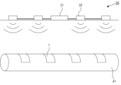
- FIG. 1 is a schematic diagram illustrating a hydrogen detection system in the present disclosure.
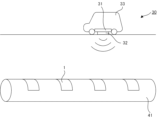
- FIG. 1 is a schematic diagram illustrating a hydrogen detection system in the present disclosure.
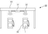
- FIG. 1 is a schematic diagram illustrating a hydrogen detection system in the present disclosure.
- 4 is a graph showing the relationship between hydrogen concentration and resistance value between sensor terminals in the hydrogen sensor of Example 1.
- 1 is a graph showing the relationship between hydrogen concentration and resistance between sensor terminals in the hydrogen sensors of Comparative Examples 1 and 2.
- the terms "on the face side" or “on the face” include both cases where another component is placed directly above or below a component so as to be in contact with the component, and cases where another component is placed above or below a component with another component in between, unless otherwise specified.
- sheet is used to include members also known as films and plates.
- the hydrogen sensor in the present disclosure is a hydrogen sensor that utilizes the fact that the resistance value of a sensitive film containing a catalyst and tungsten oxide decreases when the sensitive film reacts with hydrogen.
- the inventors of the present disclosure have conducted intensive research into a member for detecting the change in the resistance value of the sensitive film in such a hydrogen sensor, and have focused on an open short type IC chip.
- the open short type IC chip is an IC chip that detects the change in resistance value by determining that the resistance value between the terminals is in a high resistance state when the resistance value between the terminals is equal to or greater than a first threshold value, and that the resistance value between the terminals is equal to or less than a second threshold value.
- the resistance value between the terminals is equal to or greater than the first threshold value in an air atmosphere, and that the resistance value between the terminals is equal to or less than the second threshold value when the hydrogen concentration in the atmosphere increases. This makes it possible to detect hydrogen leakage.
- the first threshold value and the second threshold value are predetermined.
- the resistance value between the terminals becomes equal to or less than the second threshold value, or the resistance value between the terminals does not become equal to or less than the second threshold value even when the hydrogen concentration in the atmosphere increases.
- the resistance value between the terminals becomes equal to or less than the second threshold value, it is determined that hydrogen is leaking even in the air atmosphere.
- hydrogen leakage cannot be detected unless the resistance value between the terminals becomes equal to or less than the second threshold value.
- the inventors of the present disclosure further conducted studies and found that the resistance value between the terminals depending on the hydrogen concentration can be adjusted by appropriately designing the sensitive film and the pair of electrodes, such as the thickness of the sensitive film and the distance between the pair of electrodes, according to the first threshold value and the second threshold value of the open-short type IC chip. That is, when an open-short type IC chip is applied to the hydrogen sensor as described above, it was found that the resistance value between the terminals can be designed so that in the air atmosphere, the resistance value between the terminals becomes equal to or more than the first threshold value, and when the hydrogen concentration in the atmosphere increases, the resistance value between the terminals becomes equal to or less than the second threshold value.
- the present disclosure is based on such findings.
- open/short type IC chips are used to detect breaks in wiring or circuits.
- the hydrogen sensor disclosed herein is a hydrogen sensor including a substrate, a sensitive membrane disposed on a first surface of the substrate and containing a catalyst that dissociates hydrogen molecules and tungsten oxide, a pair of electrodes disposed on the first surface of the substrate in contact with the sensitive membrane, and an IC tag connected to the pair of electrodes, the IC tag including an IC chip, an antenna connected to the IC chip, and a pair of sensor terminals connected to the IC chip and respectively connected to the pair of electrodes, the IC chip being an open-short type that determines a high resistance state when the resistance value between the sensor terminals is equal to or greater than a first threshold resistance value, and determines a low resistance state when the resistance value between the sensor terminals is equal to or less than a second threshold resistance value that is smaller than the first threshold resistance value, the resistance value between the sensor terminals when the hydrogen concentration is zero is equal to or greater than the first threshold resistance value, and the resistance value between the sensor terminals when the hydrogen concentration is a set value is equal to or
- the hydrogen sensor 1 includes a substrate 2, a sensitive film 3 that is disposed on the first surface of the substrate 2 and contains a catalyst that dissociates hydrogen molecules and tungsten oxide, a pair of electrodes 4a, 4b that are disposed on the first surface of the substrate 2 in contact with the sensitive film 3, and an IC tag 5 connected to the pair of electrodes 4a, 4b.
- the pair of electrodes 4a, 4b are a pair of comb-shaped electrodes.
- the pair of electrodes 4a, 4b are alternately disposed at a distance d1 that allows detection of changes in the resistance value of the sensitive film 3.
- the IC tag 5 also includes a second substrate 21, an IC chip 22 that is disposed on the first surface of the second substrate 21, an antenna 23 that is disposed on the first surface of the second substrate 21 and connected to the IC chip 22, and a pair of sensor terminals 24a, 24b that are disposed on the first surface of the second substrate 21, connected to the IC chip 22, and connected to the pair of electrodes 4a, 4b, respectively.
- the IC chip 22 is an open-short type, and is determined to be in a high resistance state when the resistance value between the sensor terminals 24a, 24b connected to the IC chip 22 is equal to or greater than a first threshold resistance value, and is determined to be in a low resistance state when the resistance value between the sensor terminals 24a, 24b is equal to or less than a second threshold resistance value.
- the hydrogen sensor disclosed herein utilizes the phenomenon in which the resistance value of a sensitive film containing a catalyst and tungsten oxide decreases when the sensitive film reacts with hydrogen.
- the operating principle of the hydrogen sensor disclosed herein is explained below.
- Tungsten oxide (WO 3 ) has high electrical resistance. Therefore, in an atmosphere in which hydrogen is not present, the sensitive film 3 has high electrical resistance and is insulating. At this time, the pair of electrodes 4a, 4b are insulated and in a non-conductive state. Therefore, even if power is supplied from the RFID reader/writer to the IC tag 5, no current flows through the pair of electrodes 4a, 4b via the sensitive film 3.
- the IC chip 22 when the resistance value between the sensor terminals 24a, 24b is equal to or greater than the first threshold resistance value, the IC chip 22 is in a high resistance state, and the flag information is set to "0", for example. In the IC tag 5, the above information is transmitted to the RFID reader/writer via the antenna 23. In this case, it is determined that no hydrogen gas is leaking.
- the hydrogen molecules when hydrogen molecules come into contact with the catalyst, the hydrogen molecules are dissociated and adsorbed to generate hydrogen atoms. These hydrogen atoms reduce tungsten oxide (WO 3 ) to generate a non-stoichiometric compound (H x WO 3 (0 ⁇ x ⁇ 1)).
- the non-stoichiometric compound (H x WO 3 ) has a mixed valence state of W 5+ and W 6+ , and therefore has low electrical resistance. Therefore, in an atmosphere in which hydrogen is present, the above-mentioned reduction reaction of tungsten oxide occurs, and the electrical resistance of the sensitive film 3 decreases and the sensitive film 3 becomes conductive. At this time, the pair of electrodes 4a, 4b are short-circuited and become conductive.
- the IC chip 22 when power is supplied from the RFID reader/writer to the IC tag 5, a current flows through the pair of electrodes 4a, 4b via the sensitive film 3.
- the IC chip 22 when the resistance value between the sensor terminals 24a, 24b is equal to or less than the second threshold resistance value, the IC chip 22 enters a low resistance state, and for example, the flag information becomes "1".
- the above information is transmitted to the RFID reader/writer via the antenna 23. In this case, it is determined that hydrogen gas is leaking.
- T1 indicates the first threshold resistance
- T2 indicates the second threshold resistance
- S indicates the set value of the hydrogen concentration.
- the hydrogen concentration increases, the electrical resistance of the sensitive film 3 decreases, and the pair of electrodes 4a, 4b are in a conductive state. Then, when the resistance between the sensor terminals 24a, 24b becomes equal to or less than the second threshold resistance T2, the low resistance state is reached, and for example, the flag information is set to "1".
- the hydrogen concentration is the set value S
- the resistance R2 between the sensor terminals 24a, 24b is equal to or less than the second threshold resistance T2. Therefore, when the hydrogen concentration reaches or exceeds the set value S, a hydrogen leak is detected. Therefore, in the hydrogen sensor disclosed herein, when the hydrogen concentration reaches or exceeds a predetermined concentration, a hydrogen leak can be accurately detected, and the hydrogen concentration can be managed. Furthermore, after investigations, the inventors of the present disclosure found that the hydrogen concentration and the resistance value between the sensor terminals are in a linear regression in a double logarithmic graph such as that shown in FIG. 18 in the examples described below.
- FIG. 3 is a graph showing an example of the relationship between hydrogen concentration and resistance between sensor terminals in a hydrogen sensor that does not correspond to the hydrogen sensor in this disclosure.
- FIG. 3 shows an example in which the resistance between the sensor terminals when the hydrogen concentration is zero does not become equal to or greater than the first threshold resistance, and an example in which the resistance between the sensor terminals when the hydrogen concentration is a set value does not become equal to or less than the second threshold resistance.
- FIG. 3 is an example that does not correspond to the hydrogen sensor in this disclosure.
- the hydrogen concentration is the set value S
- the resistance R4 between the sensor terminals 24a, 24b is higher than the second threshold resistance T2
- the flag information is not, for example, "1”. Therefore, even when the hydrogen concentration is high and hydrogen leakage occurs, hydrogen leakage cannot be detected.
- the resistance value R5 between the sensor terminals 24a and 24b is equal to or less than the second threshold resistance value T2, so the flag information is, for example, "1.” Therefore, even if the hydrogen concentration is zero, it is determined that hydrogen is leaking. Therefore, in such a case, the hydrogen concentration cannot be managed.
- conventional hydrogen sensors such as semiconductor and catalytic combustion types require heating.
- conventional hydrogen sensors such as catalytic combustion and semiconductor types detect hydrogen gas where they are installed. As a result, they can only detect hydrogen gas in a narrow range, such as an area of about 10 cm around the hydrogen sensor.
- a suction nozzle type hydrogen sensor it is difficult to detect hydrogen gas unless the nozzle is pointed accurately at the hydrogen leak location, and the operator must be trained.
- the hydrogen sensor disclosed herein can be made large in area and can detect hydrogen gas over a relatively wide area at low cost. Therefore, by using the hydrogen sensor disclosed herein, hydrogen gas leaks can be detected not only in small devices such as fuel cells, but also in large facilities such as hydrogen production facilities, hydrogen pipelines, transport tankers, storage tanks, hydrogen power generation facilities, and hydrogen stations.
- the circuit configuration is complicated in order to detect fluctuations in the resonant frequency of the resonant circuit, which increases manufacturing costs.
- the circuit configuration can be simplified by using the open-short type IC chip described above, which reduces manufacturing costs.
- the hydrogen concentration in air is approximately 0.00005%. Therefore, in this specification, the concept of a hydrogen concentration of zero also includes a hydrogen concentration of 0.00005% or less.
- the resistance between the sensor terminals when the hydrogen concentration is a set value is equal to or less than the second threshold resistance value.
- the difference between the resistance between the sensor terminals when the hydrogen concentration is a set value and the second threshold resistance value is preferably 1% or more of the second threshold resistance value, more preferably 5% or more of the second threshold resistance value, and even more preferably 10% or more of the second threshold resistance value. Variations may occur in the characteristics of IC chips. Therefore, in consideration of safety, it is preferable that the difference is within the above range.
- the difference between the resistance between the sensor terminals when the hydrogen concentration is a set value and the second threshold resistance value is preferably 20% or less of the second threshold resistance value, more preferably 15% or less of the second threshold resistance value, and even more preferably 10% or less of the second threshold resistance value. If the difference is too large, the resistance between the sensor terminals when the hydrogen concentration is significantly lower than the set value may also be equal to or lower than the second threshold resistance value, which may make it difficult to manage the hydrogen concentration.
- the difference between the resistance between the sensor terminals when the hydrogen concentration is the set value and the second threshold resistance value is preferably 1% to 20% of the second threshold resistance value, and more preferably 5% to 15% of the second threshold resistance value.
- the resistance between the sensor terminals at a specified hydrogen concentration is determined by the following method. First, the IC tag is removed from the hydrogen sensor. Next, while exposing the hydrogen sensor to an atmosphere of the specified hydrogen concentration, an LCR meter is used to measure the impedance at a frequency of 20 kHz for a pair of electrodes that were respectively connected to a pair of sensor terminals on the IC tag, and the resistance between the pair of electrodes is determined from the impedance. The measurement is performed five times, and the average of the three measurement values, excluding the maximum and minimum values, is taken as the resistance between the sensor terminals at the specified hydrogen concentration.
- the hydrogen concentration in air is approximately 0.00005%, and a hydrogen concentration of zero also includes a hydrogen concentration of 0.00005% or less. Therefore, when measuring the resistance between the sensor terminals when the hydrogen concentration is zero, the hydrogen sensor can be simply exposed to air.
- the hydrogen sensor when measuring the resistance between the sensor terminals when the hydrogen concentration is a set value, the hydrogen sensor is exposed to an atmosphere with a specified hydrogen concentration, and is enclosed in a sealed gas chamber connected to a gas mixing device via a gas pipe.
- a gas mixing device for example, a gas mixing device with a built-in flow meter manufactured by Kofloc Co., Ltd. is used. This allows hydrogen to be mixed with air at any concentration with high accuracy, safety, and good reproducibility.
- the hydrogen sensor responds very quickly to hydrogen, but it takes time for the resistance value to saturate, so it is preferable to maintain an atmosphere with a specified hydrogen concentration for at least 10 minutes.
- the sealed gas chamber is preferably a metal sealed gas chamber that has, for example, a transparent window made of glass or resin in part and is equipped with a resin or rubber gasket, and has a structure that does not interfere with RFID communication. This makes it possible to evaluate not only hydrogen sensors with separate IC tags in which the IC tag is separate from the substrate on which the sensitive film and the pair of electrodes are arranged, but also hydrogen sensors with integrated IC tags in which the IC tag is integrated with the substrate on which the sensitive film and the pair of electrodes are arranged.
- the sealed gas chamber may be cylindrical with a diameter of 100 mm and a height of 20 mm.
- the transparent window may be a glass plate with a thickness of 5 mm or an acrylic plate with a thickness of 5 mm.
- the packing may be made of silicone rubber, fluororubber, or nitrile rubber.
- the gas piping may be flexible piping made of resin or rubber, or may be fixed piping made of metal.
- the gas piping may be stainless steel piping or polypropylene piping.
- the gas piping may be a pipe with a diameter of 5 mm or more and 10 mm or less.
- the LCR meter is installed outside the sealed gas chamber through electrical wiring and packing. Details of the measurement conditions will be described in the Examples section below.
- methods for adjusting the resistance between the sensor terminals when the hydrogen concentration is zero include, for example, adjusting the distance between a pair of electrodes, for example, the distance between a pair of comb-tooth electrodes, and adjusting the thickness of the sensitive membrane. If the distance between the pair of comb-tooth electrodes is wider, the resistance between the sensor terminals when the hydrogen concentration is zero tends to be higher, while if the distance between the pair of comb-tooth electrodes is narrower, the resistance between the sensor terminals when the hydrogen concentration is zero tends to be lower.
- the thickness of the sensitive membrane is thicker, the resistance between the sensor terminals when the hydrogen concentration is zero tends to be higher, while if the thickness of the sensitive membrane is thin, the resistance between the sensor terminals when the hydrogen concentration is zero tends to be lower.
- the method for adjusting the resistance between the sensor terminals when the hydrogen concentration is at the set value is the same as the method for adjusting the resistance between the sensor terminals when the hydrogen concentration is zero as described above. If the distance between the pair of comb-tooth electrodes is wider, the resistance between the sensor terminals when the hydrogen concentration is at the set value tends to be higher, while if the distance between the pair of comb-tooth electrodes is narrower, the resistance between the sensor terminals when the hydrogen concentration is at the set value tends to be lower.
- the thickness of the sensitive film is thicker, the resistance between the sensor terminals when the hydrogen concentration is at the set value tends to be higher, while if the thickness of the sensitive film is thinner, the resistance between the sensor terminals when the hydrogen concentration is at the set value tends to be lower.
- the explosion limit concentration of hydrogen gas is between 4% and 75%. Therefore, the hydrogen concentration is set to less than 4%. In consideration of safety, the hydrogen concentration is preferably set to, for example, 2% or less, and more preferably 1% or less. On the other hand, if the hydrogen concentration is set to too low, even an extremely low concentration that would not cause an explosion will be judged as a hydrogen leak. Therefore, the hydrogen concentration is preferably set to, for example, 1% or more. In other words, the hydrogen concentration is preferably set to between 1% and 4%, more preferably 1% and 2%, and particularly preferably 1%.
- the set value of the hydrogen concentration is obtained by the following method.
- the hydrogen sensor may determine that hydrogen gas is not leaking or that hydrogen gas is leaking.
- the hydrogen sensor is sealed in a sealed gas chamber connected to the gas mixing device via a gas pipe.
- the gas mixing device, sealed gas chamber, and gas pipe are as described above.
- the IC tag may be installed in the sealed gas chamber, or may be installed outside the sealed gas chamber via electrical wiring and a packing.
- the set temperature is 25°C.
- the target fluids are hydrogen and air.
- the flow rate of the mixed gas of hydrogen and air is set to be always 10 mL/min.
- the mixture ratio of hydrogen and air is set to 0% hydrogen, that is, 100% air.
- the sealed gas chamber is adjusted to an arbitrary hydrogen concentration. Initially, the hydrogen concentration is adjusted to 0.1%. As described above, the hydrogen sensor responds very quickly to hydrogen, but it takes time for the resistance value to saturate, so it is preferable to maintain the atmosphere of that hydrogen concentration for at least 10 minutes. Next, radio waves are transmitted from the RFID reader/writer to confirm whether the hydrogen sensor reacts to detect hydrogen in an atmosphere of that hydrogen concentration. The sealed gas chamber is then opened and maintained for 10 minutes, and the atmosphere is returned to air. Next, the hydrogen concentration in the sealed gas chamber is increased by 0.1% at a time, and the above operation is repeated. The minimum hydrogen concentration at which it is determined that hydrogen gas is leaking is then determined. Measurements are performed five times, and the average of the minimum hydrogen concentrations is set as the hydrogen concentration setting.
- the IC tag in the present disclosure includes an IC chip, an antenna connected to the IC chip, and a pair of sensor terminals connected to the IC chip and a pair of electrodes.
- the IC chip is an open-short type that determines a high resistance state when the resistance value between the sensor terminals is equal to or greater than a first threshold resistance value, and determines a low resistance state when the resistance value between the sensor terminals is equal to or less than a second threshold resistance value that is smaller than the first threshold resistance value.
- the IC tag is also called an RF tag, an RFID tag, an electronic tag, a wireless tag, etc.
- the IC tag can detect hydrogen gas by using RFID.
- the first threshold resistance value and the second threshold resistance value are not particularly limited as long as the second threshold resistance value is lower than the first threshold resistance value.
- the first threshold resistance value is preferably, for example, 1 M ⁇ or more and 20 M ⁇ or less, and more preferably 10 M ⁇ or more and 15 M ⁇ or less. If the first threshold resistance value is too low, changes in the resistance value may be detected frequently, and there is a risk that hydrogen leaks will be frequently determined. Furthermore, if the first threshold resistance value is too low, the difference between the first threshold resistance value and the second threshold resistance value will be small, making design difficult.
- the difference between the first threshold resistance value and the second threshold resistance value is preferably, for example, 10 M ⁇ or more and 100 M ⁇ or less. If the difference is too small or too large, design will be difficult.
- the first and second threshold resistance values are obtained by the following method. First, a fixed resistor with a known resistance value and a commercially available RFID reader/writer are prepared. The IC tag is removed from the hydrogen sensor. The fixed resistor is connected to a pair of sensor terminals of the IC tag, and the RFID reader/writer is used to read and transmit radio waves, and the reflected and transmitted radio waves are checked by a flag.
- an open state ideally means a state in which the load (electrical resistance, impedance) connected to the IC chip is infinite, that is, the external load connection terminals of the IC chip are open.
- a short circuit ideally means a state in which the load (electrical resistance, impedance) connected to the IC chip is zero, that is, the external load connection terminals of the IC chip are short-circuited by a conductor.
- the load in a normal electric circuit, the load cannot be physically or mechanically interrupted, so it is common to determine that a resistance value above a certain level is open and a resistance value below a certain level is short.
- the threshold resistance value is set to a resistance value that is generally regarded as an insulating state in an open state, and a resistance value that is generally regarded as a conductive state in a short state.
- an open state is a high resistance state
- a short state is a low resistance state.
- the first threshold resistance value is set to a resistance value that is generally regarded as an insulating state. Specifically, the first threshold resistance value is set to the minimum of the resistance values that are generally regarded as an insulating state.
- the second threshold resistance value is set to a resistance value that is generally regarded as a conductive state. Specifically, the second threshold resistance value is set to the maximum of the resistance values that are generally regarded as a conductive state. Note that, although the first threshold resistance value and the second threshold resistance value are published as characteristic data for commercially available IC chips, there are individual differences, so the above measurement method is adopted.
- An example of an open-short type IC chip is the UCODE G2iM+ manufactured by NXP.
- the IC tag only needs to include an IC chip, an antenna connected to the IC chip, and a pair of sensor terminals connected to the IC chip and each connected to a pair of electrodes, and the configuration of the IC tag is the same as that of a general IC tag.
- IC tags There are two types of IC tags: active, which has a built-in power source (battery), and passive, which does not. Of these, passive tags are preferred because they do not have their own power source (battery) and operate by receiving externally supplied radio waves via an antenna to obtain a driving power source.
- the IC tag may be integrated with the substrate on which the sensitive film and the pair of electrodes are arranged, or may be separate.
- the IC tag 5 is separate from the substrate 2 on which the sensitive film 3 and the pair of electrodes 4a, 4b are arranged.
- the IC tag 5 is arranged on one side of the substrate 1, and the IC tag 5 is integrated with the substrate 2 on which the sensitive film 3 and the pair of electrodes 4a, 4b are arranged.
- the substrate on which the sensitive film and the pair of electrodes are arranged can be placed directly on the object to be detected for hydrogen leakage, while the IC tag can be placed in a state where it is easier to transmit and receive radio waves, for example, by being away from metals that block radio waves or by having the antenna directly facing the RFID reader/writer.
- the hydrogen sensor can be installed in a smaller space.
- the sensitive film in the present disclosure contains a catalyst that dissociates hydrogen molecules and tungsten oxide.
- the sensitive film may be a single layer containing a catalyst and tungsten oxide, or may include, from the substrate side, a tungsten oxide layer containing tungsten oxide and a catalyst layer containing a catalyst.
- the catalyst layer may be a continuous film or a discontinuous film.
- the catalyst is not particularly limited as long as it can dissociate hydrogen molecules into hydrogen ions (protons), and examples of the catalyst include precious metals such as palladium, platinum, and iridium.
- the catalyst may be used alone or in combination of two or more types.
- the tungsten oxide is tungsten trioxide (WO 3 ).
- the sensitive film may be disposed in contact with the pair of electrodes, and the position of the sensitive film is not particularly limited.
- the pair of electrodes and the sensitive film may be disposed in this order on the first surface of the substrate, or the sensitive film and the pair of electrodes may be disposed in this order on the first surface of the substrate.
- the thickness of the sensitive film is not particularly limited as long as it is thick enough to detect changes in the resistance value of the sensitive film, and is, for example, 100 nm or more and 3000 nm or less.
- the thickness of the tungsten oxide layer is not particularly limited as long as it is a thickness that allows detection of changes in the resistance value of the tungsten oxide layer, and is, for example, 100 nm or more and 3000 nm or less.
- the thickness of the catalyst layer is selected appropriately depending on the method for forming the catalyst layer.
- the thickness of the catalyst layer is, for example, 1 nm or more and 10 nm or less.
- the thickness of the catalyst layer is, for example, 10 nm or more and 100 nm or less.
- the area of the sensitive film in a planar view is not particularly limited, and is, for example, 1 cm 2 or more and 9 cm 2 or less.
- the sensitive film When the sensitive film is a single layer containing a catalyst and tungsten oxide, the sensitive film can be formed, for example, by the sol-gel method.
- the sol-gel method For the method of forming a sensitive film by the sol-gel method, see, for example, Japanese Patent No. 5152797 and Japanese Patent No. 5540248.
- the method for forming the tungsten oxide layer is not particularly limited, and examples thereof include the sol-gel method, vacuum deposition method, sputtering method, and ion plating method.
- the method for forming the catalyst layer is also not particularly limited, and examples thereof include deposition methods such as vacuum deposition method, sputtering method, and ion plating method, and a coating method in which a resin composition containing a catalyst and a binder resin is applied.
- the pair of electrodes is disposed on the first surface of the substrate in contact with the sensitive film.
- the pair of electrodes is usually disposed at a distance that allows detection of a change in the resistance value of the sensitive film.
- the "distance that allows detection of a change in the resistance value of the sensitive film” refers to a distance that allows the pair of electrodes to short-circuit when the above-mentioned reduction reaction of tungsten oxide occurs and the resistance value of the sensitive film decreases.
- the pair of electrodes is preferably a pair of comb-tooth electrodes.
- the pair of electrodes 4a, 4b includes a plurality of first sensor electrodes 11 and a plurality of second sensor electrodes 12, a first bus electrode 13 connected to the first sensor electrodes 11, and a second bus electrode 14 connected to the second sensor electrodes 12.
- the plurality of first sensor electrodes and the plurality of second sensor electrodes are preferably arranged in contact with the sensitive film on the first surface of the substrate and alternately arranged at intervals that allow a change in the resistance value of the sensitive film to be detected.
- the electrode 4a includes a plurality of first sensor electrodes 11 and a first bus electrode 13 connected to the first sensor electrode 11.
- the electrode 4b includes a plurality of second sensor electrodes 12 and a second bus electrode 14 connected to the second sensor electrode 12.
- Conductive materials used for the pair of electrodes include, for example, carbon and metal materials. Of these, carbon is preferred. Carbon is inactive to hydrogen gas and is inexpensive. As described above, when the sensitive film and the pair of electrodes are arranged in this order on the first surface of the substrate, it is preferable that the conductive material used for the pair of electrodes is inactive to hydrogen gas. On the other hand, when the sensitive film and the pair of electrodes are arranged in this order on the first surface of the substrate, the conductive material used for the pair of electrodes is not exposed to hydrogen gas, and therefore may be active or inactive to hydrogen gas.
- the thickness of the pair of electrodes is not particularly limited as long as it is a thickness that allows them to function as electrodes, and is, for example, 0.1 ⁇ m or more and 2 ⁇ m or less.
- the method for forming the pair of electrodes is not particularly limited, and examples thereof include a method of forming a conductive film and patterning it, a mask deposition method, and a printing method.
- methods for forming a conductive film include a vacuum deposition method, a sputtering method, an ion plating method, and a plating method.
- patterning methods include an etching method and a lift-off method.
- one first bus electrode and one second bus electrode are arranged in a line that can be drawn in one stroke, and one end of the first bus electrode and one end of the second bus electrode are connected to the IC tag.
- the first bus electrode 13 and the second bus electrode 14 are arranged in a line that can be drawn in one stroke. Specifically, the first bus electrode 13 and the second bus electrode 14 are arranged in a serpentine line. In FIG. 6, one end of the first bus electrode 13 and one end of the second bus electrode 14 are connected to the IC tag 5. In FIG. 7, one end of the first bus electrode 13 and one end of the second bus electrode 14 are connected to the first IC tag 5a, and the other end of the first bus electrode 13 and the other end of the second bus electrode 14 are connected to the second IC tag 5b.
- the distance between the first sensor electrode and the second sensor electrode may be any distance that allows the change in the resistance value of the sensitive film to be detected.
- the distance may be, for example, 100 ⁇ m or more, and may be 500 ⁇ m or more.
- the distance may be, for example, 10 mm or less, and may be 5 mm or less. As described above, if the distance is wider, the resistance value between the sensor terminals when the hydrogen concentration is the set value tends to be higher.
- the resistance value between the sensor terminals when the hydrogen concentration is the set value may be higher than the second threshold resistance value. That is, the distance may be, for example, 100 ⁇ m or more and 10 mm or less, and 500 ⁇ m or more and 5 mm or less.
- the spacing between the first and second sensor electrodes refers to the distance from the end of the adjacent first sensor electrode to the end of the adjacent second sensor electrode.
- the spacing between the first and second sensor electrodes 11 and 12 is indicated by the shortest distance d1 of the line connecting the adjacent first and second sensor electrodes 11 and 12.
- the width of the first sensor electrode and the width of the second sensor electrode may be any width that allows detection of changes in the resistance value of the sensitive film.
- the width may be, for example, 100 ⁇ m or more, and may be 500 ⁇ m or more.
- the width may be, for example, 10 mm or less, and may be 5 mm or less. That is, the width may be, for example, 100 ⁇ m or more and 10 mm or less, and 500 ⁇ m or more and 5 mm or less.
- the width of the first sensor electrode 11 is indicated by a length b1 in a direction perpendicular to the direction in which the first sensor electrode 11 extends.
- the width of the second sensor electrode 12 is indicated by a length b2 in a direction perpendicular to the direction in which the second sensor electrode 12 extends.
- the length of the first sensor electrode and the length of the second sensor electrode may be any length that allows the change in the resistance value of the sensitive membrane to be detected.
- the length may be, for example, 10 mm or more, and may be 50 mm or more.
- the length may be, for example, 500 mm or less, and may be 100 mm or less. That is, the length may be, for example, 10 mm or more and 500 mm or less, and 50 mm or more and 100 mm or less.
- the length of the first sensor electrode 11 is indicated by a1 in the direction in which the first sensor electrode 11 extends.
- the length of the second sensor electrode 12 is indicated by a2 in the direction in which the second sensor electrode 12 extends.
- the overlap length of the first sensor electrode and the second sensor electrode may be any length that allows detection of changes in the resistance value of the sensitive film.
- the overlap length may be, for example, 9 mm or more, and may be 45 mm or more.
- the overlap length may be, for example, 450 mm or less, and may be 90 mm or less. That is, the overlap length may be, for example, 9 mm or more and 450 mm or less, and 45 mm or more and 90 mm or less.
- the overlap length of the first sensor electrode 11 and the second sensor electrode 12 is indicated by the length c of the portion where the first sensor electrode 11 and the second sensor electrode 12 face each other in the direction in which the first sensor electrode 11 and the second sensor electrode 12 extend.
- the number of first sensor electrodes and the number of second sensor electrodes are set appropriately depending on the size of the hydrogen sensor, the arrangement of the first bus electrodes, the arrangement of the second bus electrodes, etc.
- the shapes of the first sensor electrode and the second sensor electrode are not particularly limited, and may be, for example, linear, bent, or curved.
- the first sensor electrode 11 and the second sensor electrode 12 are linear.
- the first sensor electrode 11 is linear and bent, and the second sensor electrode 12 is linear.
- the first bus electrode and the second bus electrode are arranged in a line that can be drawn in one stroke.
- line that can be drawn in one stroke means that the line is made up of a single continuous line with no overlapping portions.
- the linear shape that can be drawn in one stroke is not particularly limited as long as the first bus electrode, second bus electrode, first sensor electrode, and second sensor electrode can be arranged over the entire first surface of the substrate, and examples include a serpentine linear shape as shown in Figures 6 and 7, and a spiral shape as shown in Figure 8. Of these, it is preferable that the first bus electrode and second bus electrode are arranged in a serpentine linear shape. In this case, the first bus electrode and second bus electrode can be formed by a roll-to-roll method, allowing efficient mass production of hydrogen sensors.
- the width of the first bus electrode and the width of the second bus electrode may be any width that allows them to function as electrodes.
- the width may be, for example, 1 mm or more, and may be 5 mm or more.
- the width may be, for example, 50 mm or less, and may be 10 mm or less. That is, the width may be, for example, 1 mm or more and 50 mm or less, and 5 mm or more and 10 mm or less.
- the width of the first bus electrode 13 is indicated by the length e1 in the direction perpendicular to the direction in which the first bus electrode 13 extends.
- the width of the second bus electrode 14 is indicated by the length e2 in the direction perpendicular to the direction in which the second bus electrode 14 extends.
- the distance between the first bus electrode and the second bus electrode that face each other with the first sensor electrode and the second sensor electrode sandwiched therebetween may be any distance that allows the first sensor electrode and the second sensor electrode to be arranged.
- the distance may be, for example, 11 mm or more, and may be 55 mm or more.
- the distance may be, for example, 550 mm or less, and may be 110 mm or less. That is, the distance may be, for example, 11 mm or more and 550 mm or less, and 55 mm or more and 110 mm or less.
- the distance between the first bus electrode 13 and the second bus electrode 14 that face each other with the first sensor electrode 11 and the second sensor electrode 12 sandwiched therebetween is indicated by the shortest distance f of the line connecting the first bus electrode 13 and the second bus electrode 14 that face each other with the first sensor electrode 11 and the second sensor electrode 12 sandwiched therebetween.
- the distance between the first and second bus electrodes facing each other without sandwiching the first and second sensor electrodes may be any distance that does not allow detection of a change in the resistance value of the sensitive film.
- the distance may be, for example, 10 mm or more, and may be 50 mm or more.
- the distance may be, for example, 100 mm or less, and may be 70 mm or less. That is, the distance may be, for example, 10 mm or more and 100 mm or less, and 50 mm or more and 70 mm or less. If the distance is too small, when the reduction reaction of the tungsten oxide occurs and the resistance value of the sensitive film decreases, the first and second bus electrodes facing each other without sandwiching the first and second sensor electrodes may become more likely to be conductive.
- the distance is appropriately selected according to the thickness of the sensitive film.
- the first and second bus electrodes facing each other without sandwiching the first and second sensor electrodes tend to be less likely to short-circuit. Therefore, when the thickness of the sensitive film is relatively thick, the distance may be relatively small within the above range.
- the first bus electrode and the second bus electrode that face each other without sandwiching the first sensor electrode and the second sensor electrode tend to be easily short-circuited. Therefore, when the thickness of the sensitive film is relatively thin, it is preferable that the above-mentioned interval is relatively large within the above-mentioned range. For example, in FIG.
- the interval between the first bus electrode 13 and the second bus electrode 14 that face each other without sandwiching the first sensor electrode 11 and the second sensor electrode 12 is indicated by the shortest distance g of the line connecting the first bus electrode 13 and the second bus electrode 14 that face each other without sandwiching the first sensor electrode 11 and the second sensor electrode 12.
- the interval between adjacent first bus electrodes and the interval between adjacent second bus electrodes may be any interval that does not allow a change in the resistance value of the sensitive film to be detected.
- the interval may be, for example, 10 mm or more, and may be 50 mm or more.
- the interval may be, for example, 100 mm or less, and may be 70 mm or less. That is, the interval may be, for example, 10 mm or more and 100 mm or less, and 50 mm or more and 70 mm or less. If the interval is too small, the reduction reaction of the tungsten oxide occurs, and when the resistance value of the sensitive film decreases, the adjacent first bus electrodes or the adjacent second bus electrodes may easily become conductive to each other.
- the interval is appropriately selected according to the thickness of the sensitive film.
- the interval may be relatively small within the above range.
- the adjacent first bus electrodes or the adjacent second bus electrodes tend to be more likely to short-circuit to each other. Therefore, when the thickness of the sensitive film is relatively thin, it is preferable that the above-mentioned interval is relatively large within the above-mentioned range.
- the interval between adjacent first bus electrodes 13 is indicated by the shortest distance h1 of the line connecting adjacent first bus electrodes 13.
- the interval between adjacent second bus electrodes 14 is indicated by the shortest distance h2 of the line connecting adjacent second bus electrodes 14.
- the number of first bus electrodes and the number of second bus electrodes are typically one. However, if the first bus electrodes and the second bus electrodes form a pair, the number of first bus electrodes and the number of second bus electrodes may be two.
- the hydrogen sensor 1 includes two first bus electrodes 13a, 13b and two second bus electrodes 14a, 14b, with the first bus electrode 13a and the second bus electrode 14a forming a pair, and the first bus electrode 13b and the second bus electrode 14b forming a pair.
- the multiple first bus electrodes and the multiple second bus electrodes are connected to the IC tag via a flexible printed circuit board.
- the multiple first bus electrodes 13 and the multiple second bus electrodes 14 are connected to the IC tag 5 via the flexible printed circuit board 9.
- one end of the multiple first bus electrodes 13 and one end of the multiple second bus electrodes 14 are connected to the first IC tag 5a via the flexible printed circuit board 9, and the other end of the multiple first bus electrodes 13 and the other end of the multiple second bus electrodes 14 are connected to the second IC tag 5b via the flexible printed circuit board 9.
- the first bus electrode and the second bus electrode can be arranged in a straight line, reducing the risk of disconnection.
- the distance between the first sensor electrode and the second sensor electrode may be any distance that allows the change in the resistance value of the sensitive film to be detected.
- the distance may be, for example, 100 ⁇ m or more, and may be 500 ⁇ m or more.
- the distance may be, for example, 10 mm or less, and may be 5 mm or less. As described above, if the distance is wider, the resistance value between the sensor terminals when the hydrogen concentration is the set value tends to be higher.
- the resistance value between the sensor terminals when the hydrogen concentration is the set value may be higher than the second threshold resistance value. That is, the distance may be, for example, 100 ⁇ m or more and 10 mm or less, and 500 ⁇ m or more and 5 mm or less.
- the spacing between the first and second sensor electrodes refers to the distance from the end of the adjacent first sensor electrode to the end of the adjacent second sensor electrode.
- the spacing between the first and second sensor electrodes 11 and 12 is indicated by the shortest distance d1 of the line connecting the adjacent first and second sensor electrodes 11 and 12.
- the width of the first sensor electrode and the width of the second sensor electrode may be any width that allows detection of changes in the resistance value of the sensitive film.
- the width may be, for example, 100 ⁇ m or more, and 500 ⁇ m or more.
- the width may be, for example, 10 mm or less, and 5 mm or less. That is, the width may be, for example, 100 ⁇ m or more and 10 mm or less, and 500 ⁇ m or more and 5 mm or less.
- the width of the first sensor electrode 11 is indicated by a length b1 in a direction perpendicular to the direction in which the first sensor electrode 11 extends.
- the width of the second sensor electrode 12 is indicated by a length b2 in a direction perpendicular to the direction in which the second sensor electrode 12 extends.
- the length of the first sensor electrode and the length of the second sensor electrode may be any length that allows the change in the resistance value of the sensitive film to be detected.
- the length may be, for example, 10 mm or more, and may be 50 mm or more.
- the length may be, for example, 500 mm or less, and may be 100 mm or less. That is, the length may be, for example, 10 mm or more and 500 mm or less, and 50 mm or more and 100 mm or less.
- the length of the first sensor electrode 11 is indicated by a1 in the direction in which the first sensor electrode 11 extends.
- the length of the second sensor electrode 12 is indicated by a2 in the direction in which the second sensor electrode 12 extends.
- the overlap length of the first sensor electrode and the second sensor electrode may be any length that allows detection of changes in the resistance value of the sensitive film.
- the overlap length may be, for example, 9 mm or more, and may be 45 mm or more.
- the overlap length may be, for example, 450 mm or less, and may be 90 mm or less. That is, the overlap length may be, for example, 9 mm or more and 450 mm or less, and 45 mm or more and 90 mm or less.
- the overlap length of the first sensor electrode 11 and the second sensor electrode 12 is indicated by the length c of the portion where the first sensor electrode 11 and the second sensor electrode 12 face each other in the direction in which the first sensor electrode 11 and the second sensor electrode 12 extend.
- the number of first sensor electrodes and the number of second sensor electrodes are set appropriately depending on the size of the hydrogen sensor, the arrangement of the first bus electrodes, the arrangement of the second bus electrodes, etc.
- the shape of the first sensor electrode and the second sensor electrode are not particularly limited, and may be, for example, linear, bent, or curved.
- the first bus electrode and the second bus electrode form a pair and are arranged alternately.
- the width of the first bus electrode and the width of the second bus electrode may be any width that allows them to function as electrodes.
- the width may be, for example, 1 mm or more, and may be 5 mm or more.
- the width may be, for example, 50 mm or less, and may be 10 mm or less. That is, the width may be, for example, 1 mm or more and 50 mm or less, and 5 mm or more and 10 mm or less.
- the width of the first bus electrode 13 is indicated by the length e1 in the direction perpendicular to the direction in which the first bus electrode 13 extends.
- the width of the second bus electrode 14 is indicated by the length e2 in the direction perpendicular to the direction in which the second bus electrode 14 extends.
- the distance between the first bus electrode and the second bus electrode may be any distance that allows the first sensor electrode and the second sensor electrode to be arranged.
- the distance may be, for example, 11 mm or more, and may be 55 mm or more.
- the distance may be, for example, 550 mm or less, and may be 110 mm or less. That is, the distance may be, for example, 11 mm or more and 550 mm or less, and 55 mm or more and 110 mm or less.
- the distance between the first bus electrode 13 and the second bus electrode 14 is indicated by the shortest distance f of the line connecting the first bus electrode 13 and the second bus electrode 14 that face each other across the first sensor electrode 11 and the second sensor electrode 12.
- the number of first bus electrodes and the number of second bus electrodes are multiple.
- the first bus electrodes and the second bus electrodes need only form a pair, and the number of first bus electrodes and the number of second bus electrodes may be the same or different.
- the number of first bus electrodes 13 is four and the number of second bus electrodes 14 is five, so the number of first bus electrodes and the number of second bus electrodes are different.
- the multiple first bus electrodes and multiple second bus electrodes are connected to the IC tag via a flexible printed circuit board (FPC).
- FPC flexible printed circuit board
- a general FPC can be used as the FPC.
- the multiple first bus electrodes are arranged along a first direction
- the multiple second bus electrodes are arranged along a second direction perpendicular to the first direction
- the IC tag includes a third IC tag connected to one ends of the multiple first bus electrodes and a fourth IC tag connected to one ends of the multiple second bus electrodes, and an insulating film is arranged between the first bus electrode and the second bus electrode in a region where the first bus electrode and the second bus electrode intersect.
- the multiple first bus electrodes 13 are arranged linearly in a first direction D1
- the multiple second bus electrodes 14 are arranged linearly in a second direction D2 perpendicular to the first direction D1.
- the IC tag includes a third IC tag 5c connected to one end of the multiple first bus electrodes 13, and a fourth IC tag 5d connected to one end of the multiple second bus electrodes 14.
- an insulating film 15 is arranged between the first bus electrodes 13 and the second bus electrodes 14.
- the first bus electrode and the second bus electrode in this embodiment, there is no need to arrange the first bus electrode and the second bus electrode in a line that can be drawn in one stroke, which reduces the risk of disconnection. Also, as shown in FIG. 12, the area of the portion 10C where the first sensor electrode 11 and the second sensor electrode 12 overlap can be made constant, which reduces signal variation and improves detection sensitivity.
- the distance between the first sensor electrode and the second sensor electrode may be any distance that allows the change in the resistance value of the sensitive film to be detected.
- the distance may be, for example, 100 ⁇ m or more, and may be 500 ⁇ m or more.
- the distance may be, for example, 10 mm or less, and may be 5 mm or less. As described above, if the distance is wider, the resistance value between the sensor terminals when the hydrogen concentration is the set value tends to be higher.
- the resistance value between the sensor terminals when the hydrogen concentration is the set value may be higher than the second threshold resistance value. That is, the distance may be, for example, 100 ⁇ m or more and 10 mm or less, and 500 ⁇ m or more and 5 mm or less.
- the spacing between the first and second sensor electrodes refers to the distance from the end of the adjacent first sensor electrode to the end of the adjacent second sensor electrode.
- the spacing between the first and second sensor electrodes 11 and 12 is indicated by the shortest distance d1 of the line connecting the adjacent first and second sensor electrodes 11 and 12.
- the width of the first sensor electrode and the width of the second sensor electrode may be any width that allows detection of changes in the resistance value of the sensitive film.
- the width may be, for example, 100 ⁇ m or more, and 500 ⁇ m or more.
- the width may be, for example, 10 mm or less, and 5 mm or less. That is, the width may be, for example, 100 ⁇ m or more and 10 mm or less, and 500 ⁇ m or more and 5 mm or less.
- the width of the first sensor electrode 11 is indicated by a length b1 in a direction perpendicular to the direction in which the first sensor electrode 11 extends.
- the width of the second sensor electrode 12 is indicated by a length b2 in a direction perpendicular to the direction in which the second sensor electrode 12 extends.
- the length of the first sensor electrode and the length of the second sensor electrode may be any length that allows the change in the resistance value of the sensitive membrane to be detected.
- the length may be, for example, 10 mm or more, and may be 50 mm or more.
- the length may be, for example, 500 mm or less, and may be 100 mm or less. That is, the length may be, for example, 10 mm or more and 500 mm or less, and 50 mm or more and 100 mm or less.
- the length of the first sensor electrode 11 is indicated by a1 in the direction in which the first sensor electrode 11 extends.
- the length of the second sensor electrode 12 is indicated by a2 in the direction in which the second sensor electrode 12 extends.
- the overlap length of the first sensor electrode and the second sensor electrode may be any length that allows detection of changes in the resistance value of the sensitive film.
- the overlap length may be, for example, 9 mm or more, and may be 45 mm or more.
- the overlap length may be, for example, 450 mm or less, and may be 90 mm or less. That is, the overlap length may be, for example, 9 mm or more and 450 mm or less, and 45 mm or more and 90 mm or less.
- the overlap length of the first sensor electrode 11 and the second sensor electrode 12 is indicated by the length c of the portion where the first sensor electrode 11 and the second sensor electrode 12 face each other in the direction in which the first sensor electrode 11 and the second sensor electrode 12 extend.
- the number of first sensor electrodes and the number of second sensor electrodes are set appropriately depending on the size of the hydrogen sensor, the arrangement of the first bus electrodes, the arrangement of the second bus electrodes, etc.
- the shapes of the first sensor electrode and the second sensor electrode are not particularly limited, and may be, for example, linear, bent-line, or curved.
- the shapes of the first sensor electrode and the second sensor electrode may also be branched.
- the first sensor electrode 11 is linear
- the second sensor electrode 12 is branched.
- the first sensor electrode 11 is linear
- the second sensor electrode 12 is bent-line.
- the multiple first bus electrodes are arranged along a first direction, and the multiple second bus electrodes are arranged along a second direction perpendicular to the first direction.
- the width of the first bus electrode and the width of the second bus electrode may be any width that allows them to function as electrodes.
- the width may be, for example, 1 mm or more, and may be 5 mm or more.
- the width may be, for example, 50 mm or less, and may be 10 mm or less. That is, the width may be, for example, 1 mm or more and 50 mm or less, and 5 mm or more and 10 mm or less.
- the width of the first bus electrode 13 is indicated by the length e1 in the direction perpendicular to the direction in which the first bus electrode 13 extends.
- the width of the second bus electrode 14 is indicated by the length e2 in the direction perpendicular to the direction in which the second bus electrode 14 extends.
- the distance between adjacent first bus electrodes and the distance between adjacent second bus electrodes may be any distance that allows the arrangement of the first sensor electrodes and the second sensor electrodes.
- the distance may be, for example, 11 mm or more and may be 55 mm or more.
- the distance may be, for example, 550 mm or less and may be 110 mm or less. That is, the distance may be, for example, 11 mm or more and 550 mm or less and 55 mm or more and 110 mm or less.
- the distance between adjacent first bus electrodes 13 is indicated by the shortest distance k1 of the line connecting adjacent first bus electrodes 13.
- the distance between adjacent second bus electrodes 14 is indicated by the shortest distance k2 of the line connecting adjacent second bus electrodes 14.
- the number of first bus electrodes and the number of second bus electrodes are multiple.
- the insulating film is disposed between the first bus electrode and the second bus electrode in the region where the first bus electrode and the second bus electrode intersect.
- the material of the insulating film is not particularly limited as long as it is a material having insulating properties, and examples thereof include inorganic oxides, inorganic nitrides, inorganic carbides, and resins.
- the thickness of the insulating film is not particularly limited as long as it is a thickness that can insulate the first bus electrode and the second bus electrode, and is, for example, 0.1 ⁇ m or more and 2 ⁇ m or less.
- the method of forming the insulating film is not particularly limited, and examples thereof include a method of forming an insulating film and patterning it, a mask deposition method, and a printing method.
- Examples of the method of forming the insulating film include a vacuum deposition method, a sputtering method, an ion plating method, and a plating method.
- Examples of the patterning method include an etching method and a lift-off method.
- the first sensor electrode, the second sensor electrode, and the sensitive film may be arranged in this order on the first surface of the substrate, the sensitive film, the first sensor electrode, and the second sensor electrode may be arranged in this order on the first surface of the substrate, the first sensor electrode, the sensitive film, and the second sensor electrode may be arranged in this order on the first surface of the substrate, or the second sensor electrode, the sensitive film, and the first sensor electrode may be arranged in this order on the first surface of the substrate.
- the IC tag includes a third IC tag connected to one end of the plurality of first bus electrodes and a fourth IC tag connected to one end of the plurality of second bus electrodes.
- the IC tag may also include the third IC tag, the fourth IC tag, and a fifth IC tag connected to the other end of the plurality of first bus electrodes.
- the IC tag may also include the third IC tag, the fourth IC tag, and a sixth IC tag connected to the other end of the plurality of second bus electrodes.
- the IC tag may also include the third IC tag, the fourth IC tag, the fifth IC tag, and the sixth IC tag. For example, in FIG.
- the IC tag includes a third IC tag 5c connected to one end of the plurality of first bus electrodes 13, a fourth IC tag 5d connected to one end of the plurality of second bus electrodes 14, and a fifth IC tag 5e connected to the other end of the plurality of first bus electrodes 13.
- substrate in the present disclosure is an insulating member that supports the sensitive membrane and the pair of electrodes.
- the substrate is not particularly limited as long as it has insulating properties, and examples include glass substrates, resin substrates, ceramic substrates, and silicon substrates that include an insulating film on the surface.
- the thickness of the substrate is not particularly limited, but is, for example, 10 ⁇ m or more and 2 mm or less.
- the sensitive film and the pair of electrodes may be disposed on the first surface of the substrate.
- the sensitive film and the pair of electrodes may be disposed on only one surface of the substrate, or the sensitive film and the pair of electrodes may be disposed on both surfaces of the substrate.
- the hydrogen detection system of the present disclosure uses the hydrogen sensor described above.
- FIG. 15 is a schematic diagram showing an example of a hydrogen detection system in the present disclosure.
- the hydrogen detection system 30 comprises multiple hydrogen sensors 1, an RFID reader/writer 31, and multiple antennas 32 connected to the RFID reader/writer 31.
- the hydrogen sensors 1 are attached to a hydrogen pipeline 41 installed underground.
- the RFID reader/writer 31 and the antennas 32 are installed at any location near the ground and are fixed.
- FIG. 16 is a schematic diagram showing another example of a hydrogen detection system according to the present disclosure.
- a hydrogen detection system 30 comprises a plurality of hydrogen sensors 1, an RFID reader/writer 31, and an antenna 32 connected to the RFID reader/writer 31.
- the hydrogen sensors 1 are attached to a hydrogen pipeline 41 installed underground.
- the RFID reader/writer 31 and antenna 32 are installed on a mobile object 33 and are mobile.
- FIG. 17 is a schematic diagram showing another example of a hydrogen detection system according to the present disclosure.
- a hydrogen detection system 30 is used in a hydrogen station.
- the hydrogen detection system 30 comprises a plurality of hydrogen sensors 1, an RFID reader/writer 31, and an antenna 32 connected to the RFID reader/writer 31.
- the hydrogen sensor 1 is attached to a dispenser 42 that supplies hydrogen to automobiles, etc.
- the RFID reader/writer 31 and antenna 32 are installed in a canopy (roof) 43 and are fixed.
- the IC chip that constitutes the hydrogen sensor's IC tag is driven in a non-contact manner, and changes in the resistance value of the sensitive film can be detected, making it possible to detect hydrogen gas.
- the hydrogen detection system in the present disclosure is not particularly limited as long as it is a system that uses a hydrogen sensor, but it is preferable that it is a system that uses RFID.
- the hydrogen detection system in the present disclosure includes a hydrogen sensor, an RFID reader/writer, and an antenna connected to the RFID reader/writer.
- the RFID reader/writer may be either fixed or mobile. When a fixed RFID reader/writer is used, constant monitoring becomes possible. On the other hand, when a mobile RFID reader/writer is used, tracing inspections can be performed, making tracing inspections more advanced, smarter, and less manpower-intensive.
- the hydrogen detection system disclosed herein can be used not only in small devices such as fuel cells, but also in large facilities such as hydrogen production facilities, hydrogen pipelines, transport tankers, storage tanks, hydrogen power generation facilities, and hydrogen stations.
- hydrogen pipelines in addition to underground pipelines, aerial pipelines can also be used.
- Example 1 A pair of electrodes was formed by printing on a 100 ⁇ m thick polyethylene terephthalate (PET) film.
- PET polyethylene terephthalate
- the length a1 of the first sensor electrode and the length a2 of the second sensor electrode were 5 mm
- the width b1 of the first sensor electrode and the width b2 of the second sensor electrode were 0.5 mm
- the distance d1 between the first sensor electrode and the second sensor electrode was 0.5 mm
- the width e1 of the first bus electrode and the width e2 of the second bus electrode were 0.5 mm.
- the thickness of the pair of electrodes was 0.15 ⁇ m.
- the raw material for tungsten oxide was dissolved in ethanol and applied onto the PET film to form a precursor film.
- the precursor film was irradiated with ultraviolet rays having wavelengths of 254 nm and 185 nm and an illuminance of 12 mw/cm 2 at 100° C. for 20 minutes.
- the catalyst was added to a 10 wt % toluene solution of polystyrene to prepare a 1 wt % Pd-containing solution. This Pd-containing solution was applied onto the precursor film and heated at 100° C. for 10 minutes.
- the sensitive film included, in this order from the PET film side, a tungsten oxide layer and a catalyst layer, the tungsten oxide layer having a thickness of 600 nm, and the catalyst layer having a thickness of 90 nm.
- an IC tag was created that included an IC chip (UCODE G2iM+ manufactured by NXP) and an antenna.
- an antenna was formed by laminating copper foil to a glass epoxy substrate and patterning the copper foil according to a design drawing. The copper foil was patterned by etching and grinding with a grinder. The IC chip was then mounted so that the antenna terminal was connected to the antenna, and an IC tag was created. The antenna was designed to be sensitive to UHF radio waves. The IC tag was then connected to a pair of electrodes to obtain a hydrogen sensor.
- Example 1 A hydrogen sensor was fabricated in the same manner as in Example 1, except that the thickness of the tungsten oxide layer was 1.5 ⁇ m.
- Example 2 A hydrogen sensor was fabricated in the same manner as in Example 1, except that the distance d1 between the first sensor electrode and the second sensor electrode was 1.0 mm.
- the resistance between the sensor terminals of the hydrogen sensor at a specified hydrogen concentration was determined by the following method.
- the gas mixing device used was a gas mixing device with built-in flow meter "GM-4B" manufactured by Kofloc.
- the sealed gas chamber was a metal sealed gas chamber with a transparent glass window in part and a rubber packing.
- the sealed gas chamber was cylindrical with a diameter of 100 mm ⁇ and a height of 20 mm.
- the gas piping used was fixed stainless steel piping.
- the IC tag was removed from the hydrogen sensor, and the hydrogen sensor was sealed in the sealed gas chamber connected to the gas mixing device.
- An LCR meter (“IM3523" manufactured by Hiroki) was connected to a pair of electrodes that were respectively connected to a pair of sensor terminals of the IC tag.
- the LCR meter was installed outside the sealed gas chamber via electrical wiring and packing.
- the set temperature was 25°C.
- the target fluids were hydrogen and air.
- the flow rate of the hydrogen and air mixture was always set to 10 mL/min.
- the mixture ratio of hydrogen and air was set to 0% hydrogen, i.e. 100% air.
- the hydrogen concentration state was maintained for 10 minutes so that the specified hydrogen concentration was reached inside the sealed gas chamber.
- an LCR meter (“IM3523" manufactured by Hiroki) was used to measure the impedance at a frequency of 20 kHz for a pair of electrodes that were respectively connected to a pair of sensor terminals on the IC tag, and the resistance value between the pair of electrodes was calculated from the impedance. The measurement was performed five times, and the average of the three measured values, excluding the maximum and minimum values, was used as the resistance value between the sensor terminals at the specified hydrogen concentration.
- the sealed gas chamber was opened and maintained for 10 minutes, then the air atmosphere was returned to, and the above procedure was repeated.
- Example 1 when the hydrogen concentration was 0.00005%, which is the hydrogen concentration in air, the resistance between the sensor terminals was equal to or greater than the first threshold resistance value T1, and when the hydrogen concentration was 1%, which was the set value, the resistance between the sensor terminals was equal to or less than the second threshold resistance value T2.
- the thickness of the sensitive film was increased, so that when the hydrogen concentration was 0.00005%, which is the hydrogen concentration in air, the resistance between the sensor terminals was lower than the first threshold resistance value T1, as shown in FIG. 19.
- the distance d1 between the first and second sensor electrodes was increased, so that when the hydrogen concentration was 1%, which was the set value, the resistance between the sensor terminals was higher than the second threshold resistance value T2, as shown in FIG. 19.
Landscapes
- Chemical & Material Sciences (AREA)
- Chemical Kinetics & Catalysis (AREA)
- Electrochemistry (AREA)
- Physics & Mathematics (AREA)
- Health & Medical Sciences (AREA)
- Life Sciences & Earth Sciences (AREA)
- Analytical Chemistry (AREA)
- Biochemistry (AREA)
- General Health & Medical Sciences (AREA)
- General Physics & Mathematics (AREA)
- Immunology (AREA)
- Pathology (AREA)
- Investigating Or Analyzing Materials By The Use Of Fluid Adsorption Or Reactions (AREA)
- Investigating Or Analyzing Materials By The Use Of Electric Means (AREA)
Abstract
Description
本開示における水素センサは、触媒および酸化タングステンを含む感応膜が、水素と反応すると、抵抗値が低下することを利用した水素センサである。本開示の発明者らは、このような水素センサにおいて、感応膜の抵抗値の変化を検出する部材について鋭意検討を行い、オープンショートタイプのICチップに着目した。オープンショートタイプのICチップは、端子間の抵抗値が第1の閾値以上になると高抵抗状態と判定し、端子間の抵抗値が第2の閾値以下になると低抵抗状態と判定することで、抵抗値の変化を検出するICチップである。上記のような水素センサにオープンショートタイプのICチップを適用する場合、空気雰囲気では、端子間の抵抗値が第1の閾値以上になり、雰囲気中の水素濃度が高くなると、端子間の抵抗値が第2の閾値以下になるように設計することが重要である。これにより、水素漏れを検知できるようになる。ここで、安価な水素センサを提供するには、市販のオープンショートタイプのICチップを用いることが望ましい。しかし、市販のオープンショートタイプのICチップでは、第1の閾値および第2の閾値が予め決まっている。そのため、水素センサにオープンショートタイプのICチップを単に適用するだけでは、例えば、端子間の抵抗値が第2の閾値以下になったり、あるいは、雰囲気中の水素濃度が高くなっても、端子間の抵抗値が第2の閾値以下にならなかったりすることが判明した。空気雰囲気および水素雰囲気のいずれにおいても、端子間の抵抗値が第2の閾値以下になると、空気雰囲気でも水素が漏れていると判断されてしまう。また、雰囲気中の水素濃度が高くなっても、端子間の抵抗値が第2の閾値以下にならないと、水素漏れを検知できない。本開示の発明者らはさらに検討を重ね、オープンショートタイプのICチップの第1の閾値および第2の閾値に応じて、感応膜の厚さや一対の電極の間隔等、感応膜および一対の電極を適宜設計することにより、水素濃度による端子間の抵抗値を調整できることを見出した。すなわち、上記のような水素センサにオープンショートタイプのICチップを適用する場合において、空気雰囲気では、端子間の抵抗値が第1の閾値以上になり、雰囲気中の水素濃度が高くなると、端子間の抵抗値が第2の閾値以下になるように設計できることを見出した。本開示は、このような知見に基づくものである。
本開示における水素センサにおいては、ICチップが、センサ用端子間の抵抗値が第1閾値抵抗値以上のときに高抵抗状態、センサ用端子間の抵抗値が第1閾値抵抗値よりも小さい第2閾値抵抗値以下のときに低抵抗状態に変化する、オープンショートタイプである場合において、水素濃度がゼロのときのセンサ用端子間の抵抗値が、第1閾値抵抗値以上になり、水素濃度が設定値のときのセンサ用端子間の抵抗値が、第2閾値抵抗値以下になる。
本開示におけるICタグは、ICチップと、上記ICチップに接続されたアンテナと、上記ICチップに接続され、一対の電極にそれぞれ接続された一対のセンサ用端子とを含む。ICチップは、上記センサ用端子間の抵抗値が第1閾値抵抗値以上のときに高抵抗状態と判定し、上記センサ用端子間の抵抗値が上記第1閾値抵抗値よりも小さい第2閾値抵抗値以下のときに低抵抗状態と判定する、オープンショートタイプである。なお、ICタグは、RFタグ、RFIDタグ、電子タグ、無線タグ等とも称される。ICタグであれば、RFIDを利用して水素ガスを検知できる。
本開示における感応膜は、水素分子を解離する触媒と、酸化タングステンとを含む。
本開示における一対の電極は、基板の第1面に感応膜に接して配置される。一対の電極は、通常、感応膜の抵抗値の変化を検出可能な間隔をあけて配置される。本明細書において、「感応膜の抵抗値の変化を検出可能な間隔」とは、上記の酸化タングステンの還元反応が起こり、感応膜の抵抗値が低下したときに、一対の電極が短絡可能な間隔をいう。
本態様の一対の電極においては、1つの第1バス電極および1つの第2バス電極が、一筆書き可能な線状に配置され、第1バス電極の一方の端部および第2バス電極の一方の端部が、上記ICタグに接続されている。
本態様の一対の電極においては、複数の第1バス電極および複数の第2バス電極が、フレキシブルプリント基板を介してICタグに接続されている。
本態様の一対の電極においては、複数の第1バス電極が、第1方向に沿って配置され、複数の第2バス電極が、第1方向と直交する第2方向に沿って配置されている。本態様においては、上記ICタグが、複数の第1バス電極の一方の端部に接続された第3のICタグと、複数の第2バス電極の一方の端部に接続された第4のICタグとを含み、第1バス電極および第2バス電極が交差する領域では、第1バス電極および上記第2バス電極の間に絶縁膜が配置されている。
本開示における基板は、感応膜および一対の電極を支持し、絶縁性を有する部材である。
本開示においては、基板の第1面に、上記の感応膜および一対の電極が配置されていればよい。基板の片面のみに、上記の感応膜および一対の電極が配置されていてもよく、あるいは、基板の両面にそれぞれ、上記の感応膜および一対の電極が配置されていてもよい。
本開示における水素検知システムは、上述の水素センサを用いる。
厚さ100μmのポリエチレンテレフタレート(PET)フィルム上に、印刷法により、一対の電極を形成した。一対の電極において、第1センサ電極の長さa1および第2センサ電極の長さa2は5mm、第1センサ電極の幅b1および第2センサ電極の幅b2は0.5mm、第1センサ電極および第2センサ電極の間隔d1は0.5mm、第1バス電極の幅e1および第2バス電極の幅e2は0.5mmとした。また、一対の電極の厚さは、0.15μmとした。
酸化タングステン層の厚さを1.5μmとしたこと以外は、実施例1と同様にして水素センサを作製した。
第1センサ電極および第2センサ電極の間隔d1を1.0mmとしたこと以外は、実施例1と同様にして水素センサを作製した。
実施例1の水素センサに、UHF帯RFIDリーダライタで読み出し電波を送信し、反射送信される電波を検出できることを確認した。また、上記水素センサを水素ガスに暴露しながら、上記と同様に電波を送信したところ、反射送信される電波の信号レベルが変化した。これにより、水素センサ自体に電源を搭載すること無く、水素ガスを検出できることを確認した。
2 … 基板
3 … 感応膜
4a、4b … 一対の電極
5 … ICタグ
11 … 第1センサ電極
12 … 第2センサ電極
13 … 第1バス電極
14 … 第2バス電極
21 … 第2の基板
22 … ICチップ
23 … アンテナ
24a、24b … センサ用端子
30 … 水素検知システム
Claims (5)
- 基板と、
前記基板の第1面に配置され、水素分子を解離する触媒、および酸化タングステンを含む感応膜と、
前記基板の前記第1面に前記感応膜に接して配置された一対の電極と、
前記一対の電極に接続されたICタグと、
を含む水素センサであって、
前記ICタグが、ICチップと、前記ICチップに接続されたアンテナと、前記ICチップに接続され、前記一対の電極にそれぞれ接続された一対のセンサ用端子とを含み、
前記ICチップが、前記センサ用端子間の抵抗値が第1閾値抵抗値以上のときに高抵抗状態と判定し、前記センサ用端子間の抵抗値が前記第1閾値抵抗値よりも小さい第2閾値抵抗値以下のときに低抵抗状態と判定する、オープンショートタイプであり、
水素濃度がゼロのときの前記センサ用端子間の抵抗値が、前記第1閾値抵抗値以上になり、水素濃度が設定値のときの前記センサ用端子間の抵抗値が、前記第2閾値抵抗値以下になる、水素センサ。 - 前記水素濃度の設定値が、1%以上4%未満である、請求項1に記載の水素センサ。
- 前記第2閾値抵抗値を100%としたとき、水素濃度が前記設定値のときの前記センサ用端子間の抵抗値と、前記第2閾値抵抗値との差が、前記第2閾値抵抗値の1%以上20%以下である、請求項1に記載の水素センサ。
- 請求項1から請求項3までのいずれかの記載の水素センサを用いた水素検知システム。
- 請求項4に記載の水素検知システムを用いた、水素パイプライン。
Priority Applications (4)
| Application Number | Priority Date | Filing Date | Title |
|---|---|---|---|
| AU2024376813A AU2024376813A1 (en) | 2023-11-10 | 2024-11-11 | Hydrogen sensor and hydrogen detection system |
| JP2024575261A JP7889645B2 (ja) | 2023-11-10 | 2024-11-11 | 水素センサおよび水素検知システム |
| CN202480069758.2A CN122122458A (zh) | 2023-11-10 | 2024-11-11 | 氢传感器以及氢探测系统 |
| JP2026024420A JP2026102584A (ja) | 2023-11-10 | 2026-02-18 | 水素センサおよび水素検知システム |
Applications Claiming Priority (2)
| Application Number | Priority Date | Filing Date | Title |
|---|---|---|---|
| JP2023192233 | 2023-11-10 | ||
| JP2023-192233 | 2023-11-10 |
Publications (1)
| Publication Number | Publication Date |
|---|---|
| WO2025100545A1 true WO2025100545A1 (ja) | 2025-05-15 |
Family
ID=95695668
Family Applications (1)
| Application Number | Title | Priority Date | Filing Date |
|---|---|---|---|
| PCT/JP2024/039976 Pending WO2025100545A1 (ja) | 2023-11-10 | 2024-11-11 | 水素センサおよび水素検知システム |
Country Status (4)
| Country | Link |
|---|---|
| JP (2) | JP7889645B2 (ja) |
| CN (1) | CN122122458A (ja) |
| AU (1) | AU2024376813A1 (ja) |
| WO (1) | WO2025100545A1 (ja) |
Citations (6)
| Publication number | Priority date | Publication date | Assignee | Title |
|---|---|---|---|---|
| JP2009229369A (ja) * | 2008-03-25 | 2009-10-08 | Digital Information Technologies Kk | 水素ガス検知素子 |
| JP4496204B2 (ja) | 2006-12-15 | 2010-07-07 | デジタル・インフォメーション・テクノロジー株式会社 | 無線タグ |
| JP2012168193A (ja) * | 2012-05-01 | 2012-09-06 | Kenji Sato | 無線タグ型センサ |
| JP5540248B2 (ja) | 2008-06-20 | 2014-07-02 | 国立大学法人横浜国立大学 | 水素感応膜の製造方法 |
| WO2018110441A1 (ja) * | 2016-12-15 | 2018-06-21 | パナソニックIpマネジメント株式会社 | 水素検出装置、燃料電池自動車、水素漏洩監視システム、複合センサモジュール、水素検出方法、およびプログラム |
| JP2021174228A (ja) * | 2020-04-24 | 2021-11-01 | 新コスモス電機株式会社 | ガス警報器 |
Family Cites Families (2)
| Publication number | Priority date | Publication date | Assignee | Title |
|---|---|---|---|---|
| US20130162402A1 (en) * | 2011-12-27 | 2013-06-27 | Mathias Amann | Apparatus and Method for Providing Product Information |
| US10945892B2 (en) * | 2018-05-31 | 2021-03-16 | Hill-Rom Services, Inc. | Incontinence detection system and detectors |
-
2024
- 2024-11-11 AU AU2024376813A patent/AU2024376813A1/en active Pending
- 2024-11-11 WO PCT/JP2024/039976 patent/WO2025100545A1/ja active Pending
- 2024-11-11 JP JP2024575261A patent/JP7889645B2/ja active Active
- 2024-11-11 CN CN202480069758.2A patent/CN122122458A/zh active Pending
-
2026
- 2026-02-18 JP JP2026024420A patent/JP2026102584A/ja active Pending
Patent Citations (6)
| Publication number | Priority date | Publication date | Assignee | Title |
|---|---|---|---|---|
| JP4496204B2 (ja) | 2006-12-15 | 2010-07-07 | デジタル・インフォメーション・テクノロジー株式会社 | 無線タグ |
| JP2009229369A (ja) * | 2008-03-25 | 2009-10-08 | Digital Information Technologies Kk | 水素ガス検知素子 |
| JP5540248B2 (ja) | 2008-06-20 | 2014-07-02 | 国立大学法人横浜国立大学 | 水素感応膜の製造方法 |
| JP2012168193A (ja) * | 2012-05-01 | 2012-09-06 | Kenji Sato | 無線タグ型センサ |
| WO2018110441A1 (ja) * | 2016-12-15 | 2018-06-21 | パナソニックIpマネジメント株式会社 | 水素検出装置、燃料電池自動車、水素漏洩監視システム、複合センサモジュール、水素検出方法、およびプログラム |
| JP2021174228A (ja) * | 2020-04-24 | 2021-11-01 | 新コスモス電機株式会社 | ガス警報器 |
Non-Patent Citations (1)
| Title |
|---|
| TOMOJI OHISHI ET AL., MATERIALS SCIENCES AND APPLICATIONS, vol. 11, 2020, pages 135 - 149 |
Also Published As
| Publication number | Publication date |
|---|---|
| JP2026102584A (ja) | 2026-06-23 |
| AU2024376813A1 (en) | 2026-06-25 |
| JP7889645B2 (ja) | 2026-07-14 |
| JPWO2025100545A1 (ja) | 2025-05-15 |
| CN122122458A (zh) | 2026-05-29 |
Similar Documents
| Publication | Publication Date | Title |
|---|---|---|
| US8636883B2 (en) | Monitorable hydrogen sensor system | |
| US20080239644A1 (en) | Display systems manufactured by co-manufacturing printing processes | |
| CN110161084B (zh) | 微传感芯片及其制备方法、气体检测方法和应用 | |
| US11933752B2 (en) | Gas sensor and fuel cell vehicle | |
| CA2329466A1 (en) | Fuel cell assembly with an improved gas sensor | |
| JP4389031B2 (ja) | ガスセンサ | |
| US20240328981A1 (en) | Gas sensor | |
| JP7647796B2 (ja) | 水素センサ、水素検知システム、および水素センサ用シート | |
| US12461051B2 (en) | Gas sensor and method of manufacture | |
| RU2718133C1 (ru) | Газочувствительный детектор | |
| US20240085365A1 (en) | Sensors | |
| CN114280107B (zh) | 一种氢气传感器及其制备方法 | |
| US11493469B2 (en) | Sensor | |
| CN117929475B (zh) | 一种1r1c集成氢气传感器结构 | |
| JP2025150619A (ja) | 水素センサおよび水素検知システム | |
| JP2026052339A (ja) | アンモニアセンサおよびアンモニア検知システム | |
| KR102751407B1 (ko) | 수소 감지용 센서어레이 및 이를 이용한 수소 감지 시스템. | |
| KR20230148583A (ko) | 하이브리드 수소 센서 | |
| JP2017219491A (ja) | 水素ガスセンサ装置 | |
| KR101498594B1 (ko) | 접촉 연소식 가스센서 및 가스센서 제조 방법 | |
| CN114113236A (zh) | 一种氢气浓度测量传感器和测量系统 | |
| Aizawa et al. | Thermoelectric detection of H2 gas based on exothermic absorption by Pd | |
| JP2026078188A (ja) | 水素センサおよび水素検知システム | |
| JP2002098665A (ja) | ガスセンサおよびガス濃度の検出方法 | |
| JP7572068B2 (ja) | Rfidタグ、パッシブ型rfidタグ光センサー、および光の放射照度の決定方法 |
Legal Events
| Date | Code | Title | Description |
|---|---|---|---|
| ENP | Entry into the national phase |
Ref document number: 2024575261 Country of ref document: JP Kind code of ref document: A |
|
| WWE | Wipo information: entry into national phase |
Ref document number: 2024575261 Country of ref document: JP |
|
| 121 | Ep: the epo has been informed by wipo that ep was designated in this application |
Ref document number: 24888836 Country of ref document: EP Kind code of ref document: A1 |
|
| WWE | Wipo information: entry into national phase |
Ref document number: AU2024376813 Country of ref document: AU |
|
| WWE | Wipo information: entry into national phase |
Ref document number: 2024888836 Country of ref document: EP |
|
| NENP | Non-entry into the national phase |
Ref country code: DE |
|
| ENP | Entry into the national phase |
Ref document number: 2024888836 Country of ref document: EP Effective date: 20260610 |
|
| ENP | Entry into the national phase |
Ref document number: 2024376813 Country of ref document: AU Date of ref document: 20241111 Kind code of ref document: A |