WO2025100412A1 - プラズマ処理装置、電源システム、及び制御方法 - Google Patents
プラズマ処理装置、電源システム、及び制御方法 Download PDFInfo
- Publication number
- WO2025100412A1 WO2025100412A1 PCT/JP2024/039311 JP2024039311W WO2025100412A1 WO 2025100412 A1 WO2025100412 A1 WO 2025100412A1 JP 2024039311 W JP2024039311 W JP 2024039311W WO 2025100412 A1 WO2025100412 A1 WO 2025100412A1
- Authority
- WO
- WIPO (PCT)
- Prior art keywords
- period
- power supply
- high frequency
- frequency power
- power
- Prior art date
- Legal status (The legal status is an assumption and is not a legal conclusion. Google has not performed a legal analysis and makes no representation as to the accuracy of the status listed.)
- Pending
Links
Images










Classifications
-
- H—ELECTRICITY
- H01—ELECTRIC ELEMENTS
- H01J—ELECTRIC DISCHARGE TUBES OR DISCHARGE LAMPS
- H01J37/00—Discharge tubes with provision for introducing objects or material to be exposed to the discharge, e.g. for the purpose of examination or processing thereof
- H01J37/32—Gas-filled discharge tubes
- H01J37/32009—Arrangements for generation of plasma specially adapted for examination or treatment of objects, e.g. plasma sources
- H01J37/32082—Radio frequency generated discharge
- H01J37/32091—Radio frequency generated discharge the radio frequency energy being capacitively coupled to the plasma
-
- H—ELECTRICITY
- H01—ELECTRIC ELEMENTS
- H01J—ELECTRIC DISCHARGE TUBES OR DISCHARGE LAMPS
- H01J37/00—Discharge tubes with provision for introducing objects or material to be exposed to the discharge, e.g. for the purpose of examination or processing thereof
- H01J37/32—Gas-filled discharge tubes
- H01J37/32009—Arrangements for generation of plasma specially adapted for examination or treatment of objects, e.g. plasma sources
- H01J37/32082—Radio frequency generated discharge
- H01J37/32128—Radio frequency generated discharge using particular waveforms, e.g. polarised waves
-
- H—ELECTRICITY
- H01—ELECTRIC ELEMENTS
- H01J—ELECTRIC DISCHARGE TUBES OR DISCHARGE LAMPS
- H01J37/00—Discharge tubes with provision for introducing objects or material to be exposed to the discharge, e.g. for the purpose of examination or processing thereof
- H01J37/32—Gas-filled discharge tubes
- H01J37/32009—Arrangements for generation of plasma specially adapted for examination or treatment of objects, e.g. plasma sources
- H01J37/32082—Radio frequency generated discharge
- H01J37/32137—Radio frequency generated discharge controlling of the discharge by modulation of energy
- H01J37/32146—Amplitude modulation, includes pulsing
-
- H—ELECTRICITY
- H01—ELECTRIC ELEMENTS
- H01J—ELECTRIC DISCHARGE TUBES OR DISCHARGE LAMPS
- H01J37/00—Discharge tubes with provision for introducing objects or material to be exposed to the discharge, e.g. for the purpose of examination or processing thereof
- H01J37/32—Gas-filled discharge tubes
- H01J37/32009—Arrangements for generation of plasma specially adapted for examination or treatment of objects, e.g. plasma sources
- H01J37/32082—Radio frequency generated discharge
- H01J37/32137—Radio frequency generated discharge controlling of the discharge by modulation of energy
- H01J37/32155—Frequency modulation
- H01J37/32165—Plural frequencies
-
- H—ELECTRICITY
- H01—ELECTRIC ELEMENTS
- H01J—ELECTRIC DISCHARGE TUBES OR DISCHARGE LAMPS
- H01J37/00—Discharge tubes with provision for introducing objects or material to be exposed to the discharge, e.g. for the purpose of examination or processing thereof
- H01J37/32—Gas-filled discharge tubes
- H01J37/32009—Arrangements for generation of plasma specially adapted for examination or treatment of objects, e.g. plasma sources
- H01J37/32082—Radio frequency generated discharge
- H01J37/32174—Circuits specially adapted for controlling the RF discharge
- H01J37/32183—Matching circuits
-
- H—ELECTRICITY
- H01—ELECTRIC ELEMENTS
- H01J—ELECTRIC DISCHARGE TUBES OR DISCHARGE LAMPS
- H01J37/00—Discharge tubes with provision for introducing objects or material to be exposed to the discharge, e.g. for the purpose of examination or processing thereof
- H01J37/32—Gas-filled discharge tubes
- H01J37/32431—Constructional details of the reactor
- H01J37/3244—Gas supply means
-
- H—ELECTRICITY
- H01—ELECTRIC ELEMENTS
- H01J—ELECTRIC DISCHARGE TUBES OR DISCHARGE LAMPS
- H01J37/00—Discharge tubes with provision for introducing objects or material to be exposed to the discharge, e.g. for the purpose of examination or processing thereof
- H01J37/32—Gas-filled discharge tubes
- H01J37/32431—Constructional details of the reactor
- H01J37/32623—Mechanical discharge control means
- H01J37/32642—Focus rings
-
- H—ELECTRICITY
- H01—ELECTRIC ELEMENTS
- H01J—ELECTRIC DISCHARGE TUBES OR DISCHARGE LAMPS
- H01J37/00—Discharge tubes with provision for introducing objects or material to be exposed to the discharge, e.g. for the purpose of examination or processing thereof
- H01J37/32—Gas-filled discharge tubes
- H01J37/32431—Constructional details of the reactor
- H01J37/32697—Electrostatic control
- H01J37/32706—Polarising the substrate
-
- H—ELECTRICITY
- H01—ELECTRIC ELEMENTS
- H01J—ELECTRIC DISCHARGE TUBES OR DISCHARGE LAMPS
- H01J37/00—Discharge tubes with provision for introducing objects or material to be exposed to the discharge, e.g. for the purpose of examination or processing thereof
- H01J37/32—Gas-filled discharge tubes
- H01J37/32431—Constructional details of the reactor
- H01J37/32715—Workpiece holder
-
- H—ELECTRICITY
- H01—ELECTRIC ELEMENTS
- H01J—ELECTRIC DISCHARGE TUBES OR DISCHARGE LAMPS
- H01J37/00—Discharge tubes with provision for introducing objects or material to be exposed to the discharge, e.g. for the purpose of examination or processing thereof
- H01J37/32—Gas-filled discharge tubes
- H01J37/32917—Plasma diagnostics
- H01J37/32935—Monitoring and controlling tubes by information coming from the object and/or discharge
-
- H—ELECTRICITY
- H01—ELECTRIC ELEMENTS
- H01J—ELECTRIC DISCHARGE TUBES OR DISCHARGE LAMPS
- H01J37/00—Discharge tubes with provision for introducing objects or material to be exposed to the discharge, e.g. for the purpose of examination or processing thereof
- H01J37/32—Gas-filled discharge tubes
- H01J37/32917—Plasma diagnostics
- H01J37/3299—Feedback systems
Definitions
- Exemplary embodiments of the present disclosure relate to a plasma processing apparatus, a power supply system, and a control method.
- Plasma processing apparatuses are used in plasma processing of substrates.
- bias radio frequency power is used to attract ions from the plasma generated in the chamber to the substrate.
- Patent Document 1 discloses a plasma processing apparatus that modulates the power level and frequency of the bias radio frequency power.
- This disclosure provides technology to suppress the reflection of high-frequency power.
- a plasma processing apparatus in one exemplary embodiment, includes a chamber, a substrate support, and a power supply system.
- the substrate support is disposed within the chamber.
- the power supply system includes a radio frequency power supply, a bias power supply, and a power supply control unit.
- the radio frequency power supply is configured to supply radio frequency power to generate plasma within the chamber of the plasma processing apparatus.
- the bias power supply is configured to supply an electrical bias to the substrate support repeatedly at a time interval of a waveform period to attract ions from the plasma to a substrate on the substrate support disposed within the chamber.
- the power supply control unit is configured to periodically modulate a power level of the radio frequency power in a repeating modulation period.
- the modulation period includes a plurality of subperiods.
- the plurality of subperiods includes at least two subperiods in which the power level of the radio frequency power is set to a level greater than zero and different from each other.
- Each of the at least two subperiods includes a feedback period continuing from a start point thereof.
- the power supply control unit is configured to adjust the frequency of the high-frequency power for the nth phase period in the modulation cycle included in the feedback period, based on the change in the frequency of the high-frequency power for the nth phase period in the preceding repetition of the modulation cycle and the change in the degree of reflection of the high-frequency power, so as to suppress the degree of reflection of the high-frequency power.
- FIG. 1 is a diagram for explaining a configuration example of a plasma processing system.
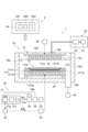
- FIG. 1 is a diagram for explaining a configuration example of a capacitively coupled plasma processing apparatus.
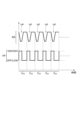
- FIG. 4 is a diagram showing an example of a waveform of an electrical bias.
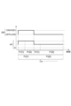
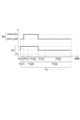
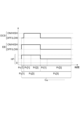
- 4 is an example timing diagram associated with a power supply system according to an exemplary embodiment.
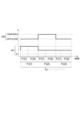
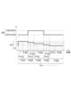
- 4 is an example timing diagram associated with a power supply system according to an exemplary embodiment.
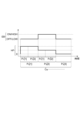
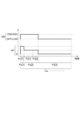
- 4 is an example timing diagram associated with a power supply system according to an exemplary embodiment.
- 4 is an example timing diagram associated with a power supply system according to an exemplary embodiment.
- 4 is an example timing diagram associated with a power supply system according to an exemplary embodiment.
- 4 is an example timing diagram associated with a power supply system according to an exemplary embodiment.
- 4 is an example timing diagram associated with a power supply system according to an exemplary embodiment.
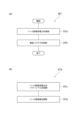
- FIG. 18(a) is a flowchart of a control method according to one exemplary embodiment
- FIG. 18(a) is a flowchart of a control method according to one exemplary embodiment
- 18(b) is a flowchart of step STa shown in FIG. 18(a).
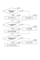
- 20 is a flowchart showing an example of processing in step STd shown in FIG. 18(b).
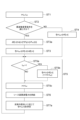
- 20 is a flowchart showing an example of processing in step ST7 shown in FIG. 19.
- 20 is a flowchart showing another example of the process in step STd shown in FIG. 18(b).
- 22 is a flowchart showing an example of processing in step ST7a shown in FIG. 21.
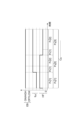
- 2 is a timing diagram associated with a power supply system according to an exemplary embodiment.
- FIG. 1 is a diagram for explaining an example of the configuration of a plasma processing system.
- the plasma processing system includes a plasma processing device 1 and a control unit 2.
- the plasma processing system is an example of a substrate processing system
- the plasma processing device 1 is an example of a substrate processing device.
- the plasma processing device 1 includes a plasma processing chamber 10, a substrate support unit 11, and a plasma generation unit 12.
- the plasma processing chamber 10 has a plasma processing space.
- the plasma processing chamber 10 also has at least one gas supply port for supplying at least one processing gas to the plasma processing space, and at least one gas exhaust port for exhausting gas from the plasma processing space.
- the gas supply port is connected to a gas supply unit 20 described later, and the gas exhaust port is connected to an exhaust system 40 described later.
- the substrate support unit 11 is disposed in the plasma processing space, and has a substrate support surface for supporting a substrate.
- the plasma generating unit 12 is configured to generate plasma from at least one processing gas supplied into the plasma processing space.
- the plasma formed in the plasma processing space may be capacitively coupled plasma (CCP), inductively coupled plasma (ICP), ECR plasma (Electron-Cyclotron-Resonance Plasma), Helicon Wave Plasma (HWP), or Surface Wave Plasma (SWP), etc.
- the control unit 2 processes computer-executable instructions that cause the plasma processing apparatus 1 to perform the various steps described in this disclosure.
- the control unit 2 may be configured to control each element of the plasma processing apparatus 1 to perform the various steps described herein. In one embodiment, a part or all of the control unit 2 may be included in the plasma processing apparatus 1.
- the control unit 2 may include a processing unit 2a1, a storage unit 2a2, and a communication interface 2a3.
- the control unit 2 is realized, for example, by a computer 2a.
- the processing unit 2a1 may be configured to perform various control operations by reading a program from the storage unit 2a2 and executing the read program. This program may be stored in the storage unit 2a2 in advance, or may be acquired via a medium when necessary.
- the acquired program is stored in the storage unit 2a2, and is read from the storage unit 2a2 by the processing unit 2a1 and executed.
- the medium may be various storage media readable by the computer 2a, or may be a communication line connected to the communication interface 2a3.
- the processing unit 2a1 may be a programmable logic device such as a CPU (Central Processing Unit) or an FPGA (Field-Programmable Gate Array).
- the storage unit 2a2 may include a RAM (Random Access Memory), a ROM (Read Only Memory), a HDD (Hard Disk Drive), an SSD (Solid State Drive), or a combination thereof.
- the communication interface 2a3 may communicate with the plasma processing device 1 via a communication line such as a LAN (Local Area Network).
- FIG. 1 is a diagram for explaining an example of the configuration of a capacitively coupled plasma processing device.
- the capacitively coupled plasma processing apparatus 1 includes a plasma processing chamber 10, a gas supply unit 20, a power supply system 30, and an exhaust system 40.
- the plasma processing apparatus 1 also includes a substrate support unit 11 and a gas inlet unit.
- the gas inlet unit is configured to introduce at least one processing gas into the plasma processing chamber 10.
- the gas inlet unit includes a shower head 13.
- the substrate support unit 11 is disposed in the plasma processing chamber 10.
- the shower head 13 is disposed above the substrate support unit 11. In one embodiment, the shower head 13 constitutes at least a part of the ceiling of the plasma processing chamber 10.
- the plasma processing chamber 10 has a plasma processing space 10s defined by the shower head 13, the sidewall 10a of the plasma processing chamber 10, and the substrate support unit 11.
- the plasma processing chamber 10 is grounded.
- the substrate support unit 11 is electrically insulated from the housing of the plasma processing chamber 10.
- the substrate support 11 includes a main body 111 and a ring assembly 112.
- the main body 111 has a central region 111a for supporting the substrate W and an annular region 111b for supporting the ring assembly 112.
- a wafer is an example of a substrate W.
- the annular region 111b of the main body 111 surrounds the central region 111a of the main body 111 in a plan view.
- the substrate W is disposed on the central region 111a of the main body 111
- the ring assembly 112 is disposed on the annular region 111b of the main body 111 so as to surround the substrate W on the central region 111a of the main body 111. Therefore, the central region 111a is also called a substrate support surface for supporting the substrate W, and the annular region 111b is also called a ring support surface for supporting the ring assembly 112.
- the main body 111 includes a base 1110 and an electrostatic chuck 1111.
- the base 1110 includes a conductive member.
- the electrostatic chuck 1111 is disposed on the base 1110.
- the electrostatic chuck 1111 includes a ceramic member 1111a and an electrostatic electrode 1111b disposed within the ceramic member 1111a.
- the ceramic member 1111a has a central region 111a.
- the ceramic member 1111a also has an annular region 111b.
- other members surrounding the electrostatic chuck 1111 such as an annular electrostatic chuck or an annular insulating member, may have the annular region 111b.
- the ring assembly 112 may be disposed on the annular electrostatic chuck or the annular insulating member, or may be disposed on both the electrostatic chuck 1111 and the annular insulating member.
- the ring assembly 112 includes one or more annular members.
- the one or more annular members include one or more edge rings and at least one cover ring.
- the edge rings are formed of a conductive or insulating material, and the cover rings are formed of an insulating material.
- the substrate support 11 may also include a temperature adjustment module configured to adjust at least one of the electrostatic chuck 1111, the ring assembly 112, and the substrate to a target temperature.
- the temperature adjustment module may include a heater, a heat transfer medium, a flow passage 1110a, or a combination thereof.
- a heat transfer fluid such as brine or a gas flows through the flow passage 1110a.
- the flow passage 1110a is formed in the base 1110, and one or more heaters are disposed in the ceramic member 1111a of the electrostatic chuck 1111.
- the substrate support 11 may also include a heat transfer gas supply configured to supply a heat transfer gas to a gap between the back surface of the substrate W and the central region 111a.
- the shower head 13 is configured to introduce at least one processing gas from the gas supply unit 20 into the plasma processing space 10s.
- the shower head 13 has at least one gas supply port 13a, at least one gas diffusion chamber 13b, and multiple gas inlets 13c.
- the processing gas supplied to the gas supply port 13a passes through the gas diffusion chamber 13b and is introduced into the plasma processing space 10s from the multiple gas inlets 13c.
- the shower head 13 also includes at least one upper electrode.
- the gas introduction unit may include, in addition to the shower head 13, one or more side gas injectors (SGI) attached to one or more openings formed in the sidewall 10a.
- SGI side gas injectors
- the gas supply unit 20 may include at least one gas source 21 and at least one flow controller 22.
- the gas supply unit 20 is configured to supply at least one process gas from a respective gas source 21 through a respective flow controller 22 to the showerhead 13.
- Each flow controller 22 may include, for example, a mass flow controller or a pressure-controlled flow controller.
- the gas supply unit 20 may include at least one flow modulation device that modulates or pulses the flow rate of the at least one process gas.
- the exhaust system 40 may be connected to, for example, a gas exhaust port 10e provided at the bottom of the plasma processing chamber 10.
- the exhaust system 40 may include a pressure regulating valve and a vacuum pump. The pressure in the plasma processing space 10s is adjusted by the pressure regulating valve.
- the vacuum pump may include a turbomolecular pump, a dry pump, or a combination thereof.
- the power supply system 30 includes a high frequency power supply 31 and a bias power supply 32.
- the power supply system 30 may further include a DC power supply 38.
- the high frequency power supply 31 constitutes the plasma generating unit 12 of one embodiment.
- the high frequency power supply 31 is configured to generate high frequency power.
- the high frequency power generated by the high frequency power supply 31 is referred to as source high frequency power HF.
- the source high frequency power HF has a frequency.
- the frequency of the source high frequency power HF is referred to as the source frequency.
- the source high frequency power HF has a sinusoidal waveform whose frequency is the source frequency.
- the source frequency can be a frequency within the range of 10 MHz to 150 MHz.
- the high frequency power supply 31 is electrically connected to the high frequency electrode via the matching box 33 and is configured to supply source high frequency power HF to the high frequency electrode.
- the high frequency electrode may be provided in the substrate support 11.
- the high frequency electrode may be at least one electrode provided in the conductive member or ceramic member 1111a of the base 1110. Alternatively, the high frequency electrode may be an upper electrode.
- the source high frequency power HF is supplied to the high frequency electrode, plasma is generated from the gas in the chamber 10.
- the matching device 33 has a variable impedance.
- the variable impedance of the matching device 33 is set to reduce reflection of the source high frequency power HF from the load.
- the matching device 33 can be controlled, for example, by the control unit 2.
- the high frequency power source 31 may include a signal generator 31g, a D/A converter 31c, and an amplifier 31a.
- the signal generator 31g generates a high frequency signal having a source frequency f.
- the signal generator 31g may be comprised of a programmable logic device such as a programmable processor or a field-programmable gate array (FPGA).
- the output of the signal generator 31g is connected to the input of the D/A converter 31c.
- the D/A converter 31c converts the high frequency signal from the signal generator 31g into an analog signal.
- the output of the D/A converter 31c is connected to the input of the amplifier 31a.
- the amplifier 31a amplifies the analog signal from the D/A converter 31c to generate the source high frequency power HF.
- the gain of the amplifier 31a is specified by the control unit 2 to the high frequency power source 31. Note that the high frequency power source 31 does not need to include the D/A converter 31c.
- the output of the signal generator 31g is connected to the input of the amplifier 31a, and the amplifier 31a amplifies the high frequency signal from the signal generator 31g to generate the source high frequency power HF.
- the bias power supply 32 is electrically coupled to the substrate support 11.
- the bias power supply 32 is electrically connected to a bias electrode in the substrate support 11 and is configured to supply an electric bias EB to the bias electrode.
- the bias electrode may be at least one electrode provided in the conductive member or ceramic member 1111a of the base 1110.
- the bias electrode may be common to the radio frequency electrode.
- FIG. 3 is a diagram showing an example of the waveform of the electric bias.
- the bias power supply 32 is configured to periodically apply an electric bias EB having a waveform period CW to the bias electrode. That is, the electric bias EB is applied to the bias electrode in each of a plurality of waveform periods CW which are repetitions of the waveform period CW .
- the waveform period CW is defined by a bias frequency fEB .
- the bias frequency fEB is, for example, a frequency not less than 50 kHz and not more than 27 MHz.
- the time length of the waveform period CW is the reciprocal of the bias frequency.
- the electric bias EB may be a bias high frequency power LF having a bias frequency. That is, the electric bias EB may have a sinusoidal waveform whose frequency is the bias frequency.
- the bias power supply 32 is electrically connected to the bias electrode via a matching device 34.
- the variable impedance of the matching device 34 is set to reduce the reflection of the bias high frequency power LF from the load.
- the electric bias EB may include a voltage pulse VP.
- the voltage pulse VP is applied to the bias electrode within a waveform period CW .
- the voltage pulse VP is applied to the bias electrode periodically at a time interval having the same length as the time length of the waveform period CW .
- the waveform of the voltage pulse VP may be a square wave, a triangular wave, or any other waveform.
- the polarity of the voltage of the voltage pulse VP is set so that a potential difference is generated between the substrate W and the plasma to attract ions from the plasma to the substrate W.
- the voltage pulse VP is applied to the bias electrode so that the waveform period CW includes a period during which the potential of the substrate W is negative.
- the voltage pulse VP applied to the bias electrode may have a negative potential, a positive potential, or a potential that changes between a positive potential and a negative potential.
- the voltage pulse VP may be a negative voltage pulse or a negative DC voltage pulse.
- the plasma processing apparatus 1 does not need to include a matching unit 34.
- the plasma processing apparatus 1 may further include a sensor 35 and/or a sensor 36.
- the sensor 35 is configured to measure the power level Pr of the reflected wave of the source high frequency power HF from the load.
- the sensor 35 includes, for example, a directional coupler.
- the directional coupler may be provided between the high frequency power supply 31 and the matching device 33.
- the sensor 35 may further be configured to measure the power level Pf of the forward wave of the source high frequency power HF.
- the power level Pr of the reflected wave measured by the sensor 35 is notified to the high frequency power supply 31.
- the power level Pf of the forward wave may be notified from the sensor 35 to the high frequency power supply 31.
- the sensor 35 may notify the high frequency power supply 31 of the reflectivity, i.e., Pr/Pf.
- the reflectivity may be determined from the power level Pf and the power level Pr in the high frequency power supply 31.
- a detection circuit 35b may be connected between the sensor 35 and the high frequency power supply 31, and the power level Pf and the power level Pr may be determined from the output of the detection circuit 35b.
- the sensor 36 includes a voltage sensor and a current sensor.
- the sensor 36 is configured to measure a voltage V S and a current I S in a power supply path that connects the high frequency power supply 31 and the high frequency electrode to each other.
- the source high frequency power HF is supplied to the high frequency electrode via this power supply path.
- the sensor 36 may be provided between the high frequency power supply 31 and the matching unit 33.
- the voltage V S and the current I S are notified to the high frequency power supply 31.
- the sensor 36 may notify the high frequency power supply 31 of an impedance Z L of a load of the high frequency power supply 31 determined from the voltage V S and the current I S.
- the impedance Z L may be determined from the voltage V S and the current I S in the high frequency power supply 31.
- the sensor 36 may notify the high frequency power supply 31 of a phase difference ⁇ between the voltage V S and the current I S.
- the phase difference ⁇ may be determined from the voltage V S and the current I S in the high frequency power supply 31.
- the sensor 36 may notify the high frequency power supply 31 of the reflection coefficient ⁇ determined from the voltage V S and the current I S.
- the reflection coefficient ⁇ may be determined in the high frequency power supply 31 from the voltage V S and the current I S.
- the DC power supply 38 is configured to apply a DC voltage DCS to the upper electrode.
- the DC power supply 38 may apply a negative DC voltage to the upper electrode.
- the DC power supply 38 may be a variable DC power supply.
- FIG. 4 to FIG. 17 is an example timing chart related to a power supply system according to one exemplary embodiment.
- Each of FIG. 4 to FIG. 17 shows the power level of the source high frequency power HF and the level of the electric bias EB.
- "ON" of the electric bias EB indicates that the electric bias EB is being supplied
- "OFF” of the electric bias EB indicates that the supply of the electric bias EB is stopped.
- "HIGH” of the electric bias EB indicates that an electric bias EB having a level higher than the level indicated by "LOW" is being supplied.
- the level of the electric bias EB is the power level of the bias high frequency power LF.
- the electric bias EB includes a voltage pulse VP
- the electric bias EB has a higher level as the energy of the ions attracted to the substrate W becomes higher.
- the level of the electric bias EB may be the absolute value of the voltage level of the voltage pulse VP in the negative direction relative to a reference voltage (e.g., 0 V).
- a duty ratio DVP is further shown.
- the duty ratio DVP is a ratio of the time length during which the voltage pulse VP is supplied to the waveform period CW .
- FIG. 14 a duty ratio of the time length during which the voltage pulse VP is supplied to the waveform period CW .
- a bias frequency fEB is further shown.
- a DC voltage DCS is further shown.
- "ON" of the DC voltage DCS indicates that the DC voltage DCS is being supplied, and "OFF" of the DC voltage DCS indicates that the supply of the DC voltage DCS is stopped.
- "HIGH” of the DC voltage DCS indicates that a DC voltage DCS having a level higher than the level indicated by "LOW” is being supplied.
- the level of the DC voltage DCS may be the absolute value of the voltage level of the DC voltage DCS in the negative direction relative to the reference voltage level (for example, 0 V).
- the power level of the source high frequency power HF from the high frequency power supply 31 is modulated.
- the power level of the source high frequency power HF from the high frequency power supply 31 is specified by a power supply control unit.
- the power supply control unit is configured to periodically modulate the power level of the source high frequency power HF in a repetition of a modulation period C M.
- the power supply control unit may be provided within the high frequency power supply 31 or may be provided outside the high frequency power supply 31.
- the signal generator 31g may function as the power supply control unit, or another device within the high frequency power supply 31 may function as the power supply control unit. Alternatively, the control unit 2 may function as the power supply control unit.
- the power supply control unit may be configured to periodically modulate the condition of the electric bias EB in the repetition of the modulation period C 1 M.
- the power supply control unit may periodically modulate the level of the electric bias EB in the repetition of the modulation period C 1 M.
- the power supply control unit may periodically modulate the duty ratio D VP in the repetition of the modulation period C 1 M.
- the power supply control unit may periodically modulate the bias frequency f EB in the repetition of the modulation period C 1 M.
- the power supply control unit may periodically modulate the voltage level of the direct current voltage DCS in the repetition of the modulation period C 1 M.
- the modulation period C M includes a plurality of subperiods P S.
- the numbers in parentheses following P S indicate the order of the subperiods P S in the modulation period C M.
- the modulation period C M includes at least two subperiods P S in which the power level of the source high frequency power HF is set to a level greater than zero and different from each other.
- each of the plurality of subperiods P S is a period during which the power level of the source high frequency power HF and the condition of the electric bias EB continue to be set to the same settings.
- each of the plurality of subperiods P S is a period during which the power level of the source high frequency power HF, the condition of the electric bias EB, and the output voltage level of the DC power supply 38 (i.e., the voltage level of the DC voltage DCS) continue to be set to the same settings.
- Each of the multiple sub-periods P S includes a feedback period P F [1] (first feedback period) that continues from its start when the source high frequency power HF has a power level greater than 0 watts. As shown in FIGS. 4 to 12, each of the multiple sub-periods P S may further include a feedback period P F [2] (second feedback period) as a remaining period following the feedback period P F [1]. Alternatively, at least one sub-period of the multiple sub-periods P S may include only the feedback period P F [1]. That is, at least one sub-period of the multiple sub-periods P S may coincide with the feedback period P F [1 ] . In the example shown in FIG.
- the sub-period P S [1] includes only the feedback period P F [1].
- each of the multiple sub-periods P S may include only the feedback period P F [1]. That is, each of the multiple sub-periods P S may coincide with the feedback period P F [1].
- the high frequency power supply 31 adjusts the source frequency f for each phase period P H in the modulation period C M in order to suppress reflection of the source high frequency power HF from the load.
- the source frequency f is specified to the high frequency power supply 31 by the power supply control unit.
- the adjustment of the source frequency f will be described with reference to (a) and (b) of FIG. 18 together with FIG. 2 to FIG. 17.
- (a) of FIG. 18 is a flow chart of a control method according to one exemplary embodiment
- (b) of FIG. 18 is a flow chart of step STa shown in (a) of FIG. 18.
- each part of the power supply system 30 is controlled by the power supply control unit.
- the method MT includes steps STa and STb.
- a source high frequency power HF is supplied from a high frequency power supply 31 to a high frequency electrode in order to generate plasma in a chamber 10 of the plasma processing apparatus 1.
- an electric bias EB is repeatedly supplied to the substrate support 11 (i.e., the bias electrode) at a time interval of a waveform period CW in order to attract ions from the plasma to a substrate W on the substrate support 11.
- the process STa includes a process STc and a process STd.
- the power level of the source high frequency power HF is periodically modulated in the repetition of the modulation period C 1 M.
- the level of the electric bias EB may be periodically modulated in the repetition of the modulation period C 1 M.
- the level of the direct current voltage DCS may be periodically modulated in the repetition of the modulation period C 1 M.
- step STd the source frequency f for each phase period P H in each modulation period C M is adjusted to suppress the degree of reflection of the source high frequency power HF.
- a modulation period C M [y] represents the y-th modulation period C M in the repetition of the modulation periods C M.
- a phase period P H [k] represents the k-th phase period in the modulation period C M.
- a phase period P H [j] represents the j-th phase period in the waveform period C W.
- a waveform period C W [m] represents the m-th waveform period C W in each of the feedback period P F [1] and the feedback period P F [2].
- a frequency prepared in advance for that phase period is used as the source frequency f.
- a frequency prepared in advance for that phase period is used as the source frequency f.
- multiple phase periods P H in a waveform period C W [m] in the feedback period P F [1] in each of the modulation periods C M [1] to C M [Y 1 ] multiple frequencies included in a frequency set prepared in advance for that waveform period are used as the source frequency f.
- Y 1 is an integer of 1 or more, for example, 5.
- a frequency determined by a second feedback described below may be used as the source frequency f.
- the multiple source frequencies f used in the multiple phase periods P H in the final waveform period C W in the immediately preceding feedback period P F [1] may be used, respectively.
- a frequency determined by a first feedback is used as the source frequency f.
- a frequency determined by a first feedback is used as the source frequency f.
- a frequency determined by a second feedback described later may be used as the source frequency f.
- the multiple source frequencies f used in the multiple phase periods P H in the final waveform period C W in the immediately preceding feedback period P F [1] may be used, respectively.
- Y2 may be Y1 + 1.
- a delay time may be provided between the modulation cycle C M [ Y1 ] and the modulation cycle C M [ Y2 ].
- the delay time may be on the order of several seconds.
- the source frequencies f used in the phase periods P H in the modulation cycle C M [ Y1 ] may be used as the source frequencies of the phase periods P H in each modulation cycle C M from immediately after the modulation cycle C M [ Y1 ] to immediately before the modulation cycle C M [ Y2 ].
- Fig. 19 is a flow chart showing an example of processing in step STd shown in Fig. 18(b).
- Fig. 20 is a flow chart showing an example of processing in step ST7 shown in Fig. 19.
- the repetition of the modulation period C M i.e., a plurality of modulation periods C M
- a plurality of waveform periods C W in a feedback period P F [2] in the modulation period C M [y] and I ref waveform periods C W immediately preceding that feedback period P F [2] form a periodic sequence C S.
- the source frequency f of the phase period P H [k] of the modulation period C M is determined based on a change in the source frequency f of the phase period P H [k] in the sequence of the preceding modulation periods C M and a change in the degree of reflection of the source high frequency power HF, so as to suppress the degree of reflection.
- the source frequency f of the phase period P H [j] in the waveform period C W [m] in the feedback period P F [2] in the modulation period C M [y] is determined so as to suppress the degree of reflection based on the change in the source frequency f of the phase period P H [j] in the series of the preceding multiple waveform periods C W in the same feedback period P F [2] and the change in the degree of reflection of the source high frequency power HF.
- the source frequency f is determined by the power supply control unit.
- each of the phase periods P H [k] in the sequence of modulation periods C M in the first feedback and the phase periods P H [j] in the sequence of waveform periods C W in the second feedback will be referred to as a phase period P H [n] of the periodic sequence C S.
- each of the modulation periods C M in the first feedback and the waveform periods C W in the second feedback will be referred to as a period C R.
- the step STd may include steps ST1 to ST7.
- the steps ST1 to ST7 are performed for each phase period P H in each cycle C R in the periodic sequence C S.
- step ST1 the power supply control unit sets i to I ini -I ref .
- "i" represents the order of the cycle C R included in the cycle sequence C S.
- “I ini” is initially “Y 2 ".
- “I ini -I ref” represents the order of the cycle C R one cycle before the I ini- th cycle C R included in the cycle sequence C S
- "I ref " is 1.
- "I ini " is initially "1”.
- I ini -I ref represents the order of the cycle C R I ref cycles before the I ini-th cycle C R included in the cycle sequence C S
- "I ref " is an integer equal to or greater than 1.
- I ref may be 1, 2, or an integer greater than 2.
- I ref when I ref is equal to or greater than 2, a relatively long processing time is ensured as the processing time for determining the source frequency for each phase period P H in the second feedback.
- the power supply control unit determines whether the degree of reflection Pd [i,n] is large enough to satisfy the frequency change condition.
- Pd [i,n] represents the degree of reflection of the phase period PH [n] in the i-th period C R [i] included in the periodic sequence C S.
- the frequency change condition is satisfied when the degree of reflection Pd [i,n] is larger than a threshold value.
- the frequency change condition may be satisfied when Pd [i,n] is larger than a first threshold value Pth1 [n].
- the first threshold value Pth1 for each of the multiple phase periods P H may be the same as or different from each other.
- the power supply control unit sets the source frequency f[i+I ref , n] according to equation (1) in step ST3.
- f[i+I ref ,n] f[i,n]+ ⁇ f[i,n]...(1)
- f[i,n] represents the source frequency f of the phase period P H [n] in the i-th period C R [i] contained in the periodic sequence C S
- ⁇ f[i,n] is a shift value whose initial value is set in advance.
- Step ST5 includes steps ST5a, ST5b, and ST5c.
- step ST5a it is determined whether I ref is greater than 1. If I ref is 1, the process proceeds to step ST5c. If I ref is greater than 1, in step ST5b, the power supply control unit sets f[i+h, n] to f[i, n]. The process of step ST5b is performed while incrementing h by 1 from 1 to I ref -1. Then, the process proceeds to step ST5c.
- step ST5c the power supply control unit increments i by 1+ Iref .
- the power supply control unit supplies a source high frequency power HF having a source frequency f[i,n] from the high frequency power supply 31 in a phase period P H [n] in a cycle C R [i] in the cycle sequence C S.
- the power supply control unit determines a source frequency f [i+Iref, n] for a phase period PH [n] in a subsequent cycle CR [i+ Iref ] in the periodic sequence Cs according to the degree of reflection Pd [i, n].
- the process ST7 starts with a process ST701.
- the power supply control unit judges whether or not the degree of reflection P d [i, n] is increasing.
- the degree of reflection P d [i, n] may be judged to be increasing when P d [i, n]>P d [i-I ref , n] is satisfied.
- the degree of reflection P d [ i, n] may be judged to be increasing when the degree of reflection in the phase period P H [n] is increasing over X cycles C R up to the i-th cycle C R [i] in the cycle sequence C S.
- "X" is an integer of 2 or more.
- the X cycles C R up to the i-th cycle C R [i] in the cycle sequence C S are represented by C R [ i-x ⁇ I ref ], and "x" is an integer from 0 to (X-1).
- the power supply control unit determines whether or not the shift direction change condition is satisfied.
- the shift direction change condition is satisfied when the absolute value of the difference between the source frequency f[i,n] and the source frequency f[i,n-u] of the (n-u)th phase period P H [n-u] in the cycle C R [i] and the absolute value of the difference between the source frequency f[i,n] and the source frequency f[i,n+u] of the (n+u)th phase period P H [n+u] in the cycle C R [i] are compared with a predetermined value, and it is determined that the change in the source frequency is large, and both the source frequency f[i,n-u] and the source frequency f[i,n+u] are larger or smaller than the source frequency f[i,n].
- the shift direction change condition is satisfied when the absolute value of the difference between the source frequency f[i,n] and the source frequency f[i,n-u] and the absolute value of the difference between the source frequency f[i,n] and the source frequency f[i,n+u] are each greater than a predetermined value, and both the source frequency f[i,n-u] and the source frequency f[i,n+u] are greater than or less than the source frequency f[i,n].
- u may be 1 or a number greater than 1.
- the shift direction change condition may be satisfied when u is any number within the range of 1 to a number greater than 1.
- step ST704 the power supply control unit changes the sign of the shift value ⁇ f[i, n] in step ST705. That is, in step ST705, the power supply control unit sets the shift value ⁇ f[i, n] according to equation (5).
- ⁇ f[i,n]
- sign() is a function that returns the sign of the number in parentheses
- u is the value of u when the shift direction change condition is satisfied.
- the power supply control unit determines whether the degree of reflection Pd [i,n] of the source high frequency power HF in the phase period PH[n] in the cycle C R [ i] of the periodic sequence C S is large enough to satisfy the frequency change condition.
- the frequency change condition is satisfied when the degree of reflection Pd [i,n] of the source high frequency power HF in the phase period PH [n] in the cycle C R [i] of the periodic sequence C S is larger than a threshold value.
- step ST708 the power supply control unit sets the source frequency f[i+ Iref , n] for the phase period P H [n] in the subsequent cycle C R [i+ Iref ] in the periodic sequence C S using equation (7).
- f[i+I ref ,n] f[i,n]+ ⁇ f[i,n]...(7)
- the frequency change condition may not be satisfied in step ST707 until the result of the comparison in the subsequent step ST707 between the degree of reflection in a phase period P H [n] in the cycle C R and the second threshold value P th2 [n] is determined that the degree of reflection is large.
- the second threshold value P th2 [n] is equal to or greater than the first threshold value P th1 [n].
- the second threshold value P th2 [n] may be greater than the first threshold value P th1 [n]. Note that the second threshold values P th2 [n] for each of the multiple phase periods P H [n] may be the same as or different from each other.
- a second threshold value P th2 [n] may be used as a threshold to be compared with the degree of reflection in the phase period P H [n] in a subsequent step ST707.
- a first threshold value P th1 [n] may be used as a threshold to be compared with the degree of reflection in the phase period P H [n] in a subsequent step ST707.
- the reflection of the source high frequency power HF is suppressed by adjusting the source frequency f[i+I ref , n] according to the degree of reflection P d [i, n].
- the shift direction change condition that is, when a large fluctuation in the source frequency that causes a large increase or decrease in the source frequency followed by a large increase or decrease in the source frequency occurs in each period C R , the sign of the shift value is changed. Therefore, according to the method MT, a large fluctuation in the source frequency in the period C R is suppressed.
- the source frequency is suppressed from being changed excessively. Furthermore, when the method MT is repeated, a high reproducibility of the time change of the source frequency can be achieved. Note that the step ST7 shown in FIG. 20 does not have to include steps ST704 to ST706.
- FIG. 21 is a flow chart showing another example of the process in step STd shown in Figure 18(b).
- Figure 22 is a flow chart showing an example of the process in step ST7a shown in Figure 21.
- the process in step STd shown in Figures 21 and 22 will be described below from the viewpoint of differences from the process shown in Figures 19 and 20.
- the power supply control unit sets the shift value ⁇ f[i,n] to a value according to the magnitude of the reflection degree P d [i,n].
- the power supply control unit sets the source frequency f[i,n] and the coefficient ⁇ [i,n] in the steps between process ST1 and process ST3.
- the source frequency f[i,n] and the coefficient ⁇ [i,n] i.e., the source frequency f[1,n] and the coefficient ⁇ [1,n] are initially set to respective values that have been set in advance.
- step ST2 If it is determined in step ST2 that the frequency change condition is satisfied, the power supply control unit sets the shift value ⁇ f[i, n] according to equation (9) in step ST3a between steps ST2 and ST3.
- ⁇ f [i, n] ⁇ [i, n] * (P d [i, n] - P th1 [n]) ... (9)
- the coefficient ⁇ [1, n] is a preset value.
- step ST7a the power supply control unit determines a source frequency f [i+Iref, n] for a phase period PH [n] in a subsequent cycle CR [i+ Iref ] in the periodic sequence Cs in accordance with the degree of reflection Pd [i, n].
- u is the value of u when the shift direction change condition is satisfied.
- step ST708a the power supply control unit sets the shift value ⁇ f[i, n] using equation (14).
- ⁇ f[i,n] ⁇ [i,n]*(P d [i,n] ⁇ P th1 [n]) ...(14)
- the frequency change condition may not be satisfied in step ST707 until the degree of reflection in a phase period P H [n] in the cycle C R is determined to be large as a result of the comparison in the subsequent step ST707 between the second threshold P th2 [n].
- the second threshold P th2 [n] is equal to or greater than the first threshold P th1 [n].
- the second threshold P th2 [n] may be greater than the first threshold P th1 [n].
- the second threshold P th2 [n] for each of the multiple phase periods P H [n] may be the same or different from each other.
- a second threshold value P th2 [n] may be used as a threshold to be compared with the degree of reflection in the phase period P H [n] in the subsequent step ST707.
- step ST707 If it is determined in step ST707 that the degree of reflection in a phase period P H [n] in any waveform cycle in the cycle sequence C S is greater than the second threshold value P th2 [n], a first threshold value P th1 [n] may be used as a threshold to be compared with the degree of reflection in the phase period P H [n] in the subsequent step ST707. Note that the step ST7a shown in FIG. 22 does not have to include the steps ST704, ST705a, and ST706a.
- the degree of reflection Pd [i,n] will be described below.
- the degree of reflection Pd [i,n] is obtained by obtaining a plurality of evaluation values at each of a plurality of sample time points in a phase period PH [n] in a cycle CR[i] in the periodic sequence C S.
- the plurality of evaluation values reflect the magnitude of reflection of the source high frequency power HF at each of the plurality of sample time points.
- the number of sample time points in each of the plurality of phase periods P H may be the same.
- the degree of reflection Pd [i,n] is a representative value of the evaluation values at each of a plurality of sample time points in the phase period PH[n] in the period CR [i] in the periodic sequence Cs .
- the representative value is an average value of the plurality of evaluation values, a weighted average value of the plurality of evaluation values, or a maximum value of the plurality of evaluation values.
- Each of the plurality of evaluation values may be the power level Pr of the reflected wave, the reflectivity (i.e., Pr/Pf), the magnitude of the difference between the impedance ZL and the characteristic impedance, or the reflection coefficient ⁇ , as measured values acquired by the sensors 35 and 36.
- Each of the plurality of evaluation values may be the difference between the resistance value of the input of the matching box 33 (i.e., the input of the matching box 33 on the high frequency power source 31 side) or the transmission system of the source high frequency power HF as viewed from the high frequency power source 31 and a predetermined resistance value (50 ⁇ , etc.).
- each of the plurality of evaluation values may be the difference between the phase difference between the voltage Vs and the current Is at the transmission system of the source high frequency power HF or the input of the matching box and a predetermined value (90 degrees, etc.).
- the degree of reflection Pd [i,n] is a weighted average of evaluation values at multiple sample time points in a phase period P H [n] in a cycle CR[i] in the periodic sequence C S.
- the power supply control unit obtains an average of multiple values obtained by multiplying the multiple evaluation values by a window function.
- the window function has a weight that decreases according to the time difference from the center of the phase period P H [n].
- a triangular window, a Gaussian window, a Hanning window, a Hamming window, or the like is used. According to the weighted average using such a window function, it is possible to suppress the variation in the calculated value of the degree of reflection Pd [i,n] that may be caused due to the phase of the source high frequency power HF in each phase period P H.
- the high frequency power supply 31 may supply the source high frequency power HF continuously over the entire period of the waveform period CW .
- the high frequency power supply 31 may pulse the source high frequency power HF within the waveform period CW . That is, the high frequency power supply 31 may supply a pulse of the source high frequency power HF within the waveform period CW .
- a chamber; a substrate support disposed within the chamber; A power supply system; Equipped with The power supply system includes: a radio frequency power source configured to provide a source radio frequency power to generate a plasma within the chamber; a bias power supply configured to supply an electrical bias to the substrate support, the electrical bias being repeated at a time interval of a waveform period, to attract ions from the plasma to a substrate on the substrate support; A power supply control unit; Including, the power supply controller is configured to periodically modulate a power level of the source RF power in a repeating modulation period; the modulation period includes a plurality of subperiods, the plurality of subperiods including at least two subperiods in which a power level of the source radio frequency power is set to a level greater than zero and different from one another, each of the at least two subperiods including a feedback period continuing from a start point thereof; the power supply control unit is configured to adjust a source frequency of the source high frequency power for a k-th phase period
- the power supply system further includes a DC power supply electrically connected to an upper electrode disposed above the substrate support; the power supply system is configured to maintain the power level of the source radio frequency power, the condition of the electrical bias, and the output voltage level of the DC power supply at the same settings during each of the plurality of sub-periods.
- the plasma processing apparatus according to E1.
- the electrical bias includes voltage pulses generated periodically at time intervals of the waveform period;
- the condition of the electrical bias includes at least one selected from the group consisting of a voltage level of the voltage pulse, a duty ratio of the voltage pulse, and a bias frequency that is the inverse of the time length of the waveform period.
- the electrical bias is a bias radio frequency power having a bias frequency that is the inverse of the time length of the waveform period;
- the conditions of the electrical bias include at least one selected from the group consisting of a power level of the bias high frequency power and a bias frequency.
- the feedback period is a first feedback period; each of the at least two subperiods includes a second feedback period following the first feedback period; the power supply control unit is configured to control the high frequency power supply so as to repeatedly use, in the second feedback period, the sequence of source frequencies used in the waveform period immediately before the second feedback period.
- the feedback period is a first feedback period; each of the at least two subperiods includes a second feedback period following the first feedback period; the power supply control unit is configured to adjust the source frequency for a jth phase period in each waveform cycle in the second feedback period of each of the at least two subperiods based on a change in the source frequency and a change in a degree of reflection of the source high frequency power in the jth phase period in a repetition of a preceding waveform cycle in each of the at least two subperiods, so as to suppress the degree of reflection of the source high frequency power.
- the plasma processing apparatus according to any one of E1 to E5.
- a radio frequency power supply configured to provide a source radio frequency power to generate a plasma in a chamber of the plasma processing apparatus; a bias power supply configured to repeatedly supply an electrical bias to a substrate support disposed within the chamber at a time interval of a waveform period to attract ions from the plasma to a substrate on the substrate support;
- a power supply control unit; Equipped with the power supply controller is configured to periodically modulate a power level of the source RF power in a repeating modulation period; the modulation period includes a plurality of subperiods, the plurality of subperiods including at least two subperiods in which a power level of the source radio frequency power is set to a level greater than zero and different from one another, each of the at least two subperiods including a feedback period continuing from a start point thereof;
- the power supply control unit is configured to adjust a source frequency of the source high frequency power for a k-th phase period in the modulation cycle included in the feedback period based on a change in the source frequency
- [E10] (a) providing a source radio frequency power from a radio frequency power source to generate a plasma in a chamber of a plasma processing device; (b) applying an electrical bias to a substrate support disposed within the chamber at a repeating time interval of a waveform period to attract ions from the plasma to a substrate on the substrate support; Including, The (a) is (c) periodically modulating a power level of the source radio frequency power in a repeating modulation period, the modulation period including a plurality of subperiods, the plurality of subperiods including at least two subperiods in which the power level of the source radio frequency power is set to a level greater than zero and different from one another, each of the at least two subperiods including a feedback period continuing from a start of the at least two subperiods; (d) adjusting a source frequency of the source high frequency power for a kth phase period in the modulation cycle included in the feedback time period, the source frequency for the kth phase period in
- Plasma processing device 10: Chamber
- 11 Substrate support
- 30 Power supply system
- 31 High frequency power supply
- 32 Bias power supply.
Landscapes
- Physics & Mathematics (AREA)
- Engineering & Computer Science (AREA)
- Plasma & Fusion (AREA)
- Chemical & Material Sciences (AREA)
- Analytical Chemistry (AREA)
- Drying Of Semiconductors (AREA)
- Plasma Technology (AREA)
Abstract
Description
f[i+Iref,n]=f[i,n]+Δf[i,n] …(1)
なお、f[i,n]は、周期系列CSに含まれるi番目の周期CR[i]内の位相期間PH[n]のソース周波数fを表している、また、Δf[i,n]は、シフト値であり、その初期値は事前に設定されている。
f[i+Iref,n]=f[i,n] …(2)
Δf[i,n]=Δf[i-Iref,n] …(3)
Δf[i,n]=-Δf[i-Iref,n] …(4)
Δf[i,n]=|Δf[i-Iref,n]|*sign(f[i,n]-f[i,n-u]) …(5)
ここで、sign()は、括弧内の数値の符号を返す関数である。また、uは、シフト方向変更条件を満たすときのuの値である。
Δf[i,n]=Δf[i,n] …(6)
f[i+Iref,n]=f[i,n]+Δf[i,n] …(7)
f[i+Iref,n]=f[i,n] …(8)
Δf[i,n]=α[i,n]*(Pd[i,n]-Pth1[n]) …(9)
ここで、係数α[1,n]は、事前に設定された数値である。
α[i,n]=α[i-Iref,n] …(10)
α[i,n]=-α[i-Iref,n] …(11)
α[i,n]=|α[i-Iref,n]|*sign(f[i,n]-f[i,n-u]) …(12)
ここで、uは、シフト方向変更条件を満たすときのuの値である。
α[i,n]=α[i,n] …(13)
Δf[i,n]=α[i,n]*(Pd[i,n]-Pth1[n]) …(14)
チャンバと、
前記チャンバ内に配置された基板支持部と、
電源システムと、
を備え、
前記電源システムは、
前記チャンバ内でプラズマを生成するために、ソース高周波電力を供給するように構成された高周波電源と、
前記基板支持部上の基板に前記プラズマからイオンを引き込むために、波形周期の時間間隔で繰り返して前記基板支持部に電気バイアスを供給するように構成されたバイアス電源と、
電源制御部と、
を含み、
前記電源制御部は、変調周期の繰り返しにおいて前記ソース高周波電力のパワーレベルを周期的に変調するように構成されており、
前記変調周期は複数の副期間を含み、該複数の副期間は前記ソース高周波電力のパワーレベルがゼロよりも大きく且つ互いに異なるレベルに設定される少なくとも二つの副期間を含み、該少なくとも二つの副期間の各々はその開始時点から続くフィードバック期間を含み、
前記電源制御部は、前記フィードバック期間に含まれる前記変調周期内のk番目の位相期間のための前記ソース高周波電力のソース周波数を、先行する前記変調周期の繰り返しにおける前記k番目の位相期間の前記ソース周波数の変化と前記ソース高周波電力の反射の度合いの変化に基づき、該ソース高周波電力の該反射の度合いを抑制するように、調整するよう構成されている、
プラズマ処理装置。
前記電源システムは、前記複数の副期間の各々において前記ソース高周波電力のパワーレベル及び前記電気バイアスの条件の各々を同一の設定のまま継続するように構成されている、E1に記載のプラズマ処理装置。
前記電源システムは、前記基板支持部の上方に配置された上部電極に電気的に接続された直流電源を更に含み、
前記電源システムは、前記複数の副期間の各々において前記ソース高周波電力のパワーレベル、前記電気バイアスの条件、及び前記直流電源の出力電圧レベルの各々を同一の設定のまま継続するように構成されている、
E1に記載のプラズマ処理装置。
前記電気バイアスは、前記波形周期の時間間隔で周期的に発生される電圧パルスを含み、
前記電気バイアスの前記条件は、前記電圧パルスの電圧レベル、前記電圧パルスのデューティ比、及び前記波形周期の時間長の逆数であるバイアス周波数からなる群から選択される少なくとも一つを含む、
E2又はE3に記載のプラズマ処理装置。
前記電気バイアスは、前記波形周期の時間長の逆数であるバイアス周波数を有するバイアス高周波電力であり、
前記電気バイアスの前記条件は、前記バイアス高周波電力の電力レベル及び前記バイアス周波数からなる群から選択される少なくとも一つを含む、
E2又はE3に記載のプラズマ処理装置。
前記フィードバック期間は、第1のフィードバック期間であり、
前記少なくとも二つの副期間の各々は、前記第1のフィードバック期間に続く第2のフィードバック期間を含み、
前記電源制御部は、前記第2のフィードバック期間の直前の前記波形周期において用いられた前記ソース周波数の系列を該第2のフィードバック期間において繰り返して用いるように前記高周波電源を制御するよう構成されている、
E1~E5の何れか一項に記載のプラズマ処理装置。
前記フィードバック期間は、第1のフィードバック期間であり、
前記少なくとも二つの副期間の各々は、前記第1のフィードバック期間に続く第2のフィードバック期間を含み、
前記電源制御部は、前記少なくとも二つの副期間の各々の前記第2のフィードバック期間における各波形周期内のj番目の位相期間のための前記ソース周波数を、前記少なくとも二つの副期間の各々において先行する前記波形周期の繰り返しにおける前記j番目の位相期間の前記ソース周波数の変化と前記ソース高周波電力の反射の度合いの変化に基づき、該ソース高周波電力の該反射の度合いを抑制するように、調整するよう構成されている、
E1~E5の何れか一項に記載のプラズマ処理装置。
前記少なくとも二つの副期間の各々の長さは、前記フィードバック期間の長さと一致する、E1~E5の何れか一項に記載のプラズマ処理装置。
プラズマ処理装置のチャンバ内でプラズマを生成するために、ソース高周波電力を供給するように構成された高周波電源と、
前記チャンバ内に設けられた基板支持部上の基板に前記プラズマからイオンを引き込むために、波形周期の時間間隔で繰り返して前記基板支持部に電気バイアスを供給するように構成されたバイアス電源と、
電源制御部と、
を備え、
前記電源制御部は、変調周期の繰り返しにおいて前記ソース高周波電力のパワーレベルを周期的に変調するように構成されており、
前記変調周期は複数の副期間を含み、該複数の副期間は前記ソース高周波電力のパワーレベルがゼロよりも大きく且つ互いに異なるレベルに設定される少なくとも二つの副期間を含み、該少なくとも二つの副期間の各々はその開始時点から続くフィードバック期間を含み、
前記電源制御部は、前記フィードバック期間に含まれる前記変調周期内のk番目の位相期間のための前記ソース高周波電力のソース周波数を、先行する前記変調周期の繰り返しにおける前記k番目の位相期間の前記ソース周波数の変化と前記ソース高周波電力の反射の度合いの変化に基づき、該ソース高周波電力の該反射の度合いを抑制するように、調整するよう構成されている、
電源システム。
(a)プラズマ処理装置のチャンバ内でプラズマを生成するために高周波電源からソース高周波電力を供給する工程と、
(b)前記チャンバ内に配置された基板支持部上の基板に前記プラズマからイオンを引き込むために、波形周期の時間間隔で繰り返して前記基板支持部に電気バイアスを供給する工程と、
を含み、
前記(a)は、
(c)変調周期の繰り返しにおいて前記ソース高周波電力のパワーレベルを周期的に変調する工程であり、前記変調周期は複数の副期間を含み、該複数の副期間は前記ソース高周波電力のパワーレベルがゼロよりも大きく且つ互いに異なるレベルに設定される少なくとも二つの副期間を含み、該少なくとも二つの副期間の各々はその開始時点から続くフィードバック期間を含む、該工程と、
(d)前記フィードバック期間に含まれる前記変調周期内のk番目の位相期間のための前記ソース高周波電力のソース周波数を調整する工程であり、該変調周期内の該k番目の位相期間のための該ソース周波数は、先行する前記変調周期の繰り返しにおける前記k番目の位相期間の前記ソース周波数の変化と前記ソース高周波電力の反射の度合いの変化に基づき、該ソース高周波電力の該反射の度合いを抑制するように、調整される、該工程と、
を含む、制御方法。
Claims (10)
- チャンバと、
前記チャンバ内に配置された基板支持部と、
電源システムと、
を備え、
前記電源システムは、
前記チャンバ内でプラズマを生成するために、高周波電力を供給するように構成された高周波電源と、
前記基板支持部上の基板に前記プラズマからイオンを引き込むために、波形周期の時間間隔で繰り返して前記基板支持部に電気バイアスを供給するように構成されたバイアス電源と、
電源制御部と、
を含み、
前記電源制御部は、変調周期の繰り返しにおいて前記高周波電力のパワーレベルを周期的に変調するように構成されており、
前記変調周期は複数の副期間を含み、該複数の副期間は前記高周波電力のパワーレベルがゼロよりも大きく且つ互いに異なるレベルに設定される少なくとも二つの副期間を含み、該少なくとも二つの副期間の各々はその開始時点から続くフィードバック期間を含み、
前記電源制御部は、前記フィードバック期間に含まれる前記変調周期内のk番目の位相期間のための前記高周波電力の周波数を、先行する前記変調周期の繰り返しにおける前記k番目の位相期間の前記高周波電力の周波数の変化と前記高周波電力の反射の度合いの変化に基づき、該高周波電力の該反射の度合いを抑制するように、調整するよう構成されている、
プラズマ処理装置。 - 前記電源システムは、前記複数の副期間の各々において前記高周波電力のパワーレベル及び前記電気バイアスの条件の各々を同一の設定のまま継続するように構成されている、請求項1に記載のプラズマ処理装置。
- 前記電源システムは、前記基板支持部の上方に配置された上部電極に電気的に接続された直流電源を更に含み、
前記電源システムは、前記複数の副期間の各々において前記高周波電力のパワーレベル、前記電気バイアスの条件、及び前記直流電源の出力電圧レベルの各々を同一の設定のまま継続するように構成されている、
請求項1に記載のプラズマ処理装置。 - 前記電気バイアスは、前記波形周期の時間間隔で周期的に発生される電圧パルスを含み、
前記電気バイアスの前記条件は、前記電圧パルスの電圧レベル、前記電圧パルスのデューティ比、及び前記波形周期の時間長の逆数であるバイアス周波数からなる群から選択される少なくとも一つを含む、
請求項2又は3に記載のプラズマ処理装置。 - 前記電気バイアスは、前記波形周期の時間長の逆数であるバイアス周波数を有するバイアス高周波電力であり、
前記電気バイアスの前記条件は、前記バイアス高周波電力の電力レベル及び前記バイアス周波数からなる群から選択される少なくとも一つを含む、
請求項2又は3に記載のプラズマ処理装置。 - 前記フィードバック期間は、第1のフィードバック期間であり、
前記少なくとも二つの副期間の各々は、前記第1のフィードバック期間に続く第2のフィードバック期間を含み、
前記電源制御部は、前記第2のフィードバック期間の直前の前記波形周期において用いられた前記高周波電力の前記周波数の系列を該第2のフィードバック期間において繰り返して用いるように前記高周波電源を制御するよう構成されている、
請求項1~3の何れか一項に記載のプラズマ処理装置。 - 前記フィードバック期間は、第1のフィードバック期間であり、
前記少なくとも二つの副期間の各々は、前記第1のフィードバック期間に続く第2のフィードバック期間を含み、
前記電源制御部は、前記少なくとも二つの副期間の各々の前記第2のフィードバック期間における各波形周期内のj番目の位相期間のための前記高周波電力の前記周波数を、前記少なくとも二つの副期間の各々において先行する前記波形周期の繰り返しにおける前記j番目の位相期間の前記高周波電力の前記周波数の変化と前記高周波電力の反射の度合いの変化に基づき、該高周波電力の該反射の度合いを抑制するように、調整するよう構成されている、
請求項1~3の何れか一項に記載のプラズマ処理装置。 - 前記少なくとも二つの副期間の各々の長さは、前記フィードバック期間の長さと一致する、請求項1~3の何れか一項に記載のプラズマ処理装置。
- プラズマ処理装置のチャンバ内でプラズマを生成するために、高周波電力を供給するように構成された高周波電源と、
前記チャンバ内に設けられた基板支持部上の基板に前記プラズマからイオンを引き込むために、波形周期の時間間隔で繰り返して前記基板支持部に電気バイアスを供給するように構成されたバイアス電源と、
電源制御部と、
を備え、
前記電源制御部は、変調周期の繰り返しにおいて前記高周波電力のパワーレベルを周期的に変調するように構成されており、
前記変調周期は複数の副期間を含み、該複数の副期間は前記高周波電力のパワーレベルがゼロよりも大きく且つ互いに異なるレベルに設定される少なくとも二つの副期間を含み、該少なくとも二つの副期間の各々はその開始時点から続くフィードバック期間を含み、
前記電源制御部は、前記フィードバック期間に含まれる前記変調周期内のk番目の位相期間のための前記高周波電力の周波数を、先行する前記変調周期の繰り返しにおける前記k番目の位相期間の前記高周波電力の前記周波数の変化と前記高周波電力の反射の度合いの変化に基づき、該高周波電力の該反射の度合いを抑制するように、調整するよう構成されている、
電源システム。 - (a)プラズマ処理装置のチャンバ内でプラズマを生成するために高周波電源から高周波電力を供給する工程と、
(b)前記チャンバ内に配置された基板支持部上の基板に前記プラズマからイオンを引き込むために、波形周期の時間間隔で繰り返して前記基板支持部に電気バイアスを供給する工程と、
を含み、
前記(a)は、
(c)変調周期の繰り返しにおいて前記高周波電力のパワーレベルを周期的に変調する工程であり、前記変調周期は複数の副期間を含み、該複数の副期間は前記高周波電力のパワーレベルがゼロよりも大きく且つ互いに異なるレベルに設定される少なくとも二つの副期間を含み、該少なくとも二つの副期間の各々はその開始時点から続くフィードバック期間を含む、該工程と、
(d)前記フィードバック期間に含まれる前記変調周期内のk番目の位相期間のための前記高周波電力の周波数を調整する工程であり、該変調周期内の該k番目の位相期間のための前記高周波電力の前記周波数は、先行する前記変調周期の繰り返しにおける前記k番目の位相期間の前記高周波電力の前記周波数の変化と前記高周波電力の反射の度合いの変化に基づき、該高周波電力の該反射の度合いを抑制するように、調整される、該工程と、
を含む、制御方法。
Priority Applications (4)
| Application Number | Priority Date | Filing Date | Title |
|---|---|---|---|
| CN202480069307.9A CN122095748A (zh) | 2023-11-10 | 2024-11-05 | 等离子体处理装置、电源系统和控制方法 |
| EP24888707.7A EP4780143A1 (en) | 2023-11-10 | 2024-11-05 | Plasma processing device, power supply system, and control method |
| JP2025505617A JP7883046B2 (ja) | 2023-11-10 | 2024-11-05 | プラズマ処理装置、電源システム、及び制御方法 |
| KR1020267017256A KR20260112145A (ko) | 2023-11-10 | 2024-11-05 | 플라즈마 처리 장치, 전원 시스템 및 제어 방법 |
Applications Claiming Priority (2)
| Application Number | Priority Date | Filing Date | Title |
|---|---|---|---|
| JP2023192179 | 2023-11-10 | ||
| JP2023-192179 | 2023-11-10 |
Publications (1)
| Publication Number | Publication Date |
|---|---|
| WO2025100412A1 true WO2025100412A1 (ja) | 2025-05-15 |
Family
ID=95695556
Family Applications (1)
| Application Number | Title | Priority Date | Filing Date |
|---|---|---|---|
| PCT/JP2024/039311 Pending WO2025100412A1 (ja) | 2023-11-10 | 2024-11-05 | プラズマ処理装置、電源システム、及び制御方法 |
Country Status (6)
| Country | Link |
|---|---|
| EP (1) | EP4780143A1 (ja) |
| JP (1) | JP7883046B2 (ja) |
| KR (1) | KR20260112145A (ja) |
| CN (1) | CN122095748A (ja) |
| TW (1) | TW202545240A (ja) |
| WO (1) | WO2025100412A1 (ja) |
Citations (5)
| Publication number | Priority date | Publication date | Assignee | Title |
|---|---|---|---|---|
| JP2009246091A (ja) | 2008-03-31 | 2009-10-22 | Tokyo Electron Ltd | プラズマ処理装置及びプラズマ処理方法及びコンピュータ読み取り可能な記憶媒体 |
| JP2017073247A (ja) * | 2015-10-06 | 2017-04-13 | 東京エレクトロン株式会社 | プラズマ処理装置のインピーダンス整合のための方法 |
| US20210057188A1 (en) * | 2019-08-22 | 2021-02-25 | Advanced Micro-Fabrication Equipment Inc. China | Radio frequency power supply system, plasma processor, and frequency-tuning matching |
| JP2021106354A (ja) * | 2019-12-27 | 2021-07-26 | 株式会社ダイヘン | 高周波電源システム |
| JP2022071824A (ja) * | 2020-10-28 | 2022-05-16 | 東京エレクトロン株式会社 | プラズマ処理装置 |
-
2024
- 2024-11-05 JP JP2025505617A patent/JP7883046B2/ja active Active
- 2024-11-05 EP EP24888707.7A patent/EP4780143A1/en active Pending
- 2024-11-05 WO PCT/JP2024/039311 patent/WO2025100412A1/ja active Pending
- 2024-11-05 CN CN202480069307.9A patent/CN122095748A/zh active Pending
- 2024-11-05 KR KR1020267017256A patent/KR20260112145A/ko active Pending
- 2024-11-07 TW TW113142711A patent/TW202545240A/zh unknown
Patent Citations (5)
| Publication number | Priority date | Publication date | Assignee | Title |
|---|---|---|---|---|
| JP2009246091A (ja) | 2008-03-31 | 2009-10-22 | Tokyo Electron Ltd | プラズマ処理装置及びプラズマ処理方法及びコンピュータ読み取り可能な記憶媒体 |
| JP2017073247A (ja) * | 2015-10-06 | 2017-04-13 | 東京エレクトロン株式会社 | プラズマ処理装置のインピーダンス整合のための方法 |
| US20210057188A1 (en) * | 2019-08-22 | 2021-02-25 | Advanced Micro-Fabrication Equipment Inc. China | Radio frequency power supply system, plasma processor, and frequency-tuning matching |
| JP2021106354A (ja) * | 2019-12-27 | 2021-07-26 | 株式会社ダイヘン | 高周波電源システム |
| JP2022071824A (ja) * | 2020-10-28 | 2022-05-16 | 東京エレクトロン株式会社 | プラズマ処理装置 |
Also Published As
| Publication number | Publication date |
|---|---|
| JPWO2025100412A1 (ja) | 2025-05-15 |
| CN122095748A (zh) | 2026-05-26 |
| EP4780143A1 (en) | 2026-07-22 |
| TW202545240A (zh) | 2025-11-16 |
| KR20260112145A (ko) | 2026-07-16 |
| JP7883046B2 (ja) | 2026-06-30 |
Similar Documents
| Publication | Publication Date | Title |
|---|---|---|
| JP7753427B2 (ja) | プラズマ処理装置 | |
| US12542255B2 (en) | Plasma processing apparatus and plasma processing method | |
| US20250014872A1 (en) | Plasma processing method and plasma processing apparatus | |
| JP7474913B2 (ja) | 電源システム | |
| US20250149296A1 (en) | Plasma processing apparatus and plasma processing method | |
| WO2023132300A1 (ja) | プラズマ処理装置、電源システム、制御方法、プログラム、及び記憶媒体 | |
| JP7678233B2 (ja) | プラズマ処理装置、ソース高周波電力のソース周波数を制御する方法、及び記憶媒体 | |
| JP7622252B2 (ja) | プラズマ処理装置、電源システム、制御方法、プログラム、及び記憶媒体 | |
| JP7756056B2 (ja) | エッチング方法及びプラズマ処理装置 | |
| US20260120998A1 (en) | Plasma processing apparatus and plasma processing method | |
| TW202545240A (zh) | 電漿處理裝置、電源系統、及控制方法 | |
| WO2025105243A1 (ja) | 電源システム、プラズマ処理装置、及び制御方法 | |
| JP2023129234A (ja) | プラズマ処理装置 | |
| WO2024162108A1 (ja) | プラズマ処理装置、電源システム、及び制御方法 | |
| JP7721820B2 (ja) | プラズマ処理装置、電源システム、及びソース周波数を制御する方法 | |
| JP2024119243A (ja) | プラズマ処理装置、電源システム、及びプラズマ処理方法 | |
| WO2023074816A1 (ja) | プラズマ処理装置、給電システム、制御方法、プログラム、及び記憶媒体 | |
| WO2025057636A1 (ja) | プラズマ処理装置 | |
| WO2024106256A1 (ja) | プラズマ処理装置及びプラズマ処理方法 | |
| WO2025204583A1 (ja) | プラズマ処理装置、電源システム、及び制御方法 | |
| WO2024106257A1 (ja) | プラズマ処理装置及びプラズマ処理方法 |
Legal Events
| Date | Code | Title | Description |
|---|---|---|---|
| ENP | Entry into the national phase |
Ref document number: 2025505617 Country of ref document: JP Kind code of ref document: A |
|
| WWE | Wipo information: entry into national phase |
Ref document number: 2025505617 Country of ref document: JP |
|
| 121 | Ep: the epo has been informed by wipo that ep was designated in this application |
Ref document number: 24888707 Country of ref document: EP Kind code of ref document: A1 |
|
| ENP | Entry into the national phase |
Ref document number: 1020267017256 Country of ref document: KR Free format text: ST27 STATUS EVENT CODE: A-0-1-A10-A15-NAP-PA0105 (AS PROVIDED BY THE NATIONAL OFFICE) |
|
| WWE | Wipo information: entry into national phase |
Ref document number: 11202602713S Country of ref document: SG |
|
| WWP | Wipo information: published in national office |
Ref document number: 11202602713S Country of ref document: SG |
|
| NENP | Non-entry into the national phase |
Ref country code: DE |