WO2025100397A1 - 真空ポンプおよび該真空ポンプに用いられる流入ガイド部品 - Google Patents
真空ポンプおよび該真空ポンプに用いられる流入ガイド部品 Download PDFInfo
- Publication number
- WO2025100397A1 WO2025100397A1 PCT/JP2024/039255 JP2024039255W WO2025100397A1 WO 2025100397 A1 WO2025100397 A1 WO 2025100397A1 JP 2024039255 W JP2024039255 W JP 2024039255W WO 2025100397 A1 WO2025100397 A1 WO 2025100397A1
- Authority
- WO
- WIPO (PCT)
- Prior art keywords
- disk
- inflow guide
- disks
- rotating
- rotating disk
- Prior art date
- Legal status (The legal status is an assumption and is not a legal conclusion. Google has not performed a legal analysis and makes no representation as to the accuracy of the status listed.)
- Pending
Links
Images









Classifications
-
- F—MECHANICAL ENGINEERING; LIGHTING; HEATING; WEAPONS; BLASTING
- F04—POSITIVE - DISPLACEMENT MACHINES FOR LIQUIDS; PUMPS FOR LIQUIDS OR ELASTIC FLUIDS
- F04D—NON-POSITIVE-DISPLACEMENT PUMPS
- F04D19/00—Axial-flow pumps
- F04D19/02—Multi-stage pumps
- F04D19/04—Multi-stage pumps specially adapted to the production of a high vacuum, e.g. molecular pumps
Definitions
- the present invention relates to a vacuum pump and an inlet guide part used in the vacuum pump.
- Patent Document 1 JP Patent Publication No. 2015-102076 (Patent Document 1) is a background technology of this technical field.
- the vacuum pump of the embodiment of the present invention is a composite vacuum pump equipped with a vacuum pump component that effectively connects the exhaust pipes and a Siegbahn type exhaust mechanism.
- the fixed disk has a spiral groove (helical groove) with peaks and valleys, and has a protrusion (projection) on either the inner diameter part that faces the rotating cylinder (rotating body cylindrical part) or the inner diameter side of the fixed cylinder arranged on the outer circumference side.
- the rotating disk also has a spiral groove (helical groove) with peaks and valleys, and has a protrusion (projection) on either the outer diameter part of the rotating cylinder arranged on the inner circumference side or the outer diameter part of the rotating disk that faces the spacer.” (See Abstract).
- Patent Document 1 discloses a configuration in which a protrusion is provided in the return flow path of a Siegbahn type (also called Sigbahn) molecular pump to connect the intake side pipe, which has an exhaust function, with the exhaust side pipe. Patent Document 1 states that this configuration can improve exhaust efficiency.
- a Siegbahn type also called Sigbahn
- this Sigburn type exhaust mechanism has excellent back pressure dependency, and that this can be improved, for example, by combining it with other exhaust mechanisms or by increasing the number of stages.
- This "back pressure dependency” is an index that represents the degree of influence that back pressure (exhaust port pressure) has on suction pressure (intake port pressure) in a vacuum exhaust system, and the lower the degree of influence, the better the back pressure dependency.
- back pressure dependency improves, the exhaust speed decreases.
- the present application includes a number of means for solving the above problems.
- a casing having an intake port; A rotor shaft disposed within the casing; one or more rotating disks rotatable with the rotor shaft; one or more fixed disks arranged to face each of the one or more rotating disks in the axial direction and each having a spiral groove having a valley portion and a peak portion on an opposing surface; Equipped with a gas flow passage is formed by the spiral groove facing the one or more rotating disks;
- a vacuum pump that exhausts a gas introduced from the inlet port by interaction between the one or more rotating disks and the one or more fixed disks,
- the gas inlet passage may further include an inflow guide portion for guiding the inflow of the gas, the inflow guide portion being disposed closer to the inlet port than a first rotating disk that is closer to the inlet port among the one or more rotating disks.
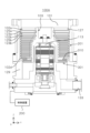
- FIG. 1 is a vertical cross-sectional view of an example of a turbomolecular pump.
- FIG. 2 is an example of a circuit diagram of an amplifier circuit for controlling the rotor shaft of a turbomolecular pump.
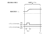
- FIG. 3 is an example of a time chart showing control when the current command value is larger than the detection value.
- FIG. 4 is an example of a time chart showing control when the current command value is smaller than the detection value.
- FIG. 5 is a vertical sectional view of another turbomolecular pump.
- FIG. 6 is a partially enlarged view of FIG.
- FIG. 7 is a schematic cross-sectional view taken along line VII-VII in FIG.
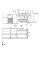
- FIG. 8 is a plan view of an example of a fixed disk.
- FIG. 9 is an example of a bottom view of the fixed disk.
- FIG. 10 is an example of a vertical cross-sectional view of a fixed disk.
- FIG. 11 is a graph showing a schematic relationship between the intake pressure and the back pressure of a Sigburn type exhaust mechanism.
- FIG. 12 is a vertical cross-sectional view of a turbomolecular pump according to one embodiment.
- FIG. 13 is a partially enlarged view of FIG.
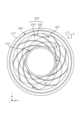
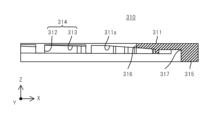
- FIG. 14 is an example of a bottom view of the inflow guide portion according to one embodiment.
- FIG. 15 is a cross-sectional view taken along line XV-XV of FIG.
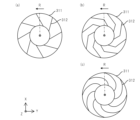
- FIG. 16 is a schematic diagram illustrating the shape of the peaks of the inflow guide portion.
- FIG. 17 is a graph showing the results of a simulation of the relationship between the inner radius of the inlet guide portion and the Sigburn stage inlet pressure.
- FIG. 18 is an example of a partial cross-sectional view of an inflow guide portion according to another embodiment.
- Fig. 1 shows the basic configuration of a turbomolecular pump 100, which is an example of a vacuum pump.
- the upper part of Fig. 1 is the upstream (intake) side of this turbomolecular pump 100, and an intake port 101 is connected to a vacuum chamber (not shown) of a target device such as a semiconductor manufacturing device.
- the lower part of Fig. 1 is the downstream (exhaust) side of the turbomolecular pump 100, and an exhaust port 133 is connected to, for example, an auxiliary pump (not shown).
- This turbomolecular pump 100 can be used in a reverse vertical position, a horizontal position, or an inclined position in addition to the vertical position shown in Fig. 1.
- FIG. 1 A longitudinal cross-sectional view of this turbomolecular pump 100 is shown in FIG. 1.
- the turbomolecular pump 100 has an intake port 101 formed at the upper end of a cylindrical outer tube 127.
- a rotor 103 is provided, which has a plurality of rotors 102 (102a, 102b, 102c, ...) that are turbine blades for sucking in and exhausting gas, formed radially around its periphery in multiple stages.
- a rotor shaft 113 is attached to the center of this rotor 103, and this rotor shaft 113 is supported in the air and its position is controlled by, for example, a five-axis controlled magnetic bearing.
- the rotor 103 is generally made of a metal such as aluminum or an aluminum alloy.
- the upper radial electromagnets 104 are arranged in pairs on the X-axis and Y-axis.
- Four upper radial sensors 107 are provided in close proximity to the upper radial electromagnets 104 and corresponding to each of the upper radial electromagnets 104.
- the upper radial sensors 107 are, for example, inductance sensors or eddy current sensors having conductive windings, and detect the position of the rotor shaft 113 based on the change in inductance of the conductive winding, which changes according to the position of the rotor shaft 113.
- the upper radial sensors 107 are configured to detect the radial displacement of the rotor shaft 113, i.e., the rotating body 103 fixed thereto, and send it to the control device 200.
- a compensation circuit having a PID adjustment function generates an excitation control command signal for the upper radial electromagnet 104 based on the position signal detected by the upper radial sensor 107, and the amplifier circuit 150 (described later) shown in FIG. 2 controls the excitation of the upper radial electromagnet 104 based on this excitation control command signal, thereby adjusting the upper radial position of the rotor shaft 113.
- the rotor shaft 113 is made of a material with high magnetic permeability (iron, stainless steel, etc.) and is attracted by the magnetic force of the upper radial electromagnet 104. Such adjustment is performed independently in the X-axis direction and the Y-axis direction.
- the lower radial electromagnet 105 and the lower radial sensor 108 are arranged in the same manner as the upper radial electromagnet 104 and the upper radial sensor 107, and adjust the lower radial position of the rotor shaft 113 in the same manner as the upper radial position.
- axial electromagnets 106A and 106B are arranged above and below a circular metal disk 111 provided at the bottom of rotor shaft 113.
- Metal disk 111 is made of a high magnetic permeability material such as iron.
- An axial sensor 109 is provided to detect the axial displacement of rotor shaft 113, and the axial position signal is sent to control device 200.
- a compensation circuit having, for example, a PID adjustment function generates excitation control command signals for the axial electromagnet 106A and the axial electromagnet 106B based on the axial position signal detected by the axial sensor 109, and the amplifier circuit 150 controls the excitation of the axial electromagnet 106A and the axial electromagnet 106B based on these excitation control command signals, so that the axial electromagnet 106A attracts the metal disk 111 upward by magnetic force, and the axial electromagnet 106B attracts the metal disk 111 downward, thereby adjusting the axial position of the rotor shaft 113.
- control device 200 appropriately adjusts the magnetic force that the axial electromagnets 106A and 106B exert on the metal disk 111, magnetically levitating the rotor shaft 113 in the axial direction and holding it in space without contact.
- the amplifier circuit 150 that controls the excitation of the upper radial electromagnet 104, the lower radial electromagnet 105, and the axial electromagnets 106A and 106B will be described later.
- motor 121 has multiple magnetic poles arranged circumferentially to surround rotor shaft 113. Each magnetic pole is controlled by control device 200 so as to rotate rotor shaft 113 via electromagnetic force acting between the magnetic poles and rotor shaft 113.
- Motor 121 also incorporates a rotational speed sensor, such as a Hall element, resolver, or encoder (not shown), and the rotational speed of rotor shaft 113 is detected by the detection signal of this rotational speed sensor.
- phase sensor (not shown) is attached near the lower radial sensor 108 to detect the phase of rotation of the rotor shaft 113.
- the control device 200 uses the detection signals of both this phase sensor and the rotation speed sensor to detect the position of the magnetic pole.
- the fixed blades 123 are arranged with a small gap between the rotating blades 102 (102a, 102b, 102c).
- the rotating blades 102 (102a, 102b, 102c%) are formed at a predetermined angle from a plane perpendicular to the axis of the rotor shaft 113 in order to transport exhaust gas molecules downwards through collision.
- the fixed blades 123 (123a, 123b, 123c%) are made of metals such as aluminum, iron, stainless steel, copper, etc., or alloys containing these metals as components.
- the fixed blades 123 are also formed at a predetermined angle from a plane perpendicular to the axis of the rotor shaft 113, and are arranged alternately with the stages of the rotor blades 102 toward the inside of the outer cylinder 127.
- the outer peripheral end of the fixed blades 123 is supported by being inserted between a plurality of stacked fixed blade spacers 125 (125a, 125b, 125c, etc.).
- the fixed wing spacer 125 is a ring-shaped member, and is made of metals such as aluminum, iron, stainless steel, copper, or alloys containing these metals as components.
- An outer cylinder 127 is fixed to the outer periphery of the fixed wing spacer 125 with a small gap between them.
- a base portion 129 is disposed at the bottom of the outer cylinder 127.
- An exhaust port 133 is formed in the base portion 129, and is connected to the outside. Exhaust gas that enters the intake port 101 from the chamber (vacuum chamber) side and is transferred to the base portion 129 is sent to the exhaust port 133.
- a threaded spacer 131 is disposed between the lower part of the fixed vane spacer 125 and the base part 129.
- the threaded spacer 131 is a cylindrical member made of metal such as aluminum, copper, stainless steel, iron, or an alloy containing these metals, and has a plurality of helical thread grooves 131a engraved on its inner peripheral surface.
- the helical direction of the thread groove 131a is the direction in which the molecules of the exhaust gas are transported toward the exhaust port 133 when they move in the rotation direction of the rotor 103.
- a cylindrical part 102d hangs down from the lowest part of the rotor 103, which is connected to the rotor vanes 102 (102a, 102b, 102c, etc.).
- the outer peripheral surface of this cylindrical part 102d is cylindrical and protrudes toward the inner peripheral surface of the threaded spacer 131, and is adjacent to the inner peripheral surface of the threaded spacer 131 with a predetermined gap therebetween.
- the exhaust gas transferred to the thread groove 131a by the rotor 102 and the fixed blade 123 is guided by the thread groove 131a and sent to the base portion 129.
- the base portion 129 is a disk-shaped member that forms the base of the turbomolecular pump 100, and is generally made of a metal such as iron, aluminum, or stainless steel.
- the base portion 129 not only physically holds the turbomolecular pump 100, but also functions as a heat conduction path, so it is desirable to use a metal that is rigid and has high thermal conductivity, such as iron, aluminum, or copper.
- the rotor 102 and the fixed blades 123 act to draw exhaust gas from the chamber through the intake port 101.
- the rotation speed of the rotor 102 is usually 20,000 rpm to 90,000 rpm, and the peripheral speed at the tip of the rotor 102 reaches 200 m/s to 400 m/s.
- the exhaust gas drawn in from the intake port 101 passes between the rotor 102 and the fixed blades 123 and is transferred to the base part 129.
- the temperature of the rotor 102 rises due to frictional heat generated when the exhaust gas comes into contact with the rotor 102 and conduction of heat generated by the motor 121, but this heat is transferred to the fixed blades 123 side by radiation or conduction by gas molecules of the exhaust gas.
- the fixed blade spacers 125 are joined together at their outer periphery and transmit to the outside heat received by the fixed blades 123 from the rotor blades 102 and frictional heat generated when exhaust gas comes into contact with the fixed blades 123.
- the threaded spacer 131 is disposed on the outer periphery of the cylindrical portion 102d of the rotor 103, and that the thread groove 131a is engraved on the inner periphery of the threaded spacer 131.
- a thread groove is engraved on the outer periphery of the cylindrical portion 102d, and a spacer having a cylindrical inner periphery is disposed around it.
- the electrical equipment section which is composed of the upper radial electromagnet 104, upper radial sensor 107, motor 121, lower radial electromagnet 105, lower radial sensor 108, axial electromagnets 106A and 106B, and axial sensor 109, may be covered by a stator column 122 and a predetermined pressure may be maintained inside the stator column 122 with a purge gas to prevent the gas sucked in from the intake port 101 from entering the electrical equipment section.
- piping (not shown) is provided in the base portion 129, and purge gas is introduced through this piping.
- the introduced purge gas is sent to the exhaust port 133 through the gaps between the protective bearing 120 and the rotor shaft 113, between the rotor and stator of the motor 121, and between the stator column 122 and the inner cylindrical portion of the rotor blades 102.
- the turbomolecular pump 100 requires control based on specific parameters (e.g., characteristics corresponding to the model) that are individually adjusted and identified for the model.
- the turbomolecular pump 100 has an electronic circuit section 141 inside its body.
- the electronic circuit section 141 is composed of a semiconductor memory such as an EEP-ROM, electronic components such as semiconductor elements for accessing the memory, and a substrate 143 for mounting these components.
- This electronic circuit section 141 is housed below a rotational speed sensor (not shown) near the center of the base section 129 that constitutes the lower part of the turbomolecular pump 100, and is closed by an airtight bottom cover 145.
- some process gases introduced into the chamber have the property of solidifying when their pressure exceeds a predetermined value or their temperature falls below a predetermined value.
- the pressure of the exhaust gas is lowest at the intake port 101 and highest at the exhaust port 133. If the pressure of the process gas exceeds a predetermined value or its temperature falls below a predetermined value while the process gas is being transferred from the intake port 101 to the exhaust port 133, the process gas solidifies and adheres to and accumulates inside the turbomolecular pump 100.
- a solid product e.g., AlCl 3
- the deposits narrow the pump flow path, causing a decrease in the performance of the turbomolecular pump 100.
- the above-mentioned product is prone to solidification and adhesion in high pressure areas near the exhaust port 133 and near the threaded spacer 131.
- a heater (not shown) or a circular water-cooled tube 149 is wrapped around the outer periphery of the base portion 129, and a temperature sensor (e.g., a thermistor) (not shown) is embedded in the base portion 129, and the heating of the heater and the cooling by the water-cooled tube 149 are controlled based on the signal from the temperature sensor to keep the temperature of the base portion 129 at a constant high temperature (set temperature) (hereinafter referred to as TMS; TMS; Temperature Management System).
- TMS constant high temperature
- one end of the electromagnet winding 151 constituting the upper radial electromagnet 104 etc. is connected to the positive pole 171a of the power supply 171 via the transistor 161, and the other end is connected to the negative pole 171b of the power supply 171 via the current detection circuit 181 and the transistor 162.
- the transistors 161 and 162 are so-called power MOSFETs, and have a structure in which a diode is connected between the source and drain.
- the transistor 161 has its diode cathode terminal 161a connected to the positive electrode 171a, and its anode terminal 161b connected to one end of the electromagnet winding 151.
- the transistor 162 has its diode cathode terminal 162a connected to the current detection circuit 181, and its anode terminal 162b connected to the negative electrode 171b.
- the current regeneration diode 165 has its cathode terminal 165a connected to one end of the electromagnet winding 151 and its anode terminal 165b connected to the negative pole 171b.
- the current regeneration diode 166 has its cathode terminal 166a connected to the positive pole 171a and its anode terminal 166b connected to the other end of the electromagnet winding 151 via a current detection circuit 181.
- the current detection circuit 181 is composed of, for example, a Hall sensor type current sensor or an electrical resistance element.
- the amplifier circuit 150 configured as above corresponds to one electromagnet. Therefore, if the magnetic bearing is controlled on five axes and there are a total of ten electromagnets 104, 105, 106A, and 106B, a similar amplifier circuit 150 is configured for each electromagnet, and the ten amplifier circuits 150 are connected in parallel to the power supply 171.
- the amplifier control circuit 191 is configured, for example, by a digital signal processor section (hereinafter referred to as a DSP section) (not shown) of the control device 200, and this amplifier control circuit 191 switches the transistors 161 and 162 on and off.
- a DSP section digital signal processor section
- the amplifier control circuit 191 compares the current value detected by the current detection circuit 181 (a signal reflecting this current value is called a current detection signal 191c) with a predetermined current command value. Then, based on the result of this comparison, it determines the size of the pulse width (pulse width times Tp1, Tp2) to be generated within a control cycle Ts, which is one period of PWM control. As a result, gate drive signals 191a, 191b having this pulse width are output from the amplifier control circuit 191 to the gate terminals of transistors 161, 162.
- a voltage of about 50 V is used for the power supply 171 so that the current flowing through the electromagnet winding 151 can be rapidly increased (or decreased).
- a capacitor (not shown) is usually connected between the positive pole 171a and the negative pole 171b of the power supply 171 to stabilize the power supply 171.
- electromagnet current iL the current flowing through the electromagnet winding 151
- electromagnet current iL the current flowing through the electromagnet winding 151
- both transistors 161 and 162 are turned on for a time period equivalent to pulse width time Tp1 only once during control cycle Ts (e.g., 100 ⁇ s) as shown in FIG. 3. Therefore, during this period, electromagnet current iL increases toward current value iLmax (not shown) that can flow from positive pole 171a to negative pole 171b via transistors 161 and 162.
- both transistors 161 and 162 are turned off for a time period equivalent to pulse width time Tp2 only once during control cycle Ts, as shown in FIG. 4. Therefore, during this period, electromagnet current iL decreases from negative pole 171b to positive pole 171a, toward current value iLmin (not shown) that can be regenerated via diodes 165 and 166.
- the outer cylinder 127 and the base portion 129 are mainly combined to form a single housing (hereinafter referred to as the "casing").
- the exhaust mechanism provided in the casing can be divided into a turbomolecular pump mechanism portion composed of the rotor 102 and the fixed blades 123, etc., and a groove exhaust mechanism portion composed of the cylindrical portion 102d and the threaded spacer 131, etc.
- the groove exhaust mechanism portion is not limited to being composed of the cylindrical portion 102d and the threaded spacer 131, etc., and may be composed of, for example, a Sigburn type exhaust mechanism portion 301 (described later) or a Holweck type exhaust mechanism portion.
- the exhaust mechanism of the turbomolecular pump 100 may be composed of any one of the groove exhaust mechanism portions, or a combination of two or more of them.
- Fig. 5 is a vertical cross-sectional view of the turbomolecular pump 100A
- Fig. 6 is a partial enlarged view showing the right side of the rotation axis of the rotor shaft 113 in Fig. 5.
- the turbomolecular pump 100A includes, as a groove exhaust mechanism, the above-mentioned turbomolecular pump mechanism 201 and a Sigburn type exhaust mechanism 301.
- the Sigburn type exhaust mechanism 301 is provided in the next stage (immediately downstream side) of the turbomolecular pump mechanism 201 so as to be spatially continuous with it.
- FIG. 5 differs from FIG. 1 in that the groove exhaust mechanism is a Sigburn type exhaust mechanism 301, but the other basic configurations are the same. Therefore, the configuration and effects of the common parts will not be described again.
- the turbomolecular pump 100A may be equipped with another groove exhaust mechanism, such as a Holweck type exhaust mechanism (not shown), in the next stage (immediately downstream) of the Sigburn type exhaust mechanism 301.
- the Sigburn type exhaust mechanism part 301 is a Sigburn type exhaust mechanism, and is generally composed of a rotating disk 320 (320a, 320b) and a fixed disk 330 (330a).
- the rotating disk 320 (320a, 320b) and the fixed disk 330 (330a) are composed of metals such as aluminum, iron, stainless steel, copper, etc., or alloys containing these metals as components.
- the rotating disks 320 are generally circular plates, and are integrally formed on the outer periphery of the cylindrical rotor 103. Each rotating disk 320a, 320b is arranged coaxially with the rotor 103 and spaced apart in the axial direction.
- the rotating disks 320 (320a, 320b) rotate in the same direction (rotational direction) as the rotor 103 and the rotor blades 102, etc., when driven by the motor 121.
- the Sigburn type exhaust mechanism unit 301 has two (two stages) rotating disks 320a, 320b, but depending on the combination with the fixed disk, the number of rotating disks may be one (one stage) or three (three stages) or more. In the following, of one (single stage) or multiple (multiple stages) rotating disks 320, the rotating disk 320 that is positioned closest to the intake port 101 may be referred to as the first rotating disk 320a.
- the fixed disk 330 (330a) is generally an annular plate body and is integrally assembled to the casing.
- the fixed disk 330 (330a) may be composed of a single annular plate body, or may be composed of a plurality of divided pieces that are divided into arc-shaped pieces.
- the fixed disk 330a is disposed between the two rotating disks 320a and 320b with a predetermined clearance.
- the Sigburn type exhaust mechanism unit 301 is provided with one (one stage) fixed disk 330a, but depending on the combination with the rotating disk, there may be two (one stage) or more fixed disks.
- the fixed disk disposed closest to the intake port 101 among the one (one stage) or multiple (multiple stages) fixed disks 330 may be referred to as the first fixed disk 330a.
- the number of stages of the fixed disk 330 is one, and the number of stages of the rotating disk 320 is two.
- These rotating disks 320 and fixed disks 330 are arranged alternately from the intake port 101 side in the order of rotating disk 320 (first rotating disk 320a), fixed disk 330 (first fixed disk 330a), and rotating disk 320 (second rotating disk 320b).
- a spiral groove is provided on the opposing surface of at least one of the opposing rotating disk 320 and fixed disk 330.
- the rotating disk 320 is a substantially flat plate
- the spiral groove 334 is provided on both sides of the fixed disk 330, i.e., on both the upstream side (the side facing the intake port 101) and the downstream side (the side facing the intake port 101).
- FIG. 7 is a schematic cross-sectional view taken along line VII-VII in FIG. 5, and shows the fixed disk 330 of the Sigburn type exhaust mechanism 301 as viewed from the intake port 101 side.
- FIGS. 8 to 10 are examples of plan views, bottom views, and partial cross-sectional views of the fixed disk 330.
- the fixed disk 330 has, for example, a substantially annular disk portion 331 and a ridge portion 332 protruding from the disk portion 331 toward the rotating disk 320.
- the rotating body 103, the rotor shaft 113, etc. are inserted through a through hole in the center of the disk portion 331.
- the fixed disk 330 of this embodiment has a substantially annular fixed spacer 335 (see FIG. 10, etc.) integrally formed on the outer periphery of one surface of the disk portion 331 (here, the surface on the intake port 101 side).
- the fixed spacer 335 is an element that performs the same function as the fixed wing spacer 125 described above.
- a plurality of ridges 332 are provided so as to extend in a spiral line (swirl line).
- the ridges 332 provided on the upstream surface of the fixed disk 330 are shown by solid lines, and the ridges 332 provided on the downstream surface are shown by dotted lines.
- the ridges 332 provided on the upstream surface extend in the same direction as the rotation direction (forward direction) as they move from the outside (outer circumference) to the inside (inner circumference) in the radial direction perpendicular to the axial direction.
- the ridges 332 provided on the downstream surface extend in the opposite direction to the ridges 332 provided on the upstream surface in a plan view as they move from the inside to the outside in the radial direction.
- the ridges 332 on the downstream surface extend in the same direction (forward direction) as the rotation direction (arrow R) as they move from the inside (inner circumference side) to the outside (outer circumference side) in the radial direction when viewed from the bottom.
- the surface of the disk portion 331 on which the peaks 332 are not provided becomes a valley portion 333 that is recessed relative to the peaks 332.
- the peaks 332 and the valley portion 333 form a spiral groove 334.
- a gas flow path for transporting gas is formed by this spiral groove 334 of the fixed disk 330 and the rotating disk 320 that faces it.
- the width and depth of the spiral groove 334 may be adjusted, for example, so that the flow path step area gradually decreases toward the downstream side.
- gas molecules move from the outside to the inside in the radial direction in a spiral gas flow path constructed on the upstream side of the fixed disk 330, and then move from the inside to the outside in the radial direction in a gas flow path constructed on the downstream side of the fixed disk 330, and are sent to the exhaust port 133.
- the gas molecules move from the outside to the inside in the radial direction in the spiral gas flow path as shown by the solid arrow, and on the downstream side of the fixed disk 330, the gas molecules are transported from the inside to the outside in the radial direction in the gas flow path as shown by the dotted arrow.
- Indices used to express the exhaust performance of a vacuum pump generally include “exhaust speed,” “compression performance,” and “back pressure performance.” These indicators are defined, for example, in the Japanese Industrial Standard JIS B 8329-1:2015, and the values of each indicator can be understood in accordance with the standard. Of these indicators, “exhaust speed” is an indicator expressed as the volume of gas passing through the intake port per unit time. “Compression performance” is an indicator of how much gas can be compressed, and is expressed as the ratio of the exhaust port pressure to the intake port pressure when the flow rate is 0 (zero). "Back pressure performance,” as mentioned above, is an indicator of the degree to which a change in back pressure affects the suction pressure.
- Figure 11 is a graph that shows a schematic relationship between suction pressure and back pressure to explain the exhaust performance of a Sigburn exhaust system.
- the horizontal axis shows back pressure (the pressure at the exhaust port of the Sigburn exhaust system), and the vertical axis shows suction pressure (the pressure at the intake port of the Sigburn exhaust system), both of which are expressed on a logarithmic scale.
- the unit of exhaust port pressure is [Torr], and the unit of intake port pressure (Ps) in this case is typically [mTorr].
- the Sigburn exhaust mechanism has better back pressure performance than other exhaust mechanisms. If you want to further improve this back pressure performance, it is effective to increase the gas flow path length, that is, to increase the number of stages in the Sigburn exhaust mechanism part 301. Increasing the gas flow path length is also effective in improving compression performance. However, if the number of stages in the Sigburn exhaust mechanism part 301 is increased, the curve showing the relationship between suction pressure and back pressure is shifted to the upper right as shown in Figure 11 (c) (see “multiple stages” in the figure). In other words, there is a tradeoff between trying to improve back pressure performance and decreasing exhaust speed.
- a turbomolecular pump 300 according to the present technology will be described with reference to Fig. 12 to Fig. 18.
- Fig. 12 is a vertical cross-sectional view of the turbomolecular pump 300 according to one embodiment, and Fig. 13 is a partially enlarged view thereof.
- the turbomolecular pump 300 is provided with an inflow guide portion 310 on the downstream side of the turbomolecular pump mechanism portion 201 and immediately upstream of the Sigburn type exhaust mechanism portion 301.
- Fig. 12 is the same as Fig. 5 except that the inflow guide portion 310 is provided, and therefore repeated description of the configuration and the operation and effect of the common portions will be omitted.
- the inflow guide section 310 is an element that guides the flow of gas flowing into the Sigburn type exhaust mechanism section 301.
- the inflow guide section 310 is provided upstream of the first rotating disk 320a of the Sigburn type exhaust mechanism section 301 with a specified clearance between them.
- the inflow guide section 310 is generally an annular plate body, and is a static element that is integrally assembled to the casing.
- the inflow guide section 310 is made of metals such as aluminum, iron, stainless steel, copper, etc., or alloys that contain these metals as components.
- Fig. 14 is an example of a bottom view (viewed from the exhaust port 133 side) of the inflow guide portion 310
- Fig. 15 is a cross-sectional view taken along line XV-XV of Fig. 14.
- Fig. 16 is a schematic diagram for explaining the shape of the peaks of the inflow guide portion.
- the inflow guide portion 310 includes a guide disk 311 and a ridge portion 312.
- the inflow guide portion 310 of this embodiment includes a substantially annular fixed spacer 315 integrally formed on the outer circumferential edge portion of an opposing surface 311a (the surface on the exhaust port 133 side) that faces the first rotating disk 320a.
- the fixed spacer 315 is an element that performs the same function as the fixed vane spacer 125 described above.
- the guide disk 311 is a plate body having a substantially circular ring shape.
- the inner diameter of the guide disk 311 is typically configured to be larger than the inner diameter of the first fixed disk 330a.
- the guide disk 311 and the first rotating disk 320a are configured to produce a molecular drag effect when the first rotating disk 320a rotates.
- the plate surface of the guide disk 311 may be flat, or may be inclined so that the thickness gradually increases from the center to the outer periphery, as shown in FIG. 15.
- the rotating body 103, the rotor shaft 113, etc. are inserted into the through hole in the center of the guide disk 311.
- the ridges 312 are integrally formed with the guide disc 311 so as to protrude from the guide disc 311 towards the first rotating disc 320a.
- the ridges 312 are formed on the opposing surface 311a of the guide disc 311 that faces the first rotating disc 320a, and are not formed on the opposite surface (i.e. the upstream side).
- the ridges 312 in this embodiment have a band-like shape with a substantially rectangular cross section.
- the guide disc 311 in this embodiment has multiple ridges 312, but the number of ridges 312 is not particularly limited and may be one or more.
- the peaks 312 are generally spiral-shaped (wound-shaped), as shown in FIG. 14, for example.
- the peaks 312 extend radially from the inside to the outside in the same direction as the direction of rotation (forward direction). More specifically, as shown in FIG. 16(a) to (c), for example, the peaks 312 are configured so that the outer circumferential side is inclined in the forward direction of the rotation direction (arrow R) and the inner circumferential side is inclined in the opposite direction to the rotation direction, relative to the radial direction perpendicular to the rotation axis of the rotor 103.
- Each peak 312 may be formed in a straight line, for example, as shown in FIG. 16(a). Also, each peak 312 may be formed in a broken line shape that is bent at one or more points, for example, as shown in FIG. 16(b). Furthermore, each peak 312 may be formed in a smoothly curved line, for example, as shown in FIG. 16(c). Each peak 312 may have any combination of these shapes, as long as it extends in the same direction as the rotation direction as it moves from the inside to the outside in the radial direction. When multiple peaks 312 are provided on one guide disc 311, the peaks 312 may have the same shape, or some or all of them may have different shapes.
- a portion of the opposing surface 311a of the guide disk 311 where the peaks 312 are not provided becomes a valley 313 that is recessed relative to the peaks 312 (see FIG. 15).
- the peaks 312 and the valleys 313 form a spiral groove 314.
- the space surrounded by this spiral groove 314 of the guide disk 311 and the first rotating disk 320a facing it can serve as an introduction gas flow path primarily for introducing gas into the Sigburn type exhaust mechanism 301.
- the analytical model of the flow path of the Sigburn type exhaust mechanism for the simulation was created by extracting the gas flow path from the position where it passed through the turbomolecular pump mechanism 201 to the position where it passed through the Sigburn type exhaust mechanism 301, based on the CAD model of the turbomolecular pump 300 shown in Figures 6 and 12, etc. Note that in order to evaluate the exhaust characteristics of the Sigburn type exhaust mechanism 301 in more detail, the Sigburn type exhaust mechanism 301 of the analytical model was a multi-stage Sigburn with four rotating disks 320 and three fixed disks 330.
- the pressure at the stage preceding the Sigburn type exhaust mechanism i.e., suction pressure
- the pressure at the position passing through the Sigburn type exhaust mechanism i.e., back pressure
- the Reynolds Averaged Navier-Stokes (RANS) model was used for turbulence analysis, and the k- ⁇ model was applied to evaluate the Reynolds stress, simulating the pressure distribution of the compressed fluid N2 in the flow path.
- the suction pressure was calculated for the case where the inflow guide portion 310 was not provided (reference) and for the case where the inflow guide portion 310 was provided and its inner diameter was changed in three ways (No. 1 to 3). Below, we will explain how to express the change in the inner diameter of the inflow guide portion 310 with reference to Figure 13.
- the inner diameter of the inflow guide portion 310 When the inner diameter of the inflow guide portion 310 is changed, its shape can be expressed from various viewpoints. As one index, it can be expressed by the position of the inner peripheral end portion 316 (see FIG. 13, etc.) of the inflow guide portion 310 in the radial direction relative to the opposing first rotating disk 320a. This is because it is considered that the inflow guide portion 310 can suitably guide the gas toward the Sigburn type exhaust mechanism portion 301 by the molecular drag effect generated between the inflow guide portion 310 and the first rotating disk 320a, and the momentum given to the gas molecules is considered to be related to the overlapping ratio between the inflow guide portion 310 and the first rotating disk 320a.
- the shapes of the multiple rotating disks 320 (320a%) in the analysis model are essentially the same, so the following explanation will be based on rotating disk 320. If multiple rotating disks 320 (320a%) are provided and have different shapes, the "rotating disk 320" in the following explanation can be read as the "first rotating disk 320a.”
- the position (root) where the rotating disk 320 is connected to the rotor 103 is defined as the base end 321 of the rotating disk 320, and the ratio of the position of the rotating disk 320 from the base end 321 to the inner peripheral end 316 of the inflow guide portion 310 is expressed.
- the outer peripheral end of the rotating disk 320 is defined as the outer peripheral end 322.
- the base end 321 of the rotating disk 320 is located at a distance from the center of the rotating disk 320 by the radius of the rotor 103 (hereinafter, for convenience, referred to as the "inner peripheral radius R RI of the rotating disk 320").
- R RO is the radius of the outer circumference of the rotating disk 320, and is the dimension from the center of the rotating disk 320 to the outer peripheral end 322.
- the positions of the inner peripheral end 316 of the inflow guide portion 310 in the three analytical models are as follows: Simulation No. 1: 26%, Simulation No. 2: 57%, Simulation No. 3: 80%. Note that this index indicates that the larger the numerical value, the larger the inner diameter (or inner radius) of the inflow guide portion 310 and the smaller the overlap rate with the rotating disk 320.
- the “radial dimension L G2 of the flow passage area” is an area of the Sigburn type exhaust mechanism 301 that can become a gas flow passage, and in the radial direction, it is an area from the base end 321 of the rotating disk 320 to the base ends 317, 337 of the inflow guide part 310 or the fixed disk 330.
- the base end 317 of the inflow guide part 310 is the position where the guide disk 311 connects to the fixed spacer 315 (the position where the guide disk 311 protrudes from the inner peripheral surface of the fixed spacer 315).
- the base end 337 of the fixed disk 330 is the position where the disk part 331 connects to the fixed spacer 335 (the position where the disk part 331 protrudes from the inner peripheral surface of the fixed spacer 335).
- R GO is the outer circumferential radius of guide disk 311 of inflow guide portion 310, and is the dimension from the center of inflow guide portion 310 to base end portion 317 (i.e., does not include fixed spacer 315).
- R SO is the outer circumferential radius of disk portion 331 of fixed disk 330, and is the dimension from the center of fixed disk 330 to base end portion 337 (i.e., does not include fixed spacer 335).
- the positions of the inner peripheral end 316 of the three simulated inflow guide sections 310 are Simulation No. 1: 25%, Simulation No. 2: 55%, and Simulation No. 3: 78%.
- This index indicates that the larger the numerical value, the larger the inner diameter (or inner radius) of the inflow guide section 310 and the smaller the overlap rate with the rotating disk 320.
- the gas fluid collides with the inner circumferential surface of the fixed spacer 315 at the end on the outer circumferential side of the inlet gas flow path, and a part of the gas fluid turns back in the inlet gas flow path toward the downstream side and is sent to the Sigburn type exhaust mechanism 301.
- the other part tries to move inward in the radial direction within the inlet gas flow path.
- the gas fluid that tries to return toward the inside in the radial direction is prevented from moving further by the presence of the ridges 312 of the inlet guide 310.
- the peaks 312 of the inflow guide 310 are inclined in the direction of rotation (arrow R) as they move radially outward, promoting the sending of gas fluid radially outward and inhibiting the gas fluid from moving radially inward.
- a region where the gas fluid pressure is relatively low is formed radially inward from the peaks 312, and a region where the gas fluid pressure is relatively high is formed radially outward from the peaks 312. It is also believed that this reduces the overall pressure in the space further upstream that is continuous with the inner periphery of the inflow guide 310, compared to when the inflow guide 310 is not provided (reference).
- the pressure in the space upstream of the inlet guide 310 and the Sigburn exhaust mechanism 301 (i.e., the suction pressure of the Sigburn exhaust mechanism 301) is reduced, which means that the exhaust speed of the Sigburn exhaust mechanism 301 is increased, as shown in FIG. 11(b).
- the density of gas molecules is reduced in the space upstream of the inlet guide 310 and the Sigburn exhaust mechanism 301, and the gas molecules can be exhausted at a higher speed due to the drag effect.
- the curve showing the relationship between suction pressure and back pressure can be maintained lower, making it possible to achieve both improved back pressure performance and improved exhaust speed.
- Figure 17 shows the relationship between the shape of the inflow guide part (based on the rotating disk) and the suction pressure of the Sigburn type exhaust mechanism part 301 obtained from the simulation results.
- the suction pressure of the Sigburn type exhaust mechanism part 301 is shown as a normalized value (%) with the suction pressure when the inflow guide part is not provided (based) set to 100. Although it depends on the Sigburn type exhaust mechanism part 301, in this simulation, the suction pressure (relative value) of the Sigburn type exhaust mechanism part 301 when the inflow guide part 310 is provided was 78% in No. 1, 74% in No. 2, and 86% in No. 3.
- the Sigburn exhaust mechanism 301 can be combined with the inflow guide 310 to reduce the pressure in the front stage, if the inner diameter of the inflow guide 310 is too small or too large, the degree of pressure reduction tends to be small. For example, if the inner diameter of the inflow guide 310 is too small, the proportion of the inflow guide 310 that overlaps the rotating disk 320 increases, making it difficult to take in the gas fluid in the space in the front stage of the Sigburn exhaust mechanism 301 into the inflow guide 310. This is thought to suppress the pressure reduction effect of the inflow guide 310.
- the inner diameter of the inflow guide 310 it is preferable to set the inner diameter of the inflow guide 310 so that, for example, the radial position of the inner peripheral end 316 of the inflow guide 310 relative to the rotating disk 320 is approximately 10% or more from the base end 321 of the rotating disk 320. It is more preferable that the position of the inner peripheral end 316 of the inflow guide portion 310 is approximately 20% or more from the base end 321 side of the rotating disk 320, and may be, for example, approximately 30% or more, 40% or more.
- the inner diameter of the inflow guide portion 310 is preferably set so that the radial position of the inner peripheral end portion 316 of the inflow guide portion 310 relative to the rotating disk 320 is approximately 90% or less from the base end portion 321 of the rotating disk 320. It is more preferable that the position of the inner peripheral end portion 316 of the inflow guide portion 310 is approximately 80% or less from the base end portion 321 of the rotating disk 320, and may be, for example, approximately 70% or less, 60% or less.
- the inner peripheral end 316 of the inflow guide portion 310 may be located in a range of 10% to 90% in the radial direction perpendicular to the axial direction from the rotor shaft side base end 337 where the first rotating disk 320a connects to the rotor shaft 113 to the outer peripheral end 322 of the first rotating disk 320a of one or more fixed disks 330. It is more preferable that the inner peripheral end 316 of the inflow guide portion 310 is located between 40% to 60% of the distance from the rotor shaft side base end 337 to the outer peripheral end 322 of the first rotating disk 320a.
- the position of the inner circumferential end 316 of the inflow guide portion 310 relative to the rotating disk 320 does not change significantly even if the reference index is changed to the flow path region. Therefore, it is preferable to set the inner diameter of the inflow guide portion 310 so that the radial position of the inner circumferential end 316 of the inflow guide portion 310 relative to the flow path region is approximately 10% or more from the base end 321 side of the rotating disk 320. It is more preferable that the position of the inner circumferential end 316 of the inflow guide portion 310 is approximately 20% or more from the base end 321 side of the rotating disk 320 relative to the flow path region, and may be, for example, approximately 30% or more, 40% or more.
- the inner diameter of the inflow guide portion 310 it is also preferable to set the inner diameter of the inflow guide portion 310 so that the radial position of the inner circumferential end 316 of the inflow guide portion 310 relative to the flow path region is approximately 90% or less from the base end 321 side of the rotating disk 320. It is more preferable that the position of the inner peripheral end 316 of the inflow guide portion 310 is approximately 80% or less of the flow path area from the base end 321 side of the rotating disk 320, and may be, for example, approximately 70% or less, 60% or less, etc.
- a dimension L S3 for the return flow path is secured between the fixed disk 330 of the Sigburn type exhaust mechanism 301 and the outer surface of the rotor 103, but this dimension L S3 is usually several mm and is sufficiently smaller than the radial dimension L R1 of the rotary disk 320 and the radial dimension L G2 of the flow path region (for example, not much larger than 10%). Therefore, it is preferable that the inflow guide section 310 is configured to include a guide disk having an inner diameter larger than the inner diameter of the first fixed disk 330a, which is disposed opposite the downstream side of the first rotary disk 320a among the one or more fixed disks 330. With such a configuration, both the back pressure dependency and the exhaust speed of the Sigburn type exhaust mechanism 301 can be suitably improved.
- the width L G4 (radial dimension) of the guide disk 311 of the inflow guide portion 310 is approximately 10% or more of the width L S1 (radial dimension) of the fixed disk 330. It is more preferable that the width L G4 (radial dimension) is approximately 20% or more, and may be, for example, approximately 30% or more, 40% or more. It is preferable that the width L G4 (radial dimension) of the guide disk 311 of the inflow guide portion 310 is set to be 90% or less of the width L S1 (radial dimension) of the fixed disk 330. It is more preferable that the width L G4 is approximately 80% or less, and may be, for example, approximately 70% or less, 60% or less.
- the guide disk 311 of the inlet guide section 310 may be provided with a spiral groove 314 that shortens the gas flow path length compared to the fixed disk 330 (first fixed disk 330a).
- the Sigburn type exhaust mechanism section 301 it is desirable to provide a gas flow path as long as possible from the viewpoint of improving exhaust performance, but in the inlet guide section 310, an introduction gas flow path that is too long may actually make it difficult to take in the gas fluid. With such a configuration, it is possible to improve both the back pressure dependency and the exhaust speed in a well-balanced manner.
- the inflow guide portion 310 and the first fixed disk 330a having such a configuration are not limited to this, but can be realized by configuring the spiral groove 314 provided on the opposing surface 311a of the inflow guide portion 310 and the spiral groove 334 provided on the first fixed disk 330a with the same spiral pattern, as shown in Figures 8 and 14, for example. This is because the inflow guide portion 310 has a larger inner diameter than the first fixed disk 330a, and the flow path is naturally shorter. If the spiral grooves 314, 334 of the inflow guide portion 310 and the first fixed disk 330a are made to have the same pattern, there is an advantage that the inflow guide portion 310 can be easily designed and manufactured.
- the "gas flow path length" referred to here is the flow path length per one introduction gas flow path of the inflow guide portion 310, or the flow path length per one gas flow path of the first fixed disk 330a.
- the distance between the valley portion 313 of the inflow guide portion 310 and the first rotating disk 320a is greater than the distance between the valley portion 333 of the first fixed disk 330a and the first rotating disk 320a.
- the valley portion 313 of the inflow guide portion 310 is configured to have a greater depth (axial dimension) than the valley portion 333 of the first fixed disk 330a.
- the gas fluid can be easily taken in by the inflow guide portion 310 and the gas fluid can be sent more smoothly from the inflow guide portion 310 to the Sigburn type exhaust mechanism portion 301.
- the depth of the valleys 313, 333 may vary depending on the position even within one inflow guide 310 and one first rotating disk 320a. Therefore, the "distance” or “depth” between the valleys 313 of the inflow guide 310 and the first rotating disk 320a may be the average "distance" or "depth” in the longitudinal direction of the gas flow path in one inflow guide 310 or one first rotating disk 320a.
- the radially outer end of the introduction gas flow passage of the inlet guide portion 310 may be arranged at a position corresponding to the radially outer end of the spiral groove 334 of the first fixed disk 330a.
- the inflow guide section 310 is configured to exert a molecular drag effect between the first rotating disk 320a.
- the inflow guide section 310 does not necessarily have to be configured to exert a molecular drag effect between the first rotating disk 320a.
- the inflow guide section 310 may be configured to suppress gas moving from the inside to the outside in the radial direction from returning to the inside in the radial direction in the gas flow introduced into the inflow guide section 310 by the exhaust force of the subsequent Sigburn type exhaust mechanism section 301.
- the inflow guide section 310 configured in this way can also reduce the pressure in the space in front of the Sigburn type exhaust mechanism section 301, contributing to an improvement in the exhaust speed.
- the peaks 312 of the inflow guide 310 are provided, for example, in a region facing the first rotating disk 320a, and are not provided in the return flow path. Specifically, in FIG. 13 and the like, a predetermined clearance L G3 is provided between the peaks 312 and the outer peripheral end of the flow path region (i.e., the inner peripheral surface of the fixed spacer 315).
- the peaks 312 of the inflow guide 310 may have a shape that is continuously connected to the peaks 332 of the first fixed disk 330a arranged downstream.
- the peaks 312A of the inflow guide section 310A extend radially to the inner peripheral surface of the fixed spacer 315, and also extend axially along the inner peripheral surface of the fixed spacer 315 to the lower end.
- the peaks 332 of the first fixed disk 330a are disposed radially inside the downwardly extending portion of the peaks 312A of the inflow guide section 310. This makes it possible to suppress the molecular drag effect from being impaired in the return flow path.
- the introduction gas flow path of the inflow guide section 310 and the gas flow path in the Sigburn type exhaust mechanism section 301 can be more reliably connected, and the gas fluid can be more smoothly sent to the Sigburn type exhaust mechanism section 301.
- the inflow guide portion in the above embodiment may be distributed alone as a vacuum pump reconfigurable part or the like.
- the present technology provides an inflow guide part for guiding the inflow of gas, which is used in a vacuum pump.
- the vacuum pump is a so-called Sigburn type vacuum pump that includes one or more rotating disks and one or more fixed disks that are arranged axially opposite each of the one or more rotating disks and have spiral grooves having valleys and peaks on the opposing surfaces, and exhausts the introduced gas by the interaction between the one or more rotating disks and the one or more fixed disks.
- the inflow guide part includes a guide disk and a peak protruding from the guide disk toward the first rotating disk, which is closer to the intake port side than the first rotating disk on the intake port side of the vacuum pump, among the one or more rotating disks.
- the present invention is not limited to the above-described embodiment, and includes various modified examples.
- the above-described embodiment has been described in detail to clearly explain the present invention, and is not necessarily limited to those having all of the configurations described.
- it is possible to replace a part of the configuration of one embodiment with the configuration of another embodiment and it is also possible to combine the configuration of one embodiment with the configuration of another embodiment.
- the above-described embodiment discloses at least the configurations described in the claims.
- turbo molecular pump 101... intake port, 102... rotor, 102d... cylindrical portion (rotating cylinder), 103... rotor, 113... rotor shaft, 123... fixed blade, 125... fixed blade spacer, 127... outer cylinder (casing), 129... base portion (casing), 133... exhaust port, 201... turbo molecular pump mechanism, 301... Sigburn type exhaust mechanism, 310, 310A... inlet guide portion, 311...
Landscapes
- Engineering & Computer Science (AREA)
- Mechanical Engineering (AREA)
- General Engineering & Computer Science (AREA)
- Non-Positive Displacement Air Blowers (AREA)
Abstract
【課題】シグバーン型の排気機構において、排気速度の低下を抑制しつつ背圧依存性を向上させる。 【解決手段】吸気口を有するケーシングと、前記ケーシング内に配置されたロータ軸と、前記ロータ軸とともに回転可能な1又は複数の回転円板と、前記1又は複数の回転円板のそれぞれに対し、軸方向に対向して配置され、対向面に谷部と山部を有するスパイラル状溝が配設された1又は複数の固定円板と、を備え、前記1又は複数の回転円板と対向する前記スパイラル状溝によりガス流路を形成し、前記1又は複数の回転円板と前記1又は複数の固定円板の相互作用により前記吸気口から導入したガスを排気する真空ポンプであって、前記1又は複数の回転円板のうち前記吸気口側の第1の回転円板よりも前記吸気口側に、前記ガスの流入をガイドする流入ガイド部を備えたことを特徴とする、真空ポンプ。
Description
本発明は、真空ポンプおよび該真空ポンプに用いられる流入ガイド部品に関する。
本技術分野の背景技術として、特開2015-102076号公報(特許文献1)がある。この公報には、「本発明の実施形態の真空ポンプは、排気作用のある管路と管路を効果的に繋ぐ真空ポンプ用部品およびシーグバーン型排気機構を備える複合型真空ポンプである。固定円板は、山部と谷部を有するスパイラル状溝(らせん溝)が形成され、回転円筒(回転体円筒部)に対向する側である内径部か、外周側に配設される固定円筒の内径側かの両方またはいずれか一方に、突起(突出)部を有する。また、回転円板は、山部と谷部を有するスパイラル状溝が形成され、内周側に配設される回転円筒の外径部か、当該回転円板がスペーサに対向する側である外径部かの両方またはいずれか一方に、突起(突出)部を有する。」と記載されている(要約参照)。
前記特許文献1には、シーグバーン型(シグバーンともいう)分子ポンプの折り返し流路において、排気作用のある吸気口側の管路と排気口側の管路とを繋ぐ突起を配設する構成が開示されている。特許文献1には、このような構成により、排気効率を改善できることが記載されている。
なおこのシグバーン型の排気機構は背圧依存性に優れ、例えば他の排気機構に組み合わせたり、その段数を増やしたりすることで、背圧依存性を向上できることが知られている。この「背圧依存性」とは、真空排気系において背圧(排気口の圧力)が吸圧(吸気口の圧力)に及ぼす影響の度合いを表す指標であり、この影響度合いが低いほど背圧依存性に優れる。しかしながら、シグバーン型の排気機構においては、背圧依存性が向上するにつれ、排気速度が低下するという背反がある。
上記課題を解決するために、例えば特許請求の範囲に記載の構成を採用する。
本願は上記課題を解決する手段を複数含んでいるが、その一例を挙げるならば、
吸気口を有するケーシングと、
前記ケーシング内に配置されたロータ軸と、
前記ロータ軸とともに回転可能な1又は複数の回転円板と、
前記1又は複数の回転円板のそれぞれに対し、軸方向に対向して配置され、対向面に谷部と山部を有するスパイラル状溝が配設された1又は複数の固定円板と、
を備え、
前記1又は複数の回転円板と対向する前記スパイラル状溝によりガス流路を形成し、
前記1又は複数の回転円板と前記1又は複数の固定円板の相互作用により前記吸気口から導入したガスを排気する真空ポンプであって、
前記1又は複数の回転円板のうち前記吸気口側の第1の回転円板よりも前記吸気口側に、前記ガスの流入をガイドする流入ガイド部を備えたことを特徴とする。
本願は上記課題を解決する手段を複数含んでいるが、その一例を挙げるならば、
吸気口を有するケーシングと、
前記ケーシング内に配置されたロータ軸と、
前記ロータ軸とともに回転可能な1又は複数の回転円板と、
前記1又は複数の回転円板のそれぞれに対し、軸方向に対向して配置され、対向面に谷部と山部を有するスパイラル状溝が配設された1又は複数の固定円板と、
を備え、
前記1又は複数の回転円板と対向する前記スパイラル状溝によりガス流路を形成し、
前記1又は複数の回転円板と前記1又は複数の固定円板の相互作用により前記吸気口から導入したガスを排気する真空ポンプであって、
前記1又は複数の回転円板のうち前記吸気口側の第1の回転円板よりも前記吸気口側に、前記ガスの流入をガイドする流入ガイド部を備えたことを特徴とする。
本発明によれば、シグバーン型の排気機構において、排気速度の低下を抑制しつつ背圧依存性を向上させることができる。
上記した以外の課題、構成および効果は、以下の実施形態の説明により明らかにされる。
上記した以外の課題、構成および効果は、以下の実施形態の説明により明らかにされる。
以下、一実施形態に係る真空ポンプについて、図面に基づいて説明する。一部の図面には、X軸、Y軸、およびZ軸を示しており、各軸は各図面で共通する方向となるように描かれている。ただし、これらは説明の便宜上の方向に過ぎず、真空ポンプの設置態様を何ら限定するものではない。また、同一部材について、一の図面において部材に符号を付して、他の図面において符号を省略することがある。
<ターボ分子ポンプの基本構成>
図1は、真空ポンプの一例である、ターボ分子ポンプ100の基本構成を示す。このターボ分子ポンプ100は、図1の上方が上流(吸気)側となっており、吸気口101には、例えば、半導体製造装置等の対象機器の真空チャンバ(図示略)が接続されるようになっている。また、ターボ分子ポンプ100は、図1の下方が下流(排気)側となっており、排気口133には、例えば、補助ポンプ(図示略)が接続されるようになっている。このターボ分子ポンプ100は、図1に示すような鉛直方向の垂直姿勢のほか、逆鉛直姿勢や水平姿勢、傾斜姿勢でも使用することができる。
図1は、真空ポンプの一例である、ターボ分子ポンプ100の基本構成を示す。このターボ分子ポンプ100は、図1の上方が上流(吸気)側となっており、吸気口101には、例えば、半導体製造装置等の対象機器の真空チャンバ(図示略)が接続されるようになっている。また、ターボ分子ポンプ100は、図1の下方が下流(排気)側となっており、排気口133には、例えば、補助ポンプ(図示略)が接続されるようになっている。このターボ分子ポンプ100は、図1に示すような鉛直方向の垂直姿勢のほか、逆鉛直姿勢や水平姿勢、傾斜姿勢でも使用することができる。
このターボ分子ポンプ100の縦断面図を図1に示す。図1において、ターボ分子ポンプ100は、円筒状の外筒127の上端に吸気口101が形成されている。そして、外筒127の内方には、ガスを吸引排気するためのタービンブレードである複数の回転翼102(102a、102b、102c・・・)を周部に放射状かつ多段に形成した回転体103が備えられている。この回転体103の中心にはロータ軸113が取り付けられており、このロータ軸113は、例えば5軸制御の磁気軸受により空中に浮上支持かつ位置制御されている。回転体103は、一般的に、アルミニウム又はアルミニウム合金などの金属によって構成されている。
上側径方向電磁石104は、4個の電磁石がX軸とY軸とに対をなして配置されている。この上側径方向電磁石104に近接して、かつ上側径方向電磁石104のそれぞれに対応して4個の上側径方向センサ107が備えられている。上側径方向センサ107は、例えば伝導巻線を有するインダクタンスセンサや渦電流センサなどが用いられ、ロータ軸113の位置に応じて変化するこの伝導巻線のインダクタンスの変化に基づいてロータ軸113の位置を検出する。この上側径方向センサ107はロータ軸113、すなわちそれに固定された回転体103の径方向変位を検出し、制御装置200に送るように構成されている。
この制御装置200においては、例えばPID調節機能を有する補償回路が、上側径方向センサ107によって検出された位置信号に基づいて、上側径方向電磁石104の励磁制御指令信号を生成し、図2に示すアンプ回路150(後述する)が、この励磁制御指令信号に基づいて、上側径方向電磁石104を励磁制御することで、ロータ軸113の上側の径方向位置が調整される。
そして、このロータ軸113は、高透磁率材(鉄、ステンレスなど)などにより形成され、上側径方向電磁石104の磁力により吸引されるようになっている。かかる調整は、X軸方向とY軸方向とにそれぞれ独立して行われる。また、下側径方向電磁石105及び下側径方向センサ108が、上側径方向電磁石104及び上側径方向センサ107と同様に配置され、ロータ軸113の下側の径方向位置を上側の径方向位置と同様に調整している。
さらに、軸方向電磁石106A、106Bが、ロータ軸113の下部に備えた円板状の金属ディスク111を上下に挟んで配置されている。金属ディスク111は、鉄などの高透磁率材で構成されている。ロータ軸113の軸方向変位を検出するために軸方向センサ109が備えられ、その軸方向位置信号が制御装置200に送られるように構成されている。
そして、制御装置200において、例えばPID調節機能を有する補償回路が、軸方向センサ109によって検出された軸方向位置信号に基づいて、軸方向電磁石106Aと軸方向電磁石106Bのそれぞれの励磁制御指令信号を生成し、アンプ回路150が、これらの励磁制御指令信号に基づいて、軸方向電磁石106Aと軸方向電磁石106Bをそれぞれ励磁制御することで、軸方向電磁石106Aが磁力により金属ディスク111を上方に吸引し、軸方向電磁石106Bが金属ディスク111を下方に吸引し、ロータ軸113の軸方向位置が調整される。
このように、制御装置200は、この軸方向電磁石106A、106Bが金属ディスク111に及ぼす磁力を適当に調節し、ロータ軸113を軸方向に磁気浮上させ、空間に非接触で保持するようになっている。なお、これら上側径方向電磁石104、下側径方向電磁石105及び軸方向電磁石106A、106Bを励磁制御するアンプ回路150については、後述する。
一方、モータ121は、ロータ軸113を取り囲むように周状に配置された複数の磁極を備えている。各磁極は、ロータ軸113との間に作用する電磁力を介してロータ軸113を回転駆動するように、制御装置200によって制御されている。また、モータ121には図示しない例えばホール素子、レゾルバ、エンコーダなどの回転速度センサが組み込まれており、この回転速度センサの検出信号によりロータ軸113の回転速度が検出されるようになっている。
さらに、例えば下側径方向センサ108近傍に、図示しない位相センサが取り付けてあり、ロータ軸113の回転の位相を検出するようになっている。制御装置200では、この位相センサと回転速度センサの検出信号を共に用いて磁極の位置を検出するようになっている。
回転翼102(102a、102b、102c・・・)とわずかの空隙を隔てて複数枚の固定翼123(123a、123b、123c・・・)が配設されている。回転翼102(102a、102b、102c・・・)は、それぞれ排気ガスの分子を衝突により下方向に移送するため、ロータ軸113の軸線に垂直な平面から所定の角度だけ傾斜して形成されている。固定翼123(123a、123b、123c・・・)は、例えばアルミニウム、鉄、ステンレス、銅などの金属、又はこれらの金属を成分として含む合金などの金属によって構成されている。
また、固定翼123も、同様にロータ軸113の軸線に垂直な平面から所定の角度だけ傾斜して形成され、かつ外筒127の内方に向けて回転翼102の段と互い違いに配設されている。そして、固定翼123の外周端は、複数の段積みされた固定翼スペーサ125(125a、125b、125c・・・)の間に嵌挿された状態で支持されている。
固定翼スペーサ125はリング状の部材であり、例えばアルミニウム、鉄、ステンレス、銅などの金属、又はこれらの金属を成分として含む合金などの金属によって構成されている。固定翼スペーサ125の外周には、わずかの空隙を隔てて外筒127が固定されている。外筒127の底部にはベース部129が配設されている。ベース部129には排気口133が形成され、外部に連通されている。チャンバ(真空チャンバ)側から吸気口101に入ってベース部129に移送されてきた排気ガスは、排気口133へと送られる。
さらに、ターボ分子ポンプ100の用途によって、固定翼スペーサ125の下部とベース部129の間には、ネジ付スペーサ131が配設される。ネジ付スペーサ131は、アルミニウム、銅、ステンレス、鉄、又はこれらの金属を成分とする合金などの金属によって構成された円筒状の部材であり、その内周面に螺旋状のネジ溝131aが複数条刻設されている。ネジ溝131aの螺旋の方向は、回転体103の回転方向に排気ガスの分子が移動したときに、この分子が排気口133の方へ移送される方向である。回転体103の回転翼102(102a、102b、102c・・・)に続く最下部には円筒部102dが垂下されている。この円筒部102dの外周面は、円筒状で、かつネジ付スペーサ131の内周面に向かって張り出されており、このネジ付スペーサ131の内周面と所定の隙間を隔てて近接されている。回転翼102および固定翼123によってネジ溝131aに移送されてきた排気ガスは、ネジ溝131aに案内されつつベース部129へと送られる。
ベース部129は、ターボ分子ポンプ100の基底部を構成する円盤状の部材であり、一般には鉄、アルミニウム、ステンレスなどの金属によって構成されている。ベース部129はターボ分子ポンプ100を物理的に保持すると共に、熱の伝導路の機能も兼ね備えているので、鉄、アルミニウムや銅などの剛性があり、熱伝導率も高い金属が使用されるのが望ましい。
かかる構成において、回転翼102がロータ軸113と共にモータ121により回転駆動されると、回転翼102と固定翼123の作用により、吸気口101を通じてチャンバから排気ガスが吸気される。回転翼102の回転速度は通常20000rpm~90000rpmであり、回転翼102の先端での周速度は200m/s~400m/sに達する。吸気口101から吸気された排気ガスは、回転翼102と固定翼123の間を通り、ベース部129へ移送される。このとき、排気ガスが回転翼102に接触する際に生ずる摩擦熱や、モータ121で発生した熱の伝導などにより、回転翼102の温度は上昇するが、この熱は、輻射又は排気ガスの気体分子などによる伝導により固定翼123側に伝達される。
固定翼スペーサ125は、外周部で互いに接合しており、固定翼123が回転翼102から受け取った熱や排気ガスが固定翼123に接触する際に生ずる摩擦熱などを外部へと伝達する。
なお、上記では、ネジ付スペーサ131は回転体103の円筒部102dの外周に配設し、ネジ付スペーサ131の内周面にネジ溝131aが刻設されているとして説明した。しかしながら、これとは逆に円筒部102dの外周面にネジ溝が刻設され、その周囲に円筒状の内周面を有するスペーサが配置される場合もある。
また、ターボ分子ポンプ100の用途によっては、吸気口101から吸引されたガスが上側径方向電磁石104、上側径方向センサ107、モータ121、下側径方向電磁石105、下側径方向センサ108、軸方向電磁石106A、106B、軸方向センサ109などで構成される電装部に侵入することのないよう、電装部は周囲をステータコラム122で覆われ、このステータコラム122内はパージガスにて所定圧に保たれる場合もある。
この場合には、ベース部129には図示しない配管が配設され、この配管を通じてパージガスが導入される。導入されたパージガスは、保護ベアリング120とロータ軸113間、モータ121のロータとステータ間、ステータコラム122と回転翼102の内周側円筒部の間の隙間を通じて排気口133へ送出される。
ここに、ターボ分子ポンプ100は、機種の特定と、個々に調整された固有のパラメータ(例えば、機種に対応する諸特性)に基づいた制御を要する。この制御パラメータを格納するために、上記ターボ分子ポンプ100は、その本体内に電子回路部141を備えている。電子回路部141は、EEP-ROM等の半導体メモリ及びそのアクセスのための半導体素子等の電子部品、それらの実装用の基板143等から構成される。この電子回路部141は、ターボ分子ポンプ100の下部を構成するベース部129の例えば中央付近の図示しない回転速度センサの下部に収容され、気密性の底蓋145によって閉じられている。
ところで、半導体の製造工程では、チャンバに導入されるプロセスガスの中には、その圧力が所定値よりも高くなり、或いは、その温度が所定値よりも低くなると、固体となる性質を有するものがある。ターボ分子ポンプ100内部では、排気ガスの圧力は、吸気口101で最も低く排気口133で最も高い。プロセスガスが吸気口101から排気口133へ移送される途中で、その圧力が所定値よりも高くなったり、その温度が所定値よりも低くなったりすると、プロセスガスは、固体状となり、ターボ分子ポンプ100内部に付着して堆積する。
例えば、Alエッチング装置にプロセスガスとしてSiCl4が使用された場合、低真空(760[torr]~10-2[torr])かつ、低温(約20[℃])のとき、固体生成物(例えばAlCl3)が析出し、ターボ分子ポンプ100内部に付着堆積することが蒸気圧曲線からわかる。これにより、ターボ分子ポンプ100内部にプロセスガスの析出物が堆積すると、この堆積物がポンプ流路を狭め、ターボ分子ポンプ100の性能を低下させる原因となる。そして、前述した生成物は、排気口133付近やネジ付スペーサ131付近の圧力が高い部分で凝固、付着し易い状況にあった。
そのため、この問題を解決するために、従来はベース部129等の外周に図示しないヒータや環状の水冷管149を巻着させ、かつ例えばベース部129に図示しない温度センサ(例えばサーミスタ)を埋め込み、この温度センサの信号に基づいてベース部129の温度を一定の高い温度(設定温度)に保つようにヒータの加熱や水冷管149による冷却の制御(以下TMSという。TMS;Temperature Management System)が行われている。
次に、このように構成されるターボ分子ポンプ100に関して、その上側径方向電磁石104、下側径方向電磁石105及び軸方向電磁石106A、106Bを励磁制御するアンプ回路150について説明する。このアンプ回路150の回路図を図2に示す。
図2において、上側径方向電磁石104等を構成する電磁石巻線151は、その一端がトランジスタ161を介して電源171の正極171aに接続されており、また、その他端が電流検出回路181及びトランジスタ162を介して電源171の負極171bに接続されている。そして、トランジスタ161、162は、いわゆるパワーMOSFETとなっており、そのソース-ドレイン間にダイオードが接続された構造を有している。
このとき、トランジスタ161は、そのダイオードのカソード端子161aが正極171aに接続されるとともに、アノード端子161bが電磁石巻線151の一端と接続されるようになっている。また、トランジスタ162は、そのダイオードのカソード端子162aが電流検出回路181に接続されるとともに、アノード端子162bが負極171bと接続されるようになっている。
一方、電流回生用のダイオード165は、そのカソード端子165aが電磁石巻線151の一端に接続されるとともに、そのアノード端子165bが負極171bに接続されるようになっている。また、これと同様に、電流回生用のダイオード166は、そのカソード端子166aが正極171aに接続されるとともに、そのアノード端子166bが電流検出回路181を介して電磁石巻線151の他端に接続されるようになっている。そして、電流検出回路181は、例えばホールセンサ式電流センサや電気抵抗素子で構成されている。
以上のように構成されるアンプ回路150は、一つの電磁石に対応されるものである。そのため、磁気軸受が5軸制御で、電磁石104、105、106A、106Bが合計10個ある場合には、電磁石のそれぞれについて同様のアンプ回路150が構成され、電源171に対して10個のアンプ回路150が並列に接続されるようになっている。
さらに、アンプ制御回路191は、例えば、制御装置200の図示しないディジタル・シグナル・プロセッサ部(以下、DSP部という)によって構成され、このアンプ制御回路191は、トランジスタ161、162のon/offを切り替えるようになっている。
アンプ制御回路191は、電流検出回路181が検出した電流値(この電流値を反映した信号を電流検出信号191cという)と所定の電流指令値とを比較するようになっている。そして、この比較結果に基づき、PWM制御による1周期である制御サイクルTs内に発生させるパルス幅の大きさ(パルス幅時間Tp1、Tp2)を決めるようになっている。その結果、このパルス幅を有するゲート駆動信号191a、191bを、アンプ制御回路191からトランジスタ161、162のゲート端子に出力するようになっている。
なお、回転体103の回転速度の加速運転中に共振点を通過する際や定速運転中に外乱が発生した際等に、高速かつ強い力での回転体103の位置制御をする必要がある。そのため、電磁石巻線151に流れる電流の急激な増加(あるいは減少)ができるように、電源171としては、例えば50V程度の電圧が使用されるようになっている。また、電源171の正極171aと負極171bとの間には、電源171の安定化のために、通常コンデンサが接続されている(図示略)。
かかる構成において、トランジスタ161、162の両方をonにすると、電磁石巻線151に流れる電流(以下、電磁石電流iLという)が増加し、両方をoffにすると、電磁石電流iLが減少する。
また、トランジスタ161、162の一方をonにし他方をoffにすると、いわゆるフライホイール電流が保持される。そして、このようにアンプ回路150にフライホイール電流を流すことで、アンプ回路150におけるヒステリシス損を減少させ、回路全体としての消費電力を低く抑えることができる。また、このようにトランジスタ161、162を制御することにより、ターボ分子ポンプ100に生じる高調波等の高周波ノイズを低減することができる。さらに、このフライホイール電流を電流検出回路181で測定することで電磁石巻線151を流れる電磁石電流iLが検出可能となる。
すなわち、検出した電流値が電流指令値より小さい場合には、図3に示すように制御サイクルTs(例えば100μs)中で1回だけ、パルス幅時間Tp1に相当する時間分だけトランジスタ161、162の両方をonにする。そのため、この期間中の電磁石電流iLは、正極171aから負極171bへ、トランジスタ161、162を介して流し得る電流値iLmax(図示せず)に向かって増加する。
一方、検出した電流値が電流指令値より大きい場合には、図4に示すように制御サイクルTs中で1回だけパルス幅時間Tp2に相当する時間分だけトランジスタ161、162の両方をoffにする。そのため、この期間中の電磁石電流iLは、負極171bから正極171aへ、ダイオード165、166を介して回生し得る電流値iLmin(図示せず)に向かって減少する。
そして、いずれの場合にも、パルス幅時間Tp1、Tp2の経過後は、トランジスタ161、162のどちらか1個をonにする。そのため、この期間中は、アンプ回路150にフライホイール電流が保持される。
以上のターボ分子ポンプ100においては、例えば、主として外筒127とベース部129等とが組み合わされて、1つの筐体(以下では「ケーシング」という)を構成する。また、ケーシング内に設けられた排気機構は、回転翼102および固定翼123等により構成されるターボ分子ポンプ機構部と、円筒部102dおよびネジ付スペーサ131等により構成される溝排気機構部と、に分けることができる。溝排気機構部は、円筒部102dおよびネジ付スペーサ131等により構成されるものに限定されず、例えば、シグバーン型排気機構部301(後述する)や、ホルベック型排気機構部により構成されるものであってよい。ターボ分子ポンプ100の排気機構は、溝排気機構部のいずれか1つ、または2つ以上の組合せから構成されてもよい。
<シグバーン型排気機構部>
次に、前述した溝排気機構部の他の態様について、図5から図11に基づき説明する。図5は、ターボ分子ポンプ100Aの縦断面図であり、図6は、図5のロータ軸113の回転軸から右側を示す部分拡大図である。ターボ分子ポンプ100Aは、溝排気機構部として、上述したターボ分子ポンプ機構部201と、シグバーン型排気機構部301と、を備えている。シグバーン型排気機構部301は、ターボ分子ポンプ機構部201の次段(直後の下流側)に、空間的に連続するよう設けられている。
次に、前述した溝排気機構部の他の態様について、図5から図11に基づき説明する。図5は、ターボ分子ポンプ100Aの縦断面図であり、図6は、図5のロータ軸113の回転軸から右側を示す部分拡大図である。ターボ分子ポンプ100Aは、溝排気機構部として、上述したターボ分子ポンプ機構部201と、シグバーン型排気機構部301と、を備えている。シグバーン型排気機構部301は、ターボ分子ポンプ機構部201の次段(直後の下流側)に、空間的に連続するよう設けられている。
図5は、溝排気機構部がシグバーン型排気機構部301である点で図1と異なるが、その他の基本的な構成は共通している。したがって、共通する部分の構成および作用効果について重ねての説明は省略する。ターボ分子ポンプ100Aは、用途によっては、例えば、シグバーン型排気機構部301の次段(直後の下流側)に、ホルベック型排気機構部(図示せず)等の他の溝排気機構部を備えていてもよい。
シグバーン型排気機構部301は、シグバーン型の排気機構であり、概して、回転円板320(320a、320b)と、固定円板330(330a)と、により構成される。回転円板320(320a、320b)や固定円板330(330a)は、例えばアルミニウム、鉄、ステンレス、銅などの金属、またはこれらの金属を成分として含む合金などの金属によって構成されている。
回転円板320(320a、320b)は、概して円環状の板体であって、筒状の回転体103の外周に一体に形成されている。各回転円板320a、320bは、回転体103と同軸に、かつ、軸方向に離間して設けられている。回転円板320(320a、320b)は、モータ121が回転駆動することによって、回転体103や回転翼102等とともに同じ方向(回転方向)に回転する。図6等において、シグバーン型排気機構部301は、2つ(2段)の回転円板320a、320bを備えているが、固定円板との組み合わせによって、回転円板は1つ(1段)であってもよいし、3つ(3段)以上であってもよい。以下では、1つ(1段)または複数(複数段)の回転円板320のうち、吸気口101に最も近い側に配置される回転円板320を、第1の回転円板320aという場合がある。
固定円板330(330a)は、概して円環状の板体であって、ケーシングに一体的に組付けられている。固定円板330(330a)は、1つの円環状の板体によって構成されていてもよいし、この1つの円環状の板体が例えば円弧状に分割された複数の分割片によって構成されていてもよい。固定円板330aは、2つの回転円板320a、320bの間に所定のクリアランスを介して配置される。図5等において、シグバーン型排気機構部301は、1つ(1段)の固定円板330aを備えているが、回転円板との組み合わせによって、固定円板は2つ(1段)以上であってもよい。以下では、1つ(1段)または複数(複数段)の固定円板330のうち、吸気口101に最も近い側に配置される固定円板を、第1の固定円板330aという場合がある。
図5に示したシグバーン型排気機構部301における固定円板330の段数は1段であり、回転円板320の段数は2段である。これら回転円板320および固定円板330は、吸気口101の側から、回転円板320(第1の回転円板320a)、固定円板330(第1の固定円板330a)、回転円板320(第2の回転円板320b)の順に、交互に配置されている。
シグバーン型排気機構部301においては、対向する回転円板320と固定円板330の少なくともどちらか一方の対向面に、スパイラル状溝が設けられている。本実施形態において、回転円板320は略平板であり、固定円板330の両面に、すなわち上流側(吸気口101の側)の面と下流側(吸気口101の側)の面の両方に、スパイラル状溝334が設けられている。
図7は、図5のVII-VII線概略断面図であり、シグバーン型排気機構部301の固定円板330を吸気口101側から視た様子を概略的に示している。また、図8~図10は、固定円板330の平面図、底面図、および部分断面図の一例である。固定円板330は、例えば、略円環状の円板部331と、円板部331から回転円板320に向かって突出する山部332と、を備えている。円板部331の中心の貫通孔に、回転体103やロータ軸113等が挿通される。また、必ずしもこれに限定されないが、本実施形態の固定円板330は、円板部331の一方の面(ここでは吸気口101の側の面)の外周縁部に、略円環状の固定スペーサ335(図10等参照)を一体的に備えている。固定スペーサ335は、上述の固定翼スペーサ125と同様の機能を果たす要素である。
固定円板330の両面にはそれぞれ、複数の山部332が、スパイラル線状(渦巻き線状)に延びるように設けられている。図7では、固定円板330の上流側の面に設けられた山部332を実線により示し、下流側の面に設けられた山部332を点線により示している。回転円板が矢印Rで示す回転方向に回転するとき、上流側の面に設けられた山部332は、軸方向に直交する半径方向において外側(外周側)から内側(内周側)に向かうにつれ、回転方向と同じ方向(順方向)に向かうように延びている。また、下流側の面に設けられた山部332は、半径方向において内側から外側に向かうにつれ、平面視においては上流側の面に設けられた山部332とは逆方向に向かうように延びている。ただし、図9に示すように、下流側の面に設けられた山部332は、底面視においては、半径方向において内側(内周側)から外側(外周側)に向かうにつれ、回転方向(矢印R)と同じ方向(順方向)に向かうように延びている。
円板部331のうち山部332が設けられていない表面は、相対的に、山部332に対して凹んだ谷部333となる。山部332と谷部333は、スパイラル状溝334を構築する。固定円板330のこのスパイラル状溝334と、これに対向する回転円板320とによって、ガスを移送するガス流路が形成される。なお、スパイラル状溝334は、例えば、下流側に向かうにつれて徐々に流路段面積が小さくなるように、幅および深さ等が調整されていてもよい。
このようなシグバーン型排気機構部301において、回転円板320が高速回転した場合、スパイラル状溝の内部に存在するガス分子が回転円板320に衝突することで、ガス分子に対して回転方向に沿う運動量が与えられる。ガス分子はガス流路の流路壁にも衝突しながら、この運動量のスパイラル状溝334の長手方向に沿う成分によって、排気口133に向かって移送される。これを分子ドラッグ効果という。なお、ガス分子は、例えば図6に点線で示すように、ターボ分子ポンプ機構部201においては、軸方向に沿って移送される。これに対し、ターボ分子ポンプ機構部201の下流側のシグバーン型排気機構部301においては、ガス分子は、半径方向に移送される。
具体的には、シグバーン型排気機構部301において、ガス分子は、固定円板330の上流側に構築されたスパイラル状のガス流路を半径方向の外側から内側に向けて移動したのち、固定円板330の下流側に構築されたガス流路を半径方向の内側から外側に向けて移動して、排気口133へと送られる。図7を参照すると、ガス分子は、固定円板330の上流側では、実線矢印で示すように、スパイラル状のガス流路を半径方向の外側から内側に向けて移動し、固定円板330の下流側では、点線矢印で示すように、ガス流路を半径方向の内側から外側に向けて移送される。
なお、真空ポンプの排気性能を表すための指標として、一般的には、「排気速度」、「圧縮性能」、および「背圧性能」などが用いられる。これらの指標は、例えば、日本産業規格JIS B 8329-1:2015において規定され、各指標値は、当該規格に準じて把握することができる。これらの指標のうち、「排気速度」は、単位時間当たりに吸気口を通過する気体の体積で表わされる指標である。また、「圧縮性能」は、ガスをどれだけ圧縮できるかの指標であり、流量が0(ゼロ)の状態における吸気口圧力に対する排気口圧力の比で表される。「背圧性能」は、上述したように、背圧の変化が吸圧に及ぼす影響の度合いを表す指標である。
図11は、シグバーン型排気機構の排気性能について説明するための、吸圧と背圧の関係を概略的に示すグラフである。横軸には背圧(シグバーン型排気機構の排気口の圧力)が、縦軸には吸圧(シグバーン型排気機構の吸気口の圧力)が、いずれも対数目盛によって表されている。なお、排気口圧力の単位は[Torr]であり、この場合の吸気口圧力(Ps)の単位は、典型的には[mTorr]である。
真空ポンプの排気速度は真空度によって変わるため、ポンプを適した真空度の領域で用いるために、排気(下流)側に補助ポンプを接続することが一般的である。ここで、目的の真空度にある真空ポンプについて、補助ポンプによる補助真空側の圧力(背圧)を一定の流量で徐々に上昇させる。すると、図11(a)に示すように、吸気口側の真空度(吸圧)はある圧力までは殆んど変化しないが、ある圧力を超えると急激に悪化してしまう。真空ポンプにおいては、吸圧を一定に保つ背圧の圧力範囲が広いほど(図中の「Good」参照)、背圧が吸圧に及ぼす影響が小さく、背圧依存性に優れるといえる。また、排気速度が速いほど、図11(b)に示すように、吸圧と背圧との関係を示す曲線が下側にシフトされる(図中の「Good」参照)。
ここで、シグバーン型排気機構は、他の排気機構と比較して、背圧性能が高いことが知られている。この背圧性能をより高めたい場合には、ガス流路長を長くすること、すなわち、シグバーン型排気機構部301の段数を増やすことが有効である。ガス流路長を長くすることは、圧縮性能を高める点においても有効である。しかしながら、シグバーン型排気機構部301の段数を増やすと、図11(c)に示すように、吸圧と背圧との関係を示す曲線が右上方にシフトされる(図中の「多段」参照)。換言すると、背圧性能を高めようとすると、排気速度が低下してしまうという背反がある。
<流入ガイド部>
次に、本技術に係るターボ分子ポンプ300について、図12から図18に基づき説明する。図12は、一実施形態に係るターボ分子ポンプ300の縦断面図であり、図13は、その部分拡大図である。ターボ分子ポンプ300は、ターボ分子ポンプ機構部201の下流側であって、シグバーン型排気機構部301の直前の上流側に、流入ガイド部310を備えている。図12は、流入ガイド部310を備えている点以外は図5と同じであり、共通する部分の構成および作用効果について重ねての説明は省略する。
次に、本技術に係るターボ分子ポンプ300について、図12から図18に基づき説明する。図12は、一実施形態に係るターボ分子ポンプ300の縦断面図であり、図13は、その部分拡大図である。ターボ分子ポンプ300は、ターボ分子ポンプ機構部201の下流側であって、シグバーン型排気機構部301の直前の上流側に、流入ガイド部310を備えている。図12は、流入ガイド部310を備えている点以外は図5と同じであり、共通する部分の構成および作用効果について重ねての説明は省略する。
流入ガイド部310は、シグバーン型排気機構部301に流入するガスの流れをガイドする要素である。流入ガイド部310は、シグバーン型排気機構部301の第1の回転円板320aの直前の上流側に、所定のクリアランスを介して設けられている。流入ガイド部310は、概して円環状の板体であって、ケーシングに一体的に組付けられる静的要素である。流入ガイド部310は、例えばアルミニウム、鉄、ステンレス、銅などの金属、またはこれらの金属を成分として含む合金などの金属によって構成されている。
図14は、流入ガイド部310の底面図(排気口133の側から視た図)の一例であり、図15はそのXV-XV線断面図である。図16は、流入ガイド部の山部の形状について説明する模式図である。
流入ガイド部310は、ガイド円板311と、山部312と、を備えている。また、必ずしもこれに限定されないが、本実施形態の流入ガイド部310は、第1の回転円板320aに対向する対向面311a(排気口133側の面)の外周縁部に、略円環状の固定スペーサ315を一体的に備えている。固定スペーサ315は、上述の固定翼スペーサ125と同様の機能を果たす要素である。
流入ガイド部310は、ガイド円板311と、山部312と、を備えている。また、必ずしもこれに限定されないが、本実施形態の流入ガイド部310は、第1の回転円板320aに対向する対向面311a(排気口133側の面)の外周縁部に、略円環状の固定スペーサ315を一体的に備えている。固定スペーサ315は、上述の固定翼スペーサ125と同様の機能を果たす要素である。
ガイド円板311は、略円環状をなす板体である。後で詳しく説明するが、ガイド円板311の内径は、典型的には第1の固定円板330aの内径よりも大きくなるように構成されている。また、例えば、ガイド円板311と第1の回転円板320aとは、第1の回転円板320aが回転した場合に分子ドラッグ効果が発揮されるように構成されている。ガイド円板311の板面は、平坦であってもよいし、例えば図15に示すように、中心から外周に向けて緩やかに厚みを増すように傾斜が設けられていてもよい。ガイド円板311の中心の貫通孔には、回転体103やロータ軸113等が挿通される。
山部312は、ガイド円板311から第1の回転円板320aに向かって突出するように、ガイド円板311に対して一体的に設けられている。山部312は、ガイド円板311のうち、第1の回転円板320aに対向する対向面311aに設けられており、反対側(すなわち上流側)の面には設けられていない。本実施形態の山部312は、断面形状が略矩形の帯板状をなしている。本実施形態のガイド円板311には、複数の山部312が設けられているが、山部312の数は特に制限されず、1つまたは複数であってよい。
山部312は、例えば図14に示すように、概して、スパイラル線状(渦巻き線状)をなしている。山部312は、第1の回転円板320aが矢印Rで示す方向に回転するとき、半径方向において内側から外側に向かうにつれ、回転方向と同じ方向(順方向)に向かうように延びている。より具体的には、例えば図16(a)~(c)に示されるように、山部312は、回転体103の回転軸に直交する半径方向に対して、外周側が回転方向(矢印R)と順方向に、内周側が回転方向とは逆方向に、傾斜するように構成されている。
一つの山部312は、例えば、図16(a)に示すように、直線状に形成されていてもよい。また、一つの山部312は、例えば、図16(b)に示すように、1か所または2か所以上で折れ曲がる折れ線状に形成されていてもよい。さらに、一つの山部312は、例えば、図16(c)に示すように、滑らかに湾曲する曲線状に形成されていてもよい。一つの山部312は、半径方向の内側から外側に向かうにつれて回転方向と同じ方向に向かう形態であれば、これらを任意に組み合わせた形状であってよい。一つのガイド円板311に複数の山部312が設けられる場合、それぞれの山部312は同じ形状であってもよいし、一部または全部が互いに異なる形状であってもよい。
ガイド円板311の対向面311aのうち、山部312が設けられていない部分は、山部312に対して相対的に凹んだ谷部313となる(図15参照)。山部312と谷部313は、スパイラル状溝314を構築する。ガイド円板311のこのスパイラル状溝314と、これに対向する第1の回転円板320aとによって囲まれる空間が、主としてシグバーン型排気機構部301にガスを導入するための導入ガス流路となり得る。
シグバーン型排気機構部301の前段(直前の上流側)にこのような流入ガイド部310が備えられることで、第1の回転円板320aの外側からシグバーン型排気機構部301に流入するガスは、ドラッグ効果によって半径方向の内側から外側に向けて移送される。このとき、流入ガイド部310に流入したガス分子は、山部312によって半径方向の内側から外側に戻ることを抑制される。このことにより、シグバーン型排気機構部301における排気速度の低下を抑制しつつ、背圧依存性を向上させることができる。以下に、本技術に係るシグバーン型排気機構部301において、流入ガイド部310により排気速度の低下が抑制されるメカニズムについて、熱流体解析による検証を交えて説明する。
<流体解析>
真空ポンプにおいて、シグバーン型排気機構部301の上流側に流入ガイド部310を組み合わせた場合と組み合わせない場合と、で排気特性がどのように変化するかを、熱流体解析により評価した。また、流入ガイド部310を組み合わせた場合については、流入ガイド部310(ガイド円板)の寸法を変化させた場合の排気特性についても評価した。解析には、市販の熱流体解析ソフトウェアを用いた。
真空ポンプにおいて、シグバーン型排気機構部301の上流側に流入ガイド部310を組み合わせた場合と組み合わせない場合と、で排気特性がどのように変化するかを、熱流体解析により評価した。また、流入ガイド部310を組み合わせた場合については、流入ガイド部310(ガイド円板)の寸法を変化させた場合の排気特性についても評価した。解析には、市販の熱流体解析ソフトウェアを用いた。
シミュレーションのためのシグバーン型排気機構部の流路の解析モデルは、図6および図12等に示すターボ分子ポンプ300のCADモデルに基づいて、ターボ分子ポンプ機構部201を通過した位置からシグバーン型排気機構部301を通過した位置までのガス流路を抽出することによって作成した。なお、シグバーン型排気機構部301における排気特性をより詳細に評価するために、解析モデルのシグバーン型排気機構部301は、回転円板320を4枚、固定円板330を3枚備える、多段シグバーンとした。
そして、シグバーン型排気機構部を通過した位置の圧力(すなわち背圧)を所定の圧力に設定した場合の、シグバーン型排気機構部の前段の圧力(すなわち、吸圧)を算出した。乱流解析にはレイノルズ平均モデル(Reynolds Averaged Navier-Stokes:RANS)を用い、レイノルズ応力を評価するためにk-εモデルを適用して、流路内の圧縮流体N2の圧力分布をシミュレーションした。
なお、吸圧は、流入ガイド部310を設けない場合(基準)と、流入ガイド部310を設け、その内径を3通りに変化させた場合(No.1~3)と、について算出した。以下に、図13を参照しつつ、流入ガイド部310の内径の変化の表現の仕方について説明する。
<回転円板基準>
流入ガイド部310の内径を変化させる場合、その形状は多様な観点から表すことができる。1つの指標として、流入ガイド部310の内周側の端部316(図13など参照)が、対向する第1の回転円板320aに対して、半径方向においてどのような位置にあるかで表すことができる。これは、流入ガイド部310が、第1の回転円板320aとの間に生じる分子ドラッグ効果によって、シグバーン型排気機構部301に向けてガスを好適にガイドできると考えられ、また、ガス分子に与える運動量は、流入ガイド部310と第1の回転円板320aの重畳割合に関連すると考えられるからである。
流入ガイド部310の内径を変化させる場合、その形状は多様な観点から表すことができる。1つの指標として、流入ガイド部310の内周側の端部316(図13など参照)が、対向する第1の回転円板320aに対して、半径方向においてどのような位置にあるかで表すことができる。これは、流入ガイド部310が、第1の回転円板320aとの間に生じる分子ドラッグ効果によって、シグバーン型排気機構部301に向けてガスを好適にガイドできると考えられ、また、ガス分子に与える運動量は、流入ガイド部310と第1の回転円板320aの重畳割合に関連すると考えられるからである。
なお、本流体解析では、解析モデルの複数の回転円板320(320a…)の形状は本質的に同一であるため、以下の説明では、回転円板320を基準に説明する。回転円板320(320a…)を複数設け、その形状が異なる場合は、以下の説明における「回転円板320」を、「第1の回転円板320a」に読み替えることができる。
この場合、例えば図13に示すように、回転円板320が回転体103に接続する位置(根本部)を回転円板320の基端部321とし、基端部321から回転円板320のどのくらいの割合の位置に、流入ガイド部310の内周側端部316が位置するかで表現することとする。また、回転円板320の外周側の端部を外周端部322とする。回転円板320の基端部321は、回転円板320の中心から回転体103の半径(以下、便宜上、「回転円板320の内周半径RRI」という)だけ離れたところに位置する。したがって、回転円板320の半径方向の寸法LR1(円環の幅)は、次式:LR1=RRO-RRI;で表される。ここで、RROは回転円板320の外周の半径であり、回転円板320の中心から外周端部322までの寸法である。
次に、流入ガイド部310の内周側端部316は、流入ガイド部310の中心から流入ガイド部310の内周半径RGIだけ離れたところに位置する。したがって、回転円板320の基端部321から、流入ガイド部310の内周側端部316までの寸法LG1は、流入ガイド部310の内周の半径RGIから、回転円板320の内周半径RRIを差し引いた寸法であり、次式:LG1=RGI-RRI;で表される。
以上より、回転円板320に対する流入ガイド部310の内周側端部316の、基端部321からの位置は、次式で表すことができる。
流入ガイド部310の内周側端部316の位置
=(基端部321から内周側端部316までの寸法LG1)÷(回転円板320の半径方向の寸法LR1)×100
=(RGI-RRI)/(RRO-RRI)×100
流入ガイド部310の内周側端部316の位置
=(基端部321から内周側端部316までの寸法LG1)÷(回転円板320の半径方向の寸法LR1)×100
=(RGI-RRI)/(RRO-RRI)×100
このような回転円板基準に基づいて、3通りの解析モデルの流入ガイド部310の内周側端部316の位置を表すと、シミュレーションNo.1:26%、シミュレーションNo.2:57%、シミュレーションNo.3:80%となる。なお、この指標は、数値が大きくなるほど流入ガイド部310の内径(または内周半径)が大きくなり、回転円板320との重畳割合が少なくなることを意味する。
<流路領域基準>
その一方で、流入ガイド部310の形状の表し方の他の指標として、第1の回転円板320aを基準とするのではなく、流路の広がる領域を基準とすることも考えられる。というのは、例えば図13に示すように、回転円板320の外周端部322と固定スペーサ315,335との間には、折り返し流路のための寸法LR2が確保され、シグバーン型排気機構部301による排気特性には、このような折り返し流路の寸法LR2(LG3,LS2)について考慮することが合理的であるためである。
その一方で、流入ガイド部310の形状の表し方の他の指標として、第1の回転円板320aを基準とするのではなく、流路の広がる領域を基準とすることも考えられる。というのは、例えば図13に示すように、回転円板320の外周端部322と固定スペーサ315,335との間には、折り返し流路のための寸法LR2が確保され、シグバーン型排気機構部301による排気特性には、このような折り返し流路の寸法LR2(LG3,LS2)について考慮することが合理的であるためである。
したがって、上述の回転円板基準における「回転円板320の半径方向の寸法LR1(円環の幅)」に代えて、「流路領域の半径方向における寸法LG2」を用いることができる。ここで、流路領域とは、シグバーン型排気機構部301のうちガス流路となり得る領域のことであり、半径方向では、回転円板320の基端部321から流入ガイド部310または固定円板330の基端部317、337までの領域である。流入ガイド部310の基端部317は、ガイド円板311が固定スペーサ315に接続する位置(固定スペーサ315の内周面からガイド円板311が突出する位置)である。固定円板330の基端部337は、円板部331が固定スペーサ335に接続する位置(固定スペーサ335の内周面から円板部331が突出する位置)である。
流路領域の半径方向における寸法は、次式:LG2=RGO-RRI;で表される。ここで、RGOは流入ガイド部310のガイド円板311の外周半径であり、流入ガイド部310の中心から基端部317までの寸法である(つまり、固定スペーサ315部分を含まない)。また、流路領域の半径方向における寸法は、例えば、次式:LG2=RSO-RRI;で表してもよい。ここで、RSOは固定円板330の円板部331の外周半径であり、固定円板330の中心から基端部337(つまり、固定スペーサ335部分を含まない)までの寸法である。
そして、流路領域に対する流入ガイド部310の内周側端部316の半径方向の位置は、次式で表すことができる。
流入ガイド部310の内周側端部316の位置=(基端部321から内周側端部316までの寸法LG1)÷(流路領域の半径方向における寸法LG2)×100
=(RGI-RRI)/(RGO-RRI)×100
そして、流路領域に対する流入ガイド部310の内周側端部316の半径方向の位置は、次式で表すことができる。
流入ガイド部310の内周側端部316の位置=(基端部321から内周側端部316までの寸法LG1)÷(流路領域の半径方向における寸法LG2)×100
=(RGI-RRI)/(RGO-RRI)×100
このような流路領域基準に基づいて、シミュレートした3通りの流入ガイド部310の内周側端部316の位置を表すと、シミュレーションNo.1:25%、シミュレーションNo.2:55%、シミュレーションNo.3:78%である。この指標は、数値が大きくなるほど流入ガイド部310の内径(または内周半径)が大きくなり、回転円板320との重畳割合が少なくなることを意味する。
<シミュレーション結果>
流路内の圧縮流体N2の圧力分布のシミュレーションの結果、シグバーン型排気機構部301の前段に流入ガイド部310を組み合わせることで(No.1~3)、流入ガイド部310を組み合わせない場合(基準)と比較して、シグバーン型排気機構部301の前段の空間の圧力が全体的に低減されることがわかった。また、流入ガイド部310を組み合わせない場合(基準)は、シグバーン型排気機構部301の前段の圧力は概ね均一なのに対し、流入ガイド部310を設けた場合は(No.1~3)、シグバーン型排気機構部301の前段に大きな圧力変化が生じることがわかった。圧力変化は、特に、流入ガイド部310内に生じることがわかった。
流路内の圧縮流体N2の圧力分布のシミュレーションの結果、シグバーン型排気機構部301の前段に流入ガイド部310を組み合わせることで(No.1~3)、流入ガイド部310を組み合わせない場合(基準)と比較して、シグバーン型排気機構部301の前段の空間の圧力が全体的に低減されることがわかった。また、流入ガイド部310を組み合わせない場合(基準)は、シグバーン型排気機構部301の前段の圧力は概ね均一なのに対し、流入ガイド部310を設けた場合は(No.1~3)、シグバーン型排気機構部301の前段に大きな圧力変化が生じることがわかった。圧力変化は、特に、流入ガイド部310内に生じることがわかった。
これは、以下の理由によるものと考えられる。例えば、図13,図14等に示すように、ターボ分子ポンプ300の運転中に回転円板320が所定の回転方向(矢印R)に回転すると、流入ガイド部310を設けたシグバーン型排気機構部301の前段では、流入ガイド部310の山部312と山部312の間の導入ガス流路にガス流体が案内される。ガス流体は、導入ガス流路に沿って半径方向の内側から外側に向かってスパイラル状に移動する。ガス流体は、導入ガス流路の外周側の端部において固定スペーサ315の内周面に衝突し、一部は導入ガス流路を下流側に向けて折り返してシグバーン型排気機構部301に送られる。そして、他の一部は導入ガス流路内を半径方向の内側に向かおうとする。しかしながら、半径方向の内側に向けて戻ろうとするガス流体は、流入ガイド部310の山部312の存在によってさらなる移動が妨げられる。
流入ガイド部310の山部312は、半径方向の外側に向かうほど回転方向(矢印R)に向かうように傾斜しているため、ガス流体を半径方向の外側に送ることを促進し、かつ、ガス流体が半径方向の内側に移動することを阻害する。その結果、流入ガイド部310内において、山部312よりも半径方向の内側にはガス流体の圧力が相対的に低い領域が形成され、山部312よりも半径方向の外側にはガス流体の圧力が相対的に高い領域が形成されると考えられる。またこのことにより、流入ガイド部310の内周側に連続するより上流側の空間についても、流入ガイド部310を設けない場合(基準)と比較して、全体的に圧力が低減されると考えられる。
このように、流入ガイド部310およびシグバーン型排気機構部301よりも上流側の空間の圧力(すなわち、シグバーン型排気機構部301の吸圧)が低減されることは、図11(b)に示されるように、シグバーン型排気機構部301による排気速度が高くなることを意味している。例えば、流入ガイド部310およびシグバーン型排気機構部301よりも上流側の空間ではガス分子の密度が低下しており、ドラッグ効果によってガス分子をより高速で排気することができる。その結果、例えば、図11(c)のグラフにおいて、多段のシグバーン型排気機構部301であっても、吸圧と背圧との関係を示す曲線をより下側に維持することができ、背圧性能の向上と排気速度の向上を両立させることができる。
図17に、流入ガイド部の形状(回転円板基準)と、シミュレーション結果から得られたシグバーン型排気機構部301の吸圧と、の関係を示した。なお、シグバーン型排気機構部301の吸圧は、流入ガイド部を設けない場合(基準)の吸圧を100として正規化した値(%)を示している。シグバーン型排気機構部301にもよるが、このシミュレーションの場合、流入ガイド部310を設けた場合のシグバーン型排気機構部301の吸圧(相対値)は、No.1で78%、No.2で74%、No.3で86%であった。図17からも、シグバーン型排気機構部301の前段に(a)流入ガイド部310を組み合わせることで、(b)流入ガイド部310を組み合わせない場合と比較して、シグバーン型排気機構部301の前段の空間の圧力が大きく低減されることが確認できる。また、流入ガイド部310の内径を変化させることで、吸圧の低減度合いに変化がみられることがわかった。
具体的には、シグバーン型排気機構部301に流入ガイド部310を組み合わせることで前段の圧力低減効果が得られるものの、流入ガイド部310の内径が小さすぎたり、大きすぎたりすると、その圧力の低減度合いが小さくなる傾向があることがわかる。例えば、流入ガイド部310の内径が小さすぎると、回転円板320に重畳する流入ガイド部310の割合が大きくなり、シグバーン型排気機構部301の前段の空間のガス流体を流入ガイド部310に取り込み難くなる。そのため、流入ガイド部310による圧力低減効果が抑えられてしまうと考えられる。したがって、流入ガイド部310の内径は、例えば、回転円板320に対する流入ガイド部310の内周側端部316の半径方向の位置が、回転円板320の基端部321側から、凡そ10%以上となるように設けることが好ましいといえる。流入ガイド部310の内周側端部316の位置は、回転円板320の基端部321側から、凡そ20%以上であることがより好ましく、例えば、凡そ30%以上、40%以上などであってよい。
一方で、例えば、流入ガイド部310の内径が大きすぎると、回転円板320に重畳する流入ガイド部310の割合が小さくなり、シグバーン型排気機構部301の前段の空間のガス流体を好適に流入ガイド部310に取り込んだり、取り込んだガス流体が半径方向の外側から内側に戻ることを好適に抑制できなくなったりする。そのため、流入ガイド部310による吸圧低減効果が抑えられてしまうと考えられる。したがって、流入ガイド部310の内径は、例えば、回転円板320に対する流入ガイド部310の内周側端部316の半径方向の位置が、回転円板320の基端部321側から、凡そ90%以下となるように設けることが好ましいといえる。流入ガイド部310の内周側端部316の位置は、回転円板320の基端部321側から、凡そ80%以下であることがより好ましく、例えば、凡そ70%以下、60%以下などであってよい。
例えば、流入ガイド部310の内周側端部316は、軸方向に直交する半径方向において、第1の回転円板320aがロータ軸113に接続するロータ軸側の基端部337から、1又は複数の固定円板330のうち第1の回転円板320aの外周端部322までの、10%~90%の範囲に配置されているとよい。流入ガイド部310の内周側端部316は、ロータ軸側の基端部337から、第1の回転円板320aの外周端部322までの、40%~60%の間に配置されていることがより好ましい。
なお、上述のように、回転円板320に対する流入ガイド部310の内周側端部316の位置は、基準とする指標を流路領域に変えても、その値は大きく変わらない。したがって、流入ガイド部310の内径は、例えば、流路領域に対する流入ガイド部310の内周側端部316の半径方向の位置が、回転円板320の基端部321側から、凡そ10%以上となるように設けることが好ましいといえる。流入ガイド部310の内周側端部316の位置は、流路領域に対して、回転円板320の基端部321側から、凡そ20%以上であることがより好ましく、例えば、凡そ30%以上、40%以上などであってよい。また、流入ガイド部310の内径は、例えば、流路領域に対する流入ガイド部310の内周側端部316の半径方向の位置が、回転円板320の基端部321側から、凡そ90%以下となるように設けることが好ましいといえる。流入ガイド部310の内周側端部316の位置は、流路領域に対して、回転円板320の基端部321側から、凡そ80%以下であることがより好ましく、例えば、凡そ70%以下、60%以下などであってよい。
なお、図13に示すように、シグバーン型排気機構部301の固定円板330と、回転体103の外表面との間には、折り返し流路のための寸法LS3が確保されるが、この寸法LS3は通常数mmであって、回転円板320の半径方向の寸法LR1や流路領域の半径方向における寸法LG2に比べて、十分に小さい(例えば、10%には大きく及ばない)。したがって、流入ガイド部310は、1又は複数の固定円板330のうち第1の回転円板320aの下流側に対向して配置される第1の固定円板330aの内径よりも、大きい内径を有するガイド円板を備える構成であるとよいといえる。このような構成によっても、シグバーン型排気機構部301の背圧依存性と排気速度の両方を好適に改善することができる。
また、流入ガイド部310のガイド円板311の幅LG4(半径方向の寸法)は、固定円板330の幅LS1(半径方向の寸法)の凡そ10%以上であることが好ましいといえる。さらには、凡そ20%以上であることがより好ましく、例えば、凡そ30%以上、40%以上などであってよい。また、流入ガイド部310のガイド円板311の幅LG4(半径方向の寸法)は、固定円板330の幅LS1(半径方向の寸法)の90%以下となるように設けることが好ましいといえる。さらには、凡そ80%以下であることがより好ましく、例えば、凡そ70%以下、60%以下などであってよい。
また、流入ガイド部310のガイド円板311は、固定円板330(第1の固定円板330a)と比べ、ガス流路長さが短くなるスパイラル状溝314が設けられていてもよい。シグバーン型排気機構部301においては、ガス流路をできるだけ長く設けたほうが排気性能を向上させるとの観点において望ましいが、流入ガイド部310においては、長すぎる導入ガス流路は却ってガス流体を取り込み難くなる可能性があるためである。このような構成によると、背圧依存性と排気速度の両方をバランスよく改善することができる。
なお、このような構成の流入ガイド部310および第1の固定円板330aは、これに限定されるものではないが、例えば図8および図14に示されるように、流入ガイド部310の対向面311aに設けられるスパイラル状溝314と、第1の固定円板330aに設けられるスパイラル状溝334と、を同じ渦巻き状パターンで構成することで実現することができる。流入ガイド部310は第1の固定円板330aよりも内径が大きいことで、自ずと流路が短くなるためである。流入ガイド部310と第1の固定円板330aのスパイラル状溝314、334を同じパターンとすると、流入ガイド部310の設計と製造が容易になるというメリットがある。なおここでいう「ガス流路長さ」は、流入ガイド部310の一本の導入ガス流路あたりの流路長、または、第1の固定円板330aの一本のガス流路あたりの流路長である。
また、流入ガイド部310の谷部313と第1の回転円板320aとの間の距離は、第1の固定円板330aの谷部333と第1の回転円板320aとの間の距離よりも、大きくなるように構成されていることが好ましい。例えば、流入ガイド部310の谷部313は、第1の固定円板330aの谷部333よりも、深さ(軸方向の寸法)が大きくなるように構成されていることが好ましい。このような構成によると、流入ガイド部310において低下した圧力を流入ガイド部310より上流側の空間にまで及ぼしやすくなり、シグバーン型排気機構部301の前段の空間の圧力を好適に低減できる。また、流入ガイド部310にガス流体を取り込みやすくなる点や、流入ガイド部310からシグバーン型排気機構部301にガス流体をよりスムーズに送ることができる点においても好ましい。なお谷部313、333の深さは、一つの流入ガイド部310および第1の回転円板320aのうちでも、位置によって異なる場合がある。したがって、ここでいう流入ガイド部310の谷部313と第1の回転円板320aとの間の「距離」や、「深さ」は、一つの流入ガイド部310または第1の回転円板320aにおけるガス流路の長手方向における平均の「距離」や「深さ」であってもよい。
さらに、流入ガイド部310の導入ガス流路の半径方向の外側の端部は、第1の固定円板330aのスパイラル状溝334の半径方向の外側の端部と対応する位置に配置されていてもよい。このような構成によると、流入ガイド部310の導入ガス流路と、シグバーン型排気機構部301におけるガス流路とを、より短い折り返し流路を介して連続させることができる。このような構成によると、ガス流体をよりスムーズにシグバーン型排気機構部301に送ることができる。なお、これに限定されるものではないが、例えば図8と図14に示されるように、流入ガイド部310の対向面311aに設けられるスパイラル状溝314と、第1の固定円板330aに設けられるスパイラル状溝334と、を同じ渦巻き状パターンで構成することで、流入ガイド部310の導入ガス流路の半径方向の外側の端部と、第1の固定円板330aのスパイラル状溝334の半径方向の外側の端部と、を対向する位置に容易に配置させることができる。なお、平面視で渦巻き状パターンを同一とする場合であっても、ガス流路深さについては異なるものとしてもよい。
上記実施形態において、流入ガイド部310は、第1の回転円板320aとの間で分子ドラッグ効果を発揮するように構成されていた。しかしながら、流入ガイド部310は、必ずしも第1の回転円板320aとの間で分子ドラッグ効果を発揮するように構成されていなくてもよい。例えば、流入ガイド部310は、後段のシグバーン型排気機構部301による排気力によって流入ガイド部310に導入されるガスの流れにおいて、半径方向の内側から外側に向かうガスが、半径方向の外側から内側に戻ることを抑制するように構成されていればよい。このような構成の流入ガイド部310によっても、シグバーン型排気機構部301の前段の空間の圧力を低減し、排気速度の向上に寄与することができる。
上記実施形態において、流入ガイド部310の山部312は、例えば、第1の回転円板320aと対向する領域に設けられており、折り返し流路には設けられていなかった。具体的には、図13等において、山部312と、流路領域の外周側の端部(すなわち、固定スペーサ315の内周面)との間には、所定のクリアランスLG3が設けられていた。しかしながら、流入ガイド部310の山部312は、下流側に配置された第1の固定円板330aの山部332と連続して繋がる形状を有していてもよい。
図18は、他の実施形態に係る流入ガイド部310Aの部分断面図の一例である。例えば、流入ガイド部310Aの山部312Aは、半径方向において固定スペーサ315の内周面にまで延設されているとともに、固定スペーサ315の内周面を軸方向にわたって下端まで延びている。この場合、具体的には図示しないが、流入ガイド部310の山部312Aのうち、下方に延出した部分の半径方向の内側には、第1の固定円板330aの山部332が配置される。これにより、折り返し流路において分子ドラッグ効果が損われるのを抑制することができる。また、流入ガイド部310の導入ガス流路と、シグバーン型排気機構部301におけるガス流路と、をより確実に連続することができ、ガス流体をよりスムーズにシグバーン型排気機構部301に送ることができる。
また、上記実施形態における流入ガイド部は、真空ポンプの組換え部品等として単独で流通し得る。かかる観点において、本技術は、真空ポンプで用いられる、ガスの流入をガイドする流入ガイド部品を提供する。ここで、この真空ポンプとは、1又は複数の回転円板と、1又は複数の回転円板のそれぞれに対し、軸方向に対向して配置され、対向面に谷部と山部を有するスパイラル状溝が配設された1又は複数の固定円板と、を備え、1又は複数の回転円板と1又は複数の固定円板の相互作用によって、導入したガスを排気する、いわゆるシグバーン型の真空ポンプである。そして本技術に係る流入ガイド部品は、ガイド円板と、1又は複数の回転円板のうち真空ポンプの吸気口側の第1の回転円板よりも吸気口側に、ガイド円板から第1の回転円板に向けて突出する山部と、を備える。この流入ガイド部を、シグバーン型の真空ポンプの吸入口に最も近い回転円板の直前の上流側に配置することで、かかる真空ポンプの背圧依存性と排気速度の両方を好適に改善することができる。
なお、本発明は上記した実施形態に限定されるものではなく、様々な変形例が含まれる。例えば、上記した実施形態は本発明を分かりやすく説明するために詳細に説明したものであり、必ずしも説明した全ての構成を備えるものに限定されるものではない。また、一の実施形態の構成の一部を他の実施形態の構成に置き換えることが可能であり、また、一の実施形態の構成に他の実施形態の構成を加え組合せることも可能である。また、各実施形態の構成の一部について、他の構成の追加・削除・置換をすることが可能である。
なお、上述の実施形態は少なくとも特許請求の範囲に記載の構成を開示している。
なお、上述の実施形態は少なくとも特許請求の範囲に記載の構成を開示している。
100、100A、300…ターボ分子ポンプ、101…吸気口、102…回転翼、102d…円筒部(回転円筒)、103…回転体、113…ロータ軸、123…固定翼、125…固定翼スペーサ、127…外筒(ケーシング)、129…ベース部(ケーシング)、133…排気口、201…ターボ分子ポンプ機構部、301…シグバーン型排気機構部、310、310A…流入ガイド部、311…ガイド円板、311a…対向面、312、312A…山部、313…谷部、314…スパイラル状溝、315…固定スペーサ、316…内周側端部、317…基端部、320…回転円板、320a…第1の回転円板、321…基端部、322…外周端部、330…固定円板、330a…第1の固定円板、331…円板部、332…山部、333…谷部、334…スパイラル状溝、335…固定スペーサ、337…基端部 
Claims (10)
- 吸気口を有するケーシングと、
前記ケーシング内に配置されたロータ軸と、
前記ロータ軸とともに回転可能な1又は複数の回転円板と、
前記1又は複数の回転円板のそれぞれに対し、軸方向に対向して配置され、対向面に谷部と山部を有するスパイラル状溝が配設された1又は複数の固定円板と、
を備え、
前記1又は複数の回転円板と対向する前記スパイラル状溝によりガス流路を形成し、
前記1又は複数の回転円板と前記1又は複数の固定円板の相互作用により前記吸気口から導入したガスを排気する真空ポンプであって、
前記1又は複数の回転円板のうち前記吸気口側の第1の回転円板よりも前記吸気口側に、前記ガスの流入をガイドする流入ガイド部を備えたことを特徴とする、
真空ポンプ。 - 前記流入ガイド部は、
前記1又は複数の固定円板のうち前記第1の回転円板の下流側に対向して配置される第1の固定円板の内径よりも、大きい内径を有するガイド円板を備えることを特徴とする、
請求項1に記載の真空ポンプ。 - 前記ガイド円板は、
前記第1の回転円板に対向する対向面に、谷部と山部を有するスパイラル状溝であって、前記第1の固定円板と比べ、ガス流路長さが短くなるスパイラル状溝が設けられたことを特徴とする、
請求項2に記載の真空ポンプ。 - 前記流入ガイド部は、前記第1の回転円板に対向する対向面に、谷部と山部を有するスパイラル状溝を備え、
当該流入ガイド部の前記山部は、下流側に配置された前記第1の固定円板の山部と連続的に繋がる形状を有することを特徴とする、
請求項2に記載の真空ポンプ。 - 前記流入ガイド部は、ガイド円板と、前記ガイド円板から前記第1の回転円板に向けて突出する山部と、を備え、
前記流入ガイド部の前記山部と前記ガイド円板は、前記1又は複数の回転円板が回転した場合に前記ガスを前記軸方向に直交する半径方向の内側から外側に導く導入ガス流路を構築し、
前記導入ガス流路の前記半径方向の外側の端部は、前記1又は複数の固定円板のうち前記第1の回転円板の下流側に対向して配置される第1の固定円板の前記スパイラル状溝の前記半径方向の外側の端部と対応する位置に配置されている、
ことを特徴とする請求項1に記載の真空ポンプ。 - 前記軸方向に直交する半径方向において、
前記流入ガイド部の内側の端部は、前記第1の回転円板が前記ロータ軸に接続するロータ軸側基端部から、前記1又は複数の固定円板のうち前記第1の回転円板の外側の端部までの、10%~90%の範囲に配置されている、
請求項1に記載の真空ポンプ。 - 前記軸方向に直交する半径方向において、
前記流入ガイド部の内側の端部は、前記ロータ軸側基端部から、前記第1の回転円板の外側の端部までの、40%~60%の間に配置されている、
請求項6に記載の真空ポンプ。 - 前記流入ガイド部は、前記1又は複数の回転円板が回転した場合に前記第1の回転円板との間で前記ガスに対する分子ドラッグ効果を発揮するように構成されている、
請求項1に記載の真空ポンプ。 - 前記流入ガイド部は、前記第1の回転円板に対向する対向面に、谷部と山部を有するスパイラル状溝を備え、
前記流入ガイド部の前記谷部と前記第1の回転円板との間の距離は、前記1又は複数の固定円板のうち前記第1の回転円板の下流側に対向して配置される第1の固定円板の前記谷部と前記第1の回転円板との間の距離よりも、大きくなるように構成されている、
請求項1に記載の真空ポンプ。 - 1又は複数の回転円板と、
前記1又は複数の回転円板のそれぞれに対し、軸方向に対向して配置され、対向面に谷部と山部を有するスパイラル状溝が配設された1又は複数の固定円板と、を備え、
前記1又は複数の回転円板と前記1又は複数の固定円板の相互作用により導入したガスを排気する真空ポンプで用いられる、前記ガスの流入をガイドする流入ガイド部品であって、
前記流入ガイド部品は、ガイド円板と、
前記1又は複数の回転円板のうち前記真空ポンプの吸気口側の第1の回転円板よりも前記吸気口側に、前記ガイド円板から前記第1の回転円板に向けて突出する山部と、
を備えたことを特徴とする流入ガイド部品。
 
Applications Claiming Priority (2)
| Application Number | Priority Date | Filing Date | Title |
|---|---|---|---|
| JP2023190852A JP7778122B2 (ja) | 2023-11-08 | 2023-11-08 | 真空ポンプおよび該真空ポンプに用いられる流入ガイド部品 |
| JP2023-190852 | 2023-11-08 |
Publications (1)
| Publication Number | Publication Date |
|---|---|
| WO2025100397A1 true WO2025100397A1 (ja) | 2025-05-15 |
Family
ID=95695857
Family Applications (1)
| Application Number | Title | Priority Date | Filing Date |
|---|---|---|---|
| PCT/JP2024/039255 Pending WO2025100397A1 (ja) | 2023-11-08 | 2024-11-05 | 真空ポンプおよび該真空ポンプに用いられる流入ガイド部品 |
Country Status (3)
| Country | Link |
|---|---|
| JP (1) | JP7778122B2 (ja) |
| TW (1) | TW202534234A (ja) |
| WO (1) | WO2025100397A1 (ja) |
Citations (2)
| Publication number | Priority date | Publication date | Assignee | Title |
|---|---|---|---|---|
| JP2020070749A (ja) * | 2018-10-31 | 2020-05-07 | エドワーズ株式会社 | 真空ポンプ、及び、真空ポンプ構成部品 |
| JP2021124091A (ja) * | 2020-02-07 | 2021-08-30 | エドワーズ株式会社 | 真空ポンプ、及び、真空ポンプ構成部品 |
-
2023
- 2023-11-08 JP JP2023190852A patent/JP7778122B2/ja active Active
-
2024
- 2024-11-01 TW TW113141848A patent/TW202534234A/zh unknown
- 2024-11-05 WO PCT/JP2024/039255 patent/WO2025100397A1/ja active Pending
Patent Citations (2)
| Publication number | Priority date | Publication date | Assignee | Title |
|---|---|---|---|---|
| JP2020070749A (ja) * | 2018-10-31 | 2020-05-07 | エドワーズ株式会社 | 真空ポンプ、及び、真空ポンプ構成部品 |
| JP2021124091A (ja) * | 2020-02-07 | 2021-08-30 | エドワーズ株式会社 | 真空ポンプ、及び、真空ポンプ構成部品 |
Also Published As
| Publication number | Publication date |
|---|---|
| JP2025078354A (ja) | 2025-05-20 |
| JP7778122B2 (ja) | 2025-12-01 |
| TW202534234A (zh) | 2025-09-01 |
Similar Documents
| Publication | Publication Date | Title |
|---|---|---|
| JP7531313B2 (ja) | 真空ポンプおよび真空ポンプの回転体 | |
| WO2022054717A1 (ja) | 真空ポンプ | |
| JP7619871B2 (ja) | ターボ分子ポンプ | |
| JP7778122B2 (ja) | 真空ポンプおよび該真空ポンプに用いられる流入ガイド部品 | |
| KR20230154001A (ko) | 진공 펌프 | |
| JP7546412B2 (ja) | 真空ポンプ、固定翼、およびスペーサ | |
| WO2025047543A1 (ja) | 真空ポンプ、固定円板および後付け部品 | |
| JP7546410B2 (ja) | 真空ポンプおよび真空ポンプ用回転翼 | |
| JP7787120B2 (ja) | 真空ポンプ | |
| JP7590851B2 (ja) | 真空ポンプ | |
| JP7721592B2 (ja) | 真空ポンプ及び固定円板 | |
| JP2025181685A (ja) | 真空ポンプおよび固定円板 | |
| WO2025249326A1 (ja) | 真空ポンプおよび固定円板 | |
| JP7463332B2 (ja) | 真空ポンプ、真空ポンプの軸受保護構造、及び真空ポンプの回転体 | |
| CN116420028B (en) | Vacuum pump | |
| EP4579088A1 (en) | Vacuum pump and fixed component | |
| JP7463324B2 (ja) | 真空ポンプ及び真空ポンプの熱移動抑制部材 | |
| KR20260056168A (ko) | 진공 펌프, 고정 원판 및 추가 설치 부품 | |
| WO2023199880A1 (ja) | 真空ポンプ | |
| WO2024225290A1 (ja) | 真空ポンプおよび真空ポンプの排気性能変更方法 | |
| JP2024159534A (ja) | 真空ポンプおよび真空ポンプの排気性能変更方法 | |
| JP2025138333A (ja) | 真空ポンプ | |
| CN116097003A (zh) | 真空泵及真空泵具备的旋转圆筒体 |
Legal Events
| Date | Code | Title | Description |
|---|---|---|---|
| 121 | Ep: the epo has been informed by wipo that ep was designated in this application |
Ref document number: 24888692 Country of ref document: EP Kind code of ref document: A1 |