WO2025100375A1 - ペット用システムトイレ - Google Patents
ペット用システムトイレ Download PDFInfo
- Publication number
- WO2025100375A1 WO2025100375A1 PCT/JP2024/039160 JP2024039160W WO2025100375A1 WO 2025100375 A1 WO2025100375 A1 WO 2025100375A1 JP 2024039160 W JP2024039160 W JP 2024039160W WO 2025100375 A1 WO2025100375 A1 WO 2025100375A1
- Authority
- WO
- WIPO (PCT)
- Prior art keywords
- container
- pet
- wall portion
- lower container
- liquid passing
- Prior art date
- Legal status (The legal status is an assumption and is not a legal conclusion. Google has not performed a legal analysis and makes no representation as to the accuracy of the status listed.)
- Pending
Links
Images



Classifications
-
- A—HUMAN NECESSITIES
- A01—AGRICULTURE; FORESTRY; ANIMAL HUSBANDRY; HUNTING; TRAPPING; FISHING
- A01K—ANIMAL HUSBANDRY; AVICULTURE; APICULTURE; PISCICULTURE; FISHING; REARING OR BREEDING ANIMALS, NOT OTHERWISE PROVIDED FOR; NEW BREEDS OF ANIMALS
- A01K1/00—Housing animals; Equipment therefor
- A01K1/01—Removal of dung or urine ; Removal of manure from stables
Definitions
- This disclosure relates to a system toilet for pets.
- a known pet toilet system includes an upper container with multiple holes through which urine passes downward, a lower container arranged below the upper container with an insertion port formed on the longitudinal front surface, a tray that is inserted into the lower container through the insertion port, and a pet sheet (absorbent sheet) that is placed on the bottom surface of the tray and receives and absorbs urine that falls through the multiple holes in the upper container (see, for example, Patent Document 1).
- the bottom wall of the upper container (the part with the multiple holes) needs to be separated sufficiently from the tray to prevent the pet sheet from getting caught on the upper container when the tray is pulled out from the lower container during sheet replacement.
- the distance from the bottom wall to the pet sheet in the vertical direction is long as described above, there is a high risk that urine dropping from the multiple holes in the upper container will leak outside the pet sheet.
- it becomes difficult for urine dropping from the multiple holes in the upper container to transfer to the pet sheet there is a risk that urine that is not absorbed by the pet sheet will produce a foul odor.
- one aspect of the present disclosure aims to provide a pet toilet system that can prevent urine leakage to the outside of the pet sheet and the generation of foul odors.
- a pet toilet system includes an upper container having a bottom wall with a liquid passage having multiple openings, and a lower container arranged below the upper container so as to overlap the upper container and having a support surface on which a pet sheet that absorbs liquid that has passed through the liquid passage is placed, the lower container having a sheet placement section connected to the outer edge of the support surface and for placing the pet sheet along the edge of the pet sheet, the uppermost part of the sheet placement section being located above the lowermost part of the liquid passage.
- the present disclosure provides a pet toilet system that can prevent urine leakage to the outside of the pet sheet and the generation of foul odors.
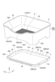
- FIG. 1 is a perspective view of a system toilet for pets according to one embodiment.
- FIG. 2 is an exploded perspective view of the pet toilet system of FIG. 1.
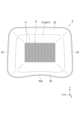
- FIG. 2 is a top view of the upper container of the pet toilet system of FIG. 1.
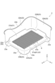
- 2 is a perspective view of the upper container of the pet system toilet of FIG. 1 as seen from the bottom side.
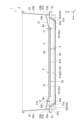
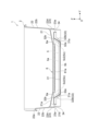
- FIG. 2 is a cross-sectional view of the pet toilet system taken along line V-V in FIG. 1 .
- 6 is a cross-sectional view of the pet toilet system taken along line VI-VI in FIG. 1.
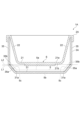
- FIG. 11 is a schematic cross-sectional view showing the configuration of a system toilet for pets according to a first modified example.
- 13A is a perspective view of a system toilet for pets according to a second modified example, and FIG.
- FIG. 13B is a perspective view of a lower container of the system toilet for pets of FIG. 13 is a partial cross-sectional view showing a fitting portion between an upper container and a lower container in a system toilet for pets according to a second modified example.
- FIG. 11 is a plan view showing an example of the configuration of a corner of the lower container.
- an upper container having a bottom wall portion provided with a liquid passage portion having a plurality of openings; a lower container disposed below the upper container so as to overlap the upper container, the lower container having a placement surface on which a pet sheet that absorbs the liquid that has passed through the liquid passing portion is placed; the lower container has a sheet placement portion connected to an outer edge of the placement surface and for placing the pet sheet along the edge of the pet sheet; In the system toilet for pets, an uppermost portion of the sheet placement portion is located above a lowermost portion of the liquid passing portion.
- the pet sheet is set in the lower container so that the edge of the pet sheet is aligned with the sheet placement section.
- the top of the sheet placement section is located higher than the bottom of the liquid passing section (i.e., the section that allows urine to fall into the lower container through multiple openings) of the bottom wall of the upper container, so it is possible to make the height position of the edge of the pet sheet reach a position higher than the bottom of the liquid passing section.
- urine that falls from the liquid passing section is less likely to leak outside the pet sheet.
- the distance between the pet sheet that has absorbed and expanded and the liquid passing section can be suitably reduced, which promotes the transfer of urine from the liquid passing section to the pet sheet. As a result, the amount of urine that remains unabsorbed in the pet sheet can be reduced, and the generation of bad odors can be suppressed.
- the liquid guide section can effectively transfer (drop) urine into the lower container. Furthermore, by setting the height position of the top of the sheet placement section at a position higher than the top of the arch section of the liquid guide section (the part that is most recessed at the top), the effect of suppressing urine leakage to the outside of the pet sheet can be further enhanced.
- the urine that falls from the liquid passage into the lower container can be guided to as central a position as possible of the pet sheet, which further enhances the effect of preventing urine leakage to the outside of the pet sheet.
- the granular material when granular material such as litter is placed on the bottom wall of the upper container, the granular material can be properly supported in the liquid passage while allowing only urine to pass through to the lower container.
- an upper surface of the liquid passing portion is continuous with an upper surface of a portion of the bottom wall portion where the liquid passing portion is not provided,
- the lowest part of the liquid passing portion can be effectively brought closer to the pet sheet placed on the placement surface of the lower container. This makes it possible to realize a configuration in which the top of the sheet placement portion is positioned above the bottom of the liquid passing portion, without making the height of the sheet placement portion significantly higher.
- the upper container has a first wall portion extending upward from an edge portion of the bottom wall portion, the seat placement portion has a second wall portion extending upward from an edge portion of the placement surface,
- the system toilet for pets according to any one of aspects 1 to 9, wherein the inner surface of the second wall portion is located more inward than the outer surface of the first wall portion.
- the lower container is housed below the upper container, and the width dimension of the lower container can be made smaller than the width dimension of the upper container, making it possible to make the pet toilet system compact.
- the upper container has a support wall portion supported on a floor surface and arranged to surround the lower container, a third wall portion constituting at least one surface of the support wall portion is provided with a recess portion that forms a space between the third wall portion and the floor surface,
- the lower container has a handle portion disposed at a position corresponding to the recess,
- the upper container alone can be easily lifted upward by grasping the bottom surface of the upper container located outside the handle (e.g., the inner surface of the recess in the third wall portion).
- This type of removal structure reduces the risk of the pet sheet getting caught on the upper container and being damaged when replacing the sheet.
- there is no need to slide the upper container laterally relative to the lower container so even if the top of the sheet placement portion is positioned to a certain degree, interference between the liquid passing portion and the sheet placement portion can be avoided when replacing the sheet, etc.
- the first part of the upper container is aligned with the second part of the lower container, making it easy to correctly install the upper container relative to the lower container.
- the positional relationship between the liquid passage part of the upper container and the sheet placement part of the lower container can be appropriately maintained, so that urine leakage to the outside of the sheet placement part (i.e., the outside of the pet sheet) can be suitably suppressed.
- the placement surface of the lower container has a substantially rectangular shape in a plan view
- the lower container has a pair of first side wall portions extending upward from an outer edge of the mounting surface on both sides in a first direction perpendicular to a vertical direction and along a second direction perpendicular to the vertical direction and the first direction, and a pair of second side wall portions extending upward from an outer edge of the mounting surface on both sides in the second direction and along the first direction
- a pet system toilet of any of aspects 1 to 12 wherein at each of the four corners of the mounting surface, a first displacement portion is formed at the second direction end of the first side wall portion, configured so that the first side wall portion is displaced outward in the first direction as it moves outward in the second direction, and a second displacement portion is formed at the first direction end of the second side wall portion, configured so that the second side wall portion is displaced outward in the second direction as it moves outward in the first direction.
- the first displacement portion and the second displacement portion can mitigate the bending actions applied from the first and second directions to the corners of the pet sheet located at the corners where the first and second side wall portions of each of the four corners of the placement surface intersect. This can prevent the corners of the pet sheet from standing up, and prevent gaps from occurring between the pet sheet and the corners of the lower container. As a result, urine leakage to the outside of the pet sheet placed on the lower container can be more effectively prevented.
- System toilet 1 is a toilet device for animals.
- An example of an animal that uses system toilet 1 is a cat, but the animals that use system toilet 1 are not limited to any particular animal.
- the up-down direction is represented as the Z-axis direction
- the longitudinal direction of system toilet 1 is represented as the X-axis direction
- the transverse direction of system toilet 1 is represented as the Y-axis direction.
- the above directions correspond to the XYZ Cartesian coordinate system shown in the drawings, and the up-down direction is represented as the "up-down direction Z", the longitudinal direction is represented as the “longitudinal direction X”, and the transverse direction is represented as the "transverse direction Y”.
- the system toilet 1 includes an upper container 2 and a lower container 3.
- the upper container 2 is a box-shaped container in which multiple granular objects (not shown), such as cat litter, are placed.
- the lower container 3 is a box-shaped container that is disposed below the upper container 2 so as to overlap with the upper container 2 in the vertical direction Z, and in which a pet sheet 5 (see FIG. 5 and FIG. 6) is placed.
- the length of the lower container 3 in the vertical direction Z is shorter than the length of the upper container 2 in the vertical direction Z.
- the upper container 2 has a bottom wall portion 21, a side wall portion 22 (first wall portion) connected to the edge of the bottom wall portion 21 and extending upward from said edge, and a support wall portion 23 connected to the edge of the bottom wall portion 21 and extending downward from said edge.
- the bottom wall portion 21 is formed in a generally rectangular shape in a plan view seen from the vertical direction Z, with the length in the longitudinal direction X being longer than the length in the lateral direction Y.
- the bottom wall portion 21 has an upper surface 21a facing upward and a lower surface 21b facing downward.
- a generally rectangular liquid passage portion 6 is formed in approximately the center of the bottom wall portion 21.
- the liquid passage section 6 is an area in which a plurality of openings H are formed, each penetrating in the vertical direction Z.
- a plurality of openings H (340 in this embodiment) are arranged in the liquid passage section 6, such that 10 openings H are lined up in the longitudinal direction X and 34 openings H are lined up in the lateral direction Y.
- Each opening H has a substantially rectangular shape whose length in the longitudinal direction X is longer than its length (width) in the lateral direction Y.
- the width (length in the lateral direction Y) of each opening H is, for example, 2.5 mm or less.
- the liquid passage section 6 appropriately supports the granular matter while allowing only urine (liquid) to pass through to the lower container 3 side.
- the upper surface 21a of the liquid passage section 6 i.e., the upper surface of the portion of the liquid passage section 6 where the opening H is not provided
- the lower surface 21b of the liquid passage section 6 i.e., the lower surface of the portion of the liquid passage section 6 where the opening H is not provided
- the lower surface 21b side of the liquid passage section 6 is provided with a plurality of bars 61 formed in a lattice shape so as to protrude downward from the lower surface 21b of the portion where the liquid passage section 6 is not provided, and arranged between the plurality of openings H.
- Each bar 61 extends in the longitudinal direction X and is provided on both sides of each opening H in the lateral direction Y.
- the lower surface 21b of the liquid passage section 6 is formed by the lower surface 61a of each of the plurality of bars 61.
- the liquid guide portion 62 is formed on the lower surface 21b of the liquid passage portion 6, in which multiple upwardly facing arc-shaped arch portions 63 are formed in succession.
- the liquid guide portion 62 is a portion configured to suitably guide urine passing through the multiple openings H from the upper surface 21a side to the lower surface 21b side.
- the arch portion 63 is formed by forming the center portion of the lower surface 61a of each crosspiece 61 in an upwardly concave arc shape. That is, each arch portion 63 is formed by the lower surface 61a of each crosspiece 61.
- a recess 22a is provided in a portion of the side wall 22 corresponding to one side (in this embodiment, one side extending in the longitudinal direction X) that functions as an entrance for allowing an animal to enter the interior of the upper container 2.
- the recess 22a also functions as an exit for allowing an animal to exit from the interior of the upper container 2.
- the side wall 22 may also have a function for arranging a member (e.g., a shovel) for putting in or scooping up multiple granular objects placed in the upper container 2.
- the upper end of the side wall 22 may be configured to have a shape and thickness that allows a protrusion (locking portion) provided on the handle portion of the above-mentioned member to be hooked.
- a case or the like for storing the above-mentioned member may be attached to the outer surface 22b or the like of the side wall 22.
- the lower container 3 has a placement surface 31, a side wall portion 32 (sheet placement portion, second wall portion), a pair of handle portions 33, and a pair of handle portions 34.
- the placement surface 31 is the surface on which the pet sheet 5 is placed, which absorbs urine that has passed through the liquid passage portion 6.
- the placement surface 31 is positioned opposite the bottom wall portion 21 of the upper container 2 so as to overlap in the vertical direction Z with the entire liquid passage portion 6 provided on the bottom wall portion 21.
- the side wall portion 32 is connected to the outer edge portion 31a of the placement surface 31 and extends upward from the outer edge portion 31a.
- the side wall portion 32 functions as a sheet placement portion along which the edge portion of the pet sheet 5 is placed.
- the side wall portion 32 is composed of a pair of side wall portions 32A facing each other in the longitudinal direction X, and a pair of side wall portions 32B facing each other in the lateral direction Y.
- the side wall portions 32A and 32B adjacent to each other at the corners are integrally formed so as to be continuous with each other.
- the pair of handles 33 are provided at approximately the center in the short direction Y of a pair of side wall portions 32A that face each other in the longitudinal direction X. Each handle portion 33 extends outward in the longitudinal direction X from the top portion 32b of each side wall portion 32A.
- the pair of handles 34 are provided at approximately the center in the longitudinal direction X of a pair of side wall portions 32B that face each other in the lateral direction Y. Each handle portion 34 extends outward in the lateral direction Y from the top portion 32b of each side wall portion 32B.
- the outline of the pet sheet 5 placed on the lower container 3 is shown by a dashed line.
- the pet sheet 5 is formed in a substantially rectangular shape larger than the placement surface 31 in a plan view, and has a liquid-permeable top sheet 5a (a sheet placed on the upper side when placed on the lower container 3), a back sheet 5b (a sheet placed on the lower side when placed on the lower container 3), and an absorbent (not shown) placed between the top sheet 5a and the back sheet 5b.
- the absorbent includes an absorbent core containing pulp, SAP, etc. for absorbing urine, and is placed in the substantially central part of the pet sheet 5 in a plan view.
- a flap part 5c is formed which is thinner than the substantially central part of the pet sheet 5 where the absorbent is placed, and can be easily folded along the edge of the absorbent.
- the pet sheet 5 is placed on the lower container 3 so that a pair of flap portions 5c1 (flap portions 5c provided on a pair of sides of the pet sheet 5 facing the longitudinal direction X) extending along the short-side direction Y of the pet sheet 5 are aligned with the inner surfaces 32a of a pair of side walls 32A.
- the pet sheet 5 is placed on the lower container 3 so that a pair of flap portions 5c2 (flap portions 5c provided on a pair of sides of the pet sheet 5 facing the short-side direction Y) extending along the longitudinal direction X of the pet sheet 5 are aligned with the inner surfaces 32a of a pair of side walls 32B.
- the inner surfaces 32a of the side walls 32A and 32B are configured as inclined surfaces that are inclined with respect to the vertical direction Z.
- the inner surfaces 32a of the side walls 32A and 32B may be formed in a curved shape or may be formed approximately parallel to the vertical direction Z.
- the side walls 32A, 32B are provided on the lower container 3, and the pet sheet 5 (in this embodiment, the flap portion 5c) is arranged along the inner surface 32a of the side walls 32A, 32B, so that the maximum height position of the pet sheet 5 placed on the lower container 3 can reach the top 32b, which is the uppermost part of the side walls 32A, 32B.
- the top 32b of the side walls 32A, 32B is located above the bottom part of the liquid passing section 6 (in this embodiment, the bottom surface 61a of the portion 61b between adjacent bars 61 in the longitudinal direction X).
- the maximum height position of the pet sheet 5 is configured to be able to reach above the bottom part of the liquid passing section 6.
- the pet sheet 5 is set in the lower container 3 so that the edge of the pet sheet 5 (in this embodiment, the flap portion 5c) is aligned with the side wall portions 32A, 32B (sheet placement portion).
- the uppermost portion (top portion 32b) of the side wall portions 32A, 32B is located above the lowermost portion (lower surface 61a of portion 61b) of the liquid passing portion 6 (i.e., the portion that allows urine to fall into the lower container 3 through the multiple openings H) of the bottom wall portion 21 of the upper container 2, so that the height position of the edge of the pet sheet 5 can reach a position higher than the lowermost portion of the liquid passing portion 6.
- the distance in the vertical direction Z between the bottom of the liquid passing section 6 and the pet sheet 5 (pet sheet 5 that has absorbed liquid and expanded) placed on the lower container 3 can be suitably reduced (or brought into contact), which promotes the transfer of urine from the liquid passing section 6 to the pet sheet 5.
- the amount of urine that remains unabsorbed in the pet sheet 5 can be reduced, and the generation of bad odors can be suppressed.
- system toilet 1 can be used by simply placing the upper container 2 on top of the lower container 3. This eliminates the need to pull out the tray when replacing the pet sheet 5, as was necessary with conventional pet system toilets that use a pull-out tray. This prevents the pet sheet 5 from getting caught on the upper container 2 or the like and causing unintended tearing or deformation when replacing the sheet, and also prevents urine leakage caused by these.
- the lower surface 21b of the liquid passage section 6 is provided with a liquid guide section 62 formed by multiple continuous upwardly facing arc-shaped arch sections 63 (lower surface 61a of the crosspiece 61).
- the apex 32b of the side wall sections 32A, 32B is located above the top of the arch section 63 (i.e., the approximately central part of the arch section 63 (lower surface 61a of the crosspiece 61) that is recessed most upwardly).
- the liquid guide section 62 can effectively transfer (drop) urine into the lower container 3.
- the height position of the top of the side wall sections 32A, 32B is set at a position higher than the top of the arch section 63 of the liquid passage section 62 (the part that is recessed most upwardly), which further enhances the effect of suppressing urine leakage to the outside of the pet sheet 5.
- the area of the liquid passing portion 6 (i.e., the area of the area occupied by the liquid passing portion 6 when viewed from the vertical direction Z) is smaller than the area of the placement surface 31, and the outer edge of the side walls 32A, 32B (the outermost part of the side walls 32A, 32B, the top 32b in this embodiment) is located outside the outer edge 6a of the liquid passing portion 6.
- the outer edge 31a of the mounting surface 31 (the edge to which the lower ends of the side walls 32A, 32B are connected) is located outside the outer edge 6a of the liquid passing portion 6.
- the liquid passing portion 6 is located inside the area where the flap portion 5c of the pet sheet 5 is located (the inner surface 32a of the side walls 32A, 32B).
- the distance d (see FIG. 5) between the bottom of the liquid passing portion 6 and the placement surface 31 is 25 mm or less.
- the thickness t1 of the liquid passing portion 6 (see FIG. 5) is greater than the thickness t2 of the portion of the bottom wall 21 where the liquid passing portion 6 is not provided (see FIG. 5).
- the thickness t1 of the liquid passing portion 6 is 5 mm or more. According to the above configuration, by making the portion of the bottom wall 21 where the liquid passing portion 6 is provided thicker than the other portions, it is possible to suppress bending of the liquid passing portion 6 and more effectively promote the transfer of urine from the liquid passing portion 6 to the pet sheet 5.
- the upper surface 21a of the liquid passing portion 6 is continuous with the upper surface 21a of the bottom wall portion 21 where the liquid passing portion 6 is not provided.
- the lower surface 21b of the liquid passing portion 6 protrudes downward from the lower surface 21b of the bottom wall portion 21 where the liquid passing portion 6 is not provided. That is, as described above, the lower surface 21b of the liquid passing portion 6 has a plurality of bars 61 protruding downward. According to the above configuration, by protruding the liquid passing portion 6 downward, the lowermost portion (portion 61b) of the liquid passing portion 6 can be effectively brought closer to the pet sheet 5 placed on the placement surface 31 of the lower container 3. This makes it possible to realize a configuration in which the tops 32b of the side walls 32A and 32B are located above the lowermost portion (portion 61b) of the liquid passing portion 6 without increasing the height of the side walls 32A and 32B significantly.
- the inner surface 32a of the side wall portions 32A, 32B is located inside the outer surface 22b of the side wall portion 22 of the upper container 2.
- the system toilet 1 is not configured to house the upper container 2A inside the lower container 3A like the system toilet 1A of the first modified example described below, but rather has a configuration in which the entire lower container 3 is housed in the space below the upper container 2. This allows the width dimension (lengthwise direction X or widthwise direction Y dimension) of the lower container 3 to be smaller than the width dimension of the upper container 2, making it possible to make the system toilet 1 compact.
- the upper container 2 has a support wall portion 23 that is supported on the floor surface and is arranged to surround the lower container 3.
- a recess 23a that forms a space between the floor surface and a portion constituting at least one surface of the support wall portion 23 (the third wall portion; in this embodiment, four portions corresponding to all surfaces) is provided.
- the lower container 3 has a pair of handle portions 34 that are arranged at positions corresponding to the recess 23a provided in the portion 23A of the support wall portion 23 along the longitudinal direction X. As shown in Figures 1 and 6, the entirety of each handle portion 34 is arranged inside the portion 23A in the short direction Y.
- the upper container 2 alone can be easily lifted upward by grasping the bottom surface of the upper container 2 located outside the handle (handle portion 34) (for example, the inner surface of the recess 23a of the portion 23A).
- This removal structure reduces the risk of the pet sheet 5 getting caught on the upper container 2 and being damaged when replacing the sheet.
- a part (including an outer end) of the pair of handle parts 33 arranged at a position corresponding to the recess 23a provided in the part 23B along the short side direction Y of the support wall part 23 is arranged outside the part 23B in the longitudinal direction X. Therefore, a user of the system toilet 1 can easily carry the upper container 2 together with the lower container 3 by lifting the pair of handle parts 33.
- the pair of handle parts 33 arranged to face each other in one direction are configured to protrude outside the support wall part 23 (part 23B), and the pair of handle parts 34 arranged to face each other in a direction intersecting the one direction (short side direction Y) are configured not to protrude outside the support wall part 23 (part 23A), thereby improving the convenience of the user. That is, when removing the upper container 2 from the lower container 3 (i.e., when lifting only the upper container 2), the user can easily lift only the upper container 2 by inserting his/her hands into the part where the pair of handle parts 34 are provided (the part outside the pair of handle parts 34). On the other hand, if you wish to carry the entire system toilet 1 (i.e., the upper container 2 and the lower container 3), you can easily carry the entire system toilet 1 by lifting the pair of handles 33.
- the shape of the handle portion of the lower container 3 is not limited to the configuration of this embodiment (i.e., a configuration including a pair of handle portions 33 provided so as to protrude outward from the support wall portion 23 (part 23B) and a pair of handle portions 34 provided so as not to protrude outward from the support wall portion 23 (part 23A).
- the pair of handle portions 33 may be provided so as not to protrude outward from the support wall portion 23 (part 23B), and the pair of handle portions 34 may be provided so as to protrude outward from the support wall portion 23 (part 23A).
- both of the handle portions 33, 34 may be provided so as to protrude outward from the support wall portion 23, or conversely, both of the handle portions 33, 34 (all of the four handle portions in total) may be provided so as not to protrude outward from the support wall portion 23.
- only one of the pair of handle portions 33 and the pair of handle portions 34 may be provided on the lower container 3.
- the pair of handles may be provided so as to protrude outward beyond the support wall portion 23, or may be provided so as not to protrude outward beyond the support wall portion 23.
- the lower container 3 may not be provided with handles.
- the upper container 2 when the upper container 2 is stacked on the lower container 3 to be used, it is easy to correctly install the upper container 2 relative to the lower container 3 by aligning the position of the first part of the upper container 2 (the recess 23a of part 23B) with the second part of the lower container 3 (the pair of handle parts 33).
- the positional relationship between the liquid passage 6 of the upper container 2 and the side walls 32A, 32B of the lower container 3 can be appropriately maintained, so urine leakage to the outside of the side walls 32A, 32B (i.e., the outside of the pet sheet 5) can be effectively prevented.
- the height (height from the placement surface 31) of the top (top 32b) of the above-mentioned sheet placement section (side wall section 32 in this embodiment) can be measured using, for example, a ruler.
- the height of the bottom of the liquid passing section 6 from the placement surface 31 can also be measured using a ruler.
- the thickness of the liquid passing section 6 (length from the top to the bottom of the liquid passing section 6) is also measured using a similar method.
- the height of the bottom of the liquid passing section 6 from the placement surface 31 can be obtained by subtracting the thickness of the liquid passing section 6 from the first length measured as described above.
- the above measurement method is only an example, and each dimension may be measured using a method other than the above.
- the present disclosure is not limited to the above embodiment.
- the material and shape of each component are not limited to the above-mentioned material and shape, and various materials and shapes can be adopted.
- some of the components included in the above-mentioned embodiment may be changed or omitted, or other components may be added.
- the side wall portion 32 whose maximum height position (upper end) is located on the same plane is exemplified as an example of the sheet arrangement portion, but the upper end portion of the sheet arrangement portion does not necessarily have to be constant.
- the upper end surface of the sheet arrangement portion may be provided with a structure for fixing a part (e.g., a corner portion) of the pet sheet 5 (e.g., a hole portion for inserting the corner portion of the pet sheet 5 so as to be outside the lower container and hooking it).
- a part e.g., a corner portion
- a hole portion for inserting the corner portion of the pet sheet 5 so as to be outside the lower container and hooking it.
- the toilet system 1A is mainly different from the toilet system 1 in that the upper container 2A is disposed inside the lower container 3A.
- the lower container 3A is a box-shaped (bathtub-shaped) container.
- a side wall 35 including a portion 35a (sheet disposition portion) along which the edge of the pet sheet 5 (e.g., the flap portion 5c) is aligned extends upward from the outer edge of the mounting surface 31.
- the upper container 2A is configured to be supported by the lower container 3A in a state in which the bottom wall 21 is disposed at a position spaced above the mounting surface 31 of the lower container 3A by being hooked on the upper end of the side wall 35 of the lower container 3A.
- the bottom wall 21 of the upper container 2A is provided with a liquid passage portion 6 similar to the bottom wall 21 of the upper container 2 described above.
- the configuration for supporting the upper container 2A by the lower container 3A is not limited to the example of FIG. 7.
- a support base e.g., a portion formed integrally with a portion of the side wall portion 35 and protruding inward
- a support base for supporting a portion of the bottom wall portion 21 of the upper container 2A may be provided inside the lower container 3A.
- portion 35a of the side wall 35 of the lower container 3A is a portion of the side wall 35 that has an inclined surface that is inclined to align with the edge of the pet sheet 5.
- the inclined surface may be formed in a curved shape.
- portion 35a is a portion of the side wall 35 intended to align with the edge of the pet sheet 5, and it is sufficient that the portion is configured to be distinguishable from other portions of the side wall 35 by a sudden change in curvature, etc.
- the portion of the side wall 35 above portion 35a configured as an inclined surface is formed to extend approximately parallel to the vertical direction.
- the top 35b of portion 35a is defined as the upper end of the inclined surface (i.e., the boundary between the portion that extends upward from the edge of the placement surface 31 at an incline with respect to the vertical direction and the portion that extends approximately parallel to the vertical direction).
- the uppermost part 35b (the part located on line L2 shown in FIG. 7) of the part 35a (sheet placement part) of the side wall part 35 of the lower container 3A is located above the lowermost part of the liquid passing part 6 (the part located on line L1 shown in FIG. 7).
- system toilet 1B A pet system toilet according to a second modification (hereinafter, referred to as "system toilet 1B") will be described with reference to Figs. 8 and 9.
- the system toilet 1B differs from the system toilet 1 in that the upper container 2B is more firmly fixed to the lower container 3B in the use state. More specifically, in the upper container 2B of the system toilet 1B, a horizontally elongated elliptical opening 23b is provided in the short direction Y instead of the recess 23a in the portion 23B of the support wall portion 23 facing the longitudinal direction X.
- a protrusion 36 is provided that protrudes outward from the side wall portion 32A so as to fit into the opening 23b.
- the protrusion 36 fits into the opening 23b of the portion 23B of the support wall portion 23.
- the engagement of the protrusion 36 with the opening 23b is released, and the upper container 2B can be pulled upward relative to the lower container 3B (i.e., the upper container 2B can be removed from the lower container 3B).
- the first part (opening 23b) of the upper container 2B and the second part (protrusion 36) of the lower container 3B are positioned and fixed (engaged) to each other, so that the lateral movement (longitudinal direction X and lateral direction Y) of the upper container 2B relative to the lower container 3B can be suppressed, and the movement in the vertical direction Z can also be suppressed.
- urine may accumulate on the support surface 31 of the lower container 3.
- a recess to facilitate the drainage of such urine may be provided in the side wall portion 32 of the lower container 3 (for example, the corner where the side wall portion 32A and the side wall portion 32B are connected).
- the mounting surface 31 of the lower container 3 has a substantially rectangular shape in a plan view (when viewed from the vertical direction Z).
- the lower container 3 has a pair of side walls 32A (first side walls) that rise upward from the outer edge 31a (outer edge along the short direction Y) of the mounting surface 31 on both sides of the longitudinal direction X (first direction) perpendicular to the vertical direction Z and are provided along the short direction Y (second direction), and a pair of side walls 32B (second side walls) that rise upward from the outer edge 31a (outer edge along the long direction X) of the mounting surface 31 on both sides of the short direction Y and are provided along the long direction X.
- the lower container 3 may further have the configuration shown in FIG. 10, based on the above configuration.
- FIG. 10 is a plan view of a portion including one corner of the lower container 3.
- a first displacement portion 32Aa is formed at the end of the side wall portion 32A in the short side direction Y, which is configured so that the side wall portion 32A (inner surface 32a) is displaced outward in the longitudinal direction X (to the left in the example of FIG. 10) as it moves outward in the short side direction Y (to the upper direction in the example of FIG.
- a second displacement portion 32Ba is formed at the end of the side wall portion 32B in the longitudinal direction X, which is configured so that the side wall portion 32B (inner surface 32a) is displaced outward in the short side direction Y as it moves outward in the longitudinal direction X.
- the first displacement portion 32Aa and the second displacement portion 32Ba can mitigate the bending action applied in the longitudinal direction X and the lateral direction Y to the corners of the pet sheet located at the corners C where the side wall portions 32A and 32B at each of the four corners of the placement surface 31 intersect. This can prevent the corners of the pet sheet from standing up, and prevent gaps from occurring between the pet sheet and the corners C of the lower container 3. As a result, urine leakage to the outside of the pet sheet placed on the lower container 3 can be more effectively prevented.
Landscapes
- Life Sciences & Earth Sciences (AREA)
- Environmental Sciences (AREA)
- Animal Husbandry (AREA)
- Biodiversity & Conservation Biology (AREA)
- Zoology (AREA)
- Housing For Livestock And Birds (AREA)
Abstract
一実施形態のシステムトイレ1は、複数の開口部Hを有する液通過部6が設けられた底壁部21を有する上容器2と、上容器2と重なるように上容器2の下方に配置され、液通過部6を通過した液体を吸収するペットシート5が載置される載置面31を有する下容器3と、を備える。下容器3は、載置面31の外縁部31aに接続され、ペットシート5の縁部を沿わせて配置するための側壁部32を有し、側壁部32の頂部32bは、液通過部6の最下部よりも上方に位置する。
Description
本開示は、ペット用システムトイレに関する。
ペット用システムトイレとして、尿が下方に通過する複数の穴が設けられた上容器と、上容器の下方に配置され、長手方向の前面に差し込み口が形成された下容器と、差し込み口から下容器内に収容されるトレーと、トレーの底面に載置されて、上容器の複数の穴から落下する尿を受け止めて吸収するペットシート(吸収性シート)と、を備える構成が知られている(例えば、特許文献1参照)。
上記のようなトレー引き出し型のシステムトイレでは、シート交換時にトレーを下容器内から引き出す際にペットシートが上容器に引っかかることを防止するために、上容器の底壁部(複数の穴が設けられた部分)とトレーとを十分に離す必要がある。しかし、上記のように上下方向における底壁部からペットシートまでの距離が長いと、上容器の複数の穴から落下する尿がペットシートの外側に漏れるおそれが高くなる。また、上容器の複数の穴から落下する尿がペットシートに移行し難くなるため、ペットシートに吸収されずに残る尿から悪臭が発生するおそれもある。
そこで、本開示の一側面は、ペットシートの外側への尿漏れ及び悪臭の発生を抑制することができるペット用システムトイレを提供することを目的とする。
本開示の一側面に係るペット用システムトイレは、複数の開口部を有する液通過部が設けられた底壁部を有する上容器と、上容器と重なるように上容器の下方に配置され、液通過部を通過した液体を吸収するペットシートが載置される載置面を有する下容器と、を備え、下容器は、載置面の外縁部に接続され、ペットシートの縁部を沿わせて配置するためのシート配置部を有し、シート配置部の最上部は、液通過部の最下部よりも上方に位置する。
本開示によれば、ペットシートの外側への尿漏れ及び悪臭の発生を抑制することができるペット用システムトイレを提供することができる。
本明細書及び添付図面の記載により、少なくとも以下の態様1~態様13が明らかとなる。
(態様1)
複数の開口部を有する液通過部が設けられた底壁部を有する上容器と、
前記上容器と重なるように前記上容器の下方に配置され、前記液通過部を通過した液体を吸収するペットシートが載置される載置面を有する下容器と、を備え、
前記下容器は、前記載置面の外縁部に接続され、前記ペットシートの縁部を沿わせて配置するためのシート配置部を有し、
前記シート配置部の最上部は、前記液通過部の最下部よりも上方に位置する、ペット用システムトイレ。
複数の開口部を有する液通過部が設けられた底壁部を有する上容器と、
前記上容器と重なるように前記上容器の下方に配置され、前記液通過部を通過した液体を吸収するペットシートが載置される載置面を有する下容器と、を備え、
前記下容器は、前記載置面の外縁部に接続され、前記ペットシートの縁部を沿わせて配置するためのシート配置部を有し、
前記シート配置部の最上部は、前記液通過部の最下部よりも上方に位置する、ペット用システムトイレ。
上記ペット用システムトイレでは、ペットシートの縁部がシート配置部に沿うように、ペットシートが下容器にセットされる。シート配置部の最上部は、上容器の底壁部の液通過部(すなわち、複数の開口部を介して尿を下容器側に落下させる部分)の最下部よりも上方に位置するため、ペットシートの縁部の高さ位置を液通過部の最下部よりも高い位置まで到達させることが可能となる。その結果、液通過部から落下した尿がペットシートの外側に漏れ難くなる。また、吸液して膨張したペットシートと液通過部との距離を好適に近づけることが可能となるため、液通過部からペットシートへと尿の移行を促進させることができる。その結果、ペットシートに吸収されずに残る尿の量を低減でき、悪臭の発生を抑制することができる。
(態様2)
前記液通過部の下面には、上方向に向く弧状のアーチ部が複数連続して形成された液誘導部が設けられており、
前記シート配置部の最上部は、前記アーチ部の最上部よりも上方に位置する、態様1のペット用システムトイレ。
前記液通過部の下面には、上方向に向く弧状のアーチ部が複数連続して形成された液誘導部が設けられており、
前記シート配置部の最上部は、前記アーチ部の最上部よりも上方に位置する、態様1のペット用システムトイレ。
態様2によれば、液誘導部によって、尿を下容器へと効果的に移行(落下)させることができる。さらに、シート配置部の最上部の高さ位置が液誘導部のアーチ部の最上部(最も上側に凹んだ部分)よりも高い位置に設定されていることにより、ペットシートの外側への尿漏れを抑制する効果をより一層高めることができる。
(態様3)
前記液通過部の面積は、前記載置面の面積よりも小さく、
前記シート配置部の外縁部は、前記液通過部の外縁部よりも外側に位置する、態様1又は2のペット用システムトイレ。
前記液通過部の面積は、前記載置面の面積よりも小さく、
前記シート配置部の外縁部は、前記液通過部の外縁部よりも外側に位置する、態様1又は2のペット用システムトイレ。
態様3によれば、液通過部から下容器へと落下する尿を、ペットシートのなるべく中央部に導くことができるため、ペットシートの外側への尿漏れを抑制する効果をより一層高めることができる。
(態様4)
前記液通過部の面積は、前記載置面の面積よりも小さく、
前記載置面の外縁部は、前記液通過部の外縁部よりも外側に位置する、態様1~3のいずれかのペット用システムトイレ。
前記液通過部の面積は、前記載置面の面積よりも小さく、
前記載置面の外縁部は、前記液通過部の外縁部よりも外側に位置する、態様1~3のいずれかのペット用システムトイレ。
態様4によれば、態様3について述べた効果をより一層高めることができる。
(態様5)
前記液通過部の最下部と前記載置面との距離は、25mm以下である、態様1~4のいずれかのペット用システムトイレ。
前記液通過部の最下部と前記載置面との距離は、25mm以下である、態様1~4のいずれかのペット用システムトイレ。
態様5によれば、ある程度の尿を吸収して膨張したペットシートの表面と液通過部の最下部とを接触(或いは近接)させることが可能となるため、液通過部からペットシートへの尿の移行を効果的に促進させることができる。その結果、悪臭の発生を好適に抑制することができる。
(態様6)
前記液通過部の厚さは、前記底壁部において前記液通過部が設けられていない部分の厚さよりも大きい、態様1~5のいずれかのペット用システムトイレ。
前記液通過部の厚さは、前記底壁部において前記液通過部が設けられていない部分の厚さよりも大きい、態様1~5のいずれかのペット用システムトイレ。
態様6によれば、底壁部のうち液通過部が設けられた部分を他の部分よりも厚くすることにより、液通過部の撓みを抑制し、液通過部からペットシートへの尿の移行をより一層効果的に促進させることができる。
(態様7)
前記液通過部の厚さは、5mm以上である、態様1~6のいずれかのペット用システムトイレ。
前記液通過部の厚さは、5mm以上である、態様1~6のいずれかのペット用システムトイレ。
態様7によれば、態様6について述べた効果をより一層高めることができる。
(態様8)
前記液通過部の前記開口部の幅は、2.5mm以下である、態様1~7のいずれかのペット用システムトイレ。
前記液通過部の前記開口部の幅は、2.5mm以下である、態様1~7のいずれかのペット用システムトイレ。
態様8によれば、上容器の底壁部の上にトイレ砂のような粒状物が配置される場合に、液通過部において当該粒状物を適切に支持しつつ、尿のみを下容器側に通過させることができる。
(態様9)
前記液通過部の上面は、前記底壁部において前記液通過部が設けられていない部分の上面と連続しており、
前記液通過部の下面は、前記底壁部において前記液通過部が設けられていない部分の下面よりも下方に突出している、態様1~8のいずれかのペット用システムトイレ。
前記液通過部の上面は、前記底壁部において前記液通過部が設けられていない部分の上面と連続しており、
前記液通過部の下面は、前記底壁部において前記液通過部が設けられていない部分の下面よりも下方に突出している、態様1~8のいずれかのペット用システムトイレ。
態様9によれば、液通過部を下方に突出させることにより、液通過部の最下部を下容器の載置面に載置されるペットシートに効果的に近づけることができる。これにより、シート配置部の高さをそれほど高くしなくても、シート配置部の最上部が液通過部の最下部よりも上方に位置する構成を実現することができる。
(態様10)
前記上容器は、前記底壁部の縁部から上方に延びる第1壁部を有し、
前記シート配置部は、前記載置面の縁部から上方に延びる第2壁部を有し、
前記第2壁部の内面は、前記第1壁部の外面よりも内側に位置している、態様1~9のいずれかのペット用システムトイレ。
前記上容器は、前記底壁部の縁部から上方に延びる第1壁部を有し、
前記シート配置部は、前記載置面の縁部から上方に延びる第2壁部を有し、
前記第2壁部の内面は、前記第1壁部の外面よりも内側に位置している、態様1~9のいずれかのペット用システムトイレ。
態様10によれば、上容器の下方に下容器が収容されると共に、下容器の幅寸法を上容器の幅寸法よりも小さくすることができるため、ペット用システムトイレをコンパクト化することができる。
(態様11)
前記上容器は、床面に支持されて前記下容器を包囲するように配置される支持壁部を有し、
前記支持壁部の少なくとも一つの面を構成する第3壁部には、前記床面との間に空間を形成する凹部が設けられており、
前記下容器は、前記凹部に対応する位置に配置される取手部を有し、
前記取手部の全体は、前記第3壁部よりも内側に配置される、態様1~10のいずれかのペット用システムトイレ。
前記上容器は、床面に支持されて前記下容器を包囲するように配置される支持壁部を有し、
前記支持壁部の少なくとも一つの面を構成する第3壁部には、前記床面との間に空間を形成する凹部が設けられており、
前記下容器は、前記凹部に対応する位置に配置される取手部を有し、
前記取手部の全体は、前記第3壁部よりも内側に配置される、態様1~10のいずれかのペット用システムトイレ。
態様11によれば、取手の外側に位置する上容器の底面(例えば、第3壁部の凹部の内面)を掴むことによって、上容器だけを容易に上方に持ち上げることができる。このような取り外し構造により、シート交換時に、ペットシートが上容器に引っかかって破損するリスクを低減できる。また、上記取り外し構造によれば、上容器を下容器に対して横方向にスライドさせる必要がないため、シート配置部の最上部の位置をある程度高くしたとしても、シート交換時等に液通過部とシート配置部とが干渉することを回避できる。
(態様12)
前記下容器に前記上容器が重ねられた使用状態において、前記上容器の第1部分と前記下容器の第2部分とが互いに位置決めされることにより、前記下容器に対する前記上容器の横方向の移動が抑制されるように構成されている、態様1~11のいずれかのペット用システムトイレ。
前記下容器に前記上容器が重ねられた使用状態において、前記上容器の第1部分と前記下容器の第2部分とが互いに位置決めされることにより、前記下容器に対する前記上容器の横方向の移動が抑制されるように構成されている、態様1~11のいずれかのペット用システムトイレ。
態様12によれば、上容器を下容器の上に重ねて使用状態にする際に、下容器の第2部分に対して上容器の第1部分の位置を合わせることにより、下容器に対して上容器を正しく設置することが容易となる。その結果、使用状態において、上容器の液通過部と下容器のシート配置部との位置関係を適切に維持することができるため、シート配置部の外側(すなわち、ペットシートの外側)への尿漏れを好適に抑制することができる。
(態様13)
前記下容器の前記載置面は、平面視において略矩形状を有しており、
前記下容器は、上下方向に直交する第1方向の両側において前記載置面の外縁部から上方に立ち上がりつつ前記上下方向及び前記第1方向に直交する第2方向に沿って設けられた一対の第1側壁部と、前記第2方向の両側において前記載置面の外縁部から上方に立ち上がりつつ前記第1方向に沿って設けられた一対の第2側壁部と、を有し、
前記載置面の四隅の各々において、前記第1側壁部の前記第2方向の端部には、前記第2方向の外側に向かうにつれて前記第1側壁部が前記第1方向の外側に変位するように構成された第1変位部が形成されていると共に、前記第2側壁部の前記第1方向の端部には、前記第1方向の外側に向かうにつれて前記第2側壁部が前記第2方向の外側に変位するように構成された第2変位部が形成されている、態様1~12のいずれかのペット用システムトイレ。
態様13によれば、下容器上にペットシートが載置された際に、載置面の四隅の各々の第1側壁部と第2側壁部とが交差する隅部に配置される当該ペットシートの角部に対して第1方向及び第2方向から付与される各折り曲げ動作を、第1変位部及び第2変位部によって緩和することができる。これにより、当該ペットシートの角部が起立することを抑制し、ペットシートと下容器の隅部との間の隙間が生じることを抑制することができる。その結果、下容器上に載置されたペットシートの外側への尿漏れをより一層効果的に抑制することができる。
[実施形態]
以下、本開示の実施形態について、図面を参照しつつ詳細に説明する。なお、以下の説明において、同一又は相当要素には同一符号を用い、重複する説明を省略する。
以下、本開示の実施形態について、図面を参照しつつ詳細に説明する。なお、以下の説明において、同一又は相当要素には同一符号を用い、重複する説明を省略する。
図1~図6を参照して、一実施形態に係るペット用システムトイレ(以下、「システムトイレ1」という。)について説明する。システムトイレ1は、動物用のトイレ装置である。システムトイレ1を利用する動物の例としては猫が挙げられるが、システムトイレ1を利用する動物は、特定の動物に限定されない。図面においては、上下方向をZ軸方向と表し、システムトイレ1の長手方向をX軸方向と表し、システムトイレ1の短手方向をY軸方向と表している。以下、上記の各方向を図面に表されるXYZ直交座標系と対応させて、上下方向を「上下方向Z」、長手方向を「長手方向X」、短手方向を「短手方向Y」と表す。
図1に示されるように、システムトイレ1は、上容器2と、下容器3と、を備えている。上容器2は、猫砂等の図示しない複数の粒状物が載置される箱状の容器である。下容器3は、上容器2と上下方向Zに重なるように上容器2の下方に配置され、ペットシート5(図5及び図6参照)が載置される箱状の容器である。本実施形態では、下容器3の上下方向Zの長さは、上容器2の上下方向Zの長さよりも短い。
図1~図4に示されるように、上容器2は、底壁部21と、底壁部21の縁部に接続されて当該縁部から上方に延びる側壁部22(第1壁部)と、底壁部21の縁部に接続されて当該縁部から下方に延びる支持壁部23と、を有している。
底壁部21は、上下方向Zから見た平面視において、長手方向Xの長さが短手方向Yの長さよりも長い略矩形状に形成されている。底壁部21は、上方を向く上面21aと下方を向く下面21bとを有している。図3に示されるように、底壁部21の略中央部には、略矩形状の液通過部6が形成されている。
液通過部6は、それぞれ上下方向Zに貫通する複数の開口部Hが形成された領域である。本実施形態では、液通過部6において、長手方向Xに10個の開口部Hが並ぶと共に短手方向Yに34個の開口部Hが並ぶように、複数(本実施形態では、340個)の開口部Hが配置されている。各開口部Hは、長手方向Xの長さが短手方向Yの長さ(幅)よりも長い略矩形状の形状を有している。各開口部Hの幅(短手方向Yの長さ)は、例えば2.5mm以下である。これにより、底壁部21の上面21a上に載置される粒状物(例えばトイレ砂)が開口部Hをすり抜けて下方に落下することが適切に防止される。すなわち、液通過部6において当該粒状物を適切に支持しつつ、尿(液体)のみを下容器3側に通過させることができる。
液通過部6の上面21a(すなわち、液通過部6のうち開口部Hが設けられていない部分の上面)は、底壁部21において液通過部6が設けられていない部分(すなわち、液通過部6の周囲の部分)の上面21aと連続している。一方、液通過部6の下面21b(すなわち、液通過部6のうち開口部Hが設けられていない部分の下面)は、底壁部21において液通過部6が設けられていない部分の下面21bよりも下方に突出している。本実施形態では、図4に示されるように、液通過部6の下面21b側には、液通過部6が設けられていない部分の下面21bよりも下方に突出するようにスノコ状に形成され、複数の開口部Hの間に配置された複数の桟61が設けられている。各桟61は、長手方向Xに延在しており、短手方向Yにおける各開口部Hの両側に設けられている。液通過部6の下面21bは、複数の桟61の各々の下面61aによって構成されている。
図4及び図5に示されるように、液通過部6の下面21bには、上方向に向く弧状のアーチ部63が複数連続して形成された液誘導部62が形成されている。液誘導部62は、複数の開口部Hを通過する尿を上面21a側から下面21b側へと好適に誘導可能に構成された部分である。本実施形態では、各桟61の下面61aの中央部が上方に凹んだ弧状に形成されることにより、アーチ部63が形成されている。すなわち、各アーチ部63は、各桟61の下面61aによって構成されている。このような複数のアーチ部63が長手方向Xに連続して形成されることにより、長手方向Xに隣り合う2つのアーチ部63(隣り合う2つの桟61の下面61a)の間の部分61b(すなわち、アーチ部63の中央部よりも下方に突出した部分)に尿が集まり易くなる。その結果、当該部分61bに集まった尿が下方に落下し易くなる。
側壁部22のうち一辺に対応する部分(本実施形態では、長手方向Xに延在する一の辺部)には、動物を上容器2の内部に進入させるための進入口として機能する凹部22aが設けられている。凹部22aは、上容器2の内部から動物を退出させる退出口としても機能する。なお、側壁部22は、上容器2に載置される複数の粒状物を入れたり掬ったりするための部材(例えば、スコップ)を配置するための機能を有してもよい。例えば、側壁部22の上端部は、上記部材の持ち手部分に設けられた突出部(係止部)を引っ掛けることが可能な形状及び厚みを有するように構成されてもよい。或いは、側壁部22の外面22b等に、上記部材を収容するためのケース等が取り付けられてもよい。
図2、図4及び図5に示されるように、下容器3は、載置面31と、側壁部32(シート配置部、第2壁部)と、一対の取手部33と、一対の取手部34と、を有している。
載置面31は、液通過部6を通過した尿を吸収するペットシート5が載置される面である。載置面31は、上容器2の底壁部21に対向する位置において、底壁部21に設けられた液通過部6の全体と上下方向Zに重なるように配置される。
側壁部32は、載置面31の外縁部31aに接続され、当該外縁部31aから上方に延びる部分である。側壁部32は、ペットシート5の縁部を沿わせて配置するためのシート配置部として機能する。側壁部32は、長手方向Xに対向する一対の側壁部32Aと、短手方向Yに対向する一対の側壁部32Bと、によって構成されている。角部において隣り合う側壁部32Aと側壁部32Bとは、互いに連続するように一体的に形成されている。
一対の取手部33は、長手方向Xに対向する一対の側壁部32Aの短手方向Yにおける略中央部に設けられている。各取手部33は、各側壁部32Aの頂部32bから長手方向Xにおける外側に向かって延在している。
一対の取手部34は、短手方向Yに対向する一対の側壁部32Bの長手方向Xにおける略中央部に設けられている。各取手部34は、各側壁部32Bの頂部32bから短手方向Yにおける外側に向かって延在している。
図5及び図6において、下容器3上に載置されるペットシート5の輪郭を破線によって模式的に表している。一例として、ペットシート5は、平面視において、載置面31よりも大きい略矩形状に形成されており、液透過性の表面シート5a(下容器3上に載置された際に上側に配置されるシート)と、裏面シート5b(下容器3上に載置された際に下側に配置されるシート)と、表面シート5a及び裏面シート5bの間に配置される吸収体(不図示)と、を有している。吸収体は、尿を吸収するためのパルプ、SAP等を含む吸収性コアを含んでおり、平面視においてペットシート5の略中央部に配置される。ペットシート5のうち吸収体が配置されない部分(すなわち、ペットシート5の略中央部よりも外側の縁部)には、ペットシート5のうち吸収体が配置された略中央部よりも薄く、吸収体の縁部に沿って容易に折り曲げることが可能なフラップ部5cが形成されている。
本実施形態では、図5に示されるように、ペットシート5の短手方向Yに沿って延在する一対のフラップ部5c1(長手方向Xに対向するペットシート5の一対の辺部に設けられたフラップ部5c)が一対の側壁部32Aの内面32aに沿うように、ペットシート5が下容器3上に配置される。また、図6に示されるように、ペットシート5の長手方向Xに沿って延在する一対のフラップ部5c2(短手方向Yに対向するペットシート5の一対の辺部に設けられたフラップ部5c)が一対の側壁部32Bの内面32aに沿うように、ペットシート5が下容器3上に配置される。一例として、側壁部32A,32Bの内面32aは、上下方向Zに対して傾斜する傾斜面として構成されている。ただし、側壁部32A,32Bの内面32aは、曲面状に形成されてもよいし、上下方向Zに略平行に形成されてもよい。
このように、下容器3に側壁部32A,32Bが設けられ、ペットシート5(本実施形態では、フラップ部5c)が側壁部32A,32Bの内面32aに沿うように配置されることにより、下容器3に載置されるペットシート5の最大高さ位置を側壁部32A,32Bの最上部である頂部32bまで到達させることができる。また、図5及び図6に示されるように、上容器2と下容器3とを上下方向Zに重ねた使用状態において、側壁部32A,32Bの頂部32bは、液通過部6の最下部(本実施形態では、長手方向Xに隣り合う桟61の間の部分61bの下面61a)よりも上方に位置する。これにより、本実施形態では、ペットシート5の最大高さ位置を液通過部6の最下部よりも上方まで到達させることが可能に構成されている。
以下、システムトイレ1のいくつかの作用効果について説明する。システムトイレ1では、ペットシート5の縁部(本実施形態では、フラップ部5c)が側壁部32A,32B(シート配置部)に沿うように、ペットシート5が下容器3にセットされる。側壁部32A,32Bの最上部(頂部32b)は、上容器2の底壁部21の液通過部6(すなわち、複数の開口部Hを介して尿を下容器3側に落下させる部分)の最下部(部分61bの下面61a)よりも上方に位置するため、ペットシート5の縁部の高さ位置を液通過部6の最下部よりも高い位置まで到達させることが可能となる。その結果、液通過部6から落下した尿がペットシート5の外側に漏れ難くなる。また、このように構成することにより、液通過部6の最下部と下容器3に載置されたペットシート5(吸液して膨張したペットシート5)との上下方向Zの距離を好適に近づける(或いは接触させる)ことができるため、液通過部6からペットシート5への尿の移行を促進させることができる。その結果、ペットシート5に吸収されずに残る尿の量を低減でき、悪臭の発生を抑制することができる。
さらに、システムトイレ1では、単純に下容器3の上に上容器2に重ねて配置することで使用状態にすることができる。これにより、ペットシート5の交換時に、従来のトレー引き出し型のペット用システムトイレにおいて必要とされていたトレーを引き出す作業が発生しない。このため、シート交換時において、ペットシート5が上容器2等に引っかかって意図しない破れや変形が発生することを抑制でき、これらに起因する尿漏れの発生も回避できる。
さらに、システムトイレ1では、液通過部6の下面21bには、上方向に向く弧状のアーチ部63(桟61の下面61a)が複数連続して形成された液誘導部62が設けられている。また、図5に示されるように、側壁部32A,32Bの頂部32bは、アーチ部63の最上部(すなわち、アーチ部63(桟61の下面61a)の最も上方に凹んだ略中央部)よりも上方に位置する。上記構成によれば、液誘導部62によって、尿を下容器3へと効果的に移行(落下)させることができる。さらに、側壁部32A,32Bの最上部の高さ位置が液誘導部62のアーチ部63の最上部(最も上側に凹んだ部分)よりも高い位置に設定されていることにより、ペットシート5の外側への尿漏れを抑制する効果をより一層高めることができる。
図5及び図6に示されるように、液通過部6の面積(すなわち、上下方向Zから見た場合に液通過部6が占める領域の面積)は、載置面31の面積よりも小さく、側壁部32A,32Bの外縁部(側壁部32A,32Bのうち最も外側の部分であり、本実施形態では頂部32b)は、液通過部6の外縁部6aよりも外側に位置する。上記構成によれば、液通過部6から下容器3へと落下する尿を、ペットシート5のなるべく中央部(すなわち、吸収体が配置された領域)に導くことができるため、ペットシート5の外側への尿漏れを抑制する効果をより一層高めることができる。
さらに、システムトイレ1では、載置面31の外縁部31a(側壁部32A,32Bの下端部が接続される縁部)は、液通過部6の外縁部6aよりも外側に位置する。すなわち、液通過部6は、ペットシート5のフラップ部5cが配置される領域(側壁部32A,32Bの内面32a)よりも内側に配置されている。上記構成によれば、上述した効果(すなわち、液通過部6から下容器3へと落下する尿を、ペットシート5のなるべく中央部に導く効果)をより一層高めることができる。
一例として、液通過部6の最下部と載置面31との距離d(図5参照)は、25mm以下である。上記構成によれば、ある程度の尿を吸収して膨張したペットシート5の表面(表面シート5aの上面)と液通過部6の最下部(尿が集まり易い部分61b)とを接触(或いは近接)させることが可能となるため、液通過部6からペットシート5への尿の移行を効果的に促進させることができる。その結果、悪臭の発生を好適に抑制することができる。
液通過部6の厚さt1(図5参照)は、底壁部21において液通過部6が設けられていない部分の厚さt2(図5参照)よりも大きい。一例として、液通過部6の厚さt1は、5mm以上である。上記構成によれば、底壁部21のうち液通過部6が設けられた部分を他の部分よりも厚くすることにより、液通過部6の撓みを抑制し、液通過部6からペットシート5への尿の移行をより一層効果的に促進させることができる。
図5及び図6に示されるように、液通過部6の上面21aは、底壁部21において液通過部6が設けられていない部分の上面21aと連続している。一方、液通過部6の下面21bは、底壁部21において液通過部6が設けられていない部分の下面21bよりも下方に突出している。すなわち、上述したように、液通過部6の下面21bには、下方に突出する複数の桟61が形成されている。上記構成によれば、液通過部6を下方に突出させることにより、液通過部6の最下部(部分61b)を下容器3の載置面31に載置されるペットシート5に効果的に近づけることができる。これにより、側壁部32A,32Bの高さをそれほど高くしなくても、側壁部32A,32Bの頂部32bが液通過部6の最下部(部分61b)よりも上方に位置する構成を実現することができる。
図5及び図6に示されるように、側壁部32A,32Bの内面32aは、上容器2の側壁部22の外面22bよりも内側に位置している。すなわち、システムトイレ1は、後述する第1変形例のシステムトイレ1Aのように下容器3Aの内側に上容器2Aを収める構成ではなく、上容器2の下方のスペースに下容器3の全体が収容される構成を有している。これにより、下容器3の幅寸法(長手方向X又は短手方向Yの寸法)を上容器2の幅寸法よりも小さくすることができるため、システムトイレ1をコンパクト化することができる。
図1、図2及び図4~図6に示されるように、上容器2は、床面に支持されて下容器3を包囲するように配置される支持壁部23を有している。支持壁部23の少なくとも一つの面を構成する部分(第3壁部。本実施形態では、全ての面に対応する4つの部分)には、床面との間に空間を形成する凹部23aが設けられている。下容器3は、支持壁部23のうち長手方向Xに沿った部分23Aに設けられた凹部23aに対応する位置に配置される一対の取手部34を有している。図1及び図6に示されるように、各取手部34の全体は、部分23Aよりも短手方向Yの内側に配置される。上記構成によれば、取手(取手部34)の外側に位置する上容器2の底面(例えば、部分23Aの凹部23aの内面)を掴むことによって、上容器2だけを容易に上方に持ち上げることができる。このような取り外し構造により、シート交換時に、ペットシート5が上容器2に引っかかって破損するリスクを低減できる。また、上記取り外し構造によれば、上容器2を下容器3に対して横方向(上下方向Zに直交する方向)にスライドさせる必要がないため、側壁部32A,32Bの最上部(頂部32b)の位置をある程度高くしたとしても、シート交換時等に液通過部6と側壁部32A,32Bとが干渉することを回避できる。
なお、本実施形態では、支持壁部23のうち短手方向Yに沿った部分23Bに設けられた凹部23aに対応する位置に配置される一対の取手部33の一部(外側端部を含む部分)は、部分23Bよりも長手方向Xの外側に配置されている。このため、システムトイレ1のユーザは、一対の取手部33を持ち上げることにより、下容器3と共に上容器2を容易に持ち運ぶことができる。このように、一方向(長手方向X)に対向するように配置された一対の取手部33については支持壁部23(部分23B)よりも外側に突出するように構成し、上記一方向に交差する方向(短手方向Y)に対向するように配置された一対の取手部34については支持壁部23(部分23A)よりも外側に突出しないように構成することにより、ユーザの利便性を向上させることができる。すなわち、下容器3から上容器2を取り外す場合(すなわち、上容器2だけを持ち上げる場合)には、一対の取手部34が設けられた部分(一対の取手部34よりも外側の部分)に手を入れて上容器2だけを容易に持ち上げることができる。一方、システムトイレ1の全体(すなわち、上容器2及び下容器3)を持ち運びたい場合には、一対の取手部33を持ち上げることによって、システムトイレ1の全体を容易に持ち運ぶことができる。
なお、下容器3の取手部の形態は、本実施形態の構成(すなわち、支持壁部23(部分23B)よりも外側に突出するように設けられた一対の取手部33及び支持壁部23(部分23A)よりも外側に突出しないように設けられた一対の取手部34を備える構成)に限られない。例えば、本実施形態とは逆に、一対の取手部33が支持壁部23(部分23B)よりも外側に突出しないように設けられると共に、一対の取手部34が支持壁部23(部分23A)よりも外側に突出するように設けられてもよい。また、取手部33,34の両方(計4つの取手部の全て)が支持壁部23よりも外側に突出するように設けられてもよいし、それとは逆に、取手部33,34の両方(計4つの取手部の全て)が支持壁部23よりも外側に突出しないように設けられてもよい。また、下容器3には、一対の取手部33及び一対の取手部34のうちのいずれか一方の取手対(計2つの取手部)のみが設けられてもよい。この場合において、当該取手対は、支持壁部23よりも外側に突出するように設けられてもよいし、支持壁部23よりも外側に突出しないように設けられてもよい。また、後述する第2変形例(図8参照)のように、下容器3には取手部が設けられなくてもよい。
下容器3に上容器2が重ねられた使用状態(図1)において、上容器2の第1部分(本実施形態では、部分23Bの凹部23a)と下容器3の第2部分(本実施形態では、一対の取手部33)とが互いに位置決めされることにより、下容器3に対する上容器2の横方向(本実施形態では、少なくとも短手方向Y)の移動が抑制されるように構成されている。すなわち、本実施形態では、支持壁部23の部分23Bの凹部23aに取手部33の一部がはまり込むことにより、下容器3に対して上容器2がずれないように適切に位置決めされる。上記構成によれば、上容器2を下容器3の上に重ねて使用状態にする際に、下容器3の第2部分(一対の取手部33)に対して上容器2の第1部分(部分23Bの凹部23a)の位置を合わせることにより、下容器3に対して上容器2を正しく設置することが容易となる。その結果、使用状態において、上容器2の液通過部6と下容器3の側壁部32A,32Bとの位置関係を適切に維持することができるため、側壁部32A,32Bの外側(すなわち、ペットシート5の外側)への尿漏れを好適に抑制することができる。
なお、上述したシート配置部(本実施形態では、側壁部32)の最上部(頂部32b)の高さ(載置面31からの高さ)は、例えば定規等を用いて測定することができる。また、液通過部6の最下部の載置面31からの高さについても、同様に定規等を用いて測定することができる。ただし、液通過部6の最下部の載置面31からの高さを直接測定することが難しい場合には、例えば以下のように測定してもよい。すなわち、液通過部6の開口部Hの上方から定規を差し込むことにより、載置面31から液通過部6の最上部(上面21a)までの長さ(第1長さ)を測定する。また、液通過部6の厚さ(液通過部6の最上部から最下部までの長さ)についても、同様の方法によって測定する。上記のように測定された第1長さから液通過部6の厚さを差し引くことにより、液通過部6の最下部の載置面31からの高さを求めることができる。ただし、上記測定方法は一例であり、各寸法は上記とは異なる方法によって測定されてもよい。
[変形例]
以上、本開示の実施形態について説明したが、本開示は、上記実施形態に限られない。各構成の材料及び形状には、上述した材料及び形状に限らず、様々な材料及び形状を採用することができる。また、上述した実施形態の構成に含まれる一部の構成は、変更又は省略されてもよいし、他の構成が付加されてもよい。例えば、上記実施形態では、最大高さ位置(上端部)が同一平面上に位置する側壁部32をシート配置部の一例として例示したが、シート配置部の上端部は、必ずしも一定でなくてもよい。また、シート配置部(側壁部32)の上端面には、ペットシート5の一部(例えば角部)を固定するための構造(例えば、ペットシート5の角部を下容器の外側に出るように挿通させて引っ掛けるための孔部等)が設けられてもよい。以下、その他の具体的ないくつかの変形例について記載する。
以上、本開示の実施形態について説明したが、本開示は、上記実施形態に限られない。各構成の材料及び形状には、上述した材料及び形状に限らず、様々な材料及び形状を採用することができる。また、上述した実施形態の構成に含まれる一部の構成は、変更又は省略されてもよいし、他の構成が付加されてもよい。例えば、上記実施形態では、最大高さ位置(上端部)が同一平面上に位置する側壁部32をシート配置部の一例として例示したが、シート配置部の上端部は、必ずしも一定でなくてもよい。また、シート配置部(側壁部32)の上端面には、ペットシート5の一部(例えば角部)を固定するための構造(例えば、ペットシート5の角部を下容器の外側に出るように挿通させて引っ掛けるための孔部等)が設けられてもよい。以下、その他の具体的ないくつかの変形例について記載する。
(第1変形例)
図7を参照して、第1変形例に係るペット用システムトイレ(以下、「システムトイレ1A」という。)について説明する。システムトイレ1Aは、上容器2Aが下容器3Aの内側に配置される点において、システムトイレ1と主に相違している。下容器3Aは、箱状(バスタブ状)の容器である。下容器3Aでは、ペットシート5の縁部(例えばフラップ部5c)が沿う部分35a(シート配置部)を含む側壁部35が、載置面31の外縁部から上方に延びている。一例として、上容器2Aは、下容器3Aの側壁部35の上端部に引っ掛けられることにより、底壁部21が下容器3Aの載置面31よりも上方に離隔した位置に配置された状態で、下容器3Aに対して支持されるように構成されている。上容器2Aの底壁部21には、上述した上容器2の底壁部21と同様の液通過部6が設けられている。なお、下容器3Aに対して上容器2Aを支持する構成は、図7の例に限られない。例えば、下容器3Aの内側に上容器2Aの底壁部21の一部を支持するための支持台(例えば、側壁部35の一部と一体的に形成されて、内側に突出する部分)が設けられてもよい。
図7を参照して、第1変形例に係るペット用システムトイレ(以下、「システムトイレ1A」という。)について説明する。システムトイレ1Aは、上容器2Aが下容器3Aの内側に配置される点において、システムトイレ1と主に相違している。下容器3Aは、箱状(バスタブ状)の容器である。下容器3Aでは、ペットシート5の縁部(例えばフラップ部5c)が沿う部分35a(シート配置部)を含む側壁部35が、載置面31の外縁部から上方に延びている。一例として、上容器2Aは、下容器3Aの側壁部35の上端部に引っ掛けられることにより、底壁部21が下容器3Aの載置面31よりも上方に離隔した位置に配置された状態で、下容器3Aに対して支持されるように構成されている。上容器2Aの底壁部21には、上述した上容器2の底壁部21と同様の液通過部6が設けられている。なお、下容器3Aに対して上容器2Aを支持する構成は、図7の例に限られない。例えば、下容器3Aの内側に上容器2Aの底壁部21の一部を支持するための支持台(例えば、側壁部35の一部と一体的に形成されて、内側に突出する部分)が設けられてもよい。
一例として、下容器3Aの側壁部35の部分35aは、側壁部35のうち、ペットシート5の縁部を沿わせるために傾斜した傾斜面を有する部分である。傾斜面は曲面状に形成されてもよい。いずれにしても、部分35aは、側壁部35のうちペットシート5の縁部を沿わせることを意図した部分であり、曲率の急激な変化等によって側壁部35の他の部分と区別可能に構成された部分であればよい。図7の例では、側壁部35のうち傾斜面として構成された部分35aよりも上の部分は、上下方向に略平行に延びるように形成されている。この場合、部分35aの最上部35bは、傾斜面の上端部(すなわち、載置面31の縁部から上下方向に対して傾斜して上方に延びる部分と上下方向に略平行に延びる部分との境界部)として定義される。
システムトイレ1Aにおいても、システムトイレ1と同様に、上容器2Aと下容器3Aとを上下方向に重ねた使用状態において、下容器3Aの側壁部35の部分35a(シート配置部)の最上部35b(図7に示されるラインL2上に位置する部分)は、液通過部6の最下部(図7に示されるラインL1上に位置する部分)よりも上方に位置する。このような構成によっても、システムトイレ1と同様に、ペットシート5の最大高さ位置を液通過部6の最下部よりも上方まで到達させることが可能となるため、システムトイレ1と同様の効果(すなわち、液通過部6から落下した尿がペットシート5の外側に漏れ難くなると共に、液通過部6からペットシート5へと尿が移行し易くなる効果)が得られる。
(第2変形例)
図8及び図9を参照して、第2変形例に係るペット用システムトイレ(以下、「システムトイレ1B」という。)について説明する。システムトイレ1Bは、使用状態において、上容器2Bが下容器3Bに対してより強固に固定される点において、システムトイレ1と相違している。より具体的には、システムトイレ1Bの上容器2Bでは、支持壁部23のうち長手方向Xに対向する部分23Bにおいて、凹部23aの代わりに、短手方向Yに横長の楕円状の開口部23bが設けられている。また、システムトイレ1Bの下容器3Bには、一対の取手部33の代わりに、開口部23bに嵌合するように側壁部32Aの外側に突出する突出部36が設けられている。図9に示されるように、上容器2Bを下容器3Bの上方から下方に押し込むことにより、突出部36が支持壁部23の部分23Bの開口部23bに嵌合する。図9に示される状態から、突出部36の外面を矢印Aの方向に内側に押し込むことにより開口部23bに対する突出部36の嵌合が解除され、下容器3Bに対して上容器2Bを上方に引き上げる(すなわち、下容器3Bから上容器2Bを取り外す)ことが可能となる。システムトイレ1Bによれば、上容器2Bの第1部分(開口部23b)と下容器3Bの第2部分(突出部36)とが互いに位置決め及び固定(嵌合)されることにより、下容器3Bに対する上容器2Bの横方向(長手方向X及び短手方向Y)の移動を抑制できると共に、上下方向Zの移動も抑制できる。
図8及び図9を参照して、第2変形例に係るペット用システムトイレ(以下、「システムトイレ1B」という。)について説明する。システムトイレ1Bは、使用状態において、上容器2Bが下容器3Bに対してより強固に固定される点において、システムトイレ1と相違している。より具体的には、システムトイレ1Bの上容器2Bでは、支持壁部23のうち長手方向Xに対向する部分23Bにおいて、凹部23aの代わりに、短手方向Yに横長の楕円状の開口部23bが設けられている。また、システムトイレ1Bの下容器3Bには、一対の取手部33の代わりに、開口部23bに嵌合するように側壁部32Aの外側に突出する突出部36が設けられている。図9に示されるように、上容器2Bを下容器3Bの上方から下方に押し込むことにより、突出部36が支持壁部23の部分23Bの開口部23bに嵌合する。図9に示される状態から、突出部36の外面を矢印Aの方向に内側に押し込むことにより開口部23bに対する突出部36の嵌合が解除され、下容器3Bに対して上容器2Bを上方に引き上げる(すなわち、下容器3Bから上容器2Bを取り外す)ことが可能となる。システムトイレ1Bによれば、上容器2Bの第1部分(開口部23b)と下容器3Bの第2部分(突出部36)とが互いに位置決め及び固定(嵌合)されることにより、下容器3Bに対する上容器2Bの横方向(長手方向X及び短手方向Y)の移動を抑制できると共に、上下方向Zの移動も抑制できる。
また、その他様々な変形がされてもよい。例えば、ペットシート5で吸収可能な量を超える尿が上容器2から下容器3へと流れた場合には、下容器3の載置面31上に尿が溜まる場合がある。このような尿を容易に排出するための窪みが下容器3の側壁部32(例えば、側壁部32Aと側壁部32Bとが接続される角部)に設けられてもよい。
また、上記実施形態では、下容器3の載置面31は、平面視(上下方向Zから見た場合)において略矩形状を有している。また、下容器3は、上下方向Zに直交する長手方向X(第1方向)の両側において載置面31の外縁部31a(短手方向Yに沿った外縁部)から上方に立ち上がりつつ短手方向Y(第2方向)に沿って設けられた一対の側壁部32A(第1側壁部)と、短手方向Yの両側において載置面31の外縁部31a(長手方向Xに沿った外縁部)から上方に立ち上がりつつ長手方向Xに沿って設けられた一対の側壁部32B(第2側壁部)と、を有している。下容器3は、上記のような構成を前提として、図10に示される構成を更に備えてもよい。図10は、下容器3の一の隅部を含む部分の平面図である。図10に示されるように、載置面31の四隅の各々において、側壁部32Aの短手方向Yの端部には、短手方向Yの外側(図10の例では図示上方向)に向かうにつれて側壁部32A(内面32a)が長手方向Xの外側(図10の例では図示左方向)に変位するように構成された第1変位部32Aaが形成されていると共に、側壁部32Bの長手方向Xの端部には、長手方向Xの外側に向かうにつれて側壁部32B(内面32a)が短手方向Yの外側に変位するように構成された第2変位部32Baが形成されていてもよい。
図10に示した上記構成によれば、下容器3上にペットシートが載置された際に、載置面31の四隅の各々の側壁部32Aと側壁部32Bとが交差する隅部Cに配置されるペットシートの角部に対して長手方向X及び短手方向Yから付与される各折り曲げ動作を、第1変位部32Aa及び第2変位部32Baによって緩和することができる。これにより、当該ペットシートの角部が起立することを抑制し、ペットシートと下容器3の隅部Cとの間の隙間が生じることを抑制することができる。その結果、下容器3上に載置されたペットシートの外側への尿漏れをより一層効果的に抑制することができる。
1,1A,1B…システムトイレ(ペット用システムトイレ)、2,2A,2B…上容器、3,3A,3B…下容器、5…ペットシート、6…液通過部、6a…外縁部、21…底壁部、21a…上面、21b…下面、22…側壁部(第1壁部)、22b…外面、23…支持壁部、23a…凹部、31…載置面、31a…外縁部、32…側壁部(シート配置部)、32A…側壁部(シート配置部、第1側壁部)、32B…側壁部(シート配置部、第2側壁部)、32Aa…第1変位部、32Ba…第2変位部、32a…内面、33,34…取手部、35a…部分(シート配置部)、62…液誘導部、63…アーチ部、H…開口部。
Claims (13)
- 複数の開口部を有する液通過部が設けられた底壁部を有する上容器と、
前記上容器と重なるように前記上容器の下方に配置され、前記液通過部を通過した液体を吸収するペットシートが載置される載置面を有する下容器と、を備え、
前記下容器は、前記載置面の外縁部に接続され、前記ペットシートの縁部を沿わせて配置するためのシート配置部を有し、
前記シート配置部の最上部は、前記液通過部の最下部よりも上方に位置する、ペット用システムトイレ。 - 前記液通過部の下面には、上方向に向く弧状のアーチ部が複数連続して形成された液誘導部が設けられており、
前記シート配置部の最上部は、前記アーチ部の最上部よりも上方に位置する、請求項1に記載のペット用システムトイレ。 - 前記液通過部の面積は、前記載置面の面積よりも小さく、
前記シート配置部の外縁部は、前記液通過部の外縁部よりも外側に位置する、請求項1に記載のペット用システムトイレ。 - 前記液通過部の面積は、前記載置面の面積よりも小さく、
前記載置面の外縁部は、前記液通過部の外縁部よりも外側に位置する、請求項1に記載のペット用システムトイレ。 - 前記液通過部の最下部と前記載置面との距離は、25mm以下である、請求項1に記載のペット用システムトイレ。
- 前記液通過部の厚さは、前記底壁部において前記液通過部が設けられていない部分の厚さよりも大きい、請求項1に記載のペット用システムトイレ。
- 前記液通過部の厚さは、5mm以上である、請求項1に記載のペット用システムトイレ。
- 前記液通過部の前記開口部の幅は、2.5mm以下である、請求項1に記載のペット用システムトイレ。
- 前記液通過部の上面は、前記底壁部において前記液通過部が設けられていない部分の上面と連続しており、
前記液通過部の下面は、前記底壁部において前記液通過部が設けられていない部分の下面よりも下方に突出している、請求項1に記載のペット用システムトイレ。 - 前記上容器は、前記底壁部の縁部から上方に延びる第1壁部を有し、
前記シート配置部は、前記載置面の縁部から上方に延びる第2壁部を有し、
前記第2壁部の内面は、前記第1壁部の外面よりも内側に位置している、請求項1に記載のペット用システムトイレ。 - 前記上容器は、床面に支持されて前記下容器を包囲するように配置される支持壁部を有し、
前記支持壁部の少なくとも一つの面を構成する第3壁部には、前記床面との間に空間を形成する凹部が設けられており、
前記下容器は、前記凹部に対応する位置に配置される取手部を有し、
前記取手部の全体は、前記第3壁部よりも内側に配置される、請求項1に記載のペット用システムトイレ。 - 前記下容器に前記上容器が重ねられた使用状態において、前記上容器の第1部分と前記下容器の第2部分とが互いに位置決めされることにより、前記下容器に対する前記上容器の横方向の移動が抑制されるように構成されている、請求項1に記載のペット用システムトイレ。
- 前記下容器の前記載置面は、平面視において略矩形状を有しており、
前記下容器は、上下方向に直交する第1方向の両側において前記載置面の外縁部から上方に立ち上がりつつ前記上下方向及び前記第1方向に直交する第2方向に沿って設けられた一対の第1側壁部と、前記第2方向の両側において前記載置面の外縁部から上方に立ち上がりつつ前記第1方向に沿って設けられた一対の第2側壁部と、を有し、
前記載置面の四隅の各々において、前記第1側壁部の前記第2方向の端部には、前記第2方向の外側に向かうにつれて前記第1側壁部が前記第1方向の外側に変位するように構成された第1変位部が形成されていると共に、前記第2側壁部の前記第1方向の端部には、前記第1方向の外側に向かうにつれて前記第2側壁部が前記第2方向の外側に変位するように構成された第2変位部が形成されている、請求項1に記載のペット用システムトイレ。
Priority Applications (3)
| Application Number | Priority Date | Filing Date | Title |
|---|---|---|---|
| AU2024377698A AU2024377698A1 (en) | 2023-11-10 | 2024-11-01 | System litter box for pet |
| KR1020267014118A KR20260110126A (ko) | 2023-11-10 | 2024-11-01 | 애완동물용 시스템 화장실 |
| CN202480066637.2A CN122055053A (zh) | 2023-11-10 | 2024-11-01 | 宠物用系统厕所 |
Applications Claiming Priority (2)
| Application Number | Priority Date | Filing Date | Title |
|---|---|---|---|
| JP2023192067A JP2025079420A (ja) | 2023-11-10 | 2023-11-10 | ペット用システムトイレ |
| JP2023-192067 | 2023-11-10 |
Publications (1)
| Publication Number | Publication Date |
|---|---|
| WO2025100375A1 true WO2025100375A1 (ja) | 2025-05-15 |
Family
ID=95695778
Family Applications (1)
| Application Number | Title | Priority Date | Filing Date |
|---|---|---|---|
| PCT/JP2024/039160 Pending WO2025100375A1 (ja) | 2023-11-10 | 2024-11-01 | ペット用システムトイレ |
Country Status (6)
| Country | Link |
|---|---|
| JP (1) | JP2025079420A (ja) |
| KR (1) | KR20260110126A (ja) |
| CN (1) | CN122055053A (ja) |
| AU (1) | AU2024377698A1 (ja) |
| TW (1) | TW202533764A (ja) |
| WO (1) | WO2025100375A1 (ja) |
Citations (3)
| Publication number | Priority date | Publication date | Assignee | Title |
|---|---|---|---|---|
| JP2016158622A (ja) * | 2015-05-21 | 2016-09-05 | ユニ・チャーム株式会社 | 動物用トイレ |
| JP6857913B2 (ja) * | 2018-11-22 | 2021-04-14 | 株式会社三晃商会 | 小動物用トイレ |
| JP2022067386A (ja) * | 2020-10-20 | 2022-05-06 | ユニ・チャーム株式会社 | 動物用トイレ |
-
2023
- 2023-11-10 JP JP2023192067A patent/JP2025079420A/ja active Pending
-
2024
- 2024-11-01 CN CN202480066637.2A patent/CN122055053A/zh active Pending
- 2024-11-01 WO PCT/JP2024/039160 patent/WO2025100375A1/ja active Pending
- 2024-11-01 KR KR1020267014118A patent/KR20260110126A/ko active Pending
- 2024-11-01 AU AU2024377698A patent/AU2024377698A1/en active Pending
- 2024-11-07 TW TW113142740A patent/TW202533764A/zh unknown
Patent Citations (3)
| Publication number | Priority date | Publication date | Assignee | Title |
|---|---|---|---|---|
| JP2016158622A (ja) * | 2015-05-21 | 2016-09-05 | ユニ・チャーム株式会社 | 動物用トイレ |
| JP6857913B2 (ja) * | 2018-11-22 | 2021-04-14 | 株式会社三晃商会 | 小動物用トイレ |
| JP2022067386A (ja) * | 2020-10-20 | 2022-05-06 | ユニ・チャーム株式会社 | 動物用トイレ |
Also Published As
| Publication number | Publication date |
|---|---|
| KR20260110126A (ko) | 2026-07-14 |
| JP2025079420A (ja) | 2025-05-22 |
| CN122055053A (zh) | 2026-05-15 |
| TW202533764A (zh) | 2025-09-01 |
| AU2024377698A1 (en) | 2026-05-14 |
Similar Documents
| Publication | Publication Date | Title |
|---|---|---|
| JP6173145B2 (ja) | 動物用トイレ | |
| JP7265277B2 (ja) | 動物用トイレ | |
| JP7622029B2 (ja) | 動物用トイレ | |
| TWI684398B (zh) | 動物用便器 | |
| EP2732699A1 (en) | Toilet for animals | |
| JP6482982B2 (ja) | 動物用トイレ | |
| JP7109390B2 (ja) | 動物用トイレ | |
| JP7486772B2 (ja) | ペット用トイレ | |
| JP2016158564A (ja) | 動物用トイレ | |
| JP6389779B2 (ja) | 動物用トイレ | |
| JP2025079420A (ja) | ペット用システムトイレ | |
| JP6387312B2 (ja) | 動物用トイレ | |
| JP6931546B2 (ja) | トイレマットカバーおよびそれを有するペット用トイレ | |
| CN210929054U (zh) | 小动物便盆 | |
| JP6491943B2 (ja) | 動物用トイレ | |
| JP6461645B2 (ja) | 動物用トイレ | |
| KR102776198B1 (ko) | 고양이용 화장실 | |
| JP6642910B1 (ja) | 動物用トイレ | |
| JP2024106280A (ja) | 小動物用排泄容器 | |
| JP3068906U (ja) | マット | |
| JP2024516951A (ja) | スロープを有する小動物用トイレ | |
| CN206150104U (zh) | 宠物隔离笼导尿结构 | |
| JP6642909B1 (ja) | 動物用トイレ | |
| KR200360422Y1 (ko) | 애견용 배설물 받침 | |
| WO2026105616A1 (ja) | ペット用システムトイレ |
Legal Events
| Date | Code | Title | Description |
|---|---|---|---|
| 121 | Ep: the epo has been informed by wipo that ep was designated in this application |
Ref document number: 24888670 Country of ref document: EP Kind code of ref document: A1 |
|
| WWE | Wipo information: entry into national phase |
Ref document number: AU2024377698 Country of ref document: AU |
|
| ENP | Entry into the national phase |
Ref document number: 2024377698 Country of ref document: AU Date of ref document: 20241101 Kind code of ref document: A |
|
| NENP | Non-entry into the national phase |
Ref country code: DE |