WO2025100360A1 - ペット用おむつ - Google Patents
ペット用おむつ Download PDFInfo
- Publication number
- WO2025100360A1 WO2025100360A1 PCT/JP2024/039081 JP2024039081W WO2025100360A1 WO 2025100360 A1 WO2025100360 A1 WO 2025100360A1 JP 2024039081 W JP2024039081 W JP 2024039081W WO 2025100360 A1 WO2025100360 A1 WO 2025100360A1
- Authority
- WO
- WIPO (PCT)
- Prior art keywords
- sheet
- pet
- opening
- main body
- pet diaper
- Prior art date
- Legal status (The legal status is an assumption and is not a legal conclusion. Google has not performed a legal analysis and makes no representation as to the accuracy of the status listed.)
- Pending
Links
Images




Classifications
-
- A—HUMAN NECESSITIES
- A01—AGRICULTURE; FORESTRY; ANIMAL HUSBANDRY; HUNTING; TRAPPING; FISHING
- A01K—ANIMAL HUSBANDRY; AVICULTURE; APICULTURE; PISCICULTURE; FISHING; REARING OR BREEDING ANIMALS, NOT OTHERWISE PROVIDED FOR; NEW BREEDS OF ANIMALS
- A01K23/00—Manure or urine pouches
Definitions
- This disclosure relates to pet diapers.
- Patent Document 1 discloses a pet diaper that has a tail insertion section (slit) for inserting the pet's tail behind the absorbent core.
- the tail insertion section is configured with multiple cut sections (slits) spaced apart from each other, allowing the size of the tail insertion hole to be adjusted.
- the size-adjustable tail insertion section is made up of multiple cut sections as disclosed in Patent Document 1, in order to connect the multiple cut sections to form a tail insertion hole of a predetermined size, it may be necessary to break the portions (boundaries) between the multiple cut sections in the main body of the pet diaper. If a strong force is required for such a breaking process, not only will it reduce the convenience of the user performing the breaking process, but there is also a risk that the main body will break in a direction different from the originally expected breaking direction.
- one aspect of the present disclosure aims to provide a pet diaper that is configured so that a tail insertion hole of a predetermined size can be formed by connecting multiple cut sections, and in which the tearing process for connecting the multiple cut sections can be performed easily and accurately.
- a pet diaper is a pet diaper to be worn by a pet, and includes a main body having a top sheet made of nonwoven fabric that is positioned to face the pet's skin when the pet diaper is worn on the pet, a back sheet that is positioned on the opposite side to the pet's skin when the pet diaper is worn, and an absorbent core that is positioned between the top sheet and the back sheet.
- the back sheet has an outer sheet made of nonwoven fabric that constitutes the outermost surface of the main body, and an inner sheet that is positioned between the outer sheet and the absorbent core.
- the main body is provided with a tail insertion section for inserting the pet's tail.
- the tail insertion section has a first cut section that is formed by cutting the main body in the thickness direction, which is the stacking direction of the sheets that constitute the main body, and a second cut section that is provided separately from the first cut section.
- a first cut section that is formed by cutting the main body in the thickness direction, which is the stacking direction of the sheets that constitute the main body
- a second cut section that is provided separately from the first cut section.
- at least one of the top sheet and the outer sheet is provided with at least one opening that penetrates in the thickness direction and has a predetermined area.
- a pet diaper that is configured so that a tail insertion hole of a predetermined size can be formed by connecting multiple cut sections, and in which the tearing process for connecting the multiple cut sections can be performed easily and accurately.
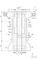
- FIG. 1 is a plan view of a pet diaper according to one embodiment, viewed from the skin side.
- FIG. FIG. 2 is a plan view of the pet diaper of FIG. 1 as viewed from the non-skin side.
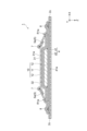
- FIG. 2 is a cross-sectional view of the pet diaper taken along line III-III in FIG. 1 .
- FIG. 4 is a cross-sectional view of the pet diaper taken along line IV-IV in FIG.
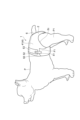
- FIG. 2 is a diagram showing an example of a state in which a pet diaper is worn.
- FIG. 4 is an enlarged view of the first sheet as viewed from the skin side.
- FIG. 2 is an enlarged view of the exterior sheet as viewed from the non-skin side.
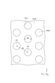
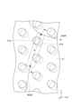
- FIG. 1 is an enlarged view of a portion including a boundary region of the main body portion as viewed from the skin side.
- FIG. 4 is a diagram showing an example of a hot melt adhesive applied to each of the first sheet and the exterior sheet.
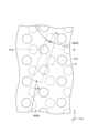
- 13 is an enlarged view of a portion including a boundary region of a main body portion according to a modified example, as viewed from the skin side.
- the back sheet is An outer sheet made of a nonwoven fabric constituting the outermost surface of the main body; an inner sheet disposed between the outer sheet and the absorbent core,
- the main body is provided with a tail insertion portion for inserting the tail of the pet,
- the tail insertion portion has a first cut portion formed by cutting the main body portion in a thickness direction, which is a stacking direction of the sheets constituting the main body portion, and a second cut portion provided separately from the first cut portion,
- a pet diaper wherein at least one of the top sheet and the outer sheet is provided with at least one opening penetrating in the thickness direction and having a predetermined area in the boundary region between the first cut portion and the
- the tail insertion portion has a first cut portion and a second cut portion that are provided separately from each other. That is, the first cut portion and the second cut portion are connected to form a tail insertion hole of a predetermined size.
- an opening is provided in at least one of the top sheet and the outer sheet that constitute the main body portion in the boundary area between the first cut portion and the second cut portion.
- the portion of the main body portion corresponding to the boundary area being easier to tear, when a user tries to tear the portion to connect the first cut portion and the second cut portion when using the pet diaper, it is also possible to prevent the main body portion from tearing in an unexpected direction. Therefore, according to the above pet diaper, the tearing process for connecting multiple cut portions can be performed easily and accurately.
- the first cut portion and the second cut portion are prevented from being connected through the opening, and the first cut portion and the second cut portion can be appropriately maintained in a separated state.
- the first cut portion and the second cut portion can be more appropriately maintained in a separated state before the pet diaper is used, and unintentional tearing of the portion corresponding to the boundary region of the main body portion (the portion between the first cut portion and the second cut portion) can be prevented.
- the shortest distance between the first cut portion and the second cut portion By setting the shortest distance between the first cut portion and the second cut portion to 3 mm or more, it is possible to effectively prevent the portion of the main body portion that corresponds to the boundary region from being unintentionally torn, and by keeping the shortest distance to 5 mm or less, it is possible to prevent the portion of the main body portion that corresponds to the boundary region from being difficult to break.
- the at least one opening includes a plurality of openings arranged in a regular pattern;
- the inner sheet can be easily torn. As a result, the tearing process of the portion corresponding to the boundary region of the main body can be made even easier.
- the material strength (thickness) of the main body can be reduced in the area where the first opening and the second opening overlap, making that area easier to break. As a result, the breaking process of the area corresponding to the boundary region of the main body can be made even easier.
- Fig. 1 is a plan view of the pet diaper 1 as viewed from the skin side.
- Fig. 2 is a plan view of the pet diaper 1 as viewed from the non-skin side.
- Figs. 1 and 2 show the pet diaper 1 in an elongated state in which the pet diaper 1 is elongated to a state in which no wrinkles are formed.
- Fig. 3 is a cross-sectional view of the pet diaper 1 taken along line III-III in Fig. 1.
- Fig. 4 is a cross-sectional view of the pet diaper 1 taken along line IV-IV in Fig. 1.
- Figs. 1 is a plan view of the pet diaper 1 as viewed from the skin side.
- Fig. 2 is a plan view of the pet diaper 1 as viewed from the non-skin side.
- Figs. 1 and 2 show the pet diaper 1 in an elongated state in which the pet diaper 1 is elongated to a state in which no wrinkles are formed.
- the "skin side” is the side that faces the pet's skin when the pet diaper 1 is worn on the pet.
- the “non-skin side” is the side that faces away from the pet's skin when worn.
- the pet diaper 1 has a longitudinal direction Y that connects the pet's ventral side to the pet's dorsal side, a width direction X that is perpendicular to the longitudinal direction Y and is disposed along the pet's waist circumference direction, and a thickness direction Z that is perpendicular to the longitudinal direction Y and the width direction X.
- the thickness direction Z is the layering direction of each material (first sheet 31, second sheet 32, back sheet 4, absorbent body 10, etc. described later) that constitutes the pet diaper 1.
- the straight line that passes through the center of the width direction X of the pet diaper 1 and is parallel to the longitudinal direction Y is represented as the "center line CL".
- the pet diaper 1 has a main body 2 extending in the longitudinal direction Y and the width direction X.
- the main body 2 absorbs urine excreted by a pet wearing the pet diaper 1.
- the main body 2 is divided into a ventral portion 21 located on the ventral side of the pet when the diaper 1 is worn, a dorsal portion 22 located on the dorsal side of the pet when the diaper 1 is worn, and a crotch portion 23 located between the ventral portion 21 and the dorsal portion 22.
- the ventral portion 21, the crotch portion 23, and the dorsal portion 22 are aligned along the longitudinal direction Y from the ventral side (front) to the dorsal side (rear) of the pet.
- the one region located on the most ventral side corresponds to the ventral portion 21
- the one region located on the most dorsal side corresponds to the dorsal portion 22
- the two regions located between the ventral portion 21 and the dorsal portion 22 correspond to the crotch portion 23.
- the main body 2 has a first sheet 31 (top sheet), a second sheet 32, a back sheet 4, a pair of side sheets 5, and an absorbent body 10.
- the first sheet 31 is a sheet made of nonwoven fabric that is placed in a position facing the pet's skin when worn.
- the first sheet 31 is, for example, an air-through nonwoven fabric, a spunbond nonwoven fabric, a meltblown nonwoven fabric, a point-bonded nonwoven fabric, a needle-punched nonwoven fabric, a spunlace nonwoven fabric, or other nonwoven fabric.
- the first sheet 31 is made of air-through nonwoven fabric.
- the fiber material of the first sheet 31 include rayon, acetate, cotton, pulp, synthetic fibers, and the like.
- the first sheet 31 is placed between the tops of the side sheets 5 on both the left and right sides in the stretched state (FIG.
- the first sheet 31 is bonded to the second sheet 32 with a hot melt adhesive (HMA).
- HMA hot melt adhesive
- the second sheet 32 is a liquid-permeable sheet disposed between the first sheet 31 and the absorbent body 10.
- the second sheet 32 may be made of, for example, the same nonwoven fabric as the first sheet 31.
- the second sheet 32 is provided to be wider than the first sheet 31, and is also provided at a position where it overlaps with the pair of side sheets 5.
- the back sheet 4 is a liquid-impermeable sheet that is placed on the side opposite to the pet's skin when the diaper is worn.
- the back sheet 4 can be formed, for example, of a liquid-impermeable nonwoven fabric, a synthetic resin film, or a composite sheet of these.
- the back sheet 4 has an exterior sheet 41 (outer sheet) and a leak-proof sheet 42 (inner sheet).
- the exterior sheet 41 is placed on the outer side (non-skin side) of the leak-proof sheet 42 and constitutes the outermost surface of the main body 2.
- the exterior sheet 41 is formed, for example, of a liquid-impermeable nonwoven fabric.
- the leak-proof sheet 42 is placed between the exterior sheet 41 and the absorbent 10 (absorbent core 11) and is joined to the exterior sheet 41. More specifically, the exterior sheet 41 is joined to the leak-proof sheet 42 by a hot melt adhesive (HMA).
- HMA hot melt adhesive
- the leak-proof sheet 42 is formed, for example, of a liquid-impermeable synthetic resin film.
- a pair of side sheets 5 are sheets for forming leg side gathers LSG, which are standing up leak-proof gathers, in the abdominal portion 21 and the crotch portion 23.
- the side sheets 5 may be formed, for example, from a nonwoven fabric having water repellency or hydrophobicity. As shown in Figures 1, 3, and 4, each side sheet 5 is arranged on both sides of the main body portion 2 in the width direction X so as to expose the first sheet 31. Each side sheet 5 extends along the longitudinal direction Y from the abdominal end 2a of the main body portion 2 to the dorsal end 2b of the main body portion 2.
- each side sheet 5 in the width direction X coincides with the outer edge of the back sheet 4, forming the outer edge portion 2c of the main body portion 2.
- the inner portion of each side sheet 5 in the width direction X is folded back to the non-skin side.
- an elastic member 7 stretched in the longitudinal direction Y is arranged from the abdominal portion 21 to the crotch portion 23.
- the elastic member 7 is, for example, rubber thread.
- each side sheet 5 is joined (fixed) to the second sheet 32 at a fixing portion R surrounded by a dashed line and hatched with diagonal lines.
- Each fixing portion R is disposed over the entire area in the longitudinal direction Y of the main body portion 2.
- Each fixing portion R has a fixing portion R1 extending in the longitudinal direction Y along the outer edge of the fixing portion R in the width direction X, a rectangular fixing portion R2 formed at the ventral end of the fixing portion R in the longitudinal direction Y, and a rectangular fixing portion R3 formed at the dorsal end of the fixing portion R in the longitudinal direction Y.
- the standing portion 5a is formed by the portion of the side sheet 5 between the inner end R2a in the longitudinal direction Y of the fixed portion R2 and the inner end R3a in the longitudinal direction Y of the fixed portion R3 (i.e., the portion of the side sheet 5 where the elastic member 7 is disposed and which is not joined to the second sheet 32).
- the standing portion 5a is a portion which functions as a leg side gather LSG by standing up due to the contraction of the elastic member 7. More specifically, the standing portion 5a is configured such that both ends in the longitudinal direction Y are fixed by the fixed portions R2 and R3 and it contracts in the longitudinal direction Y, thereby standing up with the inner end R1a in the width direction X of the fixed portion R1 as a fulcrum. In other words, the end R1a of the fixed portion R1 functions as a fulcrum for standing the leg side gather LSG.
- the absorbent body 10 is disposed between the first sheet 31 and the back sheet 4 (between the second sheet 32 and the leakproof sheet 42 in this embodiment). As shown in FIG. 3, the absorbent body 10 is composed of an absorbent core 11 and a core wrap 12 covering the upper and lower surfaces of the absorbent core 11.
- the absorbent core 11 is disposed so as to cover the abdominal portion 21 and the crotch portion 23, and is not disposed in the dorsal portion 22.
- the absorbent core 11 is a member that absorbs pet urine and has liquid absorption and liquid retention properties.
- the absorbent core 11 is, for example, a laminate of absorbent materials including ground pulp or superabsorbent polymer (SAP), or a mixture thereof.
- the core wrap 12 is, for example, a tissue or a nonwoven fabric sheet.
- the absorbent core 11 is formed in a gourd shape (or an hourglass shape) when viewed from the thickness direction Z, and the center of the absorbent core 11 in the longitudinal direction Y has a narrowed shape.
- the main body 2 is provided with a tail insertion section 6 for inserting a pet's tail.
- the tail insertion section 6 is composed of one cut section 6a (first cut section) and two cut sections 6b (second cut sections) provided separately from the cut section 6a.
- the cut sections 6a, 6b are formed by cutting the main body 2 in the thickness direction Z, and penetrate the main body 2 in the thickness direction Z.
- the cut section 6a is provided in the center of the width direction X of the region of the crotch section 23 on the rear side of the absorbent core 11.
- the cut section 6a is formed in a curved shape (arc shape) that extends in the width direction X across the center line CL and is convex on the rear side.
- the two cut sections 6b are provided on both sides of the center line CL at a position closer to the cut section 6a and on the rear side of the cut section 6a.
- the two cut portions 6b are linearly shaped and inclined with respect to the longitudinal direction Y so that the distance between the two cut portions 6b increases from the ventral side to the dorsal side.
- the tail insertion portion 6 is configured to be able to adjust (enlarge) the opening size by connecting the two cut portions 6b to the cut portion 6a as necessary.
- the shape and size of the tail insertion portion 6 are not limited to those of this embodiment.
- at least one of the cut portions 6a, 6b may be formed by an opening having a predetermined area (for example, an elliptical opening, etc.) instead of a cut.
- a pair of flap portions F1 protruding outward in the width direction X are formed on both sides of the ventral portion 21 in the width direction X.
- a pair of flap portions F2 protruding outward in the width direction X are formed on both sides of the dorsal portion 22 in the width direction X.
- a pair of fastening tabs 50 are provided on the pair of flap portions F1.
- a target portion 53 is provided in the area between the pair of flap portions F2 in the dorsal portion 22.
- Each fastening tab 50 extends from both ends (ends F1a in the width direction X of the flap portion F1) of the main body portion 2 (flap portion F1) in the width direction X outward in the width direction X.
- Each fastening tab 50 has a rectangular shape that is long in the width direction X and is disposed near the end 2a on the ventral side of the main body portion 2.
- Each fastening tab 50 has a base sheet 51 joined to the flap portion F1 and an engagement portion 52 provided on the skin-facing surface of the base sheet 51. A portion of the base sheet 51 is sandwiched, for example, between the side sheet 5 and the back sheet 4.
- the engagement portion 52 is, for example, a hook-and-loop fastener (for example, a plurality of hook-shaped members) configured to be able to engage with the target portion 53.
- the target portion 53 has a rectangular shape that is long in the width direction X, and is disposed near the rear end 2b of the main body portion 2 on the non-skin side surface of the back sheet 4 (exterior sheet 41). As shown in Figure 5, in the attached state, the engagement portions 52 of the pair of fastening tabs 50 engage with the target portion 53. Figure 5 shows the state in which the pet P is standing in the attached state.
- the main body 2 has a pair of elastic members 8 that are arranged extending in the longitudinal direction Y along the outer edge 2c of the main body 2 in the width direction X (in this embodiment, the portion of the outer edge 2c located in the crotch portion 23 where the flap portions F1, F2 are not provided) and that contract in the longitudinal direction Y.
- Each elastic member 8 is, for example, rubber thread similar to the elastic member 7.
- each elastic member 8 is arranged between the second sheet 32 and the back sheet 4 (leak-proof sheet 42).
- the pair of elastic members 8 contract in the longitudinal direction Y, causing the outer edge 2c of the main body 2 to function as leg gathers that fit around the legs of the pet P.
- the pet diaper 1 has a structure that makes it easier to tear the portion between the cut portion 6a and the two cut portions 6b (boundary region B shown in FIG. 8). An example of the structure is described in detail below.
- the first sheet 31 has a plurality of regularly arranged openings 31a (first openings).
- Each opening 31a penetrates in the thickness direction Z and has a predetermined area. That is, unlike a cut, each opening 31a is formed by cutting out a part of the first sheet 31 so as to have a predetermined area.
- each opening 31a is formed in a circular shape when viewed from the thickness direction Z.
- the multiple openings 31a are arranged in a rhombic lattice pattern, and the distance d1 between the centers C1 of two adjacent openings 31a is the same for all openings 31a.
- the width w1 of the openings 31a is, for example, about 1.2 mm.
- the width w1 of the openings 31a is equal to the diameter of the openings 31a. If the opening 31a has a shape other than a circle (e.g., an ellipse), the width w1 of the opening 31a can be defined as the radius of a circle having the smallest radius that contains the opening 31a (in other words, the maximum distance between any two points on the edge of the opening 31a). Since the first sheet 31 is provided on the second sheet 32, the surface of the second sheet 32 is exposed to the skin through the opening 31a.
- the exterior sheet 41 has a plurality of regularly arranged openings 41a (second openings).
- Each opening 41a penetrates in the thickness direction Z and has a predetermined area.
- each opening 41a has a shape similar to that of the opening 31a and is arranged in the same manner as the plurality of openings 31a. That is, each opening 41a is formed in a circular shape when viewed from the thickness direction Z.
- the plurality of openings 41a are arranged in a rhombic lattice pattern, and the distance d2 between the centers C2 of two adjacent openings 41a is the same for all openings 41a.
- the width w2 of the openings 41a is, for example, about 1.2 mm.
- the width w2 of the openings 41a is equal to the diameter of the openings 41a. If the opening 41a has a shape other than a circle (e.g., an ellipse), the width w2 of the opening 41a can be defined as the radius of a circle with the smallest radius that contains the opening 41a (in other words, the maximum distance between any two points on the edge of the opening 41a). Because the exterior sheet 41 is provided on the leakproof sheet 42, the surface of the leakproof sheet 42 is exposed to the non-skin side through the opening 41a.
- At least one of the first sheet 31 and the exterior sheet 41 has at least one opening (opening 31a or opening 41a).
- opening 31a or opening 41a As shown in FIG. 8, in this embodiment, as an example, two openings 31a (i.e., openings 31a arranged so that at least a portion of the opening overlaps with the boundary region B) and two openings 41a (i.e., openings 41a arranged so that at least a portion of the opening overlaps with the boundary region B) are arranged in the boundary region B.
- the boundary region B may be defined as a region along a line segment connecting two points (i.e., point Pa on cut portion 6a and point Pb on cut portion 6b) where the linear distance between cut portion 6a and cut portion 6b is the smallest.
- the boundary region B may be defined as a region (i.e., a region including the above line segment) where the break length required to break main body portion 2 and connect cut portion 6a and cut portion 6b is the shortest.
- point Pb corresponds to the end of cut portion 6b on the cut portion 6a side (ventral side) that extends in a straight line.
- Point Pa corresponds to the position where the distance from point Pb is the smallest.
- the boundary region B may be defined as a rectangular region having a predetermined width (e.g., the same width as the widths w1 and w2 of openings 31a and 41a) in a direction perpendicular to the above line segment and extending from point Pa to point Pb with the above line segment as the center line.
- the boundary region B exists in two places: between the cut portion 6a and the left cut portion 6b, and between the cut portion 6a and the right cut portion 6b.
- FIG. 8 shows a region including the boundary region B between the cut portion 6a and the left cut portion 6b.
- the tail insertion portion 6 has cut portions 6a and 6b that are provided separately from each other. That is, by connecting the cut portions 6a and 6b, a tail insertion hole of a predetermined size (in this embodiment, the size corresponding to the area A in FIG. 2) can be formed.
- a tail insertion hole of a predetermined size in this embodiment, the size corresponding to the area A in FIG. 2
- openings 31a and 41a are provided in at least one of the top sheet (first sheet 31) and the exterior sheet 41 that constitute the main body 2 (both sheets in this embodiment). That is, as shown in FIG.
- At least one opening (two openings 31a and two openings 41a in this embodiment) is arranged so that at least a part of it is included in the boundary area B.
- the material strength of the part of the main body 2 that corresponds to the boundary area B can be weakened, making the part easier to tear.
- the portion of the main body 2 corresponding to the boundary region B becomes easier to tear, the main body 2 is prevented from tearing in an unexpected direction when a user tries to tear that portion to connect the cut portions 6a and 6b while using the pet diaper 1. Therefore, according to the pet diaper 1, the tearing process for connecting the multiple cut portions 6a and 6b can be performed easily and accurately.
- multiple (four in total) openings 31a or 41a are arranged in boundary region B, but in order to obtain the above effect, it is sufficient that at least one opening is arranged in boundary region B. However, from the viewpoint of improving the above effect, it is preferable that multiple openings are arranged in boundary region B, as in this embodiment.
- the width w1 of the opening 31a is smaller than the shortest distance between the cut portions 6a and 6b (i.e., the distance d between points Pa and Pb).
- the width w2 of the opening 41a is also smaller than the distance d. In other words, "w1 ⁇ d” and "w2 ⁇ d” are satisfied.
- the widths w1, w2 of the openings 31a, 41a are set to 1/2 or less of the shortest distance (distance d). In other words, "w1 ⁇ d/2" and "w2 ⁇ d/2" are established.
- the distance d is preferably set to 3 mm or more and 5 mm or less.
- the distance d is preferably set to 3 mm or more and 5 mm or less.
- the first sheet 31 is joined to the second sheet 32 by the hot melt adhesive.
- a linear hot melt adhesive H discharged in a spiral shape from a plurality of nozzles (not shown) arranged in the width direction X is disposed between the first sheet 31 and the second sheet 32, thereby joining the first sheet 31 to the second sheet 32.
- the width dH (line width) of such hot melt adhesive H is larger than the width w1 of the opening 31a and smaller than the distance d1 (opening pitch) between the centers C1 of two adjacent openings 31a.
- the width dH is set to the width w1 of the opening 31a or less, for example, when the hot melt adhesive H is applied to the first sheet 31, the entire line width of the hot melt adhesive H may enter the opening 31a, and the hot melt adhesive H may easily leak out from the opening 31a.
- the width dH is set to be greater than the width w1, it is possible to prevent the hot melt adhesive H from leaking out through the opening 31a as described above, and to ensure the adhesive strength between the first sheet 31 and the second sheet 32.
- the width dH is set to the distance d1 or more, the entire opening 31a is likely to be covered with the hot melt adhesive H, and the effect of the opening 31a (for example, the effect of facilitating the breaking of the boundary region B as described above, the effect of increasing breathability, etc.) may be impaired. From the above viewpoints, it is preferable that the width dH is set to "w1 ⁇ dH ⁇ d1".
- a linear hot melt adhesive H discharged in a spiral shape is disposed between the exterior sheet 41 and the leakproof sheet 42, thereby bonding the exterior sheet 41 to the leakproof sheet 42.
- the width dH (line width) of the hot melt adhesive H is larger than the width w2 of the opening 41a and smaller than the distance d2 (opening pitch) between the centers C2 of two adjacent openings 41a (i.e., set to "w2 ⁇ dH ⁇ d2").
- the moisture permeability of the leak-proof sheet 42 is preferably 500 g/( m2 ⁇ 24 h) or more. That is, the material of the leak-proof sheet 42 preferably satisfies the above moisture permeability conditions.
- the moisture permeability of the leak-proof sheet 42 can be measured by the moisture permeability test method (cup method) for moisture-proof packaging materials specified in "JIS Z 0208:1976". Alternatively, it is preferable that a plurality of micropores are formed in the leak-proof sheet 42.
- the width (diameter) of the micropores is, for example, 0.05 mm or more and 1.0 mm or less
- the center-to-center distance (pitch) of adjacent micropores is, for example, 0.05 mm or more and 1.0 mm or less.
- the leak-proof sheet 42 may satisfy both of the above requirements. That is, the leak-proof sheet 42 may have a plurality of micropores formed therein and may also satisfy the above moisture permeability conditions. By configuring the leak-proof sheet 42 so as to satisfy at least one of the above requirements, it is possible to make the leak-proof sheet 42 (the portion disposed in the boundary region B of the main body 2) easier to break. As a result, the breaking process of the portion of the main body 2 corresponding to the boundary region B can be made even easier.
- the first sheet 31 has at least one opening 31a
- the exterior sheet 41 has at least one opening 41a.
- two openings 31a and two openings 41a are arranged so as to at least partially overlap in the boundary region B.
- At least one opening 31a and at least one opening 41a have overlapping portions in the Z-axis direction.
- each of the two openings 31a and each of the two openings 41a have overlapping portions in boundary region B.
- the openings 31a and the openings 41a may not overlap with each other in the Z-axis direction.
- the openings 31a and the openings 41a may be arranged so as not to overlap with each other in the Z-axis direction.
- the positions of the multiple openings 31a and the multiple openings 41a arranged in a similar rhombic lattice are shifted, so that the openings 31a and the openings 41a are arranged so as not to overlap with each other in regions other than the boundary region B.
- the tail insertion portion 6 is positioned in a position that does not overlap with the absorbent core 11. That is, in the area where the tail insertion portion 6 is provided (for example, area A in FIG. 2), no liquid-absorbing layer (absorbent body 10) is provided between the second sheet 32 and the leak-proof sheet 42, and the second sheet 32 and the leak-proof sheet 42 are joined to each other with an adhesive such as a hot melt adhesive. This prevents urine from leaking from the edge (notch) of the tail insertion portion 6. Furthermore, by providing multiple openings 31a in the first sheet 31 on the absorbent body 10, urine can be appropriately prevented from flowing or being retained on the surface of the first sheet 31.
- the sheet placed on the absorbent body 10 has a two-layer structure of a first sheet 31 and a second sheet 32, and openings 31a are provided only in the upper first sheet 31, while the second sheet 32 that covers the absorbent body 10 does not have any openings, thereby making it possible to appropriately prevent SAP and other substances contained in the absorbent body 10 (mainly the absorbent core 11) from leaking to the outside.
- the openings 31a, 41a are formed in both the first sheet 31 and the exterior sheet 41, but openings may be formed in only one of the first sheet 31 and the exterior sheet 41. Furthermore, from the viewpoint of facilitating the breaking process of the portion corresponding to the boundary region B described above, the openings 31a or the openings 41a may be provided only in the boundary region B. In other words, the openings 31a or the openings 41a may not be provided in areas other than the boundary region B. Furthermore, the arrangement pattern of the multiple openings 31a is not limited to the diamond lattice pattern of the above embodiment, and may be arranged according to other arrangement patterns. Furthermore, the multiple openings 31a may be arranged irregularly. The same applies to the multiple openings 41a.
- the sheet member closer to the skin than the absorbent body 10 is composed of two layers of sheets (first sheet 31 and second sheet 32), but it may be composed of only a single top sheet. In this case, an opening similar to opening 31a may be provided in the top sheet layer.
Landscapes
- Life Sciences & Earth Sciences (AREA)
- Environmental Sciences (AREA)
- Animal Husbandry (AREA)
- Biodiversity & Conservation Biology (AREA)
- Absorbent Articles And Supports Therefor (AREA)
- Health & Medical Sciences (AREA)
- General Health & Medical Sciences (AREA)
- Engineering & Computer Science (AREA)
- Biomedical Technology (AREA)
- Heart & Thoracic Surgery (AREA)
- Vascular Medicine (AREA)
- Animal Behavior & Ethology (AREA)
- Epidemiology (AREA)
- Public Health (AREA)
- Veterinary Medicine (AREA)
- Zoology (AREA)
- Housing For Livestock And Birds (AREA)
Abstract
Description
ペットに装着されるペット用おむつであって、
前記ペット用おむつが前記ペットに装着された装着状態において前記ペットの肌に面する位置に配置される不織布からなる表面シートと、
前記装着状態において前記ペットの肌側とは反対側に配置される裏面シートと、
前記表面シートと前記裏面シートとの間に配置される吸収性コアと、を有する本体部を備え、
前記裏面シートは、
前記本体部の最外面を構成する不織布からなる外側シートと、
前記外側シートと前記吸収性コアとの間に配置された内側シートと、を有し、
前記本体部には、前記ペットの尻尾を挿通させるための尻尾挿通部が設けられており、
前記尻尾挿通部は、前記本体部を構成するシートの積層方向である厚さ方向に前記本体部を切断することにより形成された第1切断部及び前記第1切断部から分離して設けられた第2切断部を有し、
前記本体部の前記第1切断部と前記第2切断部との間の境界領域において、前記表面シート及び前記外側シートの少なくとも一方には、前記厚さ方向に貫通し所定の面積を有する少なくとも一つの開口部が設けられている、ペット用おむつ。
前記開口部の幅は、前記第1切断部と前記第2切断部との最短距離よりも小さい、態様1のペット用おむつ。
前記開口部の幅は、前記最短距離の1/2以下である、態様2のペット用おむつ。
前記最短距離は、3mm以上5mm以下である、態様3のペット用おむつ。
前記少なくとも一つの開口部は、規則的に配列された複数の開口部を含み、
前記複数の開口部が設けられた前記表面シート及び前記外側シートの少なくとも一方のうち前記尻尾挿通部を含む領域に接着された線状のホットメルト接着剤の幅は、前記開口部の幅よりも大きく、且つ、互いに隣接する2つの前記開口部の中心間の距離よりも小さい、態様1~4のいずれかのペット用おむつ。
前記内側シートの透湿度は、500g/(m2・24h)以上である、態様1~5のいずれかのペット用おむつ。
前記内側シートには、複数の微細孔が形成されている、態様1~6のいずれかのペット用おむつ。
前記境界領域において、前記表面シートには、前記厚さ方向に貫通し所定の面積を有する少なくとも一つの第1開口部が設けられており、前記外側シートには、前記厚さ方向に貫通し所定の面積を有する少なくとも一つの第2開口部が設けられている、態様1~7のいずれかのペット用おむつ。
前記境界領域において、前記少なくとも一つの第1開口部と前記少なくとも一つの第2開口部とは、前記厚さ方向において互いに重なる部分を有する、態様8のペット用おむつ。
前記境界領域において、前記第1開口部と前記第2開口部とが前記厚さ方向において互いに重なる部分は設けられていない、態様8のペット用おむつ。
以下、本開示の実施形態について、図面を参照しつつ詳細に説明する。なお、以下の説明において、同一又は相当要素には同一符号を用い、重複する説明を省略する。
以上、本開示の実施形態について説明したが、本開示は、上記実施形態に限られない。各構成の材料及び形状には、上述した材料及び形状に限らず、様々な材料及び形状を採用することができる。また、上述した実施形態の構成に含まれる一部の構成は、変更又は省略されてもよいし、他の構成が付加されてもよい。
Claims (10)
- ペットに装着されるペット用おむつであって、
前記ペット用おむつが前記ペットに装着された装着状態において前記ペットの肌に面する位置に配置される不織布からなる表面シートと、
前記装着状態において前記ペットの肌側とは反対側に配置される裏面シートと、
前記表面シートと前記裏面シートとの間に配置される吸収性コアと、を有する本体部を備え、
前記裏面シートは、
前記本体部の最外面を構成する不織布からなる外側シートと、
前記外側シートと前記吸収性コアとの間に配置された内側シートと、を有し、
前記本体部には、前記ペットの尻尾を挿通させるための尻尾挿通部が設けられており、
前記尻尾挿通部は、前記本体部を構成するシートの積層方向である厚さ方向に前記本体部を切断することにより形成された第1切断部及び前記第1切断部から分離して設けられた第2切断部を有し、
前記本体部の前記第1切断部と前記第2切断部との間の境界領域において、前記表面シート及び前記外側シートの少なくとも一方には、前記厚さ方向に貫通し所定の面積を有する少なくとも一つの開口部が設けられている、ペット用おむつ。 - 前記開口部の幅は、前記第1切断部と前記第2切断部との最短距離よりも小さい、
請求項1に記載のペット用おむつ。 - 前記開口部の幅は、前記最短距離の1/2以下である、
請求項2に記載のペット用おむつ。 - 前記最短距離は、3mm以上5mm以下である、
請求項3に記載のペット用おむつ。 - 前記少なくとも一つの開口部は、規則的に配列された複数の開口部を含み、
前記複数の開口部が設けられた前記表面シート及び前記外側シートの少なくとも一方のうち前記尻尾挿通部を含む領域に接着された線状のホットメルト接着剤の幅は、前記開口部の幅よりも大きく、且つ、互いに隣接する2つの前記開口部の中心間の距離よりも小さい、
請求項1に記載のペット用おむつ。 - 前記内側シートの透湿度は、500g/(m2・24h)以上である、
請求項1に記載のペット用おむつ。 - 前記内側シートには、複数の微細孔が形成されている、
請求項1に記載のペット用おむつ。 - 前記境界領域において、前記表面シートには、前記厚さ方向に貫通し所定の面積を有する少なくとも一つの第1開口部が設けられており、前記外側シートには、前記厚さ方向に貫通し所定の面積を有する少なくとも一つの第2開口部が設けられている、
請求項1に記載のペット用おむつ。 - 前記境界領域において、前記少なくとも一つの第1開口部と前記少なくとも一つの第2開口部とは、前記厚さ方向において互いに重なる部分を有する、
請求項8に記載のペット用おむつ。 - 前記境界領域において、前記第1開口部と前記第2開口部とが前記厚さ方向において互いに重なる部分は設けられていない、
請求項8に記載のペット用おむつ。
Priority Applications (4)
| Application Number | Priority Date | Filing Date | Title |
|---|---|---|---|
| EP24888656.6A EP4755179A1 (en) | 2023-11-07 | 2024-11-01 | Pet diaper |
| KR1020267013439A KR20260108986A (ko) | 2023-11-07 | 2024-11-01 | 반려동물용 기저귀 |
| AU2024376692A AU2024376692A1 (en) | 2023-11-07 | 2024-11-01 | Pet diaper |
| CN202480069411.8A CN122121738A (zh) | 2023-11-07 | 2024-11-01 | 宠物用尿布 |
Applications Claiming Priority (2)
| Application Number | Priority Date | Filing Date | Title |
|---|---|---|---|
| JP2023189842A JP2025077561A (ja) | 2023-11-07 | 2023-11-07 | ペット用おむつ |
| JP2023-189842 | 2023-11-07 |
Publications (1)
| Publication Number | Publication Date |
|---|---|
| WO2025100360A1 true WO2025100360A1 (ja) | 2025-05-15 |
Family
ID=95695693
Family Applications (1)
| Application Number | Title | Priority Date | Filing Date |
|---|---|---|---|
| PCT/JP2024/039081 Pending WO2025100360A1 (ja) | 2023-11-07 | 2024-11-01 | ペット用おむつ |
Country Status (7)
| Country | Link |
|---|---|
| EP (1) | EP4755179A1 (ja) |
| JP (1) | JP2025077561A (ja) |
| KR (1) | KR20260108986A (ja) |
| CN (1) | CN122121738A (ja) |
| AU (1) | AU2024376692A1 (ja) |
| TW (1) | TW202533767A (ja) |
| WO (1) | WO2025100360A1 (ja) |
Citations (5)
| Publication number | Priority date | Publication date | Assignee | Title |
|---|---|---|---|---|
| JPH1075679A (ja) * | 1996-07-11 | 1998-03-24 | Ota Eizai Kk | ペット用紙おむつ |
| JP2012205561A (ja) * | 2011-03-30 | 2012-10-25 | Daio Paper Corp | ペット用パンツタイプ使い捨ておむつの製造方法、及びペット用パンツタイプ使い捨ておむつ |
| JP2012205542A (ja) | 2011-03-29 | 2012-10-25 | Unicharm Corp | ペット用おむつ |
| JP2021136957A (ja) * | 2020-03-06 | 2021-09-16 | ユニ・チャーム株式会社 | ペット用おむつ |
| JP2023141818A (ja) * | 2022-03-24 | 2023-10-05 | ユニ・チャーム株式会社 | ペット用おむつ |
-
2023
- 2023-11-07 JP JP2023189842A patent/JP2025077561A/ja active Pending
-
2024
- 2024-11-01 KR KR1020267013439A patent/KR20260108986A/ko active Pending
- 2024-11-01 WO PCT/JP2024/039081 patent/WO2025100360A1/ja active Pending
- 2024-11-01 AU AU2024376692A patent/AU2024376692A1/en active Pending
- 2024-11-01 EP EP24888656.6A patent/EP4755179A1/en active Pending
- 2024-11-01 CN CN202480069411.8A patent/CN122121738A/zh active Pending
- 2024-11-06 TW TW113142444A patent/TW202533767A/zh unknown
Patent Citations (5)
| Publication number | Priority date | Publication date | Assignee | Title |
|---|---|---|---|---|
| JPH1075679A (ja) * | 1996-07-11 | 1998-03-24 | Ota Eizai Kk | ペット用紙おむつ |
| JP2012205542A (ja) | 2011-03-29 | 2012-10-25 | Unicharm Corp | ペット用おむつ |
| JP2012205561A (ja) * | 2011-03-30 | 2012-10-25 | Daio Paper Corp | ペット用パンツタイプ使い捨ておむつの製造方法、及びペット用パンツタイプ使い捨ておむつ |
| JP2021136957A (ja) * | 2020-03-06 | 2021-09-16 | ユニ・チャーム株式会社 | ペット用おむつ |
| JP2023141818A (ja) * | 2022-03-24 | 2023-10-05 | ユニ・チャーム株式会社 | ペット用おむつ |
Also Published As
| Publication number | Publication date |
|---|---|
| AU2024376692A1 (en) | 2026-05-14 |
| KR20260108986A (ko) | 2026-07-09 |
| EP4755179A1 (en) | 2026-06-10 |
| CN122121738A (zh) | 2026-05-29 |
| JP2025077561A (ja) | 2025-05-19 |
| TW202533767A (zh) | 2025-09-01 |
Similar Documents
| Publication | Publication Date | Title |
|---|---|---|
| JP5089269B2 (ja) | 吸収パッド、及び吸収性物品 | |
| JP3130365B2 (ja) | 肌当て上面シートに弾性開口部を有する使い捨てオムツ及びその弾性開口部を形成する方法 | |
| JP5566594B2 (ja) | 吸収性物品 | |
| KR100821816B1 (ko) | 일회용 기저귀 | |
| US10786399B2 (en) | Disposable pant-type absorbent article | |
| JP3805622B2 (ja) | 使い捨ておむつ | |
| JP2002172135A (ja) | 使い捨て着用物品 | |
| JP2011136095A (ja) | 使い捨て着用物品 | |
| KR101582713B1 (ko) | 일회용 기저귀 | |
| JP2003088547A (ja) | 使い捨ておむつ | |
| JP5767783B2 (ja) | パンツタイプ使い捨ておむつ | |
| JP5340696B2 (ja) | 吸収性物品 | |
| JP4823956B2 (ja) | 吸収性物品の製造方法および吸収性物品 | |
| JP2010142489A (ja) | 使い捨て吸収性物品 | |
| JP2004350809A (ja) | パンツ型使い捨ておむつ | |
| CN100427048C (zh) | 一次性尿布 | |
| WO2018123637A1 (ja) | 吸収性物品 | |
| JP2025077561A (ja) | ペット用おむつ | |
| JP3398096B2 (ja) | 使い捨てパンツ | |
| JP4315848B2 (ja) | 吸収性物品 | |
| CN119343114A (zh) | 短裤型吸收性物品 | |
| JP5192905B2 (ja) | 吸収性物品及び吸収性本体保持カバー | |
| JP5401234B2 (ja) | パンツタイプ使い捨ておむつ | |
| JP7719144B2 (ja) | ペット用おむつ | |
| JP3248846U (ja) | 吸収性物品 |
Legal Events
| Date | Code | Title | Description |
|---|---|---|---|
| 121 | Ep: the epo has been informed by wipo that ep was designated in this application |
Ref document number: 24888656 Country of ref document: EP Kind code of ref document: A1 |
|
| WWE | Wipo information: entry into national phase |
Ref document number: 2024888656 Country of ref document: EP |
|
| WWE | Wipo information: entry into national phase |
Ref document number: 202647050023 Country of ref document: IN |
|
| WWE | Wipo information: entry into national phase |
Ref document number: 2601002847 Country of ref document: TH |
|
| WWE | Wipo information: entry into national phase |
Ref document number: AU2024376692 Country of ref document: AU |
|
| ENP | Entry into the national phase |
Ref document number: 2024376692 Country of ref document: AU Date of ref document: 20241101 Kind code of ref document: A |
|
| NENP | Non-entry into the national phase |
Ref country code: DE |