WO2025100240A1 - 遊星歯車機構のサンギヤユニット、変速機 - Google Patents
遊星歯車機構のサンギヤユニット、変速機 Download PDFInfo
- Publication number
- WO2025100240A1 WO2025100240A1 PCT/JP2024/037808 JP2024037808W WO2025100240A1 WO 2025100240 A1 WO2025100240 A1 WO 2025100240A1 JP 2024037808 W JP2024037808 W JP 2024037808W WO 2025100240 A1 WO2025100240 A1 WO 2025100240A1
- Authority
- WO
- WIPO (PCT)
- Prior art keywords
- sun gear
- shaft
- gear shaft
- raceway surface
- gear unit
- Prior art date
- Legal status (The legal status is an assumption and is not a legal conclusion. Google has not performed a legal analysis and makes no representation as to the accuracy of the status listed.)
- Pending
Links
Images





Classifications
-
- F—MECHANICAL ENGINEERING; LIGHTING; HEATING; WEAPONS; BLASTING
- F16—ENGINEERING ELEMENTS AND UNITS; GENERAL MEASURES FOR PRODUCING AND MAINTAINING EFFECTIVE FUNCTIONING OF MACHINES OR INSTALLATIONS; THERMAL INSULATION IN GENERAL
- F16C—SHAFTS; FLEXIBLE SHAFTS; ELEMENTS OR CRANKSHAFT MECHANISMS; ROTARY BODIES OTHER THAN GEARING ELEMENTS; BEARINGS
- F16C19/00—Bearings with rolling contact, for exclusively rotary movement
- F16C19/02—Bearings with rolling contact, for exclusively rotary movement with bearing balls essentially of the same size in one or more circular rows
- F16C19/10—Bearings with rolling contact, for exclusively rotary movement with bearing balls essentially of the same size in one or more circular rows for axial load mainly
-
- F—MECHANICAL ENGINEERING; LIGHTING; HEATING; WEAPONS; BLASTING
- F16—ENGINEERING ELEMENTS AND UNITS; GENERAL MEASURES FOR PRODUCING AND MAINTAINING EFFECTIVE FUNCTIONING OF MACHINES OR INSTALLATIONS; THERMAL INSULATION IN GENERAL
- F16C—SHAFTS; FLEXIBLE SHAFTS; ELEMENTS OR CRANKSHAFT MECHANISMS; ROTARY BODIES OTHER THAN GEARING ELEMENTS; BEARINGS
- F16C19/00—Bearings with rolling contact, for exclusively rotary movement
- F16C19/02—Bearings with rolling contact, for exclusively rotary movement with bearing balls essentially of the same size in one or more circular rows
- F16C19/14—Bearings with rolling contact, for exclusively rotary movement with bearing balls essentially of the same size in one or more circular rows for both radial and axial load
- F16C19/16—Bearings with rolling contact, for exclusively rotary movement with bearing balls essentially of the same size in one or more circular rows for both radial and axial load with a single row of balls
-
- F—MECHANICAL ENGINEERING; LIGHTING; HEATING; WEAPONS; BLASTING
- F16—ENGINEERING ELEMENTS AND UNITS; GENERAL MEASURES FOR PRODUCING AND MAINTAINING EFFECTIVE FUNCTIONING OF MACHINES OR INSTALLATIONS; THERMAL INSULATION IN GENERAL
- F16C—SHAFTS; FLEXIBLE SHAFTS; ELEMENTS OR CRANKSHAFT MECHANISMS; ROTARY BODIES OTHER THAN GEARING ELEMENTS; BEARINGS
- F16C33/00—Parts of bearings; Special methods for making bearings or parts thereof
- F16C33/30—Parts of ball or roller bearings
- F16C33/58—Raceways; Race rings
-
- F—MECHANICAL ENGINEERING; LIGHTING; HEATING; WEAPONS; BLASTING
- F16—ENGINEERING ELEMENTS AND UNITS; GENERAL MEASURES FOR PRODUCING AND MAINTAINING EFFECTIVE FUNCTIONING OF MACHINES OR INSTALLATIONS; THERMAL INSULATION IN GENERAL
- F16C—SHAFTS; FLEXIBLE SHAFTS; ELEMENTS OR CRANKSHAFT MECHANISMS; ROTARY BODIES OTHER THAN GEARING ELEMENTS; BEARINGS
- F16C35/00—Rigid support of bearing units; Housings, e.g. caps, covers
- F16C35/04—Rigid support of bearing units; Housings, e.g. caps, covers in the case of ball or roller bearings
- F16C35/06—Mounting or dismounting of ball or roller bearings; Fixing them onto shaft or in housing
- F16C35/07—Fixing them on the shaft or housing with interposition of an element
- F16C35/077—Fixing them on the shaft or housing with interposition of an element between housing and outer race ring
-
- F—MECHANICAL ENGINEERING; LIGHTING; HEATING; WEAPONS; BLASTING
- F16—ENGINEERING ELEMENTS AND UNITS; GENERAL MEASURES FOR PRODUCING AND MAINTAINING EFFECTIVE FUNCTIONING OF MACHINES OR INSTALLATIONS; THERMAL INSULATION IN GENERAL
- F16C—SHAFTS; FLEXIBLE SHAFTS; ELEMENTS OR CRANKSHAFT MECHANISMS; ROTARY BODIES OTHER THAN GEARING ELEMENTS; BEARINGS
- F16C43/00—Assembling bearings
- F16C43/04—Assembling rolling-contact bearings
- F16C43/06—Placing rolling bodies in cages or bearings
-
- F—MECHANICAL ENGINEERING; LIGHTING; HEATING; WEAPONS; BLASTING
- F16—ENGINEERING ELEMENTS AND UNITS; GENERAL MEASURES FOR PRODUCING AND MAINTAINING EFFECTIVE FUNCTIONING OF MACHINES OR INSTALLATIONS; THERMAL INSULATION IN GENERAL
- F16H—GEARING
- F16H1/00—Toothed gearings for conveying rotary motion
- F16H1/28—Toothed gearings for conveying rotary motion with gears having orbital motion
Definitions
- This disclosure relates to a sun gear unit of a planetary gear mechanism and a transmission.
- Patent Document 1 there is a transmission (reduction gear) that reduces the rotational speed of the drive shaft of the drive unit and outputs it.
- This transmission has multiple rotating shafts with gears attached, and reduces the rotational speed by sequentially transmitting the rotation of the drive shaft to the multiple rotating shafts.
- the sun gear shaft of the sun gear unit of the planetary gear mechanism is rotatably supported by a support part via a bearing. If this sun gear shaft wobble, it is possible that rotational performance and durability may decrease.
- the present disclosure therefore aims to provide a sun gear unit of a planetary gear mechanism that can stably and rotatably support the sun gear shaft, and a transmission.
- the sun gear unit according to the present disclosure is [1] "a sun gear unit for a planetary gear mechanism, comprising: a sun gear shaft having a first end for inputting and outputting rotational force and a second end opposite to the first end, with an axial raceway surface formed on the outer peripheral surface between the first end and the second end; a sun gear provided at the second end and meshing with a planet gear of the planetary gear mechanism; an outer ring attached to a support portion that supports the sun gear shaft, provided to surround the axial raceway surface, and with an outer ring raceway surface formed on the inner peripheral surface; and a plurality of rolling elements disposed between the axial raceway surface and the outer ring raceway surface.”
- this sun gear unit the sun gear shaft is supported by the support portion via the rolling elements and the outer ring.
- the sun gear shaft also functions as the inner ring of the bearing.
- this sun gear unit can reduce the number of parts in the mechanism that supports the sun gear shaft, and can suppress a decrease in the support accuracy of the sun gear shaft due to variations in part accuracy, etc. Therefore, this sun gear unit can support the sun gear shaft stably and rotatably.
- the sun gear unit according to the present disclosure may be [2] "the sun gear unit described in [1] above, in which a spline is formed on the outer circumferential surface or the inner circumferential surface of the first end.” This allows the sun gear unit to more reliably transmit rotational force between itself and other rotating members via the spline.
- the sun gear unit according to the present disclosure may be the sun gear unit described in [1] or [2] above, [3] "wherein the sun gear shaft has a groove shoulder surface forming portion having a groove shoulder surface adjacent to the shaft raceway surface on its outer circumferential surface at a position closer to the first end than the shaft raceway surface, and an engagement portion adjacent to the groove shoulder surface forming portion at a position closer to the first end than the groove shoulder surface forming portion, and the size of the groove shoulder surface forming portion in the radial direction of the sun gear shaft is larger than the size of the engagement portion in the radial direction of the sun gear shaft.”
- a step is formed between the groove shoulder surface forming portion and the engagement portion on the outer circumferential surface of the sun gear shaft.
- the sun gear unit according to the present disclosure may be [4] "the sun gear unit according to any one of [1] to [3] above, in which the sun gear shaft has a first groove shoulder surface and a second groove shoulder surface adjacent to the shaft raceway surface so as to sandwich the shaft raceway surface in the axial direction of the sun gear shaft, the first groove shoulder surface and the second groove shoulder surface each have an annular shape extending along the circumferential direction of the sun gear shaft, and the outer diameter of the first groove shoulder surface and the outer diameter of the second groove shoulder surface are different from each other.”
- the rolling elements arranged on the shaft raceway surface are less likely to ride up on the larger diameter side of the first groove shoulder surface and the second groove shoulder surface than on the smaller diameter side of the groove shoulder surface. In this way, the sun gear unit can receive an axial load while suppressing the rolling elements from riding up on the groove shoulder surface by making the outer diameters of the first groove shoulder surface and the second groove shoulder surface different from each other.
- the sun gear unit according to the present disclosure may be [5] "a sun gear unit according to any one of [1] to [4] above, in which an engaging portion is provided on the outer peripheral surface of the outer ring that engages with the support portion in the axial direction of the sun gear shaft.”
- the engaging portion provided on the outer ring can suppress misalignment between the outer ring and the support portion in the axial direction of the sun gear shaft.
- the sun gear unit according to the present disclosure may be [6] "the sun gear unit according to any one of [1] to [5] above, in which a gap is provided between the sun gear and the outer ring and the rolling elements in the axial direction of the sun gear shaft.”
- the sun gear unit can increase the degree of freedom in design and improve the ease of assembly around the rolling elements and the outer ring.
- the sun gear unit according to the present disclosure may be [7] "the sun gear unit according to any one of [1] to [6] above, in which the sun gear shaft is provided with a shaft through hole that extends along the axis of the sun gear shaft and through which a rotating shaft passes.” In this way, another rotating shaft can be disposed inside the sun gear shaft, which allows the size of a device using the sun gear unit to be reduced.
- the sun gear unit according to the present disclosure may be the sun gear unit described in [8] above, in which a hardened layer is provided on the surface portion of the sun gear shaft, the portion provided with the hardened layer has a higher hardness than the portion of the sun gear shaft other than the hardened layer, and the thickness of the hardened layer is greater than half the thickness of the shaft raceway surface of the sun gear shaft.
- the inner circumferential surface of the shaft through hole of the sun gear shaft also becomes the surface of the sun gear shaft. Therefore, in addition to the surface portion of the sun gear shaft facing radially outward, a hardened layer is also provided on the inner circumferential surface portion of the shaft through hole of the sun gear shaft.
- the shaft raceway surface portion of the sun gear shaft is in a state in which a hardened layer is provided over the entire radial thickness. This allows the sun gear unit to further improve the internal hardness of the shaft raceway surface.
- the transmission according to the present disclosure is [9] "a transmission comprising: a planetary gear mechanism having a sun gear unit as described in [7] or [8] above; and a differential gear unit having a differential case to which rotational force is transmitted from the planetary gear mechanism and in which a differential mechanism is provided within the differential case, and a drive shaft connected to the differential mechanism is passed through the shaft through hole as the rotating shaft.”
- the sun gear shaft is supported by the support portion via the rolling elements and the outer ring.
- the sun gear shaft also functions as the inner ring of the bearing.
- this sun gear unit can reduce the number of parts in the mechanism that supports the sun gear shaft, and can suppress a decrease in the support accuracy of the sun gear shaft due to variations in part accuracy, etc. Therefore, in a transmission equipped with this sun gear unit, the sun gear shaft can be supported stably and rotatably. Also, in this transmission, a drive shaft connected to the differential gear can be placed inside the sun gear shaft. This allows the transmission to be made more compact.
- the sun gear shaft can be supported stably and rotatably.
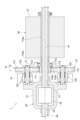
- FIG. 1 is a cross-sectional view showing a main portion of a transmission according to an embodiment of the present invention.
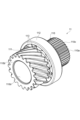
- FIG. 2 is a perspective view of the sun gear unit of FIG. 1 as viewed from the spline side.
- FIG. 3 is a perspective view of the sun gear unit of FIG. 1 as viewed from the sun gear side.
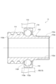
- FIG. 4 is an enlarged cross-sectional view of the sun gear unit of FIG.
- FIG. 5 is a diagram showing an example of a manner in which the sun gear shaft according to the embodiment is manufactured.
- FIG. 6 is a cross-sectional view of a sun gear shaft according to a modified example.
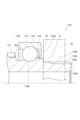
- FIG. 7 is an enlarged cross-sectional view of the vicinity of the shaft raceway surface for explaining how the shaft raceway surface and the sun gear are formed.
- FIG. 1 is a cross-sectional view showing a main portion of a transmission according to an embodiment of the present invention.
- FIG. 2 is a perspective view of the sun gear unit of FIG. 1 as
- FIG. 8 is an enlarged cross-sectional view of the shaft raceway surface and its surroundings of a sun gear unit according to a first modified example.
- FIG. 9 is an enlarged cross-sectional view of a sun gear unit according to a second modified example.
- FIG. 10 is a cross-sectional view showing a hardened layer provided on the surface of a sun gear unit according to a second modified example.
- 11(a) to 11(c) are enlarged cross-sectional views of a sun gear unit according to a third modified example.
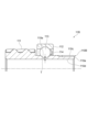
- FIG. 12 is a cross-sectional view showing a main portion of a transmission equipped with a sun gear shaft according to a modified example.
- the transmission 1 is configured as a reduction gear for an EV (Electric Vehicle) equipped with a drive unit 30 having an electric motor.
- the transmission 1 includes a planetary gear mechanism 10 and a differential gear unit 20.
- the transmission 1 also includes a housing that houses each mechanism, such as the planetary gear mechanism 10, although this is omitted in FIG. 1.
- the drive unit 30 constitutes an electric motor unit that serves as the drive source for the vehicle. More specifically, the drive unit 30 includes a motor rotor 31 and a rotor shaft 32. The motor rotor 31 constitutes the rotor of the electric motor. Although not shown in the figure, the drive unit 30 is equipped with components such as magnets that constitute an electric motor as a drive mechanism. The drive unit 30 may also be equipped with electronic components such as an inverter.
- the rotor shaft 32 is provided at the center of the motor rotor 31.
- the rotor shaft 32 is driven to rotate by the motor rotor 31.
- the rotor shaft 32 serves as the output shaft of the driving force (rotational force) of the drive unit 30.
- the rotor shaft 32 is connected to the planetary gear mechanism 10.
- the rotor shaft 32 has a cylindrical shape.
- a first drive shaft 41 passes through the inside of the rotor shaft 32.
- a rotor spline 32a is formed on the inner circumferential surface of the end of the rotor shaft 32 that is connected to the planetary gear mechanism 10.
- the planetary gear mechanism 10 of the transmission 1 reduces the speed of the rotational force transmitted from the rotor shaft 32 of the drive unit 30 and transmits it to the differential gear unit 20.
- the planetary gear mechanism 10 includes a sun gear unit 11, a plurality of planetary gear units 12, a carrier 13, and an outer gear 14.
- the sun gear unit 11 is connected to the rotor shaft 32 of the drive unit 30.
- the rotational force is transmitted to the sun gear unit 11 from the rotor shaft 32.
- the axis of rotation of the sun gear unit 11 is on the same line as the axis of rotation of the rotor shaft 32.
- the sun gear unit 11 has a sun gear 111. Details of the sun gear unit 11 will be described later.
- the multiple planetary gear units 12 are arranged around the sun gear 111 of the sun gear unit 11 at a predetermined interval from each other in the circumferential direction. Rotational force is transmitted to each of the multiple planetary gear units 12 from the sun gear 111.
- the planetary gear unit 12 comprises a first planetary gear (planetary gear) 121, a second planetary gear 122, and a planetary gear shaft 123.
- the first planetary gear 121 and the second planetary gear 122 are arranged on the same rotational axis and are connected to each other. In other words, the first planetary gear 121 and the second planetary gear 122 rotate integrally.
- the first planetary gear 121 has a larger diameter than the second planetary gear 122.
- the first planetary gear 121 meshes with the sun gear 111 of the sun gear unit 11.
- the planetary gear shaft 123 serves as the rotation axis of the first planetary gear 121 and the second planetary gear 122.
- the planetary gear shaft 123 rotatably supports the first planetary gear 121 and the second planetary gear 122.
- the carrier 13 supports the ends of the planetary gear shafts 123 of the multiple planetary gear units 12 on the drive unit 30 side.
- the rotation axis of the carrier 13 is on the same line as the rotation axis of the sun gear unit 11.
- the ends of the planetary gear shafts 123 of the multiple planetary gear units 12 opposite to the side supported by the carrier 13 are each supported by the differential case 21 of the differential gear unit 20.
- the outer gear 14 is annular and has a gear on its inner circumferential surface.
- the outer gear 14 is disposed so as to surround the second planetary gears 122 and meshes with each of the second planetary gears 122.
- the outer gear 14 is fixed to, for example, the housing of the transmission 1.
- the multiple planetary gear units 12 revolve around the sun gear unit 11 as the sun gear unit 11 rotates.
- the differential gear unit 20 rotates.
- the differential gear unit 20 receives rotational force from the planetary gear mechanism 10.
- the rotation axis of the differential gear unit 20 is on the same line as the rotation axis of the planetary gear mechanism 10 and the rotor shaft 32.
- the differential gear unit 20 includes a differential case 21 and a differential mechanism 22.
- the rotational force is transmitted to the differential case 21 from the planetary gear unit 12 of the planetary gear mechanism 10.
- the differential case 21 has a space inside.
- the differential mechanism 22 is provided in the differential case 21.
- the differential mechanism 22 is, for example, a differential mechanism of a vehicle differential gear unit equipped with a pinion gear, a side gear, etc.
- Various well-known mechanisms can be used as the differential mechanism 22.
- the differential case 21 is provided with a first insertion port h1 and a second insertion port h2 on the rotation axis of the sun gear unit 11.
- a first drive shaft (rotating shaft) 41 is inserted into the differential mechanism 22 via the first insertion port h1, and a second drive shaft 42 is inserted into the differential mechanism 22 via the second insertion port h2.
- the first drive shaft 41 and the second drive shaft 42 are each provided on the rotation axis of the sun gear unit 11.
- the sun gear unit 11 includes a sun gear shaft 110, a sun gear 111, an outer ring 112, a plurality of balls (rolling elements) 113, and a retainer 114.
- the sun gear shaft 110 is disposed on the rotation axis of the rotor shaft 32.
- the sun gear shaft 110 has a first end 110a connected to the rotor shaft 32 and a second end 110b opposite to the first end 110a.
- a rotational force is input from the rotor shaft 32 to the first end 110a.
- a sun gear spline (spline) 110c is formed on the outer peripheral surface of the first end 110a.
- the sun gear spline 110c meshes with the rotor spline 32a of the rotor shaft 32. This transmits a rotational force from the rotor shaft 32 to the sun gear unit 11.
- a sun gear 111 is provided on the outer peripheral surface of the second end 110b of the sun gear shaft 110.
- the sun gear 111 rotates integrally with the sun gear shaft 110.
- the sun gear 111 is provided integrally with the sun gear shaft 110.
- the sun gear 111 transmits the rotational force transmitted to the sun gear unit 11 to the first planetary gear 121 of the planetary gear unit 12.
- a shaft raceway surface 110e is formed on the outer peripheral surface of the sun gear shaft 110 between the first end 110a and the second end 110b. That is, the shaft raceway surface 110e is formed on the outer peripheral surface of the sun gear shaft 110 between the sun gear spline 110c and the sun gear 111.
- the shaft raceway surface 110e is provided over the entire circumferential area of the outer peripheral surface of the sun gear shaft 110.
- the shaft raceway surface 110e is a groove that extends in the circumferential direction of the sun gear shaft 110. In this embodiment, the cross-sectional shape of the shaft raceway surface 110e is approximately arc-shaped.
- the axial raceway surface 110e on the outer peripheral surface of the sun gear shaft 110 is formed at the raceway surface forming portion 110f (see FIG. 4) between the sun gear spline 110c and the sun gear 111.
- the raceway surface forming portion 110f is a portion of the sun gear shaft 110 that faces the inner peripheral surface of the outer ring 112.
- the outer diameter of the raceway surface forming portion 110f is larger than the outer diameter of the first end portion 110a where the sun gear spline 110c is formed.
- the outer diameter of the raceway surface forming portion 110f is smaller than the outer diameter of the sun gear 111.
- the size relationship between the raceway surface forming portion 110f and other portions is not limited to this relationship, and the size relationship may be reversed from that described here.
- the outer ring 112 is attached to a shaft support portion (support portion) 50 that supports the sun gear shaft 110.
- the shaft support portion 50 is formed by the carrier (support portion) 13 of the planetary gear mechanism 10.
- the shaft support portion 50 may also be formed by, for example, a part of a housing that houses the planetary gear mechanism 10, etc.
- the outer ring 112 is arranged to surround the axial raceway surface 110e formed on the sun gear shaft 110.
- An outer ring raceway surface 112a is formed on the inner peripheral surface of the outer ring 112.
- the outer ring raceway surface 112a is provided over the entire circumferential area of the inner peripheral surface of the outer ring 112.
- the outer ring raceway surface 112a is a groove extending in the circumferential direction of the outer ring 112.
- the cross-sectional shape of the outer ring raceway surface 112a is substantially arc-shaped.
- the outer ring raceway surface 112a of the outer ring 112 and the axial raceway surface 110e of the sun gear shaft 110 face each other.
- the multiple balls 113 are arranged between the outer ring raceway surface 112a of the outer ring 112 and the shaft raceway surface 110e of the sun gear shaft 110.
- the balls 113 are spherical.
- the cage 114 holds each of the multiple balls 113 between the outer ring raceway surface 112a and the shaft raceway surface 110e so that they can roll freely.
- the sun gear shaft 110 has a shaft through hole 110d that extends along the axis of the sun gear shaft 110.
- the first drive shaft 41 connected to the differential mechanism 22 of the differential gear unit 20 passes through the shaft through hole 110d.
- the rotation axis of the sun gear shaft 110 and the rotation axis of the first drive shaft 41 are on the same line.
- the sun gear shaft 110 is supported by the shaft support portion 50 via the balls 113 and the outer ring 112.
- the sun gear shaft 110 also functions as the inner ring of the bearing.
- the sun gear unit 11 can reduce the number of parts in the mechanism that supports the sun gear shaft 110, and can suppress a decrease in the support accuracy of the sun gear shaft 110 due to variations in part accuracy, etc. Therefore, in this sun gear unit 11, the sun gear shaft 110 can be supported stably and rotatably.
- an axial load may be applied to this sun gear unit 11.
- the sun gear shaft 110 also functions as the inner ring of the bearing, and the bearing portion is positioned, so there is no need to provide a retaining ring or spacer to prevent the inner ring from shifting.
- the sun gear shaft 110 also functions as the inner ring of the bearing, so there is no need to provide a separate inner ring of the bearing. This allows the sun gear unit 11 to be made smaller in the radial direction and lighter in weight.
- the first end 110a of the sun gear shaft 110 is provided with a sun gear spline 110c that meshes with the rotor spline 32a of the rotor shaft 32. This allows the sun gear unit 11 to more reliably transmit rotational force between the sun gear unit 11 and the rotor shaft 32, which is another rotating member, via the sun gear spline 110c.
- a shaft through hole 110d is provided on the inside of the sun gear shaft 110.
- this sun gear unit 11 other rotating shafts can be placed inside the sun gear shaft 110.
- a first drive shaft 41 connected to the differential gear unit 20 is placed in the shaft through hole 110d of the sun gear shaft 110. This allows the sun gear unit 11 to reduce the size of the device having the sun gear unit 11 (the transmission 1 in this embodiment).
- the sun gear unit 11 does not have an inner ring as a separate member, and does not require a retaining ring or spacer to prevent the inner ring from slipping. Since no space is required for a retaining ring, the axial length of the sun gear shaft 110 can be shortened.
- the inner ring of the bearing is held by a magnet chuck at its axial end face, and a raceway groove (raceway surface) is formed on the outer circumferential surface of the inner ring by a grinding shoe.
- the axial raceway surface 110e can be formed on the outer circumferential surface of the sun gear shaft 110 by a device similar to the device that forms the raceway groove on the inner ring of the bearing.
- the second end 110b of the sun gear shaft 110 is held by a magnet chuck G1.
- the grinding shoe G2 forms the axial raceway surface 110e on the raceway surface forming portion 110f on the outer circumferential surface of the sun gear shaft 110.
- the axial raceway surface 110e can be formed on the raceway surface forming portion 110f of the sun gear shaft 110 by a device similar to a device used to form the inner ring of a general bearing.
- the inner ring of the bearing When a bearing having an inner ring is attached to the sun gear shaft, the inner ring of the bearing may be butted against the end of the sun gear to position the inner ring.
- the sun gear and the inner ring are related to each other, which places restrictions on the installation positions of the two and the size of the sun gear, etc.
- the sun gear shaft 110 also functions as the inner ring of the bearing. For this reason, in the sun gear unit 11, there is no need to position the inner ring using the sun gear 111. In other words, there is no relationship between the sun gear 111 and the shaft raceway surface 110e that functions as the inner ring of the bearing, and there are no restrictions on the installation positions of the two and the size of the sun gear 111, etc.
- a gap is provided between the sun gear 111 and the outer ring 112 and the balls 113 in the axial direction of the sun gear shaft 110.
- a large gap of a desired size may be provided between the sun gear 111 and the outer ring 112 and the balls 113 in the axial direction of the sun gear shaft 110.
- a ball insertion jig G3 used when placing the balls 113 between the outer ring 112 and the axial raceway surface 110e may be placed in the gap between the sun gear 111 and the outer ring 112 and the balls 113. In this case, the ball insertion jig G3 is placed in the gap between the sun gear 111 and the outer ring 112.
- the ball insertion jig G3 functions as a jig that prevents the balls 113 from falling out from between the outer ring 112 and the axial raceway surface 110e when the balls 113 are being placed.
- the sun gear unit 11 can increase the design freedom by having no correlation between the sun gear 111 and the axial raceway surface 110e.
- the sun gear unit 11 can improve the assembly ease of the sun gear unit 11 because the ball insertion jig G3 can be placed in the gap between the sun gear 111 and the outer ring 112.
- the width of the sun gear (the axial length of the sun gear shaft) may be extended in order to position the inner ring by abutting it against the sun gear.
- the width of the sun gear 111 can be set to only the width necessary for transmitting rotational force.
- the width of the sun gear 111 is not unnecessarily extended, so that the weight can be reduced.
- the width of the sun gear 111 is not unnecessarily extended, so that the processing time for forming the sun gear 111 can be shortened, and the life of the tools for forming the sun gear 111 can be extended.
- the axial raceway surface 110e may be ground by a grinding wheel G4.
- the installation positions of the sun gear 111 and the axial raceway surface 110e can be adjusted so that the tool forming the axial raceway surface 110e, such as the grinding wheel G4, does not interfere with the sun gear 111.
- the tooth surface of the sun gear 111 may be ground by a tooth grinding wheel.
- the installation positions of the sun gear 111 and the axial raceway surface 110e can be adjusted so that the tool forming the sun gear 111, such as the tooth grinding wheel, does not interfere with the groove shoulder of the axial raceway surface 110e.
- the sun gear unit 11 can increase the degree of freedom in designing the sun gear 111 and the axial raceway surface 110e, and the sun gear shaft 110 including the sun gear 111 and the axial raceway surface 110e can be easily formed.
- the sun gear 111 is provided integrally with the sun gear shaft 110.
- the axial raceway surface 110e is formed on the outer peripheral surface (raceway surface forming portion 110f) of the sun gear shaft 110.
- the sun gear shaft 110, the sun gear 111, and the axial raceway surface 110e are provided integrally. Therefore, when forming the sun gear 111 and the axial raceway surface 110e, the sun gear 111 and the axial raceway surface 110e can be formed using the same machining reference. As a result, the sun gear unit 11 can ensure the concentricity of the sun gear 111 and the axial raceway surface 110e with greater precision.
- the transmission 1 includes a planetary gear mechanism 10 having the above-mentioned sun gear unit 11, and a differential gear unit 20 to which rotational force is transmitted from the planetary gear mechanism 10. In this way, the transmission 1 including the sun gear unit 11 can stably support the sun gear shaft 110 for rotation.
- the sun gear unit 11A includes a sun gear shaft 110A instead of the sun gear shaft 110 in the embodiment.
- the sun gear shaft 110A has a first groove shoulder surface (groove shoulder surface) S1 and a second groove shoulder surface S2 adjacent to the shaft raceway surface 110e so as to sandwich the shaft raceway surface 110e in the axial direction of the sun gear shaft 110A.
- the first groove shoulder surface S1 is adjacent to the shaft raceway surface 110e on the first end 110a side of the shaft raceway surface 110e.
- the second groove shoulder surface S2 is adjacent to the shaft raceway surface 110e on the sun gear 111 side (the second end 110b side opposite to the first end 110a) of the shaft raceway surface 110e.
- the first groove shoulder surface S1 and the second groove shoulder surface S2 are surfaces facing radially outward of the sun gear shaft 110A and extend in an annular shape along the circumferential direction of the sun gear shaft 110A.
- the first groove shoulder surface S1 and the second groove shoulder surface S2 are cylindrical surfaces whose axis is the rotational axis of the sun gear shaft 110A.
- the outer diameter (diameter of the cylindrical surface) of the first groove shoulder surface S1 and the outer diameter (diameter of the cylindrical surface) of the second groove shoulder surface S2 are different from each other.
- the outer diameter of the first groove shoulder surface S1 is larger than the outer diameter of the second groove shoulder surface S2.
- the sun gear shaft 110A also has a first groove shoulder surface forming portion (groove shoulder surface forming portion) 110g and an engagement portion 110h.
- the first groove shoulder surface forming portion 110g is a portion of the sun gear shaft 110A closer to the first end 110a than the axial raceway surface 110e.
- the first groove shoulder surface forming portion 110g has a first groove shoulder surface S1 on its outer circumferential surface adjacent to the axial raceway surface 110e at a position closer to the first end 110a than the axial raceway surface 110e.
- the engagement portion 110h is adjacent to the first groove shoulder surface forming portion 110g at a position closer to the first end 110a than the first groove shoulder surface forming portion 110g.
- a sun gear spline 110c is formed in the portion of the outer circumferential surface of the first groove shoulder surface forming portion 110g on the first end 110a side.
- Another member B is engaged on the outer circumferential surface of the engagement portion 110h. There are no particular limitations on the member B that is fitted into the fitting portion 110h.
- the size of the first groove shoulder surface forming portion 110g is larger than the size of the fitting portion 110h.
- a step D is formed at the connection portion between the first groove shoulder surface forming portion 110g and the fitting portion 110h.
- the first groove shoulder surface S1 has a larger diameter than the second groove shoulder surface S2. Therefore, the ball 113 arranged between the outer ring 112 and the shaft raceway surface 110e is less likely to ride up on the first groove shoulder surface S1 on the larger diameter side than the second groove shoulder surface S2 on the smaller diameter side. In this way, the sun gear unit 11A can receive the axial load while suppressing the ball 113 from riding up on the groove shoulder surface on the larger diameter side by making the outer diameters of the first groove shoulder surface S1 and the second groove shoulder surface S2 different from each other.
- first groove shoulder surface S1 has a larger diameter than the second groove shoulder surface S2, but the second groove shoulder surface S2 may have a larger diameter than the first groove shoulder surface S1.
- the outer diameters of the first groove shoulder surface S1 and the second groove shoulder surface S2 can be set according to the direction of the axial load to be received.
- a step D is formed on the outer circumferential surface of the sun gear shaft 110A between the first groove shoulder surface forming portion 110g and the fitting portion 110h (the connecting portion). This allows the sun gear unit 11A to position the member B fitted into the fitting portion 110h by abutting the member B fitted into the fitting portion 110h against this step D.
- the sun gear unit 11B includes a sun gear shaft 110B instead of the sun gear shaft 110 in the embodiment.
- a hardened layer F is provided on the surface portion of the sun gear shaft 110B.
- the portion provided with the hardened layer F has a higher hardness than the portion of the sun gear shaft 110B other than the hardened layer F.
- the hardened layer F may be provided on the surface of the sun gear shaft 110B by a carburizing process.
- the method of providing the hardened layer F is not limited to the carburizing process.
- the hardened layer F is provided from the surface of the sun gear shaft 110B to a predetermined depth position.
- the inner circumferential surface of the shaft through hole 110d of the sun gear shaft 110B is also the surface of the sun gear shaft 110B. Therefore, in addition to the surface portion facing radially outward of the sun gear shaft 110B, the hardened layer F is also provided on the inner circumferential surface portion of the shaft through hole 110d of the sun gear shaft 110B.
- the thickness L of the hardened layer F is greater than half the thickness of the axial raceway surface 110e of the sun gear shaft 110B.
- the axial raceway surface 110e is grooved.
- the thickness L of the hardened layer F is greater than half the thickness of the groove bottom of the grooved axial raceway surface 110e.
- the thickness of the groove bottom of the axial raceway surface 110e is the thickness T of the smallest diameter part of the axial raceway surface 110e, as shown in FIG. 9. This thickness T is the length from the smallest diameter part of the axial raceway surface 110e to the shaft through hole 110d.
- the thickness L of the hardened layer F may be a target value (design value) of the thickness of the hardened layer F when performing a process to provide the hardened layer F on the sun gear shaft 110B.
- the sun gear shaft 110B has a hardened layer F at the bottom of the groove of the axial raceway surface 110e across the entire radial thickness T. This allows the sun gear shaft 110B to further improve the internal hardness of the axial raceway surface 110e.
- This hardened layer F may also be provided on the sun gear 111. This allows the internal hardness of the axial raceway surface 110e to be improved while ensuring the toughness of the sun gear 111.
- the sun gear unit 11C includes an outer ring 112C instead of the outer ring 112 in the embodiment.
- a recess (engagement portion) 112b is provided on the outer peripheral surface of the outer ring 112C.
- the recess 112b may be provided over the entire circumferential area of the outer ring 112C, or may be provided only in a portion of the circumferential area.
- the recess 112b is provided on the outer peripheral surface of the outer ring 112C at the end of the outer ring 112C on the sun gear 111 side in the axial direction.
- the shaft support part 50 which supports the outer ring 112C, is provided with a convex part 50a that protrudes toward the outer ring 112C.
- the convex part 50a of the shaft support part 50 is fitted into the concave part 112b of the outer ring 112C.
- the concave part 112b of the outer ring 112C engages with the shaft support part 50 in the axial direction of the sun gear shaft 110.
- the concave part 112b provided in the outer ring 112C can suppress misalignment between the outer ring 112C and the shaft support part 50 in the axial direction of the sun gear shaft 110.
- the recess 112b of the outer ring 112C may engage with the shaft support portion 50 via an engaging member W such as a retaining ring.
- an engaging member W such as a retaining ring.
- a recess 50b is provided on the inner peripheral surface of the shaft support portion 50 (the mounting surface of the outer ring 112C).
- the engaging member W fits into and engages with the recess 112b of the outer ring 112C and the recess 50b of the shaft support portion 50.
- the recess 112b of the outer ring 112C into which the engaging member W is fitted may be provided on the outer peripheral surface of the outer ring 112C in a portion other than both ends in the axial direction.
- the recess 112b of the outer ring 112C into which the engaging member W is fitted may be provided on the outer peripheral surface of the outer ring 112C at the end in the axial direction.
- the outer peripheral surface of the outer ring 112C is provided with a recess 112b as an engagement portion that engages with the shaft support portion 50.
- the outer peripheral surface of the outer ring 112C may be provided with a protrusion as an engagement portion that engages with the shaft support portion 50.
- the shape of the engagement portion (e.g., recess 112b, protrusion) provided on the outer ring 112C is not limited.
- the engagement portion provided on the outer ring 112C may directly engage with the shaft support portion 50 as shown in FIG. 11(a), or may engage with the shaft support portion 50 via an engagement member W or the like as shown in FIG. 11(b).
- the sun gear spline 110c formed on the first end 110a of the sun gear shaft 110, etc. is not limited to being formed on the outer circumferential surface of the sun gear shaft 110, etc.
- the sun gear spline formed on the first end 110a may be formed on the inner circumferential surface of the sun gear shaft 110, etc. In this case, it is sufficient that the rotor spline is formed on the outer circumferential surface of the rotor shaft 32.
- the sun gear shaft 110, etc. are not limited to a configuration having a sun gear spline 110c at the first end 110a.
- the rotational force of the drive unit 30 may be directly transmitted to the first end of the sun gear shaft.
- the sun gear unit 11D has a sun gear shaft 110D instead of the sun gear shaft 110 in the embodiment.
- the configuration other than the sun gear shaft 110D is the same as that of the sun gear unit 11 described above.
- One end of the sun gear shaft 110D is provided with a first end 110a to which rotational force is input from the drive unit 30.
- the first end 110a extends to the inside of the motor rotor 31.
- the motor rotor 31 of the drive unit 30 is attached to the first end 110a.
- the sun gear shaft 110D rotates integrally with the motor rotor 31.
- the sun gear shaft 110D combines the functions of the sun gear shaft 110 and the rotor shaft 32 in the above-mentioned embodiment.
- the rotational force of the drive unit 30 is directly input to the first end 110a of the sun gear shaft 110D.
- the sun gear shaft 110D has an axial raceway surface 110e between the first end 110a and the second end 110b, similar to the sun gear shaft 110 in the embodiment.
- the sun gear shaft 110D is rotatably supported by the shaft support portion 50 via balls 113 and a retainer 114.
- a sun gear 111 is provided at the second end 110b. Even in this case, the sun gear unit 11D including the sun gear shaft 110D can achieve the same effect as the sun gear unit 11 in the embodiment.
- the sun gear shaft 110, etc. are not limited to being rotatably supported by the balls 113.
- the sun gear shaft 110, etc. may be rotatably supported by "rollers” as rolling elements other than the balls 113.
- the shaft raceway surface 110e formed on the outer peripheral surface of the sun gear shaft 110, etc. and the outer ring raceway surface 112a formed on the inner peripheral surface of the outer ring 112 may be formed in a shape corresponding to the rollers as rolling elements.
- the configuration of the planetary gear mechanism 10 is not limited to the above configuration.
- the planetary gear mechanism 10 may at least include the above-mentioned sun gear unit 11, etc., and a planetary gear unit that rotates around the sun gear unit 11, etc.
- the planetary gear mechanism 10 has been shown to transmit a rotational force from the drive unit 30 to the sun gear unit 11, etc. That is, the rotational force is transmitted to the first end 110a of the sun gear shaft 110, etc. of the sun gear unit 11, etc. Without being limited to this, the rotational force may be transmitted from the first end 110a of the sun gear shaft 110, etc. to another mechanism. That is, the rotational force may be output from the first end 110a of the sun gear shaft 110, etc. of the sun gear unit 11, etc.
- the planetary gear mechanism 10 is not limited to decelerating the rotational speed.
- the planetary gear mechanism 10 may also increase the rotational speed. In this case, the transmission 1 functions as a speed increaser.
Landscapes
- Engineering & Computer Science (AREA)
- General Engineering & Computer Science (AREA)
- Mechanical Engineering (AREA)
- Retarders (AREA)
Abstract
遊星歯車機構のサンギヤユニットは、回転力を入出力する第1端部、及び第1端部に対して反対側の第2端部を有し、外周面に軸軌道面が形成されたサンギヤシャフトと、第2端部に設けられ、遊星歯車機構の遊星ギヤにかみ合うサンギヤと、サンギヤシャフトを支持する支持部に取り付けられ、軸軌道面を囲むように設けられると共に、内周面に外輪軌道面が形成された外輪と、軸軌道面と外輪軌道面との間に配置された複数の転動体と、を備える。
Description
本開示は、遊星歯車機構のサンギヤユニット、及び変速機に関する。
例えば、特許文献1に記載されているように、駆動ユニットの駆動軸の回転速度を減速させて出力する変速機(減速機)がある。この変速機は、ギヤが設けられた回転軸を複数備え、駆動軸の回転を複数の回転軸に順次伝達することによって、回転速度を減速させている。また、遊星歯車機構を用いて回転速度を変速する変速機がある。
ここで、遊星歯車機構を備える変速機では、遊星歯車機構のサンギヤユニットのサンギヤシャフトが、軸受を介して支持部に回転可能に支持されている。このサンギヤシャフトにブレが生じると、回転性能や耐久性等が低下する可能性が考えられる。
そこで、本開示は、サンギヤシャフトを安定して回転可能に支持可能な遊星歯車機構のサンギヤユニット、及び変速機を提供することを目的とする。
本開示に係るサンギヤユニットは、[1]「遊星歯車機構のサンギヤユニットであって、回転力を入出力する第1端部と、前記第1端部に対して反対側の第2端部と、を有し、前記第1端部と前記第2端部との間の外周面に軸軌道面が形成されたサンギヤシャフトと、前記第2端部に設けられ、前記遊星歯車機構の遊星ギヤにかみ合うサンギヤと、前記サンギヤシャフトを支持する支持部に取り付けられ、前記軸軌道面を囲むように設けられると共に、内周面に外輪軌道面が形成された外輪と、前記軸軌道面と前記外輪軌道面との間に配置された複数の転動体と、を備えるサンギヤユニット。」である。
このサンギヤユニットでは、サンギヤシャフトが、転動体及び外輪を介して支持部に支持される。つまり、サンギヤシャフトは、軸受の内輪の機能を兼ねている。このように、このサンギヤユニットは、サンギヤシャフトを支持する機構の部品点数を少なくすることができ、部品精度のばらつき等によるサンギヤシャフトの支持精度の低下を抑制できる。したがって、このサンギヤユニットでは、サンギヤシャフトを安定して回転可能に支持することができる。
本開示に係るサンギヤユニットは、[2]「前記第1端部の外周面又は内周面には、スプラインが形成されている、上記[1]に記載のサンギヤユニット。」であってもよい。これにより、サンギヤユニットは、スプラインを介して、他の回転部材との間での回転力の伝達をより確実に行うことができる。
本開示に係るサンギヤユニットは、[3]「前記サンギヤシャフトは、前記軸軌道面よりも前記第1端部側の位置において、前記軸軌道面に隣接する溝肩面を外周面に有する溝肩面形成部と、前記溝肩面形成部よりも前記第1端部側の位置において、前記溝肩面形成部に隣接する嵌込部と、を有し、前記サンギヤシャフトの径方向における前記溝肩面形成部の大きさは、前記サンギヤシャフトの径方向における前記嵌込部の大きさよりも大きい、上記[1]又は[2]に記載のサンギヤユニット。」であってもよい。この場合、サンギヤシャフトの外周面において、溝肩面形成部と嵌込部との間に段差が形成される。これにより、サンギヤユニットは、嵌込部に嵌め込んだ部材をこの段差部分に当接させることによって、嵌込部に嵌め込む部材の位置決めを行うことができる。
本開示に係るサンギヤユニットは、[4]「前記サンギヤシャフトは、前記サンギヤシャフトの軸線方向において前記軸軌道面を挟み込むように前記軸軌道面に隣接する第1溝肩面及び第2溝肩面を有し、前記第1溝肩面及び前記第2溝肩面は、それぞれ前記サンギヤシャフトの周方向に沿って延在する円環状を呈し、前記第1溝肩面の外径と前記第2溝肩面の外径とは互いに異なっている、上記[1]~[3]のいずれか一つに記載のサンギヤユニット。」であってもよい。軸軌道面に配置された転動体は、第1溝肩面及び第2溝肩面のうち、小径側の溝肩面よりも大径側の溝肩面に乗り上げにくくなる。このように、サンギヤユニットは、第1溝肩面及び第2溝肩面の外径を互いに異ならせることによって、転動体が溝肩面に乗り上げることを抑制しつつ、アキシャル荷重を受け止めることができる。
本開示に係るサンギヤユニットは、[5]「前記外輪の外周面には、前記サンギヤシャフトの軸線方向において前記支持部と係合する係合部が設けられている、上記[1]~[4]のいずれか一つに記載のサンギヤユニット。」であってもよい。この場合、外輪に設けられた係合部によって、サンギヤシャフトの軸方向における外輪と支持部とのずれを抑制できる。
本開示に係るサンギヤユニットは、[6]「前記サンギヤシャフトの軸線方向において、前記サンギヤと前記外輪及び前記転動体との間には、隙間が設けられている、上記[1]~[5]のいずれか一つに記載のサンギヤユニット。」であってもよい。この場合、サンギヤユニットでは、設計の自由度を高めたり、転動体及び外輪周りの組み立て性を向上させたりすることができる。
本開示に係るサンギヤユニットは、[7]「前記サンギヤシャフトには、当該サンギヤシャフトの軸線に沿って延在すると共に、回転軸が通される軸貫通孔が設けられている、上記[1]~[6]のいずれか一つに記載のサンギヤユニット。」であってもよい。このように、サンギヤシャフトの内側に他の回転軸が配置することができるため、サンギヤユニットを用いた装置の小型化を図ることができる。
本開示に係るサンギヤユニットは、[8]「前記サンギヤシャフトの表面部分には硬化層が設けられており、前記硬化層が設けられた部分は、前記サンギヤシャフトの前記硬化層以外の部分よりも硬度が高く、前記硬化層の厚さは、前記サンギヤシャフトの前記軸軌道面における肉厚の半分よりも大きい、上記[7]に記載のサンギヤユニット。」であってもよい。ここで、サンギヤシャフトの軸貫通孔の内周面も、サンギヤシャフトの表面となる。このため、サンギヤシャフトの径方向の外側を向く面の部分に加え、サンギヤシャフトの軸貫通孔の内周面の部分にも硬化層が設けられている。硬化層の厚さを軸軌道面における肉厚の半分よりも大きくすることにより、サンギヤシャフトの軸軌道面の部分では、径方向の肉厚の全域にわたって硬化層が設けられた状態となる。これにより、サンギヤユニットは、軸軌道面における内部硬さをより一層向上させることができる。
本開示に係る変速機は、[9]「上記[7]又は[8]に記載のサンギヤユニットを有する遊星歯車機構と、前記遊星歯車機構から回転力が伝達されるデファレンシャルケースを有すると共に、前記デファレンシャルケース内に差動機構が設けられたデファレンシャルギヤユニットと、を備え、前記軸貫通孔には、前記回転軸として、前記差動機構に接続されるドライブシャフトが通される、変速機。」である。
この変速機では、サンギヤシャフトが、転動体及び外輪を介して支持部に支持される。つまり、サンギヤシャフトは、軸受の内輪の機能を兼ねている。このように、このサンギヤユニットは、サンギヤシャフトを支持する機構の部品点数を少なくすることができ、部品精度のばらつき等によるサンギヤシャフトの支持精度の低下を抑制できる。したがって、このサンギヤユニットを備える変速機では、サンギヤシャフトを安定して回転可能に支持することができる。また、この変速機では、サンギヤシャフトの内側にデファレンシャルギヤに接続されるドライブシャフトを配置することができる。これにより、変速機の小型化を図ることができる。
本開示によれば、サンギヤシャフトを安定して回転可能に支持することができる。
以下、本開示の実施形態について図面を参照しながら説明する。なお、各図において、同一又は相当する要素同士には同一符号を付し、重複する説明を省略する。また、以下では、本開示に係る変速機として、駆動ユニットの回転速度を減速する減速機を用いて説明する。
図1に示されるように、変速機1は、本実施形態においては一例として、電動モータを有する駆動ユニット30が搭載されたEV(Electric Vehicle)用の減速機として構成されている。変速機1は、遊星歯車機構10、及びデファレンシャルギヤユニット20を備えている。また、変速機1は、図1では省略されているが、遊星歯車機構10等の各機構を収容する筐体を備えている。
駆動ユニット30は、車両の駆動源となる電動モータユニットを構成する。より詳細には、駆動ユニット30は、モータロータ31、ロータシャフト32を含んでいる。モータロータ31は、電動モータのロータを構成する。図示は省略するが、駆動ユニット30は、駆動機構として、電動モータを構成するマグネット等の部品を備えている。また、駆動ユニット30は、インバータ等の電子部品を備えていてもよい。
ロータシャフト32は、モータロータ31の中心部分に設けられている。ロータシャフト32は、モータロータ31によって回転駆動される。ロータシャフト32は、駆動ユニット30の駆動力(回転力)の出力軸となる。ロータシャフト32は、遊星歯車機構10に接続される。ロータシャフト32は、円筒状を呈している。ロータシャフト32の内側には、第1ドライブシャフト41が通される。ロータシャフト32において、遊星歯車機構10に接続される側の端部の内周面には、ロータスプライン32aが形成されている。
変速機1の遊星歯車機構10は、駆動ユニット30のロータシャフト32から伝達された回転力を減速させて、デファレンシャルギヤユニット20に伝達する。遊星歯車機構10は、サンギヤユニット11、複数の遊星ギヤユニット12、キャリア13、及びアウターギヤ14を含んでいる。サンギヤユニット11は、駆動ユニット30のロータシャフト32に連結される。サンギヤユニット11には、ロータシャフト32から回転力が伝達される。サンギヤユニット11の回転軸線は、ロータシャフト32の回転軸線と同じ線上となっている。サンギヤユニット11は、サンギヤ111を有している。サンギヤユニット11の詳細については、後述する。
複数の遊星ギヤユニット12は、サンギヤユニット11のサンギヤ111の周りに、周方向において互いに所定の間隔を空けて配置されている。複数の遊星ギヤユニット12のそれぞれは、サンギヤ111から回転力が伝達される。遊星ギヤユニット12は、第1遊星ギヤ(遊星ギヤ)121、第2遊星ギヤ122、及び遊星ギヤシャフト123を備えている。第1遊星ギヤ121と第2遊星ギヤ122とは、互いに同じ回転軸線上に配置され、互いに連結されている。つまり、第1遊星ギヤ121と第2遊星ギヤ122とは、一体的に回転する。第1遊星ギヤ121は、第2遊星ギヤ122よりも大径となっている。第1遊星ギヤ121は、サンギヤユニット11のサンギヤ111にかみ合う。遊星ギヤシャフト123は、第1遊星ギヤ121及び第2遊星ギヤ122の回転軸となる。遊星ギヤシャフト123は、第1遊星ギヤ121及び第2遊星ギヤ122を回転可能に支持する。
キャリア13は、複数の遊星ギヤユニット12の遊星ギヤシャフト123において、駆動ユニット30側の端部をそれぞれ支持する。キャリア13の回転軸線は、サンギヤユニット11の回転軸線と同じ線上となっている。複数の遊星ギヤユニット12の遊星ギヤシャフト123において、キャリア13に支持される側に対して反対側の端部は、デファレンシャルギヤユニット20のデファレンシャルケース21によってそれぞれ支持される。
アウターギヤ14は、環状を呈し、内周面にギヤを有する。アウターギヤ14は、複数の第2遊星ギヤ122を囲むように配置され、複数の第2遊星ギヤ122のそれぞれとかみ合っている。本実施形態においてアウターギヤ14は、例えば、変速機1の筐体等に固定されている。
これにより、複数の遊星ギヤユニット12は、サンギヤユニット11が回転することによって、サンギヤユニット11の周りを周回する。遊星ギヤユニット12がサンギヤユニット11の周りを周回することに伴って、デファレンシャルギヤユニット20が回転する。
デファレンシャルギヤユニット20は、遊星歯車機構10から回転力が伝達される。デファレンシャルギヤユニット20の回転軸線は、遊星歯車機構10及びロータシャフト32の回転軸線と同じ線上となっている。デファレンシャルギヤユニット20は、デファレンシャルケース21、及び差動機構22を備えている。
デファレンシャルケース21には、遊星歯車機構10の遊星ギヤユニット12から、回転力が伝達される。デファレンシャルケース21は、内部に空間を有している。
差動機構22は、デファレンシャルケース21内に設けられる。差動機構22は、例えば、ピニオンギヤ及びサイドギヤ等を備える車両用デファレンシャルギヤユニットの差動機構である。差動機構22としては、周知の種々の機構を用いることができる。デファレンシャルケース21には、サンギヤユニット11の回転軸線上に、第1差込口h1及び第2差込口h2が設けられている。差動機構22には、第1差込口h1を介して第1ドライブシャフト(回転軸)41と、第2差込口h2を介して第2ドライブシャフト42と、が差し込まれている。第1ドライブシャフト41及び第2ドライブシャフト42のそれぞれは、サンギヤユニット11の回転軸線上に設けられている。
次に、サンギヤユニット11の詳細について説明する。図2~図4に示されるように、サンギヤユニット11は、サンギヤシャフト110、サンギヤ111、外輪112、複数の玉(転動体)113、及び保持器114を備えている。サンギヤシャフト110は、ロータシャフト32の回転軸線上に配置されている。サンギヤシャフト110は、ロータシャフト32に接続される第1端部110aと、第1端部110aに対して反対側の第2端部110bと、を有している。第1端部110aには、ロータシャフト32から回転力が入力される。本実施形態において、第1端部110aの外周面には、サンギヤスプライン(スプライン)110cが形成されている。サンギヤスプライン110cは、ロータシャフト32のロータスプライン32aにかみ合っている。これにより、ロータシャフト32からサンギヤユニット11に回転力が伝達される。
サンギヤシャフト110の第2端部110bの外周面には、サンギヤ111が設けられている。サンギヤ111は、サンギヤシャフト110と一体に回転する。本実施形態において、サンギヤ111は、サンギヤシャフト110と一体に設けられている。サンギヤ111は、サンギヤユニット11に伝達された回転力を、遊星ギヤユニット12の第1遊星ギヤ121に伝達する。
サンギヤシャフト110の外周面において、第1端部110aと第2端部110bとの間には、軸軌道面110eが形成されている。つまり、軸軌道面110eは、サンギヤシャフト110の外周面において、サンギヤスプライン110cとサンギヤ111との間に形成されている。軸軌道面110eは、サンギヤシャフト110の外周面の周方向の全域にわたって設けられている。軸軌道面110eは、サンギヤシャフト110周方向に延びる溝である。本実施形態において、軸軌道面110eの断面形状は、略円弧状を呈している。
なお、サンギヤシャフト110の外周面において軸軌道面110eは、サンギヤスプライン110cとサンギヤ111との間の軌道面形成部110f(図4参照)に形成される。軌道面形成部110fは、サンギヤシャフト110のうち、外輪112の内周面に対向する部位である。本実施形態においては、一例として、軌道面形成部110fの外径は、サンギヤスプライン110cが形成される第1端部110aの外径よりも大きい。本実施形態においては、一例として、軌道面形成部110fの外径は、サンギヤ111の外径よりも小さい。但し、軌道面形成部110fと他の部位との大小関係は、この関係に限定されず、ここで説明した関係と大小が逆になっていてもよい。
外輪112は、サンギヤシャフト110を支持するシャフト支持部(支持部)50に取り付けられている。本実施形態においてシャフト支持部50は、遊星歯車機構10のキャリア(支持部)13によって構成されている。但し、シャフト支持部50は、例えば、遊星歯車機構10等を収容する筐体の一部によって構成されていてもよい。
外輪112は、サンギヤシャフト110に形成された軸軌道面110eを囲むように設けられている。外輪112の内周面には、外輪軌道面112aが形成されている。外輪軌道面112aは、外輪112の内周面の周方向の全域にわたって設けられている。外輪軌道面112aは、外輪112の周方向に延びる溝である。本実施形態において、外輪軌道面112aの断面形状は、略円弧状を呈している。外輪112の外輪軌道面112aと、サンギヤシャフト110の軸軌道面110eと、は対向している。
複数の玉113は、外輪112の外輪軌道面112aと、サンギヤシャフト110の軸軌道面110eと、の間に配置されている。玉113は、球状を呈している。保持器114は、外輪軌道面112aと軸軌道面110eとの間において、複数の玉113のそれぞれを転動自在に保持する。
サンギヤシャフト110には、サンギヤシャフト110の軸線に沿って延在する軸貫通孔110dが設けられている。軸貫通孔110dには、デファレンシャルギヤユニット20の差動機構22に接続された第1ドライブシャフト41が通されている。つまり、サンギヤシャフト110の回転軸線と、第1ドライブシャフト41の回転軸線とは、互いに同じ線上となっている。
以上のように、この遊星歯車機構10のサンギヤユニット11では、サンギヤシャフト110が、玉113及び外輪112を介してシャフト支持部50に支持される。つまり、サンギヤシャフト110は、軸受の内輪の機能を兼ねている。このように、このサンギヤユニット11は、サンギヤシャフト110を支持する機構の部品点数を少なくすることができ、部品精度のばらつき等によるサンギヤシャフト110の支持精度の低下を抑制できる。したがって、このサンギヤユニット11では、サンギヤシャフト110を安定して回転可能に支持することができる。
また、このサンギヤユニット11には、アキシャル荷重が加わることがある。例えば、サンギヤシャフトが内輪を有する軸受によって支持されている場合、内輪のずれ防止のために止め輪をサンギヤシャフトに取り付けたり、内輪をサンギヤ等に突き当てるためのスペーサをサンギヤシャフトに取り付けたりする必要が生じる。しかしながら、このサンギヤユニット11では、サンギヤシャフト110が軸受の内輪の機能を兼ねており、軸受部分の位置決めがなされるため、内輪のずれを防止するための止め輪又はスペーサ等を設けることが不要となる。
本実施形態に係るサンギヤユニット11では、サンギヤシャフト110が軸受の内輪の機能を兼ねているため、軸受の内輪を別途設ける必要が無い。このため、サンギヤユニット11では、径方向の小型化、及び軽量化を図ることができる。
サンギヤシャフト110の第1端部110aには、ロータシャフト32のロータスプライン32aにかみ合うサンギヤスプライン110cが設けられている。これにより、サンギヤユニット11は、サンギヤスプライン110cを介して、他の回転部材であるロータシャフト32との間での回転力の伝達をより確実に行うことができる。
サンギヤシャフト110の内側には、軸貫通孔110dが設けられている。このサンギヤユニット11では、サンギヤシャフト110の内側に他の回転軸を配置することができる。本実施形態においては、サンギヤシャフト110の軸貫通孔110dには、デファレンシャルギヤユニット20に接続される第1ドライブシャフト41が配置されている。これにより、サンギヤユニット11では、サンギヤユニット11を有する装置(本実施形態では変速機1)の小型化を図ることができる。
なお、上述したように、サンギヤユニット11には、そもそも内輪を別部材として有しておらず、内輪のずれを防止するための止め輪又はスペーサ等も不要である。止め輪等を設けるスペースが不要となる分、サンギヤシャフト110の軸方向の長さを短くすることができる。ここで、一般的に、軸受の内輪は、内輪の軸方向の端面がマグネットチャックによって保持された状態で、研削用のシューによって内輪の外周面に軌道溝(軌道面)が形成される。例えば、サンギヤシャフト110の長さが短い場合、軸受の内輪に軌道溝を形成する装置と同様の装置によって、サンギヤシャフト110の外周面に軸軌道面110eを形成することができる。具体的には、図5に示されるように、例えば、サンギヤシャフト110の第2端部110bを、マグネットチャックG1によって保持する。サンギヤシャフト110がマグネットチャックG1によって保持された状態で、研削用のシューG2によって、サンギヤシャフト110の外周面の軌道面形成部110fに軸軌道面110eを形成する。このように、サンギヤシャフト110の軌道面形成部110fに対して、一般的な軸受の内輪を形成する装置と同様の装置によって軸軌道面110eを形成することができる。
ここで、内輪を有する軸受をサンギヤシャフトに取り付ける場合、軸受の内輪をサンギヤの端部に突き当てて、内輪の位置決めをすることがある。この場合、サンギヤと内輪とが互いに関連性を有することとなり、両者の設置位置、及びサンギヤの大きさ等に制約が生じる。一方、本実施形態に係るサンギヤユニット11では、サンギヤシャフト110が軸受の内輪の機能を兼ねている。このため、サンギヤユニット11では、サンギヤ111によって内輪の位置決めを行う必要が無い。つまり、サンギヤ111と軸受の内輪として機能する軸軌道面110eとに関連性が無く、両者の設置位置、及びサンギヤ111の大きさ等に制約がない。
このため、図4に示されるように、サンギヤシャフト110の軸線方向において、サンギヤ111と外輪112及び玉113との間には、隙間が設けられている。また、図6に示されるように、サンギヤシャフト110の軸線方向において、サンギヤ111と外輪112及び玉113との間に所望の大きさの大きな隙間を設けてもよい。図6に示されるように、サンギヤ111と外輪112及び玉113との隙間には、外輪112と軸軌道面110eとの間に玉113を配置する際に用いられる玉入れ治具G3が配置可能であってもよい。この場合、サンギヤ111と外輪112との隙間に玉入れ治具G3を配置する。そして、サンギヤシャフト110の第1端部110a側から、外輪112と軸軌道面110eとの間に玉113を配置する。玉入れ治具G3は、玉113を配置する際に、外輪112と軸軌道面110eとの間から玉113が脱落することを防止する治具として機能する。このように、サンギヤユニット11は、サンギヤ111と軸軌道面110eとに関連性が無いことによって、設計の自由度を高めることができる。また、サンギヤユニット11は、サンギヤ111と外輪112との隙間に玉入れ治具G3を配置することができるため、サンギヤユニット11の組み立て性を向上させることができる。
例えば、内輪をサンギヤシャフトに取り付ける構成の場合、内輪をサンギヤに突き当てて位置決めをするために、サンギヤの幅(サンギヤシャフトの軸方向の長さ)を延ばすことがある。本実施形態に係るサンギヤユニット11では、上述したように、サンギヤ111の位置と軸軌道面110eの位置とに関連性が無い。このため、サンギヤユニット11では、内輪を突き当てるためだけのためにサンギヤ111の幅を延ばす必要が無い。サンギヤユニット11では、サンギヤ111の幅を回転力の伝達に必要な幅のみとすることができる。これにより、サンギヤユニット11では、サンギヤ111の幅を不必要に延ばすことがないため、軽量化を図ることができる。また、サンギヤユニット11では、サンギヤ111の幅を不必要に延ばすことがないため、サンギヤ111を形成するための加工時間の短縮を図ることができ、サンギヤ111を形成する工具の寿命を延ばすことができる。
例えば、図7に示されるように、研磨砥石G4によって軸軌道面110eを研磨することがある。上述したように、サンギヤ111の位置と軸軌道面110eの位置とに関連性が無い。このため、研磨砥石G4等の軸軌道面110eを形成する工具がサンギヤ111に干渉しないように、サンギヤ111と軸軌道面110eとの設置位置を調整することができる。同様に、サンギヤ111の歯面を歯研砥石によって研削することがある。この場合も、歯研砥石等のサンギヤ111を形成する工具が軸軌道面110eの溝肩に干渉しないように、サンギヤ111と軸軌道面110eとの設置位置を調整することができる。このように、サンギヤユニット11は、サンギヤ111及び軸軌道面110eの設計の自由度を高めることができ、サンギヤ111及び軸軌道面110eを備えるサンギヤシャフト110を容易に形成することができる。
本実施形態においてサンギヤ111は、サンギヤシャフト110と一体に設けられている。また、軸軌道面110eは、サンギヤシャフト110の外周面(軌道面形成部110f)に形成されている。つまり、サンギヤシャフト110、サンギヤ111、及び軸軌道面110eは、一体に設けられている。このため、サンギヤ111及び軸軌道面110eを形成する際に、サンギヤ111と軸軌道面110eとを同じ加工基準を用いて形成することができる。これにより、サンギヤユニット11は、サンギヤ111と軸軌道面110eとの同軸度をより精度良く確保することができる。
変速機1は、上述したサンギヤユニット11を有する遊星歯車機構10と、遊星歯車機構10から回転力が伝達されるデファレンシャルギヤユニット20と、を備えている。このように、サンギヤユニット11を備える変速機1は、サンギヤシャフト110を安定して回転可能に支持することができる。
(第1変形例)
サンギヤユニットの第1変形例について説明する。図8に示されるように、本変形例に係るサンギヤユニット11Aは、実施形態におけるサンギヤシャフト110に代えてサンギヤシャフト110Aを備えている。サンギヤシャフト110Aは、サンギヤシャフト110Aの軸方向において軸軌道面110eを挟み込むように軸軌道面110eに隣接する第1溝肩面(溝肩面)S1及び第2溝肩面S2を有している。第1溝肩面S1は、軸軌道面110eよりも第1端部110a側において、軸軌道面110eに隣接している。第2溝肩面S2は、軸軌道面110eよりもサンギヤ111側(第1端部110aとは反対の第2端部110b側)において、軸軌道面110eに隣接している。
サンギヤユニットの第1変形例について説明する。図8に示されるように、本変形例に係るサンギヤユニット11Aは、実施形態におけるサンギヤシャフト110に代えてサンギヤシャフト110Aを備えている。サンギヤシャフト110Aは、サンギヤシャフト110Aの軸方向において軸軌道面110eを挟み込むように軸軌道面110eに隣接する第1溝肩面(溝肩面)S1及び第2溝肩面S2を有している。第1溝肩面S1は、軸軌道面110eよりも第1端部110a側において、軸軌道面110eに隣接している。第2溝肩面S2は、軸軌道面110eよりもサンギヤ111側(第1端部110aとは反対の第2端部110b側)において、軸軌道面110eに隣接している。
第1溝肩面S1及び第2溝肩面S2は、サンギヤシャフト110Aの径方向の外側を向いた面であり、サンギヤシャフト110Aの周方向に沿って円環状に延在している。本変形例において第1溝肩面S1及び第2溝肩面S2は、サンギヤシャフト110Aの回転軸線を軸線とする円筒面である。第1溝肩面S1の外径(円筒状の面の直径)と、第2溝肩面S2の外径(円筒状の面の直径)とは、互いに異なっている。本変形例では、第1溝肩面S1の外径が、第2溝肩面S2の外径よりも大きい。
また、サンギヤシャフト110Aは、第1溝肩面形成部(溝肩面形成部)110g、及び嵌込部110hを有している。第1溝肩面形成部110gは、サンギヤシャフト110Aのうち軸軌道面110eよりも第1端部110a側の部位である。第1溝肩面形成部110gは、軸軌道面110eよりも第1端部110a側の位置において、軸軌道面110eに隣接する第1溝肩面S1を外周面に有している。嵌込部110hは、第1溝肩面形成部110gよりも第1端部110a側の位置において、第1溝肩面形成部110gに隣接している。第1溝肩面形成部110gの外周面において第1端部110a側の部位には、サンギヤスプライン110cが形成されている。嵌込部110hの外周面には、他の部材Bが嵌め込まれる。嵌込部110hに嵌め込まれる部材Bは、特に限定されない。
サンギヤシャフト110Aの径方向において、第1溝肩面形成部110gの大きさは、嵌込部110hの大きさよりも大きい。つまり、第1溝肩面形成部110gと嵌込部110hとの連結部分には、段差Dが形成される。
以上のように、本変形例では、第2溝肩面S2よりも第1溝肩面S1が大径となっている。このため、外輪112と軸軌道面110eとの間に配置された玉113は、小径側の第2溝肩面S2よりも大径側の第1溝肩面S1に乗り上げにくくなる。このように、サンギヤユニット11Aは、第1溝肩面S1及び第2溝肩面S2の外径を互いに異ならせることによって、玉113が大径側の溝肩面に乗り上げることを抑制しつつ、アキシャル荷重を受け止めることができる。なお、本変形例では、第2溝肩面S2よりも第1溝肩面S1を大径としたが、第1溝肩面S1よりも第2溝肩面S2が大径であってもよい。受け止めたいアキシャル荷重の方向に応じて、第1溝肩面S1及び第2溝肩面S2の外径を設定すればよい。
また、サンギヤシャフト110Aの外周面において、第1溝肩面形成部110gと嵌込部110hとの間(連結部分)に段差Dが形成される。これにより、サンギヤユニット11Aは、嵌込部110hに嵌め込んだ部材Bをこの段差Dに当接させることによって、嵌込部110hに嵌め込む部材Bの位置決めを行うことができる。
(第2変形例)
サンギヤユニットの第2変形例について説明する。図9に示されるように、本変形例に係るサンギヤユニット11Bは、実施形態におけるサンギヤシャフト110に代えてサンギヤシャフト110Bを備えている。図10に示されるように、サンギヤシャフト110Bの表面部分には硬化層Fが設けられている。硬化層Fが設けられた部分は、サンギヤシャフト110Bの硬化層F以外の部分よりも硬度が高い。例えば、硬化層Fは、浸炭処理によってサンギヤシャフト110Bの表面に設けられてもよい。但し、硬化層Fを設ける方法については、浸炭処理に限定されない。
サンギヤユニットの第2変形例について説明する。図9に示されるように、本変形例に係るサンギヤユニット11Bは、実施形態におけるサンギヤシャフト110に代えてサンギヤシャフト110Bを備えている。図10に示されるように、サンギヤシャフト110Bの表面部分には硬化層Fが設けられている。硬化層Fが設けられた部分は、サンギヤシャフト110Bの硬化層F以外の部分よりも硬度が高い。例えば、硬化層Fは、浸炭処理によってサンギヤシャフト110Bの表面に設けられてもよい。但し、硬化層Fを設ける方法については、浸炭処理に限定されない。
硬化層Fは、サンギヤシャフト110Bの表面から所定の深さ位置まで設けられている。なお、サンギヤシャフト110Bの軸貫通孔110dの内周面も、サンギヤシャフト110Bの表面となる。このため、サンギヤシャフト110Bの径方向の外側を向く面の部分に加え、サンギヤシャフト110Bの軸貫通孔110dの内周面の部分にも硬化層Fが設けられる。
硬化層Fの厚さLは、サンギヤシャフト110Bの軸軌道面110eにおける肉厚の半分よりも大きい。本変形例において、軸軌道面110eは、溝状となっている。本変形例において硬化層Fの厚さLは、溝状の軸軌道面110eにおける溝底部の肉厚の半分よりも大きい。軸軌道面110eにおける溝底部の肉厚とは、図9に示されるように、軸軌道面110eの最も小径の部分の肉厚Tである。この肉厚Tは、軸軌道面110eの最も小径の部分から、軸貫通孔110dまでの長さである。なお、硬化層Fの厚さLとは、サンギヤシャフト110Bに硬化層Fを設ける処理を行うときの硬化層Fの厚さの狙い値(設計値)であってもよい。
この場合、サンギヤシャフト110Bにおいて軸軌道面110eの溝底部では、径方向の肉厚Tの全域にわたって硬化層Fが設けられた状態となる。これにより、サンギヤシャフト110Bは、軸軌道面110eにおける内部硬さをより一層向上させることができる。また、この硬化層Fは、サンギヤ111にも設けられていてもよい。これにより、サンギヤ111の強靭性を確保しつつ、軸軌道面110eの内部硬さを向上させることができる。
(第3変形例)
サンギヤユニットの第3変形例について説明する。図11(a)に示されるように、本変形例に係るサンギヤユニット11Cは、実施形態における外輪112に代えて外輪112Cを備えている。外輪112Cの外周面には、凹部(係合部)112bが設けられている。凹部112bは、外輪112Cの周方向の全域にわたって設けられていてもよく、周方向の一部分にのみ設けられていてもよい。この例では、凹部112bは、外輪112Cの外周面において、外輪112Cの軸方向においてサンギヤ111側の端部に設けられている。
サンギヤユニットの第3変形例について説明する。図11(a)に示されるように、本変形例に係るサンギヤユニット11Cは、実施形態における外輪112に代えて外輪112Cを備えている。外輪112Cの外周面には、凹部(係合部)112bが設けられている。凹部112bは、外輪112Cの周方向の全域にわたって設けられていてもよく、周方向の一部分にのみ設けられていてもよい。この例では、凹部112bは、外輪112Cの外周面において、外輪112Cの軸方向においてサンギヤ111側の端部に設けられている。
外輪112Cが支持されるシャフト支持部50には、外輪112C側に向けて突出する凸部50aが設けられている。シャフト支持部50の凸部50aは、外輪112Cの凹部112bに嵌め込まれている。外輪112Cの凹部112bは、サンギヤシャフト110の軸線方向において、シャフト支持部50と係合する。この場合、外輪112Cに設けられた凹部112bによって、サンギヤシャフト110の軸方向における外輪112Cとシャフト支持部50とのずれを抑制できる。
なお、図11(b)に示されるように、外輪112Cの凹部112bは、止め輪等の係合部材Wを介して、シャフト支持部50と係合してもよい。具体的には、シャフト支持部50の内周面(外輪112Cの取付面)には凹部50bが設けられている。係合部材Wは、外輪112Cの凹部112bと、シャフト支持部50の凹部50bとにそれぞれ嵌まり込んで係合する。図11(b)に示されるように、係合部材Wが嵌め込まれる外輪112Cの凹部112bは、外輪112Cの外周面において、軸方向の両端部以外の部分に設けられていてもよい。図11(c)に示されるように、係合部材Wが嵌め込まれる外輪112Cの凹部112bは、外輪112Cの外周面において、軸方向の端部に設けられていてもよい。
外輪112Cの外周面に、シャフト支持部50と係合する係合部として凹部112bを設けた。これに限定されず、外輪112Cの外周面に、シャフト支持部50と係合する係合部として凸部が設けられていてもよい。シャフト支持部50と係合することができれば、外輪112Cに設けられる係合部(例えば凹部112b、凸部)の形状は限定されない。また、外輪112Cに設けられる係合部は、図11(a)に示されるようにシャフト支持部50と直接係合してもよく、図11(b)に示されるように係合部材W等を介してシャフト支持部50と係合してもよい。
以上、本開示の実施形態及び変形例について説明したが、本開示は、上記実施形態及び変形例に限定されるものではない。例えば、サンギヤシャフト110等の第1端部110aに形成されるサンギヤスプライン110cは、サンギヤシャフト110等の外周面に形成されることに限定されない。第1端部110aに形成されるサンギヤスプラインは、サンギヤシャフト110等の内周面に形成されていてもよい。この場合、ロータシャフト32の外周面に、ロータスプラインが形成されていればよい。
また、サンギヤシャフト110等は、第1端部110aにサンギヤスプライン110cを備える構成に限定されない。サンギヤシャフトの第1端部に対して駆動ユニット30の回転力が直接伝達されてもよい。具体的には、図12に示されるように、サンギヤユニット11Dは、実施形態におけるサンギヤシャフト110に代えて、サンギヤシャフト110Dを備えている。サンギヤユニット11Dにおいて、サンギヤシャフト110D以外の構成は、上述したサンギヤユニット11と同じである。
サンギヤシャフト110Dの一方の端部には、駆動ユニット30から回転力が入力される第1端部110aが設けられている。第1端部110aは、モータロータ31の内部まで延びている。第1端部110aには、駆動ユニット30のモータロータ31が取り付けられている。サンギヤシャフト110Dは、モータロータ31と一体に回転する。つまり、サンギヤシャフト110Dは、上述した実施形態におけるサンギヤシャフト110及びロータシャフト32の機能を兼ねている。これにより、サンギヤシャフト110Dの第1端部110aには、駆動ユニット30の回転力が直接入力される。
サンギヤシャフト110Dは、実施形態におけるサンギヤシャフト110と同様に、第1端部110aと第2端部110bとの間に軸軌道面110eが設けられている。サンギヤシャフト110Dは、玉113及び保持器114を介してシャフト支持部50に回転可能に支持される。第2端部110bには、サンギヤ111が設けられている。この場合であっても、サンギヤシャフト110Dを備えるサンギヤユニット11Dは、実施形態におけるサンギヤユニット11と同様の効果を奏することができる。
また、サンギヤシャフト110等は、玉113によって、回転可能に支持されることに限定されない。サンギヤシャフト110等は、玉113以外の転動体として、「ころ」によって回転可能に支持されてもよい。この場合、サンギヤシャフト110等の外周面に形成される軸軌道面110e及び外輪112の内周面に形成される外輪軌道面112aは、転動体としてのころに応じた形状に形成されていればよい。
遊星歯車機構10の構成は、上述した構成に限定されない。少なくとも遊星歯車機構10は、上述したサンギヤユニット11等と、サンギヤユニット11等の周りで回転する遊星ギヤユニットと、を備えていれば良い。上記実施形態及び変形例において遊星歯車機構10は、駆動ユニット30からサンギヤユニット11等に回転力が伝達される場合を示した。つまり、サンギヤユニット11等のサンギヤシャフト110等の第1端部110aに、回転力が伝達された。これに限定されず、サンギヤシャフト110等の第1端部110aから、他の機構に回転力を伝達してもよい。つまり、サンギヤユニット11等のサンギヤシャフト110等の第1端部110aから、回転力が出力されてもよい。遊星歯車機構10は、回転速度を減速することに限定されない。遊星歯車機構10は、回転速度を増速させてもよい。この場合、変速機1は、増速機として機能する。
以上に記載された実施形態及び種々の変形例の少なくとも一部が任意に組み合わせられてもよい。
1…変速機、10…遊星歯車機構、11,11A~11D…サンギヤユニット、13…キャリア(支持部)、20…デファレンシャルギヤユニット、21…デファレンシャルケース、22…差動機構、41…第1ドライブシャフト(回転軸)、50…シャフト支持部(支持部)、110,110A,110B,110D…サンギヤシャフト、110a…第1端部、110b…第2端部、110c…サンギヤスプライン、110d…軸貫通孔、110e…軸軌道面、110g…第1溝肩面形成部(溝肩面形成部)、110h…嵌込部、111…サンギヤ、112,112C…外輪、112a…外輪軌道面、112b…凹部(係合部)、113…玉(転動体)、121…第1遊星ギヤ(遊星ギヤ)、F…硬化層、S1…第1溝肩面(溝肩面)、S2…第2溝肩面。
Claims (9)
- 遊星歯車機構のサンギヤユニットであって、
回転力を入出力する第1端部と、前記第1端部に対して反対側の第2端部と、を有し、前記第1端部と前記第2端部との間の外周面に軸軌道面が形成されたサンギヤシャフトと、
前記第2端部に設けられ、前記遊星歯車機構の遊星ギヤにかみ合うサンギヤと、
前記サンギヤシャフトを支持する支持部に取り付けられ、前記軸軌道面を囲むように設けられると共に、内周面に外輪軌道面が形成された外輪と、
前記軸軌道面と前記外輪軌道面との間に配置された複数の転動体と、
を備えるサンギヤユニット。 - 前記第1端部の外周面又は内周面には、スプラインが形成されている、請求項1に記載のサンギヤユニット。
- 前記サンギヤシャフトは、
前記軸軌道面よりも前記第1端部側の位置において、前記軸軌道面に隣接する溝肩面を外周面に有する溝肩面形成部と、
前記溝肩面形成部よりも前記第1端部側の位置において、前記溝肩面形成部に隣接する嵌込部と、
を有し、
前記サンギヤシャフトの径方向における前記溝肩面形成部の大きさは、前記サンギヤシャフトの径方向における前記嵌込部の大きさよりも大きい、請求項1に記載のサンギヤユニット。 - 前記サンギヤシャフトは、前記サンギヤシャフトの軸線方向において前記軸軌道面を挟み込むように前記軸軌道面に隣接する第1溝肩面及び第2溝肩面を有し、
前記第1溝肩面及び前記第2溝肩面は、それぞれ前記サンギヤシャフトの周方向に沿って延在する円環状を呈し、
前記第1溝肩面の外径と前記第2溝肩面の外径とは互いに異なっている、請求項1に記載のサンギヤユニット。 - 前記外輪の外周面には、前記サンギヤシャフトの軸線方向において前記支持部と係合する係合部が設けられている、請求項1に記載のサンギヤユニット。
- 前記サンギヤシャフトの軸線方向において、前記サンギヤと前記外輪及び前記転動体との間には、隙間が設けられている、請求項1に記載のサンギヤユニット。
- 前記サンギヤシャフトには、当該サンギヤシャフトの軸線に沿って延在すると共に、回転軸が通される軸貫通孔が設けられている、請求項1~6のいずれか一項に記載のサンギヤユニット。
- 前記サンギヤシャフトの表面部分には硬化層が設けられており、
前記硬化層が設けられた部分は、前記サンギヤシャフトの前記硬化層以外の部分よりも硬度が高く、
前記硬化層の厚さは、前記サンギヤシャフトの前記軸軌道面における肉厚の半分よりも大きい、請求項7に記載のサンギヤユニット。 - 請求項7に記載のサンギヤユニットを有する遊星歯車機構と、
前記遊星歯車機構から回転力が伝達されるデファレンシャルケースを有すると共に、前記デファレンシャルケース内に差動機構が設けられたデファレンシャルギヤユニットと、
を備え、
前記軸貫通孔には、前記回転軸として、前記差動機構に接続されるドライブシャフトが通される、変速機。
Applications Claiming Priority (4)
| Application Number | Priority Date | Filing Date | Title |
|---|---|---|---|
| JP2023192377 | 2023-11-10 | ||
| JP2023-192377 | 2023-11-10 | ||
| JP2024-032061 | 2024-03-04 | ||
| JP2024032061A JP2025079768A (ja) | 2023-11-10 | 2024-03-04 | 遊星歯車機構のサンギヤユニット、変速機 |
Publications (1)
| Publication Number | Publication Date |
|---|---|
| WO2025100240A1 true WO2025100240A1 (ja) | 2025-05-15 |
Family
ID=95695411
Family Applications (1)
| Application Number | Title | Priority Date | Filing Date |
|---|---|---|---|
| PCT/JP2024/037808 Pending WO2025100240A1 (ja) | 2023-11-10 | 2024-10-23 | 遊星歯車機構のサンギヤユニット、変速機 |
Country Status (1)
| Country | Link |
|---|---|
| WO (1) | WO2025100240A1 (ja) |
Citations (6)
| Publication number | Priority date | Publication date | Assignee | Title |
|---|---|---|---|---|
| JP2003130073A (ja) * | 2001-10-29 | 2003-05-08 | Nsk Ltd | 車輪用回転支持装置 |
| JP2008247055A (ja) * | 2007-03-29 | 2008-10-16 | Komatsu Ltd | リダクション型アクスル装置 |
| JP2012092855A (ja) * | 2010-10-25 | 2012-05-17 | Nsk Ltd | ピニオン軸の回転支持装置 |
| JP2015068498A (ja) * | 2013-10-01 | 2015-04-13 | 株式会社ジェイテクト | 歯車装置 |
| JP2015121255A (ja) * | 2013-12-24 | 2015-07-02 | 株式会社ジェイテクト | 遊星歯車機構 |
| WO2022201540A1 (ja) * | 2021-03-26 | 2022-09-29 | 武蔵精密工業株式会社 | 伝動装置 |
-
2024
- 2024-10-23 WO PCT/JP2024/037808 patent/WO2025100240A1/ja active Pending
Patent Citations (6)
| Publication number | Priority date | Publication date | Assignee | Title |
|---|---|---|---|---|
| JP2003130073A (ja) * | 2001-10-29 | 2003-05-08 | Nsk Ltd | 車輪用回転支持装置 |
| JP2008247055A (ja) * | 2007-03-29 | 2008-10-16 | Komatsu Ltd | リダクション型アクスル装置 |
| JP2012092855A (ja) * | 2010-10-25 | 2012-05-17 | Nsk Ltd | ピニオン軸の回転支持装置 |
| JP2015068498A (ja) * | 2013-10-01 | 2015-04-13 | 株式会社ジェイテクト | 歯車装置 |
| JP2015121255A (ja) * | 2013-12-24 | 2015-07-02 | 株式会社ジェイテクト | 遊星歯車機構 |
| WO2022201540A1 (ja) * | 2021-03-26 | 2022-09-29 | 武蔵精密工業株式会社 | 伝動装置 |
Similar Documents
| Publication | Publication Date | Title |
|---|---|---|
| JP5156961B2 (ja) | 減速装置 | |
| EP2511568B1 (en) | In-wheel motor drive device | |
| US7988583B2 (en) | Final reduction gear device | |
| CN102472368B (zh) | 行星齿轮机构 | |
| CN116638966A (zh) | 机动车的电驱动系统的传动装置以及具有其的电驱动系统 | |
| JP2005054981A (ja) | ハーモニックドライブ減速機、該減速機付きモータおよび駆動システム | |
| JP2004529821A (ja) | 車両操舵装置に用いられるアクチュエータ | |
| JP4590299B2 (ja) | 遊星歯車減速機におけるキャリアの回動支持構造 | |
| JP7769305B2 (ja) | 変速機構 | |
| RU2666482C1 (ru) | Механизм передачи мощности | |
| CN217396240U (zh) | 电驱动单元 | |
| US20190211903A1 (en) | Cycloidal differential | |
| MXPA02000604A (es) | Engranaje para compartir energia en una transmision de engranes planetarios. | |
| US6929578B1 (en) | Planetary gear carrier assembly | |
| JP2025079768A (ja) | 遊星歯車機構のサンギヤユニット、変速機 | |
| CN111288150B (zh) | 一种减速驱动系统及一种电动汽车 | |
| WO2006077825A1 (ja) | 揺動内接噛合式の遊星歯車装置 | |
| JP2009108996A (ja) | プラネタリギヤ装置ならびに車両用トランスアクスル | |
| JP7864240B1 (ja) | 減速機 | |
| CN205371555U (zh) | 精密减速机及其偏心轴传动机构 | |
| JP7850333B1 (ja) | 減速機 | |
| JP2024070029A (ja) | 減速装置 | |
| US12181023B1 (en) | Planetary gear reduction mechanism | |
| JP2005214392A (ja) | 遊星歯車機構及びギヤ側レース | |
| JP2026013233A (ja) | 差動歯車装置 |
Legal Events
| Date | Code | Title | Description |
|---|---|---|---|
| 121 | Ep: the epo has been informed by wipo that ep was designated in this application |
Ref document number: 24888538 Country of ref document: EP Kind code of ref document: A1 |