WO2025100154A1 - 歯車の歯当たり検査装置及び方法 - Google Patents
歯車の歯当たり検査装置及び方法 Download PDFInfo
- Publication number
- WO2025100154A1 WO2025100154A1 PCT/JP2024/036150 JP2024036150W WO2025100154A1 WO 2025100154 A1 WO2025100154 A1 WO 2025100154A1 JP 2024036150 W JP2024036150 W JP 2024036150W WO 2025100154 A1 WO2025100154 A1 WO 2025100154A1
- Authority
- WO
- WIPO (PCT)
- Prior art keywords
- gear
- tooth contact
- tooth
- data
- image
- Prior art date
- Legal status (The legal status is an assumption and is not a legal conclusion. Google has not performed a legal analysis and makes no representation as to the accuracy of the status listed.)
- Pending
Links
Images


Classifications
-
- G—PHYSICS
- G01—MEASURING; TESTING
- G01M—TESTING STATIC OR DYNAMIC BALANCE OF MACHINES OR STRUCTURES; TESTING OF STRUCTURES OR APPARATUS, NOT OTHERWISE PROVIDED FOR
- G01M13/00—Testing of machine parts
- G01M13/02—Gearings; Transmission mechanisms
- G01M13/021—Gearings
-
- G—PHYSICS
- G06—COMPUTING OR CALCULATING; COUNTING
- G06T—IMAGE DATA PROCESSING OR GENERATION, IN GENERAL
- G06T19/00—Manipulating three-dimensional [3D] models or images for computer graphics
-
- G—PHYSICS
- G06—COMPUTING OR CALCULATING; COUNTING
- G06T—IMAGE DATA PROCESSING OR GENERATION, IN GENERAL
- G06T7/00—Image analysis
-
- H—ELECTRICITY
- H04—ELECTRIC COMMUNICATION TECHNIQUE
- H04N—PICTORIAL COMMUNICATION, e.g. TELEVISION
- H04N23/00—Cameras or camera modules comprising electronic image sensors; Control thereof
- H04N23/56—Cameras or camera modules comprising electronic image sensors; Control thereof provided with illuminating means
-
- H—ELECTRICITY
- H04—ELECTRIC COMMUNICATION TECHNIQUE
- H04N—PICTORIAL COMMUNICATION, e.g. TELEVISION
- H04N23/00—Cameras or camera modules comprising electronic image sensors; Control thereof
- H04N23/60—Control of cameras or camera modules
-
- H—ELECTRICITY
- H04—ELECTRIC COMMUNICATION TECHNIQUE
- H04N—PICTORIAL COMMUNICATION, e.g. TELEVISION
- H04N23/00—Cameras or camera modules comprising electronic image sensors; Control thereof
- H04N23/60—Control of cameras or camera modules
- H04N23/63—Control of cameras or camera modules by using electronic viewfinders
Definitions
- This disclosure relates to a device used for inspecting gear tooth contact and a tooth contact inspection method using the same.
- Gear tooth contact is one of the factors that affect gear noise, transmitted power, and transmission efficiency, and tooth contact inspections are performed when gears are assembled or maintained.
- tooth contact inspections workers apply paint to the tooth surfaces, engage the gears, transfer the paint that has been scraped off by the meshing or the paint that remains after scraping off onto a tape, and visually observe the paint transferred to the tape to evaluate the tooth contact center of gravity, area, etc.
- conventional inspection methods have issues such as reduced judgment accuracy due to stains on the tape onto which the paint has been transferred and unclear tooth surface contours, and the method being dependent on the skill of the worker. Therefore, a method has been proposed to achieve quantitative gear tooth contact inspection that does not rely on the worker's visual sensory inspection.
- the gear tooth contact inspection method described in Patent Document 1 involves applying paint to the surface of the gear to be inspected or to the mating surface of the gear that meshes with this gear, transferring any remaining paint on the surface to be inspected that peels off as the gear pair rotates onto a tape, and then photographing the tape with the transferred paint using a camera.
- the resulting image data is then processed by a computer to inspect the tooth contact condition on the surface to be inspected.
- Patent Document 1 does not clarify how to identify the area of the surface to be inspected, and does not provide information such as the dimensions and positions of the tooth contact on the tooth surface or the errors contained therein.
- This disclosure has been made in consideration of the above circumstances, and its purpose is to improve the measurement accuracy of the dimensions and positions of tooth contact on the tooth surface in gear tooth contact inspection.
- a tooth contact inspection device includes: A processing device is provided, The processing device includes: Acquire photographed image data of a gear including a target tooth surface having a tooth contact mark visualized by paint; A gear image including the target tooth surface is generated from the captured image data. Acquire 3D model data of the gear; generating AR composite data by superimposing the gear image on a virtual gear in a three-dimensional space coordinate system generated from the 3D model data; The tooth contact condition is evaluated based on the tooth contact area corresponding to the tooth contact mark of the AR synthesis data.
- a tooth contact inspection method is a tooth contact inspection method for a gear performed by a computer, comprising the steps of: Acquiring photographed image data of a gear including a target tooth surface having a tooth contact mark visualized by paint; obtaining 3D model data of the gear; generating a gear image including the target tooth surface from the captured image data; generating AR composite data by superimposing the gear image on a virtual gear in a three-dimensional spatial coordinate system generated from the 3D model data; and and evaluating a tooth contact condition based on a tooth contact area corresponding to the tooth contact mark in the AR synthetic data.
- FIG. 1 is a functional block diagram of a gear tooth contact inspection device according to an embodiment of the present disclosure.
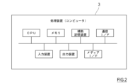
- FIG. 2 is a block diagram showing a schematic configuration of a processing device provided in the tooth contact inspection device.
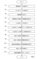
- FIG. 3 is a flow chart of the processing performed by the processing device provided in the tooth contact inspection device.
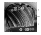
- FIG. 4 is an example of a gear image.
- FIG. 5 is an example of the AR synthesis data.
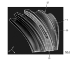
- FIG. 6 is an example of AR synthesis data showing the tooth contact area.
- FIG. 1 is a functional block diagram of a gear tooth contact inspection device 1 according to one embodiment of the present disclosure.
- the tooth contact inspection device 1 shown in FIG. 1 includes an imaging device 2 and a processing device 3.
- the tooth contact inspection device 1 is a device that inspects the tooth contact of a pair of meshing gears.
- the imaging device 2 includes a camera 21 that images the gear 5 to be inspected out of the gear pair, and an illumination device 22 that illuminates the field of view of the camera 21 .
- the camera 21 is attached, for example, via a jig to a casing that houses the gear 5.
- the camera 21 may be detachable from the casing so that it can be installed at the appropriate time, such as during assembly or maintenance.
- the field of view of the camera 21 includes at least one tooth surface of the gear 5 to be inspected.
- the camera 21 is, for example, a 2D camera equipped with a CCD imaging element, and the camera 21 takes images and generates two-dimensional captured image data.
- the camera 21 may also be a 3D camera. In this case, the camera 21 is, for example, a stereo 3D camera, and the camera 21 takes images and generates three-dimensional captured image data.
- the lighting device 22 projects direct or indirect light toward the field of view of the camera 21.
- the lighting device 22 is equipped with a light source suitable for the imaging method of the camera 21.
- the lighting device 22 is attached to the casing via a jig, for example, in the same manner as the camera 21.
- the lighting device 22 may be disposed integrally with the camera 21, or may be disposed separately from the camera 21.
- the processing device 3 acquires photographed image data from the imaging device 2 and processes the photographed image data to analyze the tooth contact and generate a tooth contact inspection result based on the analysis result.
- the processing device 3 has functional parts, an image processing part 31 that analyzes the tooth contact state by image processing, and an inspection part 32 that evaluates the tooth contact state based on the analysis result. The specific processing contents of each functional part will be described in detail later.
- FIG. 2 is a block diagram showing the schematic configuration of the processing device 3 provided in the tooth contact inspection device 1.
- the processing device 3 can be realized by a computer equipped with a CPU (Central Processing Unit), memory, an auxiliary storage device such as a HDD (Hard Disk Drive), a communication I/F for connecting to a communication network or the imaging device 2 via a wired or wireless connection, input devices such as a mouse, keyboard, touch sensor or touch panel, an output device such as a display, and a media I/F for reading and writing information from and to a portable storage medium.
- a CPU Central Processing Unit
- memory a auxiliary storage device
- HDD Hard Disk Drive
- communication I/F for connecting to a communication network or the imaging device 2 via a wired or wireless connection
- input devices such as a mouse, keyboard, touch sensor or touch panel
- an output device such as a display
- a media I/F for reading and writing information from and to a portable storage medium.
- Each function of the processing device 3 can be realized by loading a specific program stored in an auxiliary storage device into memory and executing it with the CPU.
- Communication between the processing device 3 and the imaging device 2 can be realized, for example, by the CPU using a communication I/F.
- the above-mentioned specific program may be downloaded to the processing device 3 from a network via the communication I/F, or may be loaded to the processing device 3 from a storage medium connected to the media I/F.
- the processing device 3 may be located near the imaging device 2 or remotely.
- An example of a case in which the processing device 3 is located remotely from the imaging device 2 is where the imaging device 2 is located at an assembly site for a product incorporating the gear 5, and the processing device 3 is built on a web server or located in an office.
- the auxiliary storage device of the processing device 3 contains an image database 35, a 3D reference database 36, and a gear database 37.
- the image database 35 stores an image file 351.
- the image file 351 is image data obtained by imaging with the imaging device 2 linked to a gear ID.
- the gear ID is information unique to the gear 5, and the gear 5 can be identified using the gear ID.
- the captured image data may include imaging information such as the date and time of capture and the number of colors in addition to the digital data of the captured image.
- the CPU of the processing device 3 links the captured image data obtained from the imaging device 2 to the gear ID and stores it in the image database 35. Furthermore, the CPU of the processing device 3 can read out the image file 351 containing the captured image data of the gear 5 identified by the gear ID from the image database 35 based on the gear ID.
- the 3D reference database 36 stores a 3D model file 361.
- the 3D model file 361 is 3D model data that is model data of the three-dimensional shape of the tooth surface of the gear 5, and is linked to the gear ID.
- the CPU of the processing device 3 can read out the 3D model file 361 containing the 3D model data of the gear 5 identified by the gear ID from the 3D reference database 36 based on the gear ID.
- the 3D model data of the gear 5 may be data obtained by measuring the actual gear 5 with a three-dimensional measuring machine, or computer-aided design data of the gear 5.
- the 3D model data may also include three-dimensional shape data of the tooth surfaces of all teeth of the gear 5, or may include three-dimensional shape data of the tooth surfaces of one or more teeth arranged in the circumferential direction.
- point cloud data having position information (x, y, z) of the tooth surface of the gear 5 in a specified three-dimensional spatial coordinate system is obtained, and the point cloud data is polygonized to generate STL data of the tooth surface shape.
- the STL data may be converted into 3DXML data.
- This STL data or 3DXML data of the tooth flank shape can be used as the 3D model data.
- the data format of the 3D model data may be other three-dimensional data formats.
- the 3D reference database 36 further stores a tooth surface information file 362.
- the tooth surface information file 362 holds coordinate position information of the ridgeline of the tooth surface of the gear 5 when the 3D model is mapped and information on the angle of view, linked to the gear ID.
- the ridgeline of the tooth surface is a line connecting the boundary between the tooth tip (or at least one of the tooth base, large diameter end, and small diameter end) and the tooth surface.
- the coordinate position information of the ridgeline of the tooth surface is generated and updated by the image processing unit 31.
- the angle of view is information of three-dimensional spatial coordinates when a virtual gear described later is displayed on the screen, and the angle of view information is generated and updated by the processing of the image processing unit 31.
- the tooth surface information file 362 is used in combination with the 3D model file 361.
- Gear database 37 stores gear files 371.
- Gear files 371 hold product information for gears 5, such as product number information, manufacturer information, structural information such as dimensions and number of teeth, and design drawing information.
- One gear file 371 is associated with a gear ID.
- the gear database 37 further stores a criterion file 372.
- the criterion file 372 holds information related to the criterion for tooth contact inspection.
- the data in the criterion file 372 may be combined with the gear file 371.
- the criterion for tooth contact inspection differs for each gear 5 product, and may also differ for each individual gear 5.
- one criterion file 372 is associated with each gear 5 product.
- one criterion file 372 is associated with each gear ID.
- Fig. 3 is a flow chart of processing by the processing device 3 included in the tooth contact inspection device 1.
- paint is applied to the tooth surface of the gear 5 that is not the subject of inspection in the gear pair, the gear pair is rotated, and the paint is transferred to the tooth surface of the gear 5 that is the subject of inspection, thereby visualizing the tooth contact marks of the gear 5.
- paint may also be applied to the tooth surface of the gear 5 that is the subject of inspection in the gear pair, the gear pair is rotated, and the tooth contact marks of the gear 5 are visualized by the paint remaining on the tooth surface of the gear 5 that is the subject of inspection.
- the tooth surface of the object of observation having tooth contact marks visualized by paint in this way is referred to as the "target tooth surface 50".
- the imaging device 2 captures an image of a part or the whole of the gear 5 including the target tooth surface 50, and generates captured image data. This captured image data is output from the imaging device 2 to the processing device 3 and stored in the image database 35 as an image file 351 associated with the gear ID.
- the image processing unit 31 of the processing device 3 reads out the corresponding image file 351 from the image database 35 based on the gear ID of the gear 5 to be inspected, and acquires the photographed image data of the gear 5 (step S1).
- the image processing unit 31 also reads out the corresponding 3D model file 361 from the 3D reference database 36 based on the gear ID of the gear 5 to be inspected, and acquires the 3D model data (step S2). If a tooth surface information file 362 exists, the image processing unit 31 reads out the corresponding tooth surface information file 362 from the 3D reference database 36 based on the gear ID of the gear 5 to be inspected, and acquires the coordinate position information of the ridge line and the angle of view information.
- the image processing unit 31 generates a gear image including the target tooth surface 50 from the captured image data (step S3), and displays the gear image on a display, which is an output device.
- the image processing unit 31 may generate the gear image by performing filter processing such as image size adjustment and smoothing on the acquired captured image data.
- filter processing such as image size adjustment and smoothing
- the gear image i.e., an image of a portion of the gear 5 including the target tooth surface 50, is displayed on the display screen. Tooth contact marks 51 are visualized on the target tooth surface 50 by the use of paint.
- the operator sets a predetermined feature point on the gear image displayed on the display screen by inputting.
- the position of the feature point is indicated by a drop-shaped tip containing a number.
- the operator can set the feature point on the gear image, for example, by moving a mouse pointer operated by a mouse, which is an input device, or by touching or pressing a touch panel.
- the feature points preferably include both ends of the tooth tip of the target tooth surface 50 in the tooth trace direction, and both ends of the tooth base of the target tooth surface 50 in the tooth trace direction.
- the feature points further preferably include both ends of the tooth tip of the corresponding tooth surfaces (i.e., tooth surfaces facing the same rotation direction) on both sides of the target tooth surface 50 in the tooth trace direction, and both ends of the tooth base of the corresponding tooth surfaces on both sides of the target tooth surface 50 in the tooth trace direction.
- the feature points are designated in advance, and the operator may be configured to designate the designated feature points on the gear image.
- the image processing unit 31 acquires the position information of the characteristic points on the gear image input as described above (step S4).
- the characteristic points are set by input by the operator, but the image processing unit 31 may automatically extract the characteristic points by image analysis.
- the image processing unit 31 performs a process of extracting the contour of the tooth surface based on, for example, the difference in shading in the gear image, and setting the specified characteristic points on the contour of the tooth surface.
- the image processing unit 31 uses AR (Augmented Reality) technology to generate AR synthetic data by superimposing the gear image on the virtual gear 52 in a three-dimensional space coordinate system (step S5), and displays and outputs the AR synthetic data on the display screen.
- the AR synthetic data i.e., the AR synthetic image
- the virtual gear 52 is a three-dimensional gear shape model generated from 3D model data.
- the virtual gear 52 may be a part of the three-dimensional gear shape model including about one to five teeth.
- the virtual gear 52 is assigned feature points corresponding to the feature points of the gear image.
- the feature points may be specified in advance for the virtual gear 52, or the points corresponding to the feature points of the gear image may be set after the generation of the AR synthetic data.
- the image processing unit 31 maps the gear image onto the virtual gear 52 so that the corresponding feature points of the real-world gear image and the virtual gear 52 overlap.
- the image processing unit 31 stores coordinate position information of the ridge line of the tooth surface of the virtual gear 52 on which the real-world gear image is superimposed in the tooth surface information file 362 of the 3D reference database 36.
- the image processing unit 31 also stores field of view information of the virtual gear 52 on which the real-world gear image is superimposed in the tooth surface information file 362 of the 3D reference database 36. Note that the AR processing method for superimposing the real-world gear image displayed on the screen on the virtual gear 52 is not limited to the above.
- the virtual gear 52 in the AR composite image is displayed, for example, as a see-through view or a contour view so that the real-world gear image (particularly the target tooth surface 50 and the tooth contact mark 51 on the target tooth surface 50) can be visually recognized.
- the virtual gear 52 may be able to be switched between display and non-display in the AR composite image.
- the image processing unit 31 can display an inspection grid 53 for tooth contact inspection on the tooth surface of the virtual gear 52 (step S6). Information for displaying the inspection grid 53 on the display screen is included in the 3D model data.
- the inspection grid 53 is displayed superimposed on the tooth surface of the virtual gear 52.
- the inspection grid 53 is, for example, composed of a frame line surrounding the tooth surface of the virtual gear 52 superimposed on the target tooth surface 50, and vertical and horizontal ruled lines arranged within the frame line.
- the ruled lines include a center line and auxiliary lines, and the interval between the ruled lines may be set according to the judgment criteria.
- the inspection grid 53 serves as a guide for the operator as to the position and size when visually recognizing the paint adhesion area on the tooth surface.
- the operator inputs and specifies the tooth contact area 55 in the AR synthetic data displayed on the display screen.
- the tooth contact area 55 is an area in the AR synthetic data in a three-dimensional coordinate system that corresponds to or overlaps with the tooth contact mark 51 of the real-world gear image. As illustrated in FIG. 6, the tooth contact area 55 is specified, for example, by specifying the contour of the tooth contact mark 51 on the AR synthetic data.
- the operator inputs the positions of multiple points on the contour of the tooth contact mark 51 displayed on the gear image, for example, by moving the mouse pointer operated by the mouse, which is an input device, or by contacting or pressing the touch panel.
- the image processing unit 31 acquires the position information of the multiple points on the contour of the tooth contact mark 51 in the three-dimensional coordinate system, identifies the contour of the tooth contact area 55 by connecting the multiple points with lines, and identifies the inside of the contour of the identified tooth contact area 55 as the tooth contact area 55 (step S7), and obtains and stores the position information of the three-dimensional coordinate system of the tooth contact area 55 (step S8).
- the tooth contact area 55 is specified by input from the operator, but the tooth contact area 55 may also be specified automatically by the image processing unit 31.
- the image processing unit 31 extracts the outline of the tooth contact mark 51 on the gear image by, for example, image analysis, and specifies the inside of the extracted outline as the tooth contact area 55.
- the inspection unit 32 of the processing device 3 acquires position information of the tooth contact area 55 in the three-dimensional spatial coordinate system (step S9).
- the inspection unit 32 evaluates the tooth contact state using the inspection grid 53 and the position information of the tooth contact area 55 in the three-dimensional spatial coordinate system.
- the inspection unit 32 reads out the gear file 371 and the judgment criteria file 372 corresponding to the gear 5 to be inspected from the gear database 37, and acquires this information (step S10). Then, the inspection unit 32 uses a given arithmetic expression to calculate a value for evaluating the tooth contact state for each item of the tooth contact inspection, compares the value with the judgment criteria to automatically evaluate the tooth contact state (step S11), and stores the evaluation.
- the evaluation of the tooth contact state may be expressed as good or bad or in points. For example, the inspection unit 32 calculates the size and area of the tooth contact region 55 in the tooth trace direction and tooth depth direction based on the position information of the inspection grid 53 and the tooth contact region 55, and compares the calculated size and area with the judgment criteria to evaluate the tooth contact state.
- the inspection unit 32 calculates the position of the center of the tooth contact region 55 in the tooth trace direction relative to the tooth surface based on the position information of the inspection grid 53 and the tooth contact region 55, and compares the calculated position with the judgment criteria to evaluate the tooth contact state.
- the items of the tooth contact inspection are determined by the requirements of the product to which the gear is applied, and are not limited to the above.
- the inspection unit 32 may make a comprehensive pass/fail judgment of the inspection based on the evaluation of a given tooth contact inspection item.
- the judgment criteria are combined in the gear file 371, the tooth contact area 55 and the position information of the tooth contact area 55 of the judgment criteria contained in the gear file 371 (or the shape information of the tooth contact area 55) may be directly superimposed to make the judgment.
- the inspection unit 32 generates and outputs inspection result information using the generated gear image, AR composite data, gear information, etc. as a result of the evaluation of the tooth contact state (step S12).
- the inspection result information includes, for example, gear information, gear image, AR composite data, evaluation values and judgment criteria for each item of the tooth contact inspection, and pass/fail judgment.
- the inspection unit 32 can display and output the generated inspection result information on a display as an output device, or print it out from a printer to create an inspection report.
- the tooth contact inspection device 1 for a gear 5 is A processing device 3 is provided.
- the processing device 3 includes: Acquire photographed image data of a gear 5 including a target tooth surface 50 having a tooth contact mark 51 visualized by paint; A gear image including the target tooth surface 50 is generated from the captured image data.
- the gear tooth contact inspection device 1 for the gear 5 according to the second item of the present disclosure is the gear tooth contact inspection device 1 for the gear 5 according to the first item, further comprising an imaging device 2 for generating captured image data.
- the AR synthetic data is obtained by superimposing a real-world gear image on a virtual gear 52, and the visual information of the virtual gear 52 clarifies the contour of the tooth surface, which is unclear in the real-world gear image, and the position and dimensions of the tooth contact mark 51 on the tooth surface.
- the visual information of the virtual gear 52 clarifies the contour of the tooth surface, which is unclear in the real-world gear image, and the position and dimensions of the tooth contact mark 51 on the tooth surface.
- part of the tooth surface is not displayed in the gear image or if the gear tooth surface is twisted, it is difficult to accurately capture the dimensions and shape of the tooth contact mark 51 on the tooth surface using only the gear image obtained by shooting.
- the gear image on the virtual gear 52 as AR content and using the shape information of the virtual gear 52 to identify the shape of the tooth surface of the gear in the real world, the dimensions and shape of the tooth contact mark 51 can be more accurately identified. Furthermore, since the position of the tooth contact mark 51 can be represented and the dimensions can be measured using the three-dimensional spatial coordinate system of the virtual gear 52, the accuracy of measuring the position and dimensions of the tooth contact mark 51 relative to the target tooth surface 50 can be improved.
- the tooth contact inspection device 1 for a gear 5 according to the third item of the present disclosure is the tooth contact inspection device 1 for a gear 5 according to the first or second item, in which the processing device 3 is configured to display, in the AR synthesis data, a frame line surrounding the tooth surface of the virtual gear 52 that overlaps with the target tooth surface 50, and an inspection grid 53 having ruled lines arranged within the frame line.
- the ruled lines may include a center line and auxiliary lines.
- the operator can easily visually confirm the dimensions and position of the tooth contact mark 51 on the tooth surface from the inspection grid 53 and tooth contact mark 51 shown in the AR composite data output as an image.
- the tooth contact inspection device 1 for a gear 5 according to the fourth item of the present disclosure is a tooth contact inspection device 1 for a gear 5 according to any one of the first to third items, in which the processing device 3 is configured to set the area in the AR synthetic data that overlaps with the tooth contact mark 51 as the tooth contact area 55, obtain position information of the tooth contact area 55 in a three-dimensional spatial coordinate system, and evaluate the tooth contact state based on the position information of the tooth contact area 55 in the three-dimensional spatial coordinate system.
- the processing device 3 can inspect the tooth contact state based on the position information of the tooth contact area 55 without human judgment. This allows for stable inspection quality.
- the tooth contact inspection device 1 for a gear 5 according to the fifth item of the present disclosure is the tooth contact inspection device 1 for a gear 5 according to the fourth item, in which the processing device 3 is configured to acquire position information of a plurality of points on the contour of the tooth contact mark 51 in the AR synthetic data, connect the plurality of points with lines to identify the contour of the tooth contact area 55, and obtain the position information of the tooth contact area 55 from the identified contour of the tooth contact area 55.
- the processing device 3 can obtain the position information of multiple points on the outline of the tooth contact mark 51 input by the worker while visually checking the AR composite data output as an image, simplifying the processing.
- the tooth contact inspection device 1 for a gear 5 according to the sixth item of the present disclosure is a tooth contact inspection device 1 for a gear 5 according to any one of the first to fifth items, in which the processing device 3 is configured to obtain criteria information for the tooth contact state and automatically determine the tooth contact state by comparing the tooth contact area 55 with the criteria information.
- the tooth contact inspection device 1 configured as above can automatically determine the quality or evaluation of the tooth contact condition of the gear 5.
- the gear tooth contact inspection device 1 for gears 5 according to the seventh item of the present disclosure is a gear tooth contact inspection device 1 for gears 5 according to any one of the first to sixth items, in which the processing device 3 is configured to output inspection result information including the evaluation result of the tooth contact state and the AR composite data.
- tooth contact inspection device 1 configured as above, even the creation of inspection reports can be automated. Furthermore, if inspection result information is accumulated, it can be used to improve reproducibility and traceability.
- the tooth contact inspection method of the gear 5 is a tooth contact inspection method of the gear 5 performed by a computer (i.e., the processing device 3), comprising: Acquiring photographed image data of a gear 5 including a target tooth surface 50 having a tooth contact mark 51 visualized by paint; Generating a gear image including the target tooth surface 50 from the captured image data; Obtaining 3D model data of the gear 5; Generating AR composite data by superimposing a virtual gear 52 in a three-dimensional spatial coordinate system generated from the 3D model data on a gear image; and and evaluating the tooth contact condition based on the tooth contact marks 51 and the corresponding tooth contact areas 55 of the AR synthesis data.
- the AR synthetic data is obtained by superimposing a real-world gear image on the virtual gear 52, and the visual information of the virtual gear 52 clarifies the contour of the tooth surface, which is unclear in the real-world gear image, and the position and dimensions of the tooth contact mark 51 on the tooth surface.
- the visual information of the virtual gear 52 clarifies the contour of the tooth surface, which is unclear in the real-world gear image, and the position and dimensions of the tooth contact mark 51 on the tooth surface.
- the dimensions and shape of the tooth contact mark 51 can be more accurately identified. Furthermore, since the position of the tooth contact mark 51 can be represented and the dimensions can be measured using the three-dimensional spatial coordinate system of the virtual gear 52, the accuracy of measuring the position and dimensions of the tooth contact mark 51 relative to the target tooth surface 50 can be improved.
- the functions performed by the processing device 3 described herein may be implemented in a circuitry or processing circuit, including general purpose processors, application specific processors, integrated circuits, ASICs (Application Specific Integrated Circuits), CPUs (Central Processing Units), conventional circuits, and/or combinations thereof, programmed to perform the described functions.
- Processors include transistors and other circuits and are considered to be circuitry or processing circuitry.
- a processor may be a programmed processor that executes a program stored in a memory.
- a circuitry, unit, or means is hardware that is programmed to perform or executes the described functions.
- the hardware may be any hardware disclosed in this specification or any hardware that is programmed to perform or is known to perform the described functions. If the hardware is a processor, which is considered to be a type of circuitry, the circuitry, means, or unit is a combination of hardware and software used to configure the hardware and/or processor.
- Tooth contact inspection device 2 Imaging device 3: Processing device 5: Gear 50: Target tooth surface 51: Tooth contact mark 52: Virtual gear 53: Inspection grid 55: Tooth contact area
Landscapes
- Engineering & Computer Science (AREA)
- Multimedia (AREA)
- Signal Processing (AREA)
- Physics & Mathematics (AREA)
- General Physics & Mathematics (AREA)
- Theoretical Computer Science (AREA)
- Computer Graphics (AREA)
- Computer Hardware Design (AREA)
- General Engineering & Computer Science (AREA)
- Software Systems (AREA)
- Computer Vision & Pattern Recognition (AREA)
- Length Measuring Devices By Optical Means (AREA)
Abstract
歯車の歯当たり検査は、塗料により視覚化された歯当たり痕を有する対象歯面を含む歯車の撮影画像データを取得し、撮影画像データから対象歯面を含む歯車画像を生成し、歯車の3Dモデルデータを取得し、3Dモデルデータから生成された三次元空間座標系のバーチャル歯車に歯車画像を重ね合わせたAR合成データを生成し、AR合成データの歯当たり痕と対応する歯当たり領域に基づいて歯当たり状態を評価するように構成された処理装置を備える。
Description
本開示は、歯車の歯当たり検査に使用される装置及びそれを用いた歯当たり検査方法に関する。
歯車の歯当たりは歯車の騒音や伝達動力及び伝達効率に影響を与える要素の一つであり、歯車の組立や保守の際に歯当たり検査が行われる。歯当たり検査では、作業者が、歯面に塗料を塗布し、歯車を噛み合わせて、噛み合いによって擦り取られた塗料又は擦り取り後の残留塗料をテープに転写し、テープに転写された塗料を目視で観察することにより歯当たりの重心や面積等の評価を行っている。しかし、このような従来の検査方法は、塗料を転写したテープの汚れや不明瞭な歯面輪郭により判定精度が低下すること、作業者の技量に左右されることなどの課題がある。そこで、作業者の目視官能検査に頼ることのない、定量的な歯車の歯当たり検査を実現する方法が提案されている。
例えば、特許文献1に記載の歯車の歯当たり検査方法は、検査対象の歯車の被検査面又はこの歯車と噛み合う歯車の歯合面に塗料を塗布し、歯車対の回転に伴って剥離が発生した被検査面上の残留塗料をテープに転写し、この塗料が転写されたテープをカメラで撮影して得られた画像データを、コンピュータを用いて画像処理することによって被検査面での歯当たり状況を検査するものである。
しかし、上記特許文献1の方法では、被検査面の領域をどのように特定するかが明らかとされておらず、歯面上の歯当たりの寸法及び位置やそれらに含まれる誤差等の情報は得られない。
本開示は以上の事情に鑑みてなされたものであり、その目的は、歯車の歯当たり検査において、歯面上の歯当たりの寸法や位置の測定精度を向上することにある。
上記課題を解決するために、本開示の一態様に係る歯当たり検査装置は、
処理装置を備え、
前記処理装置は、
塗料により視覚化された歯当たり痕を有する対象歯面を含む歯車の撮影画像データを取得し、
前記撮影画像データから前記対象歯面を含む歯車画像を生成し、
前記歯車の3Dモデルデータを取得し、
前記3Dモデルデータから生成された三次元空間座標系のバーチャル歯車に前記歯車画像を重ね合わせたAR合成データを生成し、
前記AR合成データの前記歯当たり痕と対応する歯当たり領域に基づいて歯当たり状態を評価するように構成されているものである。
処理装置を備え、
前記処理装置は、
塗料により視覚化された歯当たり痕を有する対象歯面を含む歯車の撮影画像データを取得し、
前記撮影画像データから前記対象歯面を含む歯車画像を生成し、
前記歯車の3Dモデルデータを取得し、
前記3Dモデルデータから生成された三次元空間座標系のバーチャル歯車に前記歯車画像を重ね合わせたAR合成データを生成し、
前記AR合成データの前記歯当たり痕と対応する歯当たり領域に基づいて歯当たり状態を評価するように構成されているものである。
また、本開示の一態様に係る歯当たり検査方法は、コンピュータにより行われる歯車の歯当たり検査方法であって、
塗料により視覚化された歯当たり痕を有する対象歯面を含む歯車の撮影画像データを取得すること、
前記歯車の3Dモデルデータを取得すること、
前記撮影画像データから前記対象歯面を含む歯車画像を生成すること、
前記3Dモデルデータから生成された三次元空間座標系のバーチャル歯車に前記歯車画像を重ね合わせたAR合成データを生成すること、及び、
前記AR合成データの前記歯当たり痕と対応する歯当たり領域に基づいて歯当たり状態を評価すること、を含むものである。
塗料により視覚化された歯当たり痕を有する対象歯面を含む歯車の撮影画像データを取得すること、
前記歯車の3Dモデルデータを取得すること、
前記撮影画像データから前記対象歯面を含む歯車画像を生成すること、
前記3Dモデルデータから生成された三次元空間座標系のバーチャル歯車に前記歯車画像を重ね合わせたAR合成データを生成すること、及び、
前記AR合成データの前記歯当たり痕と対応する歯当たり領域に基づいて歯当たり状態を評価すること、を含むものである。
本開示によれば、歯車の歯当たり検査において、歯面上の歯当たりの寸法や位置の測定精度を向上できる。
次に、図面を参照して本開示の実施の形態を説明する。図1は本開示の一実施形態に係る歯車の歯当たり検査装置1の機能ブロック図である。図1に示す歯当たり検査装置1は、撮像装置2と、処理装置3とを備える。歯当たり検査装置1は、噛み合う歯車対の歯当たりを検査する装置である。
《撮像装置2》
撮像装置2は、歯車対のうち検査対象の歯車5を撮像するカメラ21と、カメラ21の視野を照らす照明装置22とを含む。
撮像装置2は、歯車対のうち検査対象の歯車5を撮像するカメラ21と、カメラ21の視野を照らす照明装置22とを含む。
カメラ21は、例えば、歯車5を収容したケーシングに治具を介して取り付けられている。カメラ21は、組立時や保守時などの適時に設置できるように、ケーシングに対し着脱可能であってよい。カメラ21の視野には、検査対象の歯車5の少なくとも1つの歯面が含まれる。カメラ21は、例えば、CCD撮像素子を搭載した2Dカメラであり、カメラ21は画像の撮影と二次元の撮影画像データの生成とを行う。但し、カメラ21は、3Dカメラであってもよい。この場合は、カメラ21は、例えば、ステレオ方式の3Dカメラであり、カメラ21は画像の撮影と三次元の撮影画像データの生成とを行う。
照明装置22は、カメラ21の視野に向けて直接光又は間接光を投光する。照明装置22は、カメラ21の撮像方式に適した光源を搭載している。照明装置22は、例えば、カメラ21と同様に治具を介してケーシングに取り付けられている。照明装置22は、カメラ21と一体的に配置されていてもよいし、カメラ21から離れて配置されていてもよい。
《処理装置3》
処理装置3は、撮像装置2から撮影画像データを取得し、撮影画像データを処理することによって、歯当たりの解析と、解析結果に基づく歯当たり検査結果の生成とを行う。処理装置3は、画像処理により歯当たり状態の解析を行う画像処理部31と、解析結果に基づいて歯当たり状態の評価を行う検査部32との各機能部を有する。各機能部の具体的な処理の内容については後ほど詳述する。
処理装置3は、撮像装置2から撮影画像データを取得し、撮影画像データを処理することによって、歯当たりの解析と、解析結果に基づく歯当たり検査結果の生成とを行う。処理装置3は、画像処理により歯当たり状態の解析を行う画像処理部31と、解析結果に基づいて歯当たり状態の評価を行う検査部32との各機能部を有する。各機能部の具体的な処理の内容については後ほど詳述する。
図2は、歯当たり検査装置1が具備する処理装置3の概略構成を示すブロック図である。図2に示すように、処理装置3は、CPU(Central Processing Unit)と、メモリと、HDD(Hard Disk Drive)等の補助記憶装置と、有線又は無線により通信網や撮像装置2に接続するための通信I/Fと、マウス、キーボード、タッチセンサーやタッチパネルなどの入力装置と、ディスプレイなどの出力装置と、持ち運び可能な記憶媒体に対する情報の読み書きを行うメディアI/Fと、を備えるコンピュータで実現できる。
処理装置3の各機能は、補助記憶装置に記憶されている所定のプログラムをメモリにロードしてCPUで実行することで実現可能である。処理装置3と撮像装置2の通信は、例えば、CPUが通信I/Fを利用することで実現可能である。なお、上記の所定のプログラムは、例えば、通信I/Fを介してネットワーク上から処理装置3へダウンロードされてもよいし、メディアI/Fに接続された記憶媒体から処理装置3へロードされてもよい。
処理装置3は、撮像装置2の近くに配置されていてもよいし、遠隔に配置されていてもよい。処理装置3が撮像装置2の遠隔に配置された例として、撮像装置2は歯車5を組み込んだ製品の組立現場に配置され、処理装置3はウエブサーバ上に構築されたり事務所に配置される態様が挙げられる。
図1に戻って、処理装置3の補助記憶装置には、画像データベース35、3D基準データベース36、及び、歯車データベース37が構築されている。
画像データベース35には、画像ファイル351が格納されている。画像ファイル351は、撮像装置2での撮像により得られた撮影画像データが歯車IDに紐づけられたものである。歯車IDは、歯車5に固有の情報であり、歯車IDを用いて歯車5を識別できる。撮影画像データには、撮像画像のデジタルデータに加えて、撮影日時や色数などの撮影情報が含まれていてよい。処理装置3のCPUは、撮像装置2から取得した撮影画像データを歯車IDに紐づけて画像データベース35に保存する。また、処理装置3のCPUは、歯車IDに基づいて、当該歯車IDで識別される歯車5の撮影画像データを含む画像ファイル351を画像データベース35から読み出すことができる。
3D基準データベース36には、3Dモデルファイル361が格納されている。3Dモデルファイル361は、歯車5の歯面の三次元形状のモデルデータである3Dモデルデータが歯車IDに紐づけられたものである。処理装置3のCPUは、歯車IDに基づいて、当該歯車IDで識別される歯車5の3Dモデルデータを含む3Dモデルファイル361を3D基準データベース36から読み出すことができる。歯車5の3Dモデルデータは、実際の歯車5を三次元測定機で測定して得たデータ、或いは、歯車5のコンピュータ支援設計データであってよい。また、3Dモデルデータは、歯車5の全ての歯の歯面の三次元形状データを含んでいてもよいし、周方向に並ぶ1歯又は複数の歯の歯面の三次元形状データを含んでいてもよい。例えば、非接触三次元測定機で歯車5を測定すると、所定の三次元空間座標系における歯車5の歯面の位置情報(x,y,z)を持った点群データが得られ、点群データをポリゴン化して歯面形状のSTLデータが生成される。STLデータは、3DXMLデータに変換されてもよい。この歯面形状のSTLデータ又は3DXMLデータを、3Dモデルデータとして用いることができる。なお、3Dモデルデータのデータフォーマットはその他の三次元データフォーマットであっても良い。
3D基準データベース36には、更に、歯面情報ファイル362が格納されている。歯面情報ファイル362は、3Dモデルをマッピングしたときの歯車5の歯面の稜線の座標位置情報と画角情報とを歯車IDに紐づけて保持するものである。歯面の稜線は歯先(又は、歯元、大径端、及び小径端の少なくとも1つ)と歯面との境界に沿って繋いだ線である。歯面の稜線の座標位置情報は画像処理部31により生成及び更新される。画角は後述するバーチャル歯車を画面に表示するときの三次元空間座標の情報であり、画角情報は画像処理部31の処理によって生成及び更新される。歯面情報ファイル362は、3Dモデルファイル361と組み合わせて用いられる。
歯車データベース37には、歯車ファイル371が格納されている。歯車ファイル371は、製品番号情報、製造メーカ情報、寸法や歯数などの構造情報、設計図面情報などの歯車5の製品情報を保持したものである。歯車IDに1つの歯車ファイル371が関連付けられている。
歯車データベース37には、更に、判定基準ファイル372が格納されている。判定基準ファイル372は、歯当たり検査の判定基準に係る情報を保持したものである。判定基準ファイル372のデータは、歯車ファイル371に複合されていてもよい。歯当たり検査の判定基準は、歯車5の製品ごとに異なり、また、個々の歯車5で異なることもある。歯車5の製品ごとに歯当たり検査の判定基準が異なる場合は、歯車5の製品につき1つの判定基準ファイル372が関連付けられている。また、個々の歯車5で歯当たり検査の判定基準が異なる場合は、歯車IDにつき1つの判定基準ファイル372が関連付けられている。
《歯当たり検査方法》
ここで上記構成の歯当たり検査装置1を用いた歯当たり検査方法について、図3を参照しながら説明する。図3は、歯当たり検査装置1が具備する処理装置3の処理の流れ図である。
ここで上記構成の歯当たり検査装置1を用いた歯当たり検査方法について、図3を参照しながら説明する。図3は、歯当たり検査装置1が具備する処理装置3の処理の流れ図である。
本実施形態では、歯車対のうち検査対象ではない歯車5の歯面に塗料を塗り、歯車対を回転させ、検査対象の歯車5の歯面に塗料を転写することにより、歯車5の歯当たり痕が視覚化されている。但し、歯車対のうち検査対象の歯車5の歯面に塗料を塗り、歯車対を回転させ、検査対象の歯車5の歯面に残った塗料によって、歯車5の歯当たり痕が視覚化されていてもよい。このように塗料によって視覚化された歯当たり痕を有する観察対象の歯面を、説明の便宜上「対象歯面50」と称する。
撮像装置2は、対象歯面50を含む歯車5の一部分又は全体を撮影し、撮影画像データを生成する。この撮影画像データは、撮像装置2から処理装置3へ出力され、歯車IDと関連づけられた画像ファイル351として画像データベース35に格納される。
処理装置3の画像処理部31は、検査対象の歯車5の歯車IDに基づいて、画像データベース35から該当する画像ファイル351を読み出し、歯車5の撮影画像データを取得する(ステップS1)。また、画像処理部31は、検査対象の歯車5の歯車IDに基づいて、3D基準データベース36から該当する3Dモデルファイル361を読み出して3Dモデルデータを取得する(ステップS2)。画像処理部31は、歯面情報ファイル362が存在する場合には、検査対象の歯車5の歯車IDに基づいて、3D基準データベース36から該当する歯面情報ファイル362を読み出して稜線の座標位置情報と画角情報を取得する。
画像処理部31は、撮影画像データから対象歯面50を含む歯車画像を生成し(ステップS3)、歯車画像を出力装置であるディスプレイに表示出力させる。ここで、画像処理部31は、取得した撮影画像データにイメージサイズの調整処理やスムージングなどのフィルタ処理を行うことにより、歯車画像を生成してよい。これにより、図4に例示されるように、ディスプレイ画面には歯車画像、即ち、対象歯面50を含む歯車5の一部分の画像が表示される。対象歯面50には、塗料によって歯当たり痕51が視覚化されている。
作業者は、ディスプレイ画面に表示された歯車画像上に、予め定められた特徴点を入力により設定する。図4では、数字を含むドロップ型の尖端で特徴点の位置が示されている。作業者は、例えば、入力装置であるマウスで操作されるマウスポインタの移動や、タッチパネルの接触又は押圧によって、歯車画像上に特徴点を設定できる。特徴点は、複数、好ましくは4つ以上である。特徴点は、好ましくは、対象歯面50の歯先の歯すじ方向両端の点、及び、対象歯面50の歯元の歯すじ方向両端の点を含む。特徴点は、更に好ましくは、対象歯面50の両隣の対応歯面(即ち、同じ回転方向を向いた歯面)の歯先の歯すじ方向両端の点、及び、対象歯面50の両隣の対応歯面の歯元の歯すじ方向両端の点を含む。特徴点は予め指定されており、作業者は指定された特徴点を歯車画像上で指定するように構成されていてもよい。
画像処理部31は、上記のように入力された歯車画像上の特徴点の位置情報を取得する(ステップS4)。なお、本実施形態では特徴点を作業者の入力により設定しているが、画像処理部31が画像解析により特徴的を自動的に抽出してもよい。この場合、画像処理部31は、例えば、歯車画像の陰影の差等に基づいて歯面の輪郭を抽出し、歯面の輪郭上に所定の特徴点を設定する処理を行う。
画像処理部31は、AR(Augmented Reality)技術を用いて、歯車画像を三次元空間座標系のバーチャル歯車52に重ね合わせたAR合成データを生成し(ステップS5)、ディスプレイ画面にAR合成データを表示出力する。図5に例示されるように、ディスプレイ画面に表示出力されたAR合成データ(即ち、AR合成画像)は、現実世界の歯車画像をバーチャル歯車52に重ね合わせたものである。バーチャル歯車52は、3Dモデルデータから生成された三次元の歯車形状モデルである。バーチャル歯車52は、三次元の歯車形状モデルのうち1乃至5枚程度の歯を含む一部分であってよい。バーチャル歯車52には、歯車画像の特徴点と対応する特徴点が付与される。特徴点はバーチャル歯車52に対して予め指定されても良いし、歯車画像の特徴点と対応する点がAR合成データの生成後に設定されてもよい。画像処理部31は、現実世界の歯車画像とバーチャル歯車52の対応する特徴点が重なるように、歯車画像をバーチャル歯車52にマッピングする。画像処理部31は、現実世界の歯車画像を重ね合わせたバーチャル歯車52の歯面の稜線の座標位置情報を3D基準データベース36の歯面情報ファイル362に記憶する。また、画像処理部31は、現実世界の歯車画像を重ね合わせたバーチャル歯車52の画角情報を3D基準データベース36の歯面情報ファイル362に記憶する。なお、画面に表示された現実世界の歯車画像をバーチャル歯車52に重ね合わせるためのAR処理方法は、上記に限定されない。
AR合成画像中のバーチャル歯車52は、現実世界の歯車画像(特に、対象歯面50、及び、対象歯面50上の歯当たり痕51)が視認できるように、例えば、透過図や輪郭線図として表示される。バーチャル歯車52は、AR合成画像への表示と非表示を切り替え可能であってもよい。画像処理部31は、バーチャル歯車52の歯面に歯当たり検査のための検査用グリッド53を表示させることができる(ステップS6)。ディスプレイ画面に検査用グリッド53を表示するための情報は、3Dモデルデータに含まれている。検査用グリッド53は、バーチャル歯車52の歯面に重ねて表示される。検査用グリッド53は、例えば、対象歯面50と重ね合わされたバーチャル歯車52の歯面を囲う枠線と、枠線内に配置された縦及び横の罫線からなる。罫線は中心線及び補助線を含み、罫線の間隔は判定基準に応じて設定されていてよい。検査用グリッド53は、作業者にとって、歯面上の塗料の付着領域を視認する際の位置や大きさの目安となる。
作業者は、ディスプレイ画面に表示出力されたAR合成データに、歯当たり領域55を入力により指定する。歯当たり領域55は、AR合成データにおいて現実世界の歯車画像の歯当たり痕51と対応又は重複する三次元空間座標系の領域である。図6に例示されるように、歯当たり領域55の指定は、例えば、AR合成データ上の歯当たり痕51の輪郭を指定することにより行われる。作業者は、例えば、入力装置であるマウスで操作されるマウスポインタの移動や、タッチパネルの接触又は押圧によって、歯車画像上に表れた歯当たり痕51の輪郭上の複数点の位置を入力する。画像処理部31は、歯当たり痕51の輪郭上の複数の点の三次元空間座標系の位置情報を取得し、複数の点を線で繋ぎ合わせることにより歯当たり領域55の輪郭を特定し、特定された歯当たり領域55の輪郭の内部を歯当たり領域55と特定し(ステップS7)、歯当たり領域55の三次元空間座標系の位置情報を求め(ステップS8)、記憶する。本実施形態では、歯当たり領域55の指定を作業者の入力により行っているが、歯当たり領域55の指定は画像処理部31により自動で行われてもよい。この場合、画像処理部31は、例えば、画像解析により歯車画像上の歯当たり痕51の輪郭を抽出し、抽出した輪郭の内部を歯当たり領域55と指定する。
処理装置3の検査部32は、三次元空間座標系の歯当たり領域55の位置情報を取得する(ステップS9)。検査部32は、三次元空間座標系の検査用グリッド53及び歯当たり領域55の位置情報を利用して、歯当たり状態を評価する。
検査部32は、歯車データベース37から、検査対象の歯車5と対応する歯車ファイル371及び判定基準ファイル372を読み出し、これらの情報を取得する(ステップS10)。そして、検査部32は、歯当たり検査の各項目について、所与の演算式を用いて歯当たり状態を評価するための数値を求め、当該数値と判定基準とを比較することにより歯当たり状態を自動的に評価し(ステップS11)、評価を記憶する。歯当たり状態の評価は、良否又はポイントで表されてよい。例えば、検査部32は、検査用グリッド53及び歯当たり領域55の位置情報に基づいて、歯当たり領域55の歯すじ方向及び歯たけ方向の寸法や面積を求め、求めた寸法や面積を判定基準と比較することにより、歯当たり状態を評価する。また、例えば、検査部32は、検査用グリッド53及び歯当たり領域55の位置情報に基づいて、歯面に対する歯当たり領域55の中心の歯すじ方向の位置を求め、求めた位置を判定基準と比較することにより、歯当たり状態を評価する。但し、歯当たり検査の項目は歯車の適用製品の要求により決定されるものであり、上記に限定されない。検査部32は、所与の歯当たり検査項目における評価に基づいて、検査の総合的な合否判定を行ってもよい。ここで、判定基準が歯車ファイル371に複合される場合には、歯当たり領域55と歯車ファイル371に含まれる判定基準の歯当たり領域55の位置情報(或いは、歯当たり領域55の形状情報)を直接重ね合わせて判定を行ってもよい。
検査部32は、歯当たり状態の評価の結果、生成した歯車画像及びAR合成データ、及び歯車情報等を用いて、検査成績情報を生成し、出力する(ステップS12)。検査成績情報には、例えば、歯車情報と、歯車画像と、AR合成データと、歯当たり検査の各項目の評価数値及び判定基準と、合否判定とが含まれる。検査部32は、生成した検査成績情報を、出力装置としてのディスプレイに表示出力したり、プリンタから印字出力して検査成績書を作成したりできる。
〔総括〕
本開示の第1の項目に係る歯車5の歯当たり検査装置1は、
処理装置3を備え、
処理装置3は、
塗料により視覚化された歯当たり痕51を有する対象歯面50を含む歯車5の撮影画像データを取得し、
撮影画像データから対象歯面50を含む歯車画像を生成し、
歯車5の3Dモデルデータを取得し、
3Dモデルデータから生成された三次元空間座標系のバーチャル歯車52に歯車画像を重ね合わせたAR合成データを生成し、
AR合成データの歯当たり痕51と対応する歯当たり領域55に基づいて歯当たり状態を評価するように構成されているものである。
本開示の第1の項目に係る歯車5の歯当たり検査装置1は、
処理装置3を備え、
処理装置3は、
塗料により視覚化された歯当たり痕51を有する対象歯面50を含む歯車5の撮影画像データを取得し、
撮影画像データから対象歯面50を含む歯車画像を生成し、
歯車5の3Dモデルデータを取得し、
3Dモデルデータから生成された三次元空間座標系のバーチャル歯車52に歯車画像を重ね合わせたAR合成データを生成し、
AR合成データの歯当たり痕51と対応する歯当たり領域55に基づいて歯当たり状態を評価するように構成されているものである。
本開示の第2の項目に係る歯車5の歯当たり検査装置1は、第1の項目に係る歯車5の歯当たり検査装置1において、撮影画像データを生成する撮像装置2を、更に備えるものである。
第1及び第2の項目に係る歯当たり検査装置1では、AR合成データは現実世界の歯車画像をバーチャル歯車52に重ね合わせたものであり、バーチャル歯車52の視覚情報によって現実世界の歯車画像では不明瞭な歯面の輪郭や歯面上の歯当たり痕51の位置や寸法が明確となる。また、歯車画像に歯面の一部が表示されていない場合や歯車の歯面が捻じれている場合には、撮影により得られた歯車画像のみでは歯面上の歯当たり痕51の寸法や形状を正確に捉えることが難しいが、歯車画像をARコンテンツとしてのバーチャル歯車52に重ね合わせて、現実世界の歯車の歯面の形状の特定にバーチャル歯車52の形状情報を利用することによって、歯当たり痕51の寸法や形状をより正確に特定できる。更に、バーチャル歯車52の三次元空間座標系を用いて歯当たり痕51の位置を表したり寸法を測定したりできるので、対象歯面50に対する歯当たり痕51の位置や寸法の測定の制度を向上できる。
本開示の第3の項目に係る歯車5の歯当たり検査装置1は、第1又は2の項目に係る歯車5の歯当たり検査装置1において、処理装置3は、AR合成データに、対象歯面50と重なったバーチャル歯車52の歯面を囲う枠線、及び、枠線内に配置された罫線を有する検査用グリッド53を表示するように構成されているものである。罫線は、中心線及び補助線を含んでいてよい。
上記構成の歯当たり検査装置1によれば、画像として出力されたAR合成データに示された検査用グリッド53と歯当たり痕51から、作業者は歯面における歯当たり痕51の寸法や位置を容易に視認できる。
本開示の第4の項目に係る歯車5の歯当たり検査装置1は、第1乃至3のいずれかの項目に係る歯車5の歯当たり検査装置1において、処理装置3は、AR合成データにおいて歯当たり痕51と重複する領域を歯当たり領域55とし、歯当たり領域55の三次元空間座標系の位置情報を取得し、歯当たり領域55の三次元空間座標系の位置情報に基づいて、歯当たり状態を評価するように構成されているものである。
上記構成の歯当たり検査装置1によれば、歯当たり領域55の位置情報に基づいて処理装置3が人の判断を介さずに歯当たり状態の検査を行うことができる。よって、安定した検査品質を提供できる。
本開示の第5の項目に係る歯車5の歯当たり検査装置1は、第4の項目に係る歯車5の歯当たり検査装置1において、処理装置3は、AR合成データにおいて歯当たり痕51の輪郭上の複数の点の位置情報を取得し、複数の点を線で繋ぎ合わせて歯当たり領域55の輪郭を特定し、及び、特定された歯当たり領域55の輪郭から歯当たり領域55の位置情報を求めるように構成されているものである。
歯面には歯当たり痕51以外にも塗料が付着していることがあり、塗料の付着状況を処理装置3で解析して歯当たり痕51を抽出することが煩雑となることがある。このような場合にも、上記構成の歯当たり検査装置1によれば、作業者が画像として出力されたAR合成データを視認しながら作業者が入力した歯当たり痕51の輪郭上の複数の点の位置情報を処理装置3が取得できるので、処理を単純化できる。
本開示の第6の項目に係る歯車5の歯当たり検査装置1は、第1乃至5のいずれかの項目に係る歯車5の歯当たり検査装置1において、処理装置3は、前記歯当たり状態の判定基準情報を取得し、歯当たり領域55を判定基準情報と照合して歯当たり状態を自動判定するように構成されているものである。
上記構成の歯当たり検査装置1によれば、歯車5の歯当たり状態の良否又は評価を自動的に判定することができる。
本開示の第7の項目に係る歯車5の歯当たり検査装置1は、第1乃至6のいずれかの項目に係る歯車5の歯当たり検査装置1において、処理装置3は、歯当たり状態の評価の結果及びAR合成データを含む検査成績情報を出力するように構成されているものである。
上記構成の歯当たり検査装置1によれば、検査成績書の作成までも自動化できる。また、検査成績情報を蓄積すれば、再現性の向上やトレーサビリティに利用できる。
本開示の第8の項目に係る歯車5の歯当たり検査方法は、コンピュータ(即ち、処理装置3)により行われる歯車5の歯当たり検査方法であって、
塗料により視覚化された歯当たり痕51を有する対象歯面50を含む歯車5の撮影画像データを取得すること、
撮影画像データから対象歯面50を含む歯車画像を生成すること、
歯車5の3Dモデルデータを取得すること、
3Dモデルデータから生成された三次元空間座標系のバーチャル歯車52を歯車画像に重ね合わせたAR合成データを生成すること、及び、
AR合成データの歯当たり痕51と対応する歯当たり領域55に基づいて歯当たり状態を評価すること、を含むものである。
塗料により視覚化された歯当たり痕51を有する対象歯面50を含む歯車5の撮影画像データを取得すること、
撮影画像データから対象歯面50を含む歯車画像を生成すること、
歯車5の3Dモデルデータを取得すること、
3Dモデルデータから生成された三次元空間座標系のバーチャル歯車52を歯車画像に重ね合わせたAR合成データを生成すること、及び、
AR合成データの歯当たり痕51と対応する歯当たり領域55に基づいて歯当たり状態を評価すること、を含むものである。
上記の歯車5の歯当たり検査方法によれば、AR合成データは現実世界の歯車画像をバーチャル歯車52に重ね合わせたものであり、バーチャル歯車52の視覚情報によって現実世界の歯車画像では不明瞭な歯面の輪郭や歯面上の歯当たり痕51の位置や寸法が明確となる。また、歯車画像に歯面の一部が表示されていない場合や歯車の歯面が捻じれている場合には、撮影により得られた歯車画像のみでは歯面上の歯当たり痕51の寸法や形状を正確に捉えることが難しいが、歯車画像にARコンテンツとしてのバーチャル歯車52を重ね合わせて、現実世界の歯車の歯面の形状の特定にバーチャル歯車52の形状情報を利用することによって、歯当たり痕51の寸法や形状をより正確に特定できる。更に、バーチャル歯車52の三次元空間座標系を用いて歯当たり痕51の位置を表したり寸法を測定したりできるので、対象歯面50に対する歯当たり痕51の位置や寸法の測定の制度を向上できる。
本明細書中に記載されている処理装置3により実現される機能は、当該記載された機能を実現するようにプログラムされた、汎用プロセッサ、特定用途プロセッサ、集積回路、ASICs(Application Specific Integrated Circuits)、CPU(Central Processing Unit)、従来型の回路、及び/又は それらの組合せを含む、circuitry又は processing circuitryにおいて実装されてもよい。プロセッサは、トランジスタやその他の回路を含み、circuitry又はprocessing circuitryとみなされる。プロセッサは、メモリに格納されたプログラムを実行する、programmed processorであってもよい。本明細書において、circuitry、ユニット、手段は、記載された機能を実現するようにプログラムされたハードウェア、又は実行するハードウェアである。当該ハードウェアは、本明細書に開示されているあらゆるハードウェア、又は、当該記載された機能を実現するようにプログラムされた、又は、実行するものとして知られているあらゆるハードウェアであってもよい。当該ハードウェアがcircuitryのタイプであるとみなされるプロセッサである場合、当該circuitry、手段、又はユニットは、ハードウェアと、当該ハードウェア及び又はプロセッサを構成する為に用いられるソフトウェアの組合せである。
以上の本開示の議論は、例示及び説明の目的で提示されたものであり、本開示を本明細書に開示される形態に限定することを意図するものではない。例えば、前述の詳細な説明では、本開示の様々な特徴は、本開示を合理化する目的で1つの実施形態に纏められているが、複数の特徴のうち幾つかが組み合わされてもよい。また、本開示に含まれる複数の特徴は、上記で論じたもの以外の代替の実施形態、構成、又は態様に組み合わされてもよい。
1 :歯当たり検査装置
2 :撮像装置
3 :処理装置
5 :歯車
50 :対象歯面
51 :歯当たり痕
52 :バーチャル歯車
53 :検査用グリッド
55 :歯当たり領域
2 :撮像装置
3 :処理装置
5 :歯車
50 :対象歯面
51 :歯当たり痕
52 :バーチャル歯車
53 :検査用グリッド
55 :歯当たり領域
Claims (8)
- 処理装置を備え、
前記処理装置は、
塗料により視覚化された歯当たり痕を有する対象歯面を含む歯車の撮影画像データを取得し、
前記撮影画像データから前記対象歯面を含む歯車画像を生成し、
前記歯車の3Dモデルデータを取得し、
前記3Dモデルデータから生成された三次元空間座標系のバーチャル歯車に前記歯車画像を重ね合わせたAR合成データを生成し、
前記AR合成データの前記歯当たり痕と対応する歯当たり領域に基づいて歯当たり状態を評価するように構成されている、
歯車の歯当たり検査装置。 - 前記撮影画像データを生成する撮像装置を、更に備える、
請求項1に記載の歯車の歯当たり検査装置。 - 前記処理装置は、前記AR合成データに、前記対象歯面と重なった前記バーチャル歯車の歯面を囲う枠線、及び、前記枠線内に配置された罫線を有する検査用グリッドを表示するように構成されている、
請求項1に記載の歯車の歯当たり検査装置。 - 前記処理装置は、前記AR合成データにおいて前記歯当たり痕と重複する領域を前記歯当たり領域とし、前記歯当たり領域の前記三次元空間座標系の位置情報を取得し、前記歯当たり領域の前記三次元空間座標系の位置情報に基づいて、前記歯当たり状態を評価するように構成されている、
請求項1又は3に記載の歯車の歯当たり検査装置。 - 前記処理装置は、前記AR合成データにおいて前記歯当たり痕の輪郭上の複数の点の位置情報を取得し、前記複数の点を線で繋ぎ合わせて前記歯当たり領域の輪郭を特定し、及び、特定された前記歯当たり領域の輪郭から前記歯当たり領域の位置情報を求めるように構成されている、
請求項4に記載の歯車の歯当たり検査装置。 - 前記処理装置は、前記歯当たり状態の判定基準情報を取得し、前記歯当たり領域を前記判定基準情報と照合して前記歯当たり状態を自動判定するように構成されている、
請求項1に記載の歯車の歯当たり検査装置。 - 前記処理装置は、前記歯当たり状態の評価の結果及び前記AR合成データを含む検査成績情報を出力するように構成されている、
請求項1に記載の歯車の歯当たり検査装置。 - コンピュータにより行われる歯車の歯当たり検査方法であって、
塗料により視覚化された歯当たり痕を有する対象歯面を含む歯車の撮影画像データを取得すること、
前記歯車の3Dモデルデータを取得すること、
前記撮影画像データから前記対象歯面を含む歯車画像を生成すること、
前記3Dモデルデータから生成された三次元空間座標系のバーチャル歯車に前記歯車画像を重ね合わせたAR合成データを生成すること、及び、
前記AR合成データの前記歯当たり痕と対応する歯当たり領域に基づいて歯当たり状態を評価すること、を含む、
歯車の歯当たり検査方法。
Priority Applications (1)
| Application Number | Priority Date | Filing Date | Title |
|---|---|---|---|
| JP2025556267A JPWO2025100154A1 (ja) | 2023-11-06 | 2024-10-09 |
Applications Claiming Priority (2)
| Application Number | Priority Date | Filing Date | Title |
|---|---|---|---|
| JP2023-189270 | 2023-11-06 | ||
| JP2023189270 | 2023-11-06 |
Publications (1)
| Publication Number | Publication Date |
|---|---|
| WO2025100154A1 true WO2025100154A1 (ja) | 2025-05-15 |
Family
ID=95695300
Family Applications (1)
| Application Number | Title | Priority Date | Filing Date |
|---|---|---|---|
| PCT/JP2024/036150 Pending WO2025100154A1 (ja) | 2023-11-06 | 2024-10-09 | 歯車の歯当たり検査装置及び方法 |
Country Status (2)
| Country | Link |
|---|---|
| JP (1) | JPWO2025100154A1 (ja) |
| WO (1) | WO2025100154A1 (ja) |
Cited By (1)
| Publication number | Priority date | Publication date | Assignee | Title |
|---|---|---|---|---|
| CN120293005A (zh) * | 2025-06-06 | 2025-07-11 | 温州聚润汽车配件有限公司 | 基于机器视觉的正时齿轮总成装配定位系统 |
Citations (4)
| Publication number | Priority date | Publication date | Assignee | Title |
|---|---|---|---|---|
| JPH0989533A (ja) * | 1995-09-28 | 1997-04-04 | Mazda Motor Corp | 面状況の検査方法 |
| JP2005098911A (ja) | 2003-09-26 | 2005-04-14 | Toyota Motor Corp | 歯車の歯当たり検査方法、歯車の歯当たり検査システム、歯車の歯当たり検査システムを制御する制御プログラム |
| WO2010074874A1 (en) * | 2008-12-23 | 2010-07-01 | General Electric Company | Method and system for estimating contact patterns |
| JP2010266244A (ja) * | 2009-05-12 | 2010-11-25 | Nissan Motor Co Ltd | 歯車の歯当たり検査方法および検査装置 |
-
2024
- 2024-10-09 JP JP2025556267A patent/JPWO2025100154A1/ja active Pending
- 2024-10-09 WO PCT/JP2024/036150 patent/WO2025100154A1/ja active Pending
Patent Citations (4)
| Publication number | Priority date | Publication date | Assignee | Title |
|---|---|---|---|---|
| JPH0989533A (ja) * | 1995-09-28 | 1997-04-04 | Mazda Motor Corp | 面状況の検査方法 |
| JP2005098911A (ja) | 2003-09-26 | 2005-04-14 | Toyota Motor Corp | 歯車の歯当たり検査方法、歯車の歯当たり検査システム、歯車の歯当たり検査システムを制御する制御プログラム |
| WO2010074874A1 (en) * | 2008-12-23 | 2010-07-01 | General Electric Company | Method and system for estimating contact patterns |
| JP2010266244A (ja) * | 2009-05-12 | 2010-11-25 | Nissan Motor Co Ltd | 歯車の歯当たり検査方法および検査装置 |
Cited By (1)
| Publication number | Priority date | Publication date | Assignee | Title |
|---|---|---|---|---|
| CN120293005A (zh) * | 2025-06-06 | 2025-07-11 | 温州聚润汽车配件有限公司 | 基于机器视觉的正时齿轮总成装配定位系统 |
Also Published As
| Publication number | Publication date |
|---|---|
| JPWO2025100154A1 (ja) | 2025-05-15 |
Similar Documents
| Publication | Publication Date | Title |
|---|---|---|
| US9529945B2 (en) | Robot simulation system which simulates takeout process of workpieces | |
| CA2843892C (en) | System and method for remote full field three-dimensional displacement and strain measurements | |
| JP4492654B2 (ja) | 3次元計測方法および3次元計測装置 | |
| CN100460807C (zh) | 进行三维计测的图像处理装置及图像处理方法 | |
| JP6405320B2 (ja) | 物的資産の改良された自動外観検査のための方法およびシステム | |
| JP6782531B2 (ja) | 製造中の複合部品を検査するためのシステムおよび方法 | |
| KR20150128300A (ko) | 카메라와 레이저 스캔을 이용한 3차원 모델 생성 및 결함 분석 방법 | |
| JP5313572B2 (ja) | 構成部品の実測データを調査する方法および装置 | |
| CN105389791B (zh) | 质量管理装置及质量管理装置的控制方法 | |
| EP1709394A1 (en) | Transprojection of geometry data | |
| KR20060132454A (ko) | 화상 처리 장치 | |
| CN105278673A (zh) | 用于辅助操作者测量物体的部分的方法 | |
| CN108027233B (zh) | 用于测量物体上或附近的特征的方法及装置 | |
| CN106415198B (zh) | 图像记录方法和执行该方法的坐标测量机 | |
| CN115330712A (zh) | 一种基于虚实融合的装配式建筑预制构件智能质检方法及系统 | |
| CN112014404A (zh) | 组件检测方法、装置、系统、电子设备及存储介质 | |
| CN111861147A (zh) | 一种复杂零件制造全过程的数字化检测方法及系统 | |
| US20220335585A1 (en) | Set up of a visual inspection process | |
| CN103328957A (zh) | 用于检查对象以检测表面破损的方法和设备 | |
| JP2021131853A (ja) | Arオーバーレイを使用した変化検出方法及びシステム | |
| US20240153069A1 (en) | Method and arrangement for testing the quality of an object | |
| KR100539719B1 (ko) | 건설 공사의 검사를 지원하는 방법 및 장치 | |
| JP7043645B1 (ja) | 基板検査方法 | |
| JP2025178108A (ja) | 表面欠陥検出方法 | |
| CN115168995B (zh) | 飞机壁板的增强现实可视化方法、装置及电子设备 |
Legal Events
| Date | Code | Title | Description |
|---|---|---|---|
| 121 | Ep: the epo has been informed by wipo that ep was designated in this application |
Ref document number: 24888452 Country of ref document: EP Kind code of ref document: A1 |
|
| ENP | Entry into the national phase |
Ref document number: 2025556267 Country of ref document: JP Kind code of ref document: A |
|
| NENP | Non-entry into the national phase |
Ref country code: DE |