WO2025100141A1 - 情報処理装置、情報処理方法、及びプログラム - Google Patents
情報処理装置、情報処理方法、及びプログラム Download PDFInfo
- Publication number
- WO2025100141A1 WO2025100141A1 PCT/JP2024/035633 JP2024035633W WO2025100141A1 WO 2025100141 A1 WO2025100141 A1 WO 2025100141A1 JP 2024035633 W JP2024035633 W JP 2024035633W WO 2025100141 A1 WO2025100141 A1 WO 2025100141A1
- Authority
- WO
- WIPO (PCT)
- Prior art keywords
- information processing
- captured image
- processing device
- captured
- imaging
- Prior art date
- Legal status (The legal status is an assumption and is not a legal conclusion. Google has not performed a legal analysis and makes no representation as to the accuracy of the status listed.)
- Pending
Links
Images




Classifications
-
- G—PHYSICS
- G01—MEASURING; TESTING
- G01P—MEASURING LINEAR OR ANGULAR SPEED, ACCELERATION, DECELERATION, OR SHOCK; INDICATING PRESENCE, ABSENCE, OR DIRECTION, OF MOVEMENT
- G01P3/00—Measuring linear or angular speed; Measuring differences of linear or angular speeds
- G01P3/36—Devices characterised by the use of optical means, e.g. using infrared, visible, or ultraviolet light
Definitions
- This technology relates to an information processing device, information processing method, and program that can be applied to locating damage to objects, tracks, etc.
- Patent Document 1 describes a track inspection device that can detect driving information while a vehicle is running, the vehicle's acceleration, and the vehicle's running position. This track inspection device calculates the location of track irregularities based on changes in acceleration and the running position, estimates the possibility of track damage, and identifies the location of possible damage from the running position. This allows track irregularities to be discovered early on, ensuring a high level of safety (Patent Document 1, specification paragraphs [0009] to [0020], figures 1 and 2, etc.).
- the objective of this technology is to provide an information processing device, information processing method, and program that can detect the exact location of damage.
- an information processing device includes an acquisition unit, a control unit, a comparison unit, and a calculation unit.
- the acquisition unit acquires captured images obtained by capturing images of at least two or more imaging regions.
- the control unit controls a timing at which the captured image is captured.
- the comparison unit compares the acquired captured images.
- the calculation unit calculates speed information of the moving object based on a result of the comparison by the comparison unit.
- the control unit may output a first control signal that controls the timing at which a first imaging area arranged in the direction of travel is imaged, and may output a second control signal that controls the timing at which a second imaging area arranged in the opposite direction to the direction of travel is imaged.
- the control unit may control the second control signal based on the speed of the moving object or the size of the imaging area.
- the acquisition unit may acquire a first captured image captured from the first imaging area and a second captured image captured from the second imaging area.
- the comparison unit may determine whether the first captured image and the second captured image match.
- the comparison unit may increment the count each time a new image of the second captured area is captured.
- An information processing method is an information processing method executed by a computer system, and includes acquiring captured images obtained by capturing images of at least two or more imaging regions. The timing at which the captured image is captured is controlled. The captured images are compared. Calculating speed information of the moving object based on the comparison result by the comparison unit
- a program causes a computer system to execute the following steps.
- FIG. 1 is a diagram illustrating an inspection system.
- FIG. 1 is a block diagram showing an example of the configuration of an inspection system.
- FIG. 11 is a diagram showing an example of imaging timing in each imaging region.
- 10 is a flowchart showing a comparison between a first captured image and a second captured image.
- 10A and 10B are diagrams illustrating a correspondence between a first captured image and a second captured image;
- FIG. 1 is a block diagram showing an example of the configuration of an inspection system.
- FIG. 1 is a block diagram showing an example of the configuration of an inspection system.
- FIG. 11 is a block diagram showing another example of the configuration of the imaging device and the information processing device.
- FIG. 2 is a diagram illustrating an imaging area in the EVS.
- FIG. 1 is a diagram illustrating an inspection system 100 according to a first embodiment of the present disclosure.
- Fig. 1A is a diagram illustrating an example of the inspection system.
- Fig. 1B is a diagram illustrating an imaging region.
- the inspection system 100 includes a mobile object 1, an imaging device 10 mounted on the mobile object 1, an information processing device 20, and an inspection device 30.
- the inspection system 100 uses the imaging device 10 to inspect the inspection object 5 for the presence or absence of damaged areas.
- the inspection target 5 includes various facilities and equipment related to infrastructure, such as tracks (railroad tracks), roads, tunnels, runways, bridges, houses, dams, sewers, utility poles, electric wires, and signs.
- the inspection target 5 also includes locations (candidates) in the above infrastructure where damage (cracks, corrosion, water leaks, etc.) may be occurring.
- the mobile body 1 is capable of moving along the shape of the object to be inspected 5.
- various mobile bodies may be used depending on the type of object to be inspected, such as a train when inspecting tracks, a car when inspecting roads or tunnels, or a drone when inspecting utility poles or bridges.
- the imaging device 10 captures an image of the inspection object 5.
- the imaging device 10 is mounted on a moving body 1 and is capable of capturing images of at least two imaging areas.
- the imaging area is an area that is divided within the imaging device 10 (sensor) parallel to the traveling direction.
- the area arranged in the traveling direction will be referred to as the first imaging area
- the area arranged in the opposite direction to the traveling direction will be referred to as the second imaging area.
- the left diagram in FIG. 1B is an image captured in the Nth frame, with inspection object X captured in the first imaging area 6.
- the right diagram in FIG. 1B is an image captured in the N+Tth frame, with inspection object X captured in the second imaging area 7.
- the information processing device 20 estimates the speed of the moving body 1 based on the number of frames until the image captured in the first imaging area 6 and the image captured in the second imaging area 7 match. This estimated speed information of the moving body 1 and image information including the inspection object X are supplied to the inspection device 30.
- the first imaging area 6 and the second imaging area 7 are set so that their lengths in the traveling direction (imaging range) are equal.
- the first imaging area 6 and the second imaging area 7 are set so that they are equal by adjusting the mounting position of the imaging device 10 and the optical system such as the lens according to the area to be imaged.
- the size (number of pixels), shape, and number of the imaging areas are not limited.
- the inspection device 30 inspects the inspection object 5 for damage.
- the inspection device 30 has a position detection unit that detects the moving position of the moving body 1, a speed detection unit that detects speed information (including speed and acceleration) of the moving body 1, a recording unit that records the type of damage and position information, etc.
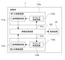
- FIG. 2 is a block diagram showing an example configuration of the inspection system 100.
- the mobile object 1 has an imaging device 10, an information processing device 20, and an inspection device 30.
- the imaging device 10 has a first pixel drive circuit 11, a second pixel drive circuit 12, and a timing control circuit 13.
- the first pixel drive circuit 11 images a first imaging area.
- the second pixel drive circuit 12 images a second imaging area.
- the first pixel drive circuit 11 and the second pixel drive circuit 12 image their respective imaging areas according to control signals output from the timing control circuit 13.
- the timing control circuit 13 outputs a control signal to each of the first pixel drive circuit 11 and the second pixel drive circuit 12.
- the control signal is output based on a synchronization signal output from the control unit 22 of the information processing device 20, which will be described later.
- the information processing device 20 has an acquisition unit 21, a control unit 22, a comparison unit 23, a calculation unit 24, and an output unit 25.
- the information processing device 20 is a processor composed of an MPU (Micro Processing Unit), a CPU (Central Processing Unit), etc.
- the acquisition unit 21 acquires captured images of at least two or more imaging regions.
- the acquisition unit 21 acquires a first captured image that shows a first imaging region captured by the first pixel driving circuit 11, and a second captured image that shows a second imaging region captured by the second pixel driving circuit 12.
- the control unit 22 controls the timing at which the first captured image and the second captured image are captured. In this embodiment, the control unit 22 controls the timing at which the images are captured by outputting a synchronization signal to the timing control circuit 13. Typically, the control unit 22 controls the image so that the inspection object X (see FIG. 1) captured in the first imaging area is captured before passing through the second imaging area.
- Figure 3 shows an example of the imaging timing in each imaging area.
- the moving object 1 since the moving object 1 is moving, the subject also appears to be moving. For this reason, it is desirable for the imaging device 10 to operate using a global shutter. Also, the imaging time must be the same so that the image quality does not change in the first imaging area and the second imaging area. For this reason, in this embodiment, the first pixel driving circuit 11 and the second pixel driving circuit 12 are capable of performing global shutter operation separately.
- the control unit 22 also provides a delay time 35 to the timing of capturing an image of the second imaging area based on the expected speed range of the moving body 1 and the imaging range (the first imaging area, the second imaging area, or the area obtained by adding the first imaging area and the second imaging area) as shown in FIG. 3A.
- the control unit 22 outputs a synchronization signal supplied to the second pixel driving circuit 12 so that the timing of capturing an image is delayed compared to the synchronization signal (control signal) supplied to the first pixel driving circuit 11.
- the comparison unit 23 compares the first captured image and the second captured image. In this embodiment, a comparison is made to determine whether the position of the inspection object captured in the first captured image matches the position of the inspection object captured in the second captured image.
- FIG. 4 is a flowchart showing a comparison between a first captured image and a second captured image.
- FIG. 5 is a diagram showing a schematic diagram of a match between a first captured image and a second captured image.
- FIG. 5A is a diagram showing an example in which the moving body has a constant traveling direction.
- FIG. 5B is a diagram showing an example in which the moving body has an inconstant traveling direction.
- the acquisition unit 21 acquires and records a first captured image of the first imaging area (steps 101 and 102).
- the acquisition unit 21 also acquires a second captured image of the second imaging area (step 103).
- a first captured image 40 and a second captured image 45a are acquired.
- the first captured image 40 shows the inspection object A
- the second captured image 45a does not show the inspection object A.
- the comparison unit 23 compares the first captured image 40 and the second captured image 45a (step 104) and, since they do not match (NO in step 104), the total count and the mismatch count are incremented by one (step 105).
- the second captured image 45b is captured (step 103).
- the first captured image 40 and the second captured image 45b do not match (NO in step 104), so the total count and the mismatch count are incremented (step 105). In other words, the total count and the mismatch count become 2.
- the comparison unit 23 compares the coordinates of the test object A in the first captured image 40 with the coordinates of the test object A in the second captured image 45d and determines that they match if they are below a predetermined threshold.
- the recorded first captured image 40 can be said to be a reference image for comparison with the second captured image.
- the second captured image is updated until it matches this reference first captured image 40.
- the comparison unit 23 outputs the first captured image 40 and the second captured image 45d when they match, and the mismatch count (step 106). That is, the number of counts until the captured images showing the inspection object A match (3 counts in FIG. 5), and the movement amount y, which is the amount that the inspection object A has moved until they match, are output to the calculation unit 24.
- the mismatch count is reset (step 107).
- the first captured image 50 is acquired to move test object B (step 101).
- the total count and the mismatch count are added together, as shown in FIG. 5B, so that the total count becomes 5 and the mismatch count becomes 1.
- the traveling direction of the moving object 1 is constant, such as when the moving object moves along a track as shown in Figure 5A, the inspection object A moves in the same direction as the traveling direction.
- the traveling direction of the moving object 1 is not necessarily constant.
- the moving direction of the moving object 1 is not constant, so the inspection object B also moves in a direction different from the moving direction (see dashed arrow).
- the comparison unit 23 extracts a unique pattern when comparing the first captured image with the second captured image.
- the unique pattern is information that indicates the characteristics of the inspection object 5.
- the unique pattern includes the feature points, size, shape, color, etc. of the inspection object 5.
- the comparison unit 23 determines that the first captured image and the second captured image match. Note that the comparison may also be performed using other methods such as image recognition or information other than that of the inspection target that appears in the captured image.
- steps 103 to 105 are repeated until the total count reaches 7. That is, when the total count is 7 and the mismatch count is 3, the first captured image 50 and the second captured image 55c match (YES in step 104). Furthermore, when a unique pattern is extracted, the comparison unit outputs the count number and the difference in pixel positions in the X and Y directions of the inspection target to the calculation unit 24.
- the calculation unit 24 calculates speed information of the moving object 1 based on the count number output by the comparison unit 23 and the first and second captured images. For example, the calculation unit 24 calculates time from the operating frame rate of the imaging device 10 and the count number. The calculation unit 24 also calculates the amount of movement of the moving object 1 from the start (the moment imaging begins) based on the total count number. The calculation unit 24 also calculates the speed of the moving object 1 at that time based on the mismatch count number.
- the amount of movement in the case of FIG. 5B is the difference between the X and Y coordinates, assuming that the X and Y axes are set at the origin of the inspection object in the first captured image, which serves as the reference.
- the calculation unit sets a feature point in the inspection object in the first captured image as the origin, and calculates the amount of movement based on the difference in X and Y coordinates between that feature point and the corresponding feature point of the inspection object in the second captured image.
- the information processing device 20 obtains images of at least two or more imaging areas, compares the images whose imaging timing has been controlled, and calculates the speed information of the moving body 1 based on the comparison result. This makes it possible to detect the exact location of the damage.
- the second information processing device 120b Based on this synchronization signal S1a, the second information processing device 120b outputs a synchronization signal S1b that controls the timing of capturing an image of the second imaging area to the timing control circuit 112b. As in the first embodiment, the second information processing device 120b may set a delay time for the synchronization signal S1a.
- two imaging devices may be controlled by one information processing device.
- the information processing device 120 outputs a synchronization signal S1a to the first imaging device 110a and outputs a synchronization signal S1b to the second imaging device 110b.
- a unique pattern is extracted when the moving body 1 does not move in a constant direction.
- various matching conditions for the inspection target may be set for various movements of the moving body 1, such as rotation, ascent, descent, etc., or various changes during the inspection, such as a change in the orientation of the imaging device 10.
- the EVS is a sensor that asynchronously detects changes in pixel luminance and outputs event data.
- event data is data that includes the coordinates (X coordinate, Y coordinate) of the pixel where the luminance change occurred, the time when the change was detected, and the polarity of the luminance change.
- Figure 9 is a schematic diagram showing the imaging area in an EVS.
- EVS can detect luminance changes on a pixel-by-pixel basis. By treating this pixel-by-pixel area as an imaging area, it is possible to compare captured images that depict that imaging area.
- the comparison unit 23 determines whether the nth captured image 140 consisting of the nth pixel matches the (n+1)th captured image 145 consisting of the n+1th pixel. In this case, the total count is counted in timestamp units, not in sensor frame units. In this way, the use of EVS allows detection in pixel units, making high-speed and high-resolution detection possible.
- control unit comparison unit, calculation unit, etc.
- comparison flowcharts, etc. described with reference to the drawings are merely one embodiment, and can be modified as desired without departing from the spirit of this technology. In other words, any other configuration, algorithm, etc., for implementing this technology may be adopted.
- the present technology can also be configured as follows.
- an acquisition unit that acquires captured images of at least two or more imaging regions;
- a control unit that controls a timing at which the captured image is captured;
- a comparison unit that compares the acquired captured images;
- a calculation unit that calculates speed information of the moving object based on a comparison result by the comparison unit.
- the information processing device (1), The imaging area is disposed parallel to a traveling direction of the moving body.
- the information processing device according to (2), The control unit outputs a first control signal that controls a timing at which a first imaging area arranged in the direction of travel is imaged, and outputs a second control signal that controls a timing at which a second imaging area arranged in the opposite direction to the direction of travel is imaged.
- the control unit controls the second control signal so that the second imaging area is imaged at a timing later than the timing of the first control signal.
- the control unit controls the second control signal based on a speed of the moving object or a size of the imaging area.
- the acquisition unit acquires a first captured image obtained by capturing an image of the first imaging area and a second captured image obtained by capturing an image of the second imaging area; The information processing device, wherein the comparison unit determines whether or not the first captured image and the second captured image match.
- the comparison unit determines whether feature information indicating a feature of the inspection object captured in the first captured image and the second captured image matches.
- the information processing device calculates the velocity information based on a difference between the frames and a movement amount of the inspection object in both the captured images.
- the information processing device according to (6), The information processing device, wherein when the first captured image and the second captured image do not match, the comparison unit increments a count every time the second imaging area is newly imaged.
- the comparison result includes a total count number that is added up until the first captured image and the second captured image match, The calculation unit calculates the speed information of the moving object based on the total count number.
- the information processing device according to (2), The information processing device, wherein each of the imaging regions has the same length in the traveling direction.
- the information processing device is equipped with the information processing device.
- (16) Acquire captured images of at least two or more imaging regions; Controlling the timing at which the captured image is captured; Comparing the captured images,
- Reference Signs List 1 Mobile body 5: Inspection target 10: Mobile body 20: Information processing device 21: Acquisition unit 22: Control unit 23: Comparison unit 24: Calculation unit 30: Inspection device 100: Inspection system
Landscapes
- Physics & Mathematics (AREA)
- Engineering & Computer Science (AREA)
- Electromagnetism (AREA)
- Power Engineering (AREA)
- General Physics & Mathematics (AREA)
- Investigating Materials By The Use Of Optical Means Adapted For Particular Applications (AREA)
Abstract
本技術の一形態に係る情報処理装置は、取得部と、制御部と、比較部と、算出部とを具備する。前記取得部は、少なくとも2つ以上の撮像領域を撮像した撮像画像を取得する。前記制御部は、前記撮像画像が撮像されるタイミングを制御する。前記比較部は、取得された前記撮像画像を比較する。前記算出部は、前記比較部による比較結果に基づいて、移動体の速度情報を算出する。これにより、損傷の正確な位置を検知することが可能となる。
Description
本技術は、物体や軌道等の損傷の位置特定に適用可能な情報処理装置、情報処理方法、及びプログラムに関する。
特許文献1では、車両の走行中の運転情報、車両の加速度、及び車両の走行位置の検出が可能な軌道検査装置について記載される。この軌道検査装置では、加速度の変化と走行位置とに基づき軌道の不整位置を算出し、軌道損傷の可能性を推定し、走行位置から損傷した可能性のある位置を特定する。これにより、軌道の不整位置を早期に発見でき、高い安全性を確保することが図られている(特許文献1の明細書段落[0009]~[0020]図1、2等)。
このような、損傷の正確な位置を検知することが可能な情報処理装置、情報処理方法、及びプログラムが求められている。
以上のような事情に鑑み、本技術の目的は、損傷の正確な位置を検知することが可能な情報処理装置、情報処理方法、及びプログラムを提供することにある。
上記目的を達成するため、本技術の一形態に係る情報処理装置は、取得部と、制御部と、比較部と、算出部とを具備する。
前記取得部は、少なくとも2つ以上の撮像領域を撮像した撮像画像を取得する。
前記制御部は、前記撮像画像が撮像されるタイミングを制御する。
前記比較部は、取得された前記撮像画像を比較する。
前記算出部は、前記比較部による比較結果に基づいて、移動体の速度情報を算出する。
前記取得部は、少なくとも2つ以上の撮像領域を撮像した撮像画像を取得する。
前記制御部は、前記撮像画像が撮像されるタイミングを制御する。
前記比較部は、取得された前記撮像画像を比較する。
前記算出部は、前記比較部による比較結果に基づいて、移動体の速度情報を算出する。
この情報処理装置では、少なくとも2つ以上の撮像領域を撮像した撮像画像が取得され、撮像されるタイミングが制御された撮像画像が比較され、比較結果に基づいて移動体の速度情報が算出される。これにより、損傷の正確な位置を検知することが可能となる。
前記撮像領域は、前記移動体の進行方向と平行に配置されてもよい。
前記制御部は、前記進行方向側に配置される第1の撮像領域が撮像されるタイミングを制御する第1の制御信号を出力し、前記進行方向とは逆方向側に配置される第2の撮像領域が撮像されるタイミングを制御する第2の制御信号を出力してもよい。
前記制御部は、前記第1の制御信号よりも遅いタイミングで前記第2の撮像領域が撮像されるように前記第2の制御信号を制御してもよい。
前記制御部は、前記移動体の速度、又は前記撮像領域の大きさに基づいて、前記第2の制御信号を制御してもよい。
前記取得部は、前記第1の撮像領域を撮像した第1の撮像画像と、前記第2の撮像領域を撮像した第2の撮像画像とを取得し手もよい。この場合、前記比較部は、前記第1の撮像画像と前記第2の撮像画像とが一致するか否かを判定してもよい。
前記比較部は、前記第1の撮像画像及び前記第2の撮像画像に写る前記検査対象の特徴を示す特徴情報が一致するか否かを判定してもよい。
前記特徴情報は、前記検査対象の特徴点、サイズ、形状、又は色の少なくとも1つを含んでもよい。
前記比較結果は、前記第1の撮像画像及び前記第2の撮像画像が一致した際の両者の撮像時におけるフレームの差分と、前記第1の撮像画像及び前記第2の撮像画像が一致した際の両者の撮像画像とを含んでもよい。
前記算出部は、前記フレームの差分に基づいて、前記移動体の速度情報を算出してもよい。
前記算出部は、前記フレームの差分と、前記両者の撮像画像における前記検査対象の移動量とに基づいて、前記速度情報を算出してもよい。
前記比較部は、前記第1の撮像画像と前記第2の撮像画像とが一致しない場合、新たに前記第2の撮像領域が撮像される度にカウントを加算してもよい。
前記比較結果は、前記第1の撮像画像と前記第2の撮像画像とが一致するまで加算された総カウント数を含んでもよい。この場合、前記算出部は、前記総カウント数に基づいて、前記移動体の前記速度情報を算出してもよい。
前記撮像領域は、前記撮像領域の各々が前記進行方向における長さが同一であってもよい。
前記移動体は、前記情報処理装置を搭載してもよい。
本技術の一形態に係る情報処理方法は、コンピュータシステムが実行する情報処理方法であって、少なくとも2つ以上の撮像領域を撮像した撮像画像が取得されることを含む。
前記撮像画像が撮像されるタイミングを制御する。
取得された前記撮像画像を比較する。
前記比較部による比較結果に基づいて、移動体の速度情報を算出する
前記撮像画像が撮像されるタイミングを制御する。
取得された前記撮像画像を比較する。
前記比較部による比較結果に基づいて、移動体の速度情報を算出する
本技術の一形態に係るプログラムは、コンピュータシステムに以下のステップを実行させる。
少なくとも2つ以上の撮像領域を撮像した撮像画像を取得するステップ。
前記撮像画像が撮像されるタイミングを制御するステップ。
取得された前記撮像画像を比較するステップ。
前記比較部による比較結果に基づいて、移動体の速度情報を算出するステップ。
少なくとも2つ以上の撮像領域を撮像した撮像画像を取得するステップ。
前記撮像画像が撮像されるタイミングを制御するステップ。
取得された前記撮像画像を比較するステップ。
前記比較部による比較結果に基づいて、移動体の速度情報を算出するステップ。
以下、本技術に係る実施形態を、図面を参照しながら説明する。
<第1の実施形態>
図1は、本技術の第1の実施形態に係る検査システム100を模式的に示す図である。図1Aは、検査システムの一例を示す図である。図1Bは、撮像領域を模式的に示す図である。
図1は、本技術の第1の実施形態に係る検査システム100を模式的に示す図である。図1Aは、検査システムの一例を示す図である。図1Bは、撮像領域を模式的に示す図である。
図1に示すように、検査システム100は、移動体1、移動体1に搭載される撮像装置10、情報処理装置20、及び検査装置30を有する。検査システム100は、撮像装置10を用いることで、検査対象5の損傷個所の有無を検査する。
典型的には、検査対象5は、軌道(線路)、道路、トンネル、滑走路、橋梁、住宅、ダム、下水道、電柱、電線、標識等のインフラ(Infrastructure)に関わる様々な施設や設備を含む。また検査対象5には、上記のインフラにおける、損傷(ひび割れ、腐食、水漏れ等)が起きている可能性のある箇所(候補)も含まれる。
なお検査対象5には、インフラ以外の物体も含まれてもよい。例えば、インフラに接触している木々や倒木、鳥のフンや巣、落石等のインフラの支障又はその原因となり得る物体が含まれてもよい。
移動体1は、検査対象5となる物体の形状に沿って、移動可能であることが望ましい。例えば、軌道の検査を行う場合は電車、道路やトンネルの検査を行う場合は車、電柱や橋梁の検査を行う場合はドローン等の検査対象の種類に応じて様々な移動体が用いられてもよい。
撮像装置10は、検査対象5を撮像する。本実施形態では、撮像装置10は、移動体1に搭載され、少なくとも2つ以上の撮像領域を撮像可能である。
図1Bに示すように、撮像領域は、進行方向に平行に、撮像装置10(センサ)内で撮像領域が分割された領域である。以下、進行方向側に配置される領域を第1の撮像領域、進行方向とは逆方向側に配置される領域を第2の撮像領域と記載する。
例えば図1Bの左図は、Nフレーム目に撮像された撮像画像であり、第1の撮像領域6内に検査対象Xが撮像されている。また図1Bの右図では、N+Tフレーム目に撮像された撮像画像であり、第2の撮像領域7内に検査対象Xが撮像されている。
この場合、情報処理装置20は、第1の撮像領域6で撮像された撮像画像と、第2の撮像領域7で撮像された撮像画像とが一致するまでのフレーム数に基づいて、移動体1の速度の推定を行う。この推定された移動体1の速度情報及び検査対象Xを含む画像情報が、検査装置30に供給される。
また本実施形態では、第1の撮像領域6及び第2の撮像領域7は、進行方向における長さ(撮像範囲)が等しくなるように設定される。例えば、撮像したい領域に合わせて撮像装置10の取り付け位置やレンズ等の光学系を調整することで第1の撮像領域6及び第2の撮像領域7が均等になるように設定される。なお、撮像領域のサイズ(画素数)や形状、数は限定されない。
検査装置30は、検査対象5の損傷の有無を検査する。例えば、検査装置30は、移動体1の移動位置を検出する位置検出部、移動体1の速度情報(速度や加速度を含む)を検出する速度検出部、損傷の種類や位置情報を記録する記録部等を有する。
図2は、検査システム100の構成例を示すブロック図である。
図2に示すように、移動体1は、撮像装置10、情報処理装置20、及び検査装置30を有する。
撮像装置10は、第1の画素駆動回路11、第2の画素駆動回路12、及びタイミング制御回路13を有する。第1の画素駆動回路11は、第1の撮像領域を撮像する。第2の画素駆動回路12は、第2の撮像領域を撮像する。本実施形態では、第1の画素駆動回路11及び第2の画素駆動回路12は、タイミング制御回路13から出力される制御信号に従って、それぞれの撮像領域を撮像する。
タイミング制御回路13は、第1の画素駆動回路11及び第2の画素駆動回路12のそれぞれに制御信号を出力する。本実施形態では、後述する情報処理装置20の制御部22から出力される同期信号に基づいて、制御信号を出力する。
情報処理装置20は、取得部21、制御部22、比較部23、算出部24、及び出力部25を有する。例えば、情報処理装置20は、MPU(Micro Processing Unit)、CPU(Central Processing Unit)等で構成されるプロセッサである。
取得部21は、少なくとも2つ以上の撮像領域を撮像した撮像画像を取得する。本実施形態では、取得部21は、第1の画素駆動回路11により撮像された第1の撮像領域を写す第1の撮像画像と、第2の画素駆動回路12により撮像された第2の撮像領域を写す第2の撮像画像とを取得する。
制御部22は、第1の撮像画像及び第2の撮像画像が撮像されるタイミングを制御する。本実施形態では、制御部22は、タイミング制御回路13に同期信号を出力することで、撮像されるタイミングを制御する。典型的には、制御部22は、第1の撮像領域に写る検査対象X(図1参照)が第2の撮像領域を通過する前に撮像されるように制御される。
図3は、各撮像領域における撮像タイミングの一例を示す図である。
本実施形態では、移動体1が移動をしているため、被写体も移動しているように見える。このため、撮像装置10は、グローバルシャッター(Global Shutter)動作であることが望ましい。また第1の撮像領域及び第2の撮像領域で画品位が変わらないように撮像時間は同一とする必要がある。そのため、本実施形態では、第1の画素駆動回路11と、第2の画素駆動回路12とで個別にグローバルシャッター動作を可能とする。
また制御部22は、図3Aに示すように、移動体1の想定される速度域と撮像範囲(第1の撮像領域、第2の撮像領域、又は第1の撮像領域と第2の撮像領域とを加えた領域)とに基づいて、第2の撮像領域を撮像するタイミングにディレイ時間35を与える。すなわち、制御部22は、第1の画素駆動回路11に供給される同期信号(制御信号)と比べて撮像するタイミングが遅くなるように、第2の画素駆動回路12に供給される同期信号を出力する。
なおグローバルシャッター動作は、一斉に画素を駆動するため電源からグランド間にノイズが発生する。本実施形態では、撮像領域ごとにグローバルシャッター動作が行われるため、図3Bに示すように、撮像領域に応じて電源とグランドとを分割することが望ましい。
なお、ディレイ時間は任意に設定されてもよい。同時(ディレイ時間=0)でもよいし、撮影画像や移動体の移動速度に基づいて、適宜設定されてもよい。
比較部23は、第1の撮像画像及び第2の撮像画像を比較する。本実施形態では、第1の撮像画像に写る検査対象の位置と、第2の撮像画像に写る検査対象の位置とが一致するか否かが比較される。
ここで、図4及び図5を用いて、比較部による第1の撮像画像及び第2の撮像画像の比較方法を例示する。
図4は、第1の撮像画像及び第2の撮像画像の比較を示すフローチャートである。図5は、第1の撮像画像及び第2の撮像画像の一致を模式的に示す図である。図5Aは、移動体の進行方向が一定である場合の例を示す図である。図5Bは、移動体の進行方向が一定でない場合の例を示す図である。
図4に示すように、取得部21により、第1の撮像領域が撮像された第1の撮像画像が取得され、記録される(ステップ101、102)。また取得部21により、第2の撮像領域が撮像された第2の撮像画像が取得される(ステップ103)。
例えば、図5Aに示すように、ステップ101及びステップ102では、第1の撮像画像40及び第2の撮像画像45aが取得される。図5Aでは、第1の撮像画像40では、検査対象Aが写っており、第2の撮像画像45aには検査対象Aが写っていない状態である。
この場合、比較部23により、第1の撮像画像40及び第2の撮像画像45aが比較され(ステップ104)、一致していないため(ステップ104のNO)、トータルカウント及び不一致カウントが1つ加算される(ステップ105)。
次に、トータルカウント及び不一致カウントが1の時に、第2の撮像画像45bが撮像される(ステップ103)。図5Aに示すように、この場合も第1の撮像画像40及び第2の撮像画像45bが一致しないため(ステップ104のNO)、トータルカウント及び不一致カウントが加算される(ステップ105)。すなわち、トータルカウント及び不一致カウントが2となる。
図5Aでは、トータルカウント及び不一致カウントが4の時に、第1の撮像画像40及び第2の撮像画像45dが一致する(ステップ104のYES)。例えば、比較部23は、第1の撮像画像40における検査対象Aの座標と、第2の撮像画像45dにおける検査対象Aの座標とを比べて所定の閾値以下であれば、一致すると判定する。つまり、記録された第1の撮像画像40は、第2の撮像画像と比較するための基準となる画像ともいえる。この基準となる第1の撮像画像40と一致するまで、第2の撮像画像は更新される。
この場合、比較部23により、一致した際の第1の撮像画像40及び第2の撮像画像45dと、不一致カウントとが出力される(ステップ106)。すなわち、検査対象Aが写る撮像画像が一致するまでのカウント数(図5では3カウント分)と、一致するまでに検査対象Aが移動した量である移動量yとが算出部24に出力される。
また撮像画像及びカウント数の出力が終了したら、不一致カウントがリセットされる(ステップ107)。
また検査対象Aの比較が終了した後に、検査対象Bを移す第1の撮像画像50が取得されたとする(ステップ101)。この場合、第1の撮像画像50と第2の撮像画像55aとが一致しないため(ステップ104のNO)、図5Bに示すように、トータルカウント及び不一致カウントが加算されることで、トータルカウントが5、不一致カウントが1となる。
ここで図5Aのように軌道上に沿って移動体が移動する等の移動体1の進行方向が一定である場合、検査対象Aは進行方向と同じ方向に移動する。しかしながら、道路等の損傷箇所の位置を特定しようとする場合、移動体1の進行方向が一定になるとは限らない。
例えば図5Bでは、移動体1の進行方向が一定ではないため、検査対象Bも進行方向とは異なる方向に移動する(破線矢印参照)。
この場合、比較部23は、第1の撮像画像と第2の撮像画像とを比較する際に、特異パターンを抽出する。特異パターンとは、検査対象5の特徴を示す情報である。例えば、特異パターンは、検査対象5の特徴点やサイズ、形状、色等を含む。
例えば比較部23は、第1の撮像画像に写る検査対象5の特異パターンと、第2の撮像画像に写る検査対象5の特異パターンとの一致度合いが所定の閾値を超える場合、第1の撮像画像と第2の撮像画像とが一致すると判定する。なお、これ以外にも、画像認識や検査対象以外の撮像画像に写る情報等によって比較が行われてもよい。
図5Bでは、トータルカウントが7になるまでステップ103~105が繰り返される。すなわち、トータルカウントが7、不一致カウントが3の時に、第1の撮像画像50及び第2の撮像画像55cが一致する(ステップ104のYES)。また特異パターンの抽出が行われた場合、比較部は、カウント数、及び検査対象のX及びY方向の画素位置の差分を算出部24に出力する。
なお図4のフローチャートは、検査が終了するまで繰り返し行われる(ステップ107からステップ101へ)。
算出部24は、比較部23により出力されるカウント数と第1及び第2の撮像画像とに基づいて、移動体1の速度情報を算出する。例えば、算出部24は、撮像装置10の動作フレームレートとカウント数から時間の算出を行う。また算出部24は、トータルカウント数に基づいて、移動体1のスタート(撮像を始めた瞬間)からどれだけ移動したかの移動量を算出する。また算出部24は、不一致カウント数に基づいて、その時点での移動体1の速度を算出する。
なお図5Bの場合の移動量は、基準となる第1の撮像画像の検査対象を原点にX軸Y軸を仮定し、X座標及びY座標の差分となる。具体的には、算出部は、第1の撮像画像の検査対象における特徴点を原点とし、その特徴点に対応する第2の撮像画像の検査対象の特徴点とのXY座標における差分に基づいて、移動量を算出する。
出力部25は、出力された撮像画像、及び算出された移動体1の速度情報を検査装置30へと出力する。検査装置30は、この撮像画像及び速度情報に基づいて、検査対象5の損傷の有無を検査する。
以上、本実施形態に係る情報処理装置20は、少なくとも2つ以上の撮像領域を撮像した撮像画像が取得され、撮像されるタイミングが制御された撮像画像が比較され、比較結果に基づいて移動体1の速度情報が算出される。これにより、損傷の正確な位置を検知することが可能となる。
従来、軌道の損傷を検査する際には、撮影装置を搭載した移動体にGPS用のアンテナや加速度センサが搭載されることで、移動体の移動速度や損傷箇所の位置が特定された。しかしながら、GPSや加速度のデータを収集するための機構が別に必要となり、装置が複雑化してしまう。
本技術では、移動体にGPS用のアンテナや加速度センサが搭載されず、移動体の進行方向に平行に少なくとも2つ以上の撮像領域を撮像することで損傷の位置特定が行われる。これにより、GPSや加速度センサを用いる必要がなくなり装置の簡略化が可能となる。また撮像領域を分割し、それぞれの撮像パターンが一致する時間で速度推定も行うことで損傷の位置特定の精度を向上させることができる。
<第2の実施形態>
本技術に係る第2の実施形態の情報処理装置について説明する。これ以降の説明では、上記の実施形態で説明した情報処理装置20における構成及び作用と同様な部分については、その説明を省略又は簡略化する。
本技術に係る第2の実施形態の情報処理装置について説明する。これ以降の説明では、上記の実施形態で説明した情報処理装置20における構成及び作用と同様な部分については、その説明を省略又は簡略化する。
上記の実施形態では、1つの撮像装置の撮像領域を分割することで2つの撮像領域が撮像された。これに限定されず、2つの撮像装置を用いることで2つの撮像領域を撮像してもよい。この場合、2つの撮像装置は、進行方向に平行に並んで配置されることが望ましい。
図6は、第2の実施形態に係る検査システムの構成例を示すブロック図である。なお図6では、情報処理装置を簡略化して図示している。
図6に示すように、移動体1には、第1の撮像装置110a及び第2の撮像装置110bが搭載される。また移動体1は、第1の情報処理装置120a及び第2の情報処理装置120bを具備し、第1の情報処理装置120aにより第1の撮像装置110aが制御され、第2の情報処理装置120bにより第2の撮像装置110bが制御される。なお第1の情報処理装置120a及び第2の情報処理装置120bは、第1の実施形態における情報処理装置20と同様の構成である。
第2の実施形態では、第1の撮像装置110aにより第1の撮像領域が撮像され、第2の撮像装置110bにより第2の撮像領域が撮像される。すなわち、画素駆動回路111aは、第1の画素駆動回路11として機能し、画素駆動回路111bは、第2の画素駆動回路12として機能する。
またタイミング制御回路112aは、情報処理装置120aからの同期信号S1aに基づいて、画素駆動回路111aに対して制御信号を出力する。
また第2の実施形態では、第1の情報処理装置120aと第2の情報処理装置120bとの間に同期信号のやり取りが行われる。すなわち、第1の情報処理装置120aは、第1の撮像領域を撮像するタイミングを制御する同期信号S1aを第2の情報処理装置120bへと出力する。
第2の情報処理装置120bは、この同期信号S1aに基づいて、第2の撮像領域を撮像するタイミングを制御する同期信号S1bをタイミング制御回路112bへと出力する。なお、第1の実施形態と同様に、第2の情報処理装置120bは、同期信号S1aに対してディレイ時間を設定してもよい。
なお第2の実施形態では、図4に示す第1の撮像画像及び第2の撮像画像の比較を示すフローチャートについては、第1の情報処理装置120a及び第2の情報処理装置120bのどちらか一方が行ってもよい。
また図7に示すように、2つの撮像装置に対して、1つの情報処理装置により制御が行われてもよい。図7の場合、情報処理装置120は、第1の撮像装置110aへと同期信号S1aを出力し、第2の撮像装置110bへと同期信号S1bを出力する。
<その他の実施形態>
本技術は、以上説明した実施形態に限定されず、他の種々の実施形態を実現することができる。
本技術は、以上説明した実施形態に限定されず、他の種々の実施形態を実現することができる。
上記の実施形態では、同期信号は、情報処理装置から出力された。これに限定されず、図8に示すように同期信号を出力する制御部が撮像装置に含まれてもよい。図8は、撮像装置及び情報処理装置の他の構成例を示すブロック図である。
図8に示すように、撮像装置10は、第1の画素駆動回路11、第2の画素駆動回路12、及びタイミング制御回路13に加えて、制御部22を有する。図8では、タイミング制御回路13は、制御部22から出力される同期信号に基づいて、制御信号を出力する。このように、第1の撮像領域及び第2の撮像領域の撮像されるタイミングは、撮像装置10内で制御が行われてもよい。
上記の実施形態では、ディレイ時間は、移動体1の想定される速度域と撮像範囲に応じて設定された。これに限定されず、ディレイ時間は、トータルカウントや不一致カウント、ステップ106で出力される撮像画像(例えば、第1の撮像画像と第2の撮像画像との一致度合い)等に基づいて、ディレイ時間が適宜設定されてもよい。
上記の実施形態では、移動体1の進行方向が一定でない場合、特異パターンが抽出された。これに限定されず、回転や上昇、下降等の移動体1の様々な移動、又は撮像装置10の向きが変更される等の検査中における種々の変化に対して様々な検査対象の一致条件が設定されてもよい。
上記の実施形態では、トータルカウントが第1の撮像画像及び第2の撮像画像が一致しないことで加算された。これに限定されず、トータルカウントや不一致カウントが状況に応じて加算されなくてもよい。例えば、第1の撮像領域に検査対象5が写っていない場合、トータルカウントをカウントしなくてもよい。すなわち、検査対象の一部又は全てが第1の撮像領域に写っている状況からトータルカウントの加算が行われてもよい。また図4に示すフローチャートでは、検査対象が写っていない場合にも第1の撮像画像及び第2の撮像画像が一致するためステップ106で画像及びカウント数が出力されるが、検査対象が写っているか否かを判定するステップがステップ104のYESからステップ106の間に挿入されてもよい。これにより、データ量の削減が可能となる。
上記の実施形態では、情報処理装置20や検査装置30が移動体1に搭載された。これに限定されず、情報処理装置20や検査装置30が移動体1以外の外部にあってもよい。例えば、移動体1に搭載された撮像装置10からの画像情報が情報処理装置20に有線又は無線を介して送信されることで移動体1の速度情報が算出されてもよい。
上記の実施形態では、2つの撮像領域により比較が行われた。これに限定されず、撮像領域の数は限定されず、少なくとも2つ以上の撮像領域を撮像することで比較が行われてもよい。例えば、撮像装置は、EVS(Event-based Vision Sensor)でもよい。
EVSは、画素の輝度変化を非同期で検出し、イベントデータを出力するセンサである。ここで、イベントデータとは、輝度変化があった画素の座標(X座標、Y座標)、変化を検出した時間、及び輝度変化の極性を含むデータである。
図9は、EVSにおける撮像領域を模式的に示す図である。
図9に示すように、EVSは、画素単位で輝度変化を検出することが可能である。この画素単位の領域を撮像領域として扱うことで、その撮像領域を写す撮像画像を比較することができる。
例えば、図9では、比較部23は、n番目の画素からなる第nの撮像画像140と、n+1番目の画素からなる第(n+1)の撮像画像145とが一致するかを判定する。またこの場合、トータルカウントは、センサフレーム単位ではなく、タイムスタンプ単位でカウントされる。このように、EVSを用いることにより画素単位で検出できるため、高速かつ高精細な検出が可能となる。
各図面を参照して説明した制御部、比較部、算出部等の各構成、比較のフローチャート等はあくまで一実施形態であり、本技術の趣旨を逸脱しない範囲で、任意に変形可能である。すなわち本技術を実施するための他の任意の構成やアルゴリズム等が採用されてよい。
なお、本開示中に記載された効果はあくまで例示であって限定されるものでは無く、また他の効果があってもよい。上記の複数の効果の記載は、それらの効果が必ずしも同時に発揮されるということを意味しているのではない。条件等により、少なくとも上記した効果のいずれかが得られることを意味しており、もちろん本開示中に記載されていない効果が発揮される可能性もある。
以上説明した各形態の特徴部分のうち、少なくとも2つの特徴部分を組み合わせることも可能である。すなわち各実施形態で説明した種々の特徴部分は、各実施形態の区別なく、任意に組み合わされてもよい。
なお、本技術は以下のような構成も採ることができる。
(1)
少なくとも2つ以上の撮像領域を撮像した撮像画像を取得する取得部と、
前記撮像画像が撮像されるタイミングを制御する制御部と、
取得された前記撮像画像を比較する比較部と、
前記比較部による比較結果に基づいて、移動体の速度情報を算出する算出部と
を具備する情報処理装置。
(2)(1)に記載の情報処理装置であって、
前記撮像領域は、前記移動体の進行方向と平行に配置される
情報処理装置。
(3)(2)に記載の情報処理装置であって、
前記制御部は、前記進行方向側に配置される第1の撮像領域が撮像されるタイミングを制御する第1の制御信号を出力し、前記進行方向とは逆方向側に配置される第2の撮像領域が撮像されるタイミングを制御する第2の制御信号を出力する
情報処理装置。
(4)(3)に記載の情報処理装置であって、
前記制御部は、前記第1の制御信号よりも遅いタイミングで前記第2の撮像領域が撮像されるように前記第2の制御信号を制御する
情報処理装置。
(5)(4)に記載の情報処理装置であって、
前記制御部は、前記移動体の速度、又は前記撮像領域の大きさに基づいて、前記第2の制御信号を制御する
情報処理装置。
(6)(3)に記載の情報処理装置であって、
前記取得部は、前記第1の撮像領域を撮像した第1の撮像画像と、前記第2の撮像領域を撮像した第2の撮像画像とを取得し、
前記比較部は、前記第1の撮像画像と前記第2の撮像画像とが一致するか否かを判定する
情報処理装置。
(7)(6)に記載の情報処理装置であって、
前記比較部は、前記第1の撮像画像及び前記第2の撮像画像に写る前記検査対象の特徴を示す特徴情報が一致するか否かを判定する
情報処理装置。
(8)(7)に記載の情報処理装置であって、
前記特徴情報は、前記検査対象の特徴点、サイズ、形状、又は色の少なくとも1つを含む
情報処理装置。
(9)(6)に記載の情報処理装置であって、
前記比較結果は、前記第1の撮像画像及び前記第2の撮像画像が一致した際の両者の撮像時におけるフレームの差分と、前記第1の撮像画像及び前記第2の撮像画像が一致した際の両者の撮像画像とを含む
情報処理装置。
(10)(9)に記載の情報処理装置であって、
前記算出部は、前記フレームの差分に基づいて、前記移動体の速度情報を算出する
情報処理装置。
(11)(10)に記載の情報処理装置であって、
前記算出部は、前記フレームの差分と、前記両者の撮像画像における前記検査対象の移動量とに基づいて、前記速度情報を算出する
情報処理装置。
(12)(6)に記載の情報処理装置であって、
前記比較部は、前記第1の撮像画像と前記第2の撮像画像とが一致しない場合、新たに前記第2の撮像領域が撮像される度にカウントを加算する
情報処理装置。
(13)(12)に記載の情報処理装置であって、
前記比較結果は、前記第1の撮像画像と前記第2の撮像画像とが一致するまで加算された総カウント数を含み、
前記算出部は、前記総カウント数に基づいて、前記移動体の前記速度情報を算出する
情報処理装置。
(14)(2)に記載の情報処理装置であって、
前記撮像領域は、前記撮像領域の各々が前記進行方向における長さが同一である
情報処理装置。
(15)(1)に記載の情報処理装置であって、
前記移動体は、前記情報処理装置を搭載する
情報処理装置。
(16)
少なくとも2つ以上の撮像領域を撮像した撮像画像を取得し、
前記撮像画像が撮像されるタイミングを制御し、
取得された前記撮像画像を比較し、
前記比較部による比較結果に基づいて、移動体の速度情報を算出する
ことをコンピュータシステムが実行する情報処理方法
(17)
少なくとも2つ以上の撮像領域を撮像した撮像画像を取得するステップと、
前記撮像画像が撮像されるタイミングを制御するステップと、
取得された前記撮像画像を比較するステップと、
前記比較部による比較結果に基づいて、移動体の速度情報を算出するステップと
をコンピュータシステムに実行させるプログラム。
(1)
少なくとも2つ以上の撮像領域を撮像した撮像画像を取得する取得部と、
前記撮像画像が撮像されるタイミングを制御する制御部と、
取得された前記撮像画像を比較する比較部と、
前記比較部による比較結果に基づいて、移動体の速度情報を算出する算出部と
を具備する情報処理装置。
(2)(1)に記載の情報処理装置であって、
前記撮像領域は、前記移動体の進行方向と平行に配置される
情報処理装置。
(3)(2)に記載の情報処理装置であって、
前記制御部は、前記進行方向側に配置される第1の撮像領域が撮像されるタイミングを制御する第1の制御信号を出力し、前記進行方向とは逆方向側に配置される第2の撮像領域が撮像されるタイミングを制御する第2の制御信号を出力する
情報処理装置。
(4)(3)に記載の情報処理装置であって、
前記制御部は、前記第1の制御信号よりも遅いタイミングで前記第2の撮像領域が撮像されるように前記第2の制御信号を制御する
情報処理装置。
(5)(4)に記載の情報処理装置であって、
前記制御部は、前記移動体の速度、又は前記撮像領域の大きさに基づいて、前記第2の制御信号を制御する
情報処理装置。
(6)(3)に記載の情報処理装置であって、
前記取得部は、前記第1の撮像領域を撮像した第1の撮像画像と、前記第2の撮像領域を撮像した第2の撮像画像とを取得し、
前記比較部は、前記第1の撮像画像と前記第2の撮像画像とが一致するか否かを判定する
情報処理装置。
(7)(6)に記載の情報処理装置であって、
前記比較部は、前記第1の撮像画像及び前記第2の撮像画像に写る前記検査対象の特徴を示す特徴情報が一致するか否かを判定する
情報処理装置。
(8)(7)に記載の情報処理装置であって、
前記特徴情報は、前記検査対象の特徴点、サイズ、形状、又は色の少なくとも1つを含む
情報処理装置。
(9)(6)に記載の情報処理装置であって、
前記比較結果は、前記第1の撮像画像及び前記第2の撮像画像が一致した際の両者の撮像時におけるフレームの差分と、前記第1の撮像画像及び前記第2の撮像画像が一致した際の両者の撮像画像とを含む
情報処理装置。
(10)(9)に記載の情報処理装置であって、
前記算出部は、前記フレームの差分に基づいて、前記移動体の速度情報を算出する
情報処理装置。
(11)(10)に記載の情報処理装置であって、
前記算出部は、前記フレームの差分と、前記両者の撮像画像における前記検査対象の移動量とに基づいて、前記速度情報を算出する
情報処理装置。
(12)(6)に記載の情報処理装置であって、
前記比較部は、前記第1の撮像画像と前記第2の撮像画像とが一致しない場合、新たに前記第2の撮像領域が撮像される度にカウントを加算する
情報処理装置。
(13)(12)に記載の情報処理装置であって、
前記比較結果は、前記第1の撮像画像と前記第2の撮像画像とが一致するまで加算された総カウント数を含み、
前記算出部は、前記総カウント数に基づいて、前記移動体の前記速度情報を算出する
情報処理装置。
(14)(2)に記載の情報処理装置であって、
前記撮像領域は、前記撮像領域の各々が前記進行方向における長さが同一である
情報処理装置。
(15)(1)に記載の情報処理装置であって、
前記移動体は、前記情報処理装置を搭載する
情報処理装置。
(16)
少なくとも2つ以上の撮像領域を撮像した撮像画像を取得し、
前記撮像画像が撮像されるタイミングを制御し、
取得された前記撮像画像を比較し、
前記比較部による比較結果に基づいて、移動体の速度情報を算出する
ことをコンピュータシステムが実行する情報処理方法
(17)
少なくとも2つ以上の撮像領域を撮像した撮像画像を取得するステップと、
前記撮像画像が撮像されるタイミングを制御するステップと、
取得された前記撮像画像を比較するステップと、
前記比較部による比較結果に基づいて、移動体の速度情報を算出するステップと
をコンピュータシステムに実行させるプログラム。
1…移動体
5…検査対象
10…移動体
20…情報処理装置
21…取得部
22…制御部
23…比較部
24…算出部
30…検査装置
100…検査システム
5…検査対象
10…移動体
20…情報処理装置
21…取得部
22…制御部
23…比較部
24…算出部
30…検査装置
100…検査システム
Claims (17)
- 少なくとも2つ以上の撮像領域を撮像した撮像画像を取得する取得部と、
前記撮像画像が撮像されるタイミングを制御する制御部と、
取得された前記撮像画像を比較する比較部と、
前記比較部による比較結果に基づいて、移動体の速度情報を算出する算出部と
を具備する情報処理装置。 - 請求項1に記載の情報処理装置であって、
前記撮像領域は、前記移動体の進行方向と平行に配置される
情報処理装置。 - 請求項2に記載の情報処理装置であって、
前記制御部は、前記進行方向側に配置される第1の撮像領域が撮像されるタイミングを制御する第1の制御信号を出力し、前記進行方向とは逆方向側に配置される第2の撮像領域が撮像されるタイミングを制御する第2の制御信号を出力する
情報処理装置。 - 請求項3に記載の情報処理装置であって、
前記制御部は、前記第1の制御信号よりも遅いタイミングで前記第2の撮像領域が撮像されるように前記第2の制御信号を制御する
情報処理装置。 - 請求項4に記載の情報処理装置であって、
前記制御部は、前記移動体の速度、又は前記撮像領域の大きさに基づいて、前記第2の制御信号を制御する
情報処理装置。 - 請求項3に記載の情報処理装置であって、
前記取得部は、前記第1の撮像領域を撮像した第1の撮像画像と、前記第2の撮像領域を撮像した第2の撮像画像とを取得し、
前記比較部は、前記第1の撮像画像と前記第2の撮像画像とが一致するか否かを判定する
情報処理装置。 - 請求項6に記載の情報処理装置であって、
前記比較部は、前記第1の撮像画像及び前記第2の撮像画像に写る前記検査対象の特徴を示す特徴情報が一致するか否かを判定する
情報処理装置。 - 請求項7に記載の情報処理装置であって、
前記特徴情報は、前記検査対象の特徴点、サイズ、形状、又は色の少なくとも1つを含む
情報処理装置。 - 請求項6に記載の情報処理装置であって、
前記比較結果は、前記第1の撮像画像及び前記第2の撮像画像が一致した際の両者の撮像時におけるフレームの差分と、前記第1の撮像画像及び前記第2の撮像画像が一致した際の両者の撮像画像とを含む
情報処理装置。 - 請求項9に記載の情報処理装置であって、
前記算出部は、前記フレームの差分に基づいて、前記移動体の速度情報を算出する
情報処理装置。 - 請求項10に記載の情報処理装置であって、
前記算出部は、前記フレームの差分と、前記両者の撮像画像における前記検査対象の移動量とに基づいて、前記速度情報を算出する
情報処理装置。 - 請求項6に記載の情報処理装置であって、
前記比較部は、前記第1の撮像画像と前記第2の撮像画像とが一致しない場合、新たに前記第2の撮像領域が撮像される度にカウントを加算する
情報処理装置。 - 請求項12に記載の情報処理装置であって、
前記比較結果は、前記第1の撮像画像と前記第2の撮像画像とが一致するまで加算された総カウント数を含み、
前記算出部は、前記総カウント数に基づいて、前記移動体の前記速度情報を算出する
情報処理装置。 - 請求項2に記載の情報処理装置であって、
前記撮像領域は、前記撮像領域の各々が前記進行方向における長さが同一である
情報処理装置。 - 請求項1に記載の情報処理装置であって、
前記移動体は、前記情報処理装置を搭載する
情報処理装置。 - 少なくとも2つ以上の撮像領域を撮像した撮像画像を取得し、
前記撮像画像が撮像されるタイミングを制御し、
取得された前記撮像画像を比較し、
前記比較部による比較結果に基づいて、移動体の速度情報を算出する
ことをコンピュータシステムが実行する情報処理方法 - 少なくとも2つ以上の撮像領域を撮像した撮像画像を取得するステップと、
前記撮像画像が撮像されるタイミングを制御するステップと、
取得された前記撮像画像を比較するステップと、
前記比較部による比較結果に基づいて、移動体の速度情報を算出するステップと
をコンピュータシステムに実行させるプログラム。
Applications Claiming Priority (2)
| Application Number | Priority Date | Filing Date | Title |
|---|---|---|---|
| JP2023190017 | 2023-11-07 | ||
| JP2023-190017 | 2023-11-07 |
Publications (1)
| Publication Number | Publication Date |
|---|---|
| WO2025100141A1 true WO2025100141A1 (ja) | 2025-05-15 |
Family
ID=95695261
Family Applications (1)
| Application Number | Title | Priority Date | Filing Date |
|---|---|---|---|
| PCT/JP2024/035633 Pending WO2025100141A1 (ja) | 2023-11-07 | 2024-10-04 | 情報処理装置、情報処理方法、及びプログラム |
Country Status (1)
| Country | Link |
|---|---|
| WO (1) | WO2025100141A1 (ja) |
Citations (4)
| Publication number | Priority date | Publication date | Assignee | Title |
|---|---|---|---|---|
| US20040221790A1 (en) * | 2003-05-02 | 2004-11-11 | Sinclair Kenneth H. | Method and apparatus for optical odometry |
| JP2017207379A (ja) * | 2016-05-19 | 2017-11-24 | 株式会社小野測器 | 速度測定装置 |
| JP2018092065A (ja) * | 2016-12-06 | 2018-06-14 | コニカミノルタ株式会社 | 画像形成装置 |
| JP2023029441A (ja) * | 2018-09-14 | 2023-03-03 | 株式会社リコー | 計測装置、計測システムおよび車両 |
-
2024
- 2024-10-04 WO PCT/JP2024/035633 patent/WO2025100141A1/ja active Pending
Patent Citations (4)
| Publication number | Priority date | Publication date | Assignee | Title |
|---|---|---|---|---|
| US20040221790A1 (en) * | 2003-05-02 | 2004-11-11 | Sinclair Kenneth H. | Method and apparatus for optical odometry |
| JP2017207379A (ja) * | 2016-05-19 | 2017-11-24 | 株式会社小野測器 | 速度測定装置 |
| JP2018092065A (ja) * | 2016-12-06 | 2018-06-14 | コニカミノルタ株式会社 | 画像形成装置 |
| JP2023029441A (ja) * | 2018-09-14 | 2023-03-03 | 株式会社リコー | 計測装置、計測システムおよび車両 |
Similar Documents
| Publication | Publication Date | Title |
|---|---|---|
| Chen et al. | Inexpensive multimodal sensor fusion system for autonomous data acquisition of road surface conditions | |
| KR100898061B1 (ko) | 하이브리드 터널 스캐닝 장치 | |
| US20200349743A1 (en) | Image synthesizing system and image synthesizing method | |
| KR20030080285A (ko) | 차량의 대기 길이 측정 장치 및 방법 | |
| CN202147697U (zh) | 磁浮式轨道巡检车高速在线视频检测装置 | |
| CN109242035B (zh) | 车底故障检测装置及方法 | |
| WO2020194539A1 (ja) | 構造物の変位計測装置 | |
| KR20210062454A (ko) | 선로 검사 장치 및 선로 검사 방법 | |
| JP6699323B2 (ja) | 電車設備の三次元計測装置及び三次元計測方法 | |
| CN113960066B (zh) | 一种基于三维线扫描的受电弓识别抓拍检测装置及方法 | |
| JP2021179441A (ja) | 滑走路照明灯の検査装置及び滑走路照明灯の検査方法 | |
| CN107506753B (zh) | 一种面向动态视频监控的多车辆跟踪方法 | |
| CN104267209B (zh) | 一种基于虚拟线圈的高速公路视频测速方法及系统 | |
| CN112441064B (zh) | 轨道探伤方法、装置、系统和自动化巡检车 | |
| KR20220120211A (ko) | 교통량 측정을 위한 딥러닝 기반의 드론 영상 분석 시스템 | |
| JP4440809B2 (ja) | パンタグラフ周辺支障物検出装置 | |
| WO2025100141A1 (ja) | 情報処理装置、情報処理方法、及びプログラム | |
| CN108596968B (zh) | 一种基于轨道3d深度图像的轨枕计数方法 | |
| JP2007026300A (ja) | 交通流異常検出装置及び交通流異常検出方法 | |
| CN115909223A (zh) | 一种wim系统信息与监控视频数据匹配的方法和系统 | |
| JPH10187974A (ja) | 物流計測装置 | |
| CN117309903B (zh) | 一种隧道内缺陷定位方法及装置 | |
| JP2005028903A (ja) | パンタグラフ支障物検出方法及び装置 | |
| JP2022086062A (ja) | 構造物点検システム | |
| US20230331269A1 (en) | Train jolt determination system |
Legal Events
| Date | Code | Title | Description |
|---|---|---|---|
| 121 | Ep: the epo has been informed by wipo that ep was designated in this application |
Ref document number: 24888440 Country of ref document: EP Kind code of ref document: A1 |