WO2025100115A1 - 水素検出装置及び水素検出方法 - Google Patents
水素検出装置及び水素検出方法 Download PDFInfo
- Publication number
- WO2025100115A1 WO2025100115A1 PCT/JP2024/033736 JP2024033736W WO2025100115A1 WO 2025100115 A1 WO2025100115 A1 WO 2025100115A1 JP 2024033736 W JP2024033736 W JP 2024033736W WO 2025100115 A1 WO2025100115 A1 WO 2025100115A1
- Authority
- WO
- WIPO (PCT)
- Prior art keywords
- hydrogen
- physical quantity
- light
- alloy member
- unit
- Prior art date
- Legal status (The legal status is an assumption and is not a legal conclusion. Google has not performed a legal analysis and makes no representation as to the accuracy of the status listed.)
- Pending
Links
Images

Classifications
-
- G—PHYSICS
- G01—MEASURING; TESTING
- G01N—INVESTIGATING OR ANALYSING MATERIALS BY DETERMINING THEIR CHEMICAL OR PHYSICAL PROPERTIES
- G01N21/00—Investigating or analysing materials by the use of optical means, i.e. using sub-millimetre waves, infrared, visible or ultraviolet light
- G01N21/75—Systems in which material is subjected to a chemical reaction, the progress or the result of the reaction being investigated
- G01N21/77—Systems in which material is subjected to a chemical reaction, the progress or the result of the reaction being investigated by observing the effect on a chemical indicator
- G01N21/78—Systems in which material is subjected to a chemical reaction, the progress or the result of the reaction being investigated by observing the effect on a chemical indicator producing a change of colour
Definitions
- the present invention relates to a hydrogen detection device and a hydrogen detection method.
- oil mist detection devices that are attached to a chamber or pipe, such as the crankcase of a marine internal combustion engine, to detect oil mist generated within the chamber or pipe.
- a chamber or pipe such as the crankcase of a marine internal combustion engine
- this type of oil mist detection device is used in marine internal combustion engines that use heavy oil as fuel, and detects oil mist generated within the chamber due to overheating of bearings, etc.
- the present invention was made in consideration of the problems described above, and its main objective is to provide a hydrogen detection device that detects hydrogen inside a chamber or piping.
- the hydrogen detection device of the present invention is a hydrogen detection device that detects hydrogen contained in gas in a chamber or a pipe, and is characterized in that it comprises a casing that is inserted into the chamber or the pipe and has an internal space into which the gas can be introduced, a physical quantity change unit that is provided in the internal space and whose physical quantity changes depending on the concentration of the hydrogen, and a physical quantity detection unit that is provided in the internal space and detects the physical quantity in the physical quantity change unit, the internal space being separated into a first space and a second space by an isolation member, the first space into which the gas is introduced and which contains the physical quantity change unit, and the second space into which the introduction of the gas is blocked and which contains the physical quantity detection unit.
- a casing is inserted into a chamber or piping, and the internal space of the casing is provided with a physical quantity change unit whose physical quantity changes depending on the concentration of hydrogen in the chamber or piping, and a physical quantity detection unit that detects the physical quantity, so that hydrogen in the chamber or piping that is associated with hydrogen combustion can be detected.
- the internal space of the chamber is separated into a first space and a second space by an isolating member, the first space receives gas and houses the physical quantity change part, and the second space blocks the introduction of gas and houses the physical quantity detection part, so that the physical quantity detection part is separated from the first space into which the gas in the chamber or in the piping is introduced. Therefore, the physical quantity detection part is not contaminated by, for example, oil, soot, smoke, or the like in the chamber or in the piping, and can accurately detect a change in the physical quantity in the physical quantity change part.
- the hydrogen detection device include one in which the physical quantity change unit includes an alloy member whose light transmittance changes depending on the concentration of the hydrogen, and the physical quantity detection unit includes a light irradiation unit that irradiates the alloy member with light, and a light detection unit that detects the light that has passed through the alloy member.
- the light irradiation unit and light detection unit housed in the second space are isolated from the first space by the isolation member, so the light irradiation unit and light detection unit are not contaminated by, for example, oil, soot, or smoke in the chamber or piping.
- the amount of light that the light irradiation unit irradiates onto the alloy member and the amount of light that the light detection unit detects after passing through the alloy member are less likely to fluctuate, allowing hydrogen to be detected accurately.
- a specific embodiment for irradiating the alloy member with light and detecting the light transmitted through the alloy member is one in which the physical quantity change unit is provided in the first space and further includes a reflecting member having a reflecting surface that reflects the light irradiated from the light irradiating unit to the light detecting unit, and the alloy member is provided on the optical path from the light irradiating unit to the light detecting unit via the reflecting member.
- the casing can be made simpler in structure compared to a case without a reflecting member.
- the area of the reflective surface is smaller than the area of the surface of the alloy member that faces the reflective surface.
- the alloy member is supported on the reflective member via a substrate made of a translucent material. In order to eliminate the need for this substrate, it is preferable that the alloy member is supported in contact with the reflective surface.
- the alloy member is supported on the reflecting surface via a support member made of a translucent material.
- a specific example of an alloy member whose light transmittance changes when it comes into contact with hydrogen is a gasochromic metal thin film.
- the alloy member is preferably covered with a protective film that allows hydrogen to pass through and protects the alloy member from inhibitors that are generated within the chamber or the piping and inhibit changes in the light transmittance of the alloy member.
- the alloy member is covered with a protective film that protects the alloy member from inhibitory substances that inhibit changes in light transmittance in the alloy member, such as oil, soot, or smoke that are generated in the chamber or piping, and therefore the surface of the alloy member can be prevented from being contaminated by the inhibitory substances. Furthermore, even when the alloy member is covered with the protective film, the protective film allows hydrogen to pass through, so the light transmittance of the alloy member changes depending on the hydrogen concentration, and the physical quantity detection unit is not inhibited from detecting hydrogen.
- the protective film is preferably made of silicone or fluororesin.
- the present invention configured in this way, can provide a hydrogen detection device that detects hydrogen inside a chamber or inside a pipe.
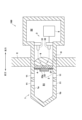
- FIG. 1 is a cross-sectional view showing a hydrogen detection device in one embodiment of the present invention.
- FIG. 11 is a cross-sectional view showing a hydrogen detection device according to another embodiment of the present invention.
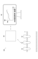
- FIG. 13 is a schematic diagram showing a hydrogen anomaly detection system according to another embodiment.
- the hydrogen detection device 100 in this embodiment is attached to a chamber in which hydrogen is burned, such as by mixing hydrogen with a fuel such as natural gas and burning it, or by burning hydrogen itself, and detects hydrogen in the chamber.
- the chamber referred to here is a crankcase C of an internal combustion engine that burns hydrogen, but is not limited to the crankcase C and may be a housing of an external combustion engine such as a gas turbine.
- the hydrogen detection device 100 is assumed to be used in an internal combustion engine for a ship, but may be used in any internal combustion engine that burns hydrogen and/or an external combustion engine that burns hydrogen, and may be used in any mobile body such as an aircraft or an automobile (e.g., a hydrogen combustion vehicle and/or a fuel cell vehicle).
- the hydrogen detection device 100 may be used to detect hydrogen generated in a combustion engine, a fuel cell, and/or a water electrolysis device used in a combustion furnace or a power plant, etc., other than the crankcase C.
- the hydrogen detection device 100 may be attached to a pipe other than the crankcase C.
- the piping refers to an exhaust pipe, such as a flue, through which gas accompanying the combustion of hydrogen flows, or a piping through which process gas generated in a process for producing hydrogen flows, or other piping through which gas containing hydrogen flows.
- exhaust pipe such as a flue
- piping through which process gas generated in a process for producing hydrogen flows
- gas containing hydrogen flows or other piping through which gas containing hydrogen flows.
- forward refers to the direction toward the inside of the crankcase C
- rearward refers to the direction opposite to the direction toward the inside of the crankcase C.
- the hydrogen detection device 100 is inserted into the crankcase C and comprises a casing 1 having an internal space into which gas can be introduced, a physical quantity change unit 2 provided in the internal space of the casing 1 and whose physical quantity changes according to the concentration of hydrogen, a physical quantity detection unit 3 provided in the internal space of the casing 1 and which detects the physical quantity in the physical quantity change unit 2, a protective film 4 that protects the physical quantity change unit 2, a calculation unit 5 that calculates the hydrogen concentration based on the physical quantity detected by the physical quantity detection unit 3, and an isolation member 6 that isolates the internal space of the casing 1 into a first space S1 and a second space S2.
- the configuration of each unit will be described below.
- the casing 1 houses the physical quantity change unit 2 and the physical quantity detection unit 3. Specifically, the casing 1 is roughly cylindrical, and the physical quantity change unit 2 and the physical quantity detection unit 3 are provided in the internal space formed by the cylindrical shape.
- the casing 1 also has an inlet/outlet port 11 for introducing or discharging the hydrogen-containing gas in the crankcase C into the internal space of the casing 1.
- the inlet/outlet port 11 actively introduces the hydrogen-containing gas in the crankcase C into the internal space of the casing 1, while suppressing the introduction of liquids, such as oil, in the crankcase C into the internal space of the casing 1. Since the molecular weight of hydrogen is smaller than that of other gases, it is preferable that at least one inlet/outlet port 11 is arranged so as to open downward into the crankcase C in order to actively introduce hydrogen into the internal space of the casing 1. Note that, although multiple inlet/outlet ports 11 are provided in this embodiment, the number and size of the inlet/outlet ports 11 are not particularly limited.
- the physical quantity change section 2 includes an alloy member 21 whose light transmittance changes depending on the concentration of hydrogen.
- the alloy member 21 is, for example, a gasochromic metal thin film.
- the gasochromic metal thin film is formed by incorporating hydrogen into a metal belonging to the platinum group (e.g., palladium, etc.). When the gasochromic metal thin film comes into contact with a gas containing hydrogen, the light transmittance of the gasochromic metal thin film changes reversibly.
- the physical quantity detection unit 3 detects changes in the intensity of light transmitted through the alloy member 21.
- the physical quantity detection unit 3 includes a light irradiation unit 31 that irradiates the alloy member 21 with light, and a light detection unit 32 that detects the light transmitted through the alloy member 21.
- the light irradiation unit 31 is, for example, a light emitting diode.
- the irradiation surface of the light irradiation unit 31 is arranged facing the alloy member 21.
- the light irradiation unit 31 is not limited to a light emitting diode, and may be, for example, another light irradiation element such as a laser diode.
- the light detection unit 32 is, for example, a photodiode.
- the detection surface of the light detection unit 32 is arranged facing the alloy member 21.
- the light detection unit 32 is not limited to a photodiode, and may be, for example, another light detection element such as a CCD camera.
- the physical quantity change unit 2 further includes a reflecting member 22 having a reflecting surface 22a that reflects the light irradiated from the light irradiating unit 31 to the light detecting unit 32.
- the reflecting member 22 is, for example, a reflecting mirror having a thin plate shape, and is disposed with the reflecting surface 22a facing the light irradiating unit 31 and the light detecting unit 32.
- the reflecting member 22 is provided in front of the alloy member 21.
- the alloy member 21 is provided on the optical path from the light irradiating unit 31 to the light detecting unit 32 via the reflecting member 22.
- the area of the reflecting surface 22a is configured to be smaller than the area of the face of the alloy member 21 facing the reflecting member 22.
- the protective film 4 allows hydrogen to pass through the alloy member 21, and protects the alloy member 21 from inhibitors that inhibit changes in light transmittance in the alloy member 21, such as oil, soot, or smoke generated in the crankcase C.
- the protective film 4 protects the alloy member 21 from inhibitors means that inhibitors such as oil, soot, or smoke do not adhere to the alloy member 21, or that the inhibitors do not adhere to the protective film 4 due to flowing under their own weight, etc., so that changes in light transmittance in the alloy member 21 are not inhibited.
- the protective film 4 is silicon that is resistant to oil and permeable to hydrogen.
- the protective film 4 is translucent. The protective film 4 covers the entire portion of the surface of the alloy member 21 that faces the reflecting surface 22a that is not in contact with the reflecting surface 22a, but may cover only a portion that is not in contact with the reflecting surface 22a.
- the calculation unit 5 is a general-purpose or dedicated computer equipped with a CPU, memory, etc. Specifically, the calculation unit 5 is electrically connected to the light detection unit 32, and the CPU and its peripheral devices work together in accordance with a program stored in a specified area of the memory to calculate the hydrogen concentration based on the light intensity signal obtained by the light detection unit 32.
- the hydrogen concentration calculated by the calculation unit 5 is displayed on a display unit, such as a display.
- the calculation unit 5 may store a predetermined threshold value and compare the calculated hydrogen concentration with the threshold value. The calculation unit 5 may then output a hydrogen concentration abnormality signal indicating an abnormality in the hydrogen concentration when the calculated hydrogen concentration exceeds the threshold value.
- a display unit such as a display may display characters or figures indicating an abnormality in the hydrogen concentration, or the hydrogen detection device 100 may emit an alarm sound indicating an abnormality in the hydrogen concentration. Note that the configuration in which the calculation unit 5 compares the calculated hydrogen concentration with the predetermined threshold value and outputs the hydrogen concentration abnormality signal is not a required configuration.
- the isolation member 6 isolates the internal space of the casing 1 into a first space S1 into which gas is introduced and in which the physical quantity change unit 2 is housed, and a second space S2 into which the introduction of gas is blocked and in which the physical quantity detection unit 3 is housed.
- the isolation member 6 is, for example, a condenser lens made of a light-transmitting material.
- the outer peripheral surface of the condenser lens constituting the isolation member 6 is arranged in airtight contact with the inner peripheral surface 1a of the casing 1 rearward of the inner peripheral surface 1a where the inlet/outlet port 11 is provided, thereby blocking the introduction of gas into the second space S2.
- the first space S1 is connected to the inlet/outlet port 11, and when the casing 1 is inserted into the crankcase C, gas containing hydrogen in the crankcase C is introduced into the first space S1.
- the alloy member 21, the reflective member 22, and the protective film 4 are housed in the first space S1. Furthermore, when the casing 1 is inserted into the crankcase C, the alloy member 21, the protective film 4, and the reflective member 22 are arranged in this order in order of proximity to the wall that constitutes the crankcase C.
- the second space S2 is located behind the first space S1 via the isolating member 6.
- the second space S2 houses the light irradiation unit 31, the light detection unit 32, and the calculation unit 5.
- the alloy member 21 is supported in contact with the reflecting surface 22a. Specifically, the alloy member 21 is deposited on the surface of the isolating member 6 facing the first space S1, so that in the first space S1, the surface of the alloy member 21 in contact with the surface of the isolating member 6 faces the light irradiation unit 31 and the light detection unit 32, and the surface of the alloy member 21 on the opposite side is disposed in contact with the reflecting surface 22a. Note that, in this embodiment, the alloy member 21 is deposited on the entire surface of the isolating member 6 facing the first space S1, but it may also be deposited on a portion of the surface of the isolating member 6 facing the first space S1.
- the hydrogen detection device 100 is attached to the mounting hole H provided in the wall of the crankcase C.
- the light transmittance of the alloy member 21 changes according to the concentration of hydrogen contained in the gas. Then, the light irradiated from the light irradiating unit 31 passes through the isolation member 6 and passes through the alloy member 21 according to the light transmittance that changes according to the concentration of hydrogen.
- the light that passes through the alloy member 21 is reflected by the reflecting surface 22a and passes through the alloy member 21 again.
- the light then passes through the isolation member 6 again and is detected by the light detection unit 32.
- the calculation unit 5 calculates the hydrogen concentration in the crankcase C.
- the calculated hydrogen concentration is displayed on a display unit such as a display (see attached figure).
- a casing 1 is inserted into a crankcase C associated with hydrogen combustion, and a physical quantity change unit 2 and a physical quantity detection unit 3 are provided in the internal space of the casing 1, thereby making it possible to detect hydrogen in the crankcase C associated with hydrogen combustion.
- the internal space of the crankcase C is separated by an isolating member 6 into a first space S1 and a second space S2, with the first space S1 receiving gas and housing the physical quantity change unit 2, and the second space S2 blocking the introduction of gas and housing the physical quantity detection unit 3, so that the physical quantity detection unit 3 is separated from the first space S1 receiving gas. Therefore, the physical quantity detection unit 3 is not contaminated by, for example, oil, soot, or smoke inside the crankcase C, and the physical quantity detection unit 3 can accurately detect changes in the physical quantity in the physical quantity change unit 2.
- the light irradiation unit 31 and the light detection unit 32 housed in the second space S2 are isolated from the first space S1 by the isolation member 6, so the light irradiation unit 31 and the light detection unit 32 are not contaminated by, for example, oil, soot, or smoke inside the crankcase C.
- the amount of light that the light irradiation unit 31 irradiates onto the alloy member 21 and the amount of light that the light detection unit 32 detects after passing through the alloy member 21 are less likely to fluctuate, allowing hydrogen to be detected accurately.
- both the light emitting unit 31 and the light detecting unit 32 are provided in positions facing the reflecting surface 22a. Therefore, the casing 1 can be made smaller than when the reflecting member 22 is not provided.
- the area of the reflecting surface 22a is configured to be smaller than the area of the surface of the alloy member 21 that faces the reflecting member 22, so that even when the reflecting member 22 is provided, the permeation of hydrogen into the alloy member 21 is not impeded, and hydrogen can be permeated into the alloy member 21.
- the alloy member 21 is vapor-deposited onto the isolation member 6, so that the alloy member 21 contacts the reflective surface 22a while being supported by the isolation member 6, making it possible to eliminate the need for a substrate between the alloy member 21 and the reflective member 22 to support the alloy member 21 on the reflective member 22.
- the alloy member 21 is covered with the protective film 4, the surface of the alloy member 21 is not contaminated with, for example, oil, soot, or smoke in the crankcase or piping.
- the protective film 4 allows hydrogen to pass through, even when the alloy member 21 is covered with the protective film 4, the light transmittance of the alloy member 21 is not inhibited from changing in response to the hydrogen concentration, and the physical quantity detection unit 3 can accurately detect hydrogen.
- the alloy member 21 is vapor-deposited on the isolating member 6, which eliminates the need for a support member for supporting the alloy member 21 on the reflecting member 22, but such a support member may also be used.
- the physical quantity change unit 2 includes a support member 23 that is disposed between the reflecting member 22 and the alloy member 21 and supports the alloy member 21 on the reflecting member 22.
- the support member 23 is, for example, flat and translucent, and the outer peripheral surface of the support member 23 is arranged so as to be in airtight contact with the inner peripheral surface 1a of the casing 1 in front of the inner peripheral surface 1a where the inlet/outlet port 11 is provided.
- the reflecting member 22 is supported on the front surface of the support member 23, and the alloy member 21 is supported on the rear surface of the support member 23.
- the protective film 4 protects the surface of the alloy member 21 opposite to the surface supported by the support member 23.
- the alloy member 21 and the reflecting member 22 are in contact with the entire surface of the support member 23, but they may be in contact with only a part of the surface of the support member 23.
- the alloy member 21 may be directly attached to the reflecting member 22 without using the support member 23.
- the hydrogen detection device 100 in the above embodiment may be used in a hydrogen concentration abnormality detection system 1000 that detects an abnormality in hydrogen concentration.
- the hydrogen concentration abnormality detection system 1000 includes a plurality of hydrogen detection devices 100 inserted, for example, in a pipe P, a control device 200 that is configured to be able to communicate with the plurality of hydrogen detection devices 100 via wire or wirelessly and that compares the hydrogen concentration detected by the plurality of hydrogen detection devices 100 with a predetermined threshold value to determine an abnormality in hydrogen concentration, and an alarm unit 300 that is configured to be able to communicate with the control device 200 via wire or wirelessly and that notifies a user of the abnormality in hydrogen concentration when the control device 200 determines that there is an abnormality in hydrogen concentration.
- the alarm unit 300 is a display device such as a display, but is not limited to a display device, and the alarm unit 300 may be, for example, a buzzer that emits an alarm sound or a warning light.
- the control device 200 when at least one of the multiple detected hydrogen concentrations exceeds a predetermined threshold, the control device 200 outputs a hydrogen concentration abnormality signal to the notification unit 300, which is a signal indicating an abnormality in the hydrogen concentration.
- the hydrogen concentration abnormality signal is a signal that indicates, in addition to the abnormality in hydrogen concentration, which of the multiple hydrogen detection devices 100 has exceeded the threshold.
- the notification unit 300 receives the hydrogen concentration abnormality signal, it causes characters or a figure indicating the abnormality in hydrogen concentration to be displayed on the display. This allows the user to easily know at which location in the piping P to which the multiple hydrogen detection devices 100 are attached the hydrogen concentration abnormality has occurred. Note that, although multiple hydrogen detection devices 100 are attached to the piping P in FIG. 3, only one hydrogen detection device 100 may be attached.
- the isolating member 6 is a focusing lens made of a light-transmitting material, but the isolating member 6 is not limited to this.
- the isolating member 6 may be any member that separates the internal space of the casing 1 into a first space S1 and a second space S2.
- the alloy member 21 may function as the isolating member 6 by being arranged in airtight contact with the inner peripheral surface 1a of the casing 1 forward of the inner peripheral surface 1a where the inlet/outlet port 11 is provided.
- the physical quantity change unit 2 is configured to include a reflecting member 22, but the physical quantity change unit 2 does not have to include a reflecting member 22.
- the light irradiating unit 31 and the light detecting unit 32 may be arranged opposite each other via the alloy member 21, and the light irradiating unit 31 may be configured to detect the light that is irradiated and transmitted through the alloy member 21 by the light detecting unit 32.
- the protective film 4 is made of silicon, but the protective film 4 is not limited to silicon as long as it allows light and hydrogen to pass through the alloy member 21 and protects the alloy member 21 from oil, soot, smoke, etc. generated in the crankcase C or the piping.
- the protective film 4 may be made of a fluororesin.
- the hydrogen detection device 100 includes a protective film 4 and a calculation unit 5, but these are not essential components for detecting hydrogen contained in the gas generated in the crankcase C.
- the hydrogen detection device 100 only needs to include at least a casing 1, a physical quantity change unit 2, and a physical quantity detection unit 3.
- the light irradiation unit 31, the light detection unit 32, and the calculation unit 5 are housed in the second space S2, but the calculation unit 5 does not have to be housed in the second space S2.
- the calculation unit 5 may be provided outside the casing 1 and electrically connected to the light detection unit 32.
- the present invention provides a hydrogen detection device that detects hydrogen in the environment inside the crankcase or piping of an internal combustion engine.
Landscapes
- Physics & Mathematics (AREA)
- Chemical & Material Sciences (AREA)
- Engineering & Computer Science (AREA)
- Chemical Kinetics & Catalysis (AREA)
- Plasma & Fusion (AREA)
- Health & Medical Sciences (AREA)
- Life Sciences & Earth Sciences (AREA)
- Analytical Chemistry (AREA)
- Biochemistry (AREA)
- General Health & Medical Sciences (AREA)
- General Physics & Mathematics (AREA)
- Immunology (AREA)
- Pathology (AREA)
- Investigating Or Analysing Materials By Optical Means (AREA)
Abstract
チャンバ内又は配管内のガスに含まれる水素を検出する水素検出装置であって、前記チャンバ内又は前記配管内に挿入され、前記ガスが導入可能な内部空間を有するケーシングと、前記内部空間に設けられ、前記水素の濃度に応じて物理量が変化する物理量変化部と、前記内部空間に設けられ、前記物理量変化部における前記物理量を検出する物理量検出部とを備え、前記内部空間は、隔離部材によって第1空間と第2空間とに隔離されており、前記第1空間には、前記ガスが導入されるとともに前記物理量変化部が収容され、前記第2空間には、前記ガスの導入が遮断されるとともに前記物理量検出部が収容される。
Description
本発明は、水素検出装置及び水素検出方法に関するものである。
従来、例えば船舶用内燃機関のクランクケース等といったチャンバ又は配管に取り付けられて、当該チャンバ内又は配管内で発生するオイルミストを検出するオイルミスト検出装置がある。この種のオイルミスト検出装置は、例えば特許文献1に示すように、例えば重油を燃料とする船舶用内燃機関に用いられており、軸受過熱等によってチャンバ内で発生するオイルミストを検出している。
ところで、近年、船舶用内燃機関で発生する温室効果ガス等を削減するために、船舶用内燃機関の燃料として、重油の代わりに天然ガスを用いる場合がある。そして、さらに温室効果ガス等を削減するために、従来の燃料に水素を混ぜて水素及び燃料を燃焼させたり、水素だけを燃焼させるといった、船舶用内燃機関の燃料として水素を用いる研究開発が盛んに行われている。これに伴い、チャンバ内又は配管内において、水素を検出するニーズが高まっているが、これまではチャンバ内又は配管内において水素を検出する水素検出装置がなかった。
そこで、本発明は上述したような問題に鑑みてなされたものであり、チャンバ内又は配管内において水素を検出する水素検出装置を提供することをその主たる課題とするものである。
すなわち、本発明に係る水素検出装置は、チャンバ内又は配管内のガスに含まれる水素を検出する水素検出装置であって、前記チャンバ内又は前記配管内に挿入され、前記ガスが導入可能な内部空間を有するケーシングと、前記内部空間に設けられ、前記水素の濃度に応じて物理量が変化する物理量変化部と、前記内部空間に設けられ、前記物理量変化部における前記物理量を検出する物理量検出部とを備え、前記内部空間は、隔離部材によって第1空間と第2空間とに隔離されており、前記第1空間には、前記ガスが導入されるとともに前記物理量変化部が収容され、前記第2空間には、前記ガスの導入が遮断されるとともに前記物理量検出部が収容されることを特徴とする。
このような水素検出装置であれば、チャンバ内又は配管内にケーシングが挿入され、当該ケーシングの内部空間には、チャンバ内又は配管内の水素の濃度に応じて物理量が変化する物理量変化部及び物理量を検出する物理量検出部が設けられるので、水素燃焼に伴うチャンバ内又は配管内の水素を検出することができる。
また、チャンバの内部空間は、隔離部材によって第1空間と第2空間とに隔離されており、第1空間には、ガスが導入されるとともに物理量変化部が収容され、第2空間には、ガスの導入が遮断されるとともに物理量検出部が収容されるので、物理量検出部は、チャンバ内又は配管内のガスが導入される第1空間から隔離される。従って、物理量検出部は、チャンバ内又は配管内の例えば油、すす又は煙等によって汚れないので、物理量検出部は、物理量変化部における物理量の変化を正確に検出することができる。
また、チャンバの内部空間は、隔離部材によって第1空間と第2空間とに隔離されており、第1空間には、ガスが導入されるとともに物理量変化部が収容され、第2空間には、ガスの導入が遮断されるとともに物理量検出部が収容されるので、物理量検出部は、チャンバ内又は配管内のガスが導入される第1空間から隔離される。従って、物理量検出部は、チャンバ内又は配管内の例えば油、すす又は煙等によって汚れないので、物理量検出部は、物理量変化部における物理量の変化を正確に検出することができる。
前記水素検出装置の具体的態様としては、前記物理量変化部は、前記水素の濃度に応じて光透過率が変化する合金部材を備え、前記物理量検出部は、前記合金部材に光を照射する光照射部と、前記合金部材を透過した光を検出する光検出部とを備えるものが挙げられる。
このような構成であれば、第2空間に収容された光照射部及び光検出部は、隔離部材によって第1空間から隔離されているので、光照射部及び光検出部は、チャンバ内又は配管内の例えば油、すす又は煙等によって汚れない。その結果、光照射部が合金部材に照射する光の量、及び、光検出部が合金部材を透過して検出する光の量が変動しにくくなるので、水素を正確に検出することができる。
合金部材に光を照射して、合金部材を透過した光を検出するための具体的態様としては、前記物理量変化部は、前記第1空間に設けられ、前記光照射部から照射された光を前記光検出部に反射する反射面を有する反射部材をさらに備え、前記合金部材は、前記光照射部から前記反射部材を介して前記光検出部に至るまでの光路上に設けられるものが挙げられる。
このような構成であれば、光照射部から照射された光は、反射部材により光検出部に反射するので、光照射部及び光検出部は、どちらも反射面と同じ側に設けられる。その結果、反射部材を有さない場合と比較して、ケーシングを簡易な構造にすることができる。
反射面が合金部材の面を全て覆ってしまうと、合金部材に水素が透過しないので、合金部材に水素を透過させるためには、前記反射面の面積は、前記反射面に対向する前記合金部材の面の面積よりも小さく構成されることが好ましい。
ここで、従来、反射部材を用いる場合、合金部材は、透光可能な部材で構成されている基板を介して反射部材に支持されていたところ、この基板を不要とするためには、前記合金部材は、前記反射面に接して支持されることが好ましい。
また、他の態様としては、前記合金部材は、透光可能な部材で構成された支持部材を介して前記反射面に支持されるものが挙げられる。
水素と接触することにより光透過率が変化する合金部材の具体的態様として、前記合金部材は、ガスクロミック金属薄膜であることが挙げられる。
前記合金部材は、水素を透過させるとともに、前記チャンバ内又は前記配管内で発生して前記合金部材における光透過率の変化を阻害する阻害物質から前記合金部材を保護する保護膜により覆われているものが好ましい。
このような構成であれば、合金部材は、チャンバ内又は配管内で発生する例えば油、すす又は煙といった、合金部材における光透過率の変化を阻害する阻害物質から合金部材を保護する保護膜により覆われているので、合金部材の表面が当該阻害物質で汚れることを抑制することができる。また、合金部材が保護膜で覆われた状態においても、保護膜は水素を透過させるので、合金部材は水素濃度に応じて光透過率が変化し、物理量検出部が水素を検出することが阻害されない。
水素を透過させるとともに油への耐性を有する保護膜の具体的な構成としては、保護膜は、シリコン又はフッ素樹脂により構成されることが好ましい。
このように構成した本発明によれば、チャンバ内又は配管内において水素を検出する水素検出装置を提供することができる。
以下に、本発明に係る水素検出装置の一実施形態について、図面を参照して説明する。なお、以下に示す何れの図についても、わかりやすくするために、適宜省略し又は誇張して模式的に描かれている場合がある。同一の構成要素については、同一の符号を付して説明を適宜省略する。
<装置構成>
本実施形態における水素検出装置100は、図1に示すように、燃料である例えば天然ガスに水素を混ぜて燃焼させたり、水素そのものを燃焼させたりといった、水素が燃焼しているチャンバに取り付けられ、チャンバ内の水素を検出するものである。ここで言うチャンバとは、水素を燃焼させる内燃機関のクランクケースCであるが、クランクケースCに限られず、例えばガスタービン等といった外燃機関のハウジングであってもよい。なお、本実施形態において、水素検出装置100は船舶用内燃機関に用いられることを想定しているが、水素を燃焼させる内燃機関及び/又は水素を燃焼させる外燃機関に用いられるものであればよく、例えば航空機、自動車(例えば水素燃焼車及び/又は燃料電池車)等の移動体に用いられてもよい。また、移動体に限らず、燃焼炉又は発電所等で用いられる燃焼機関、燃料電池、及び/又は、水電解装置で発生する水素検出に用いられるものであってもよい。また、水素検出装置100は、クランクケースCの他に配管に取り付けられていてもよい。本実施形態において、配管とは、例えば水素の燃焼に伴うガスが流れる例えば煙道といった排気管、又は、水素が生成されるプロセスにおいて発生するプロセスガスが流れる配管その他水素を含むガスが流れる配管である。以下では、前方とは、クランクケースC内に向かう方向を言い、後方とは、クランクケースC内に向かう方向と反対の方向を言う。
本実施形態における水素検出装置100は、図1に示すように、燃料である例えば天然ガスに水素を混ぜて燃焼させたり、水素そのものを燃焼させたりといった、水素が燃焼しているチャンバに取り付けられ、チャンバ内の水素を検出するものである。ここで言うチャンバとは、水素を燃焼させる内燃機関のクランクケースCであるが、クランクケースCに限られず、例えばガスタービン等といった外燃機関のハウジングであってもよい。なお、本実施形態において、水素検出装置100は船舶用内燃機関に用いられることを想定しているが、水素を燃焼させる内燃機関及び/又は水素を燃焼させる外燃機関に用いられるものであればよく、例えば航空機、自動車(例えば水素燃焼車及び/又は燃料電池車)等の移動体に用いられてもよい。また、移動体に限らず、燃焼炉又は発電所等で用いられる燃焼機関、燃料電池、及び/又は、水電解装置で発生する水素検出に用いられるものであってもよい。また、水素検出装置100は、クランクケースCの他に配管に取り付けられていてもよい。本実施形態において、配管とは、例えば水素の燃焼に伴うガスが流れる例えば煙道といった排気管、又は、水素が生成されるプロセスにおいて発生するプロセスガスが流れる配管その他水素を含むガスが流れる配管である。以下では、前方とは、クランクケースC内に向かう方向を言い、後方とは、クランクケースC内に向かう方向と反対の方向を言う。
具体的に水素検出装置100は、クランクケースC内に挿入され、ガスが導入可能な内部空間を有するケーシング1と、ケーシング1の内部空間に設けられ、水素の濃度に応じて物理量が変化する物理量変化部2と、ケーシング1の内部空間に設けられ、物理量変化部2における物理量を検出する物理量検出部3と、物理量変化部2を保護する保護膜4と、物理量検出部3により検出された物理量に基づいて水素濃度を演算する演算部5と、ケーシング1の内部空間を第1空間S1と第2空間S2とに隔離する隔離部材6とを備える。以下、各部の構成について説明する。
ケーシング1は、物理量変化部2及び物理量検出部3を収容するものである。具体的にケーシング1は、概略円筒状をなしており、円筒状により形成された内部空間に物理量変化部2及び物理量検出部3が設けられる。
また、ケーシング1は、クランクケースC内の水素を含むガスをケーシング1の内部空間に導入又は導出する導出入ポート11を有する。本実施形態において、導出入ポート11は、クランクケースC内の水素を含むガスを積極的にケーシング1の内部空間に導入するとともに、クランクケースC内の例えば油といった液体がケーシング1の内部空間に導入されるのを抑制するものである。水素の分子量は他の気体と比較して小さいので、ケーシング1の内部空間に水素を積極的に導入するために、少なくとも1つの導出入ポート11は、クランクケースCの下方に向けて開口するように配置されていることが好ましい。なお、本実施形態では複数の導出入ポート11が設けられるが、導出入ポート11の数及び大きさは特に限定されない。
物理量変化部2は、水素の濃度に応じて光透過率が変化する合金部材21を備える。本実施形態において、合金部材21は、例えばガスクロミック金属薄膜である。ガスクロミック金属薄膜は、白金族に属する金属(例えばパラジウム等)に水素を含有させることにより構成されるものである。ガスクロミック金属薄膜が水素を含むガスと接触すると、ガスクロミック金属薄膜の光透過率は可逆的に変化する。
物理量検出部3は、合金部材21を透過した光強度の変化を検出するものである。具体的に物理量検出部3は、合金部材21に光を照射する光照射部31と、合金部材21を透過した光を検出する光検出部32とを備える。
光照射部31は、例えば発光ダイオードである。光照射部31の照射面は、合金部材21に向けて配置される。なお、光照射部31は、発光ダイオードに限られず、例えばレーザダイオード等の他の光照射素子であってもよい。
光検出部32は、例えばフォトダイオードである。光検出部32の検出面は、合金部材21に向けて配置される。なお、光検出部32は、フォトダイオードに限られず、例えばCCDカメラ等の他の光検出素子であってもよい。
本実施形態では、物理量変化部2は、光照射部31から照射された光を光検出部32に反射する反射面22aを有する反射部材22をさらに備える。反射部材22は、薄板状をなす例えば反射ミラーであり、反射面22aを光照射部31及び光検出部32に向けて配置される。本実施形態では、反射部材22は、合金部材21よりも前方に設けられる。これにより、合金部材21は、光照射部31から反射部材22を介して光検出部32に至るまでの光路上に設けられる。また、反射面22aの面積は、反射部材22に対向する合金部材21の面の面積よりも小さく構成される。
保護膜4は、合金部材21に水素を透過させるとともに、クランクケースC内で発生した油、すす又は煙等といった、合金部材21における光透過率の変化を阻害する阻害物質から合金部材21を保護するものである。本実施形態において、「保護膜4が阻害物質から合金部材21を保護する」とは、油、すす又は煙といった阻害物質が合金部材21に付着しないことにより、又は、阻害物質が自重で流れること等で保護膜4に付着した状態とならないことにより、合金部材21における光透過率の変化が阻害されないことを言う。具体的に保護膜4は、油への耐性及び水素透過性を有するシリコンである。また、本実施形態において、保護膜4は、透光性を有する。なお、保護膜4は、反射面22aを向く合金部材21の面のうち、反射面22aに接していない部分全体を覆っているが、反射面22aに接していない一部分を覆うものであってもよい。
演算部5は、CPU、メモリなどを備えた汎用乃至専用のコンピュータである。具体的に演算部5は、光検出部32と電気的に接続されており、メモリの所定領域に格納したプログラムに従ってCPUやその周辺機器が協働することによって、光検出部32により得られた光強度信号に基づいて、水素濃度を演算するものである。なお、演算部5により演算された水素濃度は、例えばディスプレイといった表示部に表示される。
本実施形態において、演算部5は、所定の閾値を格納しており、演算した水素濃度と当該閾値とを比較するものであってもよい。そして、演算部5は、演算した水素濃度が閾値を超えた場合に、水素濃度の異常を示す水素濃度異常信号を出力してもよい。水素濃度異常信号が出力されると、例えばディスプレイといった表示部に水素濃度の異常を示す文字又は図が表示されたり、水素濃度の異常を示す警報音が水素検出装置100から発生してもよい。なお、演算部5が所定の閾値と演算した水素濃度とを比較して、水素濃度異常信号を出力する構成は、必須の構成ではない。
隔離部材6は、ガスが導入されるとともに物理量変化部2が収容される第1空間S1とガスの導入が遮断されるとともに物理量検出部3が収容される第2空間S2とにケーシング1の内部空間を隔離するものである。具体的に隔離部材6は、透光可能な部材で構成されている例えば集光レンズである。本実施形態では、ケーシング1の内部空間において、隔離部材6をなす集光レンズの外側周面が、導出入ポート11が設けられたケーシング1の内側周面1aよりも後方の内側周面1aに気密に接触するように配置されることによって、第2空間S2へのガスの導入が遮断される。
第1空間S1は、導出入ポート11に接続されており、ケーシング1がクランクケースC内に挿入された状態において、第1空間S1には、クランクケースC内の水素を含むガスが導入される。本実施形態において、合金部材21、反射部材22及び保護膜4が第1空間S1に収容されている。また、ケーシング1がクランクケースC内に挿入された状態において、クランクケースCを構成する壁に近い順に、合金部材21、保護膜4及び反射部材22がこの順に配置されている。
第2空間S2は、隔離部材6を介して第1空間S1よりも後方に位置している。本実施形態において、第2空間S2には、光照射部31、光検出部32及び演算部5が収容されている。
また、本実施形態では、合金部材21は、反射面22aに接して支持される。具体的に合金部材21は、第1空間S1に面する隔離部材6の表面に蒸着されることにより、第1空間S1内において、隔離部材6の表面に接する合金部材21の面が光照射部31及び光検出部32に向けて配置され、その反対側の合金部材21の面が反射面22aに接して配置される。なお、本実施形態では、合金部材21は、第1空間S1に面する隔離部材6の全面に蒸着されるが、第1空間S1に面する隔離部材6の面の一部分に蒸着されていてもよい。
<水素検出装置100を用いた水素検出方法>
次に本実施形態における水素検出装置100を用いた水素検出方法について説明する。
次に本実施形態における水素検出装置100を用いた水素検出方法について説明する。
クランクケースCの壁に設けられた取付孔Hに水素検出装置100を取り付ける。
導出入ポート11がクランクケースC内に配置された状態において、第1空間S1には、クランクケースC内の水素を含むガスが導入される。一方、第2空間S2は、隔離部材6により第1空間S1から隔離されているので、第2空間S2では、クランクケースC内のガスの導入が遮断される。
水素を含むガスが合金部材21に接すると、ガスに含まれる水素の濃度に応じて、合金部材21の光透過率が変化する。そして、光照射部31から照射された光は、隔離部材6を介して、水素の濃度に応じて変化した光透過率に応じて合金部材21を透過する。
合金部材21を透過した光は、反射面22aで反射されて、再び合金部材21を透過する。その後、光は、再び隔離部材6を透過して、光検出部32により検出される。
光検出部32が検出した光強度信号に基づいて、演算部5はクランクケースC内の水素濃度を演算する。演算された水素濃度は、例えばディスプレイといった表示部(付図示)に表示される。
<本実施形態の効果>
本実施形態における水素検出装置100によれば、水素燃焼に伴うクランクケースC内にケーシング1が挿入され、ケーシング1の内部空間には、物理量変化部2及び物理量検出部3が設けられるので、水素燃焼に伴うクランクケースC内の水素を検出することができる。
本実施形態における水素検出装置100によれば、水素燃焼に伴うクランクケースC内にケーシング1が挿入され、ケーシング1の内部空間には、物理量変化部2及び物理量検出部3が設けられるので、水素燃焼に伴うクランクケースC内の水素を検出することができる。
また、クランクケースCの内部空間は、隔離部材6によって第1空間S1と第2空間S2とに隔離されており、第1空間S1には、ガスが導入されるとともに物理量変化部2が収容され、第2空間S2には、ガスの導入が遮断されるとともに物理量検出部3が収容されるので、物理量検出部3は、ガスが導入される第1空間S1から隔離される。従って、物理量検出部3は、クランクケースC内の例えば油、すす又は煙等によって汚れないので、物理量検出部3は、物理量変化部2における物理量の変化を正確に検出することができる。
具体的には、第2空間S2に収容された光照射部31及び光検出部32は、隔離部材6によって第1空間S1から隔離されているので、光照射部31及び光検出部32は、クランクケースC内の例えば油、すす又は煙等によって汚れない。その結果、光照射部31が合金部材21に照射する光の量、及び、光検出部32が合金部材21を透過して検出する光の量が変動しにくくなるので、水素を正確に検出することができる。
また、光照射部31から照射された光は、反射部材22により光検出部32に反射されるので、光照射部31及び光検出部32は、どちらも反射面22aに対向する位置に設けられる。従って、反射部材22を有さない場合と比較して、ケーシング1を小型にすることができる。
その上、反射面22aの面積は、反射部材22に対向する合金部材21の面の面積よりも小さく構成されるので、反射部材22を設けた場合であっても合金部材21への水素の透過が阻害されず、合金部材21に水素を透過させることができる。
さらに、本実施形態では、合金部材21が隔離部材6に蒸着されることにより、合金部材21が隔離部材6に支持された状態で反射面22aに接するので、合金部材21を反射部材22に支持するために合金部材21及び反射部材22に介在する基板を不要にすることができる。
その上、合金部材21は、保護膜4により覆われているので、合金部材21の表面が、クランクケース内又は配管内の例えば油、すす又は煙等で汚れない。また、保護膜4は水素を透過させるので、合金部材21が保護膜4で覆われた状態においても、合金部材21が水素濃度に応じて光透過率が変化することが阻害されず、物理量検出部3は水素を正確に検出することができる。
<その他の実施形態>
なお、本発明は、前記実施形態に限られるものではない。
なお、本発明は、前記実施形態に限られるものではない。
前記実施形態において、合金部材21が隔離部材6に蒸着されることにより、合金部材21を反射部材22に支持する支持部材が不要となったが、当該支持部材を用いる構成としてもよい。例えば、図2に示すように、物理量変化部2は、反射部材22及び合金部材21に介在して設けられ、合金部材21を反射部材22に支持する支持部材23を備えるものが挙げられる。
具体的に支持部材23は、例えば平板状をなすとともに透光性を有するものであり、支持部材23の外側周面は、導出入ポート11が設けられたケーシング1の内側周面1aよりも前方の内側周面1aに気密に接触するように配置される。そして、ケーシング1の軸方向において、反射部材22は支持部材23の前方の面に支持され、合金部材21は支持部材23の後方の面に支持される。また、保護膜4は、支持部材23に支持される合金部材21の面と反対側の面を保護する。なお、図2において、合金部材21及び反射部材22は、支持部材23の面全体に接するものであるが、支持部材23の面の一部に接するものであってもよい。また、図2において、支持部材23を用いずに、合金部材21が反射部材22に直接取り付けられるものであってもよい。
さらに、前記実施形態における水素検出装置100は、水素濃度の異常を検知する水素濃度異常検知システム1000に用いられてもよい。具体的には、図3に示すように、水素濃度異常検知システム1000は、例えば配管P内に挿入された複数の水素検出装置100と、複数の水素検出装置100と有線又は無線で通信可能に構成され、複数の水素検出装置100が検出した水素濃度と所定の閾値を比較して水素濃度の異常を判断する制御装置200と、制御装置200と有線又は無線で通信可能に構成され、制御装置200が水素濃度の異常と判断した場合に水素濃度の異常をユーザに知らせる報知部300とを備える。なお、図3において、報知部300は、例えばディスプレイといった表示装置であるが表示装置に限られず、報知部300は、例えば警告音を発するブザー又は警告灯であってもよい。
ここで、制御装置200は、検出された複数の水素濃度のうち、少なくとも一つの水素濃度が所定の閾値を超えた場合に、水素濃度の異常を示す信号である水素濃度異常信号を報知部300に出力する。ここでは、水素濃度異常信号は、水素濃度の異常に加えて、複数の水素検出装置100のうちのどの水素検出装置100で閾値を超えたかを示す信号である。報知部300は、水素濃度異常信号を受け付けると、ディスプレイ上に水素濃度の異常を示す文字又は図をディスプレイに表示させる。これにより、ユーザは、複数の水素検出装置100が取り付けられた配管P内のどの箇所で水素濃度の異常が生じているかを簡単に知ることができる。なお、図3において、配管Pには、複数の水素検出装置100が取り付けられていたが、1つの水素検出装置100が取り付けられていてもよい。
前記実施形態において、隔離部材6は、透光可能な部材で構成されている集光レンズであったが、隔離部材6はこれに限られない。隔離部材6は、ケーシング1の内部空間を第1空間S1と第2空間S2とに隔離するものであればよい。例えば、合金部材21が、導出入ポート11が設けられたケーシング1の内側周面1aよりも前方の内側周面1aに気密に接触するように配置されることによって、隔離部材6としての機能を発揮してもよい。
前記実施形態において、物理量変化部2は、反射部材22を備える構成であったが、物理量変化部2は、反射部材22を備えなくてもよい。具体的には、光照射部31及び光検出部32が合金部材21を介して互いに対向して設けられており、光照射部31が照射して合金部材21を透過した光を光検出部32が検出する構成であってもよい。
前記実施形態において、保護膜4はシリコンで構成されるものであったが、保護膜4は、合金部材21に光及び水素を透過させるとともに、クランクケースC内又は配管内で発生した油、すす又は煙等から合金部材21を保護するものであれば、シリコンに限られない。例えば保護膜4は、フッ素樹脂により構成されていてもよい。
前記実施形態において、水素検出装置100は、保護膜4及び演算部5を備えるものであったが、クランクケースC内で発生するガスに含まれる水素を検出するためには、これらは必須の構成ではない。すなわち、水素検出装置100は、ケーシング1と、物理量変化部2と、物理量検出部3とを少なくとも備えていればよい。
また、前記実施形態において、第2空間S2には、光照射部31、光検出部32及び演算部5が収容されていたが、演算部5は、第2空間S2に収容されていなくてもよい。例えば、演算部5は、ケーシング1の外部に設けられて、光検出部32と電気的に接続されていてもよい。
その他、本発明の趣旨に反しない限りにおいて様々な実施形態の変形や組み合わせを行っても構わない。
本発明によれば、内燃機関のクランクケース内又は配管内の環境において水素を検出する水素検出装置を提供することができる。
100 ・・・水素検出装置
1 ・・・ケーシング
2 ・・・物理量変化部
21 ・・・合金部材
22 ・・・反射部材
22a ・・・反射面
23 ・・・支持部材
3 ・・・物理量検出部
31 ・・・光照射部
32 ・・・光検出部
4 ・・・保護膜
5 ・・・演算部
6 ・・・隔離部材
200 ・・・制御装置
300 ・・・報知部
1000・・・水素濃度異常検知システム
C ・・・クランクケース
S1 ・・・第1空間
S2 ・・・第2空間
1 ・・・ケーシング
2 ・・・物理量変化部
21 ・・・合金部材
22 ・・・反射部材
22a ・・・反射面
23 ・・・支持部材
3 ・・・物理量検出部
31 ・・・光照射部
32 ・・・光検出部
4 ・・・保護膜
5 ・・・演算部
6 ・・・隔離部材
200 ・・・制御装置
300 ・・・報知部
1000・・・水素濃度異常検知システム
C ・・・クランクケース
S1 ・・・第1空間
S2 ・・・第2空間
Claims (10)
- チャンバ内又は配管内のガスに含まれる水素を検出する水素検出装置であって、
前記チャンバ内又は前記配管内に挿入され、前記ガスが導入可能な内部空間を有するケーシングと、
前記内部空間に設けられ、前記水素の濃度に応じて物理量が変化する物理量変化部と、
前記内部空間に設けられ、前記物理量変化部における前記物理量を検出する物理量検出部とを備え、
前記内部空間は、隔離部材によって第1空間と第2空間とに隔離されており、
前記第1空間には、前記ガスが導入されるとともに前記物理量変化部が収容され、
前記第2空間には、前記ガスの導入が遮断されるとともに前記物理量検出部が収容される、水素検出装置。 - 前記物理量変化部は、前記水素の濃度に応じて光透過率が変化する合金部材を備え、
前記物理量検出部は、
前記合金部材に光を照射する光照射部と、
前記合金部材を透過した光を検出する光検出部とを備える、請求項1に記載の水素検出装置。 - 前記物理量変化部は、前記第1空間に設けられ、前記光照射部から照射された光を前記光検出部に反射する反射面を有する反射部材をさらに備え、
前記合金部材は、前記光照射部から前記反射部材を介して前記光検出部に至るまでの光路上に設けられる、請求項2に記載の水素検出装置。 - 前記反射面の面積は、前記反射面に対向する前記合金部材の面の面積よりも小さく構成される、請求項3に記載の水素検出装置。
- 前記合金部材は、前記反射面に接して支持される、請求項3又は4に記載の水素検出装置。
- 前記合金部材は、透光可能な部材で構成された支持部材を介して前記反射面に支持される、請求項2乃至4の何れか一項に記載の水素検出装置。
- 前記合金部材は、ガスクロミック金属薄膜である、請求項2乃至6の何れか一項に記載の水素検出装置。
- 前記合金部材は、前記水素を透過させるとともに、前記チャンバ内又は前記配管内で発生して前記合金部材における光透過率の変化を阻害する阻害物質から前記合金部材を保護する保護膜により覆われている、請求項2乃至7の何れか一項に記載の水素検出装置。
- 前記保護膜はシリコン又はフッ素樹脂で構成される、請求項8に記載の水素検出装置。
- 請求項1に記載の水素検出装置を用いて、チャンバ内又は配管内のガスに含まれる水素を検出する水素検出方法。
Applications Claiming Priority (2)
| Application Number | Priority Date | Filing Date | Title |
|---|---|---|---|
| JP2023-189221 | 2023-11-06 | ||
| JP2023189221 | 2023-11-06 |
Publications (1)
| Publication Number | Publication Date |
|---|---|
| WO2025100115A1 true WO2025100115A1 (ja) | 2025-05-15 |
Family
ID=95695121
Family Applications (1)
| Application Number | Title | Priority Date | Filing Date |
|---|---|---|---|
| PCT/JP2024/033736 Pending WO2025100115A1 (ja) | 2023-11-06 | 2024-09-20 | 水素検出装置及び水素検出方法 |
Country Status (1)
| Country | Link |
|---|---|
| WO (1) | WO2025100115A1 (ja) |
Citations (3)
| Publication number | Priority date | Publication date | Assignee | Title |
|---|---|---|---|---|
| JP2000304732A (ja) * | 1999-02-15 | 2000-11-02 | Ngk Spark Plug Co Ltd | ガス濃度センサ |
| JP2008157648A (ja) * | 2006-12-21 | 2008-07-10 | Horiba Ltd | オイルミスト検出装置 |
| JP2009109504A (ja) * | 2001-07-16 | 2009-05-21 | Sensor Tech Inc | 気相物質の定性および定量分析のためのセンサ装置および方法 |
-
2024
- 2024-09-20 WO PCT/JP2024/033736 patent/WO2025100115A1/ja active Pending
Patent Citations (3)
| Publication number | Priority date | Publication date | Assignee | Title |
|---|---|---|---|---|
| JP2000304732A (ja) * | 1999-02-15 | 2000-11-02 | Ngk Spark Plug Co Ltd | ガス濃度センサ |
| JP2009109504A (ja) * | 2001-07-16 | 2009-05-21 | Sensor Tech Inc | 気相物質の定性および定量分析のためのセンサ装置および方法 |
| JP2008157648A (ja) * | 2006-12-21 | 2008-07-10 | Horiba Ltd | オイルミスト検出装置 |
Similar Documents
| Publication | Publication Date | Title |
|---|---|---|
| EP1936358B1 (en) | Oil mist detector | |
| CN110621980B (zh) | 气体测量系统 | |
| US10458900B2 (en) | Gas detector with normalized response and improved sensitivity | |
| US8692997B2 (en) | Optical gas and/or particulate sensors | |
| CS90191A3 (en) | Fire detector | |
| US12590893B2 (en) | Forward and back scattering smoke detector and method of use | |
| NO20050310L (no) | Brannvarsler | |
| US20080116378A1 (en) | Long-term stable optical sensor arrangement, especially a hydrogen sensor, and combined gas sensor arrangement | |
| WO2022105900A1 (zh) | 一种检测装置 | |
| JP2016176778A (ja) | 光学式水素ガス検知装置及び方法 | |
| WO2025100115A1 (ja) | 水素検出装置及び水素検出方法 | |
| CN209387621U (zh) | 一种环境探测装置 | |
| US6696939B2 (en) | Signaling fire detector | |
| WO2010118749A1 (en) | Gas sensor with filtering sight glass | |
| ES2558837T3 (es) | Dispositivo y procedimiento de medida de la opacidad y de los óxidos de nitrógeno en los gases de escape | |
| WO2014097019A1 (es) | Dispositivo inteligente de rutas de evacuación | |
| CN108169150A (zh) | 一种固体火箭推进剂挥发气体光纤无损在线监测装置 | |
| JP6820731B2 (ja) | ガス検知装置 | |
| NO300346B1 (no) | Foto-akustisk måleanordning | |
| JP2009074899A (ja) | 防爆型ガスセンサ | |
| CN222913489U (zh) | 一种点式激光烟气复合探测器 | |
| JP6912358B2 (ja) | ガス検知器 | |
| JP2011112636A (ja) | 検出装置 | |
| KR20120114500A (ko) | 광투과흡수식 오일 미스트 검출장치 | |
| CN120195118A (zh) | 气体检测装置 |
Legal Events
| Date | Code | Title | Description |
|---|---|---|---|
| 121 | Ep: the epo has been informed by wipo that ep was designated in this application |
Ref document number: 24888415 Country of ref document: EP Kind code of ref document: A1 |
|
| ENP | Entry into the national phase |
Ref document number: 2025556247 Country of ref document: JP Kind code of ref document: A |
|
| WWE | Wipo information: entry into national phase |
Ref document number: 2025556247 Country of ref document: JP |