WO2025100014A1 - 通信方法、検査方法およびデータ共有システム - Google Patents
通信方法、検査方法およびデータ共有システム Download PDFInfo
- Publication number
- WO2025100014A1 WO2025100014A1 PCT/JP2024/027791 JP2024027791W WO2025100014A1 WO 2025100014 A1 WO2025100014 A1 WO 2025100014A1 JP 2024027791 W JP2024027791 W JP 2024027791W WO 2025100014 A1 WO2025100014 A1 WO 2025100014A1
- Authority
- WO
- WIPO (PCT)
- Prior art keywords
- data
- environment
- file name
- shared memory
- stored
- Prior art date
- Legal status (The legal status is an assumption and is not a legal conclusion. Google has not performed a legal analysis and makes no representation as to the accuracy of the status listed.)
- Pending
Links
Images


Classifications
-
- G—PHYSICS
- G06—COMPUTING OR CALCULATING; COUNTING
- G06F—ELECTRIC DIGITAL DATA PROCESSING
- G06F21/00—Security arrangements for protecting computers, components thereof, programs or data against unauthorised activity
- G06F21/50—Monitoring users, programs or devices to maintain the integrity of platforms, e.g. of processors, firmware or operating systems
- G06F21/55—Detecting local intrusion or implementing counter-measures
- G06F21/56—Computer malware detection or handling, e.g. anti-virus arrangements
-
- G—PHYSICS
- G06—COMPUTING OR CALCULATING; COUNTING
- G06F—ELECTRIC DIGITAL DATA PROCESSING
- G06F21/00—Security arrangements for protecting computers, components thereof, programs or data against unauthorised activity
- G06F21/60—Protecting data
- G06F21/64—Protecting data integrity, e.g. using checksums, certificates or signatures
-
- G—PHYSICS
- G06—COMPUTING OR CALCULATING; COUNTING
- G06F—ELECTRIC DIGITAL DATA PROCESSING
- G06F21/00—Security arrangements for protecting computers, components thereof, programs or data against unauthorised activity
- G06F21/70—Protecting specific internal or peripheral components, in which the protection of a component leads to protection of the entire computer
- G06F21/71—Protecting specific internal or peripheral components, in which the protection of a component leads to protection of the entire computer to assure secure computing or processing of information
- G06F21/74—Protecting specific internal or peripheral components, in which the protection of a component leads to protection of the entire computer to assure secure computing or processing of information operating in dual or compartmented mode, i.e. at least one secure mode
Definitions
- the present invention relates to a communication method, an inspection method, and a data sharing system.
- the present invention relates to a communication method that can be suitably used when transmitting generated data to a data storage device that stores the data.
- PCs Personal Computers
- OS operating systems
- these PCs are usually not able to connect to information networks, which creates the problem that the data they generate cannot be easily used.
- a data sharing device is sometimes used in which a PC is connected to an information network, and the generated data is inspected before being passed on to a higher-level server, etc., allowing the generated data to be utilized while maintaining security.
- Patent Document 1 discloses a data sharing device that includes a first environment having a first communication port, a second environment having a second communication port and operating independently of the first environment, and a shared memory accessible from both the first and second environments.
- the first environment includes a data receiving unit that stores data received via the first communication port in the shared memory.
- the second environment includes a dedicated memory that is accessible only from within the second environment, a data acquiring unit that writes data stored in the shared memory to the dedicated memory, an inspection unit that checks the safety of the data stored in the dedicated memory, and a data transmitting unit that transmits data stored in the dedicated memory to the outside via the second communication port.
- the data generating device such as the PC transmits the generated data to the data sharing device
- the data is transmitted by, for example, FTP (File Transfer Protocol).
- FTP File Transfer Protocol
- file loss may occur due to factors such as a lack of memory in the data sharing device, etc.
- the transmission is treated as successful, so there is a problem that data may be sent from the data sharing device to a higher-level server with missing data.
- virus check software is used to inspect data to detect malware, for example, the required memory is likely to be insufficient and the inspection takes a long time.
- the present invention aims to provide a communication method capable of detecting data loss even when the data is lost when the data is transmitted to a data sharing device, and also aims to provide an inspection method capable of detecting malware in a simpler manner.
- the present invention provides a communication method executed by a data sharing device that includes a first environment that receives data from a data source, a shared memory that stores the data received by the first environment, and a second environment that operates independently of the first environment and checks the safety of the data stored in the shared memory before transmitting it to the outside, in which the first environment stores the data in the shared memory with a dummy file name when storing the data, sends the stored data back to the source, and when it is confirmed that the content of the data has not changed at the source, changes the dummy file name to the original file name.
- a communication method can be provided that can detect even if data is lost when generating data and transmitting it to the data sharing device.
- the second environment can start a process to check the safety of the data stored in the shared memory when the first environment completes the process of changing the dummy file name to the original file name. In this case, the next process can be performed after ensuring that there is no data loss.
- the second environment can transmit the data stored in the shared memory to the outside while maintaining the directory structure of the file in which the data received by the first environment is stored, thereby improving the convenience of the user who uses the data.
- the second environment can transmit the data stored in the shared memory to the outside when the first environment completes the process of changing the dummy file name to the original file name. In this case, the data can be transmitted to the outside while ensuring that there is no data loss.
- the second environment can delete the data stored in the shared memory after completing the transmission of the data stored in the shared memory to the outside.
- the second environment can further receive the next data.
- the authority to rewrite the shared memory other than to delete the shared memory can be restricted, thereby ensuring security.
- the sender of the data can instruct the first environment when to store the data in the shared memory and to change the dummy file name to the original file name. In this case, the processing can be performed more easily by using batch processing or the like.
- the data sender can store the next data in the shared memory by utilizing the timing when the data stored in the shared memory is deleted by the second environment, or based on a predetermined interval. In this case, the capacity of the shared memory can be reduced.
- the present invention provides a communication method executed by the sender of data when sending data to a destination, which changes the file name given to the data from the original file name to a dummy file name, sends the data with the dummy file name to the destination, compares the content of the data sent back from the destination with the data before sending, and, if the content of the data has not changed, instructs processing to change the file name of the data stored at the destination and given the dummy file name to the original file name.
- a communication method can be provided that can detect even if data is lost when sending generated data to a data sharing device.
- the present invention provides an inspection method executed by a data sharing device that includes a first environment that receives data from a data sender, a shared memory that stores the data received by the first environment, and a second environment that operates independently of the first environment and checks the safety of the data stored in the shared memory before transmitting it to the outside, the inspection method determining whether the data is created in the second environment using a predetermined character code to inspect whether the data contains malware.
- a data sharing device that includes a first environment that receives data from a data sender, a shared memory that stores the data received by the first environment, and a second environment that operates independently of the first environment and checks the safety of the data stored in the shared memory before transmitting it to the outside, the inspection method determining whether the data is created in the second environment using a predetermined character code to inspect whether the data contains malware.
- the second environment can determine whether the data is garbled, and if so, output a notice to that effect, so that the garbled data can be rejected.
- the character code can be any one of ASCII, UTF-8, and Shift_JIS. In this case, when detecting the character code, it is possible to apply a code that is more suitable for the detection target.
- the present invention provides a data sharing system that includes a data generating device that generates data, and a data sharing device that inspects the data generated by the data generating device and transmits it to a data storage device that stores the data.
- the data sharing device includes a first environment having a first communication port that receives data from a data sender, a second environment having a second communication port and operating independently of the first environment, and a shared memory accessible from both the first and second environments.
- the first environment includes a data receiving unit that stores data received via the first communication port in the shared memory
- the second environment includes a data sending unit that transmits data stored in the shared memory to the outside via the second communication port, and an inspection unit that checks the safety of the data stored in the shared memory.
- the first environment When storing data in the shared memory, the first environment stores the data under a dummy file name, sends the stored data back to the sender, and when it is confirmed that the contents of the data have not changed at the sender, it changes the dummy file name to the original file name.
- a data sharing system that can detect even if data is lost when the generated data is transmitted to the data sharing device can be provided.
- the present invention provides a communication method that can detect data loss even when the data is lost when the generated data is sent to a data sharing device.
- the present invention also provides an inspection method that can detect malware in a simpler manner.
- FIG. 1 is a diagram illustrating an example of a configuration of a data sharing system according to an embodiment of the present invention.
- FIG. 2 is a functional configuration diagram of a data sharing device.
- FIG. 2 is a configuration diagram of a data sharing device.
- FIG. 1 is a diagram illustrating the operation of a data sharing system.
- 10 is a flowchart illustrating a communication method used between a data generating device and a data sharing device.
- 13A and 13B are flowcharts illustrating a process performed by the data sharing device when performing an inspection (scan).
- 13 is a table showing a process for performing a file check (data inspection).
- 11A to 11C are diagrams showing the transition of the directory structure of a folder in which data is stored.
- FIG. 1 is a diagram showing an example of the configuration of a data sharing system 100 according to the present embodiment.
- the data sharing system 100 shown in the figure includes data generating devices 101a, 101b, and 101c that generate data, a data sharing device 1 that inspects the data generated by the data generating devices 101a, 101b, and 101c and transmits it to a data storage device 102, and a data storage device 102 that stores the data, all connected via a network 40.
- the data generating devices 101a, 101b, and 101c are connected to devices and equipment operating at, for example, a manufacturing site, and are used to collect data from these devices.
- the data generating devices 101a, 101b, and 101c are computer devices, for example, PCs. However, the data generating devices 101a, 101b, and 101c are not limited to this, and may be mobile computers, smartphones, tablets, and the like. Although three data generating devices 101a, 101b, and 101c are illustrated here, the number of the data generating devices 101a, 101b, and 101c may be any number greater than or equal to one. In the following description, when the data generating devices 101a, 101b, and 101c are not to be distinguished from one another, they may be simply referred to as "data generating devices 101."
- the data storage device 102 is a server computer that manages the entire data sharing system 100.
- the data storage device 102 collects and stores data generated by the data generating device 101 for use in managing devices and equipment operating at manufacturing sites and the like. Although only one data storage device 102 is shown in the figure, the functions of the data storage device 102 may be realized by a plurality of server computers. Also, the data storage device 102 may be a virtual server device.
- the network 40 is divided into a field network 40a and an information network 40b with the data sharing device 1 as the boundary.
- the on-site network 40a is, for example, a network provided at a manufacturing site, and is a communication means used for information communication between the data generating device 101 and the data sharing device 1.
- the on-site network 40a is, for example, a network used only in a specific area such as a manufacturing site, and is not connected to devices other than the data generating device 101 and the data sharing device 1.
- the on-site network 40a is, for example, a LAN (Local Area Network).
- the information network 40b is a communication means used for information communication between the data sharing device 1 and the data storage device 102.
- the illustrated information network 40b is a network that connects to the data sharing device 1 and the data storage device 102, but can also be connected to other external devices.
- the information network 40b is, for example, a LAN, a WAN (Wide Area Network), or the Internet.
- the communication lines used in the network 40 of the present embodiment may be wired or wireless, or may be a combination of wired and wireless.
- the network 40 may be composed of multiple networks by using relay devices such as gateway devices and routers.
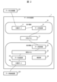
- Fig. 2 is a functional configuration diagram of the data sharing device 1.
- the data sharing device 1 stores data generated by a data generating device 101 at the top of the figure in a data storage device 102 at the bottom of the figure.
- the curved dashed line that runs from the data generating device 101 to the data storage device 102 via the data sharing device 1 represents the data path.
- the data sharing device 1 and the data storage device 102 are collectively referred to as a "communication system.”
- the data generating device 101 is, for example, a relatively old computing device with a generally fixed configuration, and its security measures are not perfect. As described in the section on the problem to be solved by the invention, even new devices can be considered to have insufficient security measures if the latest update programs cannot be installed.
- the data generating device 101 is operated without being connected to the organization's intranet (intranet) that has a communication path to the Internet, and software updates (patches) are not applied.
- the data generating device 101 can also be said to be a device that assists or substitutes for human work in various industries, and in this case, the data generating device 101 can be called "industrial equipment.”
- the data storage device 102 is a computing device, such as a server, that is connected to an intranet or the Internet and can use various software.
- the data storage device 102 generally has a large capacity data storage area. This may be separated as a storage device.
- the data sharing device 1 comprises a first environment 10, a second environment 20, and a shared memory 31.
- the shared memory may be interpreted as a shared folder as an image of a storage device.
- the first environment 10 comprises an inside port 11 and a data receiving unit 12.
- the second environment 20 comprises a data acquisition unit 22, a dedicated memory 23, an inspection unit 24, a data transmission unit 25, and an outside port 26.
- the inside port 11 is also referred to as the "first communication port” and the outside port 26 is also referred to as the "second communication port.”
- the first environment 10 and the second environment 20 operate independently. There is no communication between the first environment 10 and the second environment 20, and there is no data storage area accessible to both of them other than the shared memory 31.
- the shared memory 31 is a storage area accessible only to the data receiving unit 12 of the first environment 10 and the data acquisition unit 22 of the second environment 20. However, the shared memory 31 at least permits the data receiving unit 12 to write, and permits the data acquisition unit 22 to read. In other words, the shared memory 31 does not have to permit the data receiving unit 12 to read data, and does not have to permit writing from the data acquisition unit 22.
- the second environment 20 has limited authority to rewrite the shared memory 31 other than to delete it.
- the inner port 11 and the outer port 26 are communication ports, and correspond to, for example, IEEE 802.3.
- the inner port 11 has a communication path capable of communicating with the data generating device 101.
- the outer port 26 has a communication path capable of communicating with the data storage device 102.
- the names inner port 11 and outer port 26 are for convenience, and merely indicate that the two are physically different communication ports.
- the inner port 11 may be connected to a wide area network such as the Internet, and the outer port 26 may be connected to a small-scale network such as a local network within a premises.
- the data receiving unit 12 accepts data transmission from the data generating device 101 and writes it to the shared memory 31.
- the data acquiring unit 22 monitors the shared memory 31, and when new data is written to the shared memory 31, it copies the data to the dedicated memory 23.
- the inspection unit 24 inspects the data written to the dedicated memory 23 by the data acquisition unit 22.
- the inspection unit 24 detects malware, for example, at regular time intervals.
- the data inspection performed by the inspection unit 24 can also be called a "security check.”
- the data transmission unit 25 transmits data that has been inspected by the inspection unit 24 to the data storage device 102 via the external port 26.
- Various means can be used to send and receive data between the data receiving unit 12 and the data generating device 101.
- the second reason is that the environment for software development in the data generating device 101 may already be lost and no longer exist, making development itself impossible. As a method for doing this without adding new software, for example, any of the following can be adopted.
- the first method is to use FTP (File Transfer Protocol).
- the data receiving unit 12 is the FTP server
- the data generating device 101 is the FTP client.
- the data receiving unit 12 receives an FTP connection from the data generating device 101, it sets an area of the shared memory 31 previously mounted by the first environment 10 as the initial directory, and causes writing to be performed in that directory.
- the data generating device 101 may transfer files using a batch file created in advance, or the operator may transfer files manually.
- the data receiving unit 12 operates as an FTP server, and it is sufficient that the first environment 10 is configured to be able to write to the area of the shared memory 31 that has been mounted in advance. Since the FTP client function is often installed as standard even in relatively old OSs (operating systems), this can be realized without adding new software to the data generating device 101.
- the second method is to combine a file server function with a file copy function.
- the file server function is NFS (Network File System) or SMB (Server Message Block), with the data receiving unit 12 being the server and the data generating device 101 being the client.
- the data receiving unit 12 sets the area of the shared memory 31 that the first environment 10 has mounted in advance as shareable.
- the data generating device 101 mounts the area of the shared memory 31 provided by the data receiving unit 12, and copies data to the mounted area using the file copy function.
- the file copy function can use commands such as "cp”, “rsync”, and "robocopy”.
- File server functions and file copy functions are often standard features even in relatively old operating systems, so they can be realized without adding new software to the data generation device 101.
- Various means can be used to transmit and receive data between the data transmission unit 25 and the data storage device 102.
- the aforementioned FTP can be used, with the data storage device 102 acting as an FTP server and the data transmission unit 25 acting as an FTP client, to transfer data from the data transmission unit 25 to the data storage device 102.
- SFTP SSH File Transfer Protocol
- SCP Secure Copy Protocol
- the data sharing device 1 shown in FIG. 2 can also be said to include a first environment 10 that receives data from a data generating device 101 that is the source of the data, a shared memory 31 that stores the data received by the first environment 10, and a second environment 20 that operates independently of the first environment 10 and checks the safety of the data stored in the shared memory 31 before transmitting it to the outside.
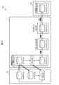
- Fig. 3 is a configuration diagram of the data sharing device 1.
- the upper part of Fig. 3 shows a hardware configuration, and the lower part of Fig. 3 shows a software configuration.
- the data sharing device 1 includes a CPU 41, a storage device 42, a RAM 43, an inner port 11, and an outer port 26.
- the CPU 41 is a central processing unit, and realizes various functions by expanding into the RAM 43 and executing a program stored in the storage device 42, which is a non-volatile storage device, for example, a flash memory.
- container technology is used as shown in the lower part of Figure 3. That is, a host OS 51 runs on hardware 50, and a container control unit 52 runs on top of that.
- the container control unit 52 manages the container in which the first environment 10 runs, the container in which the second environment 20 runs, and the shared memory 31. Note that each of the first environment 10 and the second environment 20 also includes middleware for running in the container environment, but this has been omitted for convenience of drawing.
- the first software group included in the first environment 10 is software including the data receiving unit 12.
- the second software group included in the second environment 20 is software including the data acquisition unit 22, the inspection unit 24, and the data transmission unit 25.
- the storage device 42 stores software for implementing the host OS 51 and the container control unit 52, a container for implementing the first environment 10, and a container for implementing the second environment 20.
- a portion of the RAM 43 is used as the shared memory 31 and the dedicated memory 23 for the second environment 20.
- the host OS 51 may be a real-time OS that performs real-time processing, i.e., that guarantees a response within a predetermined time, or it may not be a real-time OS.
- FIG. 4 is a diagram illustrating the operation of the data sharing system 100.
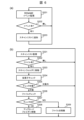
- FIG. 5 is a flowchart illustrating a communication method used between the data generating device 101 and the data sharing device 1. As shown in FIG. This communication method will be specifically described below with reference to Figures 4 and 5. Note that this corresponds to the process performed by the first environment 10 in Figure 2.
- the data generating device 101 When the data generating device 101 transmits data to the data sharing device 1, the data generating device 101 first changes the file name of the file in which the data is stored from the original file name to a dummy file name.
- the original file name is "DataFile.csv”
- the dummy file name is "Dummy.txt”.
- the data generating device 101 then transmits the data to the data sharing device 1 under the dummy file name.
- the data generating device 101 FTP transmits the transmission file to the data sharing device 1 with the name "Dummy.txt" (S101).
- the data sharing device 1 receives the data with the dummy file name.
- the data sharing device 1 receives a file with the file name "Dummy.txt" via FTP (S102).
- the data sharing device 1 then stores the data with the dummy file name.
- the data sharing device 1 stores the received file in a shared directory (FTP receiving folder). This corresponds to the operation of the data receiving unit 12 accepting data transmission from the data generating device 101 and writing it to the shared memory 31.
- FTP receiving folder shared directory
- the data generating device 101 which is the data sender, instructs the first environment 10 on the timing for storing data in the shared memory 31.
- the data generating device 101 sends a Get command to the data sharing device 1, instructing it to send back the file received from the data generating device 101.
- the data sharing device 1 receives this and sends the received file back to the data generating device 101 as is. In this case, it sends the file named "Dummy.txt" back to the data generating device 101 as is via FTP communication.
- the data generating device 101 receives this file and compares the contents of the returned data with the data before transmission. That is, it compares the data in the transmission file "DataFile.csv" with the contents of the data in "Dummy.txt" received via FTP (S103).
- the data generating device 101 sends an instruction to the data sharing device 1 to rename (RENAME) the file name from the dummy file name to the original file name. Specifically, a command to rename (RENAME) the file name is sent. As a result, the data sharing device 1 renames the file name given to the stored data from the dummy file name to the original file name. In this case, the data sharing device 1 renames (RENAME) the dummy file name "Dummy.txt" to the original name of the transmitted file "DataFile.csv" (S105). Note that in this case, it can also be said that the data generating device 101, which is the data sender, instructs the process of changing the dummy file name to the original file name.
- the data generating device 101 performs error processing (S106).
- the communication method described above when viewed from the data sharing device 1, can also be said to be a communication method executed by the data sharing device 1, in which when the first environment 10 stores data in the shared memory 31, it stores the data with a dummy file name, sends the stored data back to the data generating device 101 which is the sender, and when the data generating device 101 confirms that the contents of the data have not changed, it changes the dummy file name to the original file name.
- the communication method described above can also be said to be a communication method executed by the data generating device 101, which is the source of data when transmitting data to the data sharing device 1, which is the destination, and which changes the file name given to the data from the original file name to a dummy file name, transmits the data with the dummy file name to the data sharing device 1, compares the content of the data sent back from the data sharing device 1 with the data before transmission, and, if the content of the data has not changed, instructs processing to change the file name of the data stored in the data sharing device 1 and given the dummy file name to the original file name.
- the process of changing the original file name to a dummy file name (S101), the instruction for the data generating device 101 to send a Get command to the data sharing device 1 and send back the file received from the data generating device 101 (S103), and the instruction to change (RENAME) the file name from the dummy file name to the original file name (S105) are performed by the data generating device 101.
- This can be performed, for example, by batch processing running on the data generating device 101. However, this is not limited to this, and other processing methods may also be used.
- the above-mentioned processes that have been mainly performed by the data generating device 101 or the data sharing device 1 may be performed by the other device. That is, the processes that have been performed by the data generating device 101 may be performed by the data sharing device 1, and the processes that have been performed by the data sharing device 1 may be performed by the data generating device 101.
- the data generating device 101 performs the process of changing the original file name to a dummy file name, but the data generating device 101 may transmit a file with the original file name to the data sharing device 1, and the data sharing device 1 may perform the process of changing the original file name to a dummy file name.
- the data generating device 101 transmits a Get command, but the data sharing device 1 may perform processing to send back the received file as is, even if it does not receive a Get command from the data generating device 101.
- the data generating device 101 transmitted a command to rename (RENAME) the file, but the data generating device 101 may simply notify the data sharing device 1 that the contents were the same, and the data sharing device 1, upon receiving this, may perform a process of renaming (RENAME) the dummy file name to the original file name.
- RENAME command to rename
- the data sharing device 1 moves the data stored in the shared directory (FTP receiving folder) to a scan folder and inspects (scans) the data to see if it contains malware, etc.
- this process is performed as follows, which corresponds to the process performed by the second environment 20 in FIG. 6A and 6B are flowcharts illustrating the processing performed by the data sharing device 1 when performing an inspection (scan).
- FIG. 6A is a flowchart illustrating the process of creating a scan list as a list of files in which data to be scanned is stored.
- the data sharing device 1 monitors the above-mentioned RENAME event (S201).
- the data sharing device 1 adds the file that is the target of the RENAME event to the scan list (S202). On the other hand, if there is no event (No in S202), the process returns to S201.
- files storing data to be inspected (scanned) are added to the scan list. In this case, the timing at which the process of changing the dummy file name to the original file name shown in Figure 5 is completed can be used to start the process of verifying the safety of the data stored in shared memory 31.
- FIG. 6B is a flowchart illustrating the process of scanning data according to the scan list.
- the data sharing device 1 monitors the scan list (S301). Next, the data sharing device 1 determines whether or not there is a file in the scan list (S302). As a result, if the file is present (Yes in S302), the data sharing device 1 moves the file to the scan folder (S303). On the other hand, if the file does not exist (NO in S302), the process returns to S301.
- the data sharing device 1 checks the file extension (S304), thereby making it possible to perform a simple inspection as to whether or not the data is created in a predetermined character code.
- the data sharing device 1 performs a file check (data inspection) (S306). The contents of the file check will be described later.
- the process returns to S301.
- the data sharing device 1 moves the file from the scan folder to the upload folder (S308). On the other hand, if a problem occurs as a result of the file check (NG in S307), the data sharing device 1 isolates the file (S309) and returns to S301.
- the data sharing device 1 uploads the file moved to the upload folder to the data storage device 102.
- the data storage device 102 receives this file and stores the data.
- the second environment 20 of the data sharing device 1 may use the timing at which the process of changing the dummy file name to the original file name shown in FIG. 5 is completed to transmit the data stored in the shared memory 31 to the external data storage device 102.
- the second environment 20 of the data sharing device 1 deletes the data stored in the shared memory 31 after completing transmission of the data stored in the shared memory 31 to the external data storage device 102.
- the data generating device 101 which is the data sender, may then use the timing when the data stored in the shared memory 31 is deleted by the second environment 20, or based on a specified interval, to send a file containing the next data to be stored in the shared memory 31.
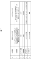
- FIG. 7 is a table showing the process of performing a file check (data inspection).
- file checks involve checking whether or not the data contains malware.
- a character code check is performed as shown in Fig. 7 as a normalization check method.
- the normalization check method uses the "iconv" command to check whether the data in the file is configured in any one of the character codes ASCII, UTF-8, or Shift_JIS.
- 7 shows a virus check method as a conventional check method, which uses virus check software to check whether the data in a file contains a virus pattern.
- the normalization check method requires less memory capacity than the virus check method. Also, the normalization check method has a much shorter startup time than the virus check method. Furthermore, the virus check method requires software maintenance and hardware maintenance, but the normalization check method does not.
- the data generated by the data generating device 101 is data output from devices or equipment operating at manufacturing sites and the like, and is described in text data and does not include binary code. On the other hand, it is difficult to describe malware in text data, and it is described in binary code. Therefore, in this embodiment, when the data includes a code other than a predetermined character code, the data generating device 101 determines that the data includes malware. This provides the advantages of requiring only a small amount of memory when performing a file check (data inspection), extremely short startup time, and no software or hardware maintenance.
- the inspection method described above corresponds to the processing performed by the inspection unit 24 of the second environment 20. Therefore, the inspection method described above can also be said to be an inspection method executed by the data sharing device 1, in which the inspection unit 24 of the second environment 20 determines whether the data is created using a predetermined character code, thereby inspecting whether the data contains malware.
- the inspection unit 24 of the second environment 20 may determine whether the data is garbled or not, and if so, output a notification to that effect.
- This notification may be sent, for example, to the data generating device 101, and processing such as retransmitting the data from the data generating device 101 may be performed.
- the data sharing device 1 also transmits the data stored in the shared memory 31 to the external data storage device 102 while maintaining the directory structure of the file in which the received data is stored.
- 8A to 8C are diagrams showing the transition of the directory structure of a folder in which data is stored.
- 8A shows a directory structure of folders and files in which data generated by the data generating device 101 is stored.
- files with the extension "txt” store data generated by the data generating device 101.
- a directory structure is formed with a folder indicated by "ProductData” at the top level.
- Fig. 8B shows the directory structure after these folders and files are copied using the Windows (registered trademark) "xcopy” command.
- a directory structure is formed with the folder indicated by "TESTDATA" at the top, but the directory structure is the same as that in Fig. 8A.
- Fig. 8(c) shows the directory structure of folders and files in which data is stored in the data storage device 102.
- a directory structure is formed in which the folder indicated by "TESTDATA" is at the top, but the directory structure is the same as in Figs. 8(a) and (b).
- the data storage device 102 can distinguish which data generating device 101 generated the data, improving the usability for users who utilize this data.
- the data sharing device 1 includes a first environment 10 having an inside port 11, which is a first communication port that receives data from a data sender, a second environment 20 having an outside port 26, which is a second communication port, and operating independently of the first environment 10, and a shared memory 31 accessible from both the first environment 10 and the second environment 20.
- the first environment 10 includes a data receiving unit 12 that stores data received via the inside port 11 in the shared memory 31, and the second environment 20 includes a data sending unit 25 that transmits data stored in the shared memory 31 to the outside via the outside port 26, which is a second communication port, and an inspection unit 24 that checks the safety of the data stored in the shared memory 31.
- the first environment 10 When storing data in the shared memory 31, the first environment 10 stores the data under a dummy file name, sends the stored data back to the sender, and when it is confirmed that the contents of the data have not changed at the sender, it changes the dummy file name to the original file name.
- the data sharing device 1 described above comprises a first environment 10 having an inside port 11, which is a first communication port that receives data from a data sender; a second environment 20 having an outside port 26, which is a second communication port, and operating independently of the first environment 10; and a shared memory 31 accessible from both the first environment 10 and the second environment 20.
- the first environment 10 comprises a data receiving unit 12 that stores data received via the inside port 11 in the shared memory 31.
- the second environment 20 comprises a data sending unit 25 that sends data stored in the shared memory 31 to the outside via the outside port 26, which is a second communication port, and an inspection unit 24 that checks the safety of the data stored in the shared memory 31.
- the inspection unit 24 can also be considered to inspect whether the data contains malware by determining whether the data is created using a predetermined character code.
- the data generating device 101 also has characteristics as a device.
- the data generating device 101 can be considered to be a data generating device that includes a change unit that changes the file name given to the generated data from the original file name to a dummy file name, a transmission unit that transmits the data with the dummy file name to the destination, a comparison unit that compares the content of the data sent back from the data destination with the data before transmission, and an instruction unit that instructs processing to change the file name of the data stored at the destination and given the dummy file name to the original file name when the content of the data has not changed.
- the processing performed by the data sharing device 1 described above is realized by the cooperation of software and hardware resources. That is, a processor such as the CPU 41 inside the computer provided in the data sharing device 1 loads software (programs) that realize each of the above-mentioned functions into a memory such as the RAM 43 and executes them to realize each of these functions.
- a processor such as the CPU 41 inside the computer provided in the data sharing device 1 loads software (programs) that realize each of the above-mentioned functions into a memory such as the RAM 43 and executes them to realize each of these functions.
- the processing performed by the data sharing device 1 can also be considered to be a program executed by the data sharing device 1, which provides the computer with the following functions: when the first environment 10 stores data in the shared memory 31, storing data with a dummy file name; sending the stored data back to the data generating device 101 which is the sender; and changing the dummy file name to the original file name when the data generating device 101 confirms that the contents of the data have not changed.
- the processing performed by the data sharing device 1 can also be considered to be a program executed by the data sharing device 1, which realizes the function of inspecting whether or not the data contains malware by determining whether or not the data has been created using a predetermined character code in the inspection unit 24 of the second environment 20.
- the processing performed by the data generating device 101 is also realized by the cooperation of software and hardware resources. Therefore, the processing performed by the data generating device 101 can also be considered to be a program executed by the data generating device 101, which is the source of data, when sending data to the destination data sharing device 1, and which realizes the following functions: changing the file name given to the data from the original file name to a dummy file name; sending the data given the dummy file name to the data sharing device 1; comparing the content of the data sent back from the data sharing device 1 with the data before sending; and, when the content of the data has not changed, instructing processing to change the file name of the data stored in the data sharing device 1 and given a dummy file name to the original file name.
- the program for implementing this embodiment can of course be provided via communication means, but it can also be provided stored on a recording medium such as a CD-ROM.
- Reference Signs List 1 Data sharing device, 10: First environment, 11: Inside port, 12: Data receiving unit, 20: Second environment, 22: Data acquisition unit, 23: Dedicated memory, 24: Inspection unit, 25: Data transmission unit, 26: Outside port, 31: Shared memory, 100: Data sharing system, 101, 101a, 101b, 10c: Data generating device, 102: Data storage device
Landscapes
- Engineering & Computer Science (AREA)
- Computer Security & Cryptography (AREA)
- Theoretical Computer Science (AREA)
- Computer Hardware Design (AREA)
- Physics & Mathematics (AREA)
- General Engineering & Computer Science (AREA)
- Software Systems (AREA)
- General Physics & Mathematics (AREA)
- General Health & Medical Sciences (AREA)
- Health & Medical Sciences (AREA)
- Bioethics (AREA)
- Mathematical Physics (AREA)
- Virology (AREA)
- Information Retrieval, Db Structures And Fs Structures Therefor (AREA)
- Storage Device Security (AREA)
Abstract
データの送信元からデータを受信する第1環境10と、第1環境10が受信したデータを格納する共有メモリ31と、第1環境10とは独立に動作し、共有メモリ31に格納されたデータの安全性を確認して外部に送信する第2環境20と、を備えるデータ共有装置1が実行する通信方法であって、第1環境10は、共有メモリ31にデータを格納する際に、データをダミーのファイル名にて格納し、格納したデータを送信元に送り返し、送信元でデータの内容が変化していないことを確認したときに、ダミーのファイル名を本来のファイル名に変更する、通信方法。これにより、生成したデータをデータ共有装置に送信する際に、データが欠損したときでもこれを検知できる通信方法を提供することができる。また、より簡便な方法でマルウェアを検出することができる検査方法を提供することができる。
Description
本発明は、通信方法、検査方法、データ共有システムに関する。本発明は、特に、生成したデータを、このデータを格納するデータ格納装置に送信する際に好適に使用できる通信方法等に関する。
例えば、製造現場などで稼働する装置や設備には、データを生成するのにPC(Personal Computer)が利用されることが多い。しかし、これらの装置や設備は、その更新サイクルが比較的長いため、これらに接続するPCのOS(Operating System)のアップデートは頻繁には行われないのが一般的である。そのため、これらのPCは、セキュリティの観点より、通常は情報ネットワークに接続できないため、生成したデータを簡単には利用ができない問題が発生している。
これを解決するため、PCを情報ネットワークに接続するが、生成したデータを検査した上で上位サーバ等に受け渡すことで、セキュリティを確保しつつ生成したデータを活用可能とするデータ共有装置が用いられることがある。
これを解決するため、PCを情報ネットワークに接続するが、生成したデータを検査した上で上位サーバ等に受け渡すことで、セキュリティを確保しつつ生成したデータを活用可能とするデータ共有装置が用いられることがある。
特許文献1には、データ共有装置は、第1通信ポートを有する第1環境と、第2通信ポートを有し第1環境とは独立に動作する第2環境と、第1環境および第2環境の双方からアクセス可能な共有メモリと、を備えるデータ共有装置が開示されている。第1環境は、第1通信ポートを介して受信したデータを共有メモリに格納するデータ受信部を備える。第2環境は、第2環境内からのみアクセス可能な専用メモリと、共有メモリに格納されたデータを専用メモリに書き込むデータ取得部と、専用メモリに格納されたデータの安全性を確認する検査部と、専用メモリに格納されたデータを第2通信ポートを介して外部に送信するデータ送信部と、を備える。
上記PC等のデータ生成機器が、生成したデータをデータ共有装置に送信する際には、例えば、FTP(File Transfer Protocol)にて行われる。
しかしながら、この場合、データ共有装置のメモリの不足等の要因によりファイルの欠損が生じることがある。ただし、この場合でも送信が成功したと扱われるため、データが欠損したままデータ共有装置から上位サーバ等に送られてしまう問題がある。
また、データの検査として例えば、マルウェアを検出するときに、ウィルスチェックソフトウェアを使用すると、必要なメモリが不足しやすく、また検査に多大な時間を要する。
本発明は、生成したデータをデータ共有装置に送信する際に、データが欠損したときでもこれを検知できる通信方法を提供することを目的とする。また、本発明は、より簡便な方法でマルウェアを検出することができる検査方法を提供することを目的とする。
しかしながら、この場合、データ共有装置のメモリの不足等の要因によりファイルの欠損が生じることがある。ただし、この場合でも送信が成功したと扱われるため、データが欠損したままデータ共有装置から上位サーバ等に送られてしまう問題がある。
また、データの検査として例えば、マルウェアを検出するときに、ウィルスチェックソフトウェアを使用すると、必要なメモリが不足しやすく、また検査に多大な時間を要する。
本発明は、生成したデータをデータ共有装置に送信する際に、データが欠損したときでもこれを検知できる通信方法を提供することを目的とする。また、本発明は、より簡便な方法でマルウェアを検出することができる検査方法を提供することを目的とする。
上記の課題を解決するため本発明は、データの送信元からデータを受信する第1環境と、第1環境が受信したデータを格納する共有メモリと、第1環境とは独立に動作し、共有メモリに格納されたデータの安全性を確認して外部に送信する第2環境と、を備えるデータ共有装置が実行する通信方法であって、第1環境は、共有メモリにデータを格納する際に、データをダミーのファイル名にて格納し、格納したデータを送信元に送り返し、送信元でデータの内容が変化していないことを確認したときに、ダミーのファイル名を本来のファイル名に変更する、通信方法を提供できる。この場合、生成したデータをデータ共有装置に送信する際に、データが欠損したときでもこれを検知できる通信方法を提供できる。
ここで、第2環境は、第1環境がダミーのファイル名を本来のファイル名に変更する処理が完了したタイミングを利用して、共有メモリに格納されたデータに対し、データの安全性を確認する処理を開始することができる。この場合、データの欠損がないことを担保したうえで次の処理を行うことができる。
また、第2環境は、第1環境が受信したデータが格納されるファイルのディレクトリ構造を維持した状態で、共有メモリに格納されたデータを外部に送信することができる。この場合、データを利用するユーザの利便性が向上する。
さらに、第2環境は、第1環境がダミーのファイル名を本来のファイル名に変更する処理が完了したタイミングを利用して、共有メモリに格納されたデータを外部に送信することができる。この場合、データの欠損がないことを担保したうえでデータを外部に送信することができる。
またさらに、第2環境は、共有メモリに格納されたデータを外部に送信完了したのちに、共有メモリに格納されたデータを削除することができる。この場合、さらに次のデータを受け付けることができる。
そして、第2環境は、共有メモリに対して削除する以外の書き換え権限が制限されるようにできる。この場合、セキュリティを確保することができる。
また、データの送信元が、第1環境が共有メモリにデータを格納するタイミング、およびダミーのファイル名を本来のファイル名に変更する処理を指示することができる。この場合、バッチ処理等を利用してより容易に処理を行うことができる。
さらに、データの送信元は、共有メモリに格納されたデータが第2環境により削除されたタイミングを利用して、若しくは、所定のインターバルに基づき、次のデータを共有メモリに格納することができる。この場合、共有メモリの容量を削減できる。
また、第2環境は、第1環境が受信したデータが格納されるファイルのディレクトリ構造を維持した状態で、共有メモリに格納されたデータを外部に送信することができる。この場合、データを利用するユーザの利便性が向上する。
さらに、第2環境は、第1環境がダミーのファイル名を本来のファイル名に変更する処理が完了したタイミングを利用して、共有メモリに格納されたデータを外部に送信することができる。この場合、データの欠損がないことを担保したうえでデータを外部に送信することができる。
またさらに、第2環境は、共有メモリに格納されたデータを外部に送信完了したのちに、共有メモリに格納されたデータを削除することができる。この場合、さらに次のデータを受け付けることができる。
そして、第2環境は、共有メモリに対して削除する以外の書き換え権限が制限されるようにできる。この場合、セキュリティを確保することができる。
また、データの送信元が、第1環境が共有メモリにデータを格納するタイミング、およびダミーのファイル名を本来のファイル名に変更する処理を指示することができる。この場合、バッチ処理等を利用してより容易に処理を行うことができる。
さらに、データの送信元は、共有メモリに格納されたデータが第2環境により削除されたタイミングを利用して、若しくは、所定のインターバルに基づき、次のデータを共有メモリに格納することができる。この場合、共有メモリの容量を削減できる。
また、上記の課題を解決するため本発明は、データを送信先に送信するときに、データの送信元が実行する通信方法であって、データに付されるファイル名を、本来のファイル名からダミーのファイル名に変更し、ダミーのファイル名が付されたデータを送信先に送信し、データの送信先から送り返されたデータと送信前のデータとの内容を比較し、データの内容が変化していないときに、送信先に格納されダミーのファイル名が付されたデータについて本来のファイル名に変更するための処理を指示する、通信方法である。この場合、生成したデータをデータ共有装置に送信する際に、データが欠損したときでもこれを検知できる通信方法を提供できる。
ここで、データの送信先から送り返されたデータと送信前のデータとの内容を比較することで、FTP(File Transfer Protocol)にてデータを送信元から送信先に送信するときに生じるデータの欠損を検知することができる。この場合、データをFTPにより送信したとき、データが欠損してもこれを検知できる。
さらに、上記の課題を解決するため本発明は、データの送信元からデータを受信する第1環境と、第1環境が受信したデータを格納する共有メモリと、第1環境とは独立に動作し、共有メモリに格納されたデータの安全性を確認して外部に送信する第2環境と、を備えるデータ共有装置が実行する検査方法であって、第2環境にて、データが予め定められた文字コードにより作成されているか否かを判別することで、データにマルウェアが含まれるか否かを検査する、検査方法である。この場合、より簡便な方法でマルウェアを検出することができる検査方法を提供することができる。
ここで、第2環境は、データに文字化けしているか否かを判断し、文字化けしていたときはその旨の通知を出力することができる。この場合、文字化けしたデータを排除することができる。
また、文字コードは、ASCII、UTF-8、Shift_JISの何れか1つにすることができる。この場合、文字コードを検知する際に、検知対象としてより適したものを適用することができる。
また、文字コードは、ASCII、UTF-8、Shift_JISの何れか1つにすることができる。この場合、文字コードを検知する際に、検知対象としてより適したものを適用することができる。
さらに、上記の課題を解決するため本発明は、データを生成するデータ生成機器と、データ生成機器が生成したデータを検査しデータを格納するデータ格納装置に送信するデータ共有装置と、を備え、データ共有装置は、データの送信元からデータを受信する第1通信ポートを有する第1環境と、第2通信ポートを有し第1環境とは独立に動作する第2環境と、第1環境および第2環境の双方からアクセス可能な共有メモリと、を備え、第1環境は、第1通信ポートを介して受信したデータを共有メモリに格納するデータ受信部を備え、第2環境は、共有メモリに格納されたデータを第2通信ポートを介して外部に送信するデータ送信部と、共有メモリに格納されたデータの安全性を確認する検査部と、を備え、第1環境は、共有メモリにデータを格納する際に、データをダミーのファイル名にて格納し、格納したデータを送信元に送り返し、送信元でデータの内容が変化していないことを確認したときに、ダミーのファイル名を本来のファイル名に変更する、データ共有システムである。この場合、生成したデータをデータ共有装置に送信する際に、データが欠損したときでもこれを検知できるデータ共有システムを提供できる。
本発明によれば、生成したデータをデータ共有装置に送信する際に、データが欠損したときでもこれを検知できる通信方法を提供することができる。また、本発明によれば、より簡便な方法でマルウェアを検出することができる検査方法を提供することができる。
以下、添付図面を参照し、本発明の実施の形態について、詳細に説明する。
<データ共有システム100の全体構成の説明>
図1は、本実施の形態におけるデータ共有システム100の構成例を示す図である。
図示するデータ共有システム100は、データを生成するデータ生成機器101a、101b、101cと、データ生成機器101a、101b、101cが生成したデータを検査しデータ格納装置102に送信するデータ共有装置1と、データを格納するデータ格納装置102とが、ネットワーク40を介し接続されている。
データ生成機器101a、101b、101cは、例えば、製造現場などで稼働する装置や設備に接続され、これらのデータを収集するのに使用される。データ生成機器101a、101b、101cは、コンピュータ装置であり、例えば、PCである。ただし、これに限られるものではなく、モバイルコンピュータ、スマートフォン、タブレットなどであってもよい。データ生成機器101a、101b、101cは、ここでは3つを図示しているが、その数は、1つ以上であればいくつであってもよい。なお、以下、データ生成機器101a、101b、101cをそれぞれ区別しない場合は、単に「データ生成機器101」と言うことがある。
図1は、本実施の形態におけるデータ共有システム100の構成例を示す図である。
図示するデータ共有システム100は、データを生成するデータ生成機器101a、101b、101cと、データ生成機器101a、101b、101cが生成したデータを検査しデータ格納装置102に送信するデータ共有装置1と、データを格納するデータ格納装置102とが、ネットワーク40を介し接続されている。
データ生成機器101a、101b、101cは、例えば、製造現場などで稼働する装置や設備に接続され、これらのデータを収集するのに使用される。データ生成機器101a、101b、101cは、コンピュータ装置であり、例えば、PCである。ただし、これに限られるものではなく、モバイルコンピュータ、スマートフォン、タブレットなどであってもよい。データ生成機器101a、101b、101cは、ここでは3つを図示しているが、その数は、1つ以上であればいくつであってもよい。なお、以下、データ生成機器101a、101b、101cをそれぞれ区別しない場合は、単に「データ生成機器101」と言うことがある。
データ格納装置102は、データ共有システム100の全体の管理をするサーバコンピュータである。データ格納装置102は、製造現場などで稼働する装置や設備を管理するなどの用途に利用するため、データ生成機器101が生成したデータを収集し保存する。
なお、図示するデータ格納装置102は、1つであるが、複数のサーバコンピュータによりその機能を実現してもよい。また、データ格納装置102は、仮想サーバ装置であってもよい。
なお、図示するデータ格納装置102は、1つであるが、複数のサーバコンピュータによりその機能を実現してもよい。また、データ格納装置102は、仮想サーバ装置であってもよい。
ネットワーク40は、データ共有装置1を境界として、現場系ネットワーク40aと情報系ネットワーク40bとに分かれている。
現場系ネットワーク40aは、例えば、製造現場に設けられるネットワークであり、データ生成機器101とデータ共有装置1との情報通信に用いられる通信手段である。現場系ネットワーク40aは、例えば、製造現場など特定のエリアだけで使用されるネットワークであり、ここでは、データ生成機器101およびデータ共有装置1以外の装置と接続しない。現場系ネットワーク40aは、例えば、LAN(Local Area Network)である。
情報系ネットワーク40bは、データ共有装置1とデータ格納装置102との間の情報通信に用いられる通信手段である。図示する情報系ネットワーク40bは、データ共有装置1およびデータ格納装置102と接続するが、他の外部装置とも接続可能なネットワークである。情報系ネットワーク40bは、例えば、LAN、WAN(Wide Area Network)、インターネットである。
本実施の形態のネットワーク40に用いられる通信回線は、有線か無線かを問わず、またこれらを併用してもよい。また、ゲートウェイ装置やルータ等の中継装置を使用することで、複数のネットワークから構成されるものであってもよい。
現場系ネットワーク40aは、例えば、製造現場に設けられるネットワークであり、データ生成機器101とデータ共有装置1との情報通信に用いられる通信手段である。現場系ネットワーク40aは、例えば、製造現場など特定のエリアだけで使用されるネットワークであり、ここでは、データ生成機器101およびデータ共有装置1以外の装置と接続しない。現場系ネットワーク40aは、例えば、LAN(Local Area Network)である。
情報系ネットワーク40bは、データ共有装置1とデータ格納装置102との間の情報通信に用いられる通信手段である。図示する情報系ネットワーク40bは、データ共有装置1およびデータ格納装置102と接続するが、他の外部装置とも接続可能なネットワークである。情報系ネットワーク40bは、例えば、LAN、WAN(Wide Area Network)、インターネットである。
本実施の形態のネットワーク40に用いられる通信回線は、有線か無線かを問わず、またこれらを併用してもよい。また、ゲートウェイ装置やルータ等の中継装置を使用することで、複数のネットワークから構成されるものであってもよい。
<データ共有装置1の機能構成の説明>
図2は、データ共有装置1の機能構成図である。データ共有装置1は、図示上部のデータ生成機器101が生成するデータを、図示下部のデータ格納装置102に格納する。図2においてデータ生成機器101からデータ共有装置1を経由してデータ格納装置102に至る破線で示す曲線は、データの経路を表している。なお以下では、データ共有装置1およびデータ格納装置102をまとめて「通信システム」とも呼ぶ。
図2は、データ共有装置1の機能構成図である。データ共有装置1は、図示上部のデータ生成機器101が生成するデータを、図示下部のデータ格納装置102に格納する。図2においてデータ生成機器101からデータ共有装置1を経由してデータ格納装置102に至る破線で示す曲線は、データの経路を表している。なお以下では、データ共有装置1およびデータ格納装置102をまとめて「通信システム」とも呼ぶ。
データ生成機器101はたとえば構成が概ね固定された比較的古い演算装置であり、セキュリティ対策が万全ではない。発明が解決しようとする課題の欄に記載したように、新しい機器でも最新の更新プログラムを導入できない場合は同様にセキュリティ対策が万全でないとみなすことができる。データ生成機器101はたとえば、インターネットとも接続される通信経路を有するその組織のイントラネット(構内ネットワーク)やインターネット等に接続されることなく運用され、ソフトウェアの更新プログラム(パッチ)などが当てられていない。データ生成機器101は、様々な産業において人間が行う作業の補助や代行を行う機器と言うこともでき、この場合にデータ生成機器101は「産業機器」と呼ぶことができる。データ格納装置102は、構内ネットワークやインターネットに接続され、様々なソフトウェアが利用可能な演算装置、たとえばサーバである。データ格納装置102は一般に大容量のデータ格納領域を有する。これはストレージ装置として分離されていてもよい。
データ共有装置1は、第1環境10と、第2環境20と、共有メモリ31と、を備える。共有メモリはストレージ装置のイメージとしての共有フォルダと読み替えてもよい。第1環境10は、内側ポート11と、データ受信部12と、を備える。第2環境20は、データ取得部22と、専用メモリ23と、検査部24と、データ送信部25と、外側ポート26と、を備える。なお以下では、内側ポート11を「第1通信ポート」とも呼び、外側ポート26を「第2通信ポート」とも呼ぶ。
第1環境10と第2環境20は独立して動作する。第1環境10と第2環境20の間の通信は行われず、共有メモリ31以外は両者がアクセス可能なデータ保存領域は存在しない。共有メモリ31は、第1環境10のデータ受信部12および第2環境20のデータ取得部22のみがアクセス可能な記憶領域である。ただし共有メモリ31は、データ受信部12に対して少なくとも書き込みを許可し、データ取得部22に読み出しを許可する。換言すると共有メモリ31は、データ受信部12に対してデータの読み出しを許可しなくてもよいし、データ取得部22からの書き込みを許可しなくてもよい。実際には、第2環境20は、共有メモリ31に対して削除する以外の書き換え権限が制限されている。
内側ポート11および外側ポート26は通信ポートであり、たとえばIEEE802.3に対応する。内側ポート11は、データ生成機器101と通信可能な通信路を有する。外側ポート26は、データ格納装置102と通信可能な通信路を有する。なお、内側ポート11および外側ポート26の名称は便宜的なものであり、両者は物理的に異なる通信ポートであることを示しているにすぎない。たとえば内側ポート11がインターネットなどの広域のネットワークに接続され、外側ポート26が構内のローカルネットワークなど小規模なネットワークに接続されてもよい。
データ受信部12は、データ生成機器101からのデータ送信を受け付けて共有メモリ31に書き込む。データ取得部22は共有メモリ31を監視し、共有メモリ31に新たなデータが書き込まれると、そのデータを専用メモリ23にコピーする。
検査部24は、データ取得部22が専用メモリ23に書き込んだデータの検査を行う。検査部24はたとえば一定時間ごとに、マルウェアを検出する。なお、検査部24が実行するデータの検査は、「セキュリティチェック」とも呼べる。
データ送信部25は、検査部24による検査が完了したデータを対象として、外側ポート26を経由してデータ格納装置102に送信する。
データ受信部12とデータ生成機器101との間のデータ送受信には、様々な手段を用いることができる。ただし、データ生成機器101には新たなソフトウェアを追加しないことが望ましい。これは主に次の2つの理由による。第1の理由は、新たなソフトウェアがデータ生成機器101のその他のプログラム動作に悪影響を与えないことを、新たなソフトウェアを導入する前に多大なコストをかけて事前検証を行う必要がある場合があるからである。第2の理由は、データ生成機器101においてソフトウェア開発を行うための環境が既に失われて存在せず、開発自体が行えない場合があるからである。新たなソフトウェアを追加せずに行う方法として、たとえば次のいずれかを採用できる。
第1の手法は、FTP(File Transfer Protocol)を利用する方法である。この場合は、データ受信部12がFTPサーバ、データ生成機器101がFTPクライアントとなる。データ受信部12は、データ生成機器101からのFTP接続を受けると、第1環境10があらかじめマウントした共有メモリ31の領域を初期ディレクトリとし、そのディレクトリへの書き込みを行わせる。この場合に、データ生成機器101ではあらかじめ作成したバッチファイルを用いてファイルを転送してもよいし、オペレータが手動操作でファイルを転送してもよい。
またこの場合にデータ受信部12は、FTPサーバとして動作しており、第1環境10があらかじめマウントした共有メモリ31の領域に書き込みが可能なように設定がされていればよい。FTPクライアント機能は比較的古いOS(オペレーティングシステム)でも標準搭載されていることが多いので、データ生成機器101に新たなソフトウェアを追加することなく実現できる。
第2の手法は、ファイルサーバ機能とファイルコピー機能を組み合わせる方法である。ファイルサーバ機能は、NFS(Network File System)やSMB(Server Message Block)であり、データ受信部12がサーバ、データ生成機器101がクライアントとなる。データ受信部12は、第1環境10があらかじめマウントした共有メモリ31の領域を共有可能に設定する。データ生成機器101はデータ受信部12が提供する共有メモリ31の領域をマウントし、ファイルコピー機能によりマウントした領域にデータをコピーする。
ファイルコピー機能は、たとえば「cp」、「rsync」、および「robocopy」などのコマンドを利用できる。ファイルサーバ機能およびファイルコピー機能は、比較的古いOSでも標準搭載されていることが多いので、データ生成機器101に新たなソフトウェアを追加することなく実現できる。
データ送信部25とデータ格納装置102との間のデータ送受信には、様々な手段を用いることができる。たとえば前述のFTPを利用し、データ格納装置102がFTPサーバ、データ送信部25がFTPクライアントとなって、データ送信部25からデータ格納装置102にデータを転送してもよい。また、FTPの代わりにSFTP(SSH File Transfer Protocol)やSCP(Secure Copy Protocol)を用いてもよい。
図2で示したデータ共有装置1は、データの送信元であるデータ生成機器101からデータを受信する第1環境10と、第1環境10が受信したデータを格納する共有メモリ31と、第1環境10とは独立に動作し、共有メモリ31に格納されたデータの安全性を確認して外部に送信する第2環境20と、を備える、と言うこともできる。
<データ共有装置1の装置構成>
図3は、データ共有装置1の構成図である。図3の上部にはハードウェア構成を示し、図3の下部にはソフトウェア構成を示す。データ共有装置1は、CPU41と、記憶装置42と、RAM43と、内側ポート11と、外側ポート26と、を備える。CPU41は中央演算装置であり、不揮発性の記憶装置、たとえばフラッシュメモリである記憶装置42に格納されるプログラムを、RAM43に展開して実行することで様々な機能を実現する。
図3は、データ共有装置1の構成図である。図3の上部にはハードウェア構成を示し、図3の下部にはソフトウェア構成を示す。データ共有装置1は、CPU41と、記憶装置42と、RAM43と、内側ポート11と、外側ポート26と、を備える。CPU41は中央演算装置であり、不揮発性の記憶装置、たとえばフラッシュメモリである記憶装置42に格納されるプログラムを、RAM43に展開して実行することで様々な機能を実現する。
本実施の形態では、図3の下部に示すようにコンテナ技術が用いられる。すなわち、ハードウェア50の上でホストOS51が動作しており、さらにその上にコンテナ制御部52が動作する。コンテナ制御部52は、第1環境10が動作するコンテナと、第2環境20が動作するコンテナと、共有メモリ31とを管理する。なお第1環境10および第2環境20のそれぞれには、コンテナ環境で動作するためのミドルウエアも含まれるが、作図の都合により省略している。
第1環境10に含まれる第1ソフトウェア群とは、データ受信部12を含むソフトウェアである。第2環境20に含まれる第2ソフトウェア群とは、データ取得部22、検査部24、およびデータ送信部25を含むソフトウェアである。記憶装置42には、ホストOS51およびコンテナ制御部52を実現するためのソフトウェアと、第1環境10を実現するコンテナ、および第2環境20を実現するコンテナが格納される。RAM43の一部が共有メモリ31や第2環境20の専用メモリ23として利用される。なおホストOS51は、リアルタイム処理、すなわち、あらかじめ定められた時間内での応答を保証するリアルタイムOSでもよいし、リアルタイムOSでなくてもよい。
<データ共有システム100の動作の説明>
図4は、データ共有システム100の動作について説明した図である。
ここではまず、データ生成機器101とデータ共有装置1との間で用いられる通信方法について説明を行う。
図5は、データ生成機器101とデータ共有装置1との間で用いられる通信方法について説明したフローチャートである。
以下、図4、5を用いてこの通信方法について具体的に説明する。なお、これは、図2では、第1環境10が行う処理に対応する。
図4は、データ共有システム100の動作について説明した図である。
ここではまず、データ生成機器101とデータ共有装置1との間で用いられる通信方法について説明を行う。
図5は、データ生成機器101とデータ共有装置1との間で用いられる通信方法について説明したフローチャートである。
以下、図4、5を用いてこの通信方法について具体的に説明する。なお、これは、図2では、第1環境10が行う処理に対応する。
データ生成機器101が、データ共有装置1にデータを送信する際には、まず、データ生成機器101が、データが格納されるファイルのファイル名を本来のファイル名からダミーのファイル名に変更する。ここでは、本来のファイル名が、「DataFile.csv」であり、ダミーのファイル名が、「Dummy.txt」であるとする。そして、データ生成機器101は、データ共有装置1に対し、データをダミーのファイル名にて送信する。この場合、データ生成機器101は、データ共有装置1に対し、送信ファイルを「Dummy.txt」という名称でFTP送信する(S101)。
データ共有装置1では、ダミーのファイル名が付されたデータを受信する。この場合、データ共有装置1は、ファイル名が「Dummy.txt」のファイルをFTP受信する(S102)。そして、データ共有装置1は、ダミーのファイル名が付されたデータを格納する。この場合、データ共有装置1では、受信したファイルを共有ディレクトリ(FTP受信フォルダ)に格納する。これは、データ受信部12が、データ生成機器101からのデータ送信を受け付けて共有メモリ31に書き込む動作に対応する。なおこの場合、データ送信元であるデータ生成機器101が、第1環境10が共有メモリ31にデータを格納するタイミングを指示する、と言うこともできる。
次に、データ生成機器101が、データ共有装置1に対しGetコマンドを送信し、データ生成機器101から受信したファイルを送り返す指示を出す。これを受けたデータ共有装置1は、データ生成機器101に対し、受信したファイルをそのまま送り返す。この場合、ファイル名が「Dummy.txt」のファイルをそのままデータ生成機器101にFTP通信にて送り返す。データ生成機器101では、このファイルを受信し、送り返されたデータと送信前のデータの内容を比較する。即ち、送信ファイルである「DataFile.csv」のデータとFTP受信した「Dummy.txt」のデータの内容を比較する(S103)。
そして、その比較結果が、変化せず同じ内容であった場合(S104でOK)、データ生成機器101は、データ共有装置1に対し、ファイル名をダミーのファイル名から本来のファイル名に変更(RENAME)する指示を送信する。具体的には、ファイル名を変更(RENAME)するコマンドを送信する。その結果、データ共有装置1は、格納されたデータに付されたファイル名を、ダミーのファイル名から本来のファイル名に変更する。この場合、データ共有装置1は、ダミーのファイル名である「Dummy.txt」を本来の送信ファイルの名称である「DataFile.csv」に変更(RENAME)する(S105)。なお、この場合、データ送信元であるデータ生成機器101が、ダミーのファイル名を本来のファイル名に変更する処理を指示する、と言うこともできる。
一方、比較結果が、異なる内容であった場合(S104でNG)、データ生成機器101は、エラー処理を行う(S106)。
以上説明した通信方法は、データ共有装置1から見た場合、データ共有装置1が実行する通信方法であって、第1環境10が、共有メモリ31にデータを格納する際に、データをダミーのファイル名にて格納し、格納したデータを送信元であるデータ生成機器101に送り返し、データ生成機器101でデータの内容が変化していないことを確認したときに、ダミーのファイル名を本来のファイル名に変更する、通信方法である、と言うこともできる。
また、以上説明した通信方法は、データ生成機器101から見た場合、データを送信先であるデータ共有装置1に送信するときに、データの送信元であるデータ生成機器101が実行する通信方法であって、データに付されるファイル名を、本来のファイル名からダミーのファイル名に変更し、ダミーのファイル名が付されたデータをデータ共有装置1に送信し、データ共有装置1から送り返されたデータと送信前のデータとの内容を比較し、データの内容が変化していないときに、データ共有装置1に格納されダミーのファイル名が付されたデータについて本来のファイル名に変更するための処理を指示する、通信方法である、と言うこともできる。
このような通信方法を採用した場合、データ生成機器101がデータ共有装置1にデータを送信する際に、データが欠損したときでもこれを検知することができる。つまり、FTPによりデータ生成機器101がデータ共有装置1にデータを送信したときに、データ共有装置1のメモリの不足等の要因によりファイルの欠損が生じた場合でも、これを検知し、例えば、再度送信するなどの処理を行うことができる。これにより、データ生成機器101がデータ共有装置1にデータを送信する際に、正常なデータを送信でき、さらにデータ格納装置102でも正常なデータを格納することができる。
なお、図5において、本来のファイル名からダミーのファイル名に変更する処理(S101)、データ生成機器101が、データ共有装置1に対しGetコマンドを送信し、データ生成機器101から受信したファイルを送り返す指示(S103)、ファイル名をダミーのファイル名から本来のファイル名に変更(RENAME)する指示(S105)は、データ生成機器101が行っていた。これは、例えば、データ生成機器101で動作するバッチ処理により行うことができる。ただし、これに限られるものではなく、他の処理方法により行ってもよい。
また、上述した処理でデータ生成機器101やデータ共有装置1が主体となって行っていた処理は、他方の装置で行うようにしてもよい。即ち、データ生成機器101が行っていた処理を、データ共有装置1が行うようにしてもよく、データ共有装置1が行っていた処理をデータ生成機器101が行うようにしてもよい。
例えば、S101~S102において、データ生成機器101が、本来のファイル名からダミーのファイル名に変更する処理をしていたが、データ生成機器101は、本来のファイル名が付されたファイルをデータ共有装置1に送信し、データ共有装置1で、本来のファイル名からダミーのファイル名に変更する処理を行ってもよい。
また、S103において、データ生成機器101がGetコマンドを送信していたが、データ共有装置1は、データ生成機器101からGetコマンドを受けなくても、受信したファイルをそのまま送り返す処理をしてもよい。
さらに、S105において、データ生成機器101は、ファイル名を変更(RENAME)するコマンドを送信していたが、データ生成機器101は、データ共有装置1に対し、単に同じ内容であった旨の通知をし、これを受けたデータ共有装置1がダミーのファイル名から本来のファイル名に変更(RENAME)する処理をしてもよい。
例えば、S101~S102において、データ生成機器101が、本来のファイル名からダミーのファイル名に変更する処理をしていたが、データ生成機器101は、本来のファイル名が付されたファイルをデータ共有装置1に送信し、データ共有装置1で、本来のファイル名からダミーのファイル名に変更する処理を行ってもよい。
また、S103において、データ生成機器101がGetコマンドを送信していたが、データ共有装置1は、データ生成機器101からGetコマンドを受けなくても、受信したファイルをそのまま送り返す処理をしてもよい。
さらに、S105において、データ生成機器101は、ファイル名を変更(RENAME)するコマンドを送信していたが、データ生成機器101は、データ共有装置1に対し、単に同じ内容であった旨の通知をし、これを受けたデータ共有装置1がダミーのファイル名から本来のファイル名に変更(RENAME)する処理をしてもよい。
以上述べたRENAMEイベントの後、図4に示すように、データ共有装置1は、共有ディレクトリ(FTP受信フォルダ)に格納されたデータを、スキャンフォルダに移動させ、マルウェアが含まれていないか等の検査(スキャン)を行う。
この処理は、具体的には以下のようにしてなされる。これは、図2では、第2環境20が行う処理に対応する。
図6(a)~(b)は、データ共有装置1が検査(スキャン)を行う際に行う処理について説明したフローチャートである。
このうち、図6(a)は、スキャンを行うデータが格納されるファイルのリストとしてスキャンリストを作成する処理について説明したフローチャートである。
データ共有装置1は、上述したRENAMEイベントを監視する(S201)。
その結果、イベントが有る場合(S202で有り)、データ共有装置1は、RENAMEイベントの対象となったファイルをスキャンリストに追加する(S202)。
対して、イベントが無い場合(S202で無し)、S201に戻る。
以上の処理により、検査(スキャン)を行うデータが格納されたファイルがスキャンリストに追加されていく。
この場合、図5で示した、ダミーのファイル名を本来のファイル名に変更する処理が完了したタイミングを利用して、共有メモリ31に格納されたデータに対し、データの安全性を確認する処理を開始する、と言うこともできる。
この処理は、具体的には以下のようにしてなされる。これは、図2では、第2環境20が行う処理に対応する。
図6(a)~(b)は、データ共有装置1が検査(スキャン)を行う際に行う処理について説明したフローチャートである。
このうち、図6(a)は、スキャンを行うデータが格納されるファイルのリストとしてスキャンリストを作成する処理について説明したフローチャートである。
データ共有装置1は、上述したRENAMEイベントを監視する(S201)。
その結果、イベントが有る場合(S202で有り)、データ共有装置1は、RENAMEイベントの対象となったファイルをスキャンリストに追加する(S202)。
対して、イベントが無い場合(S202で無し)、S201に戻る。
以上の処理により、検査(スキャン)を行うデータが格納されたファイルがスキャンリストに追加されていく。
この場合、図5で示した、ダミーのファイル名を本来のファイル名に変更する処理が完了したタイミングを利用して、共有メモリ31に格納されたデータに対し、データの安全性を確認する処理を開始する、と言うこともできる。
図6(b)は、スキャンリストに従い、データをスキャンする処理について説明したフローチャートである。
データ共有装置1は、スキャンリストを監視する(S301)。
次に、データ共有装置1は、スキャンリストにファイルが有るか否かを判断する(S302)。
その結果、ファイルが有る場合(S302で有り)、データ共有装置1は、そのファイルをスキャンフォルダに移動させる(S303)。
対して、ファイルが無い場合(S302で無し)、S301に戻る。
データ共有装置1は、スキャンリストを監視する(S301)。
次に、データ共有装置1は、スキャンリストにファイルが有るか否かを判断する(S302)。
その結果、ファイルが有る場合(S302で有り)、データ共有装置1は、そのファイルをスキャンフォルダに移動させる(S303)。
対して、ファイルが無い場合(S302で無し)、S301に戻る。
S303より後は、データ共有装置1は、ファイルの拡張子のチェックを行う(S304)。これにより、データが予め定められた文字コードにより作成されているか否かについて簡易的な検査を行うことができる。
その結果、チェック対象である場合(S305で対象)、即ち、ファイルの拡張子が予め定められたものである場合、データ共有装置1は、ファイルチェック(データの検査)を行う(S306)。ファイルチェックの内容については後述する。
対して、チェック対象でない場合(S305で対象外)、即ち、ファイルの拡張子が予め定められたものでない場合、S301に戻る。
その結果、チェック対象である場合(S305で対象)、即ち、ファイルの拡張子が予め定められたものである場合、データ共有装置1は、ファイルチェック(データの検査)を行う(S306)。ファイルチェックの内容については後述する。
対して、チェック対象でない場合(S305で対象外)、即ち、ファイルの拡張子が予め定められたものでない場合、S301に戻る。
S306より後は、ファイルチェックの結果が問題ない場合(S307でOK)、データ共有装置1は、ファイルを、スキャンフォルダからアップロードフォルダに移動する(S308)。
対して、ファイルチェックの結果に問題が生じた場合(S307でNG)、データ共有装置1は、ファイルを隔離し(S309)、S301に戻る。
対して、ファイルチェックの結果に問題が生じた場合(S307でNG)、データ共有装置1は、ファイルを隔離し(S309)、S301に戻る。
なお、図4に示すように、データ共有装置1は、アップロードフォルダに移動したファイルを、データ格納装置102にアップロードする。データ格納装置102では、このファイルを受信し、データを格納する。このとき、データ共有装置1の第2環境20は、図5で示した、ダミーのファイル名を本来のファイル名に変更する処理が完了したタイミングを利用して、共有メモリ31に格納されたデータを外部であるデータ格納装置102に送信するようにしてもよい。
なお、データ共有装置1の第2環境20は、共有メモリ31に格納されたデータを外部であるデータ格納装置102に送信完了したのちに、共有メモリ31に格納されたデータを削除する。そして、データ送信元であるデータ生成機器101は、共有メモリ31に格納されたデータが第2環境20により削除されたタイミングを利用して、若しくは、所定のインターバルに基づき、次のデータを共有メモリ31に格納するべく、次のデータを格納したファイルを送るようにしてもよい。
次に、図6(b)のS306で、データ共有装置1がファイルチェック(データの検査)を行う処理について詳述する。
図7は、ファイルチェック(データの検査)を行う処理について示した表である。
ファイルチェック(データの検査)は、具体的には、データにマルウェアが含まれていないかどうかのチェックを行う。
このとき、本実施の形態では、図7で正規化チェック方式として図示する文字コードのチェックを行う。正規化チェック方式は、例えば、データ共有装置1で動作するOSがLinux(登録商標)の場合、その「iconv」コマンドを使用して、ファイル内のデータがASCII、UTF-8、Shift_JISのいずれかの文字コードで構成されていることをチェックする。
一方、図7には、従来のチェック方式としてウィルスチェック方式を図示している。これは、ウィルスチェックソフトを使用してファイル内のデータにウィルスパターンが含まれていないかをチェックする。
図7は、ファイルチェック(データの検査)を行う処理について示した表である。
ファイルチェック(データの検査)は、具体的には、データにマルウェアが含まれていないかどうかのチェックを行う。
このとき、本実施の形態では、図7で正規化チェック方式として図示する文字コードのチェックを行う。正規化チェック方式は、例えば、データ共有装置1で動作するOSがLinux(登録商標)の場合、その「iconv」コマンドを使用して、ファイル内のデータがASCII、UTF-8、Shift_JISのいずれかの文字コードで構成されていることをチェックする。
一方、図7には、従来のチェック方式としてウィルスチェック方式を図示している。これは、ウィルスチェックソフトを使用してファイル内のデータにウィルスパターンが含まれていないかをチェックする。
両者を比較した場合、以下のことが言える。
まず、正規化チェック方式は、ウィルスチェック方式に比較して必要メモリ容量が小さくてすむ。また、正規化チェック方式は、ウィルスチェック方式に比較して、起動時間が非常に短い。さらに、ウィルスチェック方式では、ソフトウェアメンテナンスやハードウェアメンテナンスが必要であるが、正規化チェック方式では、不要である。
まず、正規化チェック方式は、ウィルスチェック方式に比較して必要メモリ容量が小さくてすむ。また、正規化チェック方式は、ウィルスチェック方式に比較して、起動時間が非常に短い。さらに、ウィルスチェック方式では、ソフトウェアメンテナンスやハードウェアメンテナンスが必要であるが、正規化チェック方式では、不要である。
データ生成機器101で生成されるデータは、製造現場などで稼働する装置や設備から出力されるデータであり、テキストデータにより記述され、バイナリコードは含まれない。一方、マルウェアは、テキストデータで記述することは困難であり、バイナリコードで記述されている。よって、本実施の形態では、データに予め定められた文字コード以外のコードが含まれる場合、データ生成機器101は、マルウェアが含まれると判断する。
これにより、ファイルチェック(データの検査)を行うときに、必要メモリ容量が小さくてすみ、起動時間が非常に短く、さらに、ソフトウェアメンテナンスやハードウェアメンテナンスが不要であるという利点が生じる。
これにより、ファイルチェック(データの検査)を行うときに、必要メモリ容量が小さくてすみ、起動時間が非常に短く、さらに、ソフトウェアメンテナンスやハードウェアメンテナンスが不要であるという利点が生じる。
以上説明した検査方法は、第2環境20の検査部24が行う処理に対応する。よって、以上説明した検査方法は、データ共有装置1が実行する検査方法であって、第2環境20の検査部24にて、データが予め定められた文字コードにより作成されているか否かを判別することで、データにマルウェアが含まれるか否かを検査する検査方法である、と言うこともできる。
またこの際に、第2環境20の検査部24は、データに文字化けしているか否かを判断し、文字化けしていたときはその旨の通知を出力するようにしてもよい。この通知は、例えば、データ生成機器101に送られ、例えば、データ生成機器101からデータを再度送信するなどの処理を行うことができる。
また、データ共有装置1は、受信したデータが格納されるファイルのディレクトリ構造を維持した状態で、共有メモリ31に格納されたデータを外部のデータ格納装置102に送信する。
図8(a)~(c)は、データが格納されるフォルダのディレクトリ構造の変遷について示した図である。
図8(a)は、データ生成機器101が生成したデータが格納されるフォルダやファイルのディレクトリ構造を示している。ここでは、拡張子が「txt」のファイルが、データ生成機器101が生成したデータを格納する。そして、「ProductData」で示すフォルダを最上層とするディレクトリ構造が形成される。
図8(b)は、これらのフォルダやファイルをWindows(登録商標)の「xcopy」コマンドでコピーした後のディレクトリ構造を示している。この場合、「TESTDATA」で示すフォルダを上層とするディレクトリ構造が形成されるが、ディレクトリ構造は、図8(a)の場合と同じである。そして、データが格納されるファイルは、このままFTPにてデータ共有装置1に送られ、さらに、このままデータ格納装置102に送られる。
図8(c)は、データ格納装置102で格納されるデータが格納されるフォルダやファイルのディレクトリ構造を示している。この場合、「TESTDATA」で示すフォルダを最上層とするディレクトリ構造が形成されるが、ディレクトリ構造は、図8(a)、(b)の場合と同じである。
このようにすることで、データ格納装置102では、データがどのデータ生成機器101で生成されたのかが区別でき、これらのデータを活用するユーザの使い勝手が向上する。
図8(a)は、データ生成機器101が生成したデータが格納されるフォルダやファイルのディレクトリ構造を示している。ここでは、拡張子が「txt」のファイルが、データ生成機器101が生成したデータを格納する。そして、「ProductData」で示すフォルダを最上層とするディレクトリ構造が形成される。
図8(b)は、これらのフォルダやファイルをWindows(登録商標)の「xcopy」コマンドでコピーした後のディレクトリ構造を示している。この場合、「TESTDATA」で示すフォルダを上層とするディレクトリ構造が形成されるが、ディレクトリ構造は、図8(a)の場合と同じである。そして、データが格納されるファイルは、このままFTPにてデータ共有装置1に送られ、さらに、このままデータ格納装置102に送られる。
図8(c)は、データ格納装置102で格納されるデータが格納されるフォルダやファイルのディレクトリ構造を示している。この場合、「TESTDATA」で示すフォルダを最上層とするディレクトリ構造が形成されるが、ディレクトリ構造は、図8(a)、(b)の場合と同じである。
このようにすることで、データ格納装置102では、データがどのデータ生成機器101で生成されたのかが区別でき、これらのデータを活用するユーザの使い勝手が向上する。
以上、データ共有装置1が行う処理方法について説明を行ったが、データ共有装置1は、装置としても特徴を有する。即ち、データ共有装置1は、データの送信元からデータを受信する第1通信ポートである内側ポート11を有する第1環境10と、第2通信ポートである外側ポート26を有し第1環境10とは独立に動作する第2環境20と、第1環境10および第2環境20の双方からアクセス可能な共有メモリ31と、を備え、第1環境10は、内側ポート11を介して受信したデータを共有メモリ31に格納するデータ受信部12を備え、第2環境20は、共有メモリ31に格納されたデータを第2通信ポートである外側ポート26を介して外部に送信するデータ送信部25と、共有メモリ31に格納されたデータの安全性を確認する検査部24と、を備え、第1環境10は、共有メモリ31にデータを格納する際に、データをダミーのファイル名にて格納し、格納したデータを送信元に送り返し、送信元でデータの内容が変化していないことを確認したときに、ダミーのファイル名を本来のファイル名に変更する、と捉えることもできる。
また、以上説明を行ったデータ共有装置1は、データの送信元からデータを受信する第1通信ポートである内側ポート11を有する第1環境10と、第2通信ポートである外側ポート26を有し第1環境10とは独立に動作する第2環境20と、第1環境10および第2環境20の双方からアクセス可能な共有メモリ31と、を備え、第1環境10は、内側ポート11を介して受信したデータを共有メモリ31に格納するデータ受信部12を備え、第2環境20は、共有メモリ31に格納されたデータを第2通信ポートである外側ポート26を介して外部に送信するデータ送信部25と、共有メモリ31に格納されたデータの安全性を確認する検査部24と、を備え、検査部24は、データが予め定められた文字コードにより作成されているか否かを判別することで、データにマルウェアが含まれるか否かを検査する、と捉えることもできる。
また、データ生成機器101についても装置として特徴を有する。つまり、データ生成機器101は、生成したデータに付されるファイル名を、本来のファイル名からダミーのファイル名に変更する変更部と、ダミーのファイル名が付されたデータを送信先に送信する送信部と、データの送信先から送り返されたデータと送信前のデータとの内容を比較する比較部と、データの内容が変化していないときに、送信先に格納されダミーのファイル名が付されたデータについて本来のファイル名に変更するための処理を指示する指示部と、を備えるデータ生成装置であると捉えることもできる。
さらに、以上説明を行ったデータ共有装置1が行う処理は、ソフトウェアとハードウェア資源とが協働することにより実現される。即ち、データ共有装置1に設けられたコンピュータ内部のCPU41等のプロセッサが、上述した各機能を実現するソフトウェア(プログラム)をRAM43等のメモリにロードして実行し、これらの各機能を実現させる。
よって、データ共有装置1が行う処理は、データ共有装置1が実行するプログラムであって、コンピュータに、第1環境10が、共有メモリ31にデータを格納する際に、データをダミーのファイル名にて格納する機能と、格納したデータを送信元であるデータ生成機器101に送り返す機能と、データ生成機器101でデータの内容が変化していないことを確認したときに、ダミーのファイル名を本来のファイル名に変更する機能と、を実現させるためのプログラムである、と捉えることもできる。
また、データ共有装置1が行う処理は、データ共有装置1が実行するプログラムであって、第2環境20の検査部24にて、データが予め定められた文字コードにより作成されているか否かを判別することで、データにマルウェアが含まれるか否かを検査する機能を実現させるためのプログラムである、と捉えることもできる。
また、データ共有装置1が行う処理は、データ共有装置1が実行するプログラムであって、第2環境20の検査部24にて、データが予め定められた文字コードにより作成されているか否かを判別することで、データにマルウェアが含まれるか否かを検査する機能を実現させるためのプログラムである、と捉えることもできる。
さらに、データ生成機器101が行う処理も、ソフトウェアとハードウェア資源とが協働することにより実現される。
よって、データ生成機器101が行う処理は、データを送信先であるデータ共有装置1に送信するときに、データの送信元であるデータ生成機器101が実行するプログラムであって、データに付されるファイル名を、本来のファイル名からダミーのファイル名に変更する機能と、ダミーのファイル名が付されたデータをデータ共有装置1に送信する機能と、データ共有装置1から送り返されたデータと送信前のデータとの内容を比較する機能と、データの内容が変化していないときに、データ共有装置1に格納されダミーのファイル名が付されたデータについて本来のファイル名に変更するための処理を指示する機能と、を実現させるためのプログラムである、と捉えることもできる。
よって、データ生成機器101が行う処理は、データを送信先であるデータ共有装置1に送信するときに、データの送信元であるデータ生成機器101が実行するプログラムであって、データに付されるファイル名を、本来のファイル名からダミーのファイル名に変更する機能と、ダミーのファイル名が付されたデータをデータ共有装置1に送信する機能と、データ共有装置1から送り返されたデータと送信前のデータとの内容を比較する機能と、データの内容が変化していないときに、データ共有装置1に格納されダミーのファイル名が付されたデータについて本来のファイル名に変更するための処理を指示する機能と、を実現させるためのプログラムである、と捉えることもできる。
なお、本実施の形態を実現するプログラムは、通信手段により提供することはもちろん、CD-ROM等の記録媒体に格納して提供することも可能である。
以上、本実施の形態について説明したが、本発明の技術的範囲は上記実施の形態に記載の範囲には限定されない。上記実施の形態に、種々の変更または改良を加えたものも、本発明の技術的範囲に含まれることは、特許請求の範囲の記載から明らかである。
1…データ共有装置、10…第1環境、11…内側ポート、12…データ受信部、20…第2環境、22…データ取得部、23…専用メモリ、24…検査部、25…データ送信部、26…外側ポート、31…共有メモリ、100…データ共有システム、101、101a、101b、10c…データ生成機器、102…データ格納装置
Claims (14)
- データの送信元からデータを受信する第1環境と、前記第1環境が受信したデータを格納する共有メモリと、前記第1環境とは独立に動作し、前記共有メモリに格納されたデータの安全性を確認して外部に送信する第2環境と、を備えるデータ共有装置が実行する通信方法であって、
前記第1環境は、前記共有メモリにデータを格納する際に、データをダミーのファイル名にて格納し、格納したデータを前記送信元に送り返し、前記送信元でデータの内容が変化していないことを確認したときに、ダミーのファイル名を本来のファイル名に変更する、
通信方法。 - 前記第2環境は、前記第1環境がダミーのファイル名を本来のファイル名に変更する処理が完了したタイミングを利用して、前記共有メモリに格納されたデータに対し、データの安全性を確認する処理を開始する請求項1に記載の通信方法。
- 前記第2環境は、前記第1環境が受信したデータが格納されるファイルのディレクトリ構造を維持した状態で、前記共有メモリに格納されたデータを外部に送信する請求項1に記載の通信方法。
- 前記第2環境は、前記第1環境がダミーのファイル名を本来のファイル名に変更する処理が完了したタイミングを利用して、前記共有メモリに格納されたデータを外部に送信する請求項1に記載の通信方法。
- 前記第2環境は、前記共有メモリに格納されたデータを外部に送信完了したのちに、前記共有メモリに格納されたデータを削除する請求項1に記載の通信方法。
- 前記第2環境は、前記共有メモリに対して削除する以外の書き換え権限が制限されている請求項1に記載の通信方法。
- 前記データの送信元が、前記第1環境が前記共有メモリにデータを格納するタイミング、およびダミーのファイル名を本来のファイル名に変更する処理を指示する請求項1に記載の通信方法。
- 前記データの送信元は、前記共有メモリに格納されたデータが前記第2環境により削除されたタイミングを利用して、若しくは、所定のインターバルに基づき、次のデータを前記共有メモリに格納する請求項1に記載の通信方法。
- データを送信先に送信するときに、データの送信元が実行する通信方法であって、
データに付されるファイル名を、本来のファイル名からダミーのファイル名に変更し、
ダミーのファイル名が付されたデータを送信先に送信し、
データの送信先から送り返されたデータと送信前のデータとの内容を比較し、
データの内容が変化していないときに、送信先に格納されダミーのファイル名が付されたデータについて本来のファイル名に変更するための処理を指示する、
通信方法。 - データの送信先から送り返されたデータと送信前のデータとの内容を比較することで、FTP(File Transfer Protocol)にてデータを送信元から送信先に送信するときに生じるデータの欠損を検知する請求項9に記載の通信方法。
- データの送信元からデータを受信する第1環境と、前記第1環境が受信したデータを格納する共有メモリと、前記第1環境とは独立に動作し、前記共有メモリに格納されたデータの安全性を確認して外部に送信する第2環境と、を備えるデータ共有装置が実行する検査方法であって、
前記第2環境にて、データが予め定められた文字コードにより作成されているか否かを判別することで、データにマルウェアが含まれるか否かを検査する、
検査方法。 - 前記第2環境は、データに文字化けしているか否かを判断し、文字化けしていたときはその旨の通知を出力する請求項11に記載の検査方法。
- 前記文字コードは、ASCII、UTF-8、Shift_JISの何れか1つである請求項11に記載の検査方法。
- データを生成するデータ生成機器と、
前記データ生成機器が生成したデータを検査しデータを格納するデータ格納装置に送信するデータ共有装置と、
を備え、
前記データ共有装置は、
データの送信元からデータを受信する第1通信ポートを有する第1環境と、
第2通信ポートを有し前記第1環境とは独立に動作する第2環境と、
前記第1環境および前記第2環境の双方からアクセス可能な共有メモリと、を備え、
前記第1環境は、
前記第1通信ポートを介して受信したデータを前記共有メモリに格納するデータ受信部を備え、
前記第2環境は、
前記共有メモリに格納されたデータを前記第2通信ポートを介して外部に送信するデータ送信部と、
前記共有メモリに格納されたデータの安全性を確認する検査部と、
を備え、
前記第1環境は、前記共有メモリにデータを格納する際に、データをダミーのファイル名にて格納し、格納したデータを前記送信元に送り返し、前記送信元でデータの内容が変化していないことを確認したときに、ダミーのファイル名を本来のファイル名に変更する、
データ共有システム。
Applications Claiming Priority (2)
| Application Number | Priority Date | Filing Date | Title |
|---|---|---|---|
| JP2023192593A JP2025079733A (ja) | 2023-11-10 | 2023-11-10 | 通信方法、検査方法およびデータ共有システム |
| JP2023-192593 | 2023-11-10 |
Publications (1)
| Publication Number | Publication Date |
|---|---|
| WO2025100014A1 true WO2025100014A1 (ja) | 2025-05-15 |
Family
ID=95695160
Family Applications (1)
| Application Number | Title | Priority Date | Filing Date |
|---|---|---|---|
| PCT/JP2024/027791 Pending WO2025100014A1 (ja) | 2023-11-10 | 2024-08-02 | 通信方法、検査方法およびデータ共有システム |
Country Status (3)
| Country | Link |
|---|---|
| JP (1) | JP2025079733A (ja) |
| TW (1) | TWI913823B (ja) |
| WO (1) | WO2025100014A1 (ja) |
Citations (3)
| Publication number | Priority date | Publication date | Assignee | Title |
|---|---|---|---|---|
| JP2003177987A (ja) * | 2001-12-10 | 2003-06-27 | Seiko Epson Corp | Ftp端末、ftpを用いたファイル転送方法およびそのプログラム |
| JP2004038557A (ja) * | 2002-07-03 | 2004-02-05 | Oki Electric Ind Co Ltd | 不正アクセス遮断システム |
| JP2023091541A (ja) * | 2021-12-20 | 2023-06-30 | 株式会社日立産機システム | データ共有装置、通信システム、通信方法 |
Family Cites Families (4)
| Publication number | Priority date | Publication date | Assignee | Title |
|---|---|---|---|---|
| US7428619B2 (en) | 2005-01-18 | 2008-09-23 | Sony Computer Entertainment Inc. | Methods and apparatus for providing synchronization of shared data |
| KR102058635B1 (ko) | 2012-12-24 | 2019-12-24 | 삼성전자주식회사 | 파일 이름 제어 방법 및 그 전자 장치 |
| CN105791234A (zh) | 2014-12-23 | 2016-07-20 | 宇龙计算机通信科技(深圳)有限公司 | 用于终端的数据共享方法、数据共享装置和终端 |
| TWI579720B (zh) | 2016-06-24 | 2017-04-21 | Tronice Co Ltd | A system and a method for establishing an electronic file and data |
-
2023
- 2023-11-10 JP JP2023192593A patent/JP2025079733A/ja active Pending
-
2024
- 2024-07-29 TW TW113128042A patent/TWI913823B/zh active
- 2024-08-02 WO PCT/JP2024/027791 patent/WO2025100014A1/ja active Pending
Patent Citations (3)
| Publication number | Priority date | Publication date | Assignee | Title |
|---|---|---|---|---|
| JP2003177987A (ja) * | 2001-12-10 | 2003-06-27 | Seiko Epson Corp | Ftp端末、ftpを用いたファイル転送方法およびそのプログラム |
| JP2004038557A (ja) * | 2002-07-03 | 2004-02-05 | Oki Electric Ind Co Ltd | 不正アクセス遮断システム |
| JP2023091541A (ja) * | 2021-12-20 | 2023-06-30 | 株式会社日立産機システム | データ共有装置、通信システム、通信方法 |
Also Published As
| Publication number | Publication date |
|---|---|
| JP2025079733A (ja) | 2025-05-22 |
| TW202520063A (zh) | 2025-05-16 |
| TWI913823B (zh) | 2026-02-01 |
Similar Documents
| Publication | Publication Date | Title |
|---|---|---|
| JP6674532B2 (ja) | 複数構内でのデジタルコンテンツアイテムのホスティングにおけるコンテンツアイテムブロック複製プロトコル | |
| US9727424B2 (en) | System and method for maintaining server data integrity | |
| US8099378B2 (en) | Secure virtual private network utilizing a diagnostics policy and diagnostics engine to establish a secure network connection | |
| US7571349B2 (en) | Configuration replication for system recovery and migration | |
| US12579251B2 (en) | System and method for detecting excessive permissions in identity and access management | |
| US7596615B2 (en) | Multi-server automated redundant service configuration | |
| US20080235801A1 (en) | Combining assessment models and client targeting to identify network security vulnerabilities | |
| US20070234346A1 (en) | Integrated computer server imaging | |
| US12489781B2 (en) | Techniques for lateral movement detection in a cloud computing environment | |
| JP2007124064A (ja) | 機器検疫方法、および、検疫ネットワークシステム | |
| WO2007097842A1 (en) | Integrated multi-server installation | |
| CN111917856A (zh) | 镜像文件的交付方法及相关设备 | |
| KR20120044550A (ko) | 가상 nas를 이용한 클라우드 스토리지 서버, 시스템 및 방법 | |
| JP2019134336A (ja) | 通信システム、通信装置、通信装置の制御方法、プログラム | |
| US12003347B2 (en) | System and method for retrieving data from a non-networked, remotely-located data generating device | |
| JP2025079733A (ja) | 通信方法、検査方法およびデータ共有システム | |
| JP2011192098A (ja) | サーバ移行時の動作検証方法及びシステム | |
| US20200177544A1 (en) | Secure internet gateway | |
| US8782251B2 (en) | Automated configuration of network mode | |
| JP4930010B2 (ja) | シンクライアントシステムへの移行方法 | |
| CN118435183A (zh) | 数据共享装置、通信系统和通信方法 | |
| JP6911723B2 (ja) | ネットワーク監視装置、ネットワーク監視方法及びネットワーク監視プログラム | |
| CN112685135A (zh) | 平台集群部署方法、装置、系统及计算机可读存储介质 | |
| US8271623B2 (en) | Performing configuration in a multimachine environment | |
| JP4371947B2 (ja) | 保守システム、保守用端末装置及びそれらに用いる保守監視ソフト起動方法 |
Legal Events
| Date | Code | Title | Description |
|---|---|---|---|
| 121 | Ep: the epo has been informed by wipo that ep was designated in this application |
Ref document number: 24888316 Country of ref document: EP Kind code of ref document: A1 |